Embed Size (px)
Citation preview

Mapping between ArchiMate and Standards
ArchiMate Deliverable 2.2.3b


COPYRIGHT © 2004 TELEMATICA INSTITUUT / ARCHIMATE CONSORTIUM
PERSONAL USE OF THIS MATERIAL IS PERMITTED. HOWEVER, PERMISSION TO REPRINT/REPUBLISH THIS MATERIAL FOR ADVERTISING OR PROMOTIONAL PURPOSES OR
FOR CREATING NEW COLLECTIVE WORKS FOR RESALE OR REDISTRIBUTION TO SERVERS OR LISTS, OR TO REUSE ANY COPYRIGHTED COMPONENT OF THIS WORK IN
OTHER WORKS MUST BE OBTAINED FROM OR VIA TELEMATICA INSTITUUT (HTTP://WWW.TELIN.NL).
Colophon
Date : 10-03-2004
Version : 1.3
Change :
Project reference: ArchiMate/D2.2.3b
TI reference : TI/RS/2004/005
Company reference :
URL : https://doc.telin.nl/dscgi/ds.py/Get/File-38740
Access permissions : Project
Status : Final
Editor : René van Buuren
Company : Leiden Institute of Advanced Computer Science (LIACS);
Telematica Instituut (TI);
Ordina Public Consulting
Authors : René van Buuren (TI), Luuk Groenewegen (LIACS), Henk Jonkers (TI),
Peter Klaus (Ordina), Marc Lankhorst (TI), Martijn Wiering (LIACS).
Sy n o p s i s
In this deliverable we compare several standards and languages for
modelling architectures with the ArchiMate language. RM-ODP, UML and
the UML EDOC profile are important standards that are considered.
Additionally, a standard (in development) and tool in the process-
modelling domain are considered: BPMN (Business Process Modelling
Notation) and ARIS, respectively. We compare ArchiMate to these
standards in three ways. First we compare frameworks or architectural
viewpoints and domains that are covered. Second, we compare the
languages with respect to equivalent concepts and relations. Third, we
take a typical integrated ArchiMate model and try to create a similar
model in another language.


A R C H I M A T E / D 2 . 2 . 3 B V
ArchiMate
Organisations need to adapt increasingly fast to changing customer requirements and
business goals. This need influences the entire chain of activities of a business, from the
organisational structure to the network infrastructure. How can you control the impact of
these changes? Architecture may be an essential part of the answer. The ArchiMate project
will develop an integrated architectural approach that describes and visualises the different
domains and their relations. Using these integrated architectures helps stakeholders in
assessing the impact of design choices and changes.
Architecture is a consistent whole of principles, methods and models that are used in the
design and realisation of organisational structure, business processes, information systems,
and infrastructure. However, these domains are not approached in an integrated way, which
makes it difficult to judge the effects of proposed changes. Every domain speaks its own
language, draws its own models, and uses its own techniques and tools. Communication
and decision making across domains is seriously impaired.
The goal of the ArchiMate project is to provide this integration. By developing an
architecture language and visualisation techniques that picture these domains and their
relations, ArchiMate will provide the architect with instruments that support and improve the
architecture process. Existing and emerging standards will be used or integrated whenever
possible. ArchiMate will actively participate in national and international fora and
standardisation organisations, to promote the dissemination of project results.
The project will deliver a number of results. First of all, we will provide a visual design
language with adequate concepts for specifying interrelated architectures, and specific
viewpoints for selected stakeholders. This will be accompanied by a collection of best
practices and guidelines. Furthermore, ArchiMate will develop techniques that support
architects in visualisation and analysis of architectures. Finally, project results will be
validated in real-life cases within the participating organisations.
To have a real impact on the state of the art in architecture, the ArchiMate project consists
of a broad consortium from industry and academia. ArchiMate’s business partners are
ABN AMRO, Stichting Pensioenfonds ABP, and the Dutch Tax and Customs Administration
(Belastingdienst); its knowledge partners are Telematica Instituut, Ordina, Centrum voor
Wiskunde en Informatica (CWI), the Leiden Institute for Advanced Computer Science
(LIACS), and Katholieke Universiteit Nijmegen (KUN).
More information on ArchiMate and its results can be obtained from the project manager
Marc Lankhorst ([email protected]) or from the project website, ArchiMate.telin.nl.
.


A R C H I M A T E / D 2 . 2 . 3 B V I I
Table of Contents
1 In t r o d u c t i o n 1 1.1 Target group 2 1.2 Position of this work in ArchiMate 2 1.3 Approach 2 1.4 Document structure 3 2 St an d ar d s an d L an g u ag es 4 2.1 The ArchiMetamodel 4 2.2 Example ArchiMate model 7 3 UML 9 3.1 Framework of UML viewpoints 9 3.2 Translation of ArchiMate concepts to UML 12 3.3 Example model expressed in UML 14 ArchiMate as “umbrella” language 18 3.4 Conclusion 20 4 RM-ODP 21 4.1 Framework RM-ODP enterprise viewpoint 21 4.2 Concepts/metamodel 22 4.3 Example model expressed in RM-ODP 25 4.4 Conclusion 27 5 EDOC p r o f i l e f o r UML 28 5.1 Framework EDOC 28 5.2 Detailed Comparison between or Translation from ArchiMate to EDOC
Concepts 31 5.3 Example model expressed in EDOC 33 5.4 Conclusions 36 6 B u s i n es s Pr o c es s Mo d el l i n g No t at i o n 38 6.1 Framework BPMN 38 6.2 Concepts/metamodel 38 6.3 Models 41 6.4 Conclusion 42 7 A RIS 43 7.1 Framework Aris 43 7.2 Mapping of the Aris objects to the Archimate concepts 44 7.2.1 Concepts of the Business layer 45 7.2.2 Concepts of the application layer 48 7.2.3 Concepts of the technical layer 49 7.2.4 Relationship concepts 51 7.3 Models 52 7.4 Conclusion 54 8 Co n c l u s i o n s 55


A R C H I M A T E / D 2 . 2 . 3 B 1
1 Introduction
In the ArchiMate project, a generic set of concepts is being developed that allows a
coherent modelling of enterprise architectures. The unambiguous definition of these
concepts provides a proper basis for visualisation, analysis, tooling and use of these
concepts. International standards and related languages provide important guidelines for
the construction of the ArchiMate architecture language: ArchiMate does not want to
reinvent the wheel and, for the ultimate adoption our ideas, ArchiMate cannot work in
isolation. Starting with the state-of-the-art overview (D2.1: Iacob et al., 2002), voids and
improvement areas of current languages have been identified. Based on the conclusions
drawn from this overview, ArchiMate focuses especially on the unambiguous definition of
concepts and the definition of relations between concepts. This allows coherent modelling of
related ICT architecture domains.
In the development of the ArchiMate language, standards such as UML have always been
guiding beacons. Also, practical cases performed with the partners have played a significant
role in steering and validating the development of the ArchiMate language. At present, the
ArchiMate language has matured and has become more stable. Therefore, a more precise
comparison with relevant standards and approaches has become possible and relevant.
This is the topic of the current document.
Two important principles underlie the ArchiMate language:
1. The concepts are primarily aimed at models at a relatively high level of abstraction,
although, in principle, the ArchiMate language can be used at various levels of detail,
(see D2.2.1 - Concepts for Architectural Description). It should be possible to express
concepts in standards and partner-specific modelling approaches as specialisations
and/or compositions of ArchiMate concepts.
2. It should be possible to use the ArchiMate language as an “umbrella” language
(D2.2.1): i.e., it should be possible to use ArchiMate concepts to link more detailed
models of specific domains (which are currently not yet related to each other), that are
expressed in other (design) languages.
Obviously, both principles require a sound comparison and mapping to standards. In our
view, the required level of detail for these mappings differs with respect these two goals.
Using ArchiMate as an umbrella language to link models in other languages requires an
unambiguous and very detailed mapping of concepts, linking models or parts of models.
Given the scope and timeline of ArchiMate this can be achieved only for a very limited set of
standards.
The focus of this deliverable is on a less detailed comparison between ArchiMate and other
languages and standards, which shows the main strengths and weaknesses of the different
languages. First, this provides a broad view on the positioning of ArchiMate with respect to
other languages. Also, it may enhance the understanding of the ArchiMate language for
people familiar with the other languages, and it provides additional validation for ArchiMate

2 T E L E M A T I C A I N S T I T U U T
(e.g., it may show gaps in the coverage of the language). Because of the more global nature
of this comparison, more standards and languages can be taken into account. In the next
stage of the project, a more detailed mapping will be made for a limited number of
standards and partner specific languages, to illustrate the use of ArchiMate as an umbrella
language.
1.1 Tar g et g r o u p
This document is intended for all members of the ArchiMate consortium, and architects in
general who are interested in the background of the ArchiMate language. The goal of this
document is to compare the ArchiMate language with a relevant set of standards and
related languages. This document gives an impression of the positioning of ArchiMate with
respect to these languages. This helps architects familiar with other languages to assess
the added value of, and also the similarities with the ArchiMate language. Also, this
document provides information with which consortium members can discuss ArchiMate in
more detail internally.
1.2 Po s i t i o n o f t h i s w o r k i n A r c h i Mat e
An important success factor and key requirement of the project stated by the project
partners is conformance to international standards. Starting with the state-of-the-art
deliverable (D2.1, Iacob et al., 2002), a first rough comparison with different languages
steered the initial development of the ArchiMate language. A second stable version of the
metamodel underlying the ArchiMate language is presented in deliverable D2.2.1
(Version 2). Currently, we are working on a further extension and improvement of the
metamodel. A more detailed comparison with accepted architecture standards and
languages aids in this process. Therefore this task is important input to Version 3 of the
architecture language deliverable D2.2.1, due in March 2004. For this document, we have
taken the latest version of the ArchiMate language as a starting point, as described in
intermediary version of the language deliverable D2.2.1 (Version 2.5: Jonkers (ed.), 2003)
and the Architecture Language Reference Manual D2.2.2b (Version 2.5: Van Buuren (ed.),
2003).
1.3 A p p r o ac h
Comparing architectural languages is potentially a path full of pitfalls. It is very tempting to
compare languages with the aim to show the superiority of one language over the other.
However, this approach often results in comparing apples with oranges since the focus and
application areas of different language do not always have a clear overlap. Even in case
languages have a large intersection area, a full evaluation is not always possible. For
instance, concepts may differ in a very subtle manner. How to determine which definition is
better?
Rather one would like to get a feel of the possibilities of each language and their level of
similarity. To this purpose languages can be compared with respect to different aspects. In
our view the specific characteristics of the ArchiMate language can be used for comparison
with other languages:
A R C H I M A T E / D 2 . 2 . 3 B 3
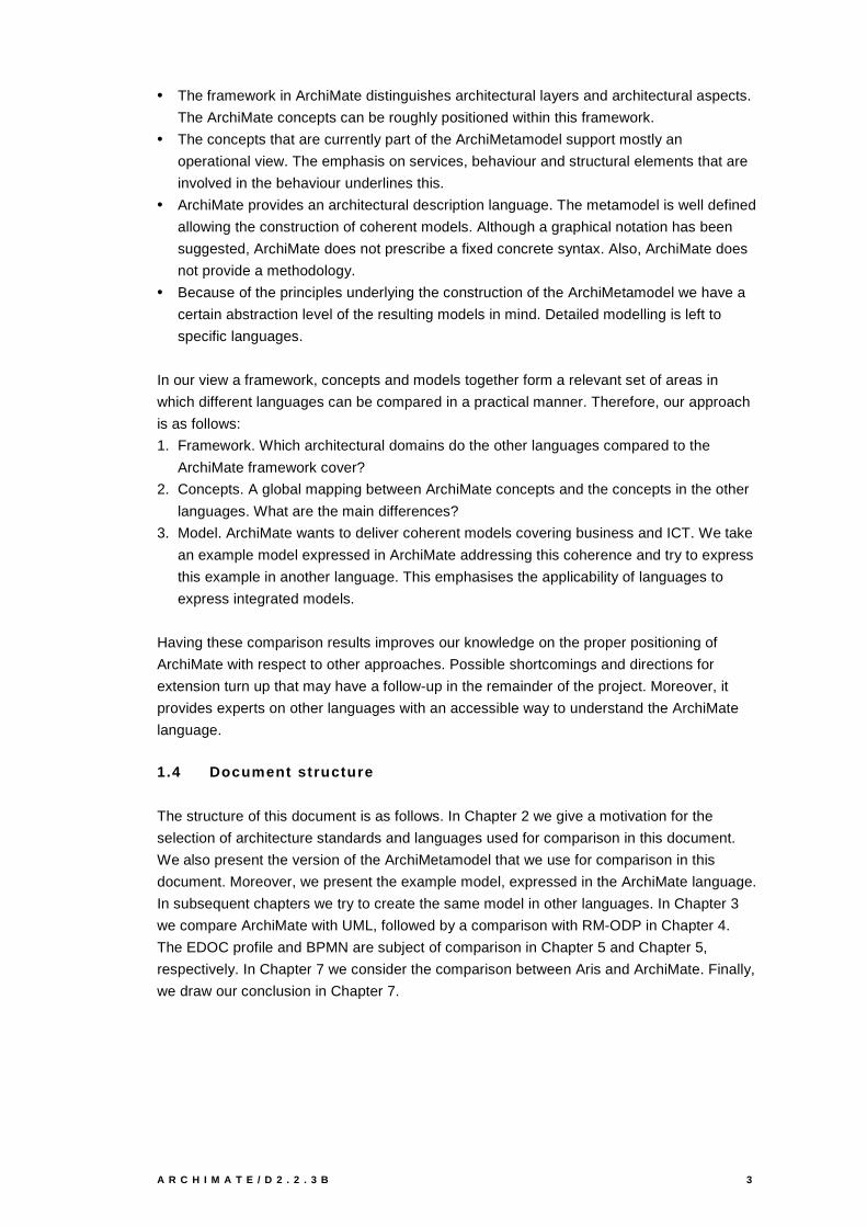
• The framework in ArchiMate distinguishes architectural layers and architectural aspects.
The ArchiMate concepts can be roughly positioned within this framework.
• The concepts that are currently part of the ArchiMetamodel support mostly an
operational view. The emphasis on services, behaviour and structural elements that are
involved in the behaviour underlines this.
• ArchiMate provides an architectural description language. The metamodel is well defined
allowing the construction of coherent models. Although a graphical notation has been
suggested, ArchiMate does not prescribe a fixed concrete syntax. Also, ArchiMate does
not provide a methodology.
• Because of the principles underlying the construction of the ArchiMetamodel we have a
certain abstraction level of the resulting models in mind. Detailed modelling is left to
specific languages.
In our view a framework, concepts and models together form a relevant set of areas in
which different languages can be compared in a practical manner. Therefore, our approach
is as follows:
1. Framework. Which architectural domains do the other languages compared to the
ArchiMate framework cover?
2. Concepts. A global mapping between ArchiMate concepts and the concepts in the other
languages. What are the main differences?
3. Model. ArchiMate wants to deliver coherent models covering business and ICT. We take
an example model expressed in ArchiMate addressing this coherence and try to express
this example in another language. This emphasises the applicability of languages to
express integrated models.
Having these comparison results improves our knowledge on the proper positioning of
ArchiMate with respect to other approaches. Possible shortcomings and directions for
extension turn up that may have a follow-up in the remainder of the project. Moreover, it
provides experts on other languages with an accessible way to understand the ArchiMate
language.
1.4 Do c u m en t s t r u c t u r e
The structure of this document is as follows. In Chapter 2 we give a motivation for the
selection of architecture standards and languages used for comparison in this document.
We also present the version of the ArchiMetamodel that we use for comparison in this
document. Moreover, we present the example model, expressed in the ArchiMate language.
In subsequent chapters we try to create the same model in other languages. In Chapter 3
we compare ArchiMate with UML, followed by a comparison with RM-ODP in Chapter 4.
The EDOC profile and BPMN are subject of comparison in Chapter 5 and Chapter 5,
respectively. In Chapter 7 we consider the comparison between Aris and ArchiMate. Finally,
we draw our conclusion in Chapter 7.

4 T E L E M A T I C A I N S T I T U U T
2 Standards and Languages
In this chapter we compare several architectural languages with the ArchiMate language.
We recognize that the list of comparable, complementing or competitive languages can
never be complete. We limit ourselves to a specific set of languages that in our view are
relevant from a standardisation or modelling perspective.
• RM-ODP (Reference Model for Open Distributed Processing). The RM-ODP is an ISO
and ITU standard. Both ISO and ITU are authoritative organisations. The RM-ODP
distinguishes several views on distributed systems and is the only standard that we know
of that explicitly discerns an enterprise viewpoint. Moreover, we have used RM-ODP as
a source of inspiration during the construction of the ArchiMetamodel.
• BPMN (Business Process Modelling Notation) is one of the standards developed by the
Business Process Management Initiative (BPMI.org). BPMN is becoming an international
standard for the notation of business process models. Business processes and
behaviour in general are an important part of the ArchiMetamodel. Members from the
ArchiMate Tool Vendor Forum have recognised the importance of the BPMN
development. Also, it attracts more and more scientific interest, considering the attention
it has received on recent scientific conferences. Within the TOGAF framework, BPMN is
proposed as the modelling language for business processes.
• UML. Involving UML in the comparison goes without saying. UML is the de facto
standard of software modelling in the world. Extension of UML’s usage to none-software
domains is rapidly growing. The new UML 2.0 provides important changes to facilitate
this extended usage. Not knowing how ArchiMate relates to UML is impossible.
• EDOC profile. Under guidance of the Object Management Group (OMG) a specification
for a UML Profile for Enterprise Distributed Object Computing (EDOC) was issued. The
UML Profile for EDOC is expected to become a key element of MDA, providing the
specification metamodel for enterprise systems. Having the OMG as origin and its
incorporation into MDA warrants a closer comparison.
• Aris: Aris is a product of a specific tool vendor. Aris has a great following and provides
possibilities for detailed process modelling. Moreover, the tool also supports UML
modelling. Given the large user base of Aris, it is relevant to see how it relates to
ArchiMate.
2.1 Th e Ar c h i Met am o d el
The ArchiMetamodel has developed in several phases. We have followed an inside-out
approach starting with the business layer and application layer, after which the metamodel
has been extended towards the technology layer and higher business layers (see D1.0,
Project Plan). On the other hand, practical cases provide input for the applicability of the
metamodel and guide its changes.
Although a larger part of the ArchiMetamodel is becoming stable, the metamodel is still
subject to changes while the project is running. The version that we have used is depicted in
the following figures. In D2.2.1 (Jonkers (ed.), 2003) and D2.2.2b (Van Buuren (ed.), 2003),
we elaborate on these metamodels. For clarity we present the layer-specific metamodels.

A R C H I M A T E / D 2 . 2 . 3 B 5
accessess
realises
accesses
assigned to
assigned to
realises
used by
usedby
assignedto
Businessrole
Businessbehaviour
Businesscollaboration
Meaning
Organisationalservice
Businessactor
aggregates
associatedwith
Businessevent
triggers
triggers
triggers
Repres-entation
Businessinteraction
triggers
triggersassigned
to
Businessobject
Product
used by
aggregates
composedof
aggregates
associatedwith
Businessinterface
Valuerealises
Contract
Figure 1: ArchiMate metamodel for the business layer
assigned to
accesses
realisesused by
assignedto
used by
assigned to
Applicationfunction
Applicationcollaboration
Applicationinterface
Applicationcomponent
Dataobject
Applicationservice
associatedwith
triggers
realises
used by
Applicationinteraction
composed of
aggregates
Figure 2: ArchiMate metamodel for the application layer
assignedto
used by
Communicationpath
Infrastructureinterface
Infrastructureservice
realises
Executionenvironment
Device Network
associatedwith
realises
NodeArtifact
assignedto
composedof
assignedto
associatedwith
Figure 3: ArchiMate metamodel for the technology layer

6 T E L E M A T I C A I N S T I T U U T
used byused by
Businessrole
Applicationcomponent
Applicationservice
Business layer
Application layer
Businessinteraction
Businessobject
Dataobject
realises
Application layer
Technology layerInfrastructure
interfaceInfrastructure
service
Artifact
Applicationcollaboration
Applicationinteraction
Businesscollaboration
Applicationinterface
used by
realises
realises realises
Applicationbehaviour
used byused by used by
Organisationalservice
Businessinterface
realises realises
Businessbehaviour
realises
realises
Product
aggregates
aggregates
aggregates
Node
Figure 4: ArchiMate relations between layers.
The layer-dependent metamodels are very useful when comparing languages that have
such layer-specific concepts themselves. Languages such as UML, on the other hand, offer
a set of more abstract concepts and diagrams. Therefore, we use the generic
ArchiMetamodel, which underlies the layer dependent models, for the comparison with UML
(see Figure 5).

A R C H I M A T E / D 2 . 2 . 3 B 7
accesses
assigned to
assigned to
*
*
assigned to
assignedto
*
*
realises
uses
realises *
*
*
uses
*
** *
2..**
*
**
*
*
*
Collaboration
Informativeelement
Meaning
Representation
Process/FunctionInteraction
Service
Actor
Role
Structuralelement
Interface
Value*
*Event
associatedwith
associated with
associated with
triggers
Object
triggers *
*
Behaviouralelement
accesses
*
composed ofaggregates
Figure 5: ArchiMate generic metamodel
2.2 Ex am p l e Ar c h i Mat e m o d el
Figure 6 illustrates a typical example of a model for which ArchiMate is intended. The model
covers several architectural layers and domains and shows the interrelationships between
them. The model describes claim processing between an Insurant and Insurer. During claim
processing, the Insurant makes use of several organisational services. An internal business
process that is assigned to the Insurer realises these services. Parts of the business
process are supported by applications and corresponding application services. During claim
processing, specific information is required that ‘flows’ through the process. Applications run
on specific hardware platforms.

8 T E L E M A T I C A I N S T I T U U T
Infrastructure
External infrastructure services
Application components and services
Roles and actors
External application services
External business services
Damage claiming process
Client Insurant InsurerArchiSurance
Registration PaymentValuationAcceptance
Customerinformation
service
Claimspaymentservice
Claimsadministration
service
Riskassessment
service
Paymentservice
Risk assessment
Claims administration
Financial application
Claiminformation
service
Claimregistration
service
Claimregistration
service
Customeradministration
service
Customer administration
Claimfiles
service
zSeries mainframe
DB2database
Riskassessment
EJB
Customerfiles
service
Sun Blade
iPlanetapp server
Claim
Claim data
Claim file
Figure 6: Example model, modelled by means of the ArchiMetamodel

A R C H I M A T E / D 2 . 2 . 3 B 9
3 UML
The Unified Modelling Language (UML) is usually defined as the standard object modelling
language. It is an open standard controlled by OMG, the Object Management Group. UML
is designed to model software systems, but several attempts have been made to use UML
for different domains, in particular to the business domain. These approaches are seriously
being hampered by the fact that UML does not offer semantics on the basis of which
consistency between diagrams from different languages can be checked.
UML is rather technical, whereas the world of business is semantically much richer and
therefore needs a different approach. This makes UML more difficult to understand for
people from domains other than the software/application domain. In addition, UML itself has
a strong inclination to express constructive details, whereas the business world would apply
a more declarative style in models leaving out unwanted details.
3.1 Fr am ew o r k o f UML v i ew p o i n t s
In this document we consider the latest version of UML, UML 2.0 (Object Management
Group, 2003a and 2003b). UML describes 13 sublanguages, each having own diagram to
model a specific aspect of a (software) system. These diagrams can be considered the
viewpoints of UML. The diagrams can be grouped in three categories of UML diagrams;
structure, behaviour and interaction.
The following diagrams model structure:
A Class diagram shows the structure of the system on the type level, using classes and
relationships between the classes. A class is a particular kind of thing logically important
enough to see instances of it frequently occurring in the various instantiated models. A
relationship expresses how classes correspond with each other, could depend on each
other, could influence each other, and could be connected to each other.
An Object diagram shows the structure of the system on the instance level at a certain point
in time, using objects and links between the objects. An object diagram is quite similar to a
class diagram. An object is a concrete thing of the type described by the class of which the
object is an instance of; a link between objects is the concrete relation of the type described
by the relationship of which the link is an instance. In this sense an object diagram
describes the concrete or instantiated logical structure of a system at a certain point in time,
exactly conforming to the type description of the corresponding class diagram.
A Package diagram shows how model elements are grouped into packages as well as the
dependencies between packages. A package can import individual elements or other
packages.
A Composite structure diagram depicts physical connections between (logical) elements (like
classes/objects, packages, use cases). With the diagram, a class can be hierarchically
decomposed into an internal structure that represents the runtime decomposition of the
1 0 T E L E M A T I C A I N S T I T U U T
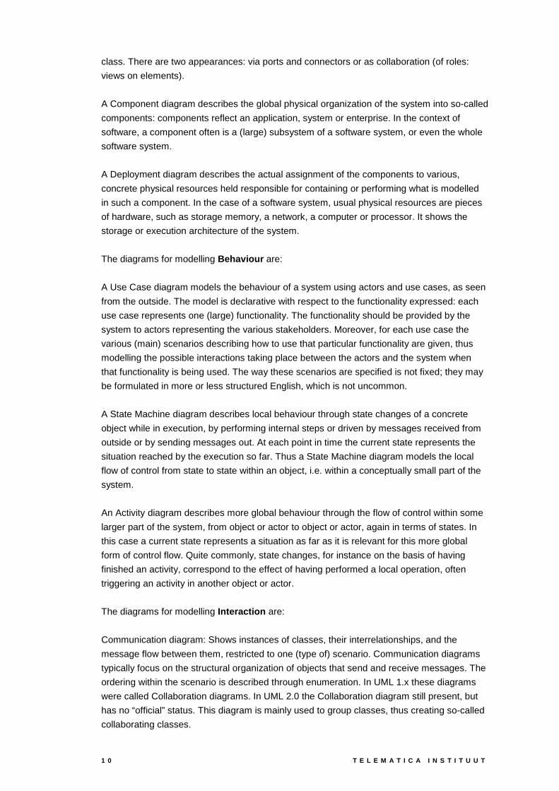
class. There are two appearances: via ports and connectors or as collaboration (of roles:
views on elements).
A Component diagram describes the global physical organization of the system into so-called
components: components reflect an application, system or enterprise. In the context of
software, a component often is a (large) subsystem of a software system, or even the whole
software system.
A Deployment diagram describes the actual assignment of the components to various,
concrete physical resources held responsible for containing or performing what is modelled
in such a component. In the case of a software system, usual physical resources are pieces
of hardware, such as storage memory, a network, a computer or processor. It shows the
storage or execution architecture of the system.
The diagrams for modelling Behaviour are:
A Use Case diagram models the behaviour of a system using actors and use cases, as seen
from the outside. The model is declarative with respect to the functionality expressed: each
use case represents one (large) functionality. The functionality should be provided by the
system to actors representing the various stakeholders. Moreover, for each use case the
various (main) scenarios describing how to use that particular functionality are given, thus
modelling the possible interactions taking place between the actors and the system when
that functionality is being used. The way these scenarios are specified is not fixed; they may
be formulated in more or less structured English, which is not uncommon.
A State Machine diagram describes local behaviour through state changes of a concrete
object while in execution, by performing internal steps or driven by messages received from
outside or by sending messages out. At each point in time the current state represents the
situation reached by the execution so far. Thus a State Machine diagram models the local
flow of control from state to state within an object, i.e. within a conceptually small part of the
system.
An Activity diagram describes more global behaviour through the flow of control within some
larger part of the system, from object or actor to object or actor, again in terms of states. In
this case a current state represents a situation as far as it is relevant for this more global
form of control flow. Quite commonly, state changes, for instance on the basis of having
finished an activity, correspond to the effect of having performed a local operation, often
triggering an activity in another object or actor.
The diagrams for modelling Interaction are:
Communication diagram: Shows instances of classes, their interrelationships, and the
message flow between them, restricted to one (type of) scenario. Communication diagrams
typically focus on the structural organization of objects that send and receive messages. The
ordering within the scenario is described through enumeration. In UML 1.x these diagrams
were called Collaboration diagrams. In UML 2.0 the Collaboration diagram still present, but
has no “official” status. This diagram is mainly used to group classes, thus creating so-called
collaborating classes.

A R C H I M A T E / D 2 . 2 . 3 B 1 1
A Sequence diagram shows instances of classes and the message flow between them. In
contrast to a communication diagram a message flow is not restricted to one (type of)
scenario, but to as many scenarios as wanted. The ordering within the scenarios is not
through enumeration but along a scale-less time axis, so-called lifelines. Along a vertical time
axis - the lower the later - the order of sending and receiving messages (events, triggers,
data, and signals) between objects (and actors) is indicated.
An Interaction Overview diagram combines the flow structure of activity diagrams with
sequence diagrams. It does so by replacing activities by sequence diagrams; their lifelines,
so to speak, correspond to the swim lanes. So all "activities" are formulated in terms of
interaction scenarios. By reusing the flow structure of activity diagrams, interaction overview
diagrams are "complex" sequence diagrams with many smaller sequence diagram-like
fragments.
A Timing diagram combines a sequence diagram and explicit time; instead of lifelines,
sequences of (local) state changes specify the scenarios where time annotations make time
explicit. It is typically used to show the subsequent state changes of one or more objects
over time in response to events, internal as well as external.
Summarizing the above, UML offers a set of 13 diagrams for modelling different aspects of
software systems. But these diagrams may be used for modelling more general dynamic
systems as well.
Figure 7. Coverage of UML viewpoints
There is no grouping of UML diagrams into business, application and technical/infrastructure
present, since UML was only intended for software systems. Therefore it is difficult to make a
distinction between business, application and technical. Therefore, the lines that create this
division are dashed, to note that this is not a strict division.
Although it is not a priori clear how to apply the UML concepts to modelling business
architecture, we have projected the different diagram types into the ArchiMate framework.

1 2 T E L E M A T I C A I N S T I T U U T
3.2 Tr an s l at i o n o f A r c h i Mat e c o n c ep t s t o UML
We start with analysing the structural concepts, followed by the behavioural concepts and
ending with the informative concepts. The structural concepts are the concepts that are
easiest to understand since they are similar to well known structural notions in other
formalisms. So they are relatively easy to translate. The behavioural concepts are a bit less
common. Finally, the informative concepts are even more difficult to understand and
therefore to translate, as they are rather uncommon.
For the translation we have used the generic ArchiMetamodel. We translate from ArchiMate
to UML. The ArchiMate concept is highlighted in bold; the UML concept is on the right side
of the arrow.
Our approach in translating ArchiMate metamodel concepts to UML is to match properties
based on the characterizations of ArchiMate concepts. In some cases a match can be found
for properties corresponding to different UML concepts.
The translation shows the ArchiMate concept, followed by the chosen UML concept(s). In our
approach the arguments for our choices of UML concepts are given after the translation:
Structural Element � Class. The class always is an abstract class, as it will have no
instances. It contains the common (structural) attributes for every structural element
Object � Class. Behaviour is of no real interest. So the class only has the CRUD operations
(Create, Read, Update, and Delete) to perform basic operations. Furthermore, it can have all
kinds of attributes.
Actor � Class. An actor is something (person, department, active piece of software) that
fulfils Roles. Only the structure of such an Actor is described in a class. The operations
corresponding to its specific Role(s) do not belong to it. Instead it has special associations
with these Roles (in their translated form) together with special operations playRole(..) via
which it can start acting according to a certain role. In principle an actor could also be
mapped to an UML object, which is a class instance. With respect to a class, an object is
more detailed and as such adds information. Since, we consider high-level structure in
ArchiMate we prefer to map an actor to a class instead of an object.
Role � Class. A Role can be fulfilled by an Actor. It gives the Actor its behaviour. To that
aim it offers its operations (Services) to elsewhere via its Interface. Such a Role is part of
Collaboration. As soon as an instance of Collaboration exists, the Roles belonging to the
Collaboration are started by calling the playRole(..) operation of the Actors playing those
Roles.
Collaboration � Class and Composite Structure, in particular in its visual form (UML)
collaboration. The roles occurring in the UML collaboration are indeed the above UML
classes for the Roles. The links between the roles in the UML collaboration are not
(immediately) there. The collaboration can be drawn when using Collaboration and Role
together.

A R C H I M A T E / D 2 . 2 . 3 B 1 3
Interface � (UML) Interface, as occurring in class diagrams and composite structure
diagrams. It effectively separates provided and required functionality from implementation.
Behavioural Element � Interaction; Sequence or Activity. This covers the translation of
both Interaction and Process/Function. So we refer to the discussion of the translation of
these two concepts.
Interaction � Sequence or Interaction Overview. Lifelines correspond to the Roles
participating in the Collaboration the Interaction is assigned to. As long as the details of the
messages exchanged are unknown, such a sequence diagram has to remain incomplete, as
the translation into UML should not reflect details not occurring in the original ArchiMate
model. When there is a nested hierarchy of ArchiMate Interactions, an Interaction Overview
Diagram can easily reflect a similar hierarchical structure.
Process/Function � Activity or Sequence. Depending on the relevance of the internal
behaviour versus the communicative behaviour related to a Role, one could prefer a model
reflecting the (internal) activities of a Role, or a model reflecting the interaction with a Role. If
the Process/Function is assigned to a Role which itself is a Collaboration, the activities taking
place can themselves be organized according to swim lanes. Such swim lanes then
correspond to the (smaller, nested) Roles within that Collaboration.
Event � Interaction in Sequence or Activity or Interaction Overview: a concrete exchange of
a message, a trigger, a signal, a (UML) event, often between two lifelines. Usually it either
triggers a whole sequence of such interactions or it closes such a sequence.
Service � Interface Operation. A Service reflects functionality that is provided or required.
The clear separation from any implementation of such a Service remains valid in the
translation, as UML interfaces indeed hide such solutions.
Informative Element � Note or Use Case. This covers the translation of both Value and
Meaning. So we refer to the discussion of the translation of these two concepts.
Value � The ArchiMate concept value appears to have no direct counterpart in UML.
However, some UML concept may be useful to express the ArchiMate value concept. A Use
Case(s) expresses intended usage of the model towards the environment of the model by
informing about the model's functionality. The phrasing of this usage is not so much in terms
of the (internal) design solution of the model but in terms of what is relevant for the model's
environment, e.g. business goals or business strategy. In case an ArchiMate value has a
more text like nature, a UML note might be a good means to represent the value concept.
Meaning � Note(s). They express an explanation of structural parts of the model in terms of
what is relevant for the model's environment.
Representation � Note(s) or Class. Like the notes corresponding to Meaning, they also
express an explanation of structural parts of the model in terms of what is relevant for the
environment. But here it is more like a(n extended) view on the underlying structural parts.
So the formulation of the explanation, although in terms of what is relevant for the
environment, is structurally related to the (data or business) object they are associated with.

1 4 T E L E M A T I C A I N S T I T U U T
If the similarity in structure between the underlying (data or business) Object is strong
enough, the UML translation of representation can make this more explicit by means of a
class instead of one or more notes.
Summarising our translation, we present the following table.
ArchiMate concept UML equivalent concept
Structural Element Class
Object Class
Actor Class
Role Class
Collaboration Collaboration or Class
Interface Interface
Behavioural Element Sequence or Activity
Interaction Sequence or Interaction Overview
Process/Function Activity or Sequence
Event Interaction in Sequence
Service Operation of an Interface
Informative Element Use Case(s) or Note(s)
Purpose Use Case(s)
Meaning Note(s)
Representation Note(s) or Class
Table 1: Translation from ArchiMate to UML concepts
The relations from the ArchiMate metamodel are very important too, as they express how in
any concrete ArchiMate model the concrete instances of the different metamodel concepts
can be related.
So, by translating the ArchiMate metamodel relations in a straightforward manner to UML
relationships (associations, specialisations, and aggregations) one can infer the required
ArchiMate consistencies into the corresponding UML model. This is really relevant for a
possible UML profile for the ArchiMate approach. Consistency checking and management
between different kinds of UML diagrams can be based on the consistency of the
ArchiMetamodel.
3.3 Ex am p l e m o d el ex p r es s ed i n UML
The example provided is expressed in UML in two different approaches. The first approach
is to express the example in one UML diagram. The second approach is to use ArchiMate
as an “umbrella” language, making it possible to express the example in more than one

A R C H I M A T E / D 2 . 2 . 3 B 1 5
UML view. Separate UML views are ‘glued’ together with ArchiMate. In particular, some
consistency between separate UML views/diagrams can be checked.
Modeling the complete example in one view (diagram) can be difficult, since there is not one
view that covers all domains and represents these domains correctly. The Class Diagram is
the closest to this view.
Figure 8: Example model, modelled with UML classes
It can be difficult to model domains outside the structural domain, since the Class diagram is
not designed to model concepts from the behavioral or informational domains. It is possible,
but not easy and the result can be very difficult to use. Mapping the example model
provided to UML results in the following Class Diagram.
The Insurer Role has the four processes as operations. The services that these processes
provide are the communication ‘points’ between the insurer and insurant role and are
explicitly specified in the interface ‘Damage Claiming Process’.
The process Valuation is private because it does not offer any service. The other processes
are public since they offer services to the Insurant. The order of occurrence of the
1 6 T E L E M A T I C A I N S T I T U U T
processes is lost in this translation. These details cannot be preserved in a Class diagram in
an appropriate way, only by using notes.
The four components have their interfaces with the services they offer. The dependencies
between the Role Insurer and the components and the dependencies between the
components and the infrastructure are presented as dependencies.
Between the two artifacts and the component and role are two dependencies. The
dependency between the artifact and the role is from the artifact to the role because the
process(es) in the role fills the artifact. The dependency between the artifact and component
is from the component to the artifact because the component uses information from the
artifact.
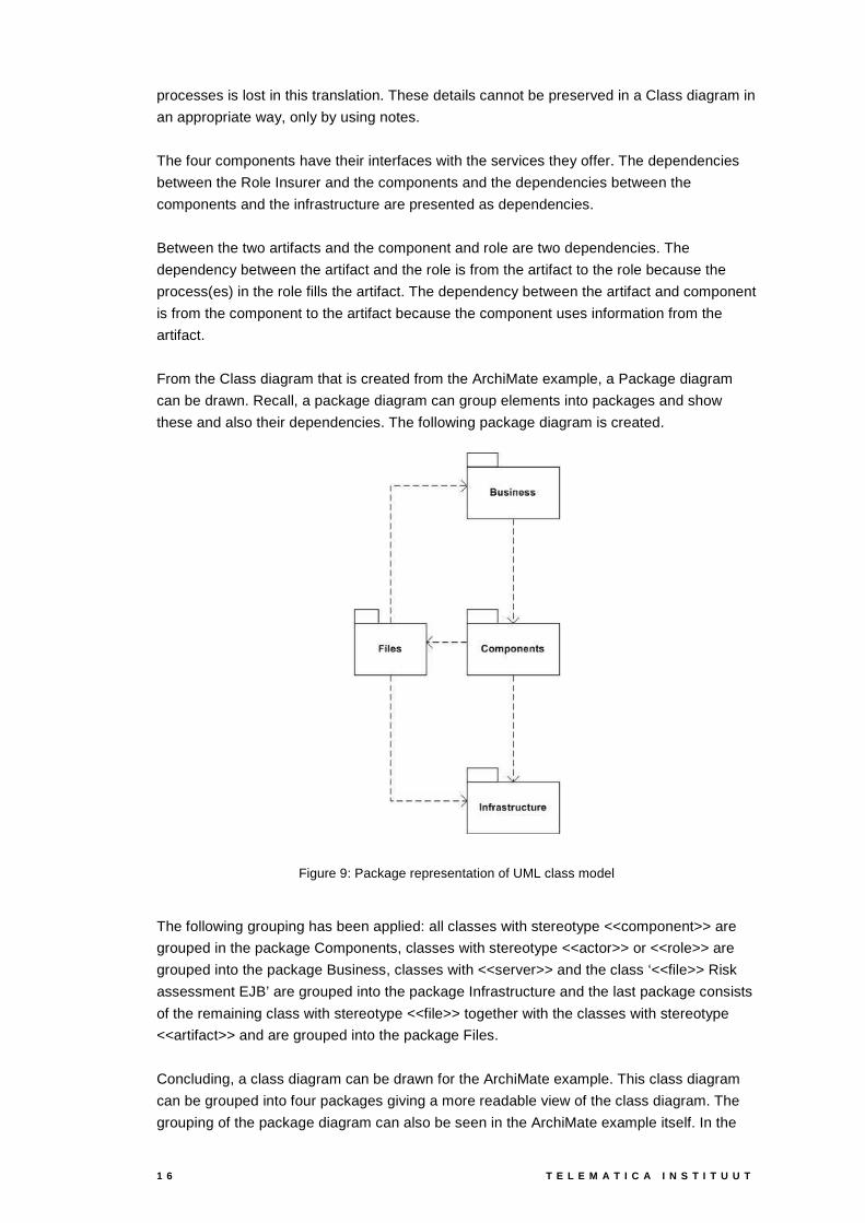
From the Class diagram that is created from the ArchiMate example, a Package diagram
can be drawn. Recall, a package diagram can group elements into packages and show
these and also their dependencies. The following package diagram is created.
Figure 9: Package representation of UML class model
The following grouping has been applied: all classes with stereotype <<component>> are
grouped in the package Components, classes with stereotype <<actor>> or <<role>> are
grouped into the package Business, classes with <<server>> and the class ‘<<file>> Risk
assessment EJB’ are grouped into the package Infrastructure and the last package consists
of the remaining class with stereotype <<file>> together with the classes with stereotype
<<artifact>> and are grouped into the package Files.
Concluding, a class diagram can be drawn for the ArchiMate example. This class diagram
can be grouped into four packages giving a more readable view of the class diagram. The
grouping of the package diagram can also be seen in the ArchiMate example itself. In the

A R C H I M A T E / D 2 . 2 . 3 B 1 7
example four groups are present. These groups are equal to the packages in the package
diagram.

1 8 T E L E M A T I C A I N S T I T U U T
ArchiMate as “ umbrella” language
The second approach is using ArchiMate as umbrella language, gluing separate diagrams
together. There is no direct coupling between the diagrams through their own language, in
this case UML.
I n fra s tr u c tu re
E x te rn a l in fr a s tr u c tu re s e rv ic e s
A p p l ic a tio n c o m p o n e n ts a n d s e rv ic e s
R o le s a n d a c to r s
E x te rn a l a p p lic a t io n s e r v ic e s
E x te rn a l b u s in e s s s e r v ic e s
D a m a g e c la im in g p ro c e s s
C lie n t In s u ra n t In s u re rA rc h iS u r a n c e
R e g is t ra tio n P a y m e n tV a lu a t io nA c c e p ta n c e
C u s to m e rin fo r m a t io n
s e rv ic e
C la im sp a y m e n ts e r v ic e
C la im sa d m in is t ra tio n
s e rv ic e
R is ka s s e s s m e n t
s e rv ic e
P a y m e n ts e rv ic e
R is k a s s e s s m e n t
C la im s a d m in is tra t io n
F in a n c ia l a p p lic a tio n
C la imin fo r m a tio n
s e rv ic e
C la imr e g is t ra tio n
s e rv ic e
C la imr e g is t ra tio n
s e rv ic e
C u s to m e ra d m in is tra t io n
s e rv ic e
C u s to m e r a d m in is t ra tio n
C la imf ile s
s e r v ic e
z S e r ie s m a in f ra m e
D B 2d a ta b a s e
R is ka s s e s s m e n t
E J B
C u s to m e rfi le s
s e r v ic e
S u n B la d e
iP la n e ta p p s e rv e r
C la im
C la im d a ta
C la im f i le
Figure 10: Example model, ArchiMate as an umbrella language
The example can be modeled using three different diagram types: class, component and
deployment diagrams. Which parts of the example are modeled by which diagram is shown
by the different squares, having different line types for the different diagrams. The results of
this approach are displayed on the next page.
The difference between these two approaches is, although both approaches contain the
same information and both approaches are represented the same package diagram, the
difference in visual notation. The second approach (“umbrella” approach) allows a user to
use a richer set of UML diagrams and thereby express properties in a visual manner. These
properties can also be expressed in a class diagram (using stereotypes), but when
modeling large models it will get difficult to read and understand.
In addition, the stereotypes used in a class diagram can be less intuitive then visual
representations of the same properties (for example a stereotype indication for a component
or a visual symbol for component).
Deployment
Diagram
Component
Diagram
Class
Diagram

A R C H I M A T E / D 2 . 2 . 3 B 1 9
When applying the umbrella approach to the example, the following diagrams are produced.
Figure 11: Example model, UML diagrams connected by ArchiMate as an umbrella language
I n fr a s tr u c t u r e
E x t e r n a l in f r a s t r u c tu r e s e r v ic e s
A p p l ic a t io n c o m p o n e n ts a n d s e r v ic e s
R o le s a n d a c t o r s
E x t e r n a l a p p l ic a t io n s e r v ic e s
E x t e r n a l b u s in e s s s e r v ic e s
D a m a g e c la im in g p r o c e s s
C lie n t In s u r a n t In s u r e rA r c h iS u r a n c e
R e g is t r a t io n P a y m e n tV a lu a tio nA c c e p ta n c e
C u s to m e rin f o r m a t io n
s e r v ic e
C la im sp a y m e n ts e r v ic e
C la im sa d m in is t r a t io n
s e r v ic e
R is ka s s e s s m e n t
s e r v ic e
P a y m e n ts e r v ic e
R is k a s s e s s m e n t
C la im s a d m in is t r a t io n
F in a n c ia l a p p l ic a t io n
C la imin fo r m a tio n
s e r v ic e
C la imr e g is t r a t io n
s e r v ic e
C la imr e g is t r a t io n
s e r v ic e
C u s to m e ra d m in is t r a t io n
s e r v ic e
C u s to m e r a d m in is t r a t io n
C la imfi le s
s e r v ic e
z S e r ie s m a in fr a m e
D B 2d a t a b a s e
R is ka s s e s s m e n t
E J B
C u s t o m e rf i le s
s e r v ic e
S u n B la d e
iP la n e ta p p s e r v e r
C la im
C la im d a t a
C la im f i le

2 0 T E L E M A T I C A I N S T I T U U T
3.4 Co n c l u s i o n
The purpose of this comparison is to select suitable UML notions or UML diagrams that can
serve as translations of the various ArchiMate concepts. We have succeeded in translating
the ArchiMate concepts into UML, and shown two approaches of translating ArchiMate
models to UML models.
When using UML directly, there is a very strong inclination to express technical details.
Although such details certainly make sense, from the perspective of a software developer,
these details are not present in the original ArchiMate example model. This results in
leaving out (unwanted) details, making it difficult to use and explain UML. In particular since,
when using the declarative style, sometimes the resulting UML diagrams are strictly
speaking incomplete. As a result this makes it difficult to verify the correctness of a diagram.
The ArchiMate approach hides technical details. ArchiMate models tend to leave out
technical details concerning communication and other behavioural aspects. In this way it is
left open which participant (role) in an interaction exactly does what for whom and when.
Perhaps it is UML's property of nearly forcing a UML modeller to add such technical,
constructive details, why some authors argue that UML is not sufficiently suited for the
modelling needs of business architects, and the like.
ArchiMate and UML can be combined. Alignment and integration between different UML
diagrams can be verified through ArchiMate. On the other hand ArchiMate models may be
studied, via its UML translation, in the context of UML models.
A R C H I M A T E / D 2 . 2 . 3 B 2 1
4 RM-ODP
The Reference Model for Open Distributed Processing (RM-ODP) is usually defined as a
framework of abstractions, i.e. a set of modelling concepts relevant for the specification of
ODP systems and an architecture providing a structure for these concepts. RM-ODP’s
objective is to define modelling concepts for potentially distributed systems that are totally
independent of any existing analysis / design method, notation or programming language.
The modelling concepts are supposed to be abstract enough and precisely enough defined
to enable a mapping on to any methods or languages. RM-ODP is essentially based on the
definition of a number of viewpoints providing five different perspectives on the ODP
system. These five viewpoints are:
• the enterprise viewpoint, which is concerned with the business activities of the specified
system;
• the information viewpoint, which is concerned with the information that needs to be
stored and processed in the system;
• the computational viewpoint, which is concerned with the description of the system as a
set of objects that interact at interfaces - enabling system distribution;
• the engineering viewpoint, which is concerned with the mechanisms supporting system
distribution;
• the technology viewpoint, which is concerned with the detail of the components from
which the distributed system is constructed.
Because of the enterprise architecture context of ArchiMate, we compare in this section the
RM-ODP enterprise viewpoint with ArchiMate. It is possible that more RM-ODP viewpoints
are required to create enterprise architectures in the sense of ArchiMate. However, in this
document we restrict ourselves to the enterprise viewpoint. The enterprise viewpoint in RM-
ODP describes a “system” with regard to its functionality, how it takes places in its
environment, how it interacts with it and the corresponding business requirements,
management/usage rules that govern its design. Typically, the enterprise viewpoint has the
decision makers as main stakeholders in mind. Note that this already appears to be a first
difference with ArchiMate, since ArchiMate aims to yield an integrated architecture of an
enterprise suitable for different stakeholders.
4.1 Fr am ew o r k RM-ODP en t er p r i s e v i ew p o i n t
The RM-ODP enterprise viewpoint language comprises concepts, structures and rules for
developing, representing, and reasoning about a specification of an ODP system from the
enterprise viewpoint. Also, it provides rules that establish correspondences between the
enterprise viewpoint and the other viewpoint languages for the overall consistency of a
specification (ITU-T X911). Similar to the ArchiMate concepts, the concepts defined in the
RM-ODP enterprise viewpoint cover informational, structural and behavioural aspects.
In Figure 12 we project the RM-ODP enterprise viewpoint on the ArchiMate framework. For
completeness we have also projected the remaining four viewpoints into the framework.

2 2 T E L E M A T I C A I N S T I T U U T
Businesslayer
Applicationlayer
Technicalinfrastructurelayer
Informationaspect
Behaviouraspect
Structureaspect
Enterprise viewpoint
Computational viewpoint
Engineering viewpoint
Technology viewpointInform
ationview
point
Figure 12. Coverage of RM-ODP enterprise viewpoint
The RM-ODP enterprise viewpoint is placed in the business layer of the ArchiMate
framework (see above figure). At a very abstract level, concepts from the application layer
and technical layer can be expressed with the RM-ODP enterprise language. However,
more detailed concepts for these layers are addressed in other corresponding viewpoints
languages. These concepts are linked to the enterprise language by means of so-called
correspondence rules to ensure consistency between the different viewpoint languages.
In contrast to the current version of the ArchiMetamodel, RM-ODP explicitly addresses
contracts, policies and accountability concepts. These concepts may be taken into account
in the extension of the ArchiMetamodel with higher-level business concepts (D2.2XXX).
Additionally, the other viewpoints of RM-ODP are positioned within the framework. Less
research has been performed for this positioning. They present a rough interpretation of
these viewpoints.
4.2 Co n c ep t s /m et am o d el
In recommendation ITU-T X911 the RM-ODP five categories for concepts are defined:
• System concepts
• Community concepts
• Behaviour concepts
• Policy concepts
• Accountability concepts
The system concepts cover the scope and application field of the ODP-system, the policy
concepts define a set of rules with respect to a particular Value, and the accountability
concepts addresses the obligation of specific parties within an organization. The
ArchiMetamodel currently covers none of these concepts. For the community and behaviour
concepts related concepts occur in the ArchiMetamodel. These concepts are regarded in
the current comparison.

A R C H I M A T E / D 2 . 2 . 3 B 2 3
Community
Role
InterfaceRole
Objective
EnterpriseObject
Communityobject
Behaviour
Resource Artefact Actor
StepProcess Step
Action
assigned
assigned
leads to
has
fulfils
associated
referenced in
essential to
Figure 13: "Informal” reconstruction of enterprise viewpoint metamodel from RM-ODP ITU-T X.911 Standard
Figure 6 shows our reconstruction of a metamodel for the enterprise viewpoint of RM-ODP
corresponding to the community and behaviour concepts mentioned above. Although it
appears that the relations between concepts are quite well defined, we remark that these
relations are not defined unambiguously and are mostly derived from textual descriptions of
concepts and their usage. However, the comparison with ArchiMate concepts is facilitated if
not only strict semantics of concepts are compared, but also relations with other concepts
are taken into account. In our opinion, too much room is left for different interpretations.
In RM-ODP an objective is defined as: “Practical advantage of intended effect, expressed
as preferences about future states.” The objective is expressed as a contract, which
specifies how the objective can be met. In ArchiMate the value concept appears to be its
counterpart. A Value expresses the intended functionally of a service to an external user.
Within RM-ODP the objective is linked to a community, which is a structural concept. In
ArchiMate the service concept connects the Value with corresponding structural concepts
such as business interfaces and business roles. The service concept is not explicitly
supported in RM-ODP.

2 4 T E L E M A T I C A I N S T I T U U T
An enterprise object is any object in an enterprise specification, which is felt to be
necessary or desirable to specify the system from the enterprise viewpoint or to understand
the enterprise specification. Resource, artefact and actor are specialisations of an
enterprise object. An actor participates in an action, an artefact is referenced in an action,
and a resource is essential to some behaviour and may require allocation or may become
unavailable. Equivalent concepts in ArchiMate can be found in the structural aspect namely:
business roles, business actor, application component, business object, data object,
business interfaces and application interfaces. All these ArchiMate concepts are directly
related to behavioural concepts and describe specific assignable parts of an enterprise
system. In general the resource enterprise object does not occur in ArchiMate. Only in case
a resource represents a structural element from the application or technical layer there is an
ArchiMate counterpart.
A community object is a composite enterprise object that represents a community.
Although collaboration in ArchiMate aggregates business roles and not business actor
(enterprise object in RM-ODP) the business collaboration concept resembles the
community object. However, passive enterprise objects such as resources and artefacts,
represented by business object, do not form part of the collaboration in ArchiMate.
A community appears to be a central concept in RM-ODP. However, we could not find an
explicit definition in ITU-T X.902. A community is described as a configuration of enterprise
objects formed to meet an objective. Behaviour associated with a community is such that it
meets its objective. The collective behaviour of the community is specified in a collection of
roles, assignment of roles to behaviour and policies and accountabilities that apply to the
roles and behaviour. In ArchiMate there is no direct counterpart. However, the community
concept resembles the business domain concept as it is used by, among others, ABN
AMRO. In their view, a business domain describes an “organisational entity” with dedicated
objectives and responsibilities. A business domain has its own organisational and
application infrastructure to realise its objectives.
In our opinion, the use of the community and community object in RM-ODP are not clearly
separated.
A role is an identifier for behaviour, which may appear as a parameter in a template for a
composite object, and which is associated with one of the component objects of the
composite object. In ArchiMate the business role and application component are its
counterpart. Both these concepts are identifiable concepts that are assigned to specific
behaviour.
An interface role is a role of a community identifying behaviour, which takes place with the
participating objects that are not a member of that community. The counterpart in ArchiMate
is the business interface that declares how a business role can connect with its
environment.
A process in RM-ODP is defined as a collection of steps taking place in a prescribed
manner and leading to an objective. A process aggregates more detailed behavioural
concepts such as actions and steps. This concept corresponds well with ArchiMate’s
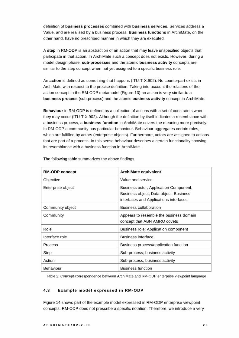
A R C H I M A T E / D 2 . 2 . 3 B 2 5
definition of business processes combined with business services. Services address a
Value, and are realised by a business process. Business functions in ArchiMate, on the
other hand, have no prescribed manner in which they are executed.
A step in RM-ODP is an abstraction of an action that may leave unspecified objects that
participate in that action. In ArchiMate such a concept does not exists. However, during a
model design phase, sub-processes and the atomic business activity concepts are
similar to the step concept when not yet assigned to a specific business role.
An action is defined as something that happens (ITU-T-X.902). No counterpart exists in
ArchiMate with respect to the precise definition. Taking into account the relations of the
action concept in the RM-ODP metamodel (Figure 13) an action is very similar to a
business process (sub-process) and the atomic business activity concept in ArchiMate.
Behaviour in RM-ODP is defined as a collection of actions with a set of constraints when
they may occur (ITU-T X.902). Although the definition by itself indicates a resemblance with
a business process, a business function in ArchiMate covers the meaning more precisely.
In RM-ODP a community has particular behaviour. Behaviour aggregates certain roles,
which are fulfilled by actors (enterprise objects). Furthermore, actors are assigned to actions
that are part of a process. In this sense behaviour describes a certain functionality showing
its resemblance with a business function in ArchiMate.
The following table summarizes the above findings.
RM-ODP concept ArchiMate equivalent
Objective Value and service
Enterprise object Business actor, Application Component,
Business object, Data object; Business
interfaces and Applications interfaces
Community object Business collaboration
Community Appears to resemble the business domain
concept that ABN AMRO covets
Role Business role; Application component
Interface role Business interface
Process Business process/application function
Step Sub-process; business activity
Action Sub-process, business activity
Behaviour Business function
Table 2: Concept correspondence between ArchiMate and RM-ODP enterprise viewpoint language
4.3 Ex am p l e m o d el ex p r es s ed i n RM-ODP
Figure 14 shows part of the example model expressed in RM-ODP enterprise viewpoint
concepts. RM-ODP does not prescribe a specific notation. Therefore, we introduce a very

2 6 T E L E M A T I C A I N S T I T U U T
basic visual notation. The concept type is written, as a kind of UML stereotype, between
triangular brackets, and the name of the instance is written underneath. Given the scope of
the RM-ODP enterprise viewpoint, only the business layer can be modelled in detail.
However, certain parts of the application layer and technology layer can be modelled by
means of the high-level enterprise objects.
Conform to the RM-ODP approach we define a community: the insurance community.
Corresponding enterprise objects represents business actors, Business Roles, Information
objects, Application components and nodes from the ArchiMate language. The insurance
community consists of these enterprise objects. Also, the damage claiming process is
modelled by means of actions, which are causally related (ITU-T X.902)
The various enterprise objects are linked through the damage claiming process. Depending
on their role in the process the enterprise objects are actors, resources or artefacts.
Although the relations are not defined explicitly (or clearly) in the ITU standard, we have
used three different relation types corresponding to the different enterprise objects shown in
Figure 13.
Insurance community
Insurancecommunity
Insurance Community
<< Process >> Damage claiming process
<<EO,Actor>>Client
<<Role>>Insurant
<<EO,Actor>>ArchiSurance
<<Role>>Insurer
fullfills fulfills
<<Action>>Registration
<<Action>>Acceptance
<<Action>>Valuation
<<Action>>Payment
Causility Causility Causility<<EO,Artefact >>Claim
<<EO, Artefact >>Claim Data
<<EO, Artefact >>Claim file
<<EO, resource>>Claims
administration
<<EO, resource>>Customer
administration
<<EO, resource>>Risk assessment
<<EO, resource>>application
Assigned
essential to
essential to
essential to
essential to
Insurance community<<EO, resource>>Zseries mainframe
<<EO, resource>>Sun blade
<<EO, artefact>>Risk assessment
EJB
Referen-cedin
essential to
essential to
essential to
refe
renc
ed in
refe
renc
ed in
<<Role>>Customer
administrator
<<Role>> <<Role>> <<Role>>
<<Role>> <<Role>> <<Role>>
Figure 14: Example model, modelled with RM-ODP enterprise viewpoint concepts

A R C H I M A T E / D 2 . 2 . 3 B 2 7
In comparison to the ArchiMate example model we conclude that:
• RM-ODP does not support the service concept. However, RM-ODP rules state that at
least one role has to be coupled to an enterprise object. These roles resemble the
external services in some sense.
• Relationships in RM-ODP are not defined explicitly (or clearly)
• In the enterprise language the community concepts plays a central role. Through the
process (behaviour) the various enterprise objects are linked. No direct relationships
between objects are defined.
• More detailed concepts of the information, application and technology domain in RM-
ODP are defined in the informational, computational and technological viewpoint
languages. Correspondences are defined in the standard for linking the different
viewpoints
4.4 Co n c l u s i o n
From the comparison of RM-ODP with ArchiMate, some general observations can be made
and conclusions can be drawn.
• RM-ODP is an international standard. The five viewpoints cover an ODP system quite
well. The enterprise viewpoint addresses structural, behavioural as well as contractual
and accountability aspects. Especially the latter two provide valuable input for extension
of the ArchiMetamodel.
• RM-ODP’s objective is to define architecture concepts that are supposed to be
sufficiently abstract and precisely enough defined to enable a possible mapping onto any
method or language. Also, no methodology or syntax is prescribed. RM-ODP, as its
name clearly suggests, is more of a reference model than a modelling language. In our
view, this follows from the loosely defined relations between concepts. Relations are not
made explicit. This makes it difficult to construct models in an unambiguous way.
• The RM-ODP standards are difficult to access. More recent standards rely heavily on
earlier standards. Also, the intended generality of RM-ODP hinders accessibility.
Studying an RM-ODP standard in detail is time consuming. It presents a good insight
into, and an overview of relevant architectural concepts and ideas. However, the reader
is left without an instrument to materialise his knowledge.
• It is very hard to find example models expressed in RM-ODP enterprise viewpoint
language. The resulting models are expressed at a very high level of abstraction.
• In order to achieve coherent models, covering different architectural layers, more RM-
ODP viewpoint language have to be considered. The enterprise viewpoint by itself is not
enough. To this purpose correspondences with other viewpoints are defined.

2 8 T E L E M A T I C A I N S T I T U U T
5 EDOC profile for UML
EDOC - Enterprise Distributed Object Computing - is a UML profile. The specification of this
so-called EDOC profile is a product of the Object Management Group (OMG) (Object
Management Group, 2002). The aim of the profile is to provide a modelling framework
enabling substantial simplification in developing components for enterprise computing
systems in line with business functions and business processes. To that aim, the modelling
framework provides a platform independent, collaboration-based approach. The approach
can be used for business modelling and for (computing) systems modelling separately but
also for modelling integration of business processes and applications. Moreover, the
approach can be applied on different granularity levels and with different degrees of
coupling, while remaining independent from the - underlying or aimed at - technology,
middleware and communication paradigm. More concretely, the approach consists of five
modelling elements within the conceptual framework of RM-ODP (see Chapter 4). The set
of the five modelling elements is called: ECA, Enterprise Collaboration Architecture; the five
elements it consists of, are represented by five UML profiles:
• Component Collaboration Architecture (CCA),
• Entities,
• Events,
• Business Process,
• Relationships.
Only the Enterprise, Computational and Information viewpoint specifications from RM-ODP
are expressed through these five profiles in ECA: The two remaining RM- ODP viewpoint
specifications are expressed through technology specific models related to the ECA profiles
via specific mappings.
5.1 Fr am ew o r k EDOC
In order to point out how the five ECA profiles are used to express or cover the Enterprise,
Computational and Information viewpoints from RM-ODP, we briefly introduce the five ECA
profiles.
CCA, Component Collaboration Architecture, covers both structure and behaviour of an
arbitrary system. It does this component-wise, by grouping UML classes and UML
collaborations into a so-called process component. A process component can contain other
process components. A process component interacts with another component through
ports. This reflects the structure. A process component also has dynamics, expressed
through UML activity diagrams and UML state machine diagrams. In the context of CCA
such dynamics or behaviour are called a choreography (of a process component). Strictly
speaking, CCA specifies structure only by means of process components. Furthermore, a
specification exists of the dynamics of these components
Entities cover the (more passive) process components or parts thereof. They represent
business objects, application domain objects as well as (technology independent) IT

A R C H I M A T E / D 2 . 2 . 3 B 2 9
objects. As such they document state changes of these objects, relevant for the (business)
model.
Business Process is a specialisation of the (more active) process components in a CCA.
The specialisation is towards the business context, describing business processes in terms
of a composition of business activities and of their communication and coordination. In
addition, it gives the criteria for selecting entities to carry out the activities. It is not unusual
that such a specification of business processes is given in a declarative manner, by means
of (business) rules.
Events are triggers for business rules. When an event happens, it triggers some rule, which
leads to one or more activities taking place, resulting in actions which in turn change the
(current) state of one or more (business) entities.
Relationships represent the (physical) paths over which the actions or the events occur.
They constitute the connectors connecting ports. Not so much their multiplicity is relevant,
but the types of actions or of events are important.
We identify the following building blocks as the process components in a CCA for the
business context: business processes and (business) entities, with two different flows
between them: an action flow from a business process to an (business) entity and an event
flow from an (business) entity to a business process. Note the different visualizations of a
sending port and a receiving port.
Figure
15: Building blocks for a CCA
Particularly, in a business context, the business rules constituting a business process are
typically notifications, conditions or activities. This results in one ore more actions. A
business entity consists of causalities that are typically operations, states or state changes.
This results in one or more events.
Making the connection from a business process to a business entity then is a matter of
configuring actions to operations, and the other way round, making the connection from a
business entity to a business process then is a matter of configuring (publish-) subscriptions
in order to get the coupling between events and notifications right.
Similarly, in the more general setting of process components, a state transition in a state
machine diagram, underlying specification of local dynamics behind an entity’s operation or

3 0 T E L E M A T I C A I N S T I T U U T
behind a process component’s activity, can be labelled as: incoming trigger additional local
condition / result instantaneously reached.
An incoming trigger can be an event or an action, and a result that is instantaneously
reached can be the sending of an action or of an event. In this way, interaction in CCA
always has the same structure, in a business context as well as in an application or
technical context of higher level or lower level software components: something arriving
from elsewhere / local circumstances / immediate short-term effect.
As a further consequence of the short-term effect, in due time a longer-term effect will be
established conform the goal of the interaction within the collaboration.
The five ECA profiles are related to the RM-ODP viewpoints of Enterprise, Computational
and Information in the following manner:
Figure 16: ECA profiles related to RM-ODP viewpoints
Compared to ArchiMate we observe the following differences. First of all, EDOC itself is
completely described in terms UML, by means of the five ECA profiles. These are restricted
to the diagrams for classes, collaborations, activities and state machines. So a systematic
translation from ArchiMate to EDOC is actually more restricted than the translation from
ArchiMate to UML.
Second, there is a big difference between the actual business level (the Enterprise
viewpoint) and the application level (the Computational and Information viewpoints). For the
Enterprise viewpoint one should use all five profiles. For the Computational viewpoint one
does not have the relationship profile, so physical paths are considered less relevant here.
Processes, although not really Business Processes, are still present as they belong to the
CCA profile. For the Information viewpoint one misses CCA, Process and Event. Only when
integrating the two viewpoints of Information and Computational, one gets a specification
that is similar to the specification of the Enterprise viewpoint. In ArchiMate, there are no

A R C H I M A T E / D 2 . 2 . 3 B 3 1
such large differences between the business level and the other levels, as the metamodels
for the various specific levels comply to the general metamodel represented in Figure 5.
Third, engineering and technology viewpoints are specified through mappings from the ECA
profiles to more concrete languages than UML (e.g. FCM - Flow Composition Model - for
the engineering viewpoint as low level abstraction from technologies; furthermore, for the
technology viewpoint, EJB, CORBA, SOAP, etc.).
5.2 Det ai l ed Co m p ar i s o n b et w een o r Tr an s l at i o n f r o m Ar c h i Mat e t o
EDOC Co n c ep t s
The purely structural concepts from the ArchiMate metamodel are Object and Actor. These
correspond best to the EDOC notions of Entity and Process Component (within CCA)
respectively. As an important difference however, an EDOC Entity has dynamics via which it
participates in any choreography of process components causing a state change in that
Entity.
A CCA then comes very close to an ArchiMate Collaboration, be it that in ArchiMate only
Actors, via their Roles, can participate in such a Collaboration, whereas in EDOC not only
Process Components but also Entities belong to a CCA. Here one sees the additional
drawback of translating concepts that have already been related to each other conform a
certain architectural structure, to a new set of concepts conforming to a different
architectural structure. Although in some cases there is an obvious correspondence
between the concepts ArchiMate and EDOC, their embeddings into their different contexts
actually interfere with or even frustrate such correspondences.
The choreographies belonging to a CCA, specified through statemachines or through
activity diagrams, correspond to ArchiMate Interactions. An ArchiMate Process or Function
then corresponds to one activity in EDOC, expressed as an activity in a UML activity
diagram. Here appears another interesting difference between EDOC and ArchiMate. In
EDOC it is fairly straightforward to refine an activity in to smaller steps, even in case no
additional interchange of events or actions is involved, as this belongs to the standard
expressivity of activity diagrams and state machines. In ArchiMate, any refinement of a
process or function into smaller steps has to be expressed through likewise smaller
processes or functions, carefully connected via ArchiMate triggers-relationship. Even rather
standard refinement of a process into a strictly sequential number of smaller steps
(processes), has to be specified through the triggers-relationships, which gives thus refined
ArchiMate models a somewhat clumsy flavour.
Ports, via which EDOC Process Components and EDOC Entities communicate, correspond
to ArchiMate Interfaces, be it - again - that an ArchiMate Object, although corresponding to
an EDOC Entity, cannot have an Interface.
EDOC Activities that can be triggered by means of an EDOC Event or more directly via a
choreography, in which some other activity is involved, correspond to ArchiMate Services.
The way such a Service is connected to an Interface via the assigned-to-relationship that
corresponds to the EDOC way of triggering such activity via an EDOC Port.

3 2 T E L E M A T I C A I N S T I T U U T
EDOC Events rather straightforwardly correspond to ArchiMate Events.
EDOC Relationships usually express physical paths via which some interchange of actions
or events is realised. So - likewise usually - they correspond to the ArchiMate uses
relationship in which a Service participates, or to the ArchiMate accesses relationships in
which an Object participates.
ArchiMate's informative concepts do not have an explicit counterpart in EDOC, although
depending on the formulation of the business rules being part of a Business Process
Component, it could be the case that Purpose or Meaning and Representation can be
recognised relatively easy.
Summarising, we present the following two tables, listing the above correspondences for
each translation direction separately.
ArchiMate EDOC comment
actor process component
object entity
role choreography the name of a choreography only, not its dynamics
collaboration CCA
interface port
process/function choreography real dynamics, as if it is sequential
interaction choreography real dynamics, with communicative steps
event event / action
event if sent by object (entity) to actor (process
component);
action if sent by actor (process component) to object
(entity)
service activity / operation activity if provided by actor (process component);
operation if provided by object (entity)
purpose - rules, notes, comments
representation - rules, notes, comments
meaning - rules, notes, comments
relationship relationship only if it reflects something physical
Table 3: Correspondence from ArchiMate to EDOC

A R C H I M A T E / D 2 . 2 . 3 B 3 3
EDOC ArchiMate comment
CCA collaboration a model as a whole also is a CCA
entity object / actor object only if it is really passive
process
component actor
choreography role, process/function, interaction
(part)
role represents a choreography’s
name only;
it can be 1 score (lifeline) of an
interaction
port interface
activity service
operation service
action event
event event
relationship relationship
Table 4: Correspondence from EDOC to ArchiMate
5.3 Ex am p l e m o d el ex p r es s ed i n EDOC
The EDOC representation of the claim-handling example from the ArchiSurance case is
visualised in the figures below. We thereby follow the diagrammatic conventions as given in
the OMG document (Object Management Group, 2002). Most of these conventions are
rather self-evident, so our additional explanation will be very restricted.
The first figure presents the structural part, consisting of components and entities connected
via ports. These ports have directions corresponding to sending or receiving ports. The type
of message - event or action - is indicated as a textual label of the port. A port can have a
hierarchical structure - see the ports on the business layer, consisting of smaller ports. The
global structure of the figure complies with the three ArchiMate layers for business (upper
part), for applications (middle part) and for technology (lower part). This last layer is only
hinted at, as its actual details are not really surprising as well as space consuming (another
half page). Moreover, according to the EDOC conventions one would need lower level
modelling elements (from FCO - Flow Composition Model - or corresponding to CORBA,
EJB, SOAP, ... ) in order to specify the lowest layer. This is outside the scope of the paper.
Where information has to be stored, the communication is unidirectional: towards the
underlying database only, which may also mean towards a suitable higher level application
or business entity, kept consistent (always) with the corresponding tuple in the database.
(Such consistency relation is reflected in the figure as a specialisation, like in the ArchiMate
model. In the context of EDOC one might think of it as a bi-directional publish-subscribe,
which means it can be modelled in slightly more detail by means of send-receive-like
relationship connecting corresponding ports.) Where some result is requested, the
communication is bi-directional. It is important to observe, such directions do not occur in

3 4 T E L E M A T I C A I N S T I T U U T
ArchiMate models. But they do in EDOC models. Compared to the original ArchiSurance
model, we think our choices to be mildly more restrictive only.
The second figure gives a choreography corresponding to the damage claiming process. It
is visualized as an activity diagram, although it is a choreography for a business layer
component. According to the Business Process profile of EDOC one probably would have
expected a more rule-based-like specification of the relevant dynamics, in a more
declarative, business-like style. But in the case of the ArchiSurance example the
specification of the damage claiming process has a rather strong operational, if not
imperative flavour, so a more declarative specification would have been less in place.
In order to point out when exactly communication is taking place in the activity diagram, the
various ports are present too, each port with its own swim lane. In so doing, we end up with
one swim lane not corresponding to a port, corresponding instead to the overall internals of
the component ArchiSure responsible for the damage claiming process. We have labelled
that swim lane as DamageClaimingProcess, reflecting what activities constitute the main
body of the damage claiming process. In the two cases corresponding to the smaller
processes Acceptance and Payment, we had to represent each of these smaller processes
by means of two activities, one for a beginning and the other for a finalization. In between
such a beginning and finalisation there is a request for a computation (service) of a
component in the application level. Such a request can be done only after the beginning of
the activity. Moreover, only after the answer (consisting of the result as requested) has been
received, the finalisation of the activity can be performed.
It is interesting to note, how in the swim lanes of the various ports, visualizations appear of
the dynamics belonging to the Insurer's role at that particular port.

A R C H I M A T E / D 2 . 2 . 3 B 3 5
Figure 17: Example model, modelled by means of the EDOC profile
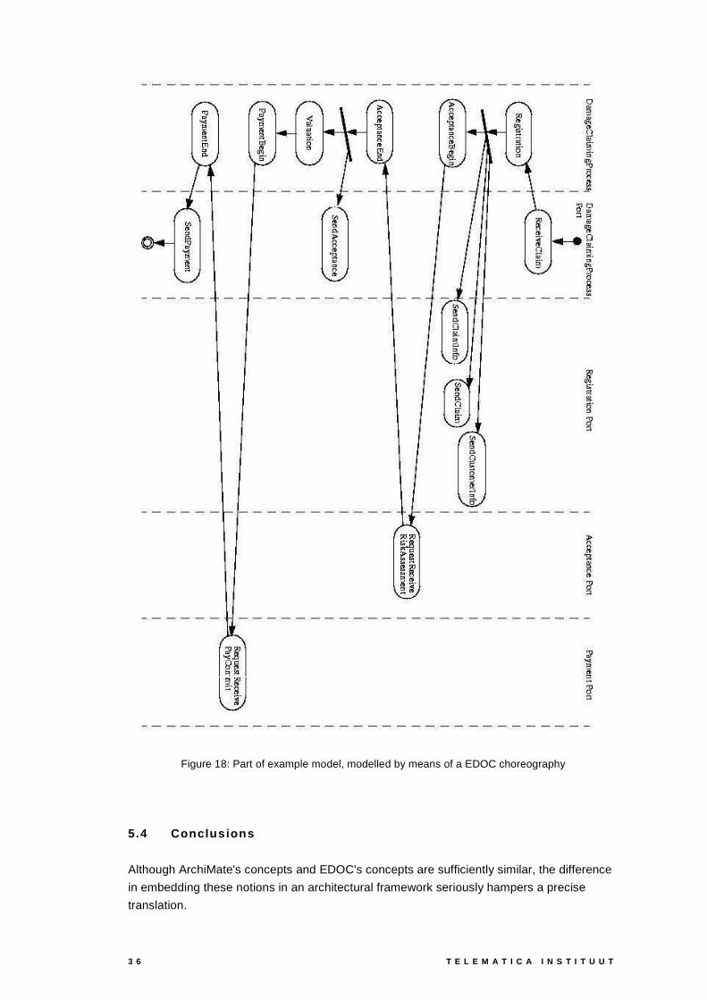
3 6 T E L E M A T I C A I N S T I T U U T
Figure 18: Part of example model, modelled by means of a EDOC choreography
5.4 Co n c l u s i o n s
Although ArchiMate's concepts and EDOC's concepts are sufficiently similar, the difference
in embedding these notions in an architectural framework seriously hampers a precise
translation.

A R C H I M A T E / D 2 . 2 . 3 B 3 7
ArchiMate has more similarity on all levels than EDOC. This is a positive influence of
ArchiMate's generic metamodel from which the metamodels for the three layers have been
derived.
ArchiMate has less similarity than EDOC has between its passive components and its active
components. In that respect ArchiMate is not (or less) object-oriented, where EDOC is
(more) object-oriented. But even EDOC discriminates between the passive and the active
components via the different terminology of events triggering activities and actions triggering
operations.
ArchiMate's model of the example remains more declarative than the corresponding EDOC
model, as no communication direction is indicated and as no splitting of an activity into pre
and post communication states. Our impression is that this phenomenon holds more
generally. Next to the present examples with a strong operational flavour it appears to hold
for more declarative examples as well. This makes EDOC models substantially more
technical than the corresponding ArchiMate models. Particularly for the business level this
might be considered as an advantage of ArchiMate over EDOC.

3 8 T E L E M A T I C A I N S T I T U U T
6 Business Process Modelling Notation
BPMN is one of the standards being developed by the Business Process Management
Initiative, BPMI (http://www.bpmi.org). BPMI is a not-for-profit organisation, which states as
its goals: (1) the specification of open standards for process design, and (2) the support of
suppliers and users of business process management techniques and tools. Many
organisation involved in business process modelling and management are involved in the
BPMI activities. Other standards that are being developed by BPMI include:
• The Business Process Modelling Language, BPML: an XML-based metalanguage for
the exchange of business process models.
• BPQL: a business process query language.
The BPMN standard (Business Process Management Initiative, 2003) specifies a graphical
notation that is to serve as a common basis for a variety of business process modelling and
execution languages. Mappings from BPMN to, among others, BPML and BPEL4WS
(Business Process Execution Language for Web Services) have been defined. Version 1.0
of the BPMN specification has appeared in August 2003. Examples of business process
notations that have been reviewed for this are UML Activity Diagrams, UML EDOC Business
Processes, IDEF, ebXML BPSS, Activity-Decision Flow (ADF) Diagrams, RosettaNet,
LOVeM and Event Process Chains (EPCs).
6.1 Fr am ew o r k BPMN
As the name already indicates, BPMN is restricted to the business layer, with a strong
emphasis on the behaviour aspect. The main purpose of the language is to provide a
uniform notation for modelling business processes in terms of activities and their
relationships. The ‘pool’, ‘lane’ and ‘artefact’ concepts offer limited possibilities for including
some structural and informational aspects associated with the business processes.
Businesslayer
Applicationlayer
Technicalinfrastructurelayer
Informationaspect
Behaviouraspect
Structureaspect
BPMN
Figure 19. Coverage of BPMN
6.2 Co n c ep t s /m et am o d el
Currently, BPMN only defines a concrete syntax, i.e., a uniform (graphical) notation for
business process modelling concepts. However, there is a formal mapping to the XML-
based business process execution language BPEL4WS. A formal metamodel for BPMN

A R C H I M A T E / D 2 . 2 . 3 B 3 9
does not (yet) exist. However, to give an overview of the language, we show our
interpretation of a metamodel of the main BPMN concepts in Figure 20.
Pool Lane
Entity
Event Activity Gateway
Task
Artifact
Dataobject
Anno-tation
Assosiation
Messageflow
Sequenceflow
Messageflow
Message flow
Figure 20. BPMN metamodel
An event in BPMN is defined as something that “happens” during the course of a business
process. These events affect the flow of the process and usually have a cause (trigger) or
an impact (result). This closely matches the business event concept in ArchiMate.
However, BPMN defines a large number of specialisations of the concept. The main
specialisations are start event, stop event and intermediary events, but several subtypes
of all of these exist. This is in agreement with the focus of BPMN on detailed process
modelling, which differs from ArchiMate’s goal, i.e., to model the overall structure of an
enterprise.
An activity is a generic term for work that a company performs. An activity can be atomic or
non-atomic (compound). In this sense, it most closely matches the generic business
behaviour concept in ArchiMate. Specialisations of the activity concept are process
(ArchiMate: business process), sub-process (ArchiMate: business process/function)
and task, defined as an atomic activity that is included within a process (ArchiMate:
business activity).
A gateway is used to control the divergence and convergence of sequence flow. Thus, it
will determine branching, forking, merging, and joining of paths. The gateway concept is
useful mainly for detailed process modelling, for which BPMN has been developed. BPMN
defines a large number of specialisations of the gateway concept. The junction relation in
ArchiMate, which is used to model, e.g., split or joins of triggering relations, can be seen as
an abstraction of the gateway concept. However, the gateway concept often also implies
behaviour. If this behaviour is relevant, a mapping to a business activity (with multiple
outgoing triggering relations, or followed by a junction) might be more suitable.
A pool is a “swimlane” and a graphical container for partitioning a set of activities from other
pools, usually in the context of B2B situations. A lane is a sub-partition within a pool and will
extend the entire length of the pool, either vertically or horizontally. Lanes are used to
organise and categorise activities. Pools and lanes can be used to group activities based on

4 0 T E L E M A T I C A I N S T I T U U T
arbitrary criteria. As such, they can be mapped to the grouping relation in ArchiMate.
However, they are most commonly used to represent the actors or roles that perform to
activities. In that case, they can be interpreted as the business actor or business role
concept in ArchiMate. The only relation that can be specified between pools is a message
flow. Placing activities within a pool or lane can be seen as a way to specify the
assignment between behaviour and roles/actors in ArchiMate.
BPMN defines three types of artifacts, which are not formally defined as concepts. An
annotation is a textual annotation that can be associated with any concept. There is no
separate concept for this in ArchiMate. A data object represents data that can be accessed
by activities, very similar to the business object in ArchiMate. Finally, a group artifact can
be used to group arbitrary concepts, in the same way as the grouping relation in ArchiMate.
A sequence flow is used to show the order that activities will be performed in a process.
The ArchiMate triggering relation can express this control flow in a quite similar way.
A message flow is used to show the flow of messages between two entities that are
prepared to send and receive them. In BPMN, two separate pools in the diagram will
represent the two entities (participants). In ArchiMate, the flow relation can be used to
express this.
An association is used to associate information with flow objects. Text and graphical non-
flow objects can be associated with the flow objects. Depending on the exact use, this is
represented by the access relation or the association relation in ArchiMate.
Table 5 summarises the BPMN concept mappings.

A R C H I M A T E / D 2 . 2 . 3 B 4 1
BPMI concept ArchiMate equivalent
Event Event
Activity
Business process/function
Gateway
Junction*
Sequence flow Triggering relation
Message flow Flow relation
Association Access relation;
Association relation
Pool Nam
eN
ame
Actor;
Role;
Grouping relation.
Lane
Nam
eN
ame
Nam
e
Nam
eN
ame
Nam
e
Actor;
Role;
Grouping relation.
Task
Business activity (specialisation of Business process)
Artifact
Generic concept, see specialisations below
Data object
Business object
Group artifact
Grouping relation
Annotation TextText
None
Table 5. Summary of BPMN mapping
6.3 Mo d el s
Figure 21 shows a part of our example model expressed in BPMN. Only the business layer
can be modelled: BPMN lacks concepts for modelling applications or technical infra-
structure. Services cannot be modelled either. The actors or roles that perform certain
processes or activities can be shown by means of pools.

4 2 T E L E M A T I C A I N S T I T U U T
Arc
hiS
uran
ce Registration Acceptance Valuation Payment
Clie
ntC
lient
Submitclaim
ClaimClaim
Receivedecision
1) senddamage form
2) sendnotification
Figure 21. Example model in BPMN
6.4 Co n c l u s i o n
The coverage of BPMN is restricted to the business layer. Moreover, there is a strong
emphasis on the behaviour aspect; actors/roles that perform the behaviour can be modelled
in a limited way by means of pools and lanes.
All the main BPMN concepts (except Annotation) have an equivalent in ArchiMate, while on
the other hand not all of the ArchiMate concepts have a counterpart in BPMN. However,
BPMN has a large number of more specific concepts, which are defined as specialisations
of the main concepts. This is in agreement with the objectives of the two languages: while
ArchiMate is designed to describe the high-level architecture of the whole enterprise, BPMN
focuses on the detailed description of business processes.
Currently, BPMN does not have a formal metamodel and the concepts and relations have
not been defined in a strict way. The emphasis is on the graphical notation of the language.

A R C H I M A T E / D 2 . 2 . 3 B 4 3
7 ARIS
7.1 Fr am ew o r k Ar i s
Aris is the name of a prominent tool for process modelling as well as the name
conventionally used for the method and concepts at the core of it. Unless explicitly stated
otherwise, it’s the latter usage we refer to throughout this chapter. Our description of the
framework and the concepts is based mainly on version 6.2 of Aris Methods (IDS Scheer
AG, 2003), which comes with the Aris Toolset.
The concepts of ARchitecture of integrated Information Systems (ARIS) are developed
around 1980 and onwards by August-Wilhelm Scheer. The design is based on what he calls
‘an integration concept which is derived from a holistic analysis of business processes’.
Figure 22: Aris views
The components necessary to provide a full description of a business process are
procedures, events, products/services (statuses), processors, organizational units and
information technology resources [AM2003, p. 2-2]. In order to reduce the complexity of a
model entailing all of these aspects, Aris discerns individual views that represent separate
modelling and design aspects: products and services, functions, the organization and the
(ICT) resources (treated as data). To this a fifth view is added, in which the concepts from
the views are linked together: the control view. These views usually are depicted in the form
of a house.

4 4 T E L E M A T I C A I N S T I T U U T
Figure 23: Aris Framework
For each of these views three levels of description are used, along the lines of the software
development life cycle. These are the requirements definition level, the design specification
and the implementation level, respectively. Depicted in the Aris house this gives us the
following framework.
The projection on the aspects and layers of Archimate shows that the greater part of all the
‘boxes’ is being served by the views. We even have to split the projection, because of the
special nature of the control view, where all objects are reused to model processes.
Businesslayer
Applicationlayer
Technicalinfrastructurelayer
Informationaspect
Behaviouraspect
Structureaspect
Control view
Businesslayer
Applicationlayer
Technicalinfrastructurelayer
Informationaspect
Behaviouraspect
Structureaspect
Function view
Productview
Organizationview
Dataview
Figure 24: Coverage of Aris views
7.2 Map p i n g o f t h e Ar i s o b j ec t s t o t h e Ar c h i m at e c o n c ep t s
Considering the very large number of concepts (‘objects’) in Aris it seemed advisable to
start with the Archimate concepts and map them upon the Aris concepts rather than the
other way around. This way we get a good grasp of the completeness of Aris with respect to
Archimate. We don’t get a good view upon the completeness of Archimate with respect to
Aris though. This is not a problem, for the completeness of Archimate follows from the
purposes set for the ArchiMate language. Especially the inter-domain communications are
leading for the scope of Archimate.
Although we take the ArchiMate concepts as a starting point and identify Aris counterparts
we choose to present the results in reverse order. This is done to help those not familiar
with Aris to get some understanding of the structure of the conceptual language of Aris. We
leave out the object types of lesser importance and those too far outside the domain of
Archimate. For ease of reference we refer to the five views in our discussion of the Aris
objects. We conclude the discussion of each layer with a wrap-up table from the perspective
of Archimate.

A R C H I M A T E / D 2 . 2 . 3 B 4 5
7.2.1 Co n c ep t s o f t h e B u s i n es s l ay er
In the function view we find two object types: function and target, that refer to the business
layer. They each can be hierarchically ordered, in the function diagram and the objective
diagram respectively.
Function is defined as a technical task or activity performed on an
object in support of one or more company objectives1. This is broader
than the BUSINESS FUNCTION, it also seems to encompass the concepts
BUSINESS PROCESS and BUSINESS INTERACTION. The specializations of
these concepts in Archimate can be modeled in Aris as so called
variants.
The data view gives us a lot of already well-known concepts. Next to specific Aris object
types Aris relies on existing modeling techniques such as ERM (and it’s dialects) and DTD
(XML). Aris also has implemented UML, but all of its models are located in the control view
(there would be a strong case to locate the class diagram in the data view).
The obvious matching of BUSINESS OBJECT would be with a class. The main object types
specific for Aris that match to Archimate concepts are: technical term, cluster and
information carrier.
An information carrier represents a means to store information. This
may be accomplished in the form of card files, forms or files on a
computer. This corresponds with REPRESENTATION.
Also important: data cluster. A cluster represents the logical view on a
collection of entity types and relationship types of a data model that is
required for the description of a complex object. Being the logical view on
a complex object the data cluster is best mapped onto the BUSINESS
OBJECT.
The organization view describes the static structure of the organization.
An organizational unit is defined as the performer of the tasks that
must be performed in order to attain the business objectives. It
corresponds with BUSINESS ACTOR.
On a more detailed level we see the object type position, defined as
the smallest organizational unit in a company. It is assigned to
employees (persons). In general, the authorizations and
responsibilities of a position are defined in position description. This
object type also corresponds with BUSINESS ACTOR.
1 Texts in italics are quotes from AM2003.
Function
Cluster
Information carrier
Organizationalunit
Position type

4 6 T E L E M A T I C A I N S T I T U U T
The control view, mostly referred to as the process view, is the place where the relations
between the various views are forged. The most pervading model type is the event-driven
process chain (EPC), which depicts the procedural sequence of functions and along with
that relates the functional view to the data view.
The two central object types are function and event. The latter is
defined as the existence of a state of an information object that is
pertinent for business management and which controls or influences
the subsequent procedure of the business process. Events trigger
functions and are the results of functions. Unlike a function, which is a
time-consuming occurrence, an event is related to one point in time.
The event corresponds with BUSINESS EVENT.
In relation to BUSINESS ROLE Aris presents the role diagram, not an object type, but having
semantics nevertheless according to the description. It is a still unclear how this will map in
a methodically sound manner. Looking for an alternative, the object type to be considered is
the person type (employee type), which represents the typification of individual persons,
which have the same characteristics. These characteristics may refer to similar
authorizations and responsibilities, for example. Department heads or foremen, for example,
have to follow rules and fulfill responsibilities, which – in case a corresponding type exists –
need to be defined only once.
A candidate for BUSINESS COLLABORATION is difficult in Aris too. One might
think of the object type group, defined as the representation of a group
of employees (persons), which are working together for a specific period
of time (project group), for example. The main difference with
organizational unit is the temporal nature of the group, hence the
proposed matching.
The process view also presents us
a model, which equals the concept
BUSINESS INTERFACE: the product
allocation diagram. In it so-called
variants can be used to model
different ways of delivering
services. See figure to get an idea.
The concepts ORGANISATIONAL
SERVICE and PRODUCT can be
rather straightforwardly mapped
onto the objects service and
product (on a higher level of
abstraction also occurring as
product/service); these objects
are described in the
product/service view. They are
defined as: a product/service is performed in the course of a value-added process. It is the
result of a human act or a technical process. A product/service can represent either a
Marketing instrument
Distributionchannel
Service
Need
Performancecharacteristic
Client
Event
Person type
Group

A R C H I M A T E / D 2 . 2 . 3 B 4 7
service or a product. A product can be a consumable product, a material type, an operating
resource type, a technical operating supply type or a packaging material type (these
specializations all have there own graphical representation and semantics). A service is an
intangible product that is produced and consumed simultaneously.
VALUE presents another problem. A related object type might be key
performance indicator instance, defined as an indicator or a key
indicator for measuring a degree of goal accomplishment. It can contain
a plan value, an actual value and a target value. Another candidate is
need, which describes a person's feeling of deficiency, which is to be
dispelled. A need stands at the beginning of a purchasing decision process. If the person is
faced with a product that is likely to satisfy his need, a demand arises.
MEANING has the object type knowledge category for a closely matching
counterpart. Occurrences of this object type categorize all kinds of
knowledge, including the knowledge that is documented. Like MEANING
knowledge is seen as content, different from the documents that record it.
Taking all this into consideration we present the following mapping as a starting point for
further study.
Archimate concept Aris object Remarks
Business actor Organizational unit,
position
Business collaboration Group This object type has a structural nature,
as opposed to the structural/behavioural
nature of the COLLABORATION (see
remarks on ROLE)
Business event Event
Business function Function
Business interaction Function
Business interface Service variant
(product allocation
diagram)
Business object Entity (type) (ERM);
data cluster
Entities are real or abstract things that
are of interest for those tasks in a
company that are currently under
consideration. If entities of the same type
are grouped into sets, they are called
entity types.
Data clusters represent complex objects
(i.e. objects that are readily broken
Keyperformance
indicatorinstance
Knowledgecategory

4 8 T E L E M A T I C A I N S T I T U U T
Archimate concept Aris object Remarks
down, like ‘customer order’)
Business process Function
Business role Role diagram
Alt: Person type
Aris does not distinguish the role as an
object type, but the tool includes the
Role diagram, in which processes are
coupled with authorisations, knowledge
and positions or persons.
An alternative is presented by person
type. It has a stronger structural
connotation than ROLE, but might fit.
(Note that position also might be mapped
onto BUSINESS ACTOR.)
Contract Technical term Aris does not present a specific object
type for this concept. The generic
technical term can be used.
Meaning Information category
Organisational service Service
Product Product
Representation Information carrier
Value Need Not an exact match, but close enough
Table 6: Business concepts correspondence between ArchiMate and Aris
7.2.2 Co n c ep t s o f t h e ap p l i c at i o n l ay er
The main object type of the design specification in the function view is
the application system type. It is defined as a typification of individual
application systems which have exactly the same technological
properties. In addition to this two lower order object types are
distinguished: the module type and the IT function type. In the usage of
these object types shows, that mainly a functional view on applications is
intended. In this perspective these object types correspond with the
APPLICATION COMPONENT and COLLABORATION. It depends on the desired
granularity of the description which of the three suits best in a given
model. It also is possible to choose for the APPLICATION FUNCTION and the
APPLICATION INTERACTION; Aris doesn’t seem to
distinguish the internal behaviour from the artifact the
way Archimate does.
The data view contains as principal object type
relation: a description of an entity type (BUSINESS
Relation
Entity type
Attribute
Applicationsystem type
Module type
IT functiontype

A R C H I M A T E / D 2 . 2 . 3 B 4 9
OBJECT) using its attributes. It is a subset of the possible combinations of the value ranges
of the individual attributes. Following this definition we match this object type with DATA
OBJECT. The usage of this object type in the relations diagram supports this interpretation
(see figure). The data cluster is on the application layer represented by the view, which
groups the relations for it.
The product/service view gives us the information service, which is a
service that generates and provides information. Considering the
informational nature of the applications (components) in this context, it
can be matched to APPLICATION SERVICE. Following the line of argument
on BUSINESS INTERFACE the concept of APPLICATION INTERFACE can be matched to
information service variant.
Archimate concept Aris object Remarks
Application
collaboration
application system
type, module type, IT
function type
The COLLABORATION in this matching is
seen as specialization of COMPONENT. So
it can be modeled as one of the
mentioned object types in Aris.
Application component Module type Depending on the aspects stressed the
module type is to be considered
structural or functional. It is tenable that
the module as structural concept
encompasses it’s function.
Application function Module type See above
Application interaction Function No clear candidate, but it is not to far
fetched to think of a function that realizes
the service mentioned with APPLICATION
COLLABORATION.
Application interface Information service
variant
As in the business layer.
Application service Information service Specialization of product/service, which
is appropriate considering the
informational nature of the applications.
Data object Relation
Table 7: Application concepts correspondence between ArchiMate and Aris
7.2.3 Co n c ep t s o f t h e t ec h n i c al l ay er
The prominent object type in the functional view is the application system or
module: a single copy of an application system type (module type), which
can be uniquely identified, by its license number for example. Next to that we
see the program module, which is defined as any program file on a data
carrier obtained by the purchase of a license (e.g. an EXE file or a COM file). Programmodule
Applicationsystem
Informationservice

5 0 T E L E M A T I C A I N S T I T U U T
(Note: this definition seems inspired by the perspective of the product supplier; it doesn’t
account for programs that are constructed in-house.) Typifying program modules that have
exactly the same technological basis forms a program module type.
The data view gives us tables and files and the like. For mapping purposes
we primarily choose for table, which is used as a typification: a table
represents the typification of individual tables (specimen), which have exactly
the same logical structure. This object type can be considered as a
specialization of ARTEFACT (out ruling things like executables).
The organizational view contains several object types in the design specification that in
Archimate are located in the technical layer.
The implementation level gives us the network, defined as a specimen of
different network types that are available in a company in order to operate
properly on the IT level, and the hardware component, which is defined as
a specimen of different hardware component types that are available in a
company in order to operate properly on the IT level. Network equals
NETWORK, while hardware component corresponds with DEVICE.
Note: this interpretation is derived from the usage in the manual, as the
definitions in combination are circular and non-conclusive. As a counterpart
to the organizational unit we see a host of technical resources on the implementation level.
Most are not ICT-oriented, but refer to manufacturing, warehousing or transport. Archimate
doesn’t provide similar concepts. But that’s different for the ICT-related object types
network connection (type) and network node (type). They cover the concepts
COMMUNICATION PATH and NODE. Their definitions are as follows:
• Network connections are specimen of different network connection types that are
available in a company in order to operate properly on the
IT level. Network connections link network nodes to one
another.
• A network connection type represents the typification of
network connections, which have exactly the same
technological properties.
• Network nodes are specimen of different network node
types that are available in a company in order to operate properly on
the IT level In this case, one network node represents one access point
to a network to which hardware components can be connected.
• A network node type represents the typification of individual network
nodes, which have exactly the same technological properties.
Table
Network
Hardwarecomponent
Network nodetype
Network node
Network connection type
Network connection

A R C H I M A T E / D 2 . 2 . 3 B 5 1
Archimate concept Aris object Remarks
Artefact No generic object type is available.
Depending the nature a variety of object
types can be used: program modules,
lists, files, tables, etc.
Communication path Network connection
Device Hardware component
System software Operating system
(type)
Infrastructure interface service variant As with BUSINESS and APPLICATION
INTERFACE.
Infrastructure service service
Network Network
Node Network node
Table 8: Technology concepts correspondence between ArchiMate and Aris
7.2.4 Rel at i o n s h i p c o n c ep t s
Aris knows a wealth of connection types. Descriptive definitions seem to be lacking, though.
On the other hand, the usage in diagrams and between object types is exhaustively
described. Relying on usage and naming, several to many connection types can represent
any Archimate relationship concept. The table just illustrates the completeness of Aris.
One (possibly superfluous) remark: each connection type is restricted in its usage to certain
object types and certain model types. In some cases this makes quick modelling a little
troublesome.
Archimate concept Aris object Remarks
Access Accesses
(alternatively)
Aggregation Aggregates
Assignment Assigns, assigned to
Composition Consists of / is
component of
Grouping Encompasses /
belongs to
Junction Splits to But mostly is expressed by an operator
in the relevant connection

5 2 T E L E M A T I C A I N S T I T U U T
Archimate concept Aris object Remarks
Realisation Realizes
Specialisation Is generalisation /
specialisation of
Triggering Triggers
Use Uses
Table 9: Relationship concepts correspondence between ArchiMate and Aris
7.3 Mo d el s
In this paragraph we present a translation of our example model in Aris. The presentation in
our diagram is fictitious, as Aris uses several model types to model all connections and
objects. But every connection in the diagram is supported by Aris, be it not in one model.
The repository takes care of that. The connections we for this reason inserted in our overall
diagram are dotted.
To be a ‘real’ Aris model, it would consist of a number of diagrams. Most of the objects
would be defined in the data, function, organization and product views respectively. The
interconnections would be defined in the control view, reusing the objects. So, the model
presented is to be considered as mainly a combination of various diagrams from the control
view.
For the sake of readability we present the diagram on its own page.

A R C H I M A T E / D 2 . 2 . 3 B 5 3
Infrastructure
External infrastructure services
Application components and services
Roles and actors
External application services
External business services
Damage claiming process
Claimsadminis tration
Claimsadminis tration
service
Customeradministration
service
Customeradministration
Claiminformation
service
delivers
Riskassessment
Paymentservice
Riskassessment
service
Financialapplicat ion
Mainframeinterface
Claim fileservice
uses
uses
uses
Customer filesservice
uses
Event1 Acceptance PaymentRegistrat ion ValuationEvent2 Event3 Event4 Event5Claim
Claim filezSer ies
mainframe
DB2
Sun Blade
iPlanet appserver
Riskassessment
EJB
Claimsadminis tration
Claimsadminis tration
service
Customeradministration
service
Customeradministration
Claiminformation
service
delivers
Riskassessment
Paymentservice
Riskassessment
service
Financialapplicat ion
Mainframeinterface
Claim fileservice
uses
uses
uses
Customer filesservice
uses
Claimregistration
service
Customerinformation
service
Claimspaymentservice
InsurerInsurant
Claim data
client Archisurance
Figure 25: Example model, modelled by means of Aris

5 4 T E L E M A T I C A I N S T I T U U T
7.4 Co n c l u s i o n
This first and somewhat superficial exploration suggests that a complete or at least almost
complete match between Aris object types and ArchiMate concepts can be construed.
It struck us, that the three life cycle stages (requirements definition, design specification and
implementation) contained roughly the object types that Archimate positions on the three
layers of analysis. This suggests that there is more to the Aris levels than pure life cycle. A
further exploration of this supposition is beyond the scope of this paper.
A lot of the Aris object types are defined in a very pragmatic way. This made it hard to make
the comparison on the basis of the definitions alone. Usage in models, examples and
possible relations had to be taken into account to come to conclusions. Therefore, the
proposed matchings have to be considered as preliminary.

A R C H I M A T E / D 2 . 2 . 3 B 5 5
8 Conclusions
The goal of this document is compare the ArchiMate language with important standards and
languages. To this purpose, ArchiMate is compared with UML, RM-ODP, the UML EDOC
profile, BPMN and Aris. Comparing different languages is sometimes like comparing apples
and oranges. Unambiguous statements about which is the “best” language are impossible.
After all, this would suggest some kind of objective “measuring stick” with which languages
can be compared. At present, most “accepted” languages have matured to a comparable
level. While emphasising different aspects, the core concepts are more or less covered by
each language. Obviously, the concepts are not exactly defined in the same way for each
language. However, origin and evolution of the languages appears to be the reason for
differences rather than the supremacy of one certain concept definition over another.
Avoiding the pitfall of trying to determine the superiority of one language over another leads
to a more pragmatic comparison of languages. After all, a language that covers a certain
context uses specific language concepts and rules and is used for a certain purpose.
Comparing languages with respect to the underlying framework, concepts and an example
model turns out to give a good feel and insight into the differences between languages.
With respect to framework comparison we conclude that the only aspect that is not covered
by most languages is the informative aspect of ArchiMate, which describes concepts such
as product, value and meaning. Only Aris appears to have a counterpart of this aspect with
its data and control view, while RM-ODP covers some of it by its objective concepts and,
possibly, the ‘policy’ concepts. Additionally, most other languages either cover only certain
‘domains’ (e.g., architectural layers) of an enterprise, or they are aimed at more detailed
models. For instance, the RM-ODP enterprise viewpoint covers the business layer of the
ArchiMate framework, but other RM-ODP viewpoints are needed to describe the application
and technological layers. The business process modelling initiative BPMN obviously covers
the business layer quite well but completely neglects the application and technology layers.
Finally, UML and EDOC cover all layers with respect to the behavioural and structure level
but differ from ArchiMate mainly with respect to the required detail in modelling.
In most cases, a high-level mapping from the other languages to ArchiMate concepts can
be made. Obviously, extensive and detailed languages or tools such as UML and ARIS
provide many detailed concepts and a one-to-one correspondence is not possible. More
specific concepts can only be mapped to specializations of ArchiMate concepts, or have no
equivalent in ArchiMate.
To our surprise, other languages often lack a formal metamodel, a notation or even both.
Especially if no notation has been defined, in practice it is hard to find models expressed in
these languages. For instance, actual RM-ODP models hardly exist. For the comparison of
concepts, not only their definition is relevant, but also their context, i.e., the concept to
which they are related. Having a well-defined metamodel supplies this in an unambiguous
way. For RM-ODP and BPMN we have tried to retrieve a metamodel from the
documentation. The lack of a well-defined metamodel is also related to an ambiguous

5 6 T E L E M A T I C A I N S T I T U U T
definition of relations. Compared to ArchiMate the relation concepts, in particular the
relations between domains, are often weakly defined in the other languages
ArchiMate is strongly biased towards abstracting from technical details - such as, when
exactly an activity or communication takes place, or about the precise direction of
communication. In this respect, ArchiMate is more declarative/managerial and less
imperative/operational. This observation is not only based on the comparison between
ArchiMate and UML - in this case it does not seem a real surprise - but it is also based on
the comparison with the architectural frameworks EDOC (and therefore RM-ODP) and
ARIS. Even the business process modelling language BPMN, although remaining on the
global business level, invites one to express more operational details than ArchiMate does,
like discriminating between sending and receiving - instead of (more neutrally)
communicating.
This is reflected in the expression of the example model in the different languages. The
example model provides exactly the type of integrated models for which ArchiMate is
intended. Detailed modelling of specific aspects is left to specialised languages. The relation
between aspect and domains is of focal interest to ArchiMate. Although ARIS appears to
result in a similar model, all other languages considered can model only parts of the model.
Especially with respect to the overall coherence the detailed languages such as UML and
EDOC require some (forced) ingenuity to obtain these types of integrated models.
UML was also used to illustrate the approach to use ArchiMate as an “umbrella language” to
link more detailed models in other languages, in this case different UML diagrams. In this
way, ArchiMate is used to guard and check the desired cross-diagram consistency still
lacking in UML.
In summary, we conclude that ArchiMate measures up to existing and accepted languages
or tools for integrated modelling purposes. ArchiMate distinguishes itself from most other
languages by its well-defined metamodel, concepts and, most importantly, its relations. The
abstraction level of ArchiMate simplifies the construction of integrated models, where most
languages appear to persuade architects to detailed modelling. Although detailed modelling
of most aspects also can be performed in ArchiMate. We think that using ArchiMate, as an
“umbrella language” is very useful. This approach has been applied to UML diagrams quite
successfully.

A R C H I M A T E / D 2 . 2 . 3 B 5 7
References
Buuren, R. van (ed.). (2004). Architecture Language Reference Manual, ArchiMate
deliverable D2.2.2b, Version 2.5, Dec.
Business Process Management Initiative. (2003). Business Process Modeling Notation.
Working Draft (1.0), Aug. http://www.bpmi.org.
Duddy, K., Gerber, A., Lawley, M., Raymond, K. & Steel, J. (2003). Model Transformation: A
Declarative, Reusable Patterns Approach. In M.W.A. Steen & B.R. Bryant (eds.),
Proceedings 7th IEEE International Enterprise Distributed Object Computing
Conference (EDOC 2003), Brisbane, Australia, IEEE Computer Society, Sept.,
pp. 174-185.
Domínguez, A., Rubio, L., & Zapata, M.A. (2002). Mapping Models Between Different
Modeling Languages. In Proceedings Workshop on Integration and
Transformation of UML Models (ECOOP’2002), pp. 18-22.
Goulão, M. & Brito e Abreu, F. (2002). Bridging the Gap Between Acme and UML 2.0 for
CBD. In ������������� �������������������������������������������
����� ������������������������ ������������������������
���� ���������
Iacob, M.-E., H. Jonkers (ed.), M. Lankhorst, R. van Buuren, L. Groenewegen, K.-H.
Cheung, M. Bonsangue, (2002), State of the Art in Architecture Concepts and
Description, ArchiMate/D2.1, Dec.
IDS Scheer AG. (2003). Aris Methods, Version 6.2.
Jonkers, H. (ed.). 2003. Concepts for Architectural Description, ArchiMate deliverable
D2.2.1, Version 2.5, Dec.
Koehler, J., Hauser, R., Kapoor, S., Wu, F. & Kumaran, S. (2003). A Model-Driven
Transformation Method. In M.W.A. Steen & B.R. Bryant (eds.), Proceedings 7th
IEEE International Enterprise Distributed Object Computing Conference (EDOC
2003), Brisbane, Australia, IEEE Computer Society, Sept., pp. 186-197.
ITU-T X.911 (10/2001), International Standard ISO/IEC 15414, Information Technology –
Open distributed processing - Reference Model – Enterprise language (RM-
ODP)
ITU-T X.902 (11/1995) International Standard ISO/IEC 10746-2, Information Technology,
Open Distributed Processing - Reference Model: Foundations
Object Management Group. (2002). UML Profile for Enterprise Distributed Object
Computing Specification. www.omg.org/docs/ptc/03-09-05.pdf.
Object Management Group. (2003a). Unified Modeling Language (UML) Specification:
Infrastructure. Version 2.0. www.omg.org/docs/ptc/03-09-15.pdf.
Object Management Group. (2003b). UML 2.0 Superstructure Specification.
www.omg.org/docs/ptc/03-08-02.pdf.