Embed Size (px)
Citation preview

International Congress of Refrigeration 2007, Beijing.
ICR07-B2-1565
Controlling a 2-phase CO2 loop using a 2-phase accumulator
Bart VERLAAT National Institute for Nuclear Physics and High Energy Physics (NIKHEF)
P.O. Box 41882, 1009 DB, Amsterdam, the Netherlands
Email: [email protected]
Telephone: +31 20 592 2095/ Fax: +31 20 592 5155
ABSTRACT
Mechanically pumped 2-phase fluid loops often have the problem of insufficient sub-cooling to operate the pumps
without cavitation. This paper describes the use of 2-phase accumulators for controlling CO2 loops to obtain forced
sub-cooling and accurate evaporator control. The technique of using 2-phase accumulators for loop control was first
applied in satellite cooling.
Two accumulator controlled loops have been successfully developed at NIKHEF. One CO2 loop for cooling the AMS
particle detector which will study cosmic radiation onboard the International Space Station and a second CO2 loop is
developed for cooling the LHCb-VELO particle detector which will study CP-violation at the CERN laboratory in
Geneva (Switzerland).
A 2-phase accumulator has the advantage of controlling the evaporator and condenser pressures independent of the
primary cooler temperature. It is therefore possible to create as much sub-cooling for the pump as desired. It is even
possible to operate the loop in single phase, a feature which turns out to be very convenient during start-up and
cooling-down procedures. A 2-phase accumulator for evaporator pressure control in combination with an internal heat
exchanger between the liquid feed and the 2-phase return line creates a very stable evaporator with a guaranteed
evaporation at low vapor qualities. In this way the evaporator heat transfer can be tuned and evaporator dry-out is
prevented.
1. INTRODUCTION
The semiconductor silicon tracking detectors of the Alpha Magnetic Spectrometer (AMS) (Borgia, 2005) on the
International Space Station (ISS) and the LHCb-VErtex LOcator Experiment (VELO) (LHCb collaboration, 2001) at the
CERN’s Large Hadron Collider (LHC) require accurate thermal control of the silicon sensors. The readout electronics
of the sensors produce the heat which a cooling system should remove. Construction material used inside silicon
detectors must be of low mass and tolerant to ionizing radiation. To suppress radiation damage of the silicon detectors,
the silicon must be kept cold to sub-zero temperatures at all times (Rose collaboration, 1999). A silicon tracking
detector consists of multiple silicon sensors which are uniformly spread over the detector volume. All the silicon
sensors need to have equal temperatures within 1 or 2 degrees to avoid thermal stresses. The discussed requirements for
a silicon detector cooling system such as: low mass, multiple heat sources, small temperature gradients and radiation
resistance, give design constraints to the cooling system which are different from conventional cooling systems.

International Congress of Refrigeration 2007, Beijing.
The requirements of the cooling system for the
LHCb VELO detector have led to the use of CO2
as evaporative cooling fluid (Boer Rookhuizen et
al. 1999). CO2 was selected as coolant because of
the radiation hardness and the proper 2-phase
temperature range. Feasibility tests have shown
excellent thermal performance of CO2 in small
diameter evaporators, which is a welcome feature
for a cooling system were low mass is required.
The development of CO2 evaporative cooling at
NIKHEF was simultaneous to the developments
of CO2 cooling in the commercial refrigeration
industry.
The AMS Silicon Tracker required a cooling system which can keep the evaporator section at a constant temperature. In
space the background temperature is around 4 Kelvin, heat can be rejected to space from radiator panels. These
radiators have a fluctuating temperature due to the changing exposure to the sun and earth.
At NIKHEF a mechanically pumped CO2 loop was developed for the cooling of the AMS Silicon Tracker. This cooling
system is named AMS-Tracker Thermal Control System (AMS-TTCS), (Verlaat et al. , 2002). The temperature in the
evaporator is controlled by a 2-phase accumulator control mechanism which is used in capillary pumped loop systems,
which were under development for satellite cooling (TPX Space Shuttle experiment), (Delil, et al. 1997). The 2-phase
accumulator keeps the pumped loop at a constant system pressure. The evaporator temperature is therefore fixed, as
long as saturated liquid is flowing through it. The temperature variation in the sub-cooled liquid from the condenser is
heated by the internal heat exchanger. In this way it is possible to keep the evaporator constant at a fluctuating heat
sink, without additional heating or mechanical control. This is important in space, because power is limited and
mechanical actuators have a too large risk of failure.
The method of controlling a 2-phase loop
with a 2-phase accumulator as it was done
in the AMS-TTCS is well suited for the use
in the cooling cycle of the LHCb-VELO
detector. This cooling system is named
VELO Thermal Control System (VTCS)
(Verlaat, 2005). The cold radiator of the
AMS-TTCS is replaced by a conventional
refrigeration system. This combination
allows temperature control of the VELO
detector at a large distance (~50m), without
any control actuators in the radiation area,
resulting in a complete passive evaporator
system. This paper describes the design and
testing of a 2-phase accumulator controlled
loop (2PACL) developed for the VELO
Thermal Control System.
Figure 1.1: The AMS experiment on the ISS
27 VELO modules Evaporator with 27
parallel connections
Figure 1.2: The LHCb VErtex LOcator
Beam-pipe

International Congress of Refrigeration 2007, Beijing.
2. THE 2-PHASE ACCUMULATOR CONTROLLED LOOP FOR THE VTCS
2.1 PRINCIPLE OF A 2-PHASE ACCUMULATOR CONTROLLED LOOP (2PACL)
Figure 2.1 shows the schematic diagram of the 2PACL as it is applied in the VELO. A mechanically pumped CO2 loop
is cooling the VELO detector by evaporating low quality CO2 (9-10). The vapor is condensed by a chiller with R404a
as refrigerant (13-1). The condensed liquid is pumped by a liquid pump back towards the detector (2-3-8). The
evaporator and condenser work at the same pressure, because the pressure drop of the vapor return line is low. The CO2
pressure is controlled by the 2-phase accumulator (14) which is parallel connected between the condenser and the pump
(1). The accumulator contains a saturated CO2 liquid-vapor mixture. The temperature of the saturated mixture in the
accumulator is regulated, controlling the accumulator pressure hence the condenser and evaporator pressure. The
pressure regulation of the accumulator is a combination of heating and cooling. An electrical heater is evaporating
liquid CO2 causing the pressure to increase, an evaporator branch of the primary R404a chiller is condensing CO2 vapor
causing the pressure to decrease.
In order to ensure sub-cooling of the CO2
before the liquid pump, the accumulator
temperature must be above the condenser
temperature. The sub-cooled state will
prevent the pump from cavitation, a
common problem in mechanically pumped
2-phase loops. The sub-cooled liquid is
however too cold to be injected into the
evaporator, because evaporators require
saturated liquid. To heat the liquid up to
saturation, a heat exchanger between the
liquid inlet (4-5) and vapor outlet (11-12)
of the evaporator is used. The absorbed
heat in the evaporator is used to heat the
sub-cooled flow so no extra heat is needed.
Figure 2.2 shows the schematic of figure
2-phase
gas
R404a chiller
1
2-phase
2-phase
liquid
2-phase
Con
den
ser
Eva
pora
tor
Concentric tube
Pump
Res
tric
tion
Accumulator
liquid
2
3 4
10
9
8765
1112
14
13
2-phase
gas
Transfer lines(Ca. 50m)Cooling plant area VELO area Inside VELO
Heater
2-phase
gas
R404a chiller
11
2-phase
2-phase
liquid
2-phase
Con
den
ser
Eva
pora
tor
Concentric tube
Pump
Res
tric
tion
Accumulator
liquid
22
33 44
1010
99
88776655
11111212
1414
1313
2-phase
gas
Transfer lines(Ca. 50m)Cooling plant area VELO area Inside VELO
Heater
Figure 2.1: Schematic of the VELO Thermal Control System
Figure 2.2: Operation of a 2PACL in the P-h diagram of CO2
-450 -400 -350 -300 -250 -200 -1505x 102
103
104
2x 10⁴
h [kJ/kg]
P [k
Pa]
-40°C
-30°C
-20°C
-10°C
0°C
10°C
0.2 0.4 0.6
Te rtia ry VTCS in P-H dia gr am
1
23
4
56
7
Accumulator pressure = detector temperature
Internal heat exchanger brings evaporator pre-expansion per definition right above saturation(3-5)=-(10-13)
Saturation line
Capillary expansion brings evaporator in saturation
Detector load (9-10)
1013
9
8
53
1
Pump is sub cooled
-450 -400 -350 -300 -250 -200 -1505x 102
103
104
2x 10⁴
h [kJ/kg]
P [k
Pa]
-40°C
-30°C
-20°C
-10°C
0°C
10°C
0.2 0.4 0.6
Te rtia ry VTCS in P-H dia gr am
1
23
4
56
7
-450 -400 -350 -300 -250 -200 -1505x 102
103
104
2x 10⁴
h [kJ/kg]
P [k
Pa]
-40°C
-30°C
-20°C
-10°C
0°C
10°C
0.2 0.4 0.6
Te rtia ry VTCS in P-H dia gr am
1
23
4
56
7
Accumulator pressure = detector temperature
Internal heat exchanger brings evaporator pre-expansion per definition right above saturation(3-5)=-(10-13)
Saturation line
Capillary expansion brings evaporator in saturation
Detector load (9-10)
1013
9
8
53
1
Pump is sub cooled

International Congress of Refrigeration 2007, Beijing.
2.1 in the P-h diagram of CO2. The indices of the diagram correspond to the nodes in figure 2.1. The exchanged heat in
the internal heat exchanger is the enthalpy difference of node 3 and 5. As a minimum this heat must have been absorbed
in the evaporator (9-10). If the evaporated heat is sufficient to overcome the sub-cooling, the evaporator inlet (Node 9)
is 2-phase and close to the saturated liquid curve, otherwise the inlet of evaporator remains sub-cooled causing
degraded heat transfer.
A 2PACL does only require a controlled accumulator. The 2PACL condenser temperature may vary, as long as the
maximum temperature is lower than the accumulator set-point. The chiller may therefore run maximal cold, without
any chiller evaporator regulation. The 2PACL pump flow may be constant as well; a sufficient overflow of the pump
will make the system heat load independent and prevent the 2PACL against evaporator dry-out.
A useful feature of the 2PACL is the ability of turning the 2-phase loop into a single phase loop. Significantly
increasing the accumulator’s pressure will suppress any formation of vapor anywhere in the loop. This feature is very
useful at start-up. It is used as start-up procedure in both the AMS-TTCS and the LHCb-VTCS systems.
2.2 VELO THERMAL CONTROL SYSTEM DESIGN.
The cooling plant contains the chillers, the pumps, the accumulators and
valves. The detector with evaporator is away from the cooling plant and
situated in a hostile radiation environment which makes it inaccessible. The
transfer of cooling fluid from the plant to the evaporator is via a concentric
transfer tube. The liquid feed line is inside the vapor return line and bridges
the 50 meter distance from the plant to the evaporator. The transfer tube is
concentric so the environmental heat will only affect the return flow. The
concentric tube is the necessary internal heat exchanger to overcome liquid
sub-cooling.
The silicon wafers in the detector need to be kept cold at all times. This is
also required even if the detector is switched off. In paragraph 2.1 it was
discussed that a heat load is needed in the evaporator to overcome the
sub-cooling. If no sufficient heat load is available, sub-cooled liquid will
enter the evaporator and the accumulator is no longer able to control the
temperature of evaporator. The evaporator can become colder than the
accumulator set-point leading to an uncontrolled and too cold detector. The
transfer tube’s isolation is tuned such that enough heat from the
environment is entering the loop at all time to overcome the
sub-cooling, the evaporator does not need a heat load in this
case. The concept of environmental heat leak is chosen over
electrical heating, because of reliability issues.
The evaporator has flow restrictions to distribute the flow
evenly over the 27 parallel cooling connections. At start-up
these restrictions can cause large pressure drops in the system
when vapor has to pass through. At start-up it is also not
guaranteed that the pumps are primed with liquid. The pumps
are not self priming and they will not start up if there is no
Figure 2.3:VTCS CO2 plant
Figure 2.4: VTCS Evaporator Assembly

International Congress of Refrigeration 2007, Beijing.
liquid inside. A nice feature of the accumulator control is that the 2-phase loop can be turned into a single phase liquid
loop by heating-up the accumulator. The VTCS-accumulator will be heated to 27ºC prior to start-up. The pressure in the
loop is above the saturation pressure of the environment, causing the CO2 in the loop to be liquefied. The pump can
now start-up without problems and the restrictors are fed with liquid, keeping the pump head pressure low.
2.3 VTCS SIMULATION RESULTS.
A simulation model of the VTCS loop has been made to study the thermal equilibriums of the different operational
states in transient modes. Figure 2.5 shows the simulation results of several situations from start-up to cold operation.
The model calculates the energy and pressure balance of the nodes of figure 2.1. Environmental heat leak is included
and calculated between each node. Prior to start-up, the whole loop is at room temperature. It is not defined where the
liquid or vapor is situated. The start-up situation (A) in the P-h diagram is somewhere along the 20ºC isotherm in the
2-phase region. At start up the accumulator is heated to 27ºC and the system pressure increases to the corresponding
saturation pressure of 67 bar. The loop is still at room temperature and will be filled with liquid. Once the loop is filled,
the pump can be switched on. Sub-cooled liquid of 20ºC is now circulated and cooling from the primary R404a chiller
is not yet needed. The loop operates as situation “B” in the P-h diagram. Once liquid circulation is achieved the primary
chiller can be switched on. The accumulator is kept at high pressure so all the liquid will stay sub-cooled. In paragraph
2.1 it was discussed that the primary R404a chiller does not need any temperature regulation, therefore it will cool the
liquid flow to its minimum temperature. After cooling down in liquid mode the situation of “C” has been reached. The
pump flow will be about -40ºC, the evaporator (with liquid only!) is about -22ºC. The thermal gradient is due to the heat
leak of the transfer tube. After having cooled down the loop in liquid mode, the accumulator can be cooled down by the
primary chiller to the desired set-point of -30ºC. The system is now at situation “D”, which is indicated by the small
squares in figure 2.5. The unloaded evaporator (node 9-10) is now in the 2-phase region, so its temperature is now
controlled by the accumulator.
Once the situation of “D” is stabilized, the
detector power is switched on. In the
diagram this means that node 10 is moved
away from node 9, ending up in situation
“E”. The circuit of “E” also shows a
change of the sub-cooled temperature of
node 1 with respect to situation “D”. This
increase is due to the behavior of the
primary R404a chiller. An increased heat
load causes the compressor suction
pressure to increase, and hence the primary
evaporator pressure and temperature.
The simulation clearly shows the
independence of a varying sub-cooling. As
long as node 1 is on the left of the
saturation line, the system works properly.
The inlet of the evaporator (node 9) is
controlled to stay 2-phase and near the
saturation line, assuring the evaporator
being fed with a low quality 2-phase flow.
5 0 100 1 5 0 2 0 0 2 5 0 300 3 5 0 4005 x1 0 0
1 0 1
1 0 2
2 x1 0 2
h [kJ/kg]
P [b
ar]
-40°C
-20°C
0°C
20°C
40°C
0.2 0.4 0.6 0.8
VTCS start -up and operating cycles
1
3,5
810,13
1
3 5
8
9,10,13
1
3 5
8
9,10 131
3 5
89 10 13
CB
D E
A
5 0 100 1 5 0 2 0 0 2 5 0 300 3 5 0 4005 x1 0 0
1 0 1
1 0 2
2 x1 0 2
h [kJ/kg]
P [b
ar]
-40°C
-20°C
0°C
20°C
40°C
0.2 0.4 0.6 0.8
VTCS start -up and operating cycles
1
3,5
810,13
1
3 5
8
9,10,13
1
3 5
8
9,10 131
3 5
89 10 13
CB
D E
A
Figure 2.5: Simulation results of the VTCS model in the P-h diagram

International Congress of Refrigeration 2007, Beijing.
2.4 VTCS ACCUMULATOR DESIGN The accumulator must be partially filled with liquid at all operational situations. Figure 2.6 show the simulation results
of different liquid fillings in the accumulator as a function of accumulator volume for several fill ratios of the
accumulator and loop together. It shows that the 2 extreme accumulator liquid levels appear at the single phase cold (C)
for the minimum level and the loaded evaporator (E) for the maximum level (C and E are the situations of figure 2.5).
The chosen VTCS design parameters are indicated in the 2nd graph by a vertical dashed line; for a VTCS loop volume
of 8.8 liter a fill ratio of 575 gram per liter with an accumulator volume of 13.6 liter are sufficient to comply with all the
operational scenarios.
Figure 2.6: Accumulator liquid levels as a function of accumulator volume and fill ratios for a loop
volume of 8.8 liter.
0%
10%
20%
30%
40%
50%
60%
70%
80%
90%
100%
8.0 10.0 12.0 14.0 16.0 18.0 20.0 22.0 24.0
Accumulator Volume (L)
Liqu
id le
vel (
%)
.
0%
10%
20%
30%
40%
50%
60%
70%
80%
90%
100%
8.0 10.0 12.0 14.0 16.0 18.0 20.0 22.0 24.0
Accumulator Volume (L)
Liqu
id le
vel (
%)
.
0%
10%
20%
30%
40%
50%
60%
70%
80%
90%
100%
8.0 10.0 12.0 14.0 16.0 18.0 20.0 22.0 24.0
Accumulator Volume (L)
Liqu
id le
vel (
%)
.
0%
10%
20%
30%
40%
50%
60%
70%
80%
90%
100%
8.0 10.0 12.0 14.0 16.0 18.0 20.0 22.0 24.0
Accumulator Volume (L)
Liqu
id le
vel (
%)
.
VTCS Design
Loop fill ratio : 500 gram/liter
Loop fill ratio : 650 gram/liter Loop fill ratio : 725 gram/liter
Figure 2.9: Accumulator
cooling coils
Figure 2.8: Thermo siphon
heater
Figure 2.7: Accumulators in
the VTCS plant
Loop fill ratio : 575 gram/liter
International Congress of Refrigeration 2007, Beijing.
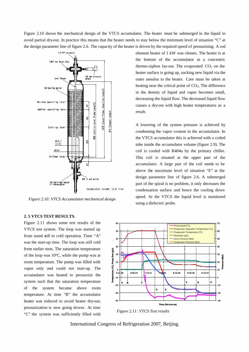
Figure 2.10 shows the mechanical design of the VTCS accumulator. The heater must be submerged in the liquid to
avoid partial dry-out. In practice this means that the heater needs to stay below the minimum level of situation “C” at
the design parameter line of figure 2.6. The capacity of the heater is driven by the required speed of pressurizing. A rod
element heater of 1 kW was chosen. The heater is at
the bottom of the accumulator in a concentric
thermo-siphon lay-out. The evaporated CO2 on the
heater surface is going up, sucking new liquid via the
outer annulus to the heater. Care must be taken at
heating near the critical point of CO2. The difference
in the density of liquid and vapor becomes small,
decreasing the liquid flow. The decreased liquid flow
causes a dry-out with high heater temperatures as a
result.
A lowering of the system pressure is achieved by
condensing the vapor content in the accumulator. In
the VTCS accumulator this is achieved with a coiled
tube inside the accumulator volume (figure 2.9). The
coil is cooled with R404a by the primary chiller.
This coil is situated at the upper part of the
accumulator. A large part of the coil needs to be
above the maximum level of situation “E” at the
design parameter line of figure 2.6. A submerged
part of the spiral is no problem, it only decreases the
condensation surface and hence the cooling down
speed. At the VTCS the liquid level is monitored
using a dielectric probe.
2. 5 VTCS TEST RESULTS.
Figure 2.11 shows some test results of the
VTCS test system. The loop was started up
from stand still to cold operation. Time “A”
was the start-up time. The loop was still cold
from earlier tests. The saturation temperature
of the loop was 10ºC, while the pump was at
room temperature. The pump was filled with
vapor only and could not start-up. The
accumulator was heated to pressurize the
system such that the saturation temperature
of the system became above room
temperature. At time “B” the accumulator
heater was reduced to avoid heater dry-out;
pressurization is now going slower. At time
“C” the system was sufficiently filled with
-40
-30
-20
-10
0
10
20
30
40
50
60
6:21:36 6:50:24 7:19:12 7:48:00 8:16:48 8:45:36 9:14:24
Time (hh:mm:ss)
Tem
per
atu
re (
ºC),
Pu
mp
flo
w (
g/s
)
.
-30
-20
-10
0
10
20
30
40
50
60
70P
ress
ure
(Bar
)
Pump liquid (ºC)Evaporator Saturation Temperature (ºC)Evaporator Temperature (ºC)
Massflow (g/s)Accu Pressure (Bar)Evaporator Pressure (Bar)
A B C
D E
F G H
Figure 2.11: VTCS Test results
Figure 2.10: VTCS Accumulator mechanical design

International Congress of Refrigeration 2007, Beijing.
liquid so the pump could start-up. The pump was rapidly cooling down while the evaporator temperature was staying
behind. The accumulator was maintained on pressure making the system cooling down in sub-cooled liquid state. At
time “D” the accumulator cooling started at a set-point of -25ºC. At time “E”, the evaporator was no longer sub-cooled;
the accumulator had taken over control of the evaporator’s temperature. At time “F”, the evaporator had reached the
set-point temperature of -25ºC and the detector power was switched on. At time “G” the accumulator set-point was
lowered to -30ºC, reaching the -30ºC evaporator temperature at time “H”. This was the minimum reachable evaporator
temperature with the VTCS test system, because the pump sub-cooling had become marginal. Note that the accumulator
and evaporator pressures were the same during the entire test.
3. CONCLUSION AND DISCUSSION
The 2-phase accumulator controlled loop (2PACL) method is a good solution for controlling mechanically pumped
2-phase loops. It can operate at a large dynamic evaporator pressure range and is virtually independent of heat load and
condenser temperature. The accumulator pressure is the only accurate controlled parameter in the system. This makes
the system robust, stable and easy to operate.
The 2PACL method is a good alternative for controlling the current secondary pumped loops. The accumulator method
can also be used for 2-phase loop systems which do not need controlled evaporators but only need to transfer heat from
A to B. One can think of an accumulator maintaining a slight over-pressure with respect to the pump sub-cooling, just
enough to avoid pump cavitation. Different types of accumulators can be considered, such as a spring acted bellow
accumulator with secondary 2-phase loading at the loop temperature, or an accumulator with a secondary fluid mixture
having slight over pressure properties to the loops working fluid. An active pneumatic controlled accumulator is also an
option. The LHCb-VTCS and the AMS-TTCS both use CO2 as working fluid, but the principle is expected to work
for any 2-phase fluid pumped systems.
4. REFERENCES
1. B.Borgia, 2005, The Alpha Magnetic Spectrometer on the International Space Station, IEEE Transactions on
Nuclear Science, Vol. 52, No. 6, p. 2786-2792
2. The LHCb Collaboration, 2001, The LHCb VELO Technical Design Report, CERN/LHCC note, 2001-0011
3. The ROSE Collaboration, 1999, R&D On Silicon for future Experiments, CERN/LHCC note, 2000-009
4. Boer Rookhuizen H. et al, 1999, Preliminary Studies for the LHCb Vertex Detector Cooling System, LHCb note,
99-046/VELO
5. Verlaat, B., Krijger, E., 2001, Performance Testing of the AMS TTCS CO2 Evaporator., NIKHEF note, ASR-T-
001/MT 01-02.
6. Verlaat, B. et al. 2002, Feasibility Demonstration of a Mechanically Pumped Two-Phase CO2 Cooling Loop for
the AMS-2 Tracker Experiment, Conference on Thermophysics in Microgravity, in the Space Technology &
Applications International Forum (STAIF-2002), Albuquerque, NM, USA
7. Delil, A.A.M. et al., 1997, In-orbit demonstration of two-phase heat transport technology - TPX II reflight,
European Space Agency, SP-400, p.355
8. Verlaat, B., Woering, A., Pauw, A., Delil, A.A.M., 2003, AMS-2 Tracker Thermal Control System: design and
thermal modeling of the mechanically pumped two-phase CO2 loop, AIAA Aerospace Sciences Meeting & Exhibit,
Reno, NV, USA, (AIAA-2003-0345)
9. Verlaat, B., 2003, Thermal Performance Testing of the VTCS Evaporator and VELO Module, NIKHEF note, MT
05-01.