Embed Size (px)
Citation preview

' .. '.
PROFILE
An aggressive design formanufacturing programhelped make this bird themost sophisticated heavyequipment transport planein the world
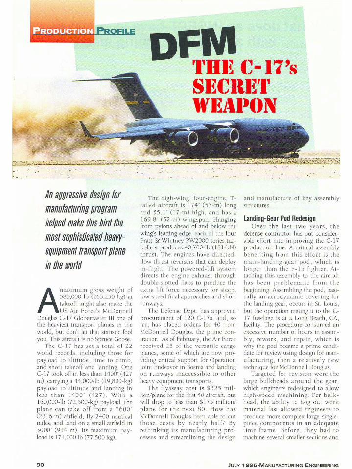
All1aXill1 Um gro ss weig ht of585, 000 Ib (263,250 kg) attakeoff might also make theUS Air For ce's McOonu cl l
Douglas - 17 Globcmasicr III one ofthe heaviest transport planes in theworld, but don 't let that Slati tic foolyou. This aircraft is no Spruce Goose.
Th e C- 17 has se t a tota l o f 22wor ld reco rds, including tho se forpayload to alt itude, time to climb,and sho rt takeoff and landing. OneC-17 took off in less than 1400' (427m), carrying a 44,000-lb C19,800-kg)payload to altitude and land ing inless th an 14 00 ' (4 2 7) . Wi t h a160 ,000-lb (n,500-kg) payload , thep lane can ta ke off from a 7600 '(23 16-m) airfield , fly 2400 nau ticalmiles, and land on a small airfield in3000 ' (9 14 111) . Its maximum payload is 171,000 lb (77,5 00 kg).
Th e high -wing, four-engine , Ttailed aircraft is 174 ' (53-m) longand 55 .1 ' (17 -m) hig h, and has a169 .S· (52-m) wingspan . Hangingfrom pylons ahead of and below thewing's leading edge, each of the [ourPratt & Whitney P\V200 0 series turbofans produces 40,700-lb (lSI-kN)thrust. The eng ines have directed now thru st reversers that can deployin- Flight . Th e po wer ed -l ift sys te mdirects the engine exhaust throughdouble-slotted fl aps to produ ce theextra lih force necessary fo r stee p,low-speed final approaches and shortrunways.
The Defense Dept . has approvedprocu rement of 120 - 17s, and , sofar , has placed o rde rs 1'01' 40 lromMcfx mn cll Douglas, the prime con tractor. As of February, the Air Forcereceived 25 of the versa ti le cargoplanes, some of which arc now providing critical support for OperationJoint Endeavor in Bosn ia and landingon ru nways ina ccessible to othe rheavy equipm ent transports.
Th e flyaway cos t is 53 25 mil lion/plane for the fi rst 40 airc raft . butwill drop to less than $ ] 75 million/p lane fo r the nex t SO. How hasMcDonnell Douglas been able to cutth ose costs b y nea r ly ha lf7 Byreth inking its manufacturing pro cesses and streamlin ing the design
and manufacture o f key assemblystru ctures.
Landing-Gear Pod RedesignOver th e las t two yea rs , the
defense cont racto r has put considerable effort into imp roving the C-17prod uction line. A critical assemblyben efi tin g fro m this effort is themain -landi ng-gear pod, which islonge r th an th e F- I 'j fighte r. Attaching this assembly to the aircraftha s been prob lc mut ic 11'0 111 th ebeginnin g. Assembling the pod , basically an aerodynam ic cove ring forthe landing gcar , occu rs in SI. Louis.but the operat ion mating it to the e17 fuselage is at ~ I Lung Beach, CA,facility, The procedu re consumed anexcessive num ber of hou rs in assembly , rework , and repai r , wh ich iswhy the pod became a pr ime cand idate for review using design for manufactur ing , th en a re lati vel y newtechnique for McDonn ell Douglas.
Ta rget ed for rev ision were thelarge bu lkh ead s around the gea r,which engineers redesigned to allowhigh-s peed mac hin ing. Per bu lkhead , the ability to hog out wo rkmate ria l fast allowed enginee rs toprodu ce more-com plex large singlepiece co m pon en ts in an adequa tetime fram e . Before , th ey had to
machin e several smaller sections and
90 JULY 1 99G-MANUFACTURING ENGINEERING

High-Spee d~Mra&h ,i,ning :oGuts Costs
McDonnell Douglas engineersreport high-speed machining
is the key to a number of production improvements made on theC- 17. Instead of building upassemblies, the process allowsthem to produce monolithic largeparts. The first high-speedmachining application was onbulkheads in the cargo door, andthe company has since adoptedthe practice for other sections ofthe aircraft.
An example is a landing gearbulkhead machined at McDonnellDouglas Aerospace (Sl Louis) ona Giddings and Lewis five-axisgantry mill. The machine has an 8X 35 ' (2 X 11 m) bed andopposing spindles that can runtwo jobs independently. This sizemachine was necessary toaccommodate the raw workmaterial, which was a 9 X 12.5 '(3 X 4 rn) 3S (89 mm)-thick7050-T7351 aluminum alloyplate pocketed on both sldes,
Engineers rough-machinedthe bulkhead with a T (51 mm)cutter at 200 sfm (6 1 m/min)
assemble them . The redesign redu cedde tail parts from 72 to 2 and fasten ers from 1720 to 35.
The redesi gn al so changed thepod from a three-pi ece co m positeskinned assembly to on e unit . Keyto red ucing assembly lime was th estep revising the attach men t method .Engineers rep laced the existing shearclip aua chrnc ms an d multiple fasten ers w ith a cle vis and drag- li n ka rrangemen t . Instead of riveting askate angle to the assembly's perimeter and to the aircraft fuselage. pro d uctio n workers now install bladeseals that need no auachmcnt to thefuse lage. whi ch reduces the numb erof holes they must d rill th rough thefuselage and makes it easie r to complet e the asse mbly's int erio r work .suc h as installing insu latio n.
Before the rede sign , pod sectionsarrived from St. Louis with composite cove r panels installed . In Long
and 10,000 rpm. The finalmachining process used a 3/4·(19 mm) cutter at 150 sfm (46m/min) and 13,500 rpm, andthen a 1/T (12 mrn) cutter at100 sfm (30 m/min) and 13,500rpm.
Machining one side of thebulkhead took four shifts, theother side two in a three-day period. McDonnell Douglas machining experts estimate the highspeed techn ique made the overallmachining time 15 X faster thanconventional machining. Accuracyalso was high. Out of the f irst 20tryout parts, engineers determined 17 were accurate enoughfor installation on the aircraft.
McDonnell Douglas officialsattributed the smooth transition tohigh-speed machining to the useof Integrated Product Teams. Inone case, a team received apiece of raw material that was toosmall. Because the McDonnellDouglas personnel involved wereworking closely with the materialsupplier, the team obtained newmaterial in hours, instead of days.
Beach . worke rs had to re move th epanels to install the required lightingand hydrau lic sys tems . They thenhad to reassemble the panels. Now .workers in St. Louis install the light ing and hydrauli cs systems . Matingthe landing gear pod assem bly to thefusel age ta kes less l ime . and thewho le s t ruc tu re has mo re rigidi lyand a bcu cr fit.
The p roj ect showed th e impo rta nce of Mc Don nell Do ugla s 'sIruc gra ted Project Team sysic rn,wh ich the company put in place toen sure th a t a ll necessary g roups .from accountan ts to suppliers andmain tenan ce sta ff. p rovid e in putabout de s ign and process cha nges .The landing-gear pod redesign project , for ins tance . involved bot h 51.Louis and Lon g Beac h pe rso nn e lfrom stru ctu ra l and syste ms engi neeri ng . an d too ling produ ct ion . aswell as s u p p lie rs and th e product
maint enance support organization .Si nce th e redesign project
invo lved teams in both cities , a betterway to communicate was esse ntial.The solutio n involved developing aCAD model of the development fixture previously used to mocku p theasse mbly and verify fit of all componen ts . Engineers in bot h 51. Lou isa nd Lo ng Beac h cou ld th en workwit h th e sa me elec t ro nic fixt u remod el and receive auto matic updateso f approved d esign cha nges . Th ise lec tronic design and veri ficatione li minated th e need to build twodevelopment fixtures, which hel pedreduce variation .
The cos t estimate for implement ing the improvements is $4 1 million .The results have led to major procedural cha nges that have cu t manufacturing time by 10 days and th atwill save more tha n $ 100 mill ion onthe remaining aircraft to he deliveredto the Air Force .
Eliminate Those FastenersAnother redesign that saved time
was a project revising the original air craft ceiling st ructure of rnatrixed aluminum hat-section beams. In the lirstplan es off th e assembly lines , engineers attached panels to the struc tureusing 24 adjustable rods . Fitting andtr imm in g th em aro un d th e ducts ,elect rical po wer centers, and avionicsra c ks wa s t im e -co nsum ing . T heredesign eliminated the ceiling structure , using existing aircraft components like the ventilation du cts andfluorescent light fixture s as support.Inst ead of using a hard auachme ntarou nd th e panel edges. engineersattached Vclcro-type Dual Lock stripsto allow fast attach men t and removalof panels and eliminate trimming .
Cos t of making the changes wasj us t over $400,000 , but the cos tavoidance with the new coc kpit ceiling is an estim ated $ 1,750.000 in the120-aircraft program . Moreover, theAir Force will requ ire less mai nte nan ce tim e over the next 20 yearswith the redesign. Othe r resu lts wereth at part cou nt d ro pp ed fro m 68 7pieces to 75 and that the fas te ne rcount is now about 400 ins tea d of2450. The redesign saved 25 lb (1 1kg), an d insta llation time fell from230 hr to less than 75 hr .
92 JULY 1 99G·MANU FACTURING ENGINEERING

More than 27.000 workers nationwide are involved in the building of 1:-17s.
on the bouorn of the aircraft to makeone lOX I T (3 X 5-m) panel. The newm el hod also included more chemicalmilli nv of the skin to produce thickerskin around I he maint enance hat ch
Quality Report Card™
\\ ipn\lnd"KlI"tI t~n
'I.\
;:~';:'-_ 'kp..,.,....c ...-
The Quality Report CardTN:(QRCTM) was developed basedon the six-sigma philosophyand records the inherentdefect rate designed into the
V..r \lrwdiH
'lrid" product. An itemized list ofall parts in the assembly
from Lean Design™ is used in conjunction withknown or pre-programmed PPM and warrantydata to capture defects, which will affectproduct Quality. The QRCTM highlights poor
quality drivers and ~;::=- :;-Pred ic t s first time ;;:~'::,',:,:,- ~.....' ~
capability on the factoryfloor or in the designstage. The QRCTM willquantify the cost of thehidden factory and willprioritize where the most savings can be found.
94Circle 1Ul JULY 1 996-MANUFACTURING ENGINEERING

Lean Design ™
94% Part Reduction$45,000,000 Saved
;- - -,·10:.: . .. . , .
~ .', ' ·'r·...... -~~-~.--- ".-- .. ~ ..............~J....:~;<:-
" ~~;;?;:-.4~4:1.. ~·t;.~:"
Landing Gear Pod
C-17 Lean Deslgn" Successes
EPC ~'.' ~-1' - .// 0
" ~-
Crew Door t49% Less Labor ,.I$300,000 Saved ISh;P, , ,
rtL~ .
Since 1988, M unr'o & Associates has been achange agent leading the industry to helpmanufactu..-e..-s ..-each thei..- p..-ofit potentials byimp..-oving thei..- enginee..-ing methods.C hanging the product design will ..-ipple downto all a..-eas of manufactu..-ing, thus imp..-ovingquality and p..-ofit d..-amatically.
Lean DesignTM is a
quantitative analyticalmethod used to map every
part, tool and ope..-at0..-'-101'"--.' movement while challenging
each step to find the valuedand non-valued (g o o d vs. bad)parts and p..-ocesses. Althoughsoftwa..-e is used as a scoringaid, the "mi..-acle" is in theI'M!: r~igncnolOOd pL..~ ic Lean lJeBignml" p..-ocess and
methodology. New technologyis int..-oduced and the finalp..-oduct will CAlM +inurlf(C(l & w.ih
evolve tohave a ..-evolutionary newlook, less ope..-ations, simplerto build, imp..-oved quality andhave a d..-amatically lowe..- cost. The exampleshown in these few graphics migrates frOIDover 250 steps and 30 tools to 6 steps and 2tools using the Lean Design™ process and ourTechnology Transfer.
M A NUFACTURIN G ENGINEERING-J ULY 1 9 9 6
ADFMDoubleheaderSometimes, en gin eers performed
two re des ign p ro j ects in con cert .One example involved modi fying thewi ng-bo x asse m bly fixt ure an d thewing pylon stub suba ssembly, wh erevariables in the front wingspar affected installation of the pylon stub .
Workers asse mble each wing ha lfwhile it is in a vertical posi tion andth en in s tall th e pylon st ub on thefront spa r. The problem with the initial wing bo x tooling W,lS that it supported the 9') · (29-rn)-long fron t spa rat on ly four po ints , which meant thespar could sag u p to 0.3" (8 mrn)during assembly . It also mean t tha tthe wing skin p anel requ ired trimming in the fixtu re to ensure a goodfit. Because of th e va riab il itv in th efront spar location, it was difficu lt toinstall the pylon stub without a lot ofrework. Op erators also ha d to assemble the pylon stub, with its mo re than100 detail pa rts, on the wing to eliminate the problems cause d by variabi lity. They also ha d to remove suppo rtsto install the upper sk in panel s , andthen reassem ble them.
The tool modificat ion re p lace dthe four su p ports with a large trussarrangement tha t suppo rted the frontspar at 17 point s , which red uced sagto le ss than 0.010' (0.3 m rn) . Inaddit ion , worke rs now hav e access toa dedicated in tern al crane sys tem toload upp er skins into the tuol withoutremoving the su pport . Th e truss alsop rev e n ts workc rs from u s ing th efront spar as a con venient wo rk platform,
Red ucing variation mack it easierto asse mble the pylon s tu b o ll' t hcwing with sepa rate toolin ,!!, and theninstall it as on e p iece. ;\ su bco ru rac[O r aided the cos t red uct ion cllon bymach inin g th e cou nte rsin ks lur fasten ers in the titan iu m up per dou blerusi ng a five-a xis mach ine 100 1, wh ichel iminated a ma nual o pe ration.
The two proje cts combined savedtime In later positions on the assernbly Iinc, c u ll ing the need to shim Ihefixed lead ing edges that attach to thefront spar a nd facil itat ing a fill in gope rat ion around the py lo n st ubs .The p roj ec ts a lso c h anged ma nyworke rs ' a ltitudes : th ey no lo nge rfed as though they have to make d uewit h ina deq uate tools. •