Embed Size (px)
Citation preview


Manufacturing
Engineering
Page 2
Copyright 2017 Matrix Technology Solutions Ltd.
About This Document Version Control Statement
Date Release notes Release version
August 2017 First version released CP7449-01
November 2017
New pages addition CP7449-02
About this document: Code: CP7449 Developed for the whole Micro CNC product range http://www.matrixtsl.com/microcnc/

Manufacturing
Engineering
Page 3
Copyright 2017 Matrix Technology Solutions Ltd.
Contents
Page Introduction to Computer Aided Design & Manufacture 5 What is CAD/CAM? 5 Introduction to Computer Numerical Control 6 What are CNC Machines? 6 Parts of a CNC Control System 6 What is a Lathe? 7 What is a Milling Machine? 9 Introduction to Open & Closed Loop Systems 11 What is a Control System? 11 What is Open Loop Control? 11 What is a Closed Loop System? 12 Introduction to Part Programming & Program Efficiency 14 What is Part Programming? 14 Part Programming 14 Manual Programming 14 Conversational Programming 14 CAM Programming 15 Introduction to CNC Processes for Turning & Milling 16 CNC Turning 16 CNC Milling 16 Machine Turning 17 Cutting Tools used for Turning 17 Types of Cutting Tool 18 Typical Turning Operations 18 Machine Milling 20 Introduction to Parameters 21 What are Tooling Parameters? 21 Introduction to the Development of a CNC Part Programme 23 Writing a Part Program - What’s Involved? 23 Reference Points & Coordinates 23 Machine Origin 23 Program Origin 23 Part Origin 23 Axis Designation 24 Lathe Axis Designation 24 Milling Machine Axis Designation 27

Manufacturing
Engineering
Page 4
Copyright 2017 Matrix Technology Solutions Ltd.
Contents
Page Introduction to CAD Software 26 What is CAD Software? 26
Example - Designing a Part in CAD Software 28 Sample Part - CAD Design Example 28
Introduction to CAM Software 32
Example - Making a Part with the MicroCNC Milling Machine 34 4-Axis Milling Example 34
Worksheet 1 Lathe - Stepped Cylindrical Part 43
Worksheet 2 Lathe - Tapered Cylindrical Part 44
Worksheet 3 Lathe - Complex Cylindrical Part 45
Worksheet 4 3-Axis Milling Machine - Simple Jigsaw47
Worksheet 5 3-Axis Milling Machine - Interlocking Jigsaw 1 48
Worksheet 6 3-Axis Milling Machine - Interlocking Jigsaw 2 50
Worksheet 7 4-Axis Milling Machine - Pen Holder 51

Manufacturing
Engineering
Page 5
Copyright 2017 Matrix Technology Solutions Ltd.
Introduction to Computer Aided Design & Manufacture
What Is CAD/CAM
Computer Aided Design (CAD) and Computer Aided Manufacturing (CAM) are an integral part of modern product development.
CAD/CAM Systems streamline the Design and Manufacturing processes using Computers to: • Create conceptual designs from 2D sketches through to fully rendered 3D models • To control a range of machines such as lathes and mills to produce parts
Computer Aided Design (CAD) systems are used to help people design ideas, build
models and visualise prototypes. It was originally used to help people with technical
drawings but it has developed into a process to help with the design of products in industry
and in schools.
Since the beginning of the industrial revolution the way products have been made has
developed significantly and the use of machines to replace ‘Hand Made’ parts has
increased significantly. One of the most dramatic changes was the introduction of
Computer Aided Manufacture (CAM). CAM systems use computers to control machines
and assist with the manufacture of products. With the introduction of CAD/CAM systems
many industries have been able to set up highly automated factories, using automated
machines and robots, to manufacture parts and products to very high standards.
Some of the advantages of CAD/CAM systems include:
• Easier data storage and retrieval
• Repeatability & precision
• Flexibility
• Automation capability
Activity
Briefly describe how these advantages relate to CAD/CAM systems. Give an example for
each advantage for both the CAD system and the CAM system.

Manufacturing
Engineering
Page 6
Copyright 2017 Matrix Technology Solutions Ltd.
Introduction to Computer Numerical Control
What is CNC? Computer Numerical Control (CNC) is a technique of controlling the actions of a machine through the use of coded instructions. Many manufacturing sectors use CNC Machines tools to perform a range of manufacturing operations such as: • Turning • Milling • Cutting • Routing
What are CNC Machines?
Modern CNC machines are programmable, automated tools used for machining
components from a wide range of materials; they perform many different functions from
turning, milling, cutting, routing, etc. They first appeared in the 1950s and use numerical
control techniques to control the actions of the machine by input of instructions in the form
of a code. Today CNC machines are used for many specialised applications covering
virtually all manufacturing processes.
Some of these processes include:
• Lathes for all turning and cylindrical contouring operations.
• Milling Machines. Including simple 3-Axis Machines through to 6-Axis Machines.
Milling machines are used for creating a wide range of complex components.
• Routers and engravers for normally light work, producing grooves and profiles.
• Laser Cutters for engraving and cutting sheet materials.
Parts of CNC Control Systems
• Input Device – such as a computer,
used to enter part program.
• Machine Control Unit – functions
include: read/decode part program,
generate axis motion commands,
receive/interpret feedback, etc.
• Drive control – controls position of tools
or workpiece.
• Display – provides information about the
operation being performed.
• Feedback – informs MCU on position,
velocity, orientation, etc. of workpiece.
• Machine Tool – Lathe, Drill, Milling Machine etc.

Manufacturing
Engineering
Page 7
Copyright 2017 Matrix Technology Solutions Ltd.
Computer Numerical Control
The main parts of a lathe are:
• The Bed, which is (almost always) a horizontal beam (although CNC lathes commonly
have an inclined or vertical beam for a bed to ensure that swarf, or chips, fall free of
the bed).
• The Headstock contains high-precision spinning bearings. Rotating within the
bearings is a horizontal axle parallel to the bed.
• The Spindle rotates within the bearing and is used to fix work-holding accessories
such as the Chuck.
• The spindle is driven by a Gear Drive connected to a Power Source. In most
modern lathes this power source is an integral Electric Motor controlled by the
speed controls.
• The Tailstock can be positioned along the bed and contains a barrel, which does not
rotate, but can slide in and out parallel to the axis. This holds the Centre, which is
used to support a workpiece, or to hold drill bits for drilling axial holes in the workpiece.
• The Carriage forms the X-axis and is used to move the cutting tool along the
workpiece at a right angle to the bed.
• The Cross Slide sits on top of the carriage and forms the Y-axis allowing the cutting
tool to be moved in and out of the workpiece.
• The Tool Post can be mounted to the cross and allows the cutting tool to be
positioned at any angle to the workpiece to enable different cutting processes to be
performed.
• See over the page for a labelled image
What Is A Lathe? A lathe is a tool that rotates the workpiece about a central axis to perform operations such as turning, cutting, drilling, etc. with the machined component being symmetrical about the axis of rotation. On lathes it is the cutting tool that is moved in relation to the workpiece being machined. On a CNC lathe the position of the cutting tool is controlled by a computer.

Manufacturing
Engineering
Page 8
Copyright 2017 Matrix Technology Solutions Ltd.
The image below shows the Matrix Micro CNC Lathe with the main parts labelled.
Computer Numerical Control
Lathe Bed
Headstock
Chuck
Motor Drive & Gearbox
Tailstock
Centre
Carriage (X-Axis)
Cross Slide (Y-Axis)
Tool Post

Manufacturing
Engineering
Page 9
Copyright 2017 Matrix Technology Solutions Ltd.
Computer Numerical Control
The main parts of a milling machine are:
• The Base gives support and rigidity to the machine and also acts as a reservoir for the
cutting fluids.
• The Column face is a precision machined section used to support and guide the knee
when it is moved vertically.
• The Knee is attached to the column face and may be moved vertically on the column
face along the Z-axis.
• The Saddle is placed between the knee and the worktable and moves along the Y-
axis.
• The Table rests on guideways in the saddle and travels longitudinally in a horizontal
plane along the X-axis. It supports the vice and the work.
• The Head is the upper section of the vertical milling machine and consists of a spindle,
driving motor and other controlling mechanism.
• See over the page for a labelled image
What Is A Milling Machine? Milling machines are tools designed to machine metal, wood, and other solid materials. Often automated, milling machines can be positioned in either a vertical or horizontal orientation. On milling machines both the workpiece and cutting tools are moved along different axes; with the cutting tool rotating to remove material from the work piece.

Manufacturing
Engineering
Page 10
Copyright 2017 Matrix Technology Solutions Ltd.
The image below shows the Matrix Micro CNC Vertical Milling Machine with the main parts labelled.
Computer Numerical Control
Saddle (Y-Axis)
Knee (Z-Axis)
Head
Table (X-Axis)
Column
Manufacturing
Engineering
Page 11
Copyright 2017 Matrix Technology Solutions Ltd.
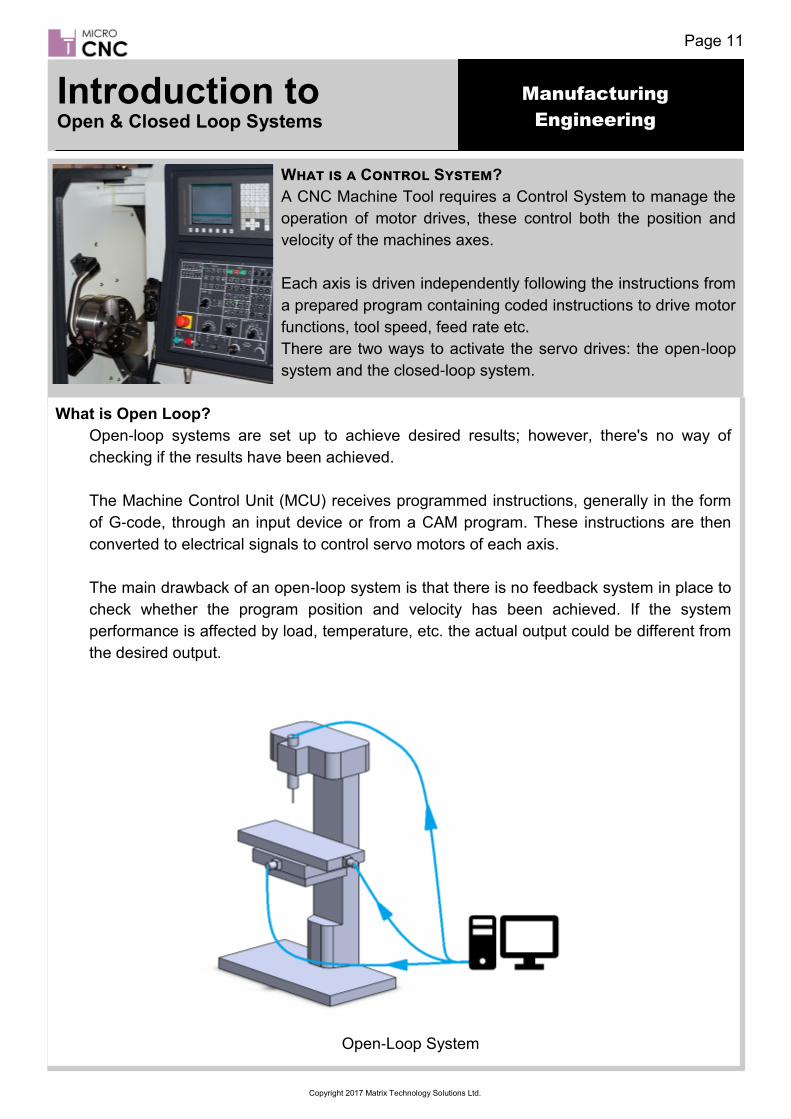
Introduction to Open & Closed Loop Systems
What is a Control System?
A CNC Machine Tool requires a Control System to manage the
operation of motor drives, these control both the position and
velocity of the machines axes.
Each axis is driven independently following the instructions from
a prepared program containing coded instructions to drive motor
functions, tool speed, feed rate etc.
There are two ways to activate the servo drives: the open-loop
system and the closed-loop system.
What is Open Loop?
Open-loop systems are set up to achieve desired results; however, there's no way of
checking if the results have been achieved.
The Machine Control Unit (MCU) receives programmed instructions, generally in the form
of G-code, through an input device or from a CAM program. These instructions are then
converted to electrical signals to control servo motors of each axis.
The main drawback of an open-loop system is that there is no feedback system in place to
check whether the program position and velocity has been achieved. If the system
performance is affected by load, temperature, etc. the actual output could be different from
the desired output.
Open-Loop System

Manufacturing
Engineering
Page 12
Copyright 2017 Matrix Technology Solutions Ltd.
Open & Closed Loop Systems
What is a Control System?
A CNC Machine Tool requires a Control System to manage the
operation of motor drives, these control both the position and
velocity of the machines axes.
Each axis is driven independently following the instructions from
a prepared program containing coded instructions to drive motor
functions, tool speed, feed rate etc.
There are two ways to activate the servo drives: the open-loop
system and the closed-loop system.
What is Closed Loop?
Closed-loop systems are able to correct errors in position and velocity in order to meet
target results. This is achieved through feedback from sensors.
Again the MCU receives programmed instructions that are converted to electrical signals to
control servo motors of each axis as with an open loop system. However, with a closed
loop system the MCU receives additional information from either Analogue or Digital
sensors connected to each axis. These sensors monitor the position and velocity at the
output and adjust the process accordingly.
Closed-loop systems are very powerful and accurate because they are capable of
monitoring operating conditions through feedback subsystems and automatically
compensating for any variations in real-time. Most modern closed-loop CNC systems are
able to provide very close resolution of 0.00254mm.
Closed-Loop System

Manufacturing
Engineering
Page 13
Copyright 2017 Matrix Technology Solutions Ltd.
Open & Closed Loop Systems
Activity Investigate how feedback is achieved through the use of linear encoders and resolvers.

Manufacturing
Engineering
Page 14
Copyright 2017 Matrix Technology Solutions Ltd.
Introduction to Part Programming & Program Efficiency
What is part programming? Machining a component involves the relative movement between a cutting tool and a workpiece. In machine tools this is accomplished by either moving the tool with respect to workpiece or vice versa. In order to define relative motion of two objects, reference directions are required to be defined. These reference directions depend on the type of machine tool and are defined by considering an imaginary coordinate system on the machine tool. A program defining motion of tool / workpiece in this coordinate system is known as a part program.
Part Programming
In general terms there are three methods of Part Programming, Manual, Conversational,
and Computer Aided Manufacturing (CAM); each method has advantages and
disadvantages depending on the type, and complexity, of the part being made, and the type
of tooling to be used to manufacture a part.
Manual programming is usually employed when the parts to be produced are simple, or when
new programs are not required very often. Manual programming is also sometimes used
where there is a need for the CNC program to execute as efficiently as possible. In Manual
Programming the programmer will write the program in the same language that the CNC
machine will use.
Advantages
• Can be very efficient if/when correctly formatted.
Disadvantages
• Can be error prone
• Can be tedious to write programmes
Conversational programming is usually employed in busy machine shops when programs
must be written while the tooling machine is in use, being set up, or during down time for
repair etc. Conversational programming is beneficial where companies have lots of repeat
business, small production runs, or production runs have very short cycle times.
Advantages
• Can quickly create a CNC program.
• Programs can be entered without any mathematical knowledge.
• Removes the tediousness of manual programming.
Disadvantages
• Cannot be programmed while the machine is in use.

Manufacturing
Engineering
Page 15
Copyright 2017 Matrix Technology Solutions Ltd.
Part Programming & Programming Efficiency
CAM programming methods are usually employed when there are a variety of machines to
program, there is lots of new business (many programs to create), and/or jobs are quite
complex (making it difficult to manually program).
Advantages
• CNC program is generated automatically.
• Programs are generally more efficient than conversational programmes.
• Removes the tediousness of manual programming.
Disadvantages
• CAM systems are costly (Not as much today as a few years ago)

Manufacturing
Engineering
Page 16
Copyright 2017 Matrix Technology Solutions Ltd.
Introduction to CNC Processes for Turning & Milling
CNC milling and turning machines are found in precision engineering shops across the country and are used to manufacture all kinds of components. However, a range of CNC machines are required to produce the different geometries and features required e.g. cylinders, flat surfaces, rebates, bores, and tapped holes, etc.
To ensure parts are produced in the most efficient way possible it is important to understand the limits and capabilities of the different types of CNC machine. This worksheet looks at the difference between two of the major processes; CNC Turning and CNC Milling.
CNC Turning
CNC Turning uses a cutting tool that is
single-pointed, and that is inserted
parallel to the material that is to be cut.
The workpiece is rotated at varying
speeds, the cutting tool being able to
traverse the two axes of motion (X and
Y) to produce cuts that are off exact
diameters and depths.
CNC turning is used for creating
cylindrical shapes such as those that
you find in drive shafts or bolts. A CNC
turning machine can create a perfect
circular outer edge to a workpiece.
CNC turning can also be used on the inside edges of the material where it is used to
create a circular, or tubular, cavity.
CNC Milling CNC Milling uses a multi-pointed cutting tool that is rotated, and moved along the workpiece, at varying speeds; the workpiece is moved along the X and Y axes, while the cutting head is moved in the Z-axis. Milling machines are therefore used to create flat components, or components with complex shape geometries. CNC milling is used to create complicated shapes of irregular, or non-symmetrical dimensions such as engine blocks. A CNC milling machine can create perfectly flat faces, grooves, holes, recesses, and tapered features. They can work on both external and internal faces of a component, the only limitation being the positioning and access of the cutting tool to the required face to be machined.

Manufacturing
Engineering
Page 17
Copyright 2017 Matrix Technology Solutions Ltd.
Machine Turning
Turning is the process of generating machined components by progressively removing
small amounts of material from a rotating workpiece by moving a single point cutting tool
linearly along the length of the workpiece. Usually ‘Turning’ refers to the machining the
external surface of the workpiece; whereas ‘Boring’ applies to machining of internal
surfaces, and ‘Facing’ refers to cutting the end surface of the material i.e. a surface
perpendicular to the rotating axis.
Cutting tools used for turning
Roughing tools are used to quickly remove material and get the stock to ‘rough’
dimensions before finishing to the exact size with a finishing tool.
Roughing and finishing tools can be right handed, left handed, or round nosed. A right
hand tool will cut from right to left i.e. towards the headstock, a left hand tool will cut from
left to right i.e. towards the tail stock, while a round nosed tool will cut in both directions.
Other ‘Specialist’ tools, such as forming, thread cutting, and boring tools are also available
to perform specific cutting operations.
CNC Processes for Turning & Milling

Manufacturing
Engineering
Page 18
Copyright 2017 Matrix Technology Solutions Ltd.
Types of Cutting Tool
Cutting tools come in three main types
• Forged – made from a single piece of steel; supplied as blanks, these cutting tools are
ground to shape and sharpened prior to use. Typically used on ‘soft’ non-ferrous
metals.
• Carbide tipped – made from a cast steel shaft with a carbide steel tip
• Replaceable tip
Typical ‘Turning’ operations performed on a lathe
CNC Processes for Turning & Milling

Manufacturing
Engineering
Page 19
Copyright 2017 Matrix Technology Solutions Ltd.
Activity
Use the resources available to you to briefly describe the action of the cutting tool
movement in relation to the following operations
• Facing
• Taper Turning
• Contour Turning
• Chamfering
• Parting
• Boring
• Briefly describe the construction and use of a form cutting tool, a thread cutting tool,
and a knurling tool.
CNC Processes for Turning & Milling

Manufacturing
Engineering
Page 20
Copyright 2017 Matrix Technology Solutions Ltd.
Machine Milling
Milling is a process of generating machined components by progressively removing small
amounts of material, or stock, from a workpiece. The workpiece is moved at a relatively
slow rate, or feed, along the X and Y axes while the milling cutter rotating at a
comparatively high speed is moved along the Z-Axis.
The characteristic feature of the milling process is that each milling cutter tooth removes a
small amount of material in the form of small individual chips.
Types of Milling Cutters
The three basic milling
operations are shown
opposite: (A) slab milling,
(B) face milling and
(C) end milling.
In slab milling the axis of cutting tool rotates parallel to the surface of the stock material
being machined. The cutting tool has a number of teeth around its circumference, these
can be straight or helical cutting at an orthogonal or oblique angle respectively.
In face milling and end milling, the cutting tools are mounted in a spindle with an axis of
rotation vertical in relation to the surface of the stock material being machined. In face
milling the milled surface results from the action of cutting teeth located on the edge and
face of the cutting tool; whereas, in end milling the cutting teeth are located on both the
end face of the cutter and the periphery of the cutting tool, in addition, the cutting tool can
also be tilted to machine tapered surfaces.
There are many different operations that come under the term 'end milling'. For each
different operation there is a different MRR (Material Removal Rate) that increases with
the engagement section of the cutter on the workpiece.
CNC Processes for Turning & Milling

Manufacturing
Engineering
Page 21
Copyright 2017 Matrix Technology Solutions Ltd.
Introduction to Parameters
What are Tooling Parameters?
Machining involve the relatively simple process of removing material from a piece of stock material in order to create a desired part. Removal of material is achieved through the relative movement of the work piece and tool, either by rotating the workpiece (as in a lathe) or by rotating the tool (as in a milling machine); the tools used can be single point, multiple point, or abrasive tools. Within this simple process lie numerous parameters that effect many aspects of the machining process such as the time taken to complete a job, the quality and accuracy of the finish, the life of the tool, the cost of production, etc.
These are collectively known as Tooling Parameters.
Many of the parameters involved in these processes are interrelated and changing one
value can have a huge effect on another parameter. The following list gives a brief
description of the most common machine setup and tooling parameters required.
1. Idle speed:- Generally this is the speed of the cutting tool when the machine is not
cutting but is still in a running state.
2. Processing speed:- This is the effective speed during specific machining operations.
3. Default Speed:- The default running speed of the machine unless operating under any
specific processing speed.
Material machinability:- This is how easy or difficult it is to cut. The material’s hardness
is the main factor here; typically a soft material is easier to cut than a harder material,
however, other properties of a material such as ductility, strength, and toughness also
have an influence.
Cutting Tool Material:- In metal-cutting, High Speed steel and Carbide are two major
tool materials widely used with ceramic tools and Cubic Boron Nitride (CBN) being
used for machining very tough and hard materials. The material used determines the
tool’s hardness, strength, wear resistance, etc. these parameters determine how fast
the tool can cut efficiently on a job.
Cutting speed:- Cutting speed is the relative speed at which the tool cuts through the
stock material. It is normally expressed in meters per minute and higher cutting
speeds generally allow for high rates of production. For every type of material tool
there is an ideal cutting speed; these are usually supplied by the tool manufacturers in
the form of guidelines.

Manufacturing
Engineering
Page 22
Copyright 2017 Matrix Technology Solutions Ltd.
7 Spindle Speed:- Spindle speed is expressed in RPM (revolutions per minute). It is
derived from the cutting speed and the work diameter cut for turning on a lathe, or the
cutting speed and tool diameter for milling, drilling, etc. If V is the cutting speed and D
is the diameter of cutting, then Spindle speed N = V /(Pi x D)
8 Depth of cut:- This indicates how much a cutting tool digs into the stock material (in
mm) to remove material in the current pass.
9 Feed Rate:- The relative speed at which the tool is linearly traversed over the
workpiece to remove the material. In case of rotating tools with multiple cutting teeth,
such as mill cutting tool, the first parameter used is the feed rate calculated in terms of
“feed per tooth," expressed in millimetres (mm/tooth). The second parameter used is
then the “feed per revolution" (mm/rev). This is effectively feed per tooth multiplied by
the number of teeth in the cutter. For lathe operations, the feed rate is effectively the
feed per revolution that states how much a tool advances in one revolution of
workpiece.
10 Tool Geometry:- Different cutting angles, such as rake angle, clearance angles, relief
angle, approach angle, etc. determine how effectively the cutting tool digs into the
component to remove material. These parameters effect the cutting speed and feed
rate of tools.
11 Coolant:- This is used to take away the heat produced in metal-cutting, it also acts as a
lubricant in cutting hard materials to reduce tool wear. Coolants can range from cutting
oils, water-soluble oils, oil-water spray, etc. and again effect cutting speeds and feed
rate.
12 Machine/ Spindle Power:- Adequate power should be available to drive the spindle
and axes’ motors to enable the cutting tool to efficiently remove the material. The
power required for cutting is based on the material removal rate and is generally
expressed in cubic centimetres per minute, which depends on work material, tool
material, the cutting speed, depth of cut, and feed rate.
Parameters

Manufacturing
Engineering
Page 23
Copyright 2017 Matrix Technology Solutions Ltd.
Introduction to Development of a CNC Part Program
Writing a Part Program—What’s Involved?
In previous worksheets part programs were discussed as the method of defining motion of the cutting tool and the work piece in order to machine a component from a piece of stock.
This work sheet will provide an overview of the processes involved in
writing a part program
Reference Point & Coordinates
• Machine Origin
The machine origin is a fixed position set by manufacturer; on some machines this can be changed but generally it cannot be changed. Movement of the cutting tool is measured from this position. The controller always remembers cutting tool distance from the machine origin.
• Program Origin
Generally referred to as home position. The program origin is the point from where the cutting tool motion starts when executing a program; the cutting tool returns to this position at the end of the cycle. This can be any point within the workspace of the cutting tool with the exception of the space occupied by the workpiece. For CNC lathes this is generally the position where tool change is carried out.
• Part Origin
The part origin can be set at any point within the workspace of the cutting tool and needs to be defined for each new setup. The part origin is the point at which material cutting begins, this is generally along one edge of the stock material, the part to be machined existing within this space. Establishing the part origin is also referred to as setting the datum, zero shift, work shift, or floating zero.
Lathe Origin Points (2-Axes) Milling Machine Origin Points (3-Axes)

Manufacturing
Engineering
Page 24
Copyright 2017 Matrix Technology Solutions Ltd.
Axis Designation
A workpiece being machined potentially has six degrees of freedom with respect to a
Cartesian coordinate system. Three of them are liner movements (X, Y, Z) and other three
are rotary (A, B, C). Machining of simple part does not require all degrees of freedom.
However, not all machining operations require all six.
Vertical Machine Coordinates Horizontal Machine Coordinates
Lathe Axis Designation
A lathe has two degrees of freedom (X, Y). The cutting tool moves along these axes while
the workpiece is rotated. As the work piece is being rotated moving the cutting tool along
either axis would result in symmetrical cuts being made to the workpiece.
Development of a CNC Part Program
X
Z

Manufacturing
Engineering
Page 25
Copyright 2017 Matrix Technology Solutions Ltd.
Milling Machine Axis Designation
Milling machines can have between three and six degrees of freedom; however, with an
increasing number of degrees of freedom the complexity of hardware and programming
increases.
A 3-axis vertical milling machine has three degrees of freedom (X, Y, Z) as shown below.
Note that the Z-axis moves vertically in relation to the workpiece; for a horizontal milling
machine the Y-axis & Z-axis are reversed, this is to ensure the cutting tool is always
operating along the Z-axis.
A 4-axis vertical milling machine has four degrees of freedom (X, Y, Z, A) as shown below.
In this case the fourth degree of freedom ‘A’ allows the workpiece to be rotated about the X-
axis allowing all faces to be machined.
3-Axis Vertical Milling Machine 4-Axis Vertical Milling Machine
Development of a CNC Part Program
X
Y
Z
X
Y
Z
A

Manufacturing
Engineering
Page 26
Copyright 2017 Matrix Technology Solutions Ltd.
Introduction to CAD Software
What is CAD Software?
Computer Aided Design (CAD) Software programs such as
Solidworks, AutoDesk Inventor, etc. are sophisticated drawing
packages used by designers, engineers, and architects to
produce detailed precision drawings, technical illustrations, and
models.
CAD software can be used to create two-dimensional (2D)
drawings or three-dimensional (3D) models.
Once a design has been finalised in a CAD package the
drawings or models can be used with CAM Software to generate
G-Code and control CNC Machines.
Some of the advantages of CAD Software include: • Ability to produce very accurate 2D drawing or 3D model designs • Easy conversion and manipulation of drawings and models • 3D model components can be combined to create complex assemblies • Automated generation of parts lists or bill of materials (BOM)
There are many different CAD software packages available but most have a similar
working environment. This usually consists of a workspace where you will create your
drawings and models. Workspaces will consist of a number of toolbars and menus for
selecting different drawing tools, shapes, textures, views, etc. Your first steps in CAD will
be to familiarise yourself with the working environment of the CAD software package you
will be using.
Activity - Familiarise yourself with a CAD Environment.
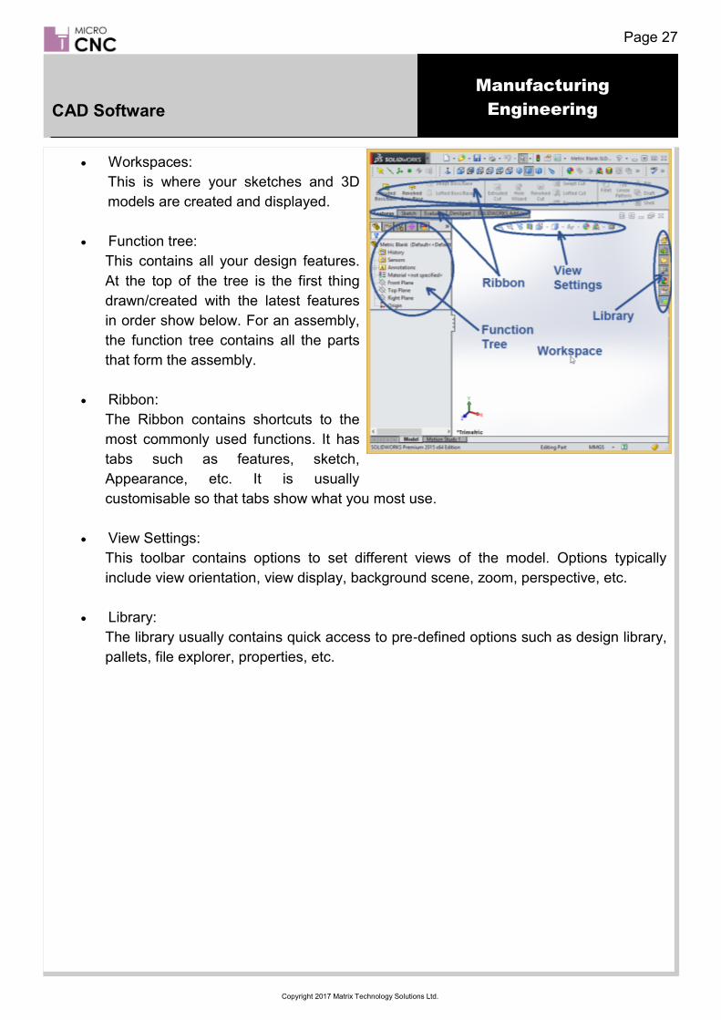
The image opposite shows a typical CAD
environment, in this case Solidworks.
All CAD packages will have similar
features although they may have different
names, and the tool bars etc. may be in
different locations.
These features typically include standard
and customisable tool ribbons (seen at the
top of the window); these include standard
commands such as ‘File Save’, ‘Open’, etc.
Other features will be:
• Workspaces: This is where your
sketches and 3D model are created
and displayed.
Manufacturing
Engineering
Page 27
Copyright 2017 Matrix Technology Solutions Ltd.
CAD Software
• Workspaces:
This is where your sketches and 3D
models are created and displayed.
• Function tree:
This contains all your design features.
At the top of the tree is the first thing
drawn/created with the latest features
in order show below. For an assembly,
the function tree contains all the parts
that form the assembly.
• Ribbon:
The Ribbon contains shortcuts to the
most commonly used functions. It has
tabs such as features, sketch,
Appearance, etc. It is usually
customisable so that tabs show what you most use.
• View Settings:
This toolbar contains options to set different views of the model. Options typically
include view orientation, view display, background scene, zoom, perspective, etc.
• Library:
The library usually contains quick access to pre-defined options such as design library,
pallets, file explorer, properties, etc.

Manufacturing
Engineering
Page 28
Copyright 2017 Matrix Technology Solutions Ltd.
Example Design a part in CAD Software
Sample Part - CAD Design Example
In this walkthrough example you will be shown the procedure for designing a sample part using a typical CAD package (Solidworks for this example); it should be possible to follow this example using what ever CAD package you have available.
This design will be used later in a CAM software example.
This example shows how to create a 3D model design that can be used with typical CAM packages to create real parts. A brief introduction to the steps involved in designing a part will be given and you will be introduced to some typical CAD operations.
It is important that you are familiar with the working environment of the CAD package to be used; this example only outlines the steps involved and does not show how to setup a workspace, or access menus, functions, etc. Start by opening your CAD package and begin a new sketch. In this example the design is started by sketching a rectangle from the origin of the Z-plane. The plane chosen is not important for this design as the part will be symmetrical around its central axis. For other designs it may be necessary to choose a specific axis, relating to the machine tools orientation, in order to be able to manufacture the part correctly or produce all the features of the design. After we have produced a sketch of the part’s outline this is ‘Extruded’ to form a 3D model. It is important to understand how 3D models relate to the sketches from which they are produced. If a feature is designed correctly, parameters such as length, angle, etc. can be easily modified and the 3D model updated. However, if it is not correctly defined when changes are made to a sketch, it will not be possible to rebuild the model. In this example the 2D sketch has been extruded to a depth of 25mm; this will produce a solid 3D model with dimensions of 50 x 25 x 25 mm to match stock material size.

Manufacturing
Engineering
Page 29
Copyright 2017 Matrix Technology Solutions Ltd.
Example Design a part in CAD Software
The next step is to create another sketch on the end face of the 3D model. This sketch will be used to create a new feature of the part.
On the right hand end face sketch a 5 x 5 mm square at the origin of the part.
Later in the design if we want to change the size of the feature we can return to the sketch and alter the dimensions; these will then be reflected in the subsequent design elements of our part.
After completing the sketch we need to add an ‘Extrude Cut’ feature. This is effectively the reverse of an Extrusion; instead of adding ’Material’ a cut will remove material from our 3D model.
Extruded cuts can be made to go through the whole part or some defined section of the model.
In this example we only want to cut away a section of the part. Make an extruded cut by selecting the sketch from the previous step and then cut into the material to a depth of 40mm.
After completing the operation your part should look like this.

Manufacturing
Engineering
Page 30
Copyright 2017 Matrix Technology Solutions Ltd.
Example Design a part in CAD Software
The next step is to use the feature from the previous step to create a pattern around our model. A pattern is simply the duplication of the feature; these can be linear or circular depending on how you need to duplicate the feature.
For this design we are going to create a linear feature in two directions so select the extruded cut feature from the previous step and then select the ‘Linear Pattern’ feature option.
For this example the extruded cut feature will be duplicated 3 times along the Y and Z Axes with a spacing of 10mm between the centres of each feature .
After completing the linear pattern feature the model should look like the image to the right.
Since we used the linear pattern feature tool and chose to
replicate the extruded cut feature 3 times in two directions we now have nine instances of the extruded cut feature.
For this design we do not want to include the square hole in the centre of the model in the machining process so we need to remove that feature from our model.

Manufacturing
Engineering
Page 31
Copyright 2017 Matrix Technology Solutions Ltd.
Example Design a part in CAD Software
To remove the central hole we create a new sketch on the model. Note that you can create the sketch on the end face of the model or on the face of the extruded cut feature. If we choose the end face of the block we would need to extrude into the material to fill the hole. If we choose the face of the extruded cut we would then extrude out of the material.
For this design we are going to create a new sketch on the face of the extruded cut.
For this example the sketch is extruded out of the material from the inner face of the cut, this will fill the hole from the inside to the outer edge of the block.
Create an extrusion of 40mm from the previous sketch.
The 3D model should now look like the image to the right. This part is now complete and is ready to be exported to a CAM package. However, most CAM packages require models to be in a specific file format.
To ensure this design can be imported into a CAM package we will save the file as a .STL file type.

Manufacturing
Engineering
Page 32
Copyright 2017 Matrix Technology Solutions Ltd.
Introduction to CAM Software
Computer Aided Manufacturing (CAM) software is
used to control machine tools for the purpose of
manufacturing components.
CAM software is generally used following the CAD
process, where a 2D or 3D design is converted into
detailed instructions (G-code) that drive computer
numerical control (CNC) machine tools; although
designs can also be produced in some CAM
software as well.
Once a component design has been finalised the part needs to be manufactured.
Generally the procedure for creating the part would be along the lines of the following
method:
Create a solid 3D model of the part to be produced. Any standard CAD format is
acceptable.
Import the solid model into the Computer Aided Manufacturing (CAM) software.
Input the raw material stock size and set the part’s coordinate origin.
Input the necessary information for each tool used in machining the part features.
Typically, a tool library will exist, which is simply a database of tools and their related
parameters.
For each part feature, select the appropriate tool from the library and set the
parameters necessary for machining that feature. Typical parameters include spindle
speed, depth of cut, feed rate, number of passes, tool path pattern, etc.
Verify the programmed tool paths by running the CAM software’s virtual machining
cycle.
Component is designed in CAD software (e.g. Solidworks) and imported into CAM software.
Within the CAM software the size of the raw material is set up and the coordinates are zeroed.
Cutting tools are selected and their tooling parameters setup and stored.

Manufacturing
Engineering
Page 33
Copyright 2017 Matrix Technology Solutions Ltd.
Typical tooling parameters include
spindle speed, depth of cut, feed
rate, number of passes, tool path
pattern, etc.
A cutting simulation is then run in the CAM software to catch any
errors before cutting.
CAM Software

Manufacturing
Engineering
Page 34
Copyright 2017 Matrix Technology Solutions Ltd.
Example Making a Part with Micro CNC Machines
4-Axis Milling Example
In this walkthrough example you will be shown the procedure for making a small component using the Micro CNC 4 axis Milling Machine.
In this example the part to be made is the Sample Part designed in the CAD example, as shown in the image to the left.
This example is using DeskProto, a 3D CAM software package.
This example shows how to import a CAD design into a typical CAM software environment; while the procedures for different software packages will be similar, there will be differences in the menus and options available.
Once the design has been imported, DeskProto will be used to create tool paths and then translate these into G-code ready to be converted by the MicroCNC control system into physical movement of the cutting tool.
First Launch of DeskProto The first time you open DeskProto you will be prompted to set up the unit dimensions. You can also change the dimension settings through the options menu in the main program. After changing/selecting ‘mm’ Click ‘OK’ to continue.
Welcome Screen Options Menu Start Screen
On the start Screen select ‘Start Wizard’.
Which Wizard Screen The first step is to set the type of operation required to create the part. For this example we need to set the software to ‘Two or more sides, automatic rotation. Once selected click the blue arrow to proceed to the next setup screen.

Manufacturing
Engineering
Page 35
Copyright 2017 Matrix Technology Solutions Ltd.
What to Machine Screen
This screen is used to select the required CAD file.
Use the browse button to open a file dialogue and select
the .STL file for the part to be machined.
Set the scaling factor to 1 - Uniform.
Select the orientation to indicate which is the top face i.e. the
face to be machined.
For this example the ‘Number of sides’ value needs to be
changed to 4
Click the blue arrow to proceed to the next setup screen.
Material and Supports Screen
This screen is used to provide the details of the stock, supports (if required), zero (origin) point and mill depth.
When a CAD file is imported into DeskProto a bounding box is applied to the imported model. This represents the smallest space in which the part can be enclosed. This is essentially the smallest size of stock that the part could be produced from.
In many instances the stock material will be larger than the finished part so we will also need to add a zero point as a starting reference.
Select ‘Bounding box of geometry’. For this part we do not need any supporting bridges so select ‘Don’t add support bridges’. Set the zero origin to be the base of the part and set the milling depth to 12.50mm (for this example).
Click the blue arrow to proceed to the next setup screen.
Roughing Screen
Roughing is the first stage in removal of material from a piece of stack. It is generally a fast cutting pass that is slightly larger than the completed part will be.
This screen is used to select the type and size of the cutter to be used, the distance between the tool paths and the cutting speed.
Most CAM software will also allow users to select the cutting strategy and other parameters . You will also need to enter the type and length of the cutter.
Select ‘Use roughing operation’, set the cutter to the type you are using; for this example we want the cutting strategy to be ‘Waterlines’
Click the blue arrow to proceed to the next setup screen.
Making a Part with Micro CNC Machines

Manufacturing
Engineering
Page 36
Copyright 2017 Matrix Technology Solutions Ltd.
Finishing Screen
The finishing operation is the final pass and the one where the part will be ‘Finished’ to the correct dimensions. This will be a fine, slow pass of the cutting tool using small steps. Select the type of cutting tool you are using, if the type of cutting tool is not in the drop down options select ‘Cutter Library’ and enter the details of your cutter. Again select the ’Waterlines’ as the cutting strategy. Click the blue arrow to proceed to the next setup screen.
Send to Machine Screen
The final screen is a confirmation screen and provides an overview of the cutting program the wizard has created.
If you are happy with the cutting program select ‘Calculate’ to calculate the cutting tool paths. However for this example we need to set some more parameters.
If the cutting program is acceptable it could be sent directly to a CNC machine if one is connected to the PC, otherwise it can be saved as an NC-program.
Select ‘Calculate’ to generate a cutting program.
Click the Green checker flag button to exit the setup wizard.
Additional Parameters
For this example we need to change the settings for the borders around the part. As we are machining a block of material there are no outside borders. From the ‘Project Tree’ double click on ‘Side #1’ ‘Roughing’ to open the Operational Parameters window. Select the ‘Borders’ tab and select ‘No Extra’ apply and exit. Repeat the above for ’finishing’ and for the other sides.
Making a Part with Micro CNC Machines

Manufacturing
Engineering
Page 37
Copyright 2017 Matrix Technology Solutions Ltd.
Simulation Before saving the G-Code it is pos-sible to view a simulation of the cut-ting tool paths. This can be done as a check to en-sure the cutting operation is as ex-pected. After creating the simulation the tool paths are shown around the part as shown opposite. Run a simulation for each side to ensure the correct parame-ters have been set.
Saving the GCode File
After checking all the cutting parameters are correct the cutting program needs to be saved as G-code. This is done by saving the file as a .ngc Note: The file name needs to be 8 characters or less
Making a Part with Micro CNC Machines

Manufacturing
Engineering
Page 38
Copyright 2017 Matrix Technology Solutions Ltd.
The G-code file can be for the entire operation or for a single operation chain. This depends on whether you need to change the tool to move between operations.
A warning will let you know if you are saving multiple operations as a single G-code file.
After exiting the setup wizard the CAD model is shown with the programmed toolpaths displayed.
Making a Part with Micro CNC Machines

Manufacturing
Engineering
Page 39
Copyright 2017 Matrix Technology Solutions Ltd.
Copying files to the CNC machine
Once DeskProto has been used to generate the G-Code the saved .NGC file needs to be copied to the Micro CNC Controller as follows:
Connect USB cable from PC to Micro CNC Controller.
A new drive will appear on your local computer folder.
Browse to the following directory.
MatrixCNC /
Double click the file Launch_File_Transfer.bat
Click Login
If you get a Warning message click ‘Add’ and then login again.
Making a Part with Micro CNC Machines

Manufacturing
Engineering
Page 40
Copyright 2017 Matrix Technology Solutions Ltd.
Copy your g code .ngc files to the /home/machinekit/nc_files folder.
Performing A Cutting Operation
Connect USB cable from PC to CNC Machine.
A new drive will appear on your local computer folder.
Browse to the following directory.
MatrixCNC /
Double click the file that corresponds to your machine setup.
Making a Part with Micro CNC Machines

Manufacturing
Engineering
Page 41
Copyright 2017 Matrix Technology Solutions Ltd.
Click the Open icon to open your G code file.
Click the Toggle Emergency Stop button (top left) to bring the machine online.
Click the machine power button (2nd from Left) to power up the machine ready for operations.
Making a Part with Micro CNC Machines

Manufacturing
Engineering
Page 42
Copyright 2017 Matrix Technology Solutions Ltd.
Select your axis, (X, Y, Z, A) and use the + / - buttons to move the axis.
Select each axis in turn and click the Home Axis button to confirm the axis has been initialised in the start 0,0,0,0 position.
An icon will appear next to the axis that have been homed, shown are X and Y.
Once all axes are homed start the operation by clicking the Play button.
The screen will animate and show the current position of the end cutter as well as the G code.
Making a Part with Micro CNC Machines

Manufacturing
Engineering
Page 43
Copyright 2017 Matrix Technology Solutions Ltd.
Lathe Task 1 This task involves producing a simple part using the MicroCNC Lathe. You should use the following 2D Drawing and 3D model to:
1. Produce the part manually - this will involve marking out the stock material and manually operating the X, and Y-axes independently.
2. Manually write G-code to your CAM software.
3. Re-create the drawing and model using your CAD package and export this to your CAM system.
;Worksheet1 - Lathe - Manual Written G-Code ;Assuming 0,0 Origin at end (Tailstock) of 28mm diameter stock, 14mm from central pivot ;Absolute Coordinates G21 ;mm Units G90 ;Absolute Coordinates G1 X-2 F2 ;Move X axis down 2mm into material speed 2mm/s G1 Z-60 F2 ;Move along stock piece cutting 12mm radius G1 Z0 F10 ;Move back to Z0 G1 X-6 F2 ;Move X axis down another 4mm into material G1 Z-35 F2 ;Move along stock piece cutting 8mm radius G1 Z0 F10 ;Move back to Z0 G1 X-10 F2 ;Move X axis down another 4mm into material G1 Z-15 F2 ;Move along stock piece cutting 4mm radius G1 X0 F10 ;Move X axis back to start position G1 Z0 F10 ;Move Z axis back to start position
Worksheet 1 Lathe - Stepped Cylindrical Part

Manufacturing
Engineering
Page 44
Copyright 2017 Matrix Technology Solutions Ltd.
Lathe Task 2 This task involves producing a relatively simple part using the MicroCNC Lathe. You should use the following 2D Drawing and 3D model to:
1. Produce the part manually - this will involve marking out the stock material and manually operating the X, and Y-axes both independently and simultaneously .
2. Manually write G-code to your CAM software.
3. Re-create the drawing and model using your CAD package and export this to your CAM system.
;Worksheet2 - Lathe - Manual Written G-Code ;Assuming 0,0 Origin at end (Tailstock) of 28mm diameter stock, 14mm from central pivot ;Absolute Coordinates G21 ;mm Units G90 ;Absolute Coordinates G1 X-8 F2 ;Move X axis 8mm into stock, at speed 2mm/s (6mm radius) G1 Z-13 X-2 F2 ;Move X axis diagonally out of the stock (6mm to 12mm radius) G1 Z-23 F2 ;Move along stock cutting 12mm radius G1 Z-26.5 X-5.5 F2 ;Move X axis diagonally into stock 3.5mm (8.5mm radius) G1 Z-41.5 F2 ;Move along stock cutting 8.5mm radius G1 Z-45 X-2 F2 ;Move X axis diagonally out of stock 3.5mm (12mm radius) G1 Z-60 F2 ;Move along stock cutting 12mm radius G1 X0 F10 ;Move X axis back to start position G1 Z0 F10 ;Move Z axis back to start position
Worksheet 2 Lathe - Tapered Cylindrical Part

Manufacturing
Engineering
Page 45
Copyright 2017 Matrix Technology Solutions Ltd.
Lathe Task 3 This task involves producing a part with complex geometry using the MicroCNC Lathe. You should use the following 2D Drawing and 3D model to:
1. Produce the part manually - this will involve marking out the stock material and manually operating the X, and Y-axes both independently and simultaneously.
2. Re-create the drawing and model using your CAD package and export this to your CAM system.
Worksheet 3 Lathe - Complex Cylindrical Part

Manufacturing
Engineering
Page 46
Copyright 2017 Matrix Technology Solutions Ltd.
3-Axis Milling Machine Task 1 This task involves producing a simple jigsaw using the MicroCNC 3-axis Milling Machine. You should use the following 2D Drawing and 3D model to:
1. Produce the part manually - this will involve marking out the stock material and manually operating the X, and Y-axes independently; you will also control the depth of the cutting tool by manually operating the Z-axis.
2. Manually write G-code to your CAM software.
3. Re-create the drawing and model using your CAD package and export this to your CAM system.
Worksheet 4 3-Axis Milling - Simple Jigsaw

Manufacturing
Engineering
Page 47
Copyright 2017 Matrix Technology Solutions Ltd.
;Worksheet4 - 3-Axis - Manual Written G-Code ;Assuming 0,0,0 start origin at bottom left corner of stock, Z should be positioned so the mill bit is as close as possible to the top of the stock but not touching ;Absolute Coordinates G21 ;mm Units G90 ;Absolute Coordinates G0 Z1 F10 ;Move Z axis up to 1mm to perform a rapid movement G0 X4 Y25 F10 ;Move to absolute 4, 25 rapid movement G1 Z-3 F2 ;Move Z axis down 3mm into material - Begin inner cut - Horizontal G1 X10.5 F2 ;Move X+ by 6.5mm G1 Y21 F2 ;Move Y- by 4mm G1 X18.5 F2 ;Move X+ by 8mm G1 Y25 F2 ;Move Y+ by 4mm G1 X31.5 F2 ;Move X+ by 13mm (2 x 6.5mm) G1 Y29 F2 ;Move Y+ by 4mm G1 X39.5 F2 ;Move X+ by 8mm G1 Y25 F2 ;Move Y- by 4mm G1 X46 F2 ;Move X+ by 6.5mm G0 Z1 F2 ;Move Z axis up to 1mm to perform a rapid movement G0 X25 Y4 F10 ;Move to absolute 25, 4 rapid movement G1 Z-3 F2 ;Move Z axis down 3mm into material - Continue inner cut - Vertical G1 Y10.5 F2 ;Move Y+ by 6.5mm G1 X29 F2 ;Move X+ by 4mm G1 Y39.5 F2 ;Move Y+ by 8mm G1 X25 F2 ;Move X- by 4mm G1 Y31.5 F2 ;Move Y+ by 13mm (2 x 6.5mm) G1 X21 F2 ;Move X- by 4mm G1 Y18.5 F2 ;Move Y+ by 8mm G1 X25 F2 ;Move X+ by 4mm G1 Y46 F2 ;Move Y+ by 6.5mm G0 Z1 F2 ;Move Z axis up to 1mm to perform a rapid movement G0 X4 Y4 F10 ;Move to absolute 4, 4 rapid movement G1 Z-3 F2 ;Move Z axis down 3mm into material - Outer perimeter cut - Double check your clamps are not in the way! G1 X46 F2 ;Move X+ by 42mm G1 Y46 F2 ;Move Y+ by 42mm G1 X4 F2 ;Move X- by 42mm G1 Y4 F2 ;Move Y- by 42mm G0 Z1 F2 ;Move Z axis up to 1mm to perform a rapid movement G0 X0 Y0 F10 ;Move to absolute 0, 0 rapid movement G0 Z0 F10 ;Move to absolute 0,0,0 rapid movement
Worksheet 4 (cont.) 3-Axis Milling - Simple Jigsaw
Manufacturing
Engineering
Page 48
Copyright 2017 Matrix Technology Solutions Ltd.
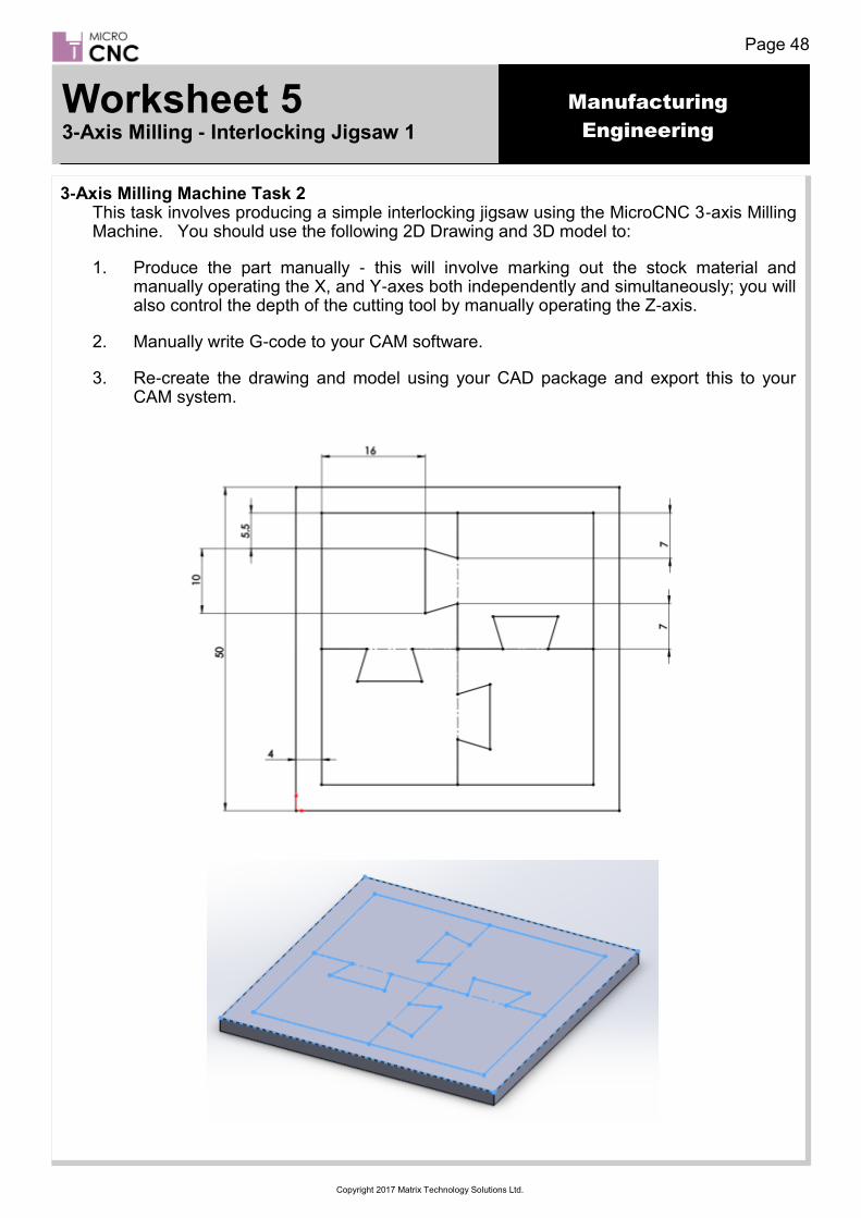
3-Axis Milling Machine Task 2 This task involves producing a simple interlocking jigsaw using the MicroCNC 3-axis Milling Machine. You should use the following 2D Drawing and 3D model to:
1. Produce the part manually - this will involve marking out the stock material and manually operating the X, and Y-axes both independently and simultaneously; you will also control the depth of the cutting tool by manually operating the Z-axis.
2. Manually write G-code to your CAM software.
3. Re-create the drawing and model using your CAD package and export this to your CAM system.
Worksheet 5 3-Axis Milling - Interlocking Jigsaw 1

Manufacturing
Engineering
Page 49
Copyright 2017 Matrix Technology Solutions Ltd.
;Worksheet5 - 3-Axis - Manual Written G-Code ;Assuming 0,0,0 start origin at bottom left corner of stock, Z should be positioned so the mill bit is as close as possible to the top of the stock but not touching ;Absolute Coordinates G21 ;mm Units G90 ;Absolute Coordinates G0 Z1 F10 ;Move Z axis up to 1mm to perform a rapid movement G0 X4 Y25 F10 ;Move to absolute 4, 25 rapid movement G1 Z-3 F2 ;Move Z axis down 3mm into material - Begin inner cut - Horizontal G1 X11 F2 ;Move X+ by 7mm G1 X9.5 Y20 F2 ;Move X- by 1.5mm Y- by 5mm G1 X19.5 F2 ;Move X+ by 10mm G1 X18 Y25 F2 ;Move X- by 1.5mm Y+ by 5mm G1 X32 F2 ;Move X+ by 14mm G1 X30.5 Y30 F2 ;Move X- by 1.5mm Y+ by 5mm G1 X40.5 F2 ;Move X+ by 10mm G1 X39 Y25 F2 ;Move X- by 1.5mm Y- by 5mm G1 X46 F2 ;Move X+ by 7mm G0 Z1 F2 ;Move Z axis up to 1mm to perform a rapid movement G0 X25 Y4 F10 ;Move to absolute 25, 4 rapid movement G1 Z-3 F2 ;Move Z axis down 3mm into material - Continue inner cut - Vertical G1 Y11 F2 ;Move Y+ by 7mm G1 X30 Y9.5 F2 ;Move X+ by 5mm Y- by 1.5mm G1 Y19.5 F2 ;Move Y+ by 10mm G1 X25 Y18 F2 ;Move X- by 5mm Y- by 1.5mm G1 Y32 F2 ;Move Y+ by 14mm G1 X20 Y30.5 F2 ;Move X- by 5mm Y- by 1.5mm G1 Y40.5 F2 ;Move Y+ by 10mm G1 X25 Y39 F2 ;Move X+ by 5mm Y- by 1.5mm G1 Y46 F2 ;Move Y+ by 7mm G0 Z1 F2 ;Move Z axis up to 1mm to perform a rapid movement G0 X4 Y4 F10 ;Move to absolute 4, 4 rapid movement G1 Z-3 F2 ;Move Z axis down 3mm into material - Outer perimeter cut - Double check your clamps are not in the way! G1 X46 F2 ;Move X+ by 42mm G1 Y46 F2 ;Move Y+ by 42mm G1 X4 F2 ;Move X- by 42mm G1 Y4 F2 ;Move Y- by 42mm G0 Z1 F2 ;Move Z axis up to 1mm to perform a rapid movement G0 X0 Y0 F10 ;Move to absolute 0, 0 rapid movement G0 Z0 F10 ;Move to absolute 0,0,0 rapid movement
Worksheet 5 (cont.) 3-Axis Milling - Interlocking Jigsaw 1

Manufacturing
Engineering
Page 50
Copyright 2017 Matrix Technology Solutions Ltd.
3-Axis Milling Machine Task 3 This task involves producing a Complex interlocking jigsaw using the MicroCNC 3-axis Milling Machine. You should use the following 2D Drawing and 3D model to:
1. Produce the part manually - this will involve marking out the stock material and manually operating the X, and Y-axes both independently and simultaneously; you will also control the depth of the cutting tool by manually operating the Z-axis.
2. Re-create the drawing and model using your CAD package and export this to your CAM system.
Worksheet 6 3-Axis Milling - Interlocking Jigsaw 2

Manufacturing
Engineering
Page 51
Copyright 2017 Matrix Technology Solutions Ltd.
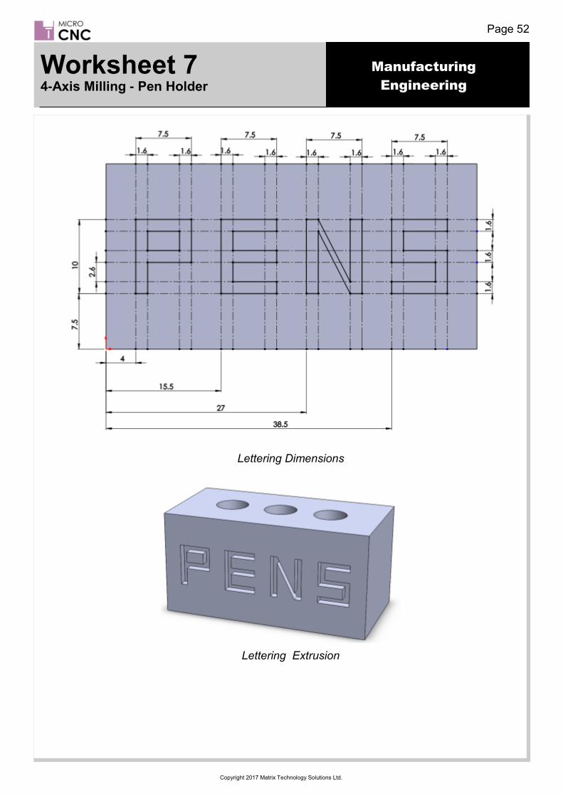
4-Axis Milling Machine Task 1 This task involves producing a small pen holder using the MicroCNC 4-axis Milling Machine. For this task you machine two faces of a 50 x 25 x 25 mm block. You should use the following 2D Drawings and 3D model to:
1. Produce the part manually - this will involve marking out the stock material and manually operating the X, and Y-axes both independently and simultaneously; you will also control the depth of the cutting tool by manually operating the Z-axis.
2. Manually write G-code to your CAM software.
3. Re-create the drawing and model using your CAD package and export this to your CAM system.
Block Dimensions
Hole Dimensions and Extrusion
Worksheet 7 4-Axis Milling - Pen Holder
Manufacturing
Engineering
Page 52
Copyright 2017 Matrix Technology Solutions Ltd.
Lettering Dimensions
Lettering Extrusion
Worksheet 7 4-Axis Milling - Pen Holder

Manufacturing
Engineering
Page 53
Copyright 2017 Matrix Technology Solutions Ltd.
;Worksheet7 - 4-Axis - Manual Written G-Code ;Assuming 0,0,0 start origin at bottom left corner of stock, Z should be positioned so the mill bit is as close as possible to the top of the stock but not touching ;Ensure 10mm of cutting mill is available ;Absolute Coordinates G21 ;mm Units G90 ;Absolute Coordinates G0 Z1 F10 ;Move Z axis up to 1mm to perform a rapid movement G0 X4 Y7.5 F10 ;Move to absolute 4, 7.5 rapid movement G1 Z-2 F2 ;Move Z axis down 2mm into material - P cut G1 Y17.5 F2 ;Move Y+ by 10mm G1 X11.5 F2 ;Move X+ by 7.5mm G1 Y12.5 F2 ;Move Y- by 5mm G1 X4 F2 ;Move X- by 7.5mm G0 Z1 F2 ;Move Z axis up to 1mm to perform a rapid movement G0 X23 Y7.5 F10 ;Move to absolute 23, 7.5 rapid movement G1 Z-2 F2 ;Move Z axis down 2mm into material - E cut G1 X15.5 F2 ;Move X- by 7.5mm G1 Y12.5 F2 ;Move Y+ by 5mm G1 X23 F2 ;Move X+ by 7.5mm G1 X15.5 F2 ;Move X- by 7.5mm G1 Y17.5 F2 ;Move Y+ by 5mm G1 X23 F2 ;Move X+ by 7.5mm G0 Z1 F2 ;Move Z axis up to 1mm to perform a rapid movement G0 X27 Y7.5 F10 ;Move to absolute 27, 7.5 rapid movement G1 Z-2 F2 ;Move Z axis down 2mm into material - N cut G1 Y17.5 F2 ;Move Y+ by 10mm G1 X34.5 Y7.5 F2 ;Move X+ by 7.5mm Y- by 10mm G1 Y17.5 F2 ;Move Y+ by 10mm G0 Z1 F2 ;Move Z axis up to 1mm to perform a rapid movement G0 X38.5 Y7.5 F10 ;Move to absolute 38.5, 7.5 rapid movement G1 Z-2 F2 ;Move Z axis down 2mm into material - S cut G1 X46 F2 ;Move X+ by 7.5mm G1 Y12.5 F2 ;Move Y+ by 5mm G1 X38.5 F2 ;Move X- by 7.5mm G1 Y17.5 F2 ;Move Y+ by 5mm G1 X46 F2 ;Move X+ by 7.5mm G0 Z1 F2 ;Move Z axis up to 1mm to perform a rapid movement G0 X55 Y0 F10 ;Move Cutting tool out of the way of rotation G0 A90 F10 ;Move A axis 90 degrees rapid movement G0 X6 Y8.5 F10 ;Move to absolute 6, 8.5 rapid movement
Worksheet 7 4-Axis Milling - Pen Holder

Manufacturing
Engineering
Page 54
Copyright 2017 Matrix Technology Solutions Ltd.
G1 Z-5 F2 ;Move Z axis down 5mm into material - Hole 1 G1 Y16.5 F2 ;Move Y+ by 8mm G1 X7 F2 ;Move X+ by 1mm G1 Y8.5 F2 ;Move Y- by 8mm G1 X8 F2 ;Move X+ by 1mm G1 Y16.5 F2 ;Move Y+ by 8mm G1 X9 F2 ;Move X+ by 1mm G1 Y8.5 F2 ;Move Y- by 8mm G1 X10 F2 ;Move X+ by 1mm G1 Y16.5 F2 ;Move Y+ by 8mm G1 X11 F2 ;Move X+ by 1mm G1 Y8.5 F2 ;Move Y- by 8mm G1 X12 F2 ;Move X+ by 1mm G1 Y16.5 F2 ;Move Y+ by 8mm G1 X13 F2 ;Move X+ by 1mm G1 Y8.5 F2 ;Move Y- by 8mm G1 X14 F2 ;Move X+ by 1mm G1 Y16.5 F2 ;Move Y+ by 8mm G1 X6 Y8.5 F10 ;Move to absolute 6, 8.5 G1 Z-10 F2 ;Move Z axis down 10mm into material - Hole 1 G1 Y16.5 F2 ;Move Y+ by 8mm G1 X7 F2 ;Move X+ by 1mm G1 Y8.5 F2 ;Move Y- by 8mm G1 X8 F2 ;Move X+ by 1mm G1 Y16.5 F2 ;Move Y+ by 8mm G1 X9 F2 ;Move X+ by 1mm G1 Y8.5 F2 ;Move Y- by 8mm G1 X10 F2 ;Move X+ by 1mm G1 Y16.5 F2 ;Move Y+ by 8mm G1 X11 F2 ;Move X+ by 1mm G1 Y8.5 F2 ;Move Y- by 8mm G1 X12 F2 ;Move X+ by 1mm G1 Y16.5 F2 ;Move Y+ by 8mm G1 X13 F2 ;Move X+ by 1mm G1 Y8.5 F2 ;Move Y- by 8mm G1 X14 F2 ;Move X+ by 1mm G1 Y16.5 F2 ;Move Y+ by 8mm G0 Z1 F2 ;Move Z axis up to 1mm to perform a rapid movement
Worksheet 7 4-Axis Milling - Pen Holder
Manufacturing
Engineering
Page 55
Copyright 2017 Matrix Technology Solutions Ltd.
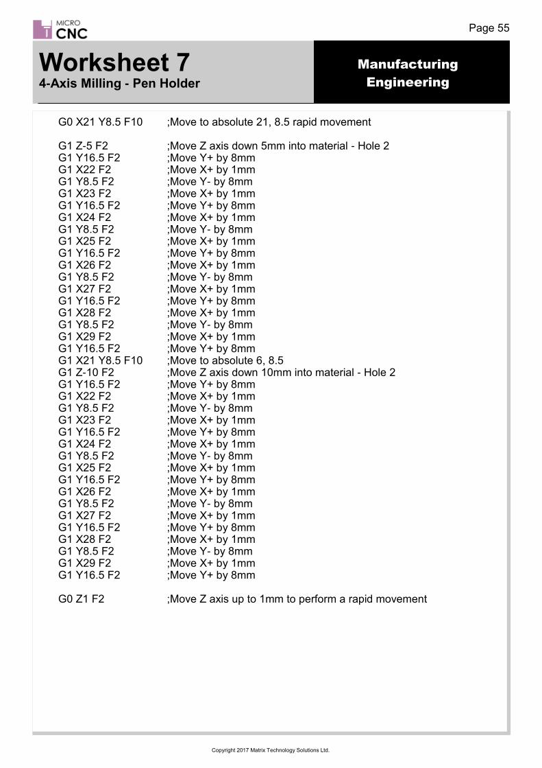
G0 X21 Y8.5 F10 ;Move to absolute 21, 8.5 rapid movement G1 Z-5 F2 ;Move Z axis down 5mm into material - Hole 2 G1 Y16.5 F2 ;Move Y+ by 8mm G1 X22 F2 ;Move X+ by 1mm G1 Y8.5 F2 ;Move Y- by 8mm G1 X23 F2 ;Move X+ by 1mm G1 Y16.5 F2 ;Move Y+ by 8mm G1 X24 F2 ;Move X+ by 1mm G1 Y8.5 F2 ;Move Y- by 8mm G1 X25 F2 ;Move X+ by 1mm G1 Y16.5 F2 ;Move Y+ by 8mm G1 X26 F2 ;Move X+ by 1mm G1 Y8.5 F2 ;Move Y- by 8mm G1 X27 F2 ;Move X+ by 1mm G1 Y16.5 F2 ;Move Y+ by 8mm G1 X28 F2 ;Move X+ by 1mm G1 Y8.5 F2 ;Move Y- by 8mm G1 X29 F2 ;Move X+ by 1mm G1 Y16.5 F2 ;Move Y+ by 8mm G1 X21 Y8.5 F10 ;Move to absolute 6, 8.5 G1 Z-10 F2 ;Move Z axis down 10mm into material - Hole 2 G1 Y16.5 F2 ;Move Y+ by 8mm G1 X22 F2 ;Move X+ by 1mm G1 Y8.5 F2 ;Move Y- by 8mm G1 X23 F2 ;Move X+ by 1mm G1 Y16.5 F2 ;Move Y+ by 8mm G1 X24 F2 ;Move X+ by 1mm G1 Y8.5 F2 ;Move Y- by 8mm G1 X25 F2 ;Move X+ by 1mm G1 Y16.5 F2 ;Move Y+ by 8mm G1 X26 F2 ;Move X+ by 1mm G1 Y8.5 F2 ;Move Y- by 8mm G1 X27 F2 ;Move X+ by 1mm G1 Y16.5 F2 ;Move Y+ by 8mm G1 X28 F2 ;Move X+ by 1mm G1 Y8.5 F2 ;Move Y- by 8mm G1 X29 F2 ;Move X+ by 1mm G1 Y16.5 F2 ;Move Y+ by 8mm G0 Z1 F2 ;Move Z axis up to 1mm to perform a rapid movement
Worksheet 7 4-Axis Milling - Pen Holder

Manufacturing
Engineering
Page 56
Copyright 2017 Matrix Technology Solutions Ltd.
G0 X36 Y8.5 F10 ;Move to absolute 36, 8.5 rapid movement G1 Z-5 F2 ;Move Z axis down 5mm into material - Hole 3 G1 Y16.5 F2 ;Move Y+ by 8mm G1 X37 F2 ;Move X+ by 1mm G1 Y8.5 F2 ;Move Y- by 8mm G1 X38 F2 ;Move X+ by 1mm G1 Y16.5 F2 ;Move Y+ by 8mm G1 X39 F2 ;Move X+ by 1mm G1 Y8.5 F2 ;Move Y- by 8mm G1 X40 F2 ;Move X+ by 1mm G1 Y16.5 F2 ;Move Y+ by 8mm G1 X41 F2 ;Move X+ by 1mm G1 Y8.5 F2 ;Move Y- by 8mm G1 X42 F2 ;Move X+ by 1mm G1 Y16.5 F2 ;Move Y+ by 8mm G1 X43 F2 ;Move X+ by 1mm G1 Y8.5 F2 ;Move Y- by 8mm G1 X44 F2 ;Move X+ by 1mm G1 Y16.5 F2 ;Move Y+ by 8mm G1 X36 Y8.5 F10 ;Move to absolute 6, 8.5 G1 Z-10 F2 ;Move Z axis down 10mm into material - Hole 3 G1 Y16.5 F2 ;Move Y+ by 8mm G1 X37 F2 ;Move X+ by 1mm G1 Y8.5 F2 ;Move Y- by 8mm G1 X38 F2 ;Move X+ by 1mm G1 Y16.5 F2 ;Move Y+ by 8mm G1 X39 F2 ;Move X+ by 1mm G1 Y8.5 F2 ;Move Y- by 8mm G1 X40 F2 ;Move X+ by 1mm G1 Y16.5 F2 ;Move Y+ by 8mm G1 X41 F2 ;Move X+ by 1mm G1 Y8.5 F2 ;Move Y- by 8mm G1 X42 F2 ;Move X+ by 1mm G1 Y16.5 F2 ;Move Y+ by 8mm G1 X43 F2 ;Move X+ by 1mm G1 Y8.5 F2 ;Move Y- by 8mm G1 X44 F2 ;Move X+ by 1mm G1 Y16.5 F2 ;Move Y+ by 8mm G0 Z1 F2 ;Move Z axis up to 1mm to perform a rapid movement G0 X0 Y0 F10 ;Move to absolute 0, 0 rapid movement G0 Z0 F10 ;Move to absolute 0,0,0 rapid movement
Worksheet 7 4-Axis Milling - Pen Holder