Embed Size (px)
Citation preview

International Research Journal of Engineering and Technology (IRJET) e-ISSN: 2395-0056
Volume: 08 Issue: 06 | June 2021 www.irjet.net p-ISSN: 2395-0072
© 2021, IRJET | Impact Factor value: 7.529 | ISO 9001:2008 Certified Journal | Page 4499
Manufacturing and Analysis of Bladeless fan with Thermoelectric
Cooler
Ratnam Gujar1, Jay Ghongade2, Arnab Bhattacharjee3, Himanshu Kandpal4, Tejas Rawate5
1Assistant Professor, Dept. of Mechanical Engineering, MCT’s Rajiv Gandhi Institute of Technology, Mumbai, Maharashtra, India.
2,3,4,5Students, Mechanical Engineering Department, MCT’s Rajiv Gandhi Institute of Technology, Mumbai, Maharashtra, India.
---------------------------------------------------------------------***---------------------------------------------------------------------
Abstract – Fans are machines that are used for producing airflow, it forces air with a very high velocity and eventually causes the sensation of cooling. However traditional fans use visible blades that do not cool the air being released at the observer and air coming out is of the same temperature. In the present study, a bladeless fan with TEC which reduces the temperature of the air is constructed and studied for a single person. The manufacturing of each component which is done using sheet metal and sheet metal processes are explained along with its assembly of all the electronic connection. To avoid physical contact and regulate the function HC-05 Bluetooth module is used using the Android application. Airflow analysis of the project is done on Ansys Fluent to determine the velocity of air at various distances. Key Words: Bladeless fan, TEC, Sheet Metal Manufacturing, HC-05 Bluetooth module, Ansys Fluent Analysis.
1.INTRODUCTION In the present study, a bladeless fan was designed with sheet metal using Autodesk Inventor and constructed by the combination of laser cutting, rolling, taper rolling, and welding. Since it is not made up of 3D printing material it is cost-effective and because of its compactness, it is portable in a domestic setting.
Fans are devices that are used for cooling purposes, but in actual fans do not cool air but it creates a stagnant fluid in the space or room to move to another part of the room and thus create a fluid (here air) circulation. The moisture or sweat present on our skin when comes into contact with air evaporates, this evaporative effect produces a sensation of cooling on the human body. Stagnant air does not produce as much evaporative effect as moving air. This is because the heat transferred from body to surrounding is directly proportional to the heat transfer coefficient. The heat transfer coefficient for stagnant fluid i.e free convection is always lesser than the heat transfer coefficient of moving air i.e forced convection.
So, to design a fan, not only the velocity of air but also the amount of air must be considered as a parameter at the outlet. In short, the amount of air must be multiplied.
A Bladeless fan sucks the air through small vents present at the bottom of the fan. Blowers or impellers or motors with blades are used to create a pressure difference and are used to extract the air inside this fan. This extracted air is then moved over the special airfoil-shaped hoop. The airfoil is so designed that air when moves over this hoop while leaving entrains more air as it moves a certain distance as a result of eddies. Now, since the surrounding air is stationary and air coming out of the circular hoop has some velocity, as a result of Bernoulli’s principle a low-pressure region is created at the inlet of the hoop. This pressure difference induces more air from behind to the front of the bladeless fan. The air coming out of the bladeless fan is as a result of sucked air, induced air, and entrained air which is more than only sucked air, thus the air is multiplied.
In this project, the TEC modules are used to cool the air which is sucked in, the cool air is then forcibly passed through the hoop and to the observer. The air is not only multiplied but also cooled before it reaches the observer.
1.1 OBJECTIVES The objectives of our work are:
To design a fan that lowers the temperature of the air.
To design a compact fan with added electronic features for domestic purposes.
To make a cost-efficient model of air multiplier.
To simulate few airfoils and decide the best-suited airfoil for the given size of the fan.
To determine the energy parameters and to test the overall energy savings in the fan concerning traditional axial fan.
The objective of the project is to make a fan that will be used in places where space is limited.
2. METHODOLOGY The overall Methodology of our project can be summarised in the form of following flow chart:

International Research Journal of Engineering and Technology (IRJET) e-ISSN: 2395-0056
Volume: 08 Issue: 06 | June 2021 www.irjet.net p-ISSN: 2395-0072
© 2021, IRJET | Impact Factor value: 7.529 | ISO 9001:2008 Certified Journal | Page 4500
3. ARRANGEMENT OF COMPONENTS
Fig -1: Centrifugal fan(green) assembly at the bottom with
the main base.
At the main base frame, two centrifugal fans are placed for proper suction of air into the fan. For suction of the air, vertical vents are provided at four sides to suck the air into the fan. The trial was taken to use only one centrifugal fan, but since the velocity of air observed was less hence two centrifugal fans are used, to suck more amount of air . The advantage of using centrifugal fans is at very little volume they suck the maximum amount of air. Axial fans require additional space at the bottom of the main base to suck the air, however, a centrifugal fan sucks the air and releases it at the right angle. The centrifugal fans are placed side by side with their suction side facing in the opposite direction.
Fig-2: Cold Chanber Box(blue) mounted on the main base
with centrifugal fan(green).
The air after suction from the bottom part then moves over the aluminium box (shown in blue) placed above it. The outlet of centrifugal fans is covered with an aluminium plate. This aluminium box act as the cold chamber of the project. Each of the four vertical sides of the aluminium box is in physical contact with the cold sides of the four Peltier modules used. Aluminium box is used as a material other than Mild steel because of its high thermal conductivity (thermal conductivity of aluminium box, k= 205W/mK). Materials with high thermal conductivity have very little resistance and obtain heat very quickly as a result heat can pass easily through them. Aluminium thermal conductivity is
Recognition of Need.
Deciding the principle of
operation of the project.
Make a rough design of the entire project with
the arrangement of each component based on
the Mechanism of synthesis.
Divide the entire geometry
into suitable parts.
Make individual parts on Autodesk Inventor based
on like sheet metal and convert the parts into a flat
sheet.
arrangement of each component based on the
Mechanism of synthesis.
Convert the flat sheet parts into .dxf files and Make G
and M codes of individual parts of sheet metal.
Give this feed of G and M code
to the Laser cutting machine.
Give the cut sheet metal parts to rolling, taper
rolling, bending, and welding.
Assemble all the electronic
components of the project.
Analyze the project on
Ansys.
Test and validate the
results.
Optimize the airfoils and find the best
shape for a given set of conditions.

International Research Journal of Engineering and Technology (IRJET) e-ISSN: 2395-0056
Volume: 08 Issue: 06 | June 2021 www.irjet.net p-ISSN: 2395-0072
© 2021, IRJET | Impact Factor value: 7.529 | ISO 9001:2008 Certified Journal | Page 4501
lesser than copper, but aluminium being cheap it is used as a cold chamber. (thermal conductivity of copper box, k=385W/mK). The heat is conducted evenly from the four vertical sides of the cold chamber box, which is removed by the cold side of the Peltier module. The air sucked by the centrifugal fan below it comes in contact with the sides of the cold chamber box and thus air leaves with lowering its temperature.
Fig-2: Main base attached with Peltier Module(Yellow)
and fins(green).
The rectangular spaces provided in the main base are used for connection Peltier modules(as shown in yellow). The Peltier modules with cold sides are connected to the aluminium box. For proper adherence of the Peltier module to the aluminium box, thermal pastes are applied. The hot side of the aluminium box is connected to the heat sinks (as shown in green), again for proper adherence thermal paste is applied. Heat sink connected dissipate away the heat liberated from the hot side to the atmosphere. The heat sink is connected externally by the axial flow heatsink fans (as shown in red) using a nut and bolt assembly.
Fig 3- Main base with axial flow fans, top view of the main base, and cover of aluminium box.
When the air is passed through the cold chamber, it is passed over the circular hoop on the top. The hoop design should involve aerodynamics to entrain, induce, and thus multiply the sucked air. The hoop design must be 3D printed and must be analyzed for various shapes for good multiplication of air.
Fig-4: Hoop of the fan, hoop with assembly.
A trial model was made of a hoop of 26cm diameter, it was given converted into STL format and the mass of the hoop was checked with ABS and PLA material, the mass of the hoop with PLA is 908g with 30% infill and mass of the hoop with ABS is 926g with 30% infill. In the 3D printing process, the objects given for printing are generally crosshatched or uses other patterns for interior surfaces and some space in the print remains empty, to completely fill the space infill percentage is increased. With 100% infill the mass of the product was 1100g for PLA and 1198g for ABS materials. The cost of ABS and PLA is Rs 16/g and Rs 9/g , the total cost Rs17,600 and Rs9,900, moreover the printing time was 42 hours. Hence FDM method of manufacturing was discarded because of cost and time of manufacturing. Hence, sheet metal cutting is used for manufacturing rather than FDM.
Fig-5: Sheet front and sectional side view of test model
made for 3D printing.
3.1 Dividing the geometry into suitable components. The Project is divided into the following parts for manufacturing it by sheet metal rolling, tapered rolling, and bending operations: 1. Hoop Outer Part 2. Hoop Back Part 3. Hoop Tapered Part 4. Main Base 5. Hoop Front Part 6. Lower Cover 7. Aluminium Box Bottom Cover 8. Aluminium Box (Cold Chamber)

International Research Journal of Engineering and Technology (IRJET) e-ISSN: 2395-0056
Volume: 08 Issue: 06 | June 2021 www.irjet.net p-ISSN: 2395-0072
© 2021, IRJET | Impact Factor value: 7.529 | ISO 9001:2008 Certified Journal | Page 4502
Fig-6: Sheet assembly of different components.
The output of the centrifugal fan was considered which is 54mm x 29mm keeping two centrifugal fans with proper assembly, the main base dimension is square with side as 120mm, the height is kept as 180mm. At the Main Base, the dimension of the Peltier modules was measured and the proper hole is drilled. For suction of air 6 vertical vents of 60mm x 4mm on each face are made by slots. Sufficient space is kept for the aluminium box. The outer diameter of the Hoop is considered 30cm. Hoop Side Part is with 120mm width and radius as 150 mm a slot is made with 54mm x 29mm for the Centrifugal fan inlet. Hoop Back Part is with 150mm outer radius and an inner radius of 135mm. Hoop outer circle is going to mate with the Hoop Side Part Hoop.The Front Part is with 150mm diameter and 105mm inner radius. Hoop Front Part is going to mate with Hoop Side Part. The lower cover is a square with a 120mm side length with a circular hole of 15 diameter. Hoop Tapered Part is of inner radius 231.21mm and outer radius as 269mm the taper angle is 100. The Hoop Tapered Part is mate with the Hoop Back Part. The flat portion of the Hoop Side Part is mate with the Main Base. Aluminium Box dimension is taken as 120mm width and 117mm height.
Fig-7: Sheet parts of different components with
dimensions.
3.2 Scaling the Standardized Airfoil. The dimensions of all other components were done by first selecting the size of the cross section of airfoil. For this purpose a stadardized airfoil is referred to avoid the problem faced due to accumulation of air inside the hoop. If the size of airfoil is too large then accumulation of mass takes place within the airfoil, which releases air with very less velocity, whereas if the size of the airfoil is less then there is more shear stress developed due to moving fluid across the thickness of airfoil. Hence appropriate length and height selection of the cross section of airfoil is necessary for
efficient release of air.
Fig-8: Dimension of Fig-9: Airfoil cross-sectional Cross Section of airfoil. with dimension. The shown airfoil is taken from “Numerical Investigation of 60cm diameter airfoil”. This airfoil is for 60cm diameter of fan, we fix our diameter of fan as 26 cm. Scaling it appropriately and increasing the length of the airfoil by 2 cm we get the length as 12 cm and height as 2cm. Length 12cm is not scaled because the dimension of the Main Base below it is 12cm which will mate with the hoop. Thus all the dimensions of the components is decided. The components are modelled based on dimension on Autodesk Inventor. The model is designed with thickness as 1mm. After modelling the individual components on Autodesk Inventor, the components are tried to assemble. After assembly the individual components are again opened and converted into sheet metal. The Hoop Tapered Part is applied with rip command and converted into flat pattern and saved. Similarly, Hooop Side Part and Main Base is converted into flat pattern and saved. Thus sheet metal components are converted into flat pattern.
3.3 Laser Cutting Parameters. Once the flat pattern parts are saved the parts are converted into .dxf file format. These are 2D files, which can be read and understood by the CNC laser cutting machine. The sheet metal used is Mild Steel with 1mm thickness. Laser beam machining is carried out in two parts i.e piercing and cutting.
Table -1: Parameters of Laser Cutting
Piercing. Cutting.
height=1.5mm height=0.6mm time=200ms speed= 10m/min [H]
Voltage= 1500V Voltage =1500V Frequency=1000Hz Frequency=5000Hz
Duty =30% Duty =100% Pressure=8bar Pressure=2.5bar

International Research Journal of Engineering and Technology (IRJET) e-ISSN: 2395-0056
Volume: 08 Issue: 06 | June 2021 www.irjet.net p-ISSN: 2395-0072
© 2021, IRJET | Impact Factor value: 7.529 | ISO 9001:2008 Certified Journal | Page 4503
Gas type: Oxygen Gas type: Oxygen Focus=2mm Focus=1mm
3.4 Rolling, Taper Rolling Bending and Welding of Sheet Metal Cut. The Sheet metal is cut based on the various shape which is input to the laser cutting machine. The cut sheet is further processed in the rolling, taper rolling and bending machine to get the shape designed in the CAD file and then finally welded to get the complete structure. Hoop Side Part is first sent for rolling to get the desired radius rolling and welded. Hoop Tapered Part is sent for tapered rolling and then welded. Main Base is sent to bending operation to bend each edge at right angles and then welded. Here uniform pressure is applied across the sheet metal to get equal radius at each end.
3.4.1Rolling. In this process there are two driving rolls and an adjustable roller. The Hoop Side Part which is cut in the laser cutting is fed to the rolling machine lengthwise. The sheet metal moves in between these rollers at speed from 0.3m/s to 1.5m/s. The machine is manually fed with radius specified as 150mm. The sheet is moved back and forth many times until a required shape is obtained.
3.4.2 Tapered Rolling. In this process unlike the rolling operations the driving rollers are not parallel, one roller is placed at the top one at the bottom and two rollers placed side by side. Hoop Tapered Part which is laser cut is fed between these rollers. Pinching is first done on the sheet metal, it is noted that the minor diameter of the cone is slightly loose than the major diameter of the cone. Pre-bending on first edge side roll is tilted up, it is achieved after rotating the rolls. Similar way pre-bending is done on the second edge. The sheet is repositioned at the centre point and both the side rolls are raised and tilt up at equal positions. The bending process is repeated by moving the sheet in between the rolls back and forth many times until a proper shaped tapered sheet is formed. Welding operation is performed and the calibration is performed.
3.4.3 Welding. For joining all the sheet metal after rolling gas metal inert gas welding is used. At the beginning individual components are welded then each component is welded to another one. Hoop Back Part is welded to the Hoop Outer Part and the Hoop Tapered Part, Hoop Back Part is also welded to the Hoop Side Part, Hoop Side Part is welded to the Hoop Front Part, Hoop Side Part is welded to the Main Base. The electrode used in the form of wire tool. The arc is shielded by
an inert gas atmosphere provided by the gas flowing through the nozzle of the holder through which the electrode wire also passes. The welding equipment consists of a pistol shaped welding gun, a gas hose with a concentric metallic for conveying filler wire, control cables, wire feed system, wire reel, welding power source and the inert gas cylinder. The consumable electrode wire and the shielding inert gas are fed through the barrel of the welding gun and a switch in the handle starts and stops the wire feed and flow of gas. The electrode wire is drawn from the wire reel by motor driven feed rolls and forced through the filler wire and gas conductor. The feed rolls are driven by a variable speed motor through suitable reduction gearing. The welding arc is controlled by the current setting, the speed of the wire feed, and the characteristics of the welding source. Once established the wire feed rate is constant. Thus in manual metal inert gas welding the arc tends to be self-regulating. To start welding the trigger switch is depressed. This produces sound weld at high speeds. Since carbon dioxide decomposes into carbon monoxide and oxygen at high temperatures deoxidizers such as aluminium or silicon are to be used when using carbon dioxide. DC polarity is used without any need of filler metal.
Fig-9: Hoop, Main Base, Aluminium Box after sheet metal
cutting.
The Hoop after laser cutting is assembled using welding, main base and aluminium box is bolted. The Aluminium Cover is attatched with the centrifugal fan using brackets which are welded to it using Arc Welding. Arc Welding is used for mounting the brackets on aluminium because the thermal conductivity of aluminium is very higher than as a result of it the heat affected zone is more when we use the CO2 welding as a result of it is not suitable for it.
3.4.5 Paint. After the Assembly of the component is done it is painted. The paint used is acrylic paint. Dust and other particles are removed with a moist rag. Since the outer portion is to be painted it is cleaned properly with a sandpaper. The rust from the metal surface is removed. The metal outer surface is sand and smooth in order for the spray paint to turn out well. The Main Base is covered with paper or the immediate contact surface with a tape. Then upper hoop is applied with a primer to ensure the final paint job is smooth and even. The gray color paint is applied on the hoop and black is applied on the Main Base.

International Research Journal of Engineering and Technology (IRJET) e-ISSN: 2395-0056
Volume: 08 Issue: 06 | June 2021 www.irjet.net p-ISSN: 2395-0072
© 2021, IRJET | Impact Factor value: 7.529 | ISO 9001:2008 Certified Journal | Page 4504
3.5 Electrical Circuit.
3.5.1 Electrical Components The assembled Hoop with Main Base and Aluminium Box is then assembled with Peltier module. The cold side of the Peltier module is matted to the aluminium box through the slot left in the main base. Peltier module with written TEC-12706 is the cold side. The fins are in contact to the hot side. In between the connection with the Peltier module with the metal a thermal paste is used. Thermal paste ensures the proper dissipation of heat between two surface and there are no irregularities which form thermal resistance. Inorder to increase the heat transfer rate, the hot side is joined to the fans. The fans with their suction at the outerside is used. The fan is assembled to the fins using a screw joint. Thus, electric components are mounted on the bladeless fan.
3.5.2 Electrical Connection Connection. The electrical part consists of the following components: 1. Heat Sink Fans (Model BS10033812U) 2. Peltier Module (TEC1- 12706) 3. Centrifugal Fans (FND-8025-MSC-12D-P) 4. PCB Assembly. 5. SMPS for Circuit Assembly 6. SMPS for PCB. 1.Heat Sink Fans (Model BS10033812U): These fans are used to cool the hot side of the Peltier modules. The hot side of the Peltier modules is first connected to the fins, just outside the fins these fans are used. These fans are DC Brushless fans that use the forced convection air to cool the fins at a faster rate. 2. Peltier Module (TEC1- 12706): These are 12V, 6A Peltier modules when the current flows there is a formation of a hot side and a cold side. The cold side of the Peltier. The module is connected Aluminium Box through which air will be passing. The hot side of the Peltier cooler is connected to the fins which are connected to the Brushless DC fans which are used for cooling purposes. The side with TEC1-12706 is written in the cold side and the opposite side is the hot side. 3. Centrifugal Fans (FND-8025-MSC-12D-P): These fans are used to suck the air inside. As centrifugal fan suction and delivery are at right angles this unique property makes them suitable for this application. The mounting of centrifugal fan is done using a screw.
Fig-10: Centrifugal fan mounted on Aluminium Cover.
4. PCB Assembly: The PCB Assembly consists of two relays Relay1 and Relay2, ATMEGA128P IC, HC-05 Bluetooth Module, 7805 Regulator, and other electrical components like resistors, capacitor, etc. The PCB assembly is custom designed for this circuit in the project.
Fig-11: PCB components assembly.
5. SMPS for Circuit Assembly: The SMPS is used for the centrifugal blowers, Peltier module and the axial flow fans. This SMPS is 12V/20A, which converts 230V 50Hz AC power to 12V/20A DC. The selection of the SMPS is done based on the power consumption. 6. SMPS for PCB: This circuit is powered by SMPS which is given AC power supply. SMPS converts the AC power source into DC which is required by the PCB assembly.
Fig-12: Electrical Circuit Connection Layout.
Heat Sink Fans(Model BS10033812U) are DC-Brushless fans requiring 12V and 0.18A which are used to cool the hot side of the fins of the Peltier module. Four such fans are used with each fan connected to each hot side of the Peltier modules. Peltier Module (TEC-12706) which require maximum 12 V and 6A are used for cooling purpose. All the positive wires of the four Heat Sink Fans and the positive of the four Peltier Modules are connected. This connection is further extended to the N/O of the Relay1. Relay 1 used is L91CSDC12V Relay it supports N/O current up to 30A and N/C current up to 20A. Two Centrifugal fans(FND-8025-MSC-12D-P) are also used to suck the air. The positive of these two centrifugal fans are connected to N/O of Relay 2. Relay 2 used is L91CSDC12V which is same as the Relay1. The negative wires of two centrifugal fans are connected and connected with the negative of all the Heat Sink Fans and the negative
International Research Journal of Engineering and Technology (IRJET) e-ISSN: 2395-0056
Volume: 08 Issue: 06 | June 2021 www.irjet.net p-ISSN: 2395-0072
© 2021, IRJET | Impact Factor value: 7.529 | ISO 9001:2008 Certified Journal | Page 4505
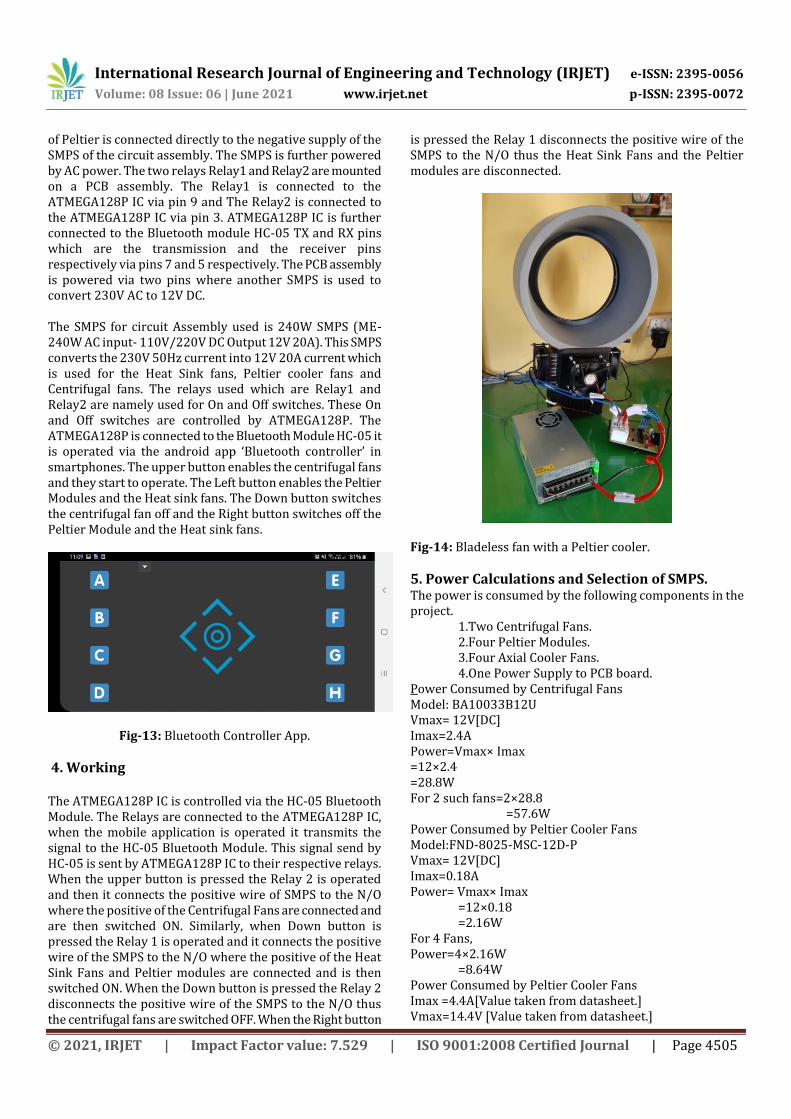
of Peltier is connected directly to the negative supply of the SMPS of the circuit assembly. The SMPS is further powered by AC power. The two relays Relay1 and Relay2 are mounted on a PCB assembly. The Relay1 is connected to the ATMEGA128P IC via pin 9 and The Relay2 is connected to the ATMEGA128P IC via pin 3. ATMEGA128P IC is further connected to the Bluetooth module HC-05 TX and RX pins which are the transmission and the receiver pins respectively via pins 7 and 5 respectively. The PCB assembly is powered via two pins where another SMPS is used to convert 230V AC to 12V DC. The SMPS for circuit Assembly used is 240W SMPS (ME-240W AC input- 110V/220V DC Output 12V 20A). This SMPS converts the 230V 50Hz current into 12V 20A current which is used for the Heat Sink fans, Peltier cooler fans and Centrifugal fans. The relays used which are Relay1 and Relay2 are namely used for On and Off switches. These On and Off switches are controlled by ATMEGA128P. The ATMEGA128P is connected to the Bluetooth Module HC-05 it is operated via the android app ‘Bluetooth controller’ in smartphones. The upper button enables the centrifugal fans and they start to operate. The Left button enables the Peltier Modules and the Heat sink fans. The Down button switches the centrifugal fan off and the Right button switches off the Peltier Module and the Heat sink fans.
Fig-13: Bluetooth Controller App.
4. Working The ATMEGA128P IC is controlled via the HC-05 Bluetooth Module. The Relays are connected to the ATMEGA128P IC, when the mobile application is operated it transmits the signal to the HC-05 Bluetooth Module. This signal send by HC-05 is sent by ATMEGA128P IC to their respective relays. When the upper button is pressed the Relay 2 is operated and then it connects the positive wire of SMPS to the N/O where the positive of the Centrifugal Fans are connected and are then switched ON. Similarly, when Down button is pressed the Relay 1 is operated and it connects the positive wire of the SMPS to the N/O where the positive of the Heat Sink Fans and Peltier modules are connected and is then switched ON. When the Down button is pressed the Relay 2 disconnects the positive wire of the SMPS to the N/O thus the centrifugal fans are switched OFF. When the Right button
is pressed the Relay 1 disconnects the positive wire of the SMPS to the N/O thus the Heat Sink Fans and the Peltier modules are disconnected.
Fig-14: Bladeless fan with a Peltier cooler.
5. Power Calculations and Selection of SMPS. The power is consumed by the following components in the project. 1.Two Centrifugal Fans. 2.Four Peltier Modules. 3.Four Axial Cooler Fans. 4.One Power Supply to PCB board. Power Consumed by Centrifugal Fans Model: BA10033B12U Vmax= 12V[DC] Imax=2.4A Power=Vmax× Imax =12×2.4 =28.8W For 2 such fans=2×28.8 =57.6W Power Consumed by Peltier Cooler Fans Model:FND-8025-MSC-12D-P Vmax= 12V[DC] Imax=0.18A Power= Vmax× Imax =12×0.18 =2.16W For 4 Fans, Power=4×2.16W =8.64W Power Consumed by Peltier Cooler Fans Imax =4.4A[Value taken from datasheet.] Vmax=14.4V [Value taken from datasheet.]

International Research Journal of Engineering and Technology (IRJET) e-ISSN: 2395-0056
Volume: 08 Issue: 06 | June 2021 www.irjet.net p-ISSN: 2395-0072
© 2021, IRJET | Impact Factor value: 7.529 | ISO 9001:2008 Certified Journal | Page 4506
Th=273+30[Ambient Atmospheric Temperature.] =303K ΔTmax=66K[Value taken from datasheet.] αm =Vmax/Imax =14.4/303 =0.047524/K Rm=((Th-ΔTmax)/Th)(Vmax/Imax) =((303-66)/303)(14.4/6.4) =1.7599Ω Km=((Th-ΔTmax)/2ΔTmax)(VmaxImax/Th) =((303-66)/(2(66)))((14.4×6.4)/303) =0.54610W/K P= αm×I×( Th-Tc) + [(I)2×Rm] =(0.047524) ×(6.4) × (303-278)+[(6.4)2×1.7599] =79.6889W Total Power from SMPS, {Power from SMPS} = {Power Consumed by Centrifugal Fan} + {Power consumed by Peltier Cooler Fans} + {Power Consumed by Peltier Modules} Power= 57.8+8.64+318.756 =385.196W SMPS available are of 360W and 480W, selected SMPS must be 360W or 480W for better performance. As a result, there will be variation of values of temperatures obtained.
6. Results and Discussion. 6.1 Velocity Measurement. The velocity of the air coming out of the hoop is measured with the help of an anemometer. The hand-held anemometer is held in front of the hoop from where the air is coming out. At the different locations of the hoop, the velocity is measured. The velocity of air is also measured at 5,10,15,20,25,30,35,40cms at four corners of the hoop i.e top corner, right corner, left corner, right corner, bottom corner of the airfoil. The values are as follows:
Table-2: Variation of velocity at different dimension and distance of the fan.
7.2 Temperature Measurement. The outlet air temperature for different the ambient atmospheric temperature was noted down. The temperature of the outlet of air was noted down using the LM35 sensor circuit. The Peltier sensor was first turned on for five minutes to reach a steady state. The outlet velocity was then measured. The inlet air entering is assumed to have temperature ambient air temperature T0.
Table-3: Outlet temperature of Air for given ambient temperatures.
Ambient Air Temperature.
Inlet Air Temperature = Ambient Air Temperature.
Outlet Air Temperature.
310C 310C 290C
320C 320C 310C 290C 290C 290C 280C 280C 270C
A temperature difference of 10C - 20C is obtained or sometimes temperature difference is not obtained.
7.3 Aerodynamic Analysis of the Hoop. A standardized airfoil was taken from the research paper ‘Numerical Investigation of 60cm diameter airfoil’, their model with approximate same size and shape was created for the hoop. The diameter of the hoop was fixed to 60cm and a mass flow rate of 50L/s is given. Different models in fluent were tested and the velocity contour was compared. Some models take a lot of computational time. The most suitable results for velocity analysis were found with the Transition SST (4 eqn) viscous model. Comparing the magnitude of the velocity of air coming from the top of the hoop is more than the magnitude of the velocity of the air coming from the bottom. The magnitude of the velocity of air is approximately 4m/s which is the same in both. Hence, the transition SST model is suited for this analysis.
The hoop is first designed on Ansys DesignModeler. The hoop is given an enclosure of 0.8m x 0.2m x 0.1m. The mass flow rate of a single fan was calculated using the anemometer. At the outlet of the centrifugal fan, the velocity of the air was found to be 6.4m/s(vfan=6.4m/s). [Assuming density of air ρ=1.225 kg/s, Area of the fan, Afan=29mm × 54mm] Mass Flow Rate of the fan, m’=ρAfanvfan
m’=(1.225)(29 × 10-3 ×54 ×10-3)(6.4) =0.012277kg/s. Mass Flow Rate of two centrifugal fan m’= 2 × 0.012277 = 0.02455kg/s A fluid domain is made with Inlet made below and outlet as shown in Fig15.
Distance. (in cms)
Velocity at Top corner. (m/s)
Velocity at Right corner. (m/s)
Velocity at the Bottom corner. (m/s)
Velocity at the Left corner. (m/s)
5 2.4 2.3 1.8 2.3 10 1.8 1.7 1.8 1.7 15 1.6 1.5 1.7 1.5 20 1.6 1.4 1.5 1.4 25 1.3 1.2 1.1 1.2 30 1.4 1.2 1.1 1.4 35 1.2 1.1 1.1 1.1 40 1.1 0.9 0.8 0.9

International Research Journal of Engineering and Technology (IRJET) e-ISSN: 2395-0056
Volume: 08 Issue: 06 | June 2021 www.irjet.net p-ISSN: 2395-0072
© 2021, IRJET | Impact Factor value: 7.529 | ISO 9001:2008 Certified Journal | Page 4507
Fig-15: Outlet and Inlet of the fluid domain.
At the inlet, the magnitude of 0.02455kg/s is given at atmospheric pressure at the outlet. Planes are plotted at a 5cm distance away and at each distance, the local velocity contour is plotted. The magnitude of the velocity of air at the upper hoop is compared with the observed values.
Sr. No
Velocity of Air on Upper Side of Model Experimentally (m/s)
Velocity of Air on Upper Side By Ansys (m/s)
Distance (m)
1 2.4 2.435 0
2 1.8 1.866 0.05
3 1.75 1.74 0.1
4 1.6 1.603 0.15
5 1.4 1.478 0.2
6 1.4 1.44 0.25
7 1.3 1.42 0.3
Mass of Air Induced.
The mass flow rate of air induced is found out on Ansys. The analysis is run with given input values and the plane at which the air leaves the hoop is selected, the mass flow rate at that plane is calculated using a function calculator, (here plane 2). The mass flow rate of the plane behind the fan is calculated using a function calculator (here plane 9). Mass Flow Rate of Air at Plane 2 = 0.02455kg/s, Mass Flow Rate of Air at Plane 9= 5.63x10⁻⁶ kg/s
Fig-16: Plane 2 merged with Fig-17:Plane 9 merged
Outlet of the hoop. before the fan outlet.
Now,
{Mass Flow Rate of Air induced}={Mass Flow Rate of Air at Plane 2} – {Mass Flow Rate of Air at Plane 9} – {Mass Flow Rate of Air at Inlet}
= 0.02457kg/s - 5.63x10⁻⁶ kg/s – 0.02455kg/s
= 1.437x10⁻⁵kg/s.
Percentage of Mass Flow Rate Induced =
x100
= x100 = 0.0585%
Thus, amount of air induced is very negligible.
7.4 Conclusion
The following conclusion made from this project:
This project explains the complete manufacturing of Bladeless fan with TEC along with its assembly.
The sheet metal manufacturing process of each component is explained in detailed manner.
The circuit assembly with the electrical components along with its interface is also explained.
The fan provides air of velocity of magnitude 1.3m/s up to a distance of 30cm from the face.
The fan is successful in lowering the temperature of the air which is sucked in up to 20C.

International Research Journal of Engineering and Technology (IRJET) e-ISSN: 2395-0056
Volume: 08 Issue: 06 | June 2021 www.irjet.net p-ISSN: 2395-0072
© 2021, IRJET | Impact Factor value: 7.529 | ISO 9001:2008 Certified Journal | Page 4508
The fan is compact and can cool air without the need for a refrigerant, compressor, expansion device.
7.5 Future Scope
Centrifugal fan with a high mass flow rate if used will suck more amount of air which used with properly shaped of air can multiply the amount of air sucked in.
When air moves over the cold chamber there is very less contact time with the cold chamber, due to which there is very little reduction in the temperature of air sucked in, if proper heat exchanger (copper tubes with water as cold fluid) and baffles are used in cold chamber there will be more contact of air which will lead to more cooling.
If proper permutation and combination of the cross- section of hoop airfoil is made then there will be more air on the outside, the process for which is explained.
ACKNOWLEDGEMENT
We would like to express our deep gratitude to Prof. Ratnam Gujar our guide for her patient guidance, encouragement, supervision, formation of group in all respect for this paper.
Also thanks to Mr. Akshay V. Deshmukh in analysis work for this project.
REFERENCES
[1] M. Jafari, H. Afshin, B. Farhaneih, H. Bozorgasareh, “Experimental and Numerical Investigation of 60cm Diameter Bladeless Fan” Article in Journal of Applied Fluid Mechanics · March 2016. ISSN 1735-3572, EISSN 1735-3645.
[2] Sukmaji Indro Cahyono, Abdul Hapid, Miftahul Anwar, Sunarto Kalek, Kuncoro Dihardjo, Budi Santoso “Computational Fluid Dynamic Simulation on Bladeless Fan As Active Cooling Application” November 2018. DOI: 10.1109/ICSEEA.2018.8627098.
[3] M. Jafari, H. Afshin, B. Farhanieh, A.Sojoudi “Numerical Investigation of Geometric Parameter Effects on the Aerodynamic performance of a
Bladeless Fan” March 2017. DOI:10.1016/j.aej.2015.11.001
[4] Manisha Daiya “Design Study of a Bladeless Fan “Air Multiplier”” Article in IJRTI Volume3, Issue 10.
[5] Mr. Raju Goodley, Dr. S.C.V Ramana Murty Naidu, Mr. D. Vekant, Mr. D. Jemin Chakravarthy, Mr. K. Kalyan Reddy, Mr. B. Sathish “Fabrication and Performance Study of Thermoelectric Refrigerator” IRJET Volume 7, Issue 7, May 2020. E-ISSN: 2395-0056 P-ISSN: 2395-0072.
[6] Poonam V. Gaikwad “Bluetooth Based Smart Automation System Using Android” IJSR, Volume 6, Issue 5, May 2017. ISSN (Online): 2319-7064.