Embed Size (px)
Citation preview

Part No. 7291393 (Rev. D 6/11/07)
How to operate yourEcoWater SystemsWater Conditioner
EcoWater Systems Conditioner
with Remote (ECR)
EcoWater Systems Refiner
with Remote (ERR)
SERIES
3500 & 3502
EcoWater Systems LLCP.O. Box 64420, St. Paul MN 55164-0420
OWNER’S MANUAL
PRINTED IN U.S.A.
ERR 3500R20 & ERR 3502R30 are Tested andCertified by NSF International and WQA againstNSF/ANSI Standard 42 for chlorine taste and odor.
Systems Tested and Certified by NSF International andWQA against NSF/ANSI Standard 44 for softener perform-ance and the reduction of barium and radium 226/228.
Downloaded from www.Manualslib.com manuals search engine

2
SAFETY GUIDES
Follow the installation instructions carefully. Failure toinstall the EcoWater Systems conditioner properly voids
the warranty.
Before you begin installation, read this entire manual.Then, obtain all the materials and tools you will need tomake the installation.
Check local plumbing and electrical codes. Theinstallation must conform to them.
Use only lead-free solder and flux for all sweat-solderconnections, as required by state and federal codes.
Use care when handling the EcoWater Systems condi-tioner. Do not turn upside down, drop, or set on sharpprotrusions.
Do not locate the EcoWater Systems conditioner wherefreezing temperatures occur. Do not attempt to treatwater over 120°F. Freezing, or hot water damage
voids the warranty.
Avoid installing in direct sunlight. Excessive sun heatmay cause distortion or other damage to non-metallicparts.
The EcoWater Systems conditioner requires a minimumwater flow of 3 gallons per minute at the inlet. Maximum
allowable inlet water pressure is 125 psi. If daytimepressure is over 80 psi, nighttime pressure may exceedthe maximum. Use a pressure reducing valve if neces-sary (Adding a pressure reducing valve may reduce theflow).
The EcoWater Systems conditioner works on 24 volt, 60
Hz electrical power only. Be sure to use the includedtransformer and plug it into a nominal 120V, 60 Hzhousehold outlet that is in a dry location only, ground-ed and properly protected by an over current device suchas a circuit breaker or fuse. If transformer is replaced,use only the authorized service, Class II, 24V, 10 VAtransformer.
This system is not intended to be used for treating waterthat is microbiologically unsafe or of unknown qualitywithout adequate disinfection before or after the system.
If conditioner is being used to reduce barium and/or radi-um 226 and 228, please verify performance by contact-ing 612-607-1700, ext. 6470 for testing treated watersupply or check the water testing section of your localphone directory.
NOTE: This equipment has been tested and found tocomply with the limits for a Class B digital device, pur-suant to Part 15 of the FCC Rules. These limits aredesigned to provide reasonable protection against harm-ful interference in a residential installation. This equip-ment generates, uses, and can radiate radio frequencyenergy and, if not installed and used in accordance withthe instructions may cause harmful interference to radiocommunications. However, there is no guarantee thatinterference will not occur in a particular installation. Ifthis equipment does cause harmful interference to radioor television reception, which can be determined by turn-ing the equipment off and on, the user is encouraged totry to correct the interference by one or more of the fol-lowing measures:
� Reorient or relocate the receiving antenna.
� Increase the separation between the equipment andreceiver.
� Connect the equipment into an outlet on a circuit dif-ferent from that to which the receiver is connected.
� Consult the dealer or an experienced radio/TV tech-nician for help.
Changes or modifications not expressly approved byEcoWater Systems could void the user’s authority tooperate the equipment.
This device complies with Industry Canada StandardRSS-210. Operation is subject to the following two con-ditions: (1) this device may not cause interference, and(2) this device must accept any interference, includinginterference that may cause undesired operation of thedevice.
Ce dispositif est conforme avec la norme CNR-210d’Industrie Canada. Le fonctionnement du dispositifest sujet aux deux conditions suivantes: (1) le dispositifne doit pas causer de brouillage, et (2) le dispositif doitaccepter tous brouillages, incluant tous brouillages quipeut nuire au bon fonctionnement du dispositif.
European Directive 2002/96/EC requires allelectrical and electronic equipment to be dis-posed of according to Waste Electrical andElectronic Equipment (WEEE) requirements.This directive or similar laws are in placenationally and can vary from region to region.Please refer to your state and local laws forproper disposal of the equipment.
TABLE OF CONTENTS Page
Warranty . . . . . . . . . . . . . . . . . . . . . . . . . . . . . . . . . . .3
Planning Installation . . . . . . . . . . . . . . . . . . . . . . . . . .4
Unpacking . . . . . . . . . . . . . . . . . . . . . . . . . . . . . . . . . .5
Installation . . . . . . . . . . . . . . . . . . . . . . . . . . . . . . . .5-7
Conditioner Operation . . . . . . . . . . . . . . . . . . . . . .8-21
Remote Operation . . . . . . . . . . . . . . . . . . . . . . . .22-30
Service Information . . . . . . . . . . . . . . . . . . . . . . .31-34
Refilling with Salt . . . . . . . . . . . . . . . . . . . . . . . . . . .31
Troubleshooting . . . . . . . . . . . . . . . . . . . . . . . . . .34-37
Dimensions . . . . . . . . . . . . . . . . . . . . . . . . . . . . . . . .38
Specifications . . . . . . . . . . . . . . . . . . . . . . . . . . . . . .39
Repair Parts . . . . . . . . . . . . . . . . . . . . . . . . . . . . .40-43
ECOWATERS Y S T E M S
Table of Contents & Safety Guides
Downloaded from www.Manualslib.com manuals search engine

3
LIMITED WARRANTYEcoWater Systems LLC
Advantage Warranty
Series ECR & ERR 3500 Water SystemCongratulations! You have just purchased the highest quality water conditioningproduct on the market. To register your warranty, complete the enclosed WarrantyRegistration Card and mail it within 30 days of purchase.
To whom is this warranty extended?
EcoWater Systems LLC warrants its products to the original owner and guaranteesthat the products will be free from defects in materials and workmanship from the orig-inal date of installation.
How does my warranty work?
If, during the respective warranty period, a part proves, after inspection by EcoWater,to be defective, EcoWater will, at its sole option repair or replace that part at nocharge, other than normal shipping, installation or service charges.
What is covered by the warranty?
EcoWater Systems LLC guarantees that,for the LIFETIME of the original owner, the SALT TANK and the MINERAL TANK willnot rust, corrode, leak, burst, or in any other manner fail to perform their proper func-tions and that,for a period of TEN YEARS, the VALVE BODY will be free of defects in materials andworkmanship and will perform its proper function and that,for a period of FIVE YEARS, the ELECTRONIC FACEPLATE and ALL OTHER
PARTS, including the HYDROLINK™ REMOTE will be free of defects in materials
and workmanship and will perform their normal functions.Only on models designated as ERR on the rating decal, is the resin bed guaranteed,for the lifetime of the original owner, to be free of defects in materials and workman-ship and to remove chlorine taste and odor from a municipal water supply.
How do I obtain warranty service?
Should you need service, your local, independent EcoWater Dealer is only a phonecall away.PHONE:____________________________________________________________To obtain warranty service, notice must be given, within thirty (30) days of the discov-ery of the defect, to your local EcoWater Systems dealer.
If I need a part replaced after the factory warranty expires, is the replacement
part warranted?
Yes, EcoWater Systems LLC warrants FACTORY REPAIRS as well as all REPLACE-MENT PARTS for a period of 90 DAYS. This warranty does not include normal ship-ping, installation or service charges.
Are any additional warranties available?
We are pleased to say, YES! EcoWater Systems LLC sells an EXTENDED, PARTSONLY WARRANTY for the ELECTRONICS portion of your product. This warranty iscalled the "Perfect Ten" and extends the five year warranty on the electronic FACE-PLATE, WIRING HARNESS, DRIVE MOTOR, TRANSFORMER, POWER CORD,SENSOR HOUSING, and MICRO SWITCHES to a total of TEN YEARS from the dateof original installation. Your local dealer will provide details regarding this warranty orwill refer you to the factory for additional information. In addition, the 3500 SERIESproduct carries the CREST OF EXCELLENCE GUARANTEE that, should you expe-rience a repetitive problem that remains uncorrected, EcoWater will, during the FIRSTYEAR OF INSTALLATION, replace the product with the exact or comparable prod-uct.* This guarantee may be subject to normal shipping and installation or servicecharges.
General Provisions
The above warranties are effective provided the water conditioner is operated atwater pressures not exceeding 125 psi, and at water temperatures not exceeding
120°F (and on a municipal chlorinated water supply - models designated as ERR on
the rating decal); provided further that the water conditioner is not subject to abuse,misuse, alteration, neglect, freezing, accident or negligence; and provided further thatthe water conditioner is not damaged as the result of any unusual force of nature suchas, but not limited to, flood, hurricane, tornado or earthquake. EcoWater Systems LLCis excused if failure to perform its warranty obligations is the result of strikes, govern-ment regulation, materials shortages, or other circumstances beyond its control.
*THERE ARE NO WARRANTIES ON THE WATER CONDITIONER BEYONDTHOSE SPECIFICALLY DESCRIBED ABOVE. ALL IMPLIED WARRANTIES,INCLUDING ANY IMPLIED WARRANTY OF MERCHANTABILITY OR OF FITNESSFOR A PARTICULAR PURPOSE, ARE DISCLAIMED TO THE EXTENT THEYMIGHT EXTEND BEYOND THE ABOVE PERIODS. THE SOLE OBLIGATION OFECOWATER SYSTEMS LLC UNDER THESE WARRANTIES IS TO REPLACE ORREPAIR THE COMPONENT OR PART WHICH PROVES TO BE DEFECTIVE WITH-IN THE SPECIFIED TIME PERIOD, AND ECOWATER IS NOT LIABLE FOR CON-SEQUENTIAL OR INCIDENTAL DAMAGES. NO ECOWATER DEALER, AGENT,REPRESENTATIVE, OR OTHER PERSON IS AUTHORIZED TO EXTEND OREXPAND THE WARRANTIES EXPRESSLY DESCRIBED ABOVE.
Some states do not allow limitations on how long an implied warranty lasts or exclu-sions or limitations of incidental or consequential damage, so the limitations andexclusions in this warranty may not apply to you. This warranty gives you specificlegal rights, and you may have other rights which vary from state to state. This war-ranty applies to consumer-owned installations only.
GUARANTEE
BOND
The Safeco Insurance Company of America has issuedits bond in the form shown below, guaranteeing full per-formance by EcoWater Systems LLC.
SAFECO INSURANCE COMPANY OF AMERICA, here-inafter called “Surety,” guarantees unto Bank of NewYork as Trustee holding said Guarantee Bond under theterms of a Trust Agreement dated April 9, 2003, for theuse and benefit of original purchasers of residentialEcoWater Systems Units within the Continental UnitedStates, as described herein, that EcoWater Systems LLCwill discharge the obligations of the “EcoWater BondedParts and Service Guarantee Policy.”
PROVIDED, HOWEVER, that:
1. Liability of Surety hereunder shall not exceed the sumof FIVE HUNDRED AND 00/100th DOLLARS ($500.00)as to any one installation, and shall not exceed the sumof FIVE HUNDRED THOUSAND AND 00/100th DOL-LARS ($500,000.00) in the aggregate, and
2. There shall be no liability hereunder as to any pur-chaser to whom there has not been issued at the time ofinstallation and purchase completed registration cardwhich is enclosed with a facsimile of this bond, and whohas not returned such card in accordance with this guar-antee.
3. Claim must be made by such original purchaser inwriting within 30 days from the expiration of these guar-antees upon EcoWater Systems LLC, P.O. Box 64420,St. Paul, MN 55164, to perform the terms of said guaran-tee, and notice of any default on such guarantee must besent to Surety at its address by Registered Mail.
SAFECO INSURANCE COMPANY OF AMERICA
This is to certify that the original of the above guaranteeand bond is on file with Bank of New York.
BANK OF NEW YORK
As Trustee
ECOWATERS Y S T E M S
Warranty
Downloaded from www.Manualslib.com manuals search engine

4
INLET / OUTLET PLUMBING OPTIONS
� ALWAYS INSTALL either an EcoWater Systemsbypass valve #7214383, or a 3-valve bypass system.Bypass valves allow you to turn off water to the sof-tener for repairs if needed, but still have water inhouse pipes.
OTHER REQUIREMENTS
� A drain is needed for recharge discharge water. Afloor drain is preferred, close to the EcoWaterSystems conditioner. A laundry tub, standpipe, etc.,are other options (See Figure 2).
� A 120V, 60 Hz, grounded, continuously “live” electri-cal outlet is needed, in a dry location within 10 feet ofthe EcoWater Systems conditioner.
NOTE: The Commonwealth of Massachusetts plumbingcode 248-CMR shall be adhered to. A licensed plumbershall be used for this installation.
STANDPIPE
1--1/2”airgap
drainhose
1--1/2”airgap
drainhose
LAUNDRY TUB
DRAIN OPTIONS
floor drain
valve drain hose
brinetankoverflowhose
TWO--TANKMODEL
1--1/2”airgap
INLET
OUTLET
3-- valvebypass system
inlet valve
outlet valve
bypass valve
floor drain
NOTE: Faceplate and supportnot shown for clarity of drawing.
Tie or wire valve drain hose in placeto keep over floor drain.
brine tankoverflow hose
valve drain hose
CABINETMODEL
1--1/2”airgap
120V, 60Hzoutlet
transformer(supplied)
tocontroller
INLET
OUTLET
HARDWATERHARD
WATER
CONDITIONEDWATER
bypass valve#7214383
tocontroller
FIG. 1
TYPICAL INSTALLATION DRAWINGS
FIG. 2
ECOWATERS Y S T E M S
Planning Installation
Downloaded from www.Manualslib.com manuals search engine

5
4. INSTALLING THREE-VALVE BYPASS
If installing a 3-valve bypass system, plumb as neededusing Figure 1 as a guide. When installing sweat cop-per, be sure to use lead-free solder and flux, requiredby federal and state codes. Use pipe joint compoundon outside pipe threads.
5. ASSEMBLE INLET & OUTLET PLUMBING
Measure, cut, and loosely assemble pipe and fittingsfrom the main water pipe (or from the bypass valvesinstalled in Step 4), to the inlet and outlet copper tubes,installed in Step 2b.
Be sure hard water supply pipe goes to the valve
inlet side. Trace the water flow direction to be sure.
6. CONNECT INLET & OUTLET PLUMBING
a. SOLDERED COPPER
(1) Thoroughly clean and flux all joints.
(2) Pull the plastic “C'' clips and remove the inlet andoutlet tubes from the valve. Remove o-rings from thetubes. DO NOT solder with tubes in the valve.
Soldering heat will damage the valve.
NOTE: If installing a ground as shown in Figure 4A,place ground clamps on copper tubes before soldering(See Step 7a).
(3) Make all solder connections. Be sure to keep fit-tings fully together, and pipes square and straight.
continued
1. UNPACKING
EcoWater Systems conditioner models R70 and R50Sare shipped from the factory in two cartons. These con-tain resin tank/controller assembly in one carton and thebrine tank, cover, bag(s) of small parts needed toassemble and install the unit, plus this manual, in theother.
EcoWater Systems conditioner models R20, R30 andR40 are shipped from the factory in one master carton.The carton also includes a bag of small parts needed toassemble and install the unit, plus this manual.
Thoroughly check the EcoWater Systems conditioner forpossible shipping damage and parts loss. Also inspectand note any damage to the shipping carton. Notify thetransportation company if damage is present. EcoWaterSystems is not responsible for in-transit damages.
Remove and discard (RECYCLE) all packing materials.We suggest you keep the small parts in the bag(s) untilyou are ready to use them. Minimal assembly is neededon all two tank models.
2. INSTALL BYPASS VALVE and/or COP-
PER TUBES
a. If installing an EcoWater Systems Bypass Valve,put lubricated o-ring seals onto both bypass valve ports(See Figure 3B). Carefully slide the bypass valve intothe softener valve and install the "C" clips.
b. Slide a lubricated o-ring seal onto each of the coppertubes. Carefully insert the copper tubes into the bypass
o--ring (2)
turbinesupport
clip (2)
copper tube (2)
VALVE INLET
coppertube o--ring
clipturbinesupport
BypassValveInstallation
coppertube (2)
A.
B.
o--ring (2)
FIG. 3
ECOWATERS Y S T E M S
Unpacking & Installation
valve (See Figure 3B), or intothe softener valve (Figures 3 &3A). Then install the “C'' clips.
NOTE: For lubrication, use sili-cone grease approved forpotable water supplies.
3. TURN OFF WATER
SUPPLY
a. Close the main water supplyvalve near the well pump orwater meter.
b. Shut off the electric or fuelsupply to the water heater.
c. Open high and low faucets todrain all water from the housepipes.
Downloaded from www.Manualslib.com manuals search engine

6
b. THREADED PIPE
(1) Apply pipe joint compound to all outside pipethreads.
(2) Tighten all threaded joints.
(3) If soldering to the inlet and outlet tubes, observeStep 6a above.
c. CPVC PLASTIC PIPE
(1) Clean, prime and cement all joints, following themanufacturer's instructions supplied with the plasticpipe and fittings.
(2) If soldering to the inlet and outlet tubes, observestep 6a above.
7. COLD WATER PIPE GROUNDING
The house cold water pipe (metal only) is often used asa ground for the house electrical system. The 3-valvebypass type of installation, shown in Figure 1, will main-tain ground continuity. If you use the plastic bypass,continuity is broken. To restore the ground, do eitherstep 7a or 7b following.
a. Use the included ground clamp kit (included) to makea jumper across the inlet and outlet copper tubes (SeeFigure 4A).
b. Install a #4 copper wire across the removed sectionof main water pipe, securely clamping at both ends(See Figure 4B) – parts not included.
8. INSTALL VALVE DRAIN HOSE
NOTE: See valve drain options on Page 4.
a. Elevating the drain hose may cause back pressurethat could reduce the brine draw during recharge. Ifraising the drain line overhead is required to get to thedrain point, measure the inlet water pressure to the sof-tener first. For inlet pressures between 20 and 50 psi,do not raise higher than 8 feet above the floor. For inletpressure above 50 psi, the drain line may be raised to amaximum height of 14 feet.
b. Connect a length of 1/2" I.D. hose (check codes) tothe valve drain elbow, on the controller. Use a hoseclamp to hold the hose in place. Route the hose outthrough the notch in the back of the top cover.
c. Run the hose to the floor drain, and as typicallyshown in Figure 1, tie or wire the end to a brick or otherheavy object. This will prevent “whipping” duringrecharges. Be sure to provide a 1-1/2" minimum airgap, to prevent possible sewer water backup.
ground wire
clamp (2)
nozzle &venturi
o--ring
elbow
Note: To ease brine tubing con-nection, use the elbow and o--ringseal as shown. Lubricate the o--ring and insert into the elbow. Turnthe elbow on and tighten. Then,back--off up to one turn, as need-ed.
B
A 3 -- Valve Bypass
OUTLETVALVE
INLETVALVE
BYPASSVALVE
to conditionerfrom conditioner
EcoWater SystemsBypass Valve
D for SERVICE:-- Open the inlet and outlet
valves.-- Close the bypass valve.
D for BYPASS:-- Close the inlet and outlet
valves.-- Open the bypass valve.
PUSH INfor bypass
PULL OUTfor servicenut--ferrule
screen
groundclamp
brinetubing
FIG. 4 FIG. 5 FIG. 6
ECOWATERS Y S T E M S
Installation
9. INSTALL BRINE TANK OVERFLOW HOSE
a. Connect a length of 1/2" I. D. hose to the brine tankoverflow elbow and secure in place with a hose clamp.
b. Run the hose to the floor drain, or other suitabledrain point no higher than the drain fitting on thetank. If the tank overfills with water, the excess waterflows to the drain point.
10. On Two-tank models, connect the brine tub-
ing to the nozzle and venturi housing.
Downloaded from www.Manualslib.com manuals search engine

7
11. PRESSURE TESTING FOR LEAKS
To prevent excessive air pressure in the EcoWater
Systems conditioner and plumbing system, do the
following steps EXACTLY in order:
a. Fully open two or more conditioned cold waterfaucets nearby the EcoWater Systems conditioner.
b. Place the bypass valve(s) in bypass position (SeeFigure 6).
c. Fully open the main water supply valve. Watch untilthe flow from the opened faucets becomes steady, withno spurting or air bubbles.
d. EXACTLY as follows, place bypass valve(s) intoservice:
(1) SINGLE BYPASS VALVE: Slowly move the valvestem toward service position, pausing serveral timesto allow the unit to pressurize slowly.
(2) 3-VALVE BYPASS: Fully close the bypass valveand open the outlet valve. Slowly open the inlet
valve, pausing serveral times to allow the unit to pres-surize slowly.
e. After about three minutes, open a hot water faucetfor one minute, or until all air is expelled, then close.
f. Close all cold water faucets and check your plumbingwork for leaks.
12. ADD WATER AND SALT TO THE BRINE
TANK
a. Using a pail or garden hose, add about 3 gallons ofwater into the brine tank. DO NOT pour into thebrinewell.
b. Add salt to the brine tank. It is recommended to fillthe brine tank no more than 1/2 full. Level the saltwhen finished adding. You can use most water condi-tioner salts, but it must be clean. Recommendednugget, pellet or coarse solar salts have less than 1%impurities. Salt storage capacity is shown on page 38.
NOTE: See page 31 for additional information on salt.
13. SANITIZING THE ECOWATER SYSTEMS
CONDITIONER
Care is taken at the factory to keep your EcoWaterSystem conditioner clean and sanitary. However, dur-ing shipping, storage, installing and operating, bacteriacould get into the unit. For this reason, sanitizing asfollows is suggested* when installing.
continued
*Recommended by the Water Quality Association. On some
water supplies, the EcoWater System Unit may need periodic
disinfecting.
a. Remove the brinewell cover and pour about 1-1/2 oz.(2 to 3 tablespoons) of common household bleach intothe softener brinewell. Clorox, Linco, Bo Peep, WhiteSail, Eagle, etc., are brand names of bleach readilyavailable. Replace the brinewell cover.
b. The final step in the sanitizing procedure is done asyou complete the following steps, including electroniccontroller programming on page 8.
14. CONNECT TRANSFORMER
Plug the transformer into a continuously “live,” ground-ed, 120V, 60Hz house electrical outlet, in a dry locationand approved by local codes. The unit works on 24V
only. Do not connect without the transformer.
15. PROGRAM THE ELECTRONIC CON-
TROLLER
Follow the Setup Procedure on Page 8 to program theelectronic controller with basic operating information,such as time and water hardness. After completingSteps 1 through 14 of the setup procedure on Page 8,continue with Step 16 below.
16. START A RECHARGE
From the rolling status screens, press the SELECT (�)button to display the Main menu. Make sure
Recharge is highlighted, then press SELECT (�).Press DOWN (�) to scroll to Recharge Now, thenpress SELECT (�) twice. You should hear the valvemotor run as the EcoWater Systems conditioner beginsrecharging. This recharge draws the sanitizing bleachinto and through the conditioner. Any air remaining inthe unit is purged to the drain.
17. RESTART THE WATER HEATER
Turn on the electric or fuel supply to the water heater,and light the pilot, if applies.
NOTE: The water heater is filled with hard water and,as hot water is used, it refills with conditioned water. Ina few days, the hot water will be fully conditioned. Tohave fully conditioned hot water immediately, wait untilthe recharge (Step 16) is complete, then drain the waterheater until water runs cold.
18. CONNECT TO THE REMOTE
Unpack the remote and install the batteries, as detailedon Page 22. Then, follow the “Connecting to Remote”procedure on Page 10.
ECOWATERS Y S T E M S
Installation
Downloaded from www.Manualslib.com manuals search engine

8
SETUP PROCEDURE
When the EcoWater Systems softener is plugged in forthe first time, a beep sounds and the display brieflyshows a logo, followed by model information. Next, aseries of six “wizard” screens prompts you to enterbasic operating information:
FIG. 8
1. LANGUAGE If the desired language already has ablack dot next to it (See Figure 8), go to Step 2.
Otherwise, press the softener’s DOWN (�) or UP(�) buttons to scroll to the desired language, thenpress the SELECT (�) button to choose it.
2. Press the SELECT (�) button to advance to the next“wizard” screen.
FIG. 9
3. SYSTEM UNITS If the desired system already has ablack dot next to it (See Figure 9), go to Step 4.
Otherwise, press the DOWN (�) or UP (�) buttonsto scroll to the desired system, then press the
SELECT (�) button to choose it.
4. Press the SELECT (�) button.
FIG. 10
FIG. 11
FIG. 12
FIG. 13
FIG. 14
6. Press the SELECT (�) button.
8. Press the SELECT (�) button.
9. SALT LEVEL Press the UP (�) or DOWN (�) but-tons to set the salt level (See Figure 12). It shouldmatch the lowest number visible on the brinewelldecal above the salt.
10. Press the SELECT (�) button.
11. IRON LEVEL Press the UP (�) or DOWN (�) but-tons to set the value for iron in your water (SeeFigure 13). The conversion factor is 3 grains per 1ppm of clear water iron.
12. Press the SELECT (�) button. The screen willshow “Setup complete!” (See Figure 14).
13. If, at this point, you want to go back and make
changes, press the DOWN (�) button to scroll toRedo setup, then press the SELECT (�) buttontwice to repeat the six “wizard” screens.
14. If no changes are desired, make sure Run softener
has a black dot next to it (See Figure 14) and press
the SELECT (�) button. The softener begins nor-mal operation, described on the next page.
FIG. 7
Display LEFTButton
RIGHTButton
UPButton
DOWNButton
E.A.S.E.Port
SELECTButton
5. CURRENT TIME Press the DOWN (�) or UP (�)buttons to set the current time (See Figure 10). Holdthe button down to rapidly advance. Be sure that AMor PM is correct. If the system units were set to met-ric in Step 3, the clock will be in 24-hour format.
ECOWATERS Y S T E M S
Conditioner Operation
NOTE: Do not increase the hardness setting tocompensate for iron in your water. Theelectronic control compensates automaticallyafter you set the iron level in Step 11, below.
7. HARDNESS Press the UP (�) or DOWN (�) but-tons to set the value of your water’s hardness (SeeFigure 11).
Downloaded from www.Manualslib.com manuals search engine

9
During normal operation (status screens rolling), press
the softener’s SELECT (�) button to display the Mainmenu (See Figure 16). This menu and its subsidiaryscreens are used to control these softener operations:
�Recharge (See Page 12)�Salt settings
�Salt level (See Page 11)�Low salt alarm (See Page 11)�Salt type (See Page 11)
�Basic settings
�Current time (See Page 12)�Hardness (See Page 13)�Iron level (See Page 13)�Recharge time (See Page 13)�Rolling screens (See Page 14)
�User preferences
�Language (See Page 14)�Time format (See Page 15)�Volume units (See Page 15)�Hardness units (See Page 15)�Weight units (See Page 15)
�System information
�Model information (See Page 16)�Water available (See Page 16)�Daily avg. water used (See Page 16)�Water used today (See Page 16)�Total water used (See Page 16)�Current water flow (See Page 16)�Days powered up (See Page 16)�Last recharge (See Page 16)�Total recharges (See Page 16)
�Advanced settings
�Cycle times
�Backwash time (See Page 17)�2nd backwash (See Page 17)�2nd backwash time (See Page 17)�Fast rinse time (See Page 17)
�Special features
�Efficiency mode (See Page 18)�Max. days between recharges (See Page 18)�Auxiliary control (See Page 19)�Chemical feed volume** (See Page 19)�Chemical feed timer** (See Page 19)�97% feature (See Page 18)�Service reminder (See Page 20)
�Troubleshooting
�Send E.A.S.E. message (See Page 20)�Diagnostics (See Page 21)�Setup changes (See Page 21)
�Connect to remote (See Page 10)
**Only displayed if Auxiliary control is set to Chemical feed.
FIG. 16
MAIN MENU
Pressing the softener’s RIGHT (�) button manuallyadvances to the next screen in the sequence. Pressing
the LEFT (�) button manually returns to the previousstatus screen. If no buttons are pressed for 30 sec-onds, the automatic rolling sequence resumes.
OTHER MESSAGES, ALERTS &
REMINDERS
The softener status screens described above will not bedisplayed in a rolling sequence when one of the follow-ing items is displayed:
�Recharge status (Displayed during recharges,showing valve position and time remaining)
�Add salt or Out of salt (See Page 31)�Current time setting screen instead of status
screens indicates time has been lost, perhaps aftera long power loss. Set the time (See Page 12).
�Service reminder (See Page 20)�Error detected (Contact your dealer for service)
FLASHING BACKLIGHT
The softener’s display is backlit to make it easy to read.The backlight will flash on and off when one or more ofthe following conditions occurs:
�Salt needs to be added�Time needs to be set (Time has been lost)�Service is overdue (Service reminder)�Error condition
The flashing will stop after any key is pressed.However, it will start again at Midnight if the underlyingcondition (e.g. low salt level) has not been addressed.
ECOWATERS Y S T E M S
Conditioner Operation
SOFTENER STATUS SCREENS
During normal operation, the EcoWater Systems soften-er’s display shows up to four status screens (Page 14explains how individual screens can be turned on oroff). Each is shown for six seconds, in a rollingsequence (See Figure 15).
FIG. 15
*
*Water remaining before the next recharge.
Downloaded from www.Manualslib.com manuals search engine
10
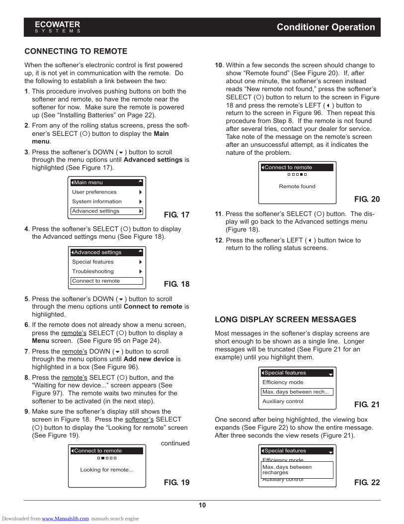
CONNECTING TO REMOTE
When the softener’s electronic control is first poweredup, it is not yet in communication with the remote. Dothe following to establish a link between the two:
1. This procedure involves pushing buttons on both thesoftener and remote, so have the remote near thesoftener for now. Make sure the remote is poweredup (See “Installing Batteries” on Page 22).
2. From any of the rolling status screens, press the soft-
ener’s SELECT (�) button to display the Mainmenu.
3. Press the softener’s DOWN (�) button to scrollthrough the menu options until Advanced settings ishighlighted (See Figure 17).
4. Press the softener’s SELECT (�) button to displaythe Advanced settings menu (See Figure 18).
FIG. 17
FIG. 18
5. Press the softener’s DOWN (�) button to scrollthrough the menu options until Connect to remote ishighlighted.
6. If the remote does not already show a menu screen,
press the remote’s SELECT (�) button to display aMenu screen. (See Figure 95 on Page 24).
7. Press the remote’s DOWN (�) button to scrollthrough the menu options until Add new device ishighlighted in a box (See Figure 96).
8. Press the remote’s SELECT (�) button, and the“Waiting for new device...” screen appears (SeeFigure 97). The remote waits two minutes for thesoftener to be activated (in the next step).
9. Make sure the softener’s display still shows thescreen in Figure 18. Press the softener’s SELECT
(�) button to display the “Looking for remote” screen(See Figure 19).
continued
FIG. 19
10. Within a few seconds the screen should change toshow “Remote found” (See Figure 20). If, afterabout one minute, the softener’s screen insteadreads “New remote not found,” press the softener’s
SELECT (�) button to return to the screen in Figure18 and press the remote’s LEFT (�) button toreturn to the screen in Figure 96. Then repeat thisprocedure from Step 8. If the remote is not foundafter several tries, contact your dealer for service.Take note of the message on the remote’s screenafter an unsuccessful attempt, as it indicates thenature of the problem.
FIG. 20
11. Press the softener’s SELECT (�) button. The dis-play will go back to the Advanced settings menu(Figure 18).
12. Press the softener’s LEFT (�) button twice toreturn to the rolling status screens.
FIG. 21
FIG. 22
LONG DISPLAY SCREEN MESSAGES
Most messages in the softener’s display screens areshort enough to be shown as a single line. Longermessages will be truncated (See Figure 21 for anexample) until you highlight them.
ECOWATERS Y S T E M S
Conditioner Operation
One second after being highlighted, the viewing boxexpands (See Figure 22) to show the entire message.After three seconds the view resets (Figure 21).
Downloaded from www.Manualslib.com manuals search engine

LOW SALT ALARM
Use this feature to program when the electronic controlwill display a low salt alarm. The number of days canbe customized, or the feature can be turned off. Thedefault is 30 days.
1-3. Go to the Salt settings menu by following Steps 1-3 in “Procedure for Two-tank Models” at left.
4. Press the DOWN (�) button to scroll through themenu options until Low salt alarm is highlighted.
5. Press the SELECT (�) button to display the Low saltalarm screen (See Figure 26).
FIG. 23
6. Press the UP (�) or DOWN (�) buttons to changethe number of days. Set the number of days to pro-vide enough time to purchase salt and avoid runninginto hard water. Setting the number of days below 1turns the alarm feature off.
7. Press the SELECT (�) button. The display will goback to the Salt settings menu.
8. Press the LEFT (�) button twice to return to therolling status screens.
SETTING SALT TYPE
Use this feature to program the electronic control withwhich type of salt is used. The default is NaCl.Selecting KCl increases fill time 25% and brine/slowrinse times 12%.
1-3. Go to the Salt settings menu by following Steps 1-3 in “Procedure for Two-tank Models” at left.
4. Press the DOWN (�) button to scroll through themenu options until Salt type is highlighted.
5. Press the SELECT (�) button to display the Salt typemenu (See Figure 27).
FIG. 26
FIG. 27
6. If the desired salt type already has a black dot nextto it (See Figure 27), go to Step 7. Otherwise, press
the softener’s DOWN (�) or UP (�) buttons to scrollto the other salt type, then press SELECT (�) tochoose it.
7. Press the SELECT (�) button. The display will goback to the Salt settings menu.
8. Press the LEFT (�) button twice to return to therolling status screens.
11
SETTING SALT LEVEL
Use this feature when adding salt to the softener.
Procedure for Cabinet Models
1. When the softener is displaying the rolling statusscreens, open the salt lid. The tank light turns onand the Salt level screen appears (See Figure 23).
2. After adding and leveling salt, observe the numbered
decal on the brinewell. Press UP (�) or DOWN (�)to change the salt level to match the lowest numbervisible on the brinewell decal above the salt.
3. Close the salt lid. The tank light turns off and the dis-play goes back to the rolling status screens.
Procedure for Two-tank Models
1. From any of the rolling status screens, press the
SELECT (�) button to display the Main menu.
2. Press the DOWN (�) button to scroll through themenu options until Salt settings is highlighted (SeeFigure 24).
3. Press the SELECT (�) button to display the Salt set-tings menu (See Figure 25).
FIG. 24
FIG. 25
4. Make sure Salt level is highlighted.
5. Press the SELECT (�) button to display the Saltlevel screen (See Figure 23). This screen will notautomatically exit for 15 minutes.
6. After adding and leveling salt, observe the numbered
decal on the brinewell. Press UP (�) or DOWN (�)to change the salt level to match the lowest numbervisible on the brinewell decal above the salt.
7. Press the SELECT (�) button. The display will goback to the Salt settings menu (Figure 25).
8. Press the LEFT (�) button twice to return to therolling status screens. It will also exit automatically ifno buttons are pressed for four minutes.
ECOWATERS Y S T E M S
Conditioner Operation
Downloaded from www.Manualslib.com manuals search engine

12
RECHARGING THE SOFTENER
This feature may be used to assure an adequate supplyof softened water at times of unusually high water use.For example, if you have guests and the “Water avail-able” screen (See Page 16) is at or below 50%, youcould deplete softened water capacity before the nextautomatic recharge. Initiating a manual recharge willrestore 100% softened water capacity after complete.
1. From any of the rolling status screens, press the
SELECT (�) button to display the Main menu.
FIG. 29
2. Make sure Recharge is highlighted (See Figure 28).
3. Press the SELECT (�) button to display theRecharge menu (See Figure 29).
FIG. 28
4. If the desired option already has a black dot next to it(See Figure 29), go to Step 5. Otherwise, press the
DOWN (�) or UP (�) buttons to scroll to the desiredoption, then press SELECT (�) to choose it.
�Automatic cancels a manually scheduled recharge(if it has not already begun) and lets the electroniccontrol determine when to recharge next.�Recharge now begins a recharge immediately
after the SELECT (�) button is pushed again in Step5.�Schedule sets a recharge to begin at the presetrecharge time (set according to the instructions onPage 13).
5. Press the SELECT (�) button. If Recharge now isselected, the display immediately goes to theRecharge status screen (See Figure 30). IfAutomatic or Schedule are selected, the displaygoes back to the Main menu (Figure 28).
SETTING THE CURRENT TIME
When the softener’s electronic control is first poweredup, a “wizard” screen prompts you to set the currenttime (See Page 8). To change the time at a later date,such as after a long power loss:
1. From any of the rolling status screens, press the
SELECT (�) button to display the Main menu.
2. Press the DOWN (�) button to scroll through themenu options until Basic settings is highlighted(See Figure 31).
3. Press the SELECT (�) button to display the Basicsettings menu (See Figure 32).
FIG. 31
FIG. 32
4. Make sure Current time is highlighted.
5. Press the SELECT (�) button to display the Currenttime screen (See Figure 33).
6. Press the UP (�) or DOWN (�) buttons to changethe time. Hold the button down to rapidly advance.Be sure that AM or PM is correct (unless softener isset for a 24-hour clock).
7. Press the SELECT (�) button. The display will goback to the Basic settings menu (Figure 32).
8. Press the LEFT (�) button twice to return to therolling status screens.
FIG. 33
FIG. 30
6. Press the LEFT (�) button (twice from the Rechargestatus screen) to return to the rolling status screens.
ECOWATERS Y S T E M S
Conditioner Operation
Downloaded from www.Manualslib.com manuals search engine

SETTING RECHARGE TIME
When the softener’s electronic control is first poweredup, the default time for starting an automatic recharge is2:00 a.m. This is a good time in most householdsbecause water is not being used. To change this time:
1. From any of the rolling status screens, press the
SELECT (�) button to display the Main menu.
2. Press the DOWN (�) button to scroll through themenu options until Basic settings is highlighted(See Figure 34).
FIG. 35
3. Press the SELECT (�) button to display the Basicsettings menu (See Figure 35).
FIG. 36
FIG. 34
4. Press the DOWN (�) button to scroll through themenu options until Recharge time is highlighted.
5. Press the SELECT (�) button to display theRecharge time screen (See Figure 36).
6. Press the UP (�) or DOWN (�) buttons to changethe recharge time in 1 hour increments. Hold thebutton down to rapidly advance. Be sure that AM orPM is correct (unless softener is set for a 24-hourclock).
7. Press the SELECT (�) button. The display will goback to the Basic settings menu (Figure 35).
8. Press the LEFT (�) button twice to return to therolling status screens.
7. Press the SELECT (�) button. The display will goback to the Basic settings menu.
8. Press the LEFT (�) button twice to return to therolling status screens.
SETTING IRON LEVEL
When the softener’s electronic control is first poweredup, a “wizard” screen prompts you to enter your water’siron level (See Page 8). The conversion factor is 3grains per ppm of clear water iron. To change:
1-3. Go to the Basic settings menu by following Steps1-3 in “Setting Recharge Time” at left.
4. Press the DOWN (�) button to scroll through themenu options until Iron level is highlighted.
5. Press the SELECT (�) button to display the Ironlevel screen (See Figure 38).
FIG. 38
6. Press the UP (�) or DOWN (�) buttons to set thevalue for iron in your water. Hold the button down torapidly advance.
7. Press the SELECT (�) button. The display will goback to the Basic settings menu.
8. Press the LEFT (�) button twice to return to therolling status screens.
SETTING HARDNESS
When the softener’s electronic control is first poweredup, a “wizard” screen prompts you to enter your water’shardness (See Page 8). To change it:
1-3. Go to the Basic settings menu by following Steps1-3 in “Setting Recharge Time” at left.
4. Press the DOWN (�) button to scroll through themenu options until Hardness is highlighted.
5. Press the SELECT (�) button to display theHardness screen (See Figure 37).
FIG. 37
13
ECOWATERS Y S T E M S
Conditioner Operation
NOTE: Do not increase the hardness setting tocompensate for iron in your water. Theelectronic control compensates automaticallyafter you set the iron level, below.
6. Press the UP (�) or DOWN (�) buttons to set thevalue for your water’s hardness. Hold the buttondown to rapidly advance.
Downloaded from www.Manualslib.com manuals search engine

14
MODIFYING ROLLING SCREENS
During normal softener operation, four status screensare shown in sequence (See “Softener Status Screens”on Page 9). When the softener’s electronic control isfirst powered up, the default is to show all four. Youcan turn on/off individual screens*:
1. From any of the rolling status screens, press the
SELECT (�) button to display the Main menu.
2. Press the DOWN (�) button to scroll through themenu options until Basic settings is highlighted(See Figure 39).
3. Press the SELECT (�) button to display the Basicsettings menu (See Figure 40).
FIG. 39
FIG. 40
4. Press the DOWN (�) button to scroll through themenu options until Rolling screens is highlighted.
5. Press the SELECT (�) button to display the Rollingscreens menu (See Figure 41).
FIG. 41
6. Press the DOWN (�) or UP (�) buttons to scrollthrough the list. Items with a black square next tothem will be displayed during normal operation.
7. To un-select a screen, make sure its name is high-
lighted in a box. Then press the SELECT (�) button.The black square will disappear. Pressing SELECT
(�) again makes the black square reappear and re-selects the highlighted item. At least one screenmust be selected/highlighted.
8. When selections are complete, exit this menu by
pressing the LEFT (�) button. The display will goback to the Basic settings menu (Figure 40).
9. Press the LEFT (�) button twice to return to therolling status screens.
*This does not include service reminders, errors, alerts or
Recharge status screens.
SETTING THE LANGUAGE
When the softener’s electronic control is first poweredup, a “wizard” screen prompts you to set the language(See Page 8). Language is set independently on thesoftener and remote (See Page 26 to set the remote’slanguage). To change the softener’s language:
1. From any of the rolling status screens, press the
SELECT (�) button to display the Main menu.2. Press the DOWN (�) button to scroll through the
menu options until User preferences is highlighted(See Figure 42).
4. Make sure Language is highlighted.
5. Press the SELECT (�) button to display theLanguage menu (See Figure 44).
FIG. 42
FIG. 43
3. Press the SELECT (�) button to display the Userpreferences menu (See Figure 43).
FIG. 44
6. If the desired language already has a black dot nextto it (See Figure 44), go to Step 7. Otherwise, press
the DOWN (�) or UP (�) buttons to scroll to thedesired language, then press SELECT (�) to chooseit. The choices are: English, Spanish, French, Italian,German, Dutch, Polish, Russian, Hungarian, Turkish,Lithuanian, Greek or Romanian.
7. Press the SELECT (�) button. The display will goback to the User preferences menu (Figure 43).
8. Press the LEFT (�) button twice to return to therolling status screens.
TO SET THE SOFTENER TO ENGLISH
IF ANOTHER LANGUAGE IS DISPLAYED:
From the rolling status screens, press SELECT (�).Press DOWN (�) three times, then press SELECT(�) twice. Press UP (�) to scroll to English at thetop of the list, then press SELECT (�) twice. PressLEFT (�) twice to exit all menus.
ECOWATERS Y S T E M S
Conditioner Operation
Downloaded from www.Manualslib.com manuals search engine

SETTING TIME FORMAT
Use this feature to select a 12-hour (AM/PM) or 24-hourclock.
1. From any of the rolling status screens, press the
SELECT (�) button to display the Main menu.2. Press the DOWN (�) button to scroll through the
menu options until User preferences is highlighted.
3. Press the SELECT (�) button to display the Userpreferences menu.
4. Press the DOWN (�) button to scroll through themenu options until Time format is highlighted.
5. Press the SELECT (�) button to display the Timeformat menu (See Figure 45).
FIG. 45
6. If the desired time format already has a black dotnext to it (See Figure 45), go to Step 7. Otherwise,
press the DOWN (�) or UP (�) buttons to scroll tothe other time format, then press SELECT (�) tochoose it.
7. Press the SELECT (�) button. The display will goback to the User preferences menu.
8. Press the LEFT (�) button twice to return to therolling status screens.
SETTING VOLUME UNITS
Use this feature to select gallons or liters as volumeunits.
1-3. Go to the User preferences menu by followingSteps 1-3 in “Setting Time Format” above.
4. Press the DOWN (�) button to scroll through themenu options until Volume units is highlighted.
5. Press the SELECT (�) button to display the Volumeunits menu (See Figure 46).
FIG. 46
6. If the desired volume unit already has a black dotnext to it (See Figure 46), go to Step 7. Otherwise,
press the DOWN (�) or UP (�) buttons to scroll tothe other volume unit, then press SELECT (�) tochoose it.
7. Press the SELECT (�) button. The display will goback to the User preferences menu.
8. Press the LEFT (�) button twice to return to therolling status screens.
SETTING HARDNESS UNITS
Use this feature to select grains or parts per million(ppm) as hardness units.
1. From any of the rolling status screens, press the
SELECT (�) button to display the Main menu.2. Press the DOWN (�) button to scroll through the
menu options until User preferences is highlighted.
3. Press the SELECT (�) button to display the Userpreferences menu.
4. Press the DOWN (�) button to scroll through themenu options until Hardness units is highlighted.
5. Press the SELECT (�) button to display theHardness units menu (See Figure 47).
FIG. 47
6. If the desired hardness unit already has a black dotnext to it (See Figure 47), go to Step 7. Otherwise,
press the DOWN (�) or UP (�) buttons to scroll tothe other hardness unit, then press SELECT (�) tochoose it.
7. Press the SELECT (�) button. The display will goback to the User preferences menu.
8. Press the LEFT (�) button twice to return to therolling status screens.
SETTING WEIGHT UNITS
Use this feature to select pounds or kilograms asweight units.1-3. Go to the User preferences menu by following
Steps 1-3 in “Setting Hardness Units” above.
4. Press the DOWN (�) button to scroll through themenu options until Weight units is highlighted.
5. Press the SELECT (�) button to display the Weightunits menu (See Figure 48).
FIG. 48
6. If the desired weight unit already has a black dot nextto it (See Figure 48), go to Step 7. Otherwise, press
the DOWN (�) or UP (�) buttons to scroll to theother weight unit, then press SELECT (�) to chooseit.
7. Press the SELECT (�) button. The display will goback to the User preferences menu.
8. Press the LEFT (�) button twice to return to therolling status screens.
15
ECOWATERS Y S T E M S
Conditioner Operation
Downloaded from www.Manualslib.com manuals search engine

16
SYSTEM INFORMATION
Use these features to look up the following informationabout the softener and its operations:
�Model information (model number and softwareversion)
�Water available (softened water ready for use)�Daily average water used
�Water used today
�Total water used (explained in Step 6, below)�Current water flow
�Days powered up
�Last recharge
�Total recharges
To display one of these screens:
1. From any of the rolling status screens, press the
SELECT (�) button to display the Main menu.
2. Press the DOWN (�) button to scroll through themenu options until System information is highlight-ed (See Figure 49).
FIG. 49
FIG. 50
3. Press the SELECT (�) button to display the Systeminformation menu (See Figure 50).
4. Press the DOWN (�) button to scroll through themenu options until the desired option is highlighted(See list at the top of this column).
5. Press the SELECT (�) button to display the desiredinformation screen (See Figures 51-59).
6. The Total water used screen (See Figure 55) showsthe volume of water used since it was last reset (itworks like the trip odometer in a car). To reset the
value to 0, press the RIGHT (�) button while thisscreen is displayed.
7. When finished viewing an information screen, press
the SELECT (�) button. The display will go back tothe System information menu (Figure 50). It will alsoexit automatically if no buttons are pressed for fourminutes.
8. Press the LEFT (�) button twice to return to therolling status screens.
FIG. 51
FIG. 52
FIG. 53
FIG. 54
FIG. 55
FIG. 56
FIG. 57
FIG. 58
FIG. 59
ECOWATERS Y S T E M S
Conditioner Operation
Downloaded from www.Manualslib.com manuals search engine

CYCLE TIMES
Use these features to change the following softeneroperations:
�Backwash time
�Second backwash (turn on or off)�Second backwash time
�Fast rinse time
To display these screens:
1. From any of the rolling status screens, press the
SELECT (�) button to display the Main menu.
2. Press the DOWN (�) button to scroll through themenu options until Advanced settings is highlighted(See Figure 60).
FIG. 62
FIG. 63
6. Press the DOWN (�) button to scroll through themenu options until the desired option is highlighted(See list at the top of this column).
7. Press the SELECT (�) button to display the desiredinformation screen (See Figures 63-66).
8. See the right column on this page for specific
instructions on each cycle time screen.
9. Press the SELECT (�) button. The display will goback to the Cycle times menu (Figure 62).
10. Press the LEFT (�) button three times to return tothe rolling status screens.
8a. Backwash time: Press the UP (�) or DOWN(�) buttons to change the backwash time.Hold the button down to rapidly advance. Thebackwash time can be set from 1 to 30 min-utes* (See Figure 63).
FIG. 61
4. Make sure Cycle times is highlighted.
5. Press the SELECT (�) button to display the Cycletimes menu (See Figure 62).
FIG. 60
3. Press the SELECT (�) button to display theAdvanced settings menu (See Figure 61).
FIG. 64
8b. Second backwash: If the desired optionalready has a black dot next to it (See Figure64), go to Step 9. Otherwise, press the DOWN
(�) or UP (�) buttons to scroll to the otheroption, then press SELECT (�) to choose it.Setting this feature On adds a second back-wash and rinse at the beginning of the rechargecycle. Default is Off. Set this feature On if yourwater supply contains a lot of sediment or iron.
FIG. 65
8c. Second backwash time: Press the UP (�) orDOWN (�) buttons to change the second back-wash time. Hold the button down to rapidlyadvance. The time can be set from 1 to 30minutes (See Figure 65).
FIG. 66
8d. Fast rinse time: Press the UP (�) or DOWN(�) buttons to change the fast rinse time. Holdthe button down to rapidly advance. The fastrinse time can be set from 1 to 30 minutes*(See Figure 66).
17
ECOWATERS Y S T E M S
Conditioner Operation
*Reducing the backwash and fast rinse times below a
softener model’s default settings can result in salty waterafter recharges.
Downloaded from www.Manualslib.com manuals search engine

18
SPECIAL FEATURES
Use these features to change the following operations:
�Efficiency mode
�Maximum days between recharges
�Auxiliary control (described on Page 19)�Chemical feed volume* (described on Page 19)�Chemical feed timer* (described on Page 19)�97% feature
�Service reminder (described on Page 20)
To display one these screens:
1. From any of the rolling status screens, press the
SELECT (�) button to display the Main menu.
2. Press the DOWN (�) button to scroll through themenu options until Advanced settings is highlighted(See Figure 67).
FIG. 68
4. Press the DOWN (�) button to scroll through themenu options until Special features is highlighted.
5. Press the SELECT (�) button to display the Specialfeatures menu (See Figure 69).
FIG. 67
3. Press the SELECT (�) button to display theAdvanced settings menu (See Figure 68).
FIG. 69
6. Press the DOWN (�) button to scroll through themenu options until the desired option is highlighted(See list at the top of this column).
7. Press the SELECT (�) button to display the desiredinformation screen (See Figures 70-72).
8. See the right column on this page for specific
instructions on each cycle time screen.
9. Press the SELECT (�) button. The display will goback to the Special features menu (Figure 69).
10. Press the LEFT (�) button three times to return tothe rolling status screens.
*Only displayed if Auxiliary control is set to Chemical feed.
FIG. 70
FIG. 71
FIG. 72
8a. Efficiency mode: If the desired efficiencymode already has a black dot next to it (SeeFigure 70), go to Step 9. Otherwise, press the
DOWN (�) or UP (�) buttons to scroll to thedesired efficiency mode, then press SELECT
(�) to choose it.
�Salt efficient limits available salt doses tomaintain 4000 grains/lb. of salt efficiency.Units may recharge more frequently.
�Auto adjusting is the default. It automati-cally adjusts salt doses to target a 3-4 dayinterval between recharges. Recommended.
�High capacity is for applications where verylow “bleed” (less than 1.5 ppm) of hardnesscan be tolerated. Such applications includewater for boilers. This setting will consumehigher quantities of salt.
8b. Maximum days between recharges: Press
the UP (�) or DOWN (�) buttons to changethe number of days (See Figure 71). The fea-ture can be set from 1 to 15 days. Setting thenumber of days below 1 turns the feature offand defaults to automatic control of recharging.
8c. 97% feature: If the desired option already hasa black dot next to it (See Figure 72), go to
Step 9. Otherwise, press the DOWN (�) orUP (�) buttons to scroll to the other option,then press SELECT (�) to choose it. If thisfeature is On, the softener will automaticallyrecharge when 97% of capacity is used, at anytime of day. Default is Off.
ECOWATERS Y S T E M S
Conditioner Operation
Downloaded from www.Manualslib.com manuals search engine

19
FIG. 75
FIG. 76
FIG. 73
AUXILIARY CONTROL
The electronic control has an auxiliary output which cancontrol external devices in a water treatment system.The signal is 24V AC, current draw 800 mA maximum.The Auxiliary Output terminals are located on the elec-tronic control board (See Schematic on Page 37).
For more details on the use of auxiliary controlledequipment in water treatment systems, consult theEcoWater Systems “Problem Water Guide.”
To select an auxiliary control mode:
1. From any of the rolling status screens, press the
SELECT (�) button to display the Main menu.
2. Press the DOWN (�) button to scroll through themenu options until Advanced settings is highlighted.
3. Press the SELECT (�) button to display theAdvanced settings menu.
4. Press the DOWN (�) button to scroll through themenu options until Special features is highlighted.
5. Press the SELECT (�) button to display the Specialfeatures menu (See Figure 73).
6. Press the DOWN (�) button to scroll through themenu options until Auxiliary control is highlighted.
7. Press the SELECT (�) button to display the Auxiliarycontrol menu (See Figure 74).
8. If the desired option already has a black dot next to it(See Figure 74), go to Step 9. Otherwise, press the
DOWN (�) or UP (�) buttons to scroll to the desiredoption, then press SELECT (�) to choose it.
�Off is the default.�Chlorine can be used to drive a chlorine generator,
which produces chlorine, as brine water passesthrough it, to sanitize the resin during recharges.
�Bypass turns 24V AC on during the brine, back-wash and fast rinse portions of the cycle (when thesoftener’s valve is in bypass and hard water isbeing supplied to the house).
�Chemical feed can be used to run a chemical feedpump. If chosen, the chemical feed volume andtimer must be set, as detailed at right)
�Water use turns 24V AC on when the softener’sturbine indicates water flow. Could be used todrive an air pump for iron or sulfur oxidation.
9. Press the SELECT (�) button. The display will goback to the Special features menu (Figure 73).
10. Press the LEFT (�) button three times to return tothe rolling status screens.
FIG. 74
CHEMICAL FEED
If the auxiliary control mode has been set to Chemical
feed, as described in the previous section, two addition-al lines (Chemical feed volume and Chemical feed
timer) will appear on the Special features menu.
To set these values:
1. From any of the rolling status screens, press the
SELECT (�) button to display the Main menu.2. Press the DOWN (�) button to scroll through the
menu options until Advanced settings is highlighted.
3. Press the SELECT (�) button to display theAdvanced settings menu.
4. Press the DOWN (�) button to scroll through themenu options until Special features is highlighted.
5. Press the SELECT (�) button to display the Specialfeatures menu (See Figure 73).
6. Press the DOWN (�) button to scroll through themenu options until Chemical feed volume orChemical feed timer is highlighted.
7. Press the SELECT (�) button to display theChemical feed volume or Chemical feed timer menu(See Figures 75 & 76).
8. Press the UP (�) or DOWN (�) buttons to changethe value. Hold the button down to rapidly advance.
�Chemical feed volume is the amount of waterwhich will pass through the softener between eachactivation of the chemical feed equipment.
�Chemical feed timer is how long the output to thechemical feed equipment is energized each time itis activated.
9. Press the SELECT (�) button. The display will goback to the Special features menu (Figure 73).
10. Press the LEFT (�) button three times to return tothe rolling status screens.
ECOWATERS Y S T E M S
Conditioner Operation
Downloaded from www.Manualslib.com manuals search engine

20
FIG. 78
FIG. 79
SERVICE REMINDER (set / reset)
Use this feature to program the number of months (upto 24) before a “Service overdue” message will appearinstead of the rolling status screens (See Figure 77).
8. Press the UP (�) or DOWN (�) buttons to set thenumber of months until the service reminder
appears. Repeatedly pressing the DOWN (�) but-ton until the display reads “Off” turns this feature offand zeros the number of months and days.
9. Press the SELECT (�) button. The display will goback to the Special features menu (Figure 78).
10. Press the LEFT (�) button three times to return tothe rolling status screens.
6. Press the DOWN (�) button to scroll through themenu options until Service reminder is highlighted.
7. Press the SELECT (�) button to display the Servicereminder screen (See Figure 79).
This message also appears on the remote. This will bea reminder to call your dealer for service. Once pro-grammed, this feature displays the number of monthsand days left until the service reminder.
Once the “Service overdue” message has appeared,dealers performing service clear it by setting the num-ber of months until the next service reminder. Set orreset the service reminder as follows:
1. From any of the rolling status screens, press the
SELECT (�) button to display the Main menu.
2. Press the DOWN (�) button to scroll through themenu options until Advanced settings is highlighted.
3. Press the SELECT (�) button to display theAdvanced settings menu.
4. Press the DOWN (�) button to scroll through themenu options until Special features is highlighted.
5. Press the SELECT (�) button to display the Specialfeatures menu (See Figure 78).
FIG. 77
SEND E.A.S.E. MESSAGE
With E.A.S.E. (Electronic Automated ServiceEvaluation), a homeowner or service technician cantransmit operational data via a telephone for diagnosticpurposes. Ask your participating EcoWater Systemsdealer for more information.
To send an E.A.S.E. message:
1. From any of the rolling status screens, press the
SELECT (�) button to display the Main menu.
2. Press the DOWN (�) button to scroll through themenu options until Advanced settings is highlighted.
3. Press the SELECT (�) button to display theAdvanced settings menu (See Figure 80).
FIG. 81
FIG. 82
6. Make sure Send EASE message is highlighted.
7. With the phone ready, press the SELECT (�) buttonto display the Send EASE message screen andbegin transmission.
8. Hold the phone’s receiver an inch or two above theE.A.S.E. port on the softener’s faceplate (See Figure7 on Page 8). Maintain the receiver steadily in thisposition during the entire transmission.
9. A bar is displayed showing the transmission’sprogress (See Figure 82). Once completed, theTroubleshooting screen immediately reappears(Figure 81).
10. Press the LEFT (�) button three times to return tothe rolling status screens.
FIG. 80
4. Press the DOWN (�) button to scroll through themenu options until Troubleshooting is highlighted.
5. Press the SELECT (�) button to display theTroubleshooting menu (See Figure 81).
ECOWATERS Y S T E M S
Conditioner Operation
Downloaded from www.Manualslib.com manuals search engine

21
DIAGNOSTICS
This feature allows a service technician to check theoperating state of individual components in the softener(e.g. valve position) to troubleshoot problems. If an
error code is displayed in place of the rolling status
screens, call your dealer for service.
To view the Diagnostics screen:
1. If an error code is displayed, skip Steps 2-7 and godirectly to Step 8.
2. To display the Diagnostics screen from any of therolling status screens (when an error code is not dis-
played), press the SELECT (�) button to display theMain menu.
3. Press the DOWN (�) button to scroll through themenu options until Advanced settings is highlighted.
4. Press the SELECT (�) button to display theAdvanced settings menu.
5. Press the DOWN (�) button to scroll through themenu options until Troubleshooting is highlighted.
6. Press the SELECT (�) button to display theTroubleshooting menu (See Figure 83).
SETUP CHANGES
This feature allows a service technician to repeat thesetup procedure (See Page 8) or restore the softener’sdefault operating values.
1. From any of the rolling status screens, press the
SELECT (�) button to display the Main menu.2. Press the DOWN (�) button to scroll through the
menu options until Advanced settings is highlighted.
3. Press the SELECT (�) button to display theAdvanced settings menu.
4. Press the DOWN (�) button to scroll through themenu options until Troubleshooting is highlighted.
5. Press the SELECT (�) button to display theTroubleshooting menu (See Figure 83).
6. Press the DOWN (�) button to scroll through themenu options until Setup changes is highlighted.
7. Press the SELECT (�) button to display the Setupchanges menu (See Figure 85).
FIG. 83
7. Press the DOWN (�) button to scroll through themenu options until Diagnostics is highlighted.
8. Press the SELECT (�) button to display theDiagnostics screen (See Figure 84).
FIG. 84
9. Press the DOWN (�) or UP (�) buttons to scrollthrough the list. The following items are displayed:
�Time (current)�Position time (counts down the time remaining in
the current valve position)�Current position (of the valve: service, fill, brine,
backwash, fast rinse or moving)�Requested position (of the valve)�Motor state (on or off)�Valve position switch (open or closed)�Turbine count (if changing, indicates water flow)�Tank light switch (open or closed)�RF module (detected or not)�Error code (call for service if a number is dis-
played)continued
10. When finished viewing the Diagnostics screen,
press the SELECT (�) button. The display will goback to the Troubleshooting menu.
11. Press the LEFT (�) button three times to return tothe rolling status screens (or error code screen if anerror condition exists).
FIG. 85
8. If the desired option already has a black dot next to it(See Figure 85), go to Step 9. Otherwise, press the
DOWN (�) or UP (�) buttons to scroll to the desiredoption, then press SELECT (�) to choose it.
�Redo setup allows you to select a different modelcode (intended to be used for upgrades or retrofitsof existing softeners). Model codes are listed onPage 39.
�Restore defaults will reset all customizable set-tings to their default values and take you throughthe “wizard” screen setup procedure (See Page 8).
�Cancel will return to the Troubleshooting menu(Figure 83).
9. Press the SELECT (�) button.
ECOWATERS Y S T E M S
Conditioner Operation
Downloaded from www.Manualslib.com manuals search engine

22
UNPACKING
The EcoWater Systems HydroLink™ remote is shippedfrom the factory in one carton. Thoroughly check forpossible shipping damage and parts loss. Also noteany damage to the shipping carton. Notify the trans-portation company if damage is present. EcoWaterSystems is not responsible for in-transit damages.
Remove and discard (RECYCLE) all packing materials.
ITEMS INCLUDED WITH SHIPMENT
FIG. 86Remote (including
Battery Cover)
Support 3 Batteries(AA size)
INSTALLING BATTERIES
1. Remove the battery cover from the back of theremote.
2. Install three (3) AA size batteries, making sure that
they are oriented to match the �� and – markingsinside the battery compartment (See Figure 87).
3. Snap the battery cover back in place.
FIG. 87
FIG. 89
INSTALLING THE SUPPORT
The EcoWater Systems HydroLink™ remote is shippedwith a teardrop-shaped support to hold the unit at anangle when placed on a horizontal surface.
1. Snap one of the support’s two tabs into the rectangu-lar slot on the back of the remote’s case (See Figure88).
OPTIONAL WALL MOUNTING
The EcoWater Systems HydroLink™ remote (withoutthe support) may also be mounted on a wall. If thisoption is desired, install two fasteners (not included) ata convenient height, spaced 6-1/8” (156 mm) apart(See Figure 90).
FIG. 90
FIG. 88
Supporthas 2 tabs
Slot inbattery cover
BatteryCover
3 Batteries(AA size)
6-1/8”(156 mm)
2. The angle may be adjusted by reorienting the sup-port in the battery cover (See Figure 89).
ECOWATERS Y S T E M S
Remote Unpacking & Installation
NOTE: When replacing batteries in a remote that waspreviously connected to a softener, it is not nec-essary to reconnect the remote and softener.
Downloaded from www.Manualslib.com manuals search engine

23
HYDROLINK™ REMOTE
The EcoWater Systems HydroLink™ remote is part of awireless system which monitors multiple water treat-ment devices in a home. These water treatmentdevices include water softener(s) and drinking water fil-ter(s) equipped to communicate with this type of system(See Figure 91). The remote displays, in a convenient,central location, useful operating information.
Once devices capable of communicating with the sys-tem have been added to the remote (See “Adding aDevice” on Page 24), the remote’s normal operatingmode displays a sequence of screens showing the sta-tus of each device in the system (See Figure 92), andany active alerts, such as “Low salt.”
In addition to monitoring water treatment devices, theremote can also control some water softener opera-tions, such as initiating a manual recharge.
HYDROLINK™ COMMUNICATION SYSTEM
The devices in the system exchange information in aloosely coupled network. AC powered devices, such assofteners, listen for new data all the time and act asdata hubs. Battery powered devices like the remotecheck for information at regular intervals. Battery pow-ered devices like drinking water systems do not com-municate directly with each other or the remote, butpass along information through AC powered devices.Up to 4 devices may be added to one remote, includingno more than 3 AC powered devices. An AC powereddevice with a transmitter must be part of any network(usually a water softener).
It is not necessary for every device in a network to be inradio range of all others. Information one device com-municates to any other device will be passed along (likegossip) to all devices in the network.
SoftenerRemoteWater
System 1Water
Drinking
Drinking
System 2Water
FIG. 91
FIG. 92
System 1Water
statusSystem 2
Water
statusSoftener
status
Active Alerts(if any)
Water Drinking Drinking
NAVIGATING THE SCREENS
When the remote is powered up (by installing the bat-teries), a logo will briefly appear in the display. Once adevice has been added, as shown in the procedure onPage 24, the display will automatically cycle betweenscreens showing the status of water treatment devicescommunicating with the remote. To manually go to the
next screen in the sequence, press the LEFT (�) orRIGHT (�) buttons.
FIG. 93
ACTIVE ALERTS
The status screens described above will not be dis-played in a rolling sequence when one of the followingactive alert messages is displayed:
�Low salt (See Page 31)�Time lost (Set the softener’s clock, as described
on Page 12)�Service overdue (See Page 20)�Error code (Contact your dealer for service)
MANUALLY REFRESHING THE DATA
If there has been no button activity for 30 seconds,pressing any button will refresh the data being dis-played. Normally each data element refreshes at amuch slower rate to conserve battery life.
ECOWATERS Y S T E M S
Remote Introduction
Some screens have more information than can beshown at one time (for example, the softener status dis-
play shown in Figure 93). A down arrow (�) in thelower right corner indicates that there is more informa-
tion below. Use the DOWN (�) button to scroll throughthe additional lines.
Downloaded from www.Manualslib.com manuals search engine

24
AlertTM
FIG. 94
DisplayLEFTButton
RIGHTButton
UPButton
DOWNButton
AlertLED
SELECTButton
ADDING A DEVICE
To initiate communication between the remote and adevice such as a water softener, it is necessary to addthe device to the remote by doing the following:
1. If no device has been added to the remote, the menushown in Figure 95 is displayed instead of statusscreens. In this case, skip to step 2. Otherwise, ifstatus screens are shown, press the remote’s
SELECT (�) button to display a Menu screen (SeeFigure 95).
2. Press the DOWN (�) button to scroll through themenu options until Add new device is highlighted ina box (See Figure 96).
3. Press the SELECT (�) button, and the screen shownin Figure 97 appears. The remote waits two minutesfor the device to be activated (following the instruc-tions in that device’s manual). For complete instruc-tions on adding the softener, refer to “Connecting toRemote” on Page 10 of this manual.
4. When the remote detects a signal from the device,the display will change to show that it has beenadded to the remote (See Figure 98). If anothermessage appears instead, indicating the device was
not added successfully, press the LEFT (�) button toreturn to the screen in Figure 96. Repeat Step 3. Ifthis does not work, contact your dealer for service.
FIG. 95
FIG. 96
FIG. 97
FIG. 98
5. To exit this screen, press the LEFT (�) button or wait30 seconds for it to exit automatically.
REMOTE MENUS
Startup Menu
Before any devices have been added to the remote, thefollowing menu is displayed:
�Display options
�Set language (See Page 26)�Network options
�Add new device (See Page 24)
Softener Menu
After the softener has been added, the remote will dis-play a softener status screen as one of the rolling status
screens. Pressing the remote’s SELECT (�) buttonwhen the softener status screen is displayed shows thefollowing menu:
�Remote Control
�Recharge (See Page 27)�Recharge time (See Page 27)
�Display options
�Display data (See Page 28)�Display order (See Page 29)�Remote control data (See Page 29)�Rename device (See Page 30)�Set language (See Page 26)
�Network options
�Add new device (See Page 24)�Delete current device (See Page 30)�RF signal strength (See Page 25)
Drinking Water Status Menu
If no drinking water system has been added, the remotewill display a drinking water status screen as one of therolling status screens. Pressing the remote’s SELECT
(�) button when the drinking water status screen is dis-played shows the following menu:
�Display options
�Drinking water message (See Page 26)�Set language (See Page 26)
�Network options
�Add new device (See Page 24)
ECOWATERS Y S T E M S
Remote Operation
PhotoCell
Downloaded from www.Manualslib.com manuals search engine

FIG. 99
FIG. 100
FIG. 101
2. Press the remote’s SELECT (�) button to display thedevice menu.
3. Press the DOWN (�) button to scroll through themenu options until RF signal strength is highlightedin a box (See Figure 100).
4. Press the SELECT (�) button, and the screen shownin Figure 101 will appear. The more bars that arefilled in black, the stronger the signal. The signalstrength display updates every 15 seconds.
ECOWATERS Y S T E M S
Remote Operation
25
5. To exit this screen, press the LEFT (�) button.
PHOTO CELL
To prolong battery life, the remote has a photo cellabove the display (See Figure 94). This cell triggersthe display to “go to sleep” (turn off) when the ambientlight level stays low for 10 minutes. The display willimmediately turn back on when the ambient light level isincreased.
NOTE: The “Alert” LED (See Figure 94) will not “go tosleep” if ambient light levels are low.
CHECKING RF SIGNAL STRENGTH
During installation of a system, it is useful to check thestrength of the signal from a water treatment device.As described on Page 23 (HydroLink™ CommunicationSystem), the remote receives direct signals only fromAC powered devices, such as softeners. Battery-pow-ered devices like drinking water systems pass theirinformation along indirectly, by way of the AC devices.If you check the signal strength of a device not in directcommunication with the remote, the display will showthe strength of the “weakest link” in the chain of com-munication to the remote.
Begin by checking the signal strength between the sof-tener and the remote. If the signal is weak (2 bars orless on the display shown in Figure 101), move theremote to a different location to try improving the signalstrength.
When adding additional devices, such as battery-oper-ated drinking water systems (RO), keep in mind that thesignal strength display shows the “weakest link” in thechain of communications. If the link between the ROand the softener is weak, move the RO (if possible) to alocation closer to the softener or remove metal objectsbetween the two.
continued
To check the signal strength for a particular device:
1. Press the remote’s LEFT (�) or RIGHT (�) buttonsto manually advance to the status screen for thedevice you want to check. The device name willshow in the header. (See Figure 99).
Downloaded from www.Manualslib.com manuals search engine

26
SETTING THE LANGUAGE
Language is set independently on the remote and sof-tener (See Page 14 to set the softener’s language).Fewer languages are available on the remote. Tochange the remote’s language:
1. Press the remote’s SELECT (�) button to display aMenu screen.
2. Press the DOWN (�) button to scroll through themenu options until Set language is highlighted in a
box (See Figure 102). Press the SELECT (�) button.
5. Press the DOWN (�) or UP (�) buttons to scrollthrough the list to the desired language, then press
SELECT (�) to choose it.6. Press the SELECT (�) button. The display will go
back to the menu shown in Figure 102, in the newlyset language.
7. To exit this menu, press the LEFT (�) button or wait30 seconds for it to exit automatically.
FIG. 102
FIG. 103
ECOWATERS Y S T E M S
Remote Operation
TO SET THE REMOTE TO ENGLISH
IF ANOTHER LANGUAGE IS DISPLAYED:
From the rolling status screens, press SELECT (�).Press DOWN (�) to scroll through the list until theline immediately above the antenna ( ) symbolis highlighted (See Figure 104), then press
SELECT (�). Press UP (�) to scroll to English atthe top of the list, then press SELECT (�) twice.Press LEFT (�) to exit the menu.
3. Depending on which devices are added, you couldsee a message saying “This will delete all devices!Continue?” If so, you would need to add the devicesagain after changing the language. Press the RIGHT
(�) button to continue (or skip to Step 4 if this mes-sage is not displayed).
4. The Set language menu is displayed (See Figure103). The current language has a black dot next to it.
FIG. 104
DRINKING WATER STATUS MESSAGE
If a communications-capable drinking water filtration(RO) system has been added to the remote, it will haveits own status screen displayed during normal opera-tion. Otherwise, a drinking water status screen will dis-play a message like the one shown in Figure 105.
If the message displayed is not appropriate to your sys-tem, change it as follows:
1. Press the remote’s LEFT (�) or RIGHT (�) buttonsto manually advance to the Drinking water status
screen (See Figure 105).
4. Press the SELECT (�) button to display the Drinkingwater message menu (See Figure 107).
5. The current message has a black dot next to it.
Press the DOWN (�) or UP (�) buttons to scrollbetween the two messages, then press SELECT (�)to choose one.
6. Press the SELECT (�) button. The display will goback to the menu shown in Figure 106.
7. Press the LEFT (�) button to exit this menu, or wait30 seconds for it to exit automatically.
FIG. 106
FIG. 107
FIG. 105
2. Press the remote’s SELECT (�) button to display thedrinking water status menu (See Figure 106).
3. If necessary, press the DOWN (�) button to scrollthrough the menu options until Drinking water mes-
sage is highlighted in a box (See Figure 106).
Downloaded from www.Manualslib.com manuals search engine

27
RECHARGING THE SOFTENER
This feature may be used to assure an adequate supplyof softened water at times of unusually high water use.For example, if you have guests and the “Capacityremaining” line on the softener status screen is at orbelow 50%, you could deplete softened water capacitybefore the next automatic recharge. Initiating a manualrecharge will restore 100% softened water capacityafter complete.
1. Press the remote’s LEFT (�) or RIGHT (�) buttonsto manually advance to the Softener status screen(See Figure 108).
4. Press the SELECT (�) button to display theRecharge menu (See Figure 110).
5. The currently selected option has a black dot next to
it. Press the DOWN (�) or UP (�) buttons to scrollto the desired option, then press SELECT (�) tochoose it.
�Automatic cancels a manually scheduled recharge(if it has not already begun) and lets the electroniccontrol determine when to recharge next.�Recharge now begins a recharge after the
SELECT (�) button is pushed again in Step 6.*�Schedule sets a recharge to begin at the presetrecharge time (set according to the instructions atright).
FIG. 110
FIG. 109FIG. 111
FIG. 112
SETTING SOFTENER RECHARGE TIME
When the softener’s electronic control is first poweredup, the default time for starting an automatic recharge is2:00 a.m. This is a good time in most householdsbecause water is not being used.
To change the softener’s recharge time using theremote:
1. Press the remote’s LEFT (�) or RIGHT (�) buttonsto manually advance to the Softener status screen(See Figure 108).
2. Press the remote’s SELECT (�) button to display thedevice menu (See Figure 109).
3. Press the DOWN (�) button to scroll through themenu options until Recharge time is highlighted in abox (See Figure 111).
4. Press the SELECT (�) button to display theRecharge time screen (See Figure 112).
FIG. 108
2. Press the remote’s SELECT (�) button to display thedevice menu (See Figure 109).
3. If necessary, press the DOWN (�) button to scrollthrough the menu options until Recharge is highlight-ed in a box (See Figure 109).
6. Press the SELECT (�) button. The display will goback to the softener menu (Figure 109).
7. Press the LEFT (�) button to exit this menu, or wait30 seconds for it to exit automatically.
* The softener may not respond instantly to the remote’s command. Because of the way information is distributed in theHydroLink™ network, it may take a few seconds (or even minutes if multiple AC powered devices are in the network).
ECOWATERS Y S T E M S
Remote Operation
5. Press the UP (�) or DOWN (�) buttons to changethe recharge time in 1 hour increments. Hold thebutton down to rapidly advance. Be sure that AM orPM is correct (unless softener is set for a 24-hourclock).
6. Press the SELECT (�) button. The display will goback to the softener menu (Figure 111).
7. Press the LEFT (�) button to exit this menu, or wait30 seconds for it to exit automatically.
continued
Downloaded from www.Manualslib.com manuals search engine

28
CHANGING WHICH DATA ITEMS ARE DIS-
PLAYED IN THE STATUS SCREENS
Each device added to the remote (softener, drinkingwater system, etc.) has a status screen which theremote displays during normal operation. The statusscreen may be customized by turning items on or off.
On the remote, the softener’s status screen, for exam-ple, will include a Status line and may also include anyor all of the optional data items in the list below. Thefrequency with which data is updated on the remotedepends on the data item:
REMOTE DISPLAY
DATA ITEM UPDATED EVERY
�Out of salt in (days). . . . . . . . . . . . 7 hours
�Soft water left (gallons) . . . . . . . . . 10 min.
�Soft water left (liters) . . . . . . . . . . . 10 min.
�Average daily use (gallons) . . . . . 7 hours
�Average daily use (liters) . . . . . . . 7 hours
�Total minerals removed (lbs) . . . . 7 hours
�Total minerals removed (kg). . . . . 7 hours
�Capacity remaining (%). . . . . . . . . 10 min.
�Salt level . . . . . . . . . . . . . . . . . . . . . 10 min.
�Total soft water (gallons) . . . . . . . 10 min.
�Total soft water (m3) . . . . . . . . . . . 10 min.
�Water used today (gallons). . . . . . 10 min.
�Water used today (liters). . . . . . . . 10 min.
To turn data items on or off:
1. Press the remote’s LEFT (�) or RIGHT (�) buttonsto manually advance to the status screen you want tocustomize. For example, to change the data for thesoftener, manually advance to the Softener statusscreen.
2. Press the remote’s SELECT (�) button to display thedevice menu.
3. Press the DOWN (�) button to scroll through themenu options until Display data is highlighted in abox (See Figure 113).
4. Press the SELECT (�) button to display the Displaydata screen (See Figure 114).
5. Press the DOWN (�) or UP (�) buttons to scrollthrough the list of display data items. Items with acheck mark in the box next to them will be displayedduring normal operation.
6. To select an unchecked display data item, make surethe box next to the item’s name is highlighted (box is
black inside). Then press the SELECT (�) button.The check mark will appear in the box.
7. To un-select a checked display data item, make surethe box next to the item’s name is highlighted (box is
black inside). Then press the SELECT (�) button.The check mark will disappear.
8. When selections are complete, exit this menu by
pressing the LEFT (�) button. The display will goback to the device menu (Figure 113).
9. Press the LEFT (�) button to exit this menu, or wait30 seconds for it to exit automatically.
FIG. 113
FIG. 114
ECOWATERS Y S T E M S
Remote Operation
OUT OF SALT IN (X) DAYS
This display, on both the softener and remote statusscreens, is an estimate of the number of days until thesoftener will be out of salt. This estimate is based onsalt level in the brine tank, salt dose used, and averagedaily water use. It is recalculated when the softenerregenerates, and the number of days may decrease,remain the same or even increase at regeneration time(a drop in water use could cause the estimated days leftto increase). Between regenerations it will count down.
Downloaded from www.Manualslib.com manuals search engine

29
CHANGING WHICH DATA ITEMS MAY BE
REMOTELY CONTROLLED
Some devices (softeners, for example) have a list ofdata items which may be controlled by the remote.Remote control items may be customized, as follows:
1. Press the remote’s LEFT (�) or RIGHT (�) buttonsto manually advance to the status screen of thedevice you want to customize. For example, tochange the data for the softener, manually advanceto the Softener status screen.
2. Press the remote’s SELECT (�) button to display thedevice menu.
3. Press the DOWN (�) button to scroll through themenu options until Remote control data is highlight-ed in a box (See Figure 118).
FIG. 118
4. Press the SELECT (�) button to display the Remotecontrol data screen (See Figure 119).
FIG. 119
5. Press the DOWN (�) or UP (�) buttons to scrollthrough the list of remote control items. Items with acheck mark in the box next to them will be control-lable using the remote.
6. To select an unchecked remote control item, makesure the box next to the item’s name is highlighted
(box is black inside). Then press the SELECT (�)button. The check mark will appear in the box.
7. To un-select a checked remote control item, makesure the box next to the item’s name is highlighted
(box is black inside). Then press the SELECT (�)button. The check mark will disappear.
8. When selections are complete, exit this menu by
pressing the LEFT (�) button. The display will goback to the device menu (Figure 118).
9. Press the LEFT (�) button to exit this menu, or wait30 seconds for it to exit automatically.
ECOWATERS Y S T E M S
Remote Operation
CHANGING THE ORDER OF DATA ITEMS
DISPLAYED IN THE STATUS SCREENS
In addition to changing which data items the remote dis-plays during normal operation, the order of these itemsmay be customized, as follows:
1. Press the remote’s LEFT (�) or RIGHT (�) buttonsto manually advance to the status screen you want tocustomize. For example, to change the order of thesoftener’s screen, manually advance to the Softener
status screen.
2. Press the remote’s SELECT (�) button to display thedevice menu.
3. Press the DOWN (�) button to scroll through themenu options until Display order is highlighted in abox (See Figure 115).
FIG. 115
4. Press the SELECT (�) button to display the Displayorder screen (See Figure 116).
FIG. 116
FIG. 117
5. Press the DOWN (�) or UP (�) buttons to scrollthrough the list of display data items. Stop when theitem you want to move is highlighted in a box.
6. Press the SELECT (�) button. Arrows will appearnext to the item (See Figure 117).
7. Press the UP (�) or DOWN buttons to move theitem higher or lower in the list.
8. When the item is where you want it in the list, press
the SELECT (�) button. The arrows next to the itemwill disappear.
9. To move another item, return to Step 5. When fin-
ished moving items, press the LEFT (�) button. Thedisplay will go back to the device menu (Figure 115).
Downloaded from www.Manualslib.com manuals search engine

30
ECOWATERS Y S T E M S
Remote Operation
FIG. 123
FIG. 125
FIG. 127
FIG. 124
FIG. 126
2. Press the remote’s SELECT (�) button to display thedevice menu (See Figure 124).
3. Press the DOWN (�) button to scroll through themenu options until Delete current device is high-lighted in a box (See Figure 125).
6. To exit this screen, press the LEFT (�) button or wait30 seconds for it to exit automatically.
4. Press the SELECT (�) button. The screen shown inFigure 126 will appear.
5. Press the RIGHT (�) button. The screen shown inFigure 127 will appear.
DELETING A DEVICE
To delete a device from the remote (possible reasonsfor deleting a device include replacing or upgrading thesoftener’s electronic control):
1. Press the remote’s LEFT (�) or RIGHT (�) buttonsto manually advance to the status screen for thedevice to delete. The device name will show in theheader. (See Figure 123).
RENAMING A DEVICE
Each device (softener, drinking water system, etc.) inthe system has a default name in the header of its sta-tus screen. The name may be customized (up to 20characters long), as follows:
1. Press the remote’s LEFT (�) or RIGHT (�) buttonsto manually advance to the status screen of thedevice you want to rename. For example, to renamethe softener, manually advance to the Softener sta-tus screen.
2. Press the remote’s SELECT (�) button to display thedevice menu.
3. Press the DOWN (�) button to scroll through themenu options until Rename device is highlighted ina box (See Figure 120).
4. Press the SELECT (�) button to display the Renamedevice screen (See Figure 121).
FIG. 120
FIG. 121
FIG. 122
5. Two lines are displayed below the header. Theupper line shows the device name. The lower line isthe list of available characters (upper and lower casealphabets, space character, numbers and common
punctuation marks). Use the RIGHT (�) or LEFT(�) buttons to highlight the first character you wantto replace in the old device name.
6. Press DOWN (�) to switch to the lower line.7. Press the RIGHT (�) or LEFT (�) buttons to scroll
through the character list.. Stop when the characteryou want to select is highlighted (See Fig. 122).
8. Press the SELECT (�) button. The character youpicked is added to the upper line.
9. To select the next character, return to Step 7. When
finished entering the device name, press the UP (�)button to switch to the upper line, then press
SELECT (�) to go back to the device menu (Figure120).
Downloaded from www.Manualslib.com manuals search engine

37
WIRING SCHEMATIC
1
24VDC MOTOR
AUX OUTTRANSFORMER
24VAC 120V60 Hz
BACK OF FACEPLATECONTROL BOARD ON
SWITCHPOSITION
NO
+5GND
OUT
TURBINESENSOR
RedBlack
RedBlack
White
Brown CGreen
FIG. 137
ECOWATERS Y S T E M S
Service Information
For future reference, enter the following information:
Model No. ___________________ Serial No. ___________________
Date Code ___________________ Installation Date _____________
Water Hardness ________ GPG Iron Content ________ PPM
Model No. and Serial No. are on the shipping carton and on the rating decal on the condi-tioner. Date Code is on the shipping carton only.
Downloaded from www.Manualslib.com manuals search engine

38
ECOWATERS Y S T E M S
Dimensions
IN
OUT
3--13/16”
32--1/2”
45--1/8”A
IN -- OUTIN -- OUT
14”
20”
14”
14”
C
B
16”
16”
36--9/16”
32”
FIG. 138
ModelNominal Resin
Tank Size
Dimension
ADimension
BDimension
CSalt Storage
Capacity
ECR 3500R20 8” Dia. x 35” 39.5” – – 225 lbs.
ERR 3500R20 & ECR 3500R30 10” Dia. x 35” 39.5” – – 200 lbs.
ECR 3502R30 10” Dia. x 35” – 39.5” 44.8” 300 lbs.
ERR 3502R30 & ECR 3502R40 10” Dia. x 47” – 51.3” 56.6” 300 lbs.
ECR 3502R50S & ECR 3502R70 12” Dia. x 54” – 57.1” 62.2” 300 lbs.
Cabinet Models Two-Tank Models
Downloaded from www.Manualslib.com manuals search engine

EcoWater Systems LLCP.O. Box 64420, St. Paul, MN 55164-0420
1-800-86WATER
ECOWATERS Y S T E M S
Downloaded from www.Manualslib.com manuals search engine