Embed Size (px)
Citation preview

MANUALE ISTRUZIONI OPERATOR’S HANDBOOKMANUEL D’UTILISATION
GEBRAUCHSANWEISUNG MANUAL DE ISTRUCCIONES
MICRO
SUSTAINABLE PROGRESS

EN
GL
ISH
General running data of the Micro-Smart dental aspirator ………………......................26
Introduction ...................................................................................................................27
Signals and warnings ....................................................................................................27
Installation and initial operation ....................................................................................28
Routine maintenance .....................................................................................................31
Extraordinary maintenance ............................................................................................32
Instructions to navigate Micro-Smart menus and to modify some parameters ............33
Instructions for Zig-bee communication settings (wireless)...........................................42
Description of alarms......................................................................................................47
Important notices............................................................................................................48
Transport and storage ...................................................................................................48
Transport of second-hand appliances ...........................................................................48
Drawings.......................................................................................................................121
25
INDEX
MICRO
SUSTAINABLE PROGRESS

26
• General running data of the Micro-Smart dental aspirator
Model Micro-Smart
Rated voltage 230 V
Rated frequency 50/60 Hz
Rated current 6,3 A
Protection against electric shock Class I
Operating conditions Continuous operation
Protection against ingress of liquids Ordinary
Degree of protection against electric shock
Type B
Max. absorbed power 1,30 kW
Max. fl ow 55 m³/h
Max. head for continuous service 2100 mm H2O
Sound pressure (version without box) from 60Hz to 120Hz
from 64 dB(A) to 71 dB(A)
Aspirating unit sound pressure (version with plastic box) from 60Hz
to 120Hz
from 63 dB(A) to 68,5 dB(A)
Sound pressure (version with indoor box) from 60Hz to 120Hz
from 41 dB(A) to 48 dB(A)
Sound pressure (version with outdoor box) from 60Hz to 120Hz
from 54,5 dB(A) to 61,2 dB(A)
Alternating current IEC 417-5032
Earthing IEC 417-5019
Degree of protection against electric shock CEI EN 60601-1
Open (disconnected from the main electrical supply) IEC 417-5008
Closed (connected to the main electrical supply) IEC 417-5007
Sound pressure level tested according to the standard ISO 3746-1979 (E). Parameters: r = 1,5 – background noise: 34 dB (A) – instrument Bruel & Kjær type 2232.
EN
GL
ISH
27
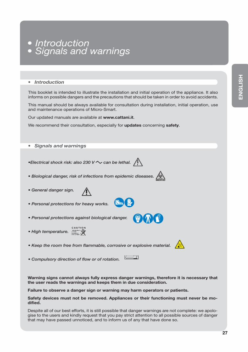
This booklet is intended to illustrate the installation and initial operation of the appliance. It also informs on possible dangers and the precautions that should be taken in order to avoid accidents.
This manual should be always available for consultation during installation, initial operation, use and maintenance operations of Micro-Smart.
Our updated manuals are available at www.cattani.it.
We recommend their consultation, especially for updates concerning safety.
• Introduction
•Electrical shock risk: also 230 V can be lethal.
• Biological danger, risk of infections from epidemic diseases.
• General danger sign.
• Personal protections for heavy works.
• Personal protections against biological danger.
• High temperature.
• Keep the room free from fl ammable, corrosive or explosive material.
• Compulsory direction of fl ow or of rotation.
• Signals and warnings
Warning signs cannot always fully express danger warnings, therefore it is necessary that the user reads the warnings and keeps them in due consideration.
Failure to observe a danger sign or warning may harm operators or patients.
Safety devices must not be removed. Appliances or their functioning must never be mo-difi ed.
Despite all of our best efforts, it is still possible that danger warnings are not complete: we apolo-gise to the users and kindly request that you pay strict attention to all possible sources of danger that may have passed unnoticed, and to inform us of any that have done so.
• Introduction • Signals and warnings

28
• Installation and initial operation
• Recommended precautions
Before unpacking the appliance, check the warning shock-watch on the carton. In the case of it being red or the car-ton being damaged, accept the material while reserving the right to examine the machine.
Unpack the appliance following the instructions shown on the package. The carton is recyclable. Dispose of it in com-pliance with regulations in force. Retain the plastic caps that cover all inlets and outlets of the unit, as they must be used if the machine needs to be moved or transported.
The machine installation must be carried out by a specia-list, equipped with the necessary tools. Install the applian-ce in a clean location, far from heat sources, humidity and dust. Micro-Smart can be installed outdoors (on a balcony, in veranda or gardens), provided that it is sheltered from rain, humidity, frost and direct sunshine.
For outdoor installation we recommend the use of our special designed box fi tted with double isolating roof, anti-freeze and ventilation systems (both fi tted with fi xed ther-mostat for automatic temperature control).
In the plant room temperature can range from a minimum of + 5 °C to +35 °C max.
Micro-Smart fi tted with box, for indoors or outdoors instal-lation, can be supplied with antifreeze device. In the case of the plant room requiring ventilation or air-conditioning, we suggest that you contact a thermo-technician for a tailored solution. The plant room must be closed to patients and extraneous people. If such a room is not available, machi-nes must be protected by a suitable cover, which must not be easy to remove. Use protections and danger warning boards to prevent accidental risk from electrical shocks, and/or the possibility (unlikely but not excludible) of fi re, explosion and contaminating air or liquid leakage. Only use boxes and covers, be them for indoors or outdoors, that are designed and produced by the manufacturer.
Keep the plant room free from fl ammable material. Make sure that there is no possibility for gas leakages. Do not connect damaged appliances to the mains power supply. Do not use extension leads, multiple plugs or sockets. Be-fore connecting the machine to the mains, ascertain that the feeding line is complying with the regulations C.E.I. 64-8 and that a thermal switch and a residual current ope-rated circuit-breaker (class A or B) (16A) according to the regulations EN 61008-1 are installed. Light coloured, woo-den, linoleum, rubber or marble fl oors can change colour or be marked if they are kept in contact with rubber vibration-proof devices (1). Therefore, it is necessary to use a rubber sheet or some other suitable material to isolate vibration-proof devices from the fl oor.
HANDLEWITH CARE
WARNINGWARNINGSHOCKWATCH R
RED INDICATES ROUGH HANDLINGIF RED, NOTE ON BILL OF LADINGINSPECTION MAY BE WARRANTED
MODEL L-55 (37g)
TOLL
FREE 1-80
0-527
-9497www.shockwatch.com
Min
ima
Maxim
a
30
20
10
0
10
20
30
40
50
50
40
30
20
10
0
10
20
30
1

EN
GL
ISH
20
2
6b
4
29
• Installation
Before connecting the aspirator to the piping of the centra-lized system, ascertain that aspiration piping is clean, as heavy debris can damage the appliance.
Connect the PVC light grey aspiration tube (3) (supplied with the machine) to the 30 mm Ø tube-holder (2) (“aspira-ted fl uid inlet”). The other end of the same tube should be connected to the aspiration piping (2b) coming from the surgeries.
The black heat resistant exhaust air pipe (4b), fi tted with a metal spiral, must be connected to the 30 mm Ø tube-holder (4) (“exhaust air outlet”). Connect the other end of the pipe to the antibacterial fi lter (5), passing preferably through a silencer (5a) supplied with the aspirator. The hot air coming from the antibacterial fi lter must be conveyed outside.
Connect the 18 mm Ø tube-holder (6, page 31) to the liquid drain pipe. In the version fi tted with Hydrocyclone the aspi-rator is draining liquids by gravity and therefore fl uids can-not be pumped upwards at all, and the pipe must be at the same level as, or lower than, the waste fl uid outlet. The 10 mm Ø tube-holder (8, page 30) (“emergency drain”) must be connected to the liquid drain pipe. In the version wi-thout Hydrocyclone the 11 mm Ø tube-holder (6b) must be connected to the liquid drain pipe. The piping connecting the machine to the aspiration and draining system should be fl exible to damper the small vibrations produced by the aspirator.
The aspiration piping should be run in the fl oor and at a point near the aspirator it should rise about 30 cm to reach the tu-be-holder (2) (draw. A and B, page 121).
If Micro-Smart is installed at a level lower than the surgeries, the aspiration piping must not enter the centrifugal separator perpendicularly. Rather, place a few me-tres of piping horizontally on the same level of the machine and then connect it to the centrifugal separator inlet which is at a higher level (using a fl exible pipe) (draw.B, page 121).
After the installation is completed, con-nect the power cable to the mains power supply according to the regulation EN 61008-1.
5
5a
4b4
2b
3
2
6b

• Starting, fi nal testing and users instructions
Finally, connect the low voltage line which connects the dental unit to the aspirator. Ascertain that the contacts on the dental unit are clean (volt-free contacts ).
Install and connect the aspirator. Select the ON position on the switch, which is illuminated once one of the dental units has started working. At this point aspiration will start.
To check if Micro-Smart is working correctly, it is advisable to carry out the dynamic tests (see draw. E, page 124) and to consult the Micro-Smart working diagram (draw. F, page 125).
Users must be instructed on the use and routine mainte-nance of the new, not used, and therefore not yet contami-nated, machines.
Demonstrate to users how to follow the Micro-Smart wor-king phases on the display, to interpret danger warnings and to carry out routine maintenance using Puli-Jet plus new (A) - (by means of Pulse-Cleaner) (B) - and Antifoa-ming Tablets (C) regularly.
The aspirating unit (9) (through pipe 10) creates vacuum inside the centrifugal separator (11). The fl uid coming from the dental units enters the centrifugal separator (11) from the pipe (2).
The centrifugal separator separates air from liquids: air is aspirated through to the suction motor, and then exhausted via the pipe (4), whereas liquids are drained to the sewage through the waste pipe connected to the tube-holder (6) in the version without Hydrocyclone and to the tube-holder (6b) in the version with Hydrocyclone.
The centrifugal separator (11) starts before the aspirating unit (9), this allows drainage of liquids that may have collec-ted inside the centrifugal separator before aspiration starts. Moreover, when the machine is switched off, a timer (adju-stable) keeps the motor running for min.10’’ - max. 120’’.
On request, Micro-Smart can be supplied with the amal-gam separator “Hydrocyclone ISO 5,5 l/min.” having its own separate manual.
B A
C
30
• Operation
• Amalgam Separator complying to the standard ISO 11143
11
8
9
10
2
6b
4

EN
GL
ISH
• Routine maintenance
Routine maintenance must be entrusted to specially in-structed surgery staff.
• We recommend that special attention be paid to all dan-ger signals, and that protective goggles, gloves and dispo-sable overalls for personal protection be used.
• Check for any possible alarm on the display. In case of alarms, contact the technician.
• At the end of every working day aspirate a solution of Pu-li-Jet plus new with anti-scale agent (A) disinfectant using the Pulse Cleaner (B).
• Clean the aspiration fi lters on the dental unit, collect the waste, especially amalgam, according to the regulations in force and place the Disinfectant Antifoam Tablets (C) in the dental unit fi lters.
• Disconnect the machine from the mains before any maintenance intervention.
• Clean the aspirator’s fi lter.
• Make sure that the aspirator ventilation is not obstructed.
• Keep the plant room free from anything not related to the machines, especially from fl ammable material. Make sure that there is no possibility for the formation of corrosive, fl ammable and explosive mixtures.
Daily (especially at the end of the working day and/or several times a day according to need)
Periodically, according to need
B A
C
31
ALLARME:TEMPERATURA ELEVATA
6

Extraordinary maintenance must be entrusted to a trained technician in possession of original spare parts.
• Pay special attention to danger signals. Use protective goggles, gloves and disposable overalls for personal pro-tection.
• Check that routine maintenance has been duly carried out and make sure that Magnolia products are used.
• Before any intervention carry out a series of washes with Fast&Steril 3 (D) disinfectant, then wait 15 minutes for a complete disinfectant action.
• Check maximum detected temperatures and all alarms. Intervene accordingly.
• Where routine maintenance is not carried out properly or unsuitable products are used, train the staff and inform the person in charge. Warranty ceases in case appliances are treated with products which are different from those re-commended.
• Check the aspirator noise level (see page 26).
• Remove dust from the control panel’s fan and heat sink using a blast of dry air not exceeding 2 bar pressure. By means of a 6 bar blast of air clean also the small holes on the frontal cover of the aspirating unit (15).
• Check the conditions of plastic hoses, in particular the hoses under pressure connecting the centrifugal separator (11) and the Hydrocyclone ISO. We suggest to replace the-se hoses every 18-24 months.
• Check the working conditions of the centrifugal separator (11) and re-circulation valve (14).
• Every time a component containing a rubber part (“O” ring, gasket or seal) is disassembled, replace the rubber part.
• Replace the motors bearings.
(*) Suggested maintenance intervention frequency is approximate. In
case of works causing a lot of dust or particularly intensive, increase
the frequency of interventions according to the needs.
Recommended every 12 months *
Recommended every 18-24 months
Recommended every 10,000/15,000 working hours
B D
32
• Extraordinary maintenance
ALLARME:TEMPERATURA ELEVATA
15
11
14

EN
GL
ISH
• Instructions to navigate Micro-Smart menus and to modify some parameters
Main menus
When Micro-Smart is switched on, the display shows the Cattani logo for 10 seconds, after which time the main menu appears.
Main Menu “A1”
This menu shows some parameters such as: suction mo-tor speed, suction activation time, temperature, presence/absence of the amalgam container and system software release.
Pressing the key takes you through
Control Menu “A2”
The display shows the number of times Micro-Smart has been switched on by means of the main switch (Power Cycles), the total hours Micro-Smart has had power sup-plied (Uptime), the number of times suction has been acti-vated (Work Cycles), the total running hours of the aspirator (Work Time), the working hours as regards to the cycles (HZ) used and the number of times the control panel coo-ling fan has been activated (Fan Cycles).
Right arrow
Events Menu “A3” This menu shows the last events or alarms that have occur-red to Micro-Smart. Events are indicated with a number; refer to the table at page 47 to identify them.
Control Menu “A2”
33
COUNTERS – ODOM . A2
POWER CYCLES 000000 Number of times the aspirator has been switched on
by means of the main switch.
UPTIME [ h] 000000 Total hours Micro-Smart has had power supplied
(motors switched-off).
WORK CYCLES 000000 Number of times the aspirator has been activated by
the dental unit.
WORK TIME [ h] 000000 Number of real running hours (motors running).
ASPIRATOR [ h] 000000 Working hours as regards to the cycles (HZ) used.
FAN CYCLES 000000 Number of times the control panel cooling fan has
been activated.
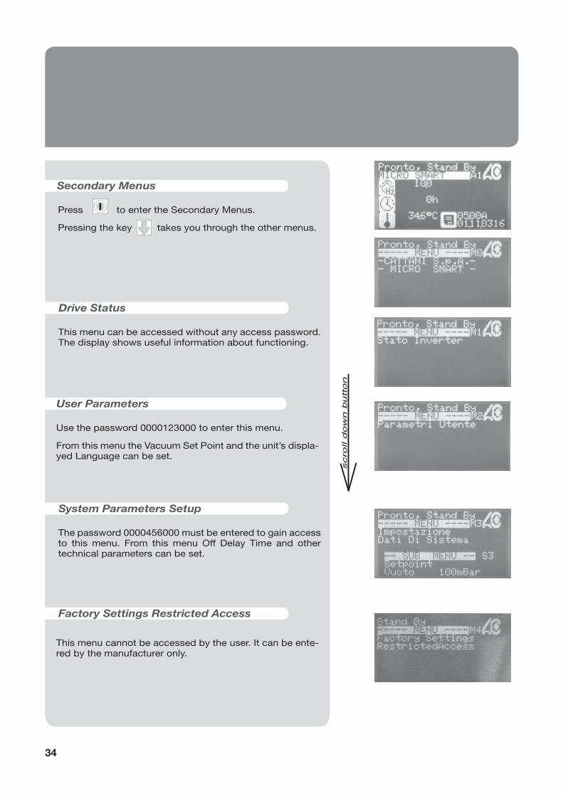
Press to enter the Secondary Menus.
Pressing the key takes you through the other menus.
Drive Status
This menu can be accessed without any access password. The display shows useful information about functioning.
User Parameters
Use the password 0000123000 to enter this menu.
From this menu the Vacuum Set Point and the unit’s displa-yed Language can be set.
System Parameters Setup
The password 0000456000 must be entered to gain access to this menu. From this menu Off Delay Time and other technical parameters can be set.
Factory Settings Restricted Access
Secondary Menus
I
This menu cannot be accessed by the user. It can be ente-red by the manufacturer only.
34

EN
GL
ISH
Entering Access Passwords
The Drive Status menu is the only menu that can be acces-sed without the use of an access password.
To enter the User Parameters and System Parameters Se-tup menus, you must fi rst enter an access password:
Access password for the User Parameters menu: 0000123000.
Access password for the System Parameters Setup menu: 0000456000.
From the CATTANI S.p.A. menu, press and then .
The Access Password screen Access Password 0000000000 should then be displayed.
Press the Enter Key which will make a cursor appear on the last zero to the right.
Press until the cursor is fl ashing on the 6th zero.
Press until number 1 appears.
Press to move to the next zero and then press
until number 2 appears.
Press to move to the next zero and then press until number 3 appears.
Press the Enter Key to confi rm the password. The cursor will disappear.
Press to return to the Cattani S.p.A. menu.
It is now possible to modify the parameters of the User Parameters menu.
Repeat the same process to enter the password 0000456000 to gain access to the System Parameters Se-tup menu.
I
I
35

This menu can be accessed without any access password. It displays various technical parameters regarding the real-time working conditions of Micro-Smart. Listed below is the more commonly required information.
Drive Status Menu
Blower Output Frequency (max. setting: 120 Hz)
Blower Output Voltage (max. setting: 220V)
Blower Overall Current (max. setting: 4,3 A)
Pump (Centrifuge) Output Frequency (fi xed setting: 75 Hz)
Pump (Centrifuge) Output Voltage (max. setting: 220V)
Pump (Centrifuge) Overall Bus Current (max. setting: 3,2 A)
36

EN
GL
ISH
System Temperature
Maximum Detected Temperature (+60 °C: Alarm and Stop of the aspirator, it can be reset)
Maximum Detected Temperature (+60 °C: Temperature me-mory, it cannot be reset)
Power Bus Voltage (Max. 390V)
Max. Detected Power Bus Voltage (Max. 390V)
Power Bus Ripple
Vacuum Set Point (max. setting: 210 mbar)
37

To access this menu you are required to enter the access password 0000123000 (see instructions on page 35).
User Parameters menu
Vacuum Set Point
This is the fi gure to which the unit will limit the vacuum.
Press the Enter Key to make the cursor appear.
The fi gure can be changed using the arrow keys .
Press the Enter Key again to confi rm.
Language
It is possible to choose either English (1) or Italian (0), French (2), German (3) for the displayed language.
Press the Enter Key to enable the cursor and use the
arrow keys to select 0 or 1 or 2 or 3.
Press the Enter Key again to confi rm the change.
Generated Code
This code is generated by Cattani S.p.A. Each unit is allo-cated a unique code. At present this code is not used.
Activation Code
At present this code is not used.
I
I
I
I
Run mode (it describes the machine’s running mode)
38
EN
GL
ISH
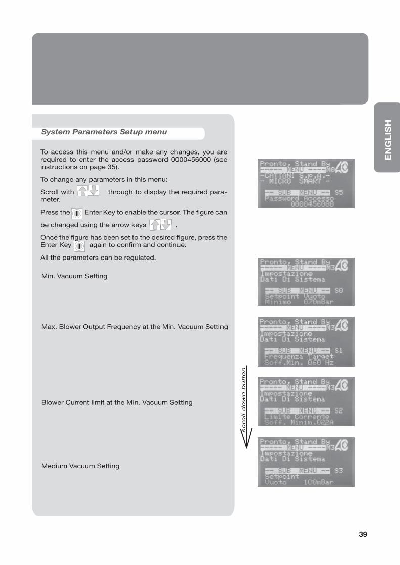
System Parameters Setup menu
To access this menu and/or make any changes, you are required to enter the access password 0000456000 (see instructions on page 35).
To change any parameters in this menu:
Scroll with through to display the required para-meter.
Press the Enter Key to enable the cursor. The fi gure can
be changed using the arrow keys .
Once the fi gure has been set to the desired fi gure, press the Enter Key again to confi rm and continue.
All the parameters can be regulated.
Min. Vacuum Setting
Max. Blower Output Frequency at the Min. Vacuum Setting
Blower Current limit at the Min. Vacuum Setting
Medium Vacuum Setting
I
I
39
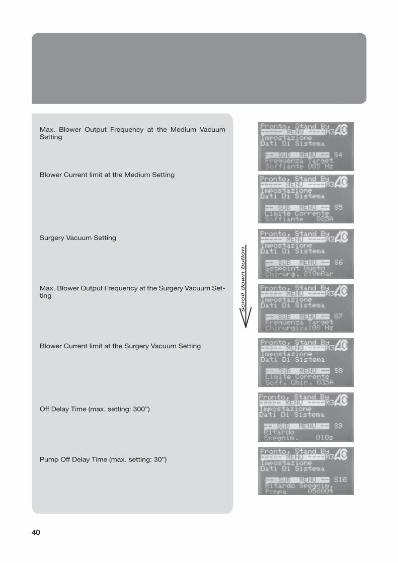
Max. Blower Output Frequency at the Medium Vacuum Setting
Blower Current limit at the Medium Setting
Surgery Vacuum Setting
Max. Blower Output Frequency at the Surgery Vacuum Set-ting
Blower Current limit at the Surgery Vacuum Setting
Off Delay Time (max. setting: 300”)
Pump Off Delay Time (max. setting: 30”)
40

EN
GL
ISH
Blower Off Delay Time (max. setting: 300”)
Running Options
This enables or disables the amalgam level sensor.
Set to 0: without amalgam separator
Set to 2: with amalgam separator
Drive Commands
Factory use only.
Modbus address
This menu is not currently used.
Network address
Specify the network address of the Micro SMART for Zig-Bee visualization.
Zig-Bee Minimum Channel
Select the minimum channel on which the Micro SMART shall communicate.
Zig-Bee Maximum Channel
Select the maximum channel on which the Micro SMART shall communicate.
41

42
Set the network address of the machine. (min. 100)(max. 110)
• Instructions for Zig-bee communication settings (wireless)
Install the ‘Smart System Monitor’ program supplied by Cattani Spa.
Insert the Zig-Bee communication key (ETRX2USB) into a USB connection on the clinic computer and launch the visualization program.
Once the program has been launched the main company screen will be displayed for around 10 seconds, after which time the main menu will appear.
Click on the ‘SERVICE’ menu in order to enter the device-search page.

EN
GL
ISH
43
Click on the ‘search available devices’ tab. The program will initiate a search, which can take several seconds. Once the search is completed, the program will display the va-rious available units and their corresponding generated code. NB: It may be necessary to repeat this process several times.
After having found the available devices, return to the home page to view parameters.
Select which Micro SMART you wish to view, by selecting it through the drop-down menu.
It is now possible to view the operating parameters.

44
By clicking on the ‘SERVICE’ tab you can access three different menus, one of which is open, and the other two restricted by a passwords.
To enter the ‘USER PARAMETERS’ menu enter the password 123000 and press ‘OK’.
Through this menu you can select a different language and set the desired vacuum level.
To enter the ‘SYSTEM PARAMETERS SETUP’ menu enter the password 456000 and press ‘OK’.

EN
GL
ISH
45
Through this technical menu you can view and modify all the parameters.
In case of malfunction an alarm will be shown on the screen and an e-mail sent to the contact entered (as per above point).
The ‘INVERTER STATUS’ menu does not require an access password. This menu displays the functional parameters of the machine while it is in operation.
From the main menu, click on the ‘E-MAIL’ tab to enter the details of the technician or doctor to whom alarm alerts should be sent.

46
The full history of all alarms registered during the entire period of operation can be viewed through the ‘EVENTS LOG’ tab.
The operation cycles are recorded, and can be viewed by clicking on the “ODO COUNTERS’ tab.
Any alarms generated through the day are displayed with an error code and description in the ‘ALERTS’ tab.

EN
GL
ISHAC100
Alarm code
DESCRIPTION SOLUTION
0 Microcontroller memory alarm Contact the technician
32 Microcontroller memory alarm Contact the technician
33 Short-circuit in one of the two motors Identify where the short-circuit is coming from
and eliminate it
34 Short-circuit before the motors’ starting Contact the technician (the PC-Board is likely to
be damaged)
35 Condensers have not been charged Contact the technician (replace the PC-Board)
36 Overtemperature (temperature has exceeded
the max. allowed limit)
Ventilate the plant room
Check operation of the cooling fan
37 Blower overcurrent (the blower has exceeded
the current limit)
Check the operation of the blower (seized or
excessive friction)
39 Condensers overvoltage (the condensers have
exceeded the max.voltage limit)
Check the mains voltage (max. 260V)
40 Centrifuge short-circuit Eliminate the short-circuit
41 PC-Board short-circuit on the centrifuge output Replace the PC-Board
42 Centrifuge instant overcurrent (the centrifuge
has exceeded the current limit)
Eliminate siphons in the piping or check the
centrifuge operation (seized or excessive friction)
43 Centrifuge time delayed overcurrent
(the centrifuge has exceeded the current limit)
Eliminate siphons in the piping or check the
centrifuge operation (seized or excessive friction)
45 Amalgam level sensor disconnected Connect the amalgam level sensor
46 Amalgam level > 95% Replace the amalgam container as soon as
possible
47 Amalgam level > 100% Replace the amalgam container
48 The vacuum detecting tube is disconnected Connect the vacuum detecting tube to the
centrifuge
49 Thermal switch switched-off Restore the temperature in the machine room
• Description of alarms
47

• Packed appliances can be transported and stored at a temperature ranging from -10 °C to + 60 °C.
• Packages must be kept away from water and splashing and cannot tolerate humidity >70%.
• Packages with the same weight can be stored in piles of three only.
• Transport and storage
• Transport of second-hand appliances
• Before packing, we suggest to cleanse and disinfect the aspirator with Fast & Steril 3 (refer to the paragraphs “Signals and warnings” and “Routine maintenance“).
• Drain all tubes and ports (including those that convey fl uids from inside machine) and possible residual fl uids (including disinfectant), which can damage the control panel. Remove the amalgam collection canister, add the disinfectant, place and then lock the hermetically sealed lid on the canister. Once the suction unit is dry –both externally and internally- close all of the inlets and outlets with the purpose-made caps, fi t a new (and empty) amalgam collection canister to the unit, and wrap both the suction unit and control panel separately in plastic, in order to ensure that these items are waterproof.
• Place the machine into a polyethylene bag, seal and pack it in 3-layer corrugated board.
• Important notices• Transport and storage • Transport of second-hand appliances
• Important notices
• Appliances are guaranteed for one year from the date of sale, provided that the warranty slip is returned to the manufacturer with date of sale, retailer’s and customer’s name.
• Warranty and manufacturer’s liability cease in case appliances are treated with products which are unsuitable or different from those recommended by the manufacturer and also in case appliances are improperly used or tampered with operations of any kind carried out by people who are not authorized by the manufacturer.
• The manufacturer, concessionaires, agents and authorized technicians are at customers’ disposal for advice and assistance and to supply literature, spare parts and anything useful.
• The manufacturer reserves the right to modify the products for improvements, for technical, normative and functional reasons or for problems due to the availability of products or semi-fi nished products, without prior notice.
• Our updated manuals are available at www.cattani.it. We recommend they are consulted especially for updates concerning safety.
• Micro-Smart is a EEE device, therefore it is subject to the WEEE (Waste of Electrical and Electronic Equipment) regulations.
48

121
Min
500
mm
Min 1000 mm
Max
300
mm
Max
300
mm
all’aspiratoreto the aspirator
all’aspiratoreto the aspirator
MONTAGGIO SOTTOSTANTE
INSTALLATION ON A LOWER FLOOR THAN THE ONE OF THE DENTAL UNITS
Fig. BDraw.B
MONTAGGIO AL PIANO
INSTALLATION ON THE SAME FLOOR OF THE DENTAL UNITS
Fig. ADraw. A
• SCHEMA DI MONTAGGIO Micro-Smart• Micro-Smart INSTALLATION LAYOUT

122
R
S
T
T
S
R
1234567
DI SPLAY LI NE
TI P SU PPORT
ALARM CONT ACT
BLOWER CENTRIFUGAL SEPARATOR
• COLLEGAMENTI CIRCUITO INVERTER AC100• INVERTER AC100 CONNECTIONS
Fig. C
Draw. C

123
MAI
NFI
LTER
AMAL
GAM
ELEC
TRON
ICCO
NTR
OL
DIS
PLAY
2X
T16
A6
X32
FUSE
CEN
TRIF
UGA
SOFF
IANT
E
1 2
3 4
MAI
NSW
ITC
H
FAN
Fig. D
Draw. D
124
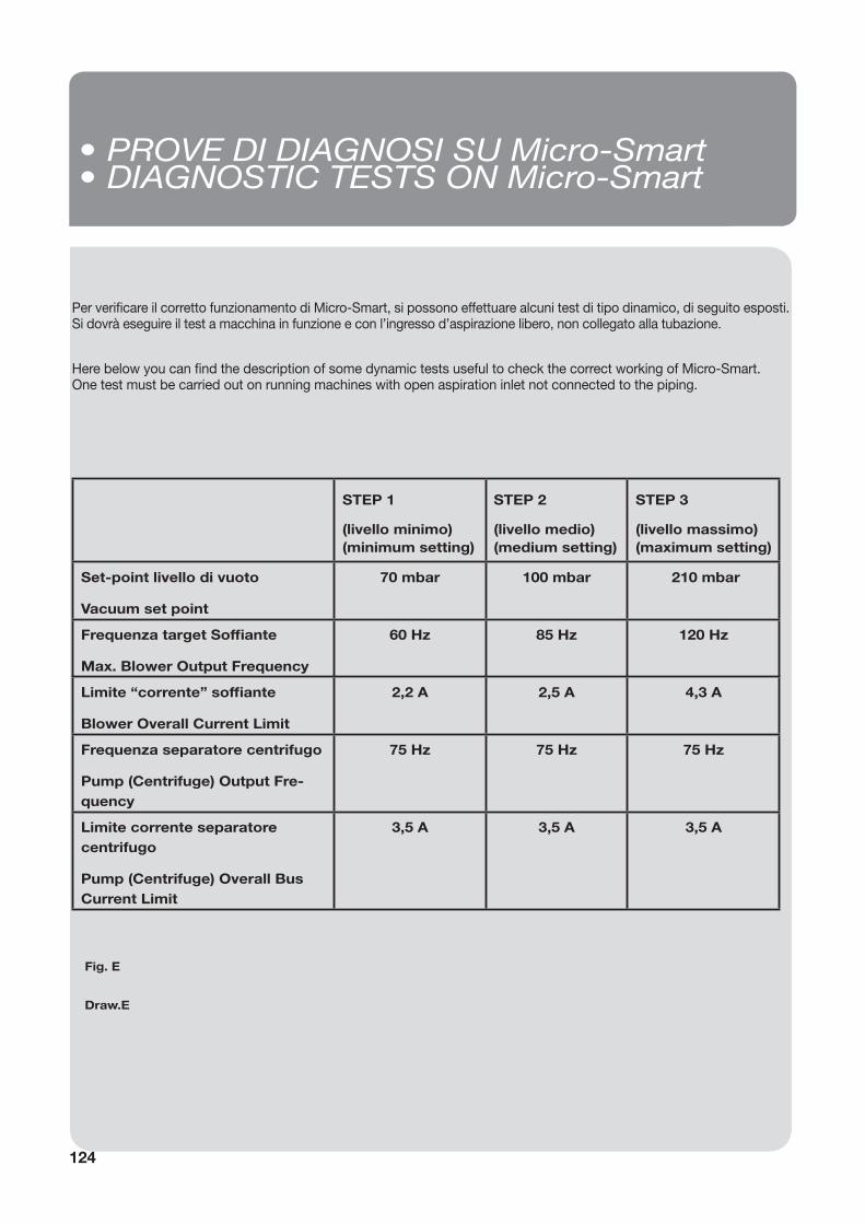
Per verifi care il corretto funzionamento di Micro-Smart, si possono effettuare alcuni test di tipo dinamico, di seguito esposti.Si dovrà eseguire il test a macchina in funzione e con l’ingresso d’aspirazione libero, non collegato alla tubazione.
Here below you can fi nd the description of some dynamic tests useful to check the correct working of Micro-Smart.One test must be carried out on running machines with open aspiration inlet not connected to the piping.
STEP 1
(livello minimo) (minimum setting)
STEP 2
(livello medio) (medium setting)
STEP 3
(livello massimo) (maximum setting)
Set-point livello di vuoto
Vacuum set point
70 mbar 100 mbar 210 mbar
Frequenza target Soffi ante
Max. Blower Output Frequency
60 Hz 85 Hz 120 Hz
Limite “corrente” soffi ante
Blower Overall Current Limit
2,2 A 2,5 A 4,3 A
Frequenza separatore centrifugo
Pump (Centrifuge) Output Fre-quency
75 Hz 75 Hz 75 Hz
Limite corrente separatore centrifugo
Pump (Centrifuge) Overall Bus Current Limit
3,5 A 3,5 A 3,5 A
• PROVE DI DIAGNOSI SU Micro-Smart• DIAGNOSTIC TESTS ON Micro-Smart
Fig. E
Draw.E
125
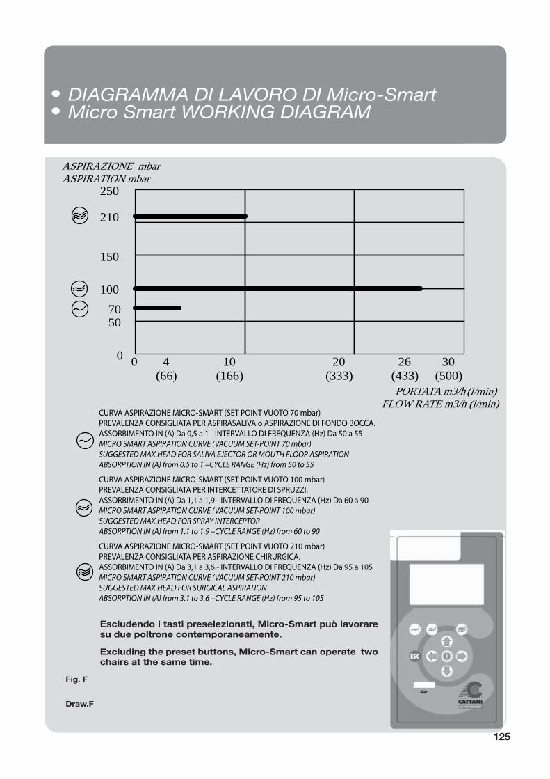
• DIAGRAMMA DI LAVORO DI Micro-Smart• Micro Smart WORKING DIAGRAM
Fig. F
Draw.F
70
4(66)
26(433)
250
210
ASPIRAZIONE mbar ASPIRATION mbar
100
0
50
150
0 10(166)
20(333)
30(500)
PORTATA m3/h (l/min)FLOW RATE m3/h (l/min)
CURVA ASPIRAZIONE MICRO-SMART (SET POINT VUOTO 70 mbar)PREVALENZA CONSIGLIATA PER ASPIRASALIVA o ASPIRAZIONE DI FONDO BOCCA.ASSORBIMENTO IN (A) Da 0,5 a 1 - INTERVALLO DI FREQUENZA (Hz) Da 50 a 55MICRO SMART ASPIRATION CURVE (VACUUM SET-POINT 70 mbar)SUGGESTED MAX.HEAD FOR SALIVA EJECTOR OR MOUTH FLOOR ASPIRATIONABSORPTION IN (A) from 0.5 to 1 –CYCLE RANGE (Hz) from 50 to 55
CURVA ASPIRAZIONE MICRO-SMART (SET POINT VUOTO 100 mbar)PREVALENZA CONSIGLIATA PER INTERCETTATORE DI SPRUZZI.ASSORBIMENTO IN (A) Da 1,1 a 1,9 - INTERVALLO DI FREQUENZA (Hz) Da 60 a 90 MICRO SMART ASPIRATION CURVE (VACUUM SET-POINT 100 mbar)SUGGESTED MAX.HEAD FOR SPRAY INTERCEPTORABSORPTION IN (A) from 1.1 to 1.9 –CYCLE RANGE (Hz) from 60 to 90
CURVA ASPIRAZIONE MICRO-SMART (SET POINT VUOTO 210 mbar)PREVALENZA CONSIGLIATA PER ASPIRAZIONE CHIRURGICA.ASSORBIMENTO IN (A) Da 3,1 a 3,6 - INTERVALLO DI FREQUENZA (Hz) Da 95 a 105 MICRO SMART ASPIRATION CURVE (VACUUM SET-POINT 210 mbar)SUGGESTED MAX.HEAD FOR SURGICAL ASPIRATIONABSORPTION IN (A) from 3.1 to 3.6 –CYCLE RANGE (Hz) from 95 to 105
Escludendo i tasti preselezionati, Micro-Smart può lavorare su due poltrone contemporaneamente.
Excluding the preset buttons, Micro-Smart can operate two chairs at the same time.
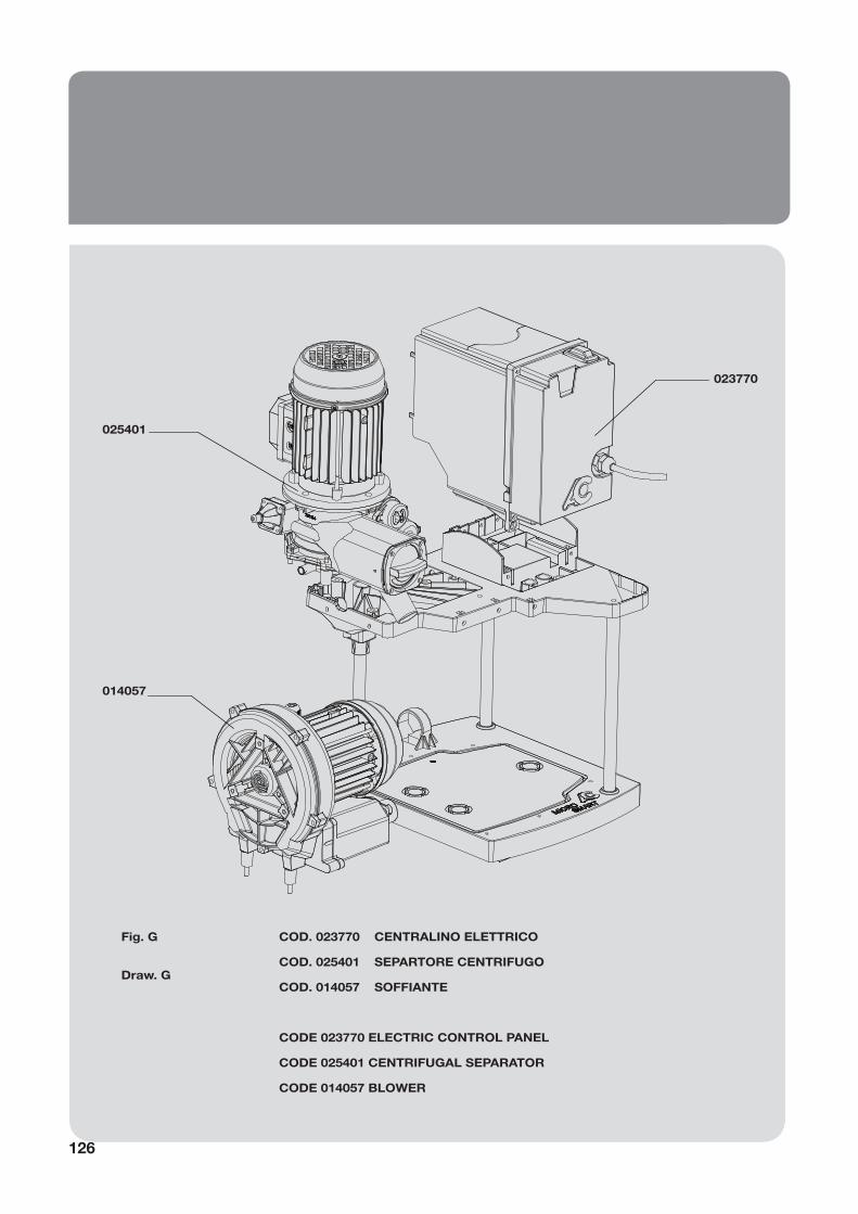
126
COD. 023770 CENTRALINO ELETTRICO
COD. 025401 SEPARTORE CENTRIFUGO
COD. 014057 SOFFIANTE
CODE 023770 ELECTRIC CONTROL PANEL
CODE 025401 CENTRIFUGAL SEPARATOR
CODE 014057 BLOWER
023770
025401
014057
Fig. G
Draw. G

127
380
Scarico liquidiLiquids outlet
AspirazioneAspiration
Aria espulsaExhausted air outlet
600
350
Fig. H
Draw.H

Ed
. N
ovem
ber
20
14
6/A Via Natta. 43122 Parma, Italy
10’21’48” EST - 44’50’46” NORD
Ph. +39.0521.607604
Fax +39.0521.607628 (Sales Dept.)
Fax +39.0521.607855 (Purchasing Dept.)
Fax +39.0521.399966 (Accounting Dept.)
www.cattani.it - e-mail: [email protected]
Company with Quality System Certifi ed according to
UNI EN ISO 9001:2008 - UNI EN ISO 13485:2012
WE RESEARCH: this lets us apply the latest technology in all of our products and solutions.WE INCREASE PERFORMANCE: electronic and information technology allow us to increase the performance and reliability of our products.
WE REDUCE COSTS: less maintenance and energy costs mean on a cost-bene t analysis we are always the most economical.
WE REDUCE ENVIRONMENTAL IMPACT: we save 50% of primary materials, and allow you to save between 30% and 50% of electrical consumption.
WpWa
WWb
Wmc
HOW CAN WE DO WE LEAD IN OUR FIELD,
YET WE COST LESS THAN THE ALTERNATIVES?
THIS IS HOW: