Embed Size (px)
Citation preview

Release 1.2, March 2002Model 58210, 58220
58610, 58620
ManualLAN-Modem
W&T
W&T
© 03/2002 by Wiesemann und Theis GmbHSubject to error and alteration:
Since it is posssible that we make mistakes, you mustn’t useany of our statements without verification. Please, inform usof any error or misunderstanding you come about, so we canidentify and eliminate it as soon as possible.
Carry out your work on or with W&T products only to theextent that they are described here and after you havecompletely read and understood the manual or guide. We arenot liable for unauthorized repairs or tampering. When indoubt, check first with us or with your dealer.

W&T
IntroductionThe LAN-Modem permits devices that require dial-upmodems for communicating to use the Intranet orInternet instead of the telephone system. On a serialinterface, the LAN-Modem behaves in a way this iscompatible with standard modems for the telephonesystem; the only difference is that the dial-up number isreplaced by an IP address.
Modem
Intranet /Internet
“ATDT <Tel. No.>”
RS232
RS232
RS232
RS232
before:
LAN Modem
LAN Modem
RS232
“RING”
now:
serialdevice
serialdevice
serialdeviceRS232
Modem
Modem
ModemRS232
“RING”
serialdevice
serialdevice
serialdevice
“ATDT <IP. No.>”RS232

4
W&T
Contents
1 Quick Installation 71.1 Installation in flow chart form 8
2 Connections and Displays 92.1 Ethernet connection 102.2 The RS232 connection 122.3 Supply voltage 132.3.1 5V supply voltage (58210, 58220) 132.3.2 12–24V supply voltage (58611, 58620) 132.4 LED displays 14
3 TCP/IP Configuration 153.1 Assigning the IP using the „ARP“ command 163.2 Assigning the IP through the serial port 183.2.1 Serially deactivating the DHCP-/BOOTP-Client 193.3 Assigning the IP using an RARP server 203.4 Assigning the IP using DHCP-/BOOTP protocol 213.4.1 Deactivating the DHCP-/BOOTP protocol 223.5 Configuring the subnet mask and gateway 24
4 Modem Operation 274.1 Serial transmission parameters 284.2 Command syntax 294.3 Command and data mode 304.4 All AT commands 314.4.1 A (ATA) 324.4.2 D (ATD[IP address]) 334.4.3 E (ATE[0|1]) 364.4.4 H (ATH) 364.4.5 In (ATI[0–8]) 364.4.6 O (ATO) 374.4.7 Q (ATQ0|1) 374.4.8 Sn? (ATS[0-40]?) 374.4.9 Sn=x (AT[0–40]=[0–255]) 384.4.10 Vn (ATV[0|1]) 394.4.11 Zn (ATZ[0|1]) 404.4.12 &C (AT&C[0|1]) 404.4.13 &D (AT&C[0|1|2|3]) 41

5
W&T
Subject to error and alteration
4.4.14 &Fn (AT&F[0|1]) 414.4.15 &K (AT&K[0|3|4|5|6]) 424.4.16 &Sn (AT&S[0|1]) 434.4.17 &Vn (AT&V[0|1|2]) 434.4.18 &Wn(AT&W[0|1]) 444.4.19 &Yn (AT&Y[0|1]) 444.4.20 &Zn=x (AT&Z[0|1|2|3]=[IP address]) 454.4.21 %Bn (AT%B[2-8]) 454.4.22 %Dn (AT%D[7|8]) 464.4.23 %Pn (AT%P[0|1|2]) 464.4.24 %Sn (AT%S[1|2]) 474.4.25 %Nn (AT%N[0|1]) 474.4.26 ** (AT**) 48
5 Firmware-Update 495.1 Where do I get the latest firmware? 505.2 Serial update of the AT command interpreter 515.3 Network update of the AT command interpreter 52Example with Telnet client under Windows 95/98/NT 525.4 Updating the TCP/IP-Stack 54
Appendix 57Reading/Sending Configuration Profiles 58The Modem Protocol on the TCP Level 59Virtual Modem Ports under Windows NT/2000/XP 60Technical Data 61Declaration of conformity 62

6
W&T
7
W&T
Subject to error and alteration
1 Quick Installation
■ LAN-Modem installation in flow chart form

8
W&T Schnellinstallation
1.1 Installation in flow chart form
The following diagram shows the essential installationsteps for any LAN-Modem installation.
LAN-Modem
Intranet /Internet
Ethern
et
LAN-Modem (x)
Standortwahl
Anschluß derHardware
Verbindung über Router /
Bridge ?
nein
ja
Einstellung derIP-Adresse
ENDE
Modemanwendungbzw. ser. Gerät:Ersatz der Tele-
fonnummer durchIP-Adresse
Einstellung desGateways
Einstellung derSubnet-Mask
1.) Telnet-Session auf den Konfigura-tionsport des LAN-Modem:
Telnet [LAN-Modem] 1111
2.) Menüpfad Subnet-Mask-Konfiguration :-> 2 SETUP System-> 2 Setup TCP/IP-> 2 Subnet Mask -> [neue Subnet Mask]
3.) Menüpfad Gateway-Konfiguration:-> 2 SETUP System-> 2 Setup TCP/IP-> 3 Gateway -> [Router-IP-Adresse]
- Anschluß der Spannungsversorgung- Netzwerk-Anschluß über Patchkabel- Verbindung der seriellen Schnittstellen
1.) Statischer Eintrag in ARP-Cache einesRechners im selben Subnet:
arp -s [IP-Adresse] [Ether.-Adr. LANModem]
2.) ping [IP-Adresse]

9
W&T
Subject to error and alteration
2 Connections and Displays
■ Pin Assignments
■ Supply Voltage
■ LED displays
10
W&T Connections and Displays
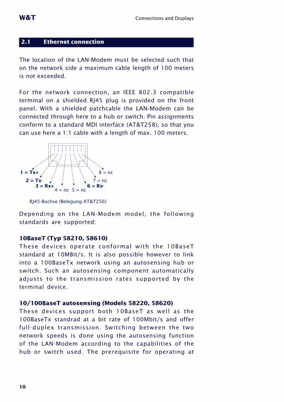
2.1 Ethernet connection
The location of the LAN-Modem must be selected such thaton the network side a maximum cable length of 100 metersis not exceeded.
For the network connection, an IEEE 802.3 compatibleterminal on a shielded RJ45 plug is provided on the frontpanel. With a shielded patchcable the LAN-Modem can beconnected through here to a hub or switch. Pin assignmentsconform to a standard MDI interface (AT&T258), so that youcan use here a 1:1 cable with a length of max. 100 meters.
1 = Tx+
2 = Tx-3 = Rx+
4 = nc 5 = nc6 = Rx-
7 = nc
8 = nc
RJ45-Buchse (Belegung AT&T256)
Depending on the LAN-Modem model, the followingstandards are supported:
10BaseT (Typ 58210, 58610)These devices operate conformal with the 10BaseTstandard at 10MBit/s. It is also possible however to linkinto a 100BaseTx network using an autosensing hub orswitch. Such an autosensing component automaticallyadjusts to the transmission rates supported by theterminal device.
10/100BaseT autosensing (Models 58220, 58620)These devices support both 10BaseT as well as the100BaseTx standrad at a bit rate of 100Mbit/s and offerfull-duplex transmission. Switching between the twonetwork speeds is done using the autosensing functionof the LAN-Modem according to the capabilities of thehub or switch used. The prerequisite for operating at
11
W&T Connections and Displays
Subject to error and alteration
100MBit/s is appropriate cabling (Cat 5/ISO Class D orbetter).
The current link status is indicated by the Error LED onthe front panel: If it blinks at 1-2 second intervals, thereis no connection to the hub, or the connection is faulty.
12
W&T Connections and Displays
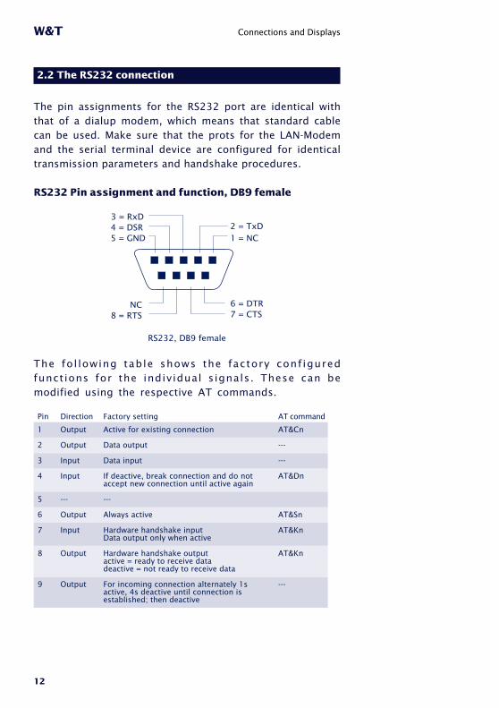
2.2 The RS232 connection
The pin assignments for the RS232 port are identical withthat of a dialup modem, which means that standard cablecan be used. Make sure that the prots for the LAN-Modemand the serial terminal device are configured for identicaltransmission parameters and handshake procedures.
RS232 Pin assignment and function, DB9 female
RS232, DB9 female
1 = NC2 = TxD
3 = RxD
5 = GND4 = DSR
8 = RTSNC
7 = CTS6 = DTR
The fo l lowing table shows the factory conf iguredfunctions for the individual s ignals. These can bemodified using the respective AT commands.
Factory setting
Active for existing connection
Data output
Data input
If deactive, break connection and do notaccept new connection until active again
---
Always active
Hardware handshake inputData output only when active
Hardware handshake outputactive = ready to receive datadeactive = not ready to receive data
For incoming connection alternately 1sactive, 4s deactive until connection isestablished; then deactive
Direction
Output
Output
Input
Input
---
Output
Input
Output
Output
Pin
1
2
3
4
5
6
7
8
9
AT command
AT&Cn
---
---
AT&Dn
AT&Sn
AT&Kn
AT&Kn
---

13
W&T Connections and Displays
Subject to error and alteration
2.3 Supply voltage
Depending on the hardware version, the LAN-Modems aresupplied either with a regulated +5V or with an AC/DCvoltage of between 12V and 24V.
2.3.1 5V supply voltage (58210, 58220)
The supply voltage for models 58210 and 58220 isbrought in through the power terminal located on theunderside of the housing. The supply voltage is 5V +/-5%. The current consumption of the various models canbe found in the technical appendix.
2.3.2 12–24V supply voltage (58611, 58620)
The supply voltage for models 58610 and 58620 can alsobe brought in through the power terminal for jack plugslocated on the housing underside. Both DC voltage of anypolarity as well as AC voltage may be used. Polarityversal protection results in the following maximum andminimum values for the supply voltage:
� AC: 9Veff (-5%) – 24Veff (+5%)� DC: 12V (-5%) – 34V (+5%)
The current consumption of the various models can be foundin the technical appendix.

14
W&T Connections and Displays
2.4 LED displays
Status and error information is indicated by the LAN-Modemusing three LEDs having various blink codes.
• Power-LEDIndicates the presence of supply voltage. If the LED isno t f u l l on , p l ease check you r power supp l yconnections.
• Status-LEDFlashes when there is network activity with the LAN-Modem. Periodic flashing indicates that the port hasa connection to another station.
• Error-LEDThe error LED uses various blink codes to indicateerror states on the device or serial port:1 xflashing = Check network connection
The LAN-Modem is not receiving a link pulse froma hub. Check the cable and hub.
2 x fhashing = Check serial basic configurationUse the Telnet configuration to check the basicsettings of the LAN-Modem for Port 0:SETUP Port 0 (serial) r UART Setup r Baud = 57600
SETUP Port 0 (serial) r UART Setup r Parity = NONE
SETUP Port 0 (serial) r UART Setup r Data Bits = 8
3 x flashing = Check serial basic configurationUse the Telnet configuration to check the basicsettings of the LAN-Modem for Port 0:SETUP Port 0 (serial) r UART Setup r Handshake = HARDWARE
All LEDs on = Self-test errorThe self-test performed after each start or reset ofthe LAN-Modem could not be correctly finished duefor example to an incomplete update of thefirmware. In this state the LAN-Modem is no longeroperational. Please return the unit for repair.
iFor additionalinformatio on thesettings, please referto section 4 „ModemOperation“
15
W&T
Subject to error and alteration
3 TCP/IP Configuration
Following the hardware installation, this section describes the logical
integration of the LAN-Modem into the TCP/IP network.
■ Assigning the IP address
■ Setting the Subnet-Mask and Gateway
You can obtain all the parameters from the system administrator of
your network. In contrast to the IP address, which is always required,
you may skip the setting of the subnet mask and gateway if the
communications partner for the LAN-Modem is located in the same
network.
16
W&T TCP/IP Configuration
3.1 Assigning the IP using the „ARP“ command
1This method can only be used if the LAN-Modem doesnot yet have an IP address, i.e. the current entry is
0.0.0.0. To change an IP address, use one of the othermethods described in this section or use the configurationmenu via TELNET.
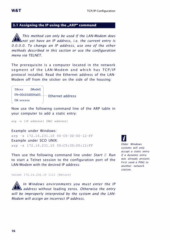
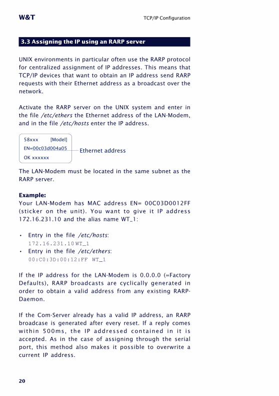
The prerequisite is a computer located in the networksegment of the LAN-Modem and which has TCP/IPprotocol installed. Read the Ethernet address of the LAN-Modem off from the sticker on the side of the housing:
58xxx [Model]
EN=00c03d004a05
OK xxxxxxEthernet address
Now use the following command line of the ARP table inyour computer to add a static entry:
arp -s [IP address] [MAC address]
Example under Windows:arp -s 172.16.231.10 00-C0-3D-00-12-FF
Example under SCO UNIX:arp -s 172.16.231.10 00:C0:3D:00:12:FF
Then use the following command line under Start → Runto start a Telnet session to the configuration port of theLAN-Modem with the desired IP address:
telnet 172.16.232.10 1111 [Return]
1 In Windows environments you must enter the IPaddress without leading zeros. Otherwise the entry
will be improperly interpreted by the system and the LAN-Modem will assign an incorrect IP address.
iOlder Windowssystems will onlyaccept a static entryif a dynamic entrywas already present.First send a PING toanother networkstation.
17
W&T TCP/IP Configuration
Subject to error and alteration
iEvery IP address mustbe used only once inthe network.
The LAN-Modem accepts the IP address of the first networkpacket sent to it as its own and saves it in non-volatile RAM.Only now is the Telnet connection established and theconfiguration menu shown in the Telnet window. Now youmay sete the subnet mask and gateway (see section 3.5Configuring the subnet mask and gateway).
18
W&T TCP/IP Configuration
3.2 Assigning the IP through the serial port
After the LAN-Modem has been reset, a time window ofapprox. 1-2 seconds is provided during which you canassign a new IP address by entering at least three „x“.
1 In contrast to the previously described using ARP, this serial path works regardless of whether theLAN-Modem already has an IP address or not. Theprocedure can be repeated as often as desired. Thismethod is therefore recommended if you do not know theIP address or have forgotten it.
First connect the serial port of the LAN-Modem to acomputer. For a standard PC or a laptop, you will requirea 1:1 modem cable (see section 2.2 The RS232 connection).
The serial transmission parameters of the terminal programused are configured for 9600 Baud, no Parity, 8 bits, 1 stopbit, no handshake. Interrupt the supply voltage to the LAN-Modem to perform a reset. If the green Status LED comes on,enter the letter „x“ at least three times on the terminal untilthe LAN-Modem has returned the prompt „IPno.+<Enter>:“.
Use the usual format (xxx.xxx.xxx.xxx) to enter the IPaddress and finish your entry by pressing <Enter>. If theentry was accepted, this is acknowledged with theassigned IP address. Otherwise a „FAIL“ message isreturned with the last current IP address.
All other settings such as the gateway address, subnetmask, etc. are made using the Telnet configuration menu(see section 3.5 Configuring the subnet mask and gateway).
19
W&T TCP/IP Configuration
Subject to error and alteration
3.2.1 Serially deactivating the DHCP-/BOOTP-Client
The DHCP-/BOOTP function of the LAN-Modem can be turnedoff when serially assigning the IP address. We recommenddoing this in all cases where it is not absolutely necessary touse DHCP/BOOTP to assign the IP.
To deactivate the DHCP-/BOOTP client, attach the option „-0“directly after the IP address (no spaces) and confirm yourentry with <Enter>.
Example:
xxx -> Com-Server
IP no.+<ENTER>: <- Com-Server
172.17.231.99-0 -> Com-Server
172.17.231.99 <- Com-Server
You can always reactivate the function later using theTelnet configuration under SETUP System r SETUP TCP/IP rBOOTP Client.
20
W&T TCP/IP Configuration
3.3 Assigning the IP using an RARP server
UNIX environments in particular often use the RARP protocolfor centralized assignment of IP addresses. This means thatTCP/IP devices that want to obtain an IP address send RARPrequests with their Ethernet address as a broadcast over thenetwork.
Activate the RARP server on the UNIX system and enter inthe file /etc/ethers the Ethernet address of the LAN-Modem,and in the file /etc/hosts enter the IP address.
58xxx [Model]
EN=00c03d004a05
OK xxxxxxEthernet address
The LAN-Modem must be located in the same subnet as theRARP server.
Example:Your LAN-Modem has MAC address EN= 00C03D0012FF(sticker on the unit). You want to give it IP address172.16.231.10 and the alias name WT_1:
• Entry in the file /etc/hosts:172.16.231.10 WT_1
• Entry in the file /etc/ethers:00:C0:3D:00:12:FF WT_1
If the IP address for the LAN-Modem is 0.0.0.0 (=FactoryDefaults), RARP broadcasts are cyclically generated inorder to obtain a valid address from any existing RARP-Daemon.
If the Com-Server already has a valid IP address, an RARPbroadcase is generated after every reset. If a reply comeswithin 500ms, the IP addressed contained in i t isaccepted. As in the case of assigning through the serialport, this method also makes it possible to overwrite acurrent IP address.
21
W&T TCP/IP Configuration
Subject to error and alteration
3.4 Assigning the IP using DHCP-/BOOTP protocol
Many network use DHCP (Dynamic Host ConfigurationP ro toco l ) o r BOOTP for cent ra l i zed and dynamicassignment of IP addresses. As far as the LAN-Modem isconcerned, it makes no difference which of the twoprotocols is used, since DHCP is only a downward-compatible expansion of BOOTP. DHCP servers thus alsouse reques ts f rom BOOTP c l i en ts . The fo l low ingparameters can be assigned to the LAN-Modem usingthese protocols
• IP address• Subnet mask• Gateway address
It is not possible to transfer other parameters or leasetime.
FunctionTo obtain an IP address, the LAN-Modem sends acorresponding BOOTP request as a broadcast over thenetwork after each new start. The resulting reply fromthe DHCP/BOOTP server contains in addition to the IPaddress also the subnet mask and gateway address. TheLAN-Modem immediately loads this information into itsnon-volatile memory.
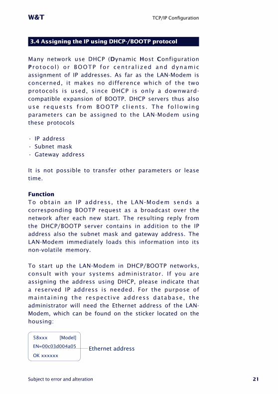
To start up the LAN-Modem in DHCP/BOOTP networks,consult with your systems administrator. If you areassigning the address using DHCP, please indicate thata reserved IP address is needed. For the purpose ofmainta in ing the respect ive address database, theadministrator will need the Ethernet address of the LAN-Modem, which can be found on the sticker located on thehousing:
58xxx [Model]
EN=00c03d004a05
OK xxxxxxEthernet address
22
W&T TCP/IP Configuration
After the administrator has made the necessary entries, theLAN-Modem will automatically obtain the desired IP addressafter each reset. To ensure the availability of the LAN-Mo-dem even should the DHCP/BOOTP server fail, the previousIP address is kept if no reply comes.
1In DHCP environments the IP address to be assignedmust be reserved by means of a fixed link to the
Ethernet address of the LAN-Modem. Under Windows NT thisis done in the DHCP manager under the menu item Reservat-ions. Linux provides the file dhcpd.conf for this purpose, inwhich a corresponding entry must be added.
3.4.1 Deactivating the DHCP-/BOOTP protocol
A DHCP server assigns IP addresses dynamically from anaddress pool provided by the administrator. This meansthat DHCP-compatible devices usually receive another IPaddress after starting. Since a constantly changing IPaddress is not something you want to have with the LAN-Modem, the latter uses BOOTP protocol, which is basedon fixed Ethernet-to-IP address assignments. DHCPservers should reply to BOOTP requests only if they havean explicit IP reservation for the Ethernet address of thesender.
Some DHCP servers (e.g. Windows 2000 servers) howeveruse both DHCP and BOOTP requests from their dynamicaddress pool. To prevent the LAN-Modem from beingassigned unknown IP addresses in such environments,the following options are available:
• A reservation must be made in the respective DHCPserver before connecting the LAN-Modem to thenetwork.

23
W&T TCP/IP Configuration
Subject to error and alteration
• The serial port is used to assign the IP address for theLAN-Modem. By sending „xxx“ to the LAN-Modem duringa restart, you arrive at the input mode for a new IPaddress. If you enter this followed by the string „-0“, theBOOTP client of the LAN-Modem will be deactivated (seesection 3.2 Assigning the IP through the serial port).
In existing systems the BOOTP client of the LAN-Modem canalso be deactivated and activated whenever desired using theTelnet configuration under „SETUP System r SETUP TCP/IP rBOOTP Client.
For an explanation of the basic terms and concepts foraddressing in the Internet, as well as information aboutDHCP and BOOTP, please see our manual „TCP/IP-Ethernet and WEB-IO“.
iOlder Windowssystems will onlyaccept a static entryif a dynamic entrywas already present.First send a PING toanother networkstation.

24
W&T TCP/IP Configuration
3.5 Configuring the subnet mask and gateway
When working in routed environments, the LAN-Modem mustbe told the responsible router in addition to the subnetmask which is valid for the respective network segment.Valid values for both parameters can be obtained from yoursystems administrator. The LAN-Modem provides a Telnetconfiguration menu under port number 1111 for enteringthis.
Under Windows 95/98/NT the Telnet client is started underStart r Run ... using the following command line:
telnet [IP address LAN-Modem] 1111
If the Telnet client is already active, you can establish aconnection under Connect r Remote-System... . In the fieldHost-Name enter the IP address and next to Port enter 1111.
If a connection could be established, the LAN-Modem willdisplay the following menu on your monitor:
****************************
* MINI Com-Server *
***************************
1. INFO System
2. SETUP System
3. SETUP Port 0 (Serial)
4. SAVE Setup

25
W&T TCP/IP Configuration
Subject to error and alteration
The entry fields for the subnet mask and the gatewayaddress are reached through the following menu path:
3. SETUP Port 0
Always save using"SAVE Setup"
in order to activatethe new settings!
1. INFO Com Server
2. SETUP System
4. SAVE Setup
2. Set Password3. Flash Update4. Factory Defaults5. Reset
Takes the selected parameters and saves allsettings in non-volatile memory (EEPROM)of the LAN-Modem
1. Setup TCP/IP 1. IP-Address2. Subnet Mask3. Gateway4. MTU (512-1024)
Once the settings have been made, they must be loaded intothe non-volatile memory of the LAN-Modem by selecing 4.SAVE Setup. Then you may close the Telnet session.
The network-side configuration of the LAN-Modem is nowcomplete. You can PING to check whether all the settingshave been correctly made. In routed environments, theLAN-Modems must a lso be reachable by other IPnetworks that are incorporated into the infrastructure.

26
W&T

27
W&T
Subject to error and alteration
4 Modem Operation
After the netework configuration is complete, the LAN-Modem
behaves on the serial side just like a dial-up modem with an AT
command set, except that the TCP/IP LAN takes the place of the
telephone line. As far as the controlling application or controlling
device is concerned, all that needs to happen is that the previously
used telephone number is replaced by the IP address of the distant
terminal.
■ Serial transmission parameters
■ Command syntax
■ List and explanation of all AT commands
28
W&T Modem Operation
4.1 Serial transmission parameters
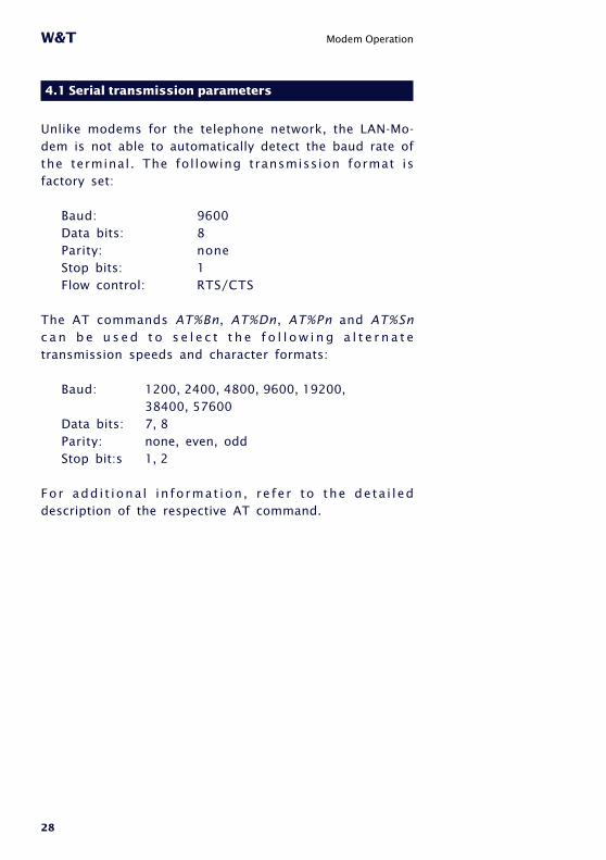
Unlike modems for the telephone network, the LAN-Mo-dem is not able to automatically detect the baud rate ofthe terminal. The fol lowing transmission format isfactory set:
Baud: 9600Data bits: 8Parity: noneStop bits: 1Flow control: RTS/CTS
The AT commands AT%Bn, AT%Dn, AT%Pn and AT%Snc a n b e u s e d t o s e l e c t t h e f o l l o w i n g a l t e r n a t etransmission speeds and character formats:
Baud: 1200, 2400, 4800, 9600, 19200,38400, 57600
Data bits: 7, 8Parity: none, even, oddStop bit:s 1, 2
For add i t iona l in format ion , re fer to the deta i leddescription of the respective AT command.
29
W&T Modem Operation
Subject to error and alteration
4.2 Command syntax
The LAN-Modem accepts all the AT described in thefollowing sections as long as they corresponding to oneof the following patterns and are finished with a CR:
letter [number]& letter [number]% letter [number]\ letter [number]
Non-supported AT commands, such as %V or L2 have noeffect and are simply ignored. Invalid commands on theother hand generate an error message and in particularend processing of the current command line. Example:„AT&C0*H0Q1" would run command &C0 , but not Q1,since the line is no longer considered starting with theinvalid command *H0.
30
W&T Modem Operation
4.3 Command and data mode
The LAN-Modem distinguishes on the serial side between twomode states: command and data mode.
• Command modeIn this mode, which is activated after power-on, theAT command interpreter operates on the serialinterface. The LAN-Modem is in this state ready toreceive and process AT commands. All data notc o r r e s p o n d i n g t o A T s y n t a x i s i g n o r e d o racknowledged with an error message. Nothing ispassed on to any communications partner in thenetwork. The command ATO can be used to switchfrom command to data mode during any existingnetwork connection.
• Data mode (Online mode)This mode i s on lyh ava i l ab le wh i le there i s aconnection to a communications partner. The ATcommand interpreter is now deactivated and allincoming serial data are passed into the networkwithout any further processing. To switch back intocommand mode, use the escape sequence „+++“. Toretain the binary transparency of data mode inspite ofthe processing of this character string, the LAN-Mo-dem only carries out the change if the following timesare observed:minimum 1s no data received rEscape sequence r1s no data receivedIf this procedure should be unusable in sepcial cases,the S registers 2 and 12 can be used to modify theEscape characters as well as the pause time (seecommand Sn=x ) . As an alternative to use of theEscape sequence, the RS232 input DTR can beconfigured for switching into command mode. FOrdetails, see the description of the AT command &Dn.

31
W&T Modem Operation
Subject to error and alteration
4.4 All AT commands
The LAN-Modem accepts all the commands in the tablewhose processing is done according to the followingrules:
Befehl
Dx
A
O
H
Zn
En
Qn
Vn
In
Sn?
Sn=x
&Cn
&Sn
&Dn
&Kn
&Fn
&Vn
&Wn
&Yn
&Zn=x
%Bn
%Dn
%Pn
%Sn
%Nn
**n
Beschreibung
IP-Adresse anwählen und online gehen
Ankommenden Ruf annehmen
Zu einer bestehenden Verbindung zurückkehren
Verbindung beenden
Verbindung beenden und Modem zurücksetzen
lokales Echo ein|aus
Ergebniscodes unterdrücken ein|aus
Ergebniscodes als Text statt als Zahl
Firmwareinformation
S-Register auslesen
S-Register ändern
DCD nur bei Verbindung aktiv ein|aus
DSR nur im Online-Modus aktiv ein|aus
Funktion des DTR-Eingangs
Flußkontrolle zwischen Modem und Terminal
Werkseinstellungen wiederherstellen
Konfigurationsprofile/Verbindungsdaten anzeigen
Konfiguration im nichtflüchtigen Speicher ablegen
Standardprofil, das beim Einschalten aktiv ist
Ziel-IP (Telefonnummer) speichern
Baudrate zwischen Modem und Terminal
Anzahl der Datenbits zwischen Modem und Terminal
Paritätsbit zwischen Modem und Terminal
Anzahl der Stopbits zwischen Modem und Terminal
Fernwartung über Netzwerk erlauben
Firmware-Update starten
Parameter
IP-Adresse
---
---
---
n=0, 1
n=0, 1
n=0, 1
n=0, 1
n=0 - 8
n=0 - 40
n=0 - 255
n=0, 1
n=0, 1
n=0, 1, 2, 3
n=0, 3, 4, 5, 6
n=0, 1
n=0, 1, 2
n=0, 1
n=0, 1
n=0, 1, 2, 3
n=2 - 8 (5)
n=7, 8
n=0, 1, 2
n=1, 2
n=0, 1
n=0, 1

32
W&T Modem Operation
• No other command may follow A, D, O, Z and &Z in thesame command line. In the case of A, O and Z they areignored, and in the case of D and &Z they are consideredas part of the dialed number.
• Omitting a numerical parameter has the same effectas indicating a 0.
• The boldface parameters are the standard values thatare created by AT&F.
In addition to these commands, A/ (without a precedingAT or concluding <cr>) is accepted as an entry tocompletely repeat the last command line again.
4.4.1 A (ATA)
= accept incoming call
If the serial application detects an incoming call bymeans of the RING sequences send by the LAN-Modem,the call can be picked up by sending this command. Af-ter the network connection with the communicationpartner has been established, the LAN-Modem sends themessage „CONNECT“ over the ser ia l interface andautomatically switches to data mode.
Along with each serial output of the „RING“ characterstring, an incoming connection request causes theinterface signal RI (=Pin 9) to be set high for approx. 1s.

33
W&T Modem Operation
Subject to error and alteration
4.4.2 D (ATD[IP address])
= Dial command
The d ia l command is requi red for estab l ish ing aconnection with another LAN-Modem. Taking the place ofthe dial-up number used in telephone networks is the IPaddress o f the des i red LAN-Modem. To mainta incompatibility with existing modem applications, the LAN-Modem accepts here the following formats:
D [Options] IP address [;]D [Options] S=n [;]D L [;]
• OptionsOptions may consist of any number of letters andspecial characters; these characters have no effect onthe connection set-up. By this means it is possible tocontinue using an application that employs at thispoint for example a „T“ for using tone dialing.
• IP addressThe IP address consists of four numbers between 0and 255 in decimal format. These can be separated byspecial characters (e.g. decimal point or comma).Without separators it is assumed that each numberconsists of exactly three digits. If additional digitsfollow behind the last number, these are intereted asTCP port numbers. If no port number is specified, portnumber 8000 is implied. Valid entries would includefor example.:
1720162320731720162320738000172.16.232.73172.16.232.73:8000
34
W&T Modem Operation
• S=0|1|2|3The LAN-Modem has a non-volatile memory for up to fourdestination IP addresses. By specifying a value between0 and 3, the IP addresses stored here is used for the callset-up. If only „S“ is entered without a numerical value,the addresses stored in position 0 is used. The command&Zn is used to write to the non-volatile address memory.
• LWhen using „L“ instead of the IP address, the dial-upis repeated using the last used values. If no addresshas been dialed since the last reset of the LAN-Mo-dem, the message „ERROR“ is returned.
• ; (Semicolon)Entering a semicolon to terminate the dial-up commandcauses the LAN-Modem not to automatically return todata mode after a successful call set-up, but rather toremain in command mode.
Example of dial-up command:
ATD172.16.1.1ATD172016001001ATDT172.16.001.001
All three commands have the same effect: An attempt ismade to set up a call to the LAN-Modem having IPaddress 172.16.1.1.

35
W&T Modem Operation
Subject to error and alteration
Replies for the dial-up command• CONNECT
The network connection with the desired destinationsys tem was success fu l l y made , and the ser ia lapplication connected therre accepted the call. If the dial-up command was not terminated with a semicolon, theLAN-Modem is now in data mode, i.e. all entries are senttransparently to the communication partner
• NO CARRIERT h e n e t w o r k c o n n e c t i o n t o t h e d e s i r e dcommunication partner was able to be established,but the serial application there did not pick up thecall. The time for which the LAN-Modem waits for thecounterpart to pick up the call is stored in Register S7and is factory set to 50s.
• BUSYNo network connection to the desired communicationpartner could be established. The cause of this maybe a stat ion that is a l ready busy with anotherconnection. In this case the attempt to establish aconnection is rejected. Another reason may be anunreachable or incorrect IP address. For very slownetwork routs to the destination system, the timeoutstored in Register S6 for the TCP connection set-up canbe set to a higher value. The factory setting is for 3s
36
W&T Modem Operation
4.4.3 E (ATE[0|1])
= local echo off|on
This command determines whether the data received on theRS232 interface in command mode should lbe returned. Thefactory setting is for echo on.
ATE0 = Echo offATE1 = Echo on
4.4.4 H (ATH)
= Quit connection
Th is command qu i t s the connec t ion . Bo th se r ia lcommunication partners receive the reply „NO CARRIER".
4.4.5 In (ATI[0–8])
= Read out firmware information
The I command is used to read out system informationfor the LAN-Modem. Of a possible 0-8, only parameters 0and 3 are presently used. The remaining even options arereserved for later enhancements.
• ATI0Returns product code „58210" from the LAN-Modem
• ATI8Returns the firmware version of the AT commandinterpreter

37
W&T Modem Operation
Subject to error and alteration
4.4.6 O (ATO)
= Switch to data mode
This command switches (when there is an existingconnection) from command to data mode. If you need forexample to change LAN-Modem parameters during aconnection, you must first use the Escape sequence tos w i t c h t o c o m m a n d m o d e . A f t e r t h e d e s i r e dreconfiguration you can then use the ATO command toreactivate data mode.
For additional information: Section 4.3 „Command andData Mode"
4.4.7 Q (ATQ0|1)
= Modem replies on|off
Default setting: 0 = ON
Replies generated by the LAN-Modem such as „OK“ or„CONNECT“ can be turned off by using the Q command:
• ATQ0The LAN-Modem sends replies
• ATQ1Reply messages are turned off.
4.4.8 Sn? (ATS[0-40]?)
= Read S register
This command is used to read the 41 S registers thatdetermine the operating behavior of the LAN-Modem.Changing or writing to the S registers is done using the Sn=xcommand shown below.
!
38
W&T Modem Operation
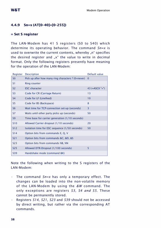
4.4.9 Sn=x (AT[0–40]=[0–255])
= Set S register
The LAN-Modem has 41 S registers (S0 to S40) whichdetermine its operating behavior. The command Sn=x isused to overwrite the current contents, whereby „n“ specifiesthe desired register and „x“ the value to write in decimalformat. Only the following registers presently have meaningfor the operation of the LAN-Modem:
Register
S0
S1
S2
S3
S4
S5
S6
S7
S9
S10
S12
S14
S21
S23
S25
S39
Description
Pick up after how many ring characters ? (0=never)
Ring counter
ESC character
Code for CR (Carriage Return)
Code for LF (Linefeed)
Code for BS (Backspace)
Wait time for TCP-connection set-up (seconds)
Waits until other party picks up (seconds)
Time base for carrier generation (1/10 seconds)
Allowed Carrier dropout (1/10 seconds)
Isolation time for ESC sequence (1/50 seconds)
Option bits from commands E, Q, V
Option bits from commands &C, &D, &S
Option bits from commands %B, %N
Allowed DTR-Dropout (1/100 seconds)
Handshake mode (command &K)
Default value
0
43 (=ASCII "+")
13
10
8
3
50
20
50
5
Note the following when writing to the S registers of theLAN-Modem:
• The command Sn=x has only a temporary effect. Thechanges can be loaded into the non-volatile memoryof the LAN-Modem by using the &W command. Theonly exceptions are registers S3, S4 and S5. Thesecannot be permanently stored.
• Registers S14, S21, S23 and S39 should not be accessedby direct writing, but rather via the corresponding ATcommands.
39
W&T Modem Operation
Subject to error and alteration
� The value of register S9 is adjusted to the value of S10each time a connection is set up.
4.4.10 Vn (ATV[0|1])
= Result codes in plain text
Default setting: 1 = ON
This command specifies whether result returns from theLAN-Modem are to be numerical or in plain text. Thefollowing messages and result codes are possible:
0 = OK 1 = CONNECT2 = RING 3 = NO CARRIER4 = ERROR 4 = BUSY
• V0Replies will be numerical in decimal format.
• V1Replies will be in plain text.

40
W&T Modem Operation
4.4.11 Zn (ATZ[0|1])
= Reset the LAN-Modem
The Zn command quits any active connection and resets thefirmware of the LAN-Modem to the parameters stored in thenon-volatile memory. By specifying „0“ or „1“ you can selectone of the two available reset profiles (see also &Wncommand). Which profile is loaded after the LAN-Modem isturned on is defined by the &Yn command.
• Z0Load stored reset profile 0.
• Z1Load stored reset profile 1.
4.4.12 &C (AT&C[0|1])
= DCD Option
Default setting: 1 = ON
This command defines the behavior of the DCD interfaceoutput:
• &C0DCD is always active regardless of the network-sideconnection status.
• &C1DCD is only active if there is a connection to acommunication partner.

41
W&T Modem Operation
Subject to error and alteration
4.4.13 &D (AT&C[0|1|2|3])
= Modem response to DTR option
Default setting: 2
Defines the effect of a level change on the DTR input on theLAN-Modem. One of four functions may be selected:
• &D0The LAN-Modem ignores the signal.
• &D1If the LAN-Modem is in data mode,k an ON r OFF changeplaces the modem in command mode. The ATO commandcan be used to return to data mode.
• &D2A change from ON r OFF breaks the existing connection.A new connection can only be established when an enablelevel is present on DTR.
• &D3Has the same function as &D2 but additionally it resetsthe LAN-Modem. If the LAN-Modem is on data mode, alevel change on the DTR input is only recognized if it ispresent for the time defined in S-register 25.
4.4.14 &Fn (AT&F[0|1])
= Restore
The LAN-Modem has two factory settings which can beinvoked using the commands AT&F and AT&F1 . Thedefaults specified by the individual commands refersbasically to the factory profile 0. Factory profile 1 differshere in the function of the DTR input (&D0 instead of &D2)and in the flow control (&K0 instead of &K3).

42
W&T Modem Operation
4.4.15 &K (AT&K[0|3|4|5|6])
= Flow control
Default setting: 3 = RTS/CTS
This command determines the flow control between the LAN-Modem and the connected serial device:
• &K0 (no handshake)Flow control is turned off. The LAN-Modem sends all datato the serial device regardless of the status of thehandshake input RTS. In the opposite direction the LAN-Modem has no way to report an impending overflow ofits input buffer through the CTS output, so that in thiscase the serial applications are responsible for ensuringdata integrity.
• &K3 (RTS/CTS)Flow control is handled by the port signals RTS andCTS. The LAN-Modem sends serial data only whenthere i s an enab le l eve l on i t s RTS input . Animpending overflow of the serial input buffer is signaledby the CTS output.
• &K4 (Xon/Xoff)Flow control is handled by the control characters Xon(hex 11) and Xoff (hex 13), whereby these charactersare filtered out from the user data stream. If the LAN-Modem receives an Xoff, no additional data are sentto the serial device until the latter has sent an Xon.The LAN-Modem indicates its ready or not-ready statuslikewise using an Xoff or Xon.
• &K5 (transparent Xon/Xoff)As in the case of &K4 the flow control is handled byXon/Xoff. The control characters are now however notf i l tered out, but rather sent transparent to thecommunication partner.
43
W&T Modem Operation
Subject to error and alteration
• &K6 (RTS/CTS + Xon/Xoff)Flow control is handled by RTS/CTS and Xon/Xoff. Themodem genera tes s igna ls fo r both handshakeprocedures and allows itself to be prevented fromcontinuing to send by means of Xoff or a returned RTS.
4.4.16 &Sn (AT&S[0|1])
= DSR Option Selection
Default setting: 0
This command defines the behavior of the DSR output:
• &S0The DSR output is always enabled regardless of theconnect ion status and regard less of the mode(command or data).
• &S1DSR is only enabled if the LAN-Modem has an activeconnection in data mode.
4.4.17 &Vn (AT&V[0|1|2])
= Display system information
This command causes the LAN-Modem to output itsconfiguration and connection data:
• &V0Provides the current configuration data as well as thedata stored in non-volat i le profi les 0 and 1. Inaddition, the stored destination addresses are output.

44
W&T Modem Operation
• &V1The LAN-Modem returns statistics for the last TCP/IPconnection.
• &V2The LAN-Modem sends as a reply i ts completeconfiguration coded in S record format. By sending thisdata record to another modem, it is possible for exampleto copy configurations over the network.
For additional information, see section 6 „Copying theconfiguration data").
4.4.18 &Wn (AT&W[0|1])
= Active Profile Write
This command is used to write the two non -volatileconofiguration profiles 0 and 1 which the LAN-Modemprovides. The current settings are written to the memorylocation defined by „n“. The configuration profiles arespecified by the command Zn. Which of the two profilesis active after the LAN-Modem is turned on is defined bythe command &Yn.
4.4.19 &Yn (AT&Y[0|1])
= Active Profile Read
This command specifies which of the two configurationsstored in the profiles the LAN-Modem uses after beingturned on or after a reset. Additional information can befound in the following sections:
Zn: Reset modem to Profile 0 or 1&V1: Read the configuration profiles&Wn: Store the current settings in the specified profile

45
W&T Modem Operation
Subject to error and alteration
4.4.20 &Zn=x (AT&Z[0|1|2|3]=[IP address])
= Save destination IP address
The LAN-Modem can save up to 4 destination IP addresses inits non-volatile memory, which can later be recalled using thefast dial function (Sn=x) of the dial command.
Example: AT&Z1=172.16.2.2IP address 172.16.2.2 is stored in memory location 1.ATDS=1 can now be used to establish a connection with thisaddress.
4.4.21 %Bn (AT%B[2-8])
= Modem Port Bps Rate
Default setting: 5 (9600 Baud)
This command is used to set the baud rate. The followingspeeds are available:
Command
%B2
%B3
%B4
%B5
%B6
%B7
%B8
Baudrate
1200
2400
4800
9600
19200
38400
57600
1The %B command has a delayed effect. The first OK reply is still with the old baud rate.
Successive commands in the same command line (such as &Wfor saving) are ignored. This ensures that any inadvertentchange in the baud rate can be restored by resetting theLAN-Modem.
46
W&T Modem Operation
4.4.22 %Dn (AT%D[7|8])
= Number of data bits per character
Default setting: 8
This command determines whether the serial characterformat works with 7 or 8 data bits.
1 The %D command has a delayed effect. The first OK reply is still with the old data format.
Successive commands in the same command line (such as&W for saving) are ignored. This ensures that anyinadvertent change in the baud rate can be restored byresetting the LAN-Modem.
4.4.23 %Pn (AT%P[0|1|2])
= Specifying the parity bit
Default setting: 0 = no parity
This command determines if and, if yes, what parity is usedfor the serial data format.
• %P0 = no parity• %P1 = odd parity• %P2 = even parity
1 The %P command has a delayed effect. The first OK reply is still with the old data format.
Successive commands in the same command line (such as&W for saving) are ignored. This ensures that anyinadvertent change in the baud rate can be restored byresetting the LAN-Modem.
47
W&T Modem Operation
Subject to error and alteration
4.4.24 %Sn (AT%S[1|2])
= Minimum number of stop bits between 2 characters
Default setting: 1= 1 stop bit
This command determines how many stop bits (minimum)appear between 2 serial characters.
1 The %S command has a delayed effect. The first OK reply is still with the old data format.
Successive commands in the same command line (such as&W for saving) are ignored. This ensures that anyinadvertent change in the baud rate can be restored byresetting the LAN-Modem.
4.4.25 %Nn (AT%N[0|1])
= Remote maintenance over the network allowed
Default setting: 1 = allowed
Loading firmware updates and copying configuration data ispossible either through the serial port or over the network.To protect against misuse of network-side remotemaintenance, the &N command makes it possible tosuppress this functionality.
Additional information: Section 5 „Firmware-Update" andSection 6 „Copying Configuration Data"

48
W&T Modem Operation
4.4.26 ** (AT**)
= Start flash update
Updating the firmware or sending a configuration file mustbe introduced with the ** command. The LAN-Modemgenerates the following message and then expects theupdate data in Motorola S Record format. If no data are sentwithin 30s, the mode is automatically quit.
MB90F562 bootloader v1.x W&T xx/xxxx
Invoked by software, ESC to cancel
Waiting (Port 0)...
Additional information: Section 5 „Firmware-Update" andSection 6 „Copying Configuration Data".

49
W&T
Subject to error and alteration
5 Firmware-Update
The firmware for the LAN-Modem is divided into two function
modules whoses update methods differ.
■ Update the AT command interpreter serially or over the network
■ Update the TCP/IP-Stack over the network
50
W&T Firmware-Update
5.1 Where do I get the latest firmware?
The current firmware including the update tool and arevision list is published on our Web site at the followingaddress: http://www.wut.de.
Before proceeding with the update, please write downthe 5-digit model number located on the LAN-Modem.From our homepage you can now find the productoverview sorted by article numbers, from which youarrive directly at the Web data sheet for the respectiveLAN-Modem model. Then follow the link to the currentversion of the firmware.
1 Never interrupt the update process by pulling the power plug or pressing the reset key. The Com-Ser-ver will be made inoperable following an incompleteupdate.
Never mix files having different version numbers in thefile name. This will make the device inoperable.
Transmi t a l l the f i l e s i n o rder . The Com-Serverautomatically detects when all the files have been sentand the new operating software is complete. It will thenautomatically perform a reset.
51
W&T Firmware-Update
Subject to error and alteration
5.2 Serial update of the AT command interpreter
For this the LAN-Modem must have a serial connection to aterminal program whose transmission parameters areconfigured as follows:
Baud rate: same as the LAN-ModemData format: 8 data bits, no parity, 1 stop bitHandshake: RTS/CTS (required)
The command AT** is used to place the LAN-Modem inserial update mode, which is acknowledged with thefollowing message:
MB90F562 bootloader v1.x W&T xx/xxxx
Invoked by software, ESC to cancel
Waiting (Port 0)...
The function „Send text file" of the terminal program cannow be used to sent the mhx-fi le with the currentfirmware. The LAN-Modem sends a continuous bytecounter dur ing the t ransmiss ion and returns themessage „OK“ after successful completion of the update.The new firmware version can now be checked using thecommand AT13.
1 You cannot use the binary data transmission function offered by terminal programs, since thisuses additional protocols such as ZModem or Kermit.
The update mode is protected with a timeout of 30s. If nodata are transmitted within this time, the LAN-Modemautomatically resumes normal operating mode.
52
W&T Firmware-Update
5.3 Network update of the AT command interpreter
Updating the firmware over the network offers the advantageof a higher speed compared with the serial method. Theprerequis i te however is that network-s ide remotemaintenance be enabled by the command %N1.
After establishing a TCP socket connection to Port 8000 onthe LAN-Modem, the latter returns a short identifier. If this isreplied to within three seconds with the character „U“, updatemode is started with the following message.
MB90F562 bootloader v1.x W&T xx/xxxx
Invoked by software, ESC to cancel
Waiting (Port 1)...
As in the case of a serial update, the LAN-Modem nowexpects the update data in S record format. UnderWindows the following method using a Telnet client andpasting from the clipboard has proven useful.
Example with Telnet client under Windows 95/98/NT
1. Open the mhx file with the LAN-Modem firmware in aneditor and copy the entire contents to the clipboard.
2. From Start r Run r telnet [IP address] 8000 on a Windowsmachine having a TCP/IP stack, the network connectionto the LAN-Modem is established and the message„Wxxxx" appears.
3. Entering a „U“ within the first three seconds activatesupda te mode , and the LAN -Modem sends thecorresponding reply.
4. Use Edit r Paste to copy the firmware from the clipboardto the LAN-Modem.
5. After a successful update the LAN-Modem breaks the TCPconnection. Any transmission errors are reported withreferenced to a checksum error.
53
W&T Firmware-Update
Subject to error and alteration
1 When starting update mode over the network, the serially connected device is informed of the accesswith a short message.
The update mode is protected with a timeout of 30s. If nodata are transmitted within this time, the LAN-Modemautomatically resumes normal operating mode.
If updating over the network is automated in any way,you must ensure a pause of at least 0.5 seconds betweens e n d i n g o f o t h e „ U “ a n d t h e s t a r t o f f i r m w a r etransmission. The LAN-Modem needs this time to deletethe internal serial receive buffer when switching over toupdate mode.

54
W&T Firmware-Update
5.4 Updating the TCP/IP-Stack
Prerequisite is a PC running under Windows 9x/NT/2000with a network connection and an installed TCP/IP stack.You need two files for the update process:
1. The Update-Tool (32-bit application for Windows9x/NT/2000), used to perform the update, and
2. the file with the extension *.bin (e.g. C4r1_0.bin),which contains the new operating software for theLAN-Modem. This file is sent to the LAN-Modem.
The update process is described in steps below. Pleasefollow these instructions exactly. After an incompleteupdate the device will no longer be operable!
1. Close all connections that may still be active on theLAN-Modem. Before the update process all buffers andtheir contents are deleted!
2. Start the remote configuration tool of the LAN-Modemvia Telnet
telnet [IP address] 1111
Select the following in the SETUP menu: System r FlashUpdate r Net Update and confirm with y. The LAN-Modemcloses the Telnet connection, and the green status LEDindicates that it is now in update mode.
3. Now star t the update too l . The menu path CSprogramming r Flash takes you to the input screen foruploading the new firmware.
4. Enter the IP address for the LAN-Modem as well s thename of the firmware file in the corresponding fields.

55
W&T Firmware-Update
Subject to error and alteration
IN the option field „Output“ please select only the item„Firmware“.
5. Click on the Start button. The update will take severalsecnds. It is only finished when a message windowreports the end of the update process.
6. Check in the configuration menu of the LAN-Modem toverify that the new operating software was loaded. Themenu INFO System r SOFTW Date/Rev must now showthe new version number of the firmware.
If the old version is still displayed, the file with the newoperating software is corrupted. Please contact yourdealer for assistance.
1The procedure described here for the update onlyapplies to version 1.14 and higher of the TCP/IP
stack. LAN-Modems with a lower version of othe TCP/IP stackmust first be upgraded to 1.14 or higher. Note here thatonly the destination IP address and the name of the newfirmware may be entered in the input screen for the update.In the opt ion f i e ld , however , bo th f i rmware andconfiguration must be activated.

56
W&T

57
W&T
Subject to error and alteration
Appendix
■ Reading and sending complete configuration profiles
■ The modem protocol on the TCP level
■ Using with W&T COM Port Redirector and virtual modem ports
■ Technical Data

58
W&T Appendix
Reading/Sending Configuration Profiles
To simplify the configuration of the LAN-Modem whenusing a greater number of devices, it is possible to copythe configuration data. To do this, you must f irstconfigure a LAN-Modem for the desired operating modeusing the AT commands. In the ext step you use &Wn tosave these configuration data in one of the two non-volatile profiles. Then use the command &V2 to read theentire conofiguration in S record format and store it in afile.
The upload of the configuration data to other LAN-Mo-dems can be done either over the serial interface or overthe network. The procedure is then identical to thatdescribed in Section 5 for updating the AT commandinterpreter.
59
W&T Appendix
Subject to error and alteration
The Modem Protocol on the TCP Level
Normally LAN-Modems will be used only to connect toeach other. It is however conceivable that an applicationprogram uses TCP/IP programming to direct dial anindividual LAN-Modem or to be called by the LAN-Modem.The information required for doing this can be obtainedon request.

60
W&T Appendix
Virtual Modem Ports under Windows NT/2000/XP
As is the case with standard dial-up modems, the LAN-Modems are generally used in pairs, with one LAN-Mo-dem used to dial-up another. If in a serial application thisinvolves an application running under Windows NTW,2000 or XP, a LAN-Modem is not required on this side.
The COM Port Redirector for WIndows NTW/2000/XPallows you to create virtual COM ports with an integratedAT command interpreter. Whenever an application openssuch a virtual modem port, the latter behaves just like alocal COM port with an externally connected hardwareLAN-Modem. Both incoming and outgoing connectrionsare possible.
Where do I get the COM Port RedirectorThe latest version can always be downloaded at nocharge from our Web site under the following address:
http://www.wut.de
Before proceeding with the update, please write downthe 5-digit model number located on the LAN-Modem.From our homepage you can now find the productoverview sorted by article numbers, from which youarrive directly at the Web data sheet for the respectiveLAN-Modem model. Then follow the link to the currentversion of the COM Port Redirector for Windows NT/2000/XP.

61
W&T Appendix
Subject to error and alteration
Technical Data
typ. 270mA
typ. 455mA
typ. 80mA
typ. 175mA
0 - 60°C
0 - 60°C
0 - 60°C
0% - 95%
105 x 75 x 22mm
ca. 110g
max. 330mA
max. 575mA
max. 110mA
max. 225mA
Spannungsversorgung
Typ 58210:
Typ 58220:
Typ 58610@24V/DC:
Typ 58620@24V/DC:
zulässige Umgebungstemperatur beifreier Luftzirkulation, nicht angereiht:
Typ 58210, 58220, 58610, 58620:
zulässige Umgebungstemperatur beiangereihter Montage auf Hutschiene:
Typ 58210, 58610:
Typ 58220, 58620:
zulässige Luftfeuchtigkeit,nicht kondensierend:
Abmessungen58210, 58220, 58610, 58620:
Gewicht 58210, 58220, 58610, 58620:
62
W&T Appendix
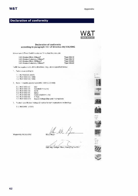
Declaration of conformity

W&T