Embed Size (px)
Citation preview

Diagraph Ink Delivery SystemStand-Alone
(IDS/SA)
5802-677Revision D
User’sManual
Diagraph Corporation • 3401 Rider Trail SouthSaint Louis / Earth City, MO • 63045 • © 2000

Rev D - IDS/SA - 1
IDS/SA TABLE OF CONTENTS
1 IDS/SA TABLE OF CONTENTS ______________________ 1
IDS/SA SPECIFICATIONS ______________________________ 2
Views _________________________________________________ 3
2 Configuring the IDS/SA ______________________________ 4
Ink Line Connections to the IDS/SA _______________________ 5
Plumbing the system ____________________________________ 5
Connecting the Beacon to the IDS/SA ______________________ 8Connecting to the Ink Pail_____________________________________ 8
Powering Up the IDS/SA ________________________________ 10
PRIMING ____________________________________________ 10
FLUSHING THE PRINTHEADS ________________________ 12
CHECKING INK PRESSURE ___________________________ 13
3 Maintaining the IDS/SA_____________________________ 15
CHANGING INK CONTAINERS ________________________ 15
Changing Non-Porous Ink (Labeled “TSO”) _______________ 16
Changing Porous Ink (Labeled “TWP”)___________________ 18
Ink Regular Maintenance _______________________________ 19
4 TROUBLESHOOTING THE IDS/SA__________________ 21
ERROR CONDITIONS_________________________________ 21INDICATION SIGNALS ____________________________________ 21
5 IDS/SA Parts & Inks________________________________ 29
Spare Parts Kit (5700-778) ______________________________ 29
INKS ________________________________________________ 30Compatible Inks ___________________________________________ 30
Appendix A - Replacing the Pump ______________________ 31
Appendix B – Air Purge Valve Removal __________________ 34
The information contained in this manual is correct and accurate at thetime of its publication. Diagraph reserves the right to change or alter anyinformation or technical specifications at any time and without notice.
© 2000 Diagraph, Inc. All rights reserved.Printed in the United States of America

Rev D - IDS/SA - 2
IDS/SA SPECIFICATIONS _____________________________________
Size Height: 5.0 inches (12.7 cm)6.0 inches (15.24 cm) with feet attached
Width: 8.25 inches (20.96 cm)Depth: 15.0 inches (38.1 cm)
Weight 18 pounds
Electrical Connections 115 VAC at 60 Hz or 230 VAC at 50 Hz input power
Fluid Connections 1/8 inch female coupling for ink inlet1/4 inch female coupling for ink outlet
Manual ControlsControl Location FunctionMode Switch Front Panel ON/OFFVoltage/Fuse Selector Front Panel Voltage SelectionPump Prime Button Front Panel Over-ride
auto-shutoffAir Purge Button Rear Panel Evacuates system
of air.
Enclosure Industrial Grade Stainless Steel
Ink Accumulator Capacity 1.4 oz (40ml) ink available for printing
Operating Temperature Between 40˚F to 100˚F (4.4˚C to 37.8˚C)
Fuses System: 2 MDL-2 250V, 2A Fan: 1 125V, 315 mA
Diagraph PrintheadSupply Capacities
IV Printhead Size Max No.Printheads1/2” 127/8” 82” 4Barcode 4
0
2
4
6
8
1 0
1 2
1 4
1 6
1 8
0 5 10 15 2 0 2 4
Height in Feet
ON/Off Pressure (PSIG)
Pum p On P ressure
Pum p Off Pressure
M inim um Pressure

Rev D - IDS/SA - 3
Views _____________________________________________________
115V
STATUS LEDPRIME BUTTON
MODE SWITCH
AC POWER INLET
FAN
AUXILIARYCONNECTOR
AIR PURGE BUTTON
1/8 INCH INK IN 1/4 INCH INK OUT
Front View - IDS/SA
Rear View - IDS/SA

Rev D - IDS/SA - 4
Configuring the IDS/SA 2
The illustration below shows the plumbing of a multiple printheadsystem.
EE
1 Printhead
2 Ink Regulator
3 Pressure Gauge
4 Shutoff Valve
5 T Connector
6 Effluent Bottle
7 Beacon
2
7
3
1
4
6
5 2
8
10
11
12
9
13
8 Ink Filter
9 1/8" Ink L
10 Elbow Fitti
11 IDS/SA
12 1/4" Ink Li
13 Ink Contain

Rev D - IDS/SA - 5
Ink Line Connections to the IDS/SA ____________________________
These instructions presuppose the installation of bracketry and withprintheads and ink regulators.
Requisite parts of a new system
The IDS/SA ships with
! 20 feet of 1/4 inch tubing with a male elbow in one end (theIDS/SA connection) and a 1/4 inch male coupling in the other;
! an ink filter assembly comprised of 1/8 inch tubing, a filterand a 1/8 inch male coupling in each end;
! a beacon;! a power cord;! two mounting brackets;! spare parts kit;! documentation.
Even a single printhead system will need all of these items plus apressure gauge and an effluent bottle.
The previous illustration shows these items in a normal twoprinthead plumbing configuration.
Plumbing the system ________________________________________
"""" Setting up the primary ink line
Before starting, get a pair of diagonal cutters to cut the cable tieson the packaging and the tubing itself. If you are mounting theIDS/SA to a conveyor, you will also need a 5/16 inch hexwrench, two bolts and two nuts to make the attachment.
1 Place the IDS/SA on a shelf or mount it to a conveyor. It canoperate on its feet or hanging sideways with the long sideparallel to the conveyor.
If you decide to hang the IDS/SA sideways, remove all four feet(hex wrench), position a mounting bracket over the foot holes,and reconnect the feet. Tighten down with the hex wrench.Hang the IDS/SA on the side of the conveyor with two bolts (seeFigure 3A on next page).

Rev D - IDS/SA - 6
MountingBrackets
WRONG
RIGHT
Be sure to slide the tubing overall of the exposed barbs toprevent it from coming offunder pressure.
Figure 3A
2 Construct a spine from the 1/4 inch tubing and the T connectors,one connector for each regulator. Plan to position each regulatorconveniently close to the printhead it will be supplying.
3 Starting at the end of the tubing fitted with the elbow connector,play out enough tubing to reach from the IDS/SA to the firstprinthead. Cut the tubing and insert the barbed end of a Tconnector.
4 Reconnect the tubing to the other hose barb on the T connectorand route the tubing to the next regulator.
5 Cut the tubing and insert the barbed end of a T connector for thesecond regulator.
6 Repeat the previous steps until you have one T connector in thesupply line for each regulator.
7 Attach the cut end of the remaining 1/4 inch tubing to the lastprinthead T connector.
8 Cut the tubing off about 6 inches beyond the last T connectorand insert the male coupling. Connect the male coupling to thefemale coupling on the tube from the effluent bottle.
9 Connect the elbow coupling in the 1/4 inch tubing to the femalecoupling marked OUT on the IDS/SA.

Rev D - IDS/SA - 7
Air Purge Switch
1/4 inch Ink Out1/8 inch Ink In
"""" Connecting the printheads
E
Connect the ink line with the male quick disconnect from eachregulator to the female coupling on its printhead. Listen for aclick when you push the connector into the fitting. The thumbtab on the coupling will be in its out position whensuccessfully attached. You can test its security by gentlytugging on the ink line to assure connection.

Rev D - IDS/SA - 8
Connecting the Beacon to the IDS/SA___________________________
1 Set the Low Ink Beacon where it can be seen by floorpersonnel.
2 Remove the cap from the 9 pin circular connector on the frontof the IDS/SA.
3 Connect the beacon to the IDS/SA front panel using theattached cable with the nine-pin circular connector. Thebeacon will flash when an ink pail is empty or an errorcondition exists.
Connecting to the Ink Pail
Wear safety goggles whenever working with ink or ink supply lines.Check with your supervisor for additional safety directives.
Remember that the IDS/SA works only with porous and non-porousDiagraph ink. DO NOT USE PIGMENTED INK.
The following instructions cover the installation of a pail of non-porousink. The porous ink instructions are in the next section.
1 Place a pail of Diagraph ink on the floor near the IDS/SA.
2 Remove the plastic cap and tube assembly attached to the side ofthe pail.
The cap has been designed to remove the maximum amount of inkfrom the pail. DO NOT cut the ink feed tube or reposition theweight attached to the end
3 Unscrew the metal cap and pry out the cap cover with ascrewdriver. Take care not to splash ink while prying off thecover.

Rev D - IDS/SA - 9
4 Insert the tube into the pail and orient toward the handle.
Allowing the container to impact the floor will squirt ink.AVOID SQUIRTING INK. by handling the container carefully.
5 Set the bung in the opening and press down firmly with the heelof your hand. Press until it snaps into place. DO NOTHAMMER. Hammering can damage the lid and the containerand prevent a good connection between the ink supply and theIDS/SA.
6 Position the ink pail at a height that is approximately the same asthe IDS/SA. This placement will ensure that the pump in theIDS/SA will successfully pull ink into the system at initialstartup.
7 Connect the 1/8 inch ink supply line from the IDS/SA to thefemale coupling in the ink pail bung. Make sure the couplingssnap into place.
If the system runs out of ink completely, flush the printheads whenthe next ink pail is set up. This will enable the system to prime itselfbefore printing resumes. Instructions for flushing appear later in thissection.

Rev D - IDS/SA - 10
Powering Up the IDS/SA______________________________________
OFF
Press down the OFF side of the rocker switch in the power modulebefore connecting the power cord.
1 Plug the power cord into the power entry module of theIDS/SA.
2 Plug the power cord into wall current of 115V or 230V—checkthe window in the top of the power module for the powersetting of this unit.
3 Press the rocker switch to activate ON mode.
PRIMING___________________________________________________
115V
LEDPRIME BUTTON
When all ink lines are in place, you need to fill the system with inkin order to print a message. This is called priming and is necessaryfor all new installations.
Before starting, make sure that the IDS/SA is in the OFF mode:
! Fan OFF! Panel LED OFF! Beacon OFF! Rocker switch OFF (zero depressed)
Check all ink line fittings again to ensure that all are intact and no inkwill leak.
1 Depress rocker switch to ON (the 1 side of the switch). The LEDlights to a steady glow, the beacon flashes and the fan starts.
2 Open the shutoff valve in the ink tubing to the effluent bottle.
For the next three steps, position yourself so that you can reachboth the Prime button and the in-line shutoff valve whilekeeping an eye on the low-ink beacon.

Rev D - IDS/SA - 11
Press down and pull
apart to close (S
tops Flow)
Shutoff Valve
Push together to
open
(Starts Flow)
3 Push and hold the silver Prime button for 5 seconds, until inksquirts into the effluent bottle.
4 Continue to hold the Prime button and close the shutoff valve.
5 Continue to hold the Prime button until the low-ink beaconstops flashing then release it. The system will continue topressurize after releasing the Prime button. The total time forholding the Prime button should not exceed 30 seconds. If youhold it more than 30 seconds, the will pump will automaticallyshut off and an error condition will exist.
6 Listen for the pump to stop running and check for air in the inklines. If you see no bubbles, skip steps 6 and 7 and start the“Flushing the Printhead” directions.
7 Optional: Common problem areas for air are at loops and wherethe tubing drapes over bracketry. If you spot air in the line,manipulate the tubing so that the trapped air moves toward theeffluent bottle.
8 Optional: If you have air in the ink lines at the effluent bottle,quickly open and close the shutoff valve to exhaust it.
If the system failed to prime, check Troubleshooting.
Warning: If the beacon continues to flash, check immediately for anink leak. If you discover one, press the rocker switch to idle modeand fix the leak.
If there is no ink leak but the system continues to register low ink(flashing beacon), then turn to the Troubleshooting Section.

Rev D - IDS/SA - 12
FLUSHING THE PRINTHEADS _________________________________
Diagraph IV printheads ship with conditioner inside and printheadsalready in service have either conditioner or ink inside. In eithercase, before they can print successfully, fresh ink must flow throughthem to flush out air bubbles. This section explains how to flush theprintheads with fresh ink.
When flushing the printheads, start with the last printhead in thesystem, the one just before the effluent bottle. Have a clean clothready to wipe up any conditioner or ink that may escape whenconnecting and disconnecting ink line couplings.
Prevent ink drips by enclosing the couplings in a rag when changingconnections.
1 Disconnect the effluent bottle from the male coupling thatterminates the ink-feed line to the printheads.
2 Move the bottle to the last printhead in the system and connect itto the Ink Out port (male coupling) on the back of the printhead.
Wipe up any drops that might leak out when making theconnection.
3 Open the effluent bottle’s shutoff valve: conditioner or ink willstart to flow into the bottle.
4 Watch the bottle until you see the conditioner changeover to inkor ink move in a good flow, then close the shutoff valve.
5 Disconnect the effluent bottle’s female coupling from theprinthead and wipe up any ink drops.
6 Move the effluent bottle assembly to the next printhead andrepeat the process.
Once the effluent bottle contains conditioner and ink, be sure to use itand store so it can not be knocked over, punctured or damaged.
When the effluent bottle is full, dispose of the waste in accordancewith local, state and federal regulations.

Rev D - IDS/SA - 13
CHECKING INK PRESSURE ___________________________________
PRECAUTIONSObserve the following precautions while using and cleaning theDiagraph ink pressure gauge.
15
2.0
0.5
1.01.5
• Do not probe into the isolator with objects during cleaning. Usethe appropriate conditioner in a wash bottle and an ink acidbrush.
• Remember that pressure measurements are relative to theheight from which they are taken. When you measureprinthead pressure, keep the gauge at the same level as theprinthead. Read the gauge either horizontally or vertically aslong as the height does not change.
• Do not leave the gauge hanging from the printhead fluid exitvery long. Its weight will fatigue the fitting, eventually breakingit off, which will allow pressurized ink to flow freely from theprinthead and the system will lose its prime.
• Check your gauge for accuracy at least once a year. Do thiswhenever you question its readings or after dropping it.
USING THE GAUGE1 Connect the ink pressure gauge to the fluid export fitting on the
printhead.
2 Observe the pressure gauge and SLOWLY turn the ink regulatorknob clockwise to pressurize the ink line. Refer to the table andincrease the pressure until it reaches the proper specification.
Variations in pressure produce different dot sizes: the higher thepressure, the larger the dot. Over-pressurizing a printheadhowever can cause leaks.
If the gauge indicates pressure higher than specification, FULLYCLOSE THE INK REGULATOR. Do not start pressurizing againuntil you have purged the head and the pressure reading is zero. (Whenpurging, be sure to hold a cloth in front of the printhead.)

Rev D - IDS/SA - 14
PRINTHEAD PRESSURE(PSI)1/2 inch 5 ± 17/8 inch 6 ± 11 inch 8 ± 11-1/2 inch 7 ± 12 inch 8 ± 1Bar Code 9 ± 1
Lock
3 When the pressure reaches specification and holds steady, snapdown the red lock ring on the regulator to hold the knob inplace.
4 Check for ink leaks at the printhead orifices.
☎ If you find ink leaks, contact Diagraph at 1-800-526-2531, Option No.
2 before proceeding.

Rev D - IDS/SA - 15
Maintaining the IDS/SA 3Once in operation, the IDS/SA requires little maintenance. Normaloperation requires only ink pail replacements, ink regulatormaintenance, ink filter replacement and regular filter changes on thefan.
CHANGING INK CONTAINERS_________________________________The IDS/SA delivers ink over long distances to multiple printheads(up to 300 feet in a horizontal run) and provides a reservoir of ink forcontinuous printing even when the ink pail is empty. The followingprocedure explains how to change ink while the system continues toprint. Two sets of instructions for changing ink follow becauseDiagraph ink ships in different containers. Determine if your ink isporous or non-porous and REPLACE WITH THE SAME KIND OF INK.Changing ink types from any one kind to another without firstflushing the system with conditioner can damage the ink jet system.
NEVER USE PIGMENTED INK IN THE IDS/SA.The IDS/SA was not designed to operate with pigment particles andwill clog up—permanently.
You do not need to stop printing to change the ink if you start thechangeover process as soon as the low-ink beacon starts to flash.When the flashing starts, you have anywhere between 5 and 30minutes of print time remaining. The amount of time depends on thenumber of printheads in the system—few printheads means aunhurried ink changeover while many heads means swift action. Asystem printing without a container will produce dots that diminishin size until they disappear completely.
Allowing the system to run when the beacon is flashing withoutswapping in a new pail of ink will not pump more ink out of the oldpail. When the beacon starts to flash, the IDS/SA has stoppedpumping ink from the pail because it is empty.

Rev D - IDS/SA - 16
Changing Non-Porous Ink (Labeled “TSO”) ________________________
Wear eye protection and use appropriate safety equipment whenchanging pails of ink.
1 Disconnect the 1/8 inch ink supply line from the IDS/SA tofemale coupling in the ink pail bung. Dispose of the empty inkcontainer in accordance with local, state and federal regulations.
2 Place a new pail of Diagraph ink on the floor near the IDS/SA.
3 Remove the plastic cap and tube assembly attached to the side ofthe pail. Note that the cap has been designed to remove themaximum amount of ink from the pail. DO NOT cut it orreposition the weight on the end.
4 Unscrew the metal cap and pry out the cap cover with ascrewdriver. Take care not to splash ink while prying off thecover.
5 Insert the tube into the pail and orient toward the handle.
Allowing the container to impact the floor will squirt ink out ofthe cap. AVOID SQUIRTING INK by handling the containercarefully.
6 Set the bung in the opening and press down firmly with the heel ofyour hand. Make sure you completely cover the bung with yourhand to prevent ink from squirting out.

Rev D - IDS/SA - 17
7 Press the bung until it snaps into place. DO NOT HAMMER.Hammering can damage the lid and the container and prevent agood connection between the ink supply and the IDS/SA.
Once the bung is in place, take care when moving the pail toprevent ink spurting.
Air Purge Switch
1/4 inch Ink Out1/8 inch Ink In
8 Connect the 1/8 inch ink supply line from the IDS/SA to the femalecoupling in the ink pail bung. Make sure that the couplings snapinto place.
9 If you can see air bubbles in the ink line from the pail to the IDS/SA,push the Air Purge button for two to three seconds or until the airbubbles pass into the pail.
10 Push and hold the Prime button until the Beacon goes off (30 secondsor less).
Printing will not be interrupted during this process as long as you changethe ink immediately after the low ink beacon comes on.
Rev D - IDS/SA - 18
Changing Porous Ink (Labeled “TWP”) ____________________________
Wear eye protection and use appropriate safety equipment whenchanging pails of ink.
1 Disconnect the 1/8 inch ink supply line from the IDS/SA tofemale coupling in the ink pail cap. Dispose of the empty inkcontainer in accordance with local, state and federal regulations.
2 Place a new five-gallon plastic pail of Diagraph ink on the floornear the IDS/SA.
3 Remove the plastic cap and tube assembly attached to the side ofthe pail. Note that the cap has been designed to remove themaximum amount of ink from the pail. DO NOT cut it orreposition the weight on the end.
4 Unscrew the plastic shipping cap and dispose of it.
5 Insert the tube from the cap and tube assembly into the pail andscrew the cap on tightly.
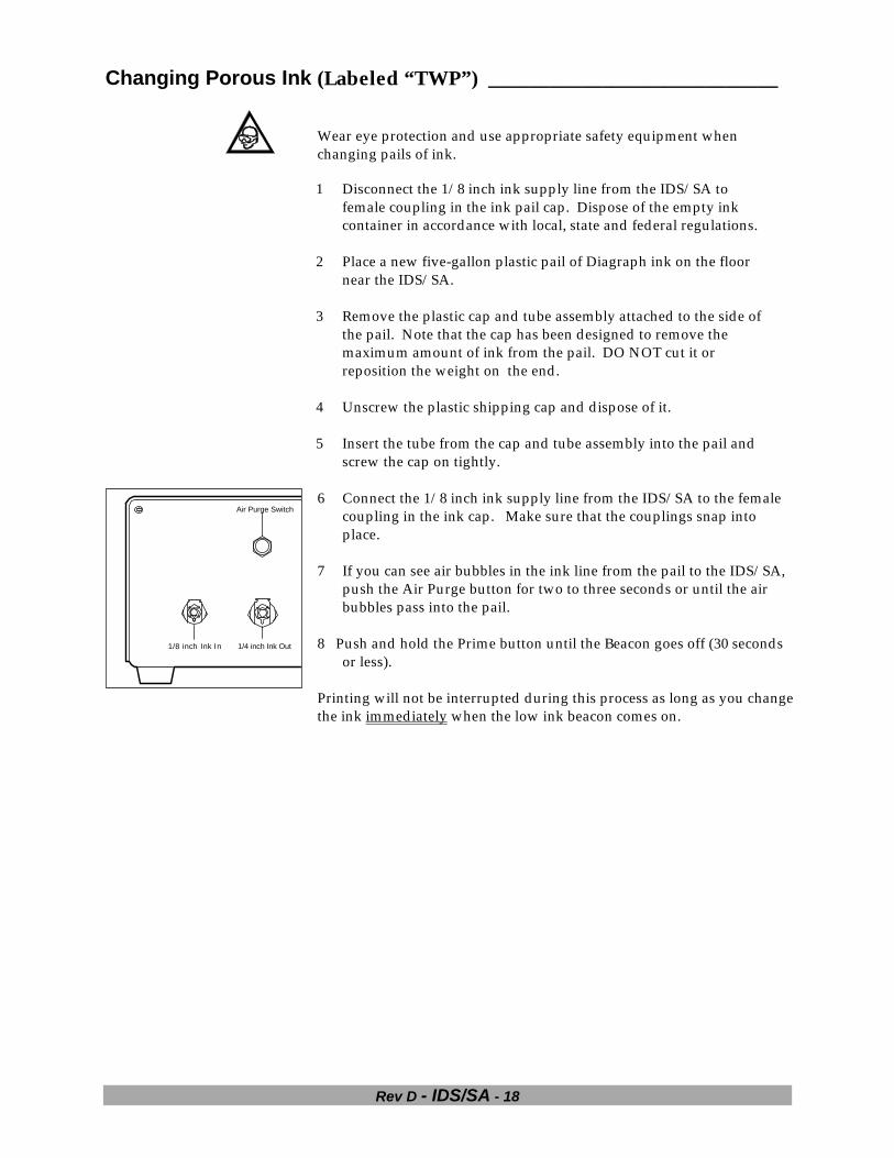
Air Purge Switch
1/4 inch Ink Out1/8 inch Ink In
6 Connect the 1/8 inch ink supply line from the IDS/SA to the femalecoupling in the ink cap. Make sure that the couplings snap intoplace.
7 If you can see air bubbles in the ink line from the pail to the IDS/SA,push the Air Purge button for two to three seconds or until the airbubbles pass into the pail.
8 Push and hold the Prime button until the Beacon goes off (30 secondsor less).
Printing will not be interrupted during this process as long as you changethe ink immediately when the low ink beacon comes on.

Rev D - IDS/SA - 19
Ink Regular Maintenance _____________________________________
If you see dot sizes fluctuating from time-to-time that correlate toincreases and decreases in the ink pressure (as measured with aDiagraph pressure gauge), your ink regulator may be in need ofmaintenance. Dot diameters will decrease when the ink regulatorinput pressure is less than 2.0 PSI greater than its adjusted outputpressure. Be sure always to supply at least 2.0 PSI more pressure tothe ink regulator than you need for the printhead in use.
Decreases may also be caused by obstructions in the valve seat of theink regulator. Sometimes, obstructions in the valve seat can cause thepressure to creep up over a fifteen minute period of time. Forexample, you may set the pressure to 5.0 PSI only to find fifteenminutes later, that it has increased to 7.0 PSI.
In either case, the following maintenance procedure can removeobstacles from the valve seat area of the ink regulator, restoringnormal operation:
1 Unplug the ink regulator from the printhead. (You may use ink,but conditioner is preferred for this procedure.)
2 Plug the ink regulator into an effluent bottle.
3 Rotate the regulator pressure adjustment clockwise until it stops,then counterclockwise until it stops. Repeat this six to twelvetimes.
Monitor the level of fluid in the effluent bottle to ensure it doesnot run over during this procedure.
4 Set the ink regulator off (completely counterclockwise), thenplug it back into the printhead.
5 Connect the Pressure Gauge to the printhead fluid exit.
6 Increase the ink flow until you reach the desired pressure.
7 Monitor the ink pressure while the printhead is printing. Notethat the gauge drops as much as 0.75 PSI (usually less) duringthe print cycle.
8 Increase the ink pressure such that the nominal printheadpressure is centered within the deflection of the gauge whileprinting.
9 Check the pressure fifteen minutes after setting it. It should bewithin the same range ± 0.5 PSI. If it is not, repeat the procedure.If you have already repeated the procedure, the regulator shouldbe replaced.

Rev D - IDS/SA - 20
Fan Filter Replacement
Replace the fan filter at least once a year or more frequently.As a guide, replace it whenever it is covered with dust.
Make sure that the IDS/SA is unplugged and in an area freefrom contaminants to change the filter.
Pry loose the plastic filter cover, remove the old filter andinsert a new one from the IDS/SA Spare Parts Kit.
Discard the old filter.

Rev D - IDS/SA - 21
TROUBLESHOOTING THE IDS/SA 4
Be sure to wear the appropriate safety equipment as prescribed by yoursupervisor when troubleshooting or operating this equipment.
ERROR CONDITIONS ________________________________________When the IDS/SA encounters an error condition, it will respond byturning off the pump, flashing the status LED and illuminating thelow ink beacon.
The following error conditions produce error reporting:
• The fuse for the fan has blown. Note its location in theillustration at left.
• The accumulator failed to reach the minimum pressure positionwithin approximately 30 seconds after the PRIME button waspushed.
• The accumulator remains between the medium and maximumpressure points for approximately 40 seconds during a pumpon condition.
For continued, satisfactory performance of the IDS/SA, take promptaction when you become aware of error reporting.
Note that you cannot eliminate the error without turning the unitOFF and then ON again. Prompt action will prolong the useful life ofthe pump
INDICATION SIGNALSThe chart below identifies the signal combinations for the status LED onthe front panel and the low ink beacon and explains what thesecombined signals mean.
LED BEACON INDICATION ACTIONOFF OFF Unit is OFF. The system is OFF. Power ON to begin
operation.ON Flashing IDS/SA is ON and the ink is LOW. Verify that the ink container is empty and
replace it with a full one of the same kind ofink. See the Changing Ink Containerssection.
ON OFF IDS/SA is ON and the inkaccumulator is pressurized
None. The IDS/SA is working to itsspecifications.
Flashing Flashing Error Condition Check Troubleshooting Section for diagnosesand remedies.

Rev D - IDS/SA - 22
Troubleshooting
ProblemType Problem Possible Causes Corrective ActionsElectrical You receive a shock from
the metal housing of theIDS/SA.
Incorrectly wired walloutlet.
Unplug the unit immediately andcheck the wall outlet with an outlettester. If the tester indicates incorrectwiring, contact plant maintenance andrequest a wiring change.
Frayed or damaged powercord.
A frayed or damaged powercord can cause electricalshock
Cord damaged by collisionor mishandling.
Do not touch the damaged cord andnotify your supervisor immediately.Do not leave the frayed or damagedpower cord unattended.
Fan The fan has stopped. 1 Unit is unplugged. Check the power cord and make surethat the wall outlet is live, and thepower cord is plugged into the walland firmly pressed into the powermodule.
The fan has stopped. 2 The power moduleswitch is OFF.
Turn the power module switch ON.
3 A blown fuse in thepower module.
Unplug the IDS/SA, remove the fusesin the power module and, using anohmmeter, replace all that read > 1.0� (5700-748).
4 The blown micro-fuse onthe controller board.
Unplug the IDS/SA, remove the coverand replace the micro-fuse (5700-369)on the controller board, if it reads > 1.0� on an ohmmeter.
5 The fan motor hasburned out.
Contact Diagraph at 1-800-526-2531 fora replacement fan assembly, Diagraphpart number 5700-765.

Rev D - IDS/SA - 23
ProblemType Problem Possible Causes Corrective ActionsLeak Ink leaks from the
couplings mounted in theIDS/SA.
It is unsafe to operate theIDS/SA with ink leaking.
Broken or worn fittings. • Turn the unit OFF andunplug power cord.
• Disconnect the ink inlet at theunit.
• Connect the effluent bottle tothe printhead ink line todepressurize the system.
• Disconnect the effluent bottlewhen ink stops flowing.
• Loosen the cover screws andremove the stainless coverfrom the unit.
• If internal leakage isobserved, see the followingpage on troubleshootinginternal leaks.
• If source of ink leakage isapparent, replace the affectedcomponents.
• If source of ink leakage is notapparent, check to see if thecouplings for ink input oroutput require replacement.
• If the source of ink leakage isnot apparent, contactDiagraph at 1-800-526-2531for exchange or replacement.
Leak Ink container is leaking. Container has beenpunctured during shippingor handling.
Contain ink seepage using theappropriate spill hazard kit asprescribed. Review the ink’s MSDSand dispose of in accordance withlocal, state, and federal regulations.Contact Diagraph for replacement ink.

Rev D - IDS/SA - 24
ProblemType Problem Possible Causes Corrective ActionsLeak Ink is leaking from inside
the IDS/SAInternal damage. • Turn the unit OFF and unplug
it from the wall.• Disconnect the ink inlet at the
unit.• Connect the effluent bottle to
the printhead ink line todepressurize the system;disconnect the effluent bottlewhen ink stops flowing.
• Disconnect the ink output tothe printheads from the unit.
• Loosen the cover screws andremove the stainless coverfrom the unit.
• If the source of ink leakage isapparent, look into replacingthe affected components. Allcomponents identified in the
A - Elbow (6105-149)B - Tubing (1301-875)C - Elbow (6105-149)D - Accumulator (5700-902)E - Manifold (5700-888)F - Check Valve (5700-738)H - Coupling (5700-561)I - Tubing (1301-875)J - Elbow (6105-149)K - Elbow (6105-149)
L - Hose Barb (5700-160)M - Elbow (5700-889)N - Fitting (1902-260)O - Push Button Valve
(57800-737)P - Connector (1199-158 &
1199-160)Q - Pump (5700-098)R - Tubing (1301-468)S - Coupling (1900-758)
drawing at left are replaceableexcept for the accumulator.
• If the source of ink leak is notapparent or if theaccumulator is leaking,contact Diagraph at 1-800-526-2531 for service orexchange.
Leak Regulator is leaking. 1 Body or fittings areloosened.2 Broken component.
• Disconnect the ink outlet tothe printheads from the unit.
• Connect the effluent bottleto the printhead ink lines todepressurize the system.Disconnect the effluentbottle when no more ink isflowing.
• Disconnect the ink regulatorfrom the printhead andprinthead ink main line.
• Examine the ink regulator tosee if the body coupling istight. If it is not, it should behand tightened.
(Continued on next page)

Rev D - IDS/SA - 25
ProblemType Problem Possible Causes Corrective Actions
• Determine if any cracking ofthe body or loose tubingfittings are responsible.
• If any physical damage isobserved, contact Diagraph at1-800-526-2531 for exchangeor replacement.
• If the tubing fitting is leaking,remove the tube and clean thefittings using the appropriateconditioner. Use a pair ofdiagonal cutters to removeabout 1 inch of tubing, ensurea good square cut.
• Reconnect the tubing to theregulator and be sure allcomponents are dry and cleanbefore reassembling. Fittingsshould be hand tightened.Perform ink regulatormaintenance procedure afterbefore using the part.
Light Beacon not working. Beacon not connected Check cable between beacon and unitto ensure it is connected securely andthat no damaged connectors areresponsible.
Beacon not illuminatedwhen the LED is flashing.
Beacon lamp is burned out. Replace the lamp in the beacon. Notethat the red plastic dome of the beaconis friction-fitted and VERY difficult toremove.
Beacon is flashing but theLED is not lit.
LED is burned out. Unplug the IDS/SA and replace it withan LED assembly (5700-763) from theSpare Parts Kit.
No lights (beacon or LED). Unit is unplugged. Check the power cord and make surethat the wall outlet is live, and thepower cord is plugged into the walland firmly pressed into the powermodule.

Rev D - IDS/SA - 26
ProblemType Problem Possible Causes Corrective ActionsLight No lights (beacon or LED). A fuse in the power module
has blown out.Unplug the IDS/SA, check the fuses inthe power module and replace all thatare burned out.
Noise Intermittent noise frominside the IDS/SA.
Pump is loose. Disconnect power cord.Remove cover and tightenpump mounts.
Intermittent noise frominside the IDS/SA.
Accumulator is defective. • Set run/idle switch to idleand unplug unit from wall.
• Disconnect ink input fromcontainer at unit.
• Connect effluent bottle toprinthead line to depressurizeink supply; disconnecteffluent bottle when ink stopsflowing.
• Disconnect ink output toprintheads at unit.
• Contact Diagraph at 1-800-526-2531 for service orexchange.
Operation Unexpected shutdown. 1 Slow ink leak (external) Determine source of ink leakage andrefer to the appropriatetroubleshooting procedure forcorrective action.
2 Low line voltage Check line voltage at outlet. Voltageshould not be <90 VAC.

Rev D - IDS/SA - 27
ProblemType Problem Possible Causes Corrective ActionsOperation Dot sizes too small, unable
to achieve required inkpressure.
1 Too many printheads
2 Ink flow path obstructed
Do not exceed the maximum numberof printheads per the table below: Printhead Printhead
Size Max #1/2” 127/8” 82” 4Barcode 4
If you are mixing printhead sizes, one7/8” equals two 1/2” or one 2”; abarcode = three 1/2”.
Check the ink line for sharp bends.Make sure no objects are sitting on theline or pinching it.
Pump IDS/SA will not empty theink pail.
Ink cap installedincorrectly.
Repeat installation instructions.
Pump does not cycle on. Pump is defective(IDS/SA ReplacementPump Assembly Kit #5700-992)
• Turn unit OFF and unplug fromwall.
• Disconnect ink input fromcontainer at unit.
• Connect effluent bottle toprinthead line to depressurize inksupply; disconnect effluent bottlewhen ink stops flowing.
• Disconnect ink output toprintheads at unit.
• Loosen the four screws securingthe cover to the unit.
• Follow pump replacementprocedure in Appendix A.
IDS/SA will not empty theink pail.
Ink cap installedincorrectly.
Repeat installation instructions.
Unit does not prime afterfollowing the priminginstructions.
The IDS/SA sits too farabove the pail and the pumpcan not draw ink up to thatheight.
Elevate the ink pail so a positivepressure occurs from the pail to theIDS/SA. Run the Priming procedureagain.

Rev D - IDS/SA - 28
ProblemType Problem Possible Causes Corrective ActionsPriming The Prime button does not
respond after holding itmore than thirty seconds.
A time-out has probablyoccurred on the controller.
Reset the Prime button by switchingthe mode switch from ON to OFF andback to ON. The Prime button shouldagain be active.
The priming goes onbeyond 15 seconds.
1 Punctured ordisconnected inkline.
2 Flow path obstructed.
Unplug the IDS/SA and disconnectthe ink out tube. Check immediatelyfor the ink leak location. Repair theink line break and reconnect theIDS/SA.
Check the ink line for sharpbends. Make sure no objectsare sitting on the line orpinching it.

Rev D - IDS/SA - 29
IDS/SA Parts & Inks 5
Spare Parts Kit (5700-778) ____________________________________
Qty Part Number Part Type Notes5 5700-870 Fan Filter Media Replacing this filter is a simple operation:
pry loose the plastic filter cover, removethe old filter and insert a new one. Makesure that the IDS/SA is unplugged and inan area free from airborne contaminantswhen changing the filter.
2 5700-748 MDL-2 Fuse 250V, 2A
Replacing these fuses requires a smallblade screwdriver both to pry open thepower module cover and to pop out thetray that holds the fuses. Pay closeattention when returning the fuse traywith new fuses to orient it to the correctpower configuration, 115V or 230V. Andbe sure to push the power module coveruntil it snaps closed completely.
2 5700-369 Fuse 125V, 315 mA
This micro-fuse only powers the fan.Unplug the IDS/SA and remove thestainless steel cover to replace this fuse onthe controller board.
1 5700-763 P3 Cable / Panel LED Assembly
Replacing this assembly requiresremoving the stainless steel cover. Besure to disconnect power beforeremoving. The two-pin connector for theLED is the only one inside the IDS/SAand is located on the front edge of thelogic board.
1 5700-776 Beacon Lamp
Accessing the beacon lamp consistssimply of removing the red plastic beaconcover. This cover however fits VERYtightly and will require considerable effortto remove it. Take care not to crack thecover when removing and replacing thelamp.

Rev D - IDS/SA - 30
INKS ______________________________________________________
Wear safety goggles whenever working with ink or ink supply lines. Checkwith your supervisor for additional safety directives.
Diagraph supplies three kinds of ink jet sytem inks: porous, non-porous andpigmented. DO NOT USE PIGMENTED INK IN THE IDS/SA. Use ofpigmented ink will void all warrenties, expressed and implied. It is built foruse only with porous and non-porous varities.
Compatible Inks
The Diagraph inks identified in the table below have beentested and approved for use in the IDS/SA.
USE ONLY LISTED INKS. Untested inks could impair the operationof the IDS/SA and possibly cause permanent damage.
Diagraph InkOne GallonContainer
Five GallonContainer
30 GallonContainer
TWP-1 Black 2600-306A 2600-305 2600-912A
TWP-2 Red 2600-309 2600-308
TWP-3 Green 2600-311 2600-310
TWP-4 Bright Blue 2600-317 2600-316
TWP-5 Purple 2600-292 2600-291
TWP-6 Yellow 2600-284 2600-283
TWP-8 Bright Orange 2600-296 2600-295
TWP-9 Brown 2600-288 2600-287
TWP-GB Black 2600-315 2600-314
TWP-GB Blue 2600-272 2600-271
TWP-WR Black 2600-313 2600-312
TWP Conditioner 2600-252 2600-251
Diagraph will be adding more inks to this list so checkwith your Field Sales Representative to keep informedabout new inks, new colors and extended capabilities.

Rev D - IDS/SA - 31
Appendix A - Replacing the Pump
Tools & Materials Replacement pump kit (Part # 57 00-992)Effluent bottleDisposable dry wipesTFE tape or pipe joint compound3/8 inch socket wrenchXacto knife
Always wear safety goggles when working with pressurized liquidsystems.
Open the IDS/SA pump replacement kit and identify all components.If any parts are missing or were damaged in shipping, contactDiagraph Service.
① Tubing connection to purge switch ⑤ 1/8” ID tubing to manifold elbow② Coupling to ink container ⑥ Check valve for INK OUT port③ Molex connector to transformer ⑦ Ink filter④ 24 Volt AC Pump ⑧ Coupling to IDS/SA INK IN port
■ Removing the Faulty Pump1 Unplug the IDS/SA power cord.2 Connect the effluent bottle to the Ink Out port and wait for the
accumulator to depressurize.3 Remove the cover.4 Disconnect the two pin Molex connector from the pump to the
transformer and remove the connector from the housingpartition.
5 Remove the four nuts holding the pump to the base with the 3/8inch socket wrench. Set aside the nuts.
6 Fold a dry wipe and place it under the 1/8 inch fitting on theinput side of the pump.

Rev D - IDS/SA - 32
7 Using diagonal cutters, cut the 1/8 inch ID tubing connected tothe input side of the pump.
8 Press the wipe around the severed tubing to absorb any ink9 Roll a fresh wipe and place it under the elbow fitting on the
output side of the pump.10 Position the IDS/SA so that the electrical compartment is closest
to you. This repositioning allows you to closely observe the nextstep and to gain leverage for cutting tubing.
11 Using the Xacto knife, cut the tubing between the elbow fittingon the output side of the pump and the elbow fitting on themanifold. Cut toward the metal partition to avoid an accidentalpuncture.
12 When the tubing is cut through, press the wipe around the cut toabsorb leaking ink.
13 Remove the faulty pump from the housing.14 Use another clean wipe and clean up any drips.15 Using diagonal cutters, carefully nibble away the tubing that
remains on the manifold elbow fitting. Take care not to cut orscar the fitting. Clean with a wipe when complete.
16 Using diagonal cutters, carefully pinch and pull the 1/8 inch IDtubing from the fitting on the air purge valve. Take care not tocut or scar the fitting. Clean with wipe when complete.
■ Installing the New Pump1 Place the new pump in position.2 Use TFE tape or pipe joint compound on the threads of the
elbow on the manifold and slide on the tubing from the outputside of the pump.
3 Use TFE tape or pipe joint compound on the threads of the malefitting on the purge switch and slide on the tubing from theinput side of the pump.

Rev D - IDS/SA - 33
4 Fit the two pin Molex connector from the pump into the openingin the partition housing and reconnect to the transformer.
5 Secure the pump to the housing with the nuts set aside in step 66 Reconnect ink lines and with the effluent bottle at the end.7 Turn on system power.8 Press the prime button: you should hear the pump start. If it
does not, unplug the power cord and check the Molex connectorto transformer.
9 Hold the prime button until the air evacuates the line and inkruns into the effluent bottle.
10 Release the prime button and disconnect the effluent bottle.11 Terminate the end of the ink line.12 Press the prime button until the system comes up to pressure.13 Replace the system cover.

Rev D - IDS/SA - 34
Appendix B – Air Purge Valve RemovalOlder units of the IDS/SA have an air purge valve. This air purge valve hasbeen removed from the newer IDS/SA.
IDS/SA without the air purge valve:The operation of the IDS/SA has not been affected by the removal ofthe air purge valve.
Connections………………..On the newer units the ink-input line connects directly to the inputside of the pump. The output side of the pump connects to a Tfitting, which is then connected to the accumulator and the inkoutput. Appendix A (Replacing the Pump) guides you towardmaking connections to the air purge valve, ignore these instructionsand make the connections per the below figure.
A – Elbow (6105-149)B – Accumulator (5700-902)C – Coupling (5700-561)D – Coupling (1900-758)F – Pump (5700-098)G – Hose Barb (5700-160)H – Tubing (1301-468)J – T fitting (5700-562)K – Tubing (1301-875)M – Connector (1199-158 &
1199-160)N – Check Valve (1902-307)O – Elbow fitting (5361-309)
Air bubbles………………….There are two places in the manual that refer to using the air purgevalve to remove bubbles from the ink line. Tests have proven that theair bubbles are not removed by the air purge valve. They can only beremoved by priming the system per the instructions in the manual.
IDS/SA with the air purge valve:If you have an older IDS/SA and are not experiencing any problemswith the air purge valve, we advise that you leave it in place ratherthan remove it.