Embed Size (px)
Citation preview

MANUAL
INSTALLATION OPERATION MAINTENANCE
REFRIGERATED COMPRESSED AIR DRYER
Coldspell Series
PDF processed with CutePDF evaluation edition www.CutePDF.com

.

This document may be modified without noticereproduction, even partial, forbidden without written authentication 1
Contents
1. Introduction 2
1.1 Design
1.2 Description
2. Specifications 2
Operational Details
3. Operating Principle 3
3.1 Pneumatic Section
3.2 Refrigeration section
3.3 Safety
3.4 Schematic Diagrams
4. Electrical 6
4.1 Bar Indicating Controller - Operation / Setting
4.2 LCD Controller - Operation / Setting
4.3 Wiring Diagram
5. Installation 13
5.1 Storage
5.2 Installation and Site Connections
5.3 Electrical Connections
5.4 Running the Installation
6. Operation 14
6.1 Operator
6.2 How to stop the Dryer
7. Maintenance 15
8. Condenser Cleaning 16
8.1 Air cooled condenser
8.2 Water cooled condenser
9. Amount of Gas to be charged 16
10. Repair Work 17
11. Recommended spares list for 5 years 20

INSTRUCTION MANUAL - Coldspell
Reference : Manual Version 22
READ THIS MANUAL CAREFULLYBEFORE INSTALLING OR OPERATING THE EQUIPMENT
These symbols warn you of any dangers and the measures to be taken to prevent them.
The most important points for the correct operation of your dryer are printed in bold.
1. Introduction
1.1 Design
Coldspell refrigeration dryer eliminates any water vapour remaining in the compressed air coming at the outlet of thecompressor house. The dryers have been designed for nominal standard inlet conditions as per ISO 7183 in order toobtain a dew point under pressure of +3oC to +7oC.
1.2 Description
The dryer consists of :
l Integrated Heat Exchanger
l Refrigerant Compressor
l Electronic controller
l Condenser Assembly
l Expansion Device
l Pressure switch*
l Refrigerant Suction & Discharge Pressure Gauges
l Hot gas bypass valve
l Auto drain valve
l Canopy
2. Specifications
Operational Details
Medium : Compressed Air
Inlet condition : Free of dirt, oil, condensate and corrosive substances.
Operating pressure* : 7 Kg/cm2
Inlet temperature* : Max +45oC
Inlet humidity : Saturated at specified conditions
Ambient temperature : Max +38oC
Pressure dew point : + 3oC to 7oC
Cooling system : Air cooled / Water cooled
Max. Working pressure : 16 Kg/cm2
Refrigerant compressor : Hermetic sealed
* Optional
!

This document may be modified without noticereproduction, even partial, forbidden without written authentication 3
3. Operating Principle
3.1 Pneumatic section
The moist compressed air (dirt, oil and water vapor) enters into the Air/Air section of Integrated Heat Exchanger whereit is precooled by the outgoing air and thereby conserving energy.
The compressed air next passes through the evaporator section of Integrated Heat Exchanger. It is cooled up to +3oCby the Refrigerant. At this sub-cooled temperature, the moisture present in the air is condensed and removed bythe Demister section of Integrated Heat Exchanger.
The cool saturated air passes through the Air to Air section of Integrated Heat Exchanger where it precools incomingair and gets heated up. Thus, this system provides clean dry air at the outlet. Efficient Filter and Automatic DrainValve carry out the removal of moisture at Demister. The Integrated Heat Exchangers are designed in such a waythat they are self-cleaning to maintain constant heat transfer rate.
3.2 Refrigeration section (Freon)
The Evaporator removes heat from compressed air by means of cold and low pressure freon. The heat removed fromthe system is dissipated to the atmosphere/water by the condenser. The high pressure refrigerant flows into theexpansion valves where it changes into liquid phase at low pressure. The boiling of liquid refrigerant takes place inthe Evaporator and cold air leaves the Evaporator. The low pressure, low temperature refrigerant passes into thecompressor and the cycle repeats.
The Refrigeration Dryer senses the refrigerant suction pressure and accordingly varies the flow of hot gas bypass insidethe system and maintains constant dew point at various heat loads.
3.3 Safety
Pressurised equipments may explode if used improperly. It is therefore essential to locate anypressurised equipment, in such a way that the risks relating to incorrect use are reduced to theabsolute minimum.
The person responsible for the staff who are going to install, operate and maintain the machines described in thismanual must make sure that they have read and understood these instructions.
In particular, we draw your attention to the safety procedures which are described in this manual and which must bescrupulously adhered to. Observing these measures will allow you to install, operate and maintain your dryer withoutrisk.
Coldspell dryers are intended for drying of compressed air. Under no circumstances should they be used to dry othergases before Trident has performed a preliminary study and provided special instructions.
!

CS TID 20 - 250 P & I DIAGRAM
4
3.4 Schematic Diagrams
CS TID 300 - 500 P & I DIAGRAM
INSTRUCTION MANUAL - Coldspell
Reference : Manual Version 2
REFRIGERANT LINE
AIR LINE
ELECTRICAL LINE
IN
AIR
ADV
OUT
AIR
INTEGRATED HEAT EXCHANGER
DEMISTERPRE BALANCE LINE
FREON
DRYER
HOT GAS
BYPASS VALVE
EXPANSION DEVICE
HP/LP
REF. COMPRESSOR
EV
AP
OR
AT
OR
A
IR/A
IR
HE
AT
EX
CH
AN
GE
R
PROBE
Expansion valve
bulb
DISCHARGE
PRESSURE
GAUGE
PS
1

This document may be modified without noticereproduction, even partial, forbidden without written authentication 5
CS TID 650 - 2000 P & I DIAGRAM

6
4. Electrical
4.1 Bar Indicating Controller - Operation / Setting (Used upto model CS800)
Dryer ON/OFF:
The Air Dryer is switched ON/OFF using Dryer ON/OFF switch. The moment Dryer is switched ON, built in Anti-Recyclingtimer delays the Dryer switching ON by 2 minutes. After 2 minutes Refrigerant Compressor and Condenser Fan switchesON and Dryer starts functioning.
Status Indication:
The Status Indication LCDs shows Drain valve, Hot Gas By-Pass Valve & Compressor ON/OFF.
Dew point Indication:
The dryer dew point temperature is displayed in deg. C by default in increments of 2, starting from 2 deg C.
Safety Feature for Low Dew point:
The Controller comes with Built in Low dew point setting of 0oC, the moment dew point temperature reaches thislower level, the controller switches OFF the Refrigerant Compressor. After 2 minutes if the dew point temperature isgreater than 0oC, refrigerant compressor switches ON automatically.
Refrigeration Dryer
2 6 8°C
S 2 6 84 10
DRAIN
HOT GAS
COMPRESSOR
MANUALDRAIN
0
1
Dew point temperature Display in C (default)o
Drain ON time/HGBPV ON temperature setting display (Seconds/ C
o)
Drain ON time setting
Manual Drain Switch
Hot Gas By-Pass Valve ON temperature setting
Dryer ON/OFF SwitchStatus Indication
INSTRUCTION MANUAL - Coldspell
Reference : Manual Version 2

This document may be modified without noticereproduction, even partial, forbidden without written authentication 7
Manual Drain:
The drain valve can be manually switched ON by pressing the Manual Drain Switch. The Drain Valve will be ON till theManual Drain Switch is released after pressing.
Drain ON time setting:
The drain valve ON time (opening period) can be set,by pressing drain ON time setting button as shown infigure, pressing once will show the current setting inseconds in the display, pressing again will shift the timein increments of 2 seconds, and can be seen in DrainON time setting display in seconds. Drain valve cycleson a fixed time of 2 minutes. The moment Drain ONtime setting switch is released, after few seconds thedryer display returns to normal function.
Refrigeration Dryer
2 6 8°C
S 2 6 84 10
DRAIN
HOT GAS
COMPRESSOR
MANUALDRAIN

8
4.2 LCD Controller - Operation / Setting (For CS1000 and above)
Introduction:
The controller is used in Coldspell models from CS 1000 and above. The controller default display is dew pointtemperature, Inlet temperature of the compressed air, Compressor running hours.
Available Keys:
I/OMENUUPDOWN
l Default display is dew point temperature, inlet temperature of the compressed air.l Compressor running hours are displayed at the right bottom corner of the display.
Menus available:
1. Drain valve ON/OFF cycle settings.3. Compressor offset temperature settings.
How to ON/OFF the Dryer:
l Press I/O button for one second to ON thedryer/controller.
l The Refrigeration compressor will switch ON after2 minutes due to Anti Recycle Timer.
l If the compressor trip occurs, the refrigerationcompressor will switch ON after 2 minutes.
l Press I/O button for two seconds to switchOFF the dryer/controller.
Menu Setting:
l To move from one menu to other, press MENUkey.
l Press up & down keys to increase or decreasesetting valves.
Features In Front Panel:
l Compressor ON
l Drain valve ON
l Anti Recycle Delay
INSTRUCTION MANUAL - Coldspell
Reference : Manual Version 2

This document may be modified without noticereproduction, even partial, forbidden without written authentication 9
4.3 Wiring Diagram
CS TID 40-60 - Wiring Diagram
CS TID 20 - Wiring Diagram

10
INSTRUCTION MANUAL - Coldspell
Reference : Manual Version 2
CS TID 80 - 100 - Wiring Diagram
CS TID 150 - Wiring Diagram

This document may be modified without noticereproduction, even partial, forbidden without written authentication 11
CS TID 200 - 250 - Wiring Diagram
CS TID 300 - 500 - Wiring Diagram

12
INSTRUCTION MANUAL - Coldspell
Reference : Manual Version 2
CS TID 650 - 800 - Wiring Diagram
CS TID 1000 - 2000 - Wiring Diagram

This document may be modified without noticereproduction, even partial, forbidden without written authentication 13
Series-ColdspellRefrigeration Dryer
TRIDENT
5. Installation
Various risks (crushing, explosion, projection, noise,…): The installation operations described in thischapter should be performed only by personnel qualified in the installation of electro-pneumaticsystems. Follow the procedure described below with care in order to prevent exposing personnel todanger.
5.1 Storage
If your dryer is to be stored for a long time before installation and use, follow these instructions.
l If possible, let the dryer remain in its original packing (In particular, products fitted with marine packing withplastic film and dessicant).
l Check that air inlet and outlet are properly blocked in order to protect the system from foreign materials.
l Check that the machine is properly protected from atmospheric dust or water.
l Check that the store is frost protected.
l Make sure to archive correctly the attached documents.
5.2 Installation and site connections
1. Install the dryer in a closed, clean and dry room protected from frost. Access to the room should be restrictedto personnel not qualified in unit maintenance and operation. The room must be adequately ventilated. Thedryer must not be directly exposed to sources of heat. The temperature of the room must not exceed 38oC.
2. Make sure that the dryer is not near any equipment which does not comply with the electromagneticcompatibility directives and which may degrade dryer operation. There must be a minimum distance of 1 mbetween the dryer and any other equipment, which uses electricity. Yellow lines demarcating the area arepreferred.
3. Ensure that the dryer is installed in vertical position and kept level.
4. Fix the anchor points if necessary.
5. Install a system of by-pass valves between the dryer inlet and outlet so as to be able to service the installationwithout having to interrupt the compressed air supply from the network. The upstream and downstream valvesmust be closed during installation.
6. Connect the compressed air for processing to the dryer inlet with rust-free pipes.
7. Connect a drain pipe to the drain valve part connection (½''F)
!

14
8. Connect the processed compressed air to the dryer output with rust-free pipes.
9. Check that all the connectors are airtight and that the fittings are tight.
5.3 Electrical Connections
Connect the electrical power cable to the supply as specified in this manual, ensure the supply is well grounded.
Risk of electrical shock: When connecting the machine, cut off the power at the connecting point.
5.4 Running the installation
Various risks (explosion, projection, noise, ...): Do not pressurise until the installation procedurehas been completed.
For water-cooled condenser, ensure that the Water pump is switched on.
Switch ON the system with the ON/OFF switch provided in the front panel of the canopy.
6. Operation
6.1 Operator
Only a minimum level of experience in handling compressed air is necessary to operate a Coldspell refrigeration dryer andhe should be familiar in the following terminologies :
l Pressure in Kg/cm2
l Flow in cfm
l Dew points in oC
l Components of a fluid network: compressor, valves, drains, taps, pressure gauges, filters, tanks,...
6.2 How to stop the dryer
Various risks (projection, explosion, noise,...) : Whenever working on the dryer, it I esessentialto disconnect it from the network. Follow the procedure below :
1. Open the by-pass valve
2. Close the upstream valve
3. Close the downstream valve
4. Switch off the Dryer
5. Vent the air inside the dryer
!
!
!
INSTRUCTION MANUAL - Coldspell
Reference : Manual Version 2

This document may be modified without noticereproduction, even partial, forbidden without written authentication 15
7. Maintenance
Various risks (projection, noise, ...) : This operation should be performed by professionals ofRefrigeration.
Trident make Refrigeration dryers are robust, reliable machines. To ensure uninterrupted, problem-free operation, regularlyperform the inspections below.
Type of Discharge Drain Air Cooled Water Inlet Dew pointinspection pressure valve condenser cooled temper- temper-
in refrigerant surface condenser ature atureline cleaning cleaning
using diluteHCL
Visual D D W Y D D
Sparesreplacement - - - - - -
Cleaning - H/R M Y/R - -
D - Daily W - Weekly M - Monthly H - Half Yearly Y- Yearly R - As required
* Note : For water cooled condenser clean the condenser by recirculating dilute HCl if discharge pressure exceedsthe value specified in Table 7.1.
Table 7.1
Freon Discharge pressure in psig
R134a 160-200
R407c 240-320
!

16
8. Condenser cleaning
8.1 Air Cooled
l Switch OFF the dryer
l Open the side doors, so that all dust removed while cleaning can be vented out of dryer through the side doors.
l Using compressed air and an air gun clean the dust accumulated on the condenser fins from outside the dryer.
l Ensure that there is no dust inside the dryer and reassemble the doors.
8.2 Water Cooled
l Switch OFF the dryer
l Stop the water supply and close the inlet and outlet valves of the water supply
l Open the door covering the condenser.
l Drain the water completely.
l Pass dilute HCl solution in the tube side at pressure for more than 1 hour
l Reassemble all and switch ON the dryer.
9. Amount of Gas to be charged
Sl. No. Model Refrigerant Quantity of refrigerantto be charged (in Kg)
1 20 R134a 0.52 40 R134a 0.753 50/60 R134a 0.754 80 R134a 1.05 100 R134a 1.06 150 R134a 1.47 200 R134a/R407C 1.9/2.28 250 R134a/R407C 1.9/2.29 300 R134a 3.2
10 400 R134a 3.411 500 R134a 3.712 650 R407C 7.013 800 R407C 7.214 1000 R407C 8.315 1250 R407C 9.016 1500 R407C 10.517 2000 R407C 11.0
This is for information only. If in doubt, contact Trident.
INSTRUCTION MANUAL - Coldspell
Reference : Manual Version 2

This document may be modified without noticereproduction, even partial, forbidden without written authentication 17
1. Loose Wiring Connections2. Phase Preventer Trip (3 phase models)3. Fuse Blown(3phase models)4. Dryer ON/OFF switch failure.
1. Compressed air to the dryer IN/OUTinterchanged.
2. Air Flow to the dryer exceeds its rated flow.3. Ice formation happens at the Air path inside
the heat exchanger due to freezing.4. Drain Valve Clogged.5. Heat Exchanger Clogged.
1. Excess water enters at the dryer inlet thanspecified.
2. Drain Valve(Heat Exchanger) not working.3. Excess load given to dyer than its rated
specifications.4. Air line bypass valve partially open.5. Refrigeration Compressor not working.
1. Excess load to dryer than rated.2. High Suction Pressure.3. Refrigerant charge quantity is insufficient.4. High Superheat setting on the expansion valve.5. Temperature probe malfunction.
1. Low load to dryer.2. Low Suction Pressure.3. Low superheat setting on the expansion valve.4. Temperature probe malfunction.
Trouble Root cause Solution
1. Correct the wiring.2. Check the input voltage,phase
reversal.3. Replace the fuse4. Replace the Switch
1. Make the connections correctly.2. Operate the dryer below its rated load.3. Increase the suction pressure of the
refrigerant.4. Clean the drain valve.5. Flush the Heat Exchanger with
compressed air.
1. Ensure Air receiver tank with drainvalve installation before the dryer.
2. Check and repair the drain valve.3. Operate the dryer below the its rated
capacity.4. Completely close the bypass valve.5. Check and correct the compressor.
1. Operate the dryer below its ratedcapacity.
2. Reduce the suction pressure usingHGBV.
3. Charge sufficient quantity ofrefrigerant.
4. Reduce the superheat setting in theexpansion valve.
5. Replace the probe.
1. Operate the dryer below its ratedcapacity.
2. Increase the suction pressure usingHGBV.
3. Increase the superheat setting in theexpansion valve.
4. Replace the probe.
10. Repair work
Dryer not Switching ON.(No indications on thecontroller)
Air Pressure Drop (>0.3barg).[Across the Dryer]
Moisture carryover at thedryer outlet.
High Dewpoint Temperature(>7ºC)
Low Dewpoint Temperature(<3ºC)
GENERAL SECTION
REFRIGERANT SECTION
1. Charge the refrigerant with referanceto compressor current.
2. Operate the dryer below its ratedcapacity.
3. Adjust the HGBV setting to reduce thesuction pressure.
4. Clean the condenser coil surface.5. Replace the Heat Exchanger.
1. Refrigerant overcharge.2. Excess load to the dryer.3. Hot Gas Bypass Valve setting high.4. Condenser coil is clogged.5. Heat Exchanger Leak(internal).
High Suction Pressure&High Discharge Pressure

18
INSTRUCTION MANUAL - Coldspell
Reference : Manual Version 2
Trouble Root cause Solution
High Suction Pressure&Low Discharge Pressure
Low Suction Pressure&Low Discharge Pressure
Low Suction Pressure&High Discharge Pressure
Compressor takes High Current
Compressor takes Low Current
Compressor not starting.
Compressor trips on LPPressure switch
Compressor trips on HPPressure switch
1. Hot Gas Bypass valve setting High.2. HGBV failure(always remains open).3. Low Superheat setting.4. Compressor Pumping failure.
1. Refrigerant Charge quantity less.2. Expansion Valve bulb charge lost.
1. Hot gas bypass valve setting low.2. Filter drier partially/fully clogged.3. Expansion valve clogged.4. Heat Exchanger (Ref Side) clogged.
1. Voltage imbalance or higher voltage exists.2. Compressor relay,capacitor fails.3. Refrigerant not reaches its idle pressure be-
fore starting(R407C).4. Loose wiring.5. Compressor failure.
1. Refrigerant charge quantity very less.2. Compressor pumping failure
1. Loose wiring connection.2. External OLP trip due to overheating(1phase
models).3. Internal OLP trip due to overheating (3phase
models).4. Relay,Capacitor.OLP failure.5. Dewpoint Temperature lies between -3ºC to
0ºC.6. HP/LP Switch trip.
1. Low suction pressure setting in the HGBV.2. Trip pressure setting kept high in LP Switch.3. No refrigerant gas inside the system.
1. Adjust the HGBV Setting (increase).2. Replace the filter drier.3. Clean the expansion valve with dry nitrogen
and reuse.4. Flush the HX with dry nitrogen.If problem ex-
ists replace the HX.
1. Adjust the HGBV setting to reduce thesuction pressure.
2. Replace the Valve.3. Adjust the superheat setting(increase).4. Replace the compressor.
1. Charge sufficient quantity ofrefrigerant.
2. Replace the Expansion Valve.
1. Adjust the HGBV Setting(increase).2. Replace the filter drier.3. Clean the expansion valve with dry
nitrogen and reuse.4. Flush the HX with dry nitrogen.If
problem exists replace the HX.
1. Check and correct the voltage.2. Replace necessary compressor
accessories.3. Allow the refrigerant to reach its idle
pressure before the compressor starts.4. Correct the wiring.5. Replace the compressor.
1. Charge sufficient quantity ofrefrigerant.
2. Replace the Compressor.
1. Check and correct wiring.2. Allow the compressor body
temperature to cool until it reachesambient.
3. Allow the compressor bodytemperature to cool until it reachesambient
4. Replace5. Adjust the HGBV to increase the
dewpoint temperature to safe limit.6. Reset the switches.
1. Increase the Suction pressure usingHGBV.
2. Set the trip pressure correctly.3. Check and arrest the leak before
charging the refrigerant in the system.
1. Check and correct it.2. Replace the switch.3. Clean the condenser surface.4. Set the trip pressure correctly.

Trouble Root cause Solution
1. Compressor Internal winding overheated.
1. High current consumption by the compressor.2. Liquid floodback to the compressor(Lubrication
failure).
1. Loose wiring.2. Fan motor ronning capacitor failure.3. Fan motor failure.
1. Loose wiring connections.2. No input supply to the switch.3. Pressure switch failure.
1. Loose wiring.2. Wrong input supply.3. Transformer failure due to manufacturing de-
fect or higher voltage.
1. Clogging due to no installation of Prefilter atdryer inlet(Dust entrainment).
2. Coil failure due to input voltage of manufac-turing defect.
1. Loose Wiring.2. Inputs to preventer wrongly connected.3. Under voltage, Over voltage,phase reversal,
phase loss exists.4. Preventer problem.
1. Allow the compressor body to cool untilit reaches ambient temperature.
1. Check and correct it.2. Check and adjust the superheat setting
in the expansion valve.
1. Check and correct it.2. Replace the capacitor.3. Replace the fan.
1. Check and correct it.2. Check and correct it.3. Replace the switch.
1. Check and correct it.2. Check and correct it.3. Replace the Transformer.
1. Ensure prefilter before the dryer,if thedryer environment is dusty.
2. Replace the coil.
1. Check and correct it.2. Connect the inputs properly.3. Check and correct it.4. Replace the problem.
Compressor trips on OverLoad Protector(OLP) [compressor body too hot].
Compressor windingOverheated.
Condenser Fan not running
Pressure switches not working
Transformer not working
Drain Valve failure
Phase Preventer Trip
This document may be modified without noticereproduction, even partial, forbidden without written authentication 19

Reference : Manual Version 2
11. Recommended spares for 5 years trouble free operation
Recommended Spare List - CS TID 20 [PH191]
Sl.No Part No Description
1 CH113 Freon Drier 1/4”
2 CH004 Capillary Tube 0.055”
3 CC022 Pressure Gauge 0-500Psig
4 CE603 Dewpoint display
5 CE599 Rocker Switch (illumination)
6 AD1151 Integrated HX A5
7 CH238 Hotgas bpass valve-ADRIE (0-75)
8 CH321 Condenser Cover 11” X 10” X 2
9 CH211A Compressor KCE419HAG
10 CH163 Switch Pressure (R134a)
11 CH387 Fan Motor
12 PE067 CTD 11B (4mm Orifice)
Recommended Spare List - CS TID 40 [PH192]
Sl.No Part No Description
1 AD614 Solenoid valve-24V
2 CH163 Switch Pressure (R134a)
3 CH457 Compressor KFE 432HAG/ECZ431HG
4 CE599 Rocker Switch
5 CE022 Pressure Gauge 0-500Psig
6 AD582 Integrated HX A2
7 CH113 Freon Drier 1/4”
8 CH004 Capillary Tube 0.055”
9 CE575 Bar Indicator Controller
10 CE459 NTC Dewpoint Probe
11 CH238 Expansion Valve-ADRIE (0-75)
12 CE646 Transformer 30VA
Recommended Spare List - CS TID 50 [PH193]
Sl.No Part No Description
1 AD614 Solenoid valve-24V
2 CH163 Pressure Switch (R134a)
3 CH458 Compressor KFE 444HAG/ECZ444HG
4 CE599 Rocker Switch
5 CC022 Pressure Gauge 0-500Psig
6 AD582 Integrated HX-Model A2
7 CH113 Freon Drier 1/4”
8 CH004 Capillary Tube 0.055”
9 CE575 Bar Indicator Controller
10 CE459 NTC Dewpoint Probe
11 CH238 Expansion Valve-ADRIE (0-75)
12 CE646 Transformer 30VA
Recommended Spare List - CS TID 60 [PH194]
Sl.No Part No Description
1 AD614 Solenoid valve-24V
2 CH163 Pressure Switch (R134a)
3 CH458 Compressor KFE 444HAG/ECZ444HG
4 CE599 Rocker Switch
5 CC022 Pressure Gauge 0-500Psig
6 AD582 Integrated HX-Model A2
7 CH113 Freon Drier 1/4”
8 CH004 Capillary Tube 0.055”
9 CE575 Bar Indicator Controller
10 CE459 NTC Dewpoint Probe
11 CH238 Expansion Valve-ADRIE (0-75)
12 CE646 Transformer 30VA
20
INSTRUCTION MANUAL - Coldspell

11. Recommended spares for 5 years trouble free operation
Recommended Spare List - CS TID 80 [PH195]
Sl.No Part No Description
1 AD614 Solenoid valve-24V
2 CH163 Pressure Switch (R134a)
3 CE514 Compressor KCJ467HAG
4 CH315 Fan Motor
5 CE599 Rocker Switch
6 CC022 Pressure Gauge 0-500Psig
7 AD581 Integrated HX-Model A0
8 CH113 Freon Drier 1/4”
9 CH004 Capillary Tube 0.055”
10 CE575 Bar Indicator Controller
11 CE459 NTC Dewpoint Probe
12 CH238 Expansion Valve-ADRIE (0-75)
13 CE646 Transformer 30VA
Recommended Spare List - CS TID 100 [PH196]
Sl.No Part No Description
1 AD614 Solenoid valve-24V
2 CH163 Pressure Switch (R134a)
3 CE514 Compressor KCJ467HAG
4 CH315 Fan Motor
5 CE599 Rocker Switch
6 CC022 Pressure Gauge 0-500Psig
7 AD581 Integrated HX-Model A0
8 CH113 Freon Drier 1/4”
9 CH004 Capillary Tube 0.055”
10 CE575 Bar Indicator Controller
11 CE459 NTC Dewpoint Probe
12 CH238 Expansion Valve-ADRIE (0-75)
13 CE646 Transformer 30VA
Recommended Spare List - CS TID 150 [PH197]
Sl.No Part No Description
1 AD614 Solenoid valve-24V
2 CH163 Pressure Switch (R134a)
3 CH072 Compressor KCJ498HAG
4 CE599 Rocker Switch
5 CC022 Pressure Gauge 0-500Psig
6 AD535 Integrated HX-Model B0
7 CH113 Freon Drier 1/4”
8 CE575 Bar Indicator Controller
9 CE459 NTC Dewpoint Probe
10 CH238 Expansion Valve-ADRIE (0-75)
11 CH004 Capillary tube 0.055”
12 CE646 Transformer 30VA
13 CD020 Ball Valve 1/2”
14 CE515 Contactor 16Amps
15 CH359 Fan Motor
16 AD556 Drain Valve-1/2”
Recommended Spare List - CS TID 200 [PH198]
Sl.No Part No Description
1 AD614 Solenoid valve-24V
2 CH265 Pressure Switch (R407C)
3 CH204 Compressor RE277VHSMT
4 CE564 Capacitor 40MFD 440V
5 CE599 Rocker Switch
6 CC022 Pressure Gauge 0-500Psig
7 AD535 Integrated HX-Model B0
8 CH215 Freon Drier 3/8”
9 CH004 Capillary tube 0.055”X2.2m
10 CE575 Bar Indicator Controller
11 CE459 NTC Dewpoint Probe
12 CH238 Expansion Valve-ADRIE (0-75)
13 CE646 Transformer 30VA
14 CD020 Ball Valve 1/2”
15 CE515 Contactor 16Amps
16 CH250 Fan Motor
17 AD556 Drain Valve-1/2”
This document may be modified without noticereproduction, even partial, forbidden without written authentication 21

11. Recommended spares for 5 years trouble free operation
Reference : Manual Version 222
INSTRUCTION MANUAL - Coldspell
Recommended Spare List - CS TID 250 [PH199]
Sl.No Part No Description
1 AD614 Solenoid valve-24V
2 CH265 Pressure Switch (R407C)
3 CH204 Compressor RE277VHSMT
4 CE564 Capacitor 40MFD 440V
5 CE599 Rocker Switch
6 CC022 Pressure Gauge 0-500Psig
7 AD535 Integrated HX-Model B0
8 CH215 Freon Drier 3/8”
9 CH004 Capillary tube 0.055”X2.2m
10 CE575 Bar Indicator Controller
11 CE459 NTC Dewpoint Probe
12 CH238 Expansion Valve-ADRIE (0-75)
13 CE646 Transformer 30VA
14 CD020 Ball Valve 1/2”
15 CE515 Contactor 16Amps
16 CH250 Fan Motor
17 AD556 Drain Valve-1/2”
Recommended Spare List - CS TID 300 [PH169]
Sl.No Part No Description
1 AD614 Solenoid valve-24V
2 CH163 Pressure Switch (R134a)
3 CH508 Compressor KCM514CAL
4 CE599 Rocker Switch
5 CC022 Pressure Gauge 0-500Psig
6 AD596 Integrated HX-Model C0
7 CH215 Freon Drier 3/8”
8 CE575 Bar Indicator Controller
9 CE459 NTC Dewpoint Probe
10 CH496 Expansion Valve-TEN 2
11 CH426 Expansion Valve Orifice 3mm
12 CH106 Hot Gas KVC-12
13 CE646 Transformer 30VA
14 CD020 Ball Valve 1/2”
15 CE515 Contactor 16Amps
16 CH278 Fan Motor
17 CH491 Low Pressure Trip Switch-KP1
18 CH492 High Pressure Trip Switch-KP5
19 AD556 Drain Valve-1/2”
Recommended Spare List - CS TID 400 [PH170]
Sl.No Part No Description
1 AD614 Solenoid valve-24V
2 CH163 Pressure Switch (R134a)
3 CH196 Compressor KCM519CAL
4 CE599 Rocker Switch
5 CC022 Pressure Gauge 0-500Psig
6 AD596 Integrated HX-Model C0
7 CH215 Freon Drier 3/8”
8 CE575 Bar Indicator Controller
9 CE459 NTC Dewpoint Probe
10 CH496 Expansion Valve-TEN 2
11 CH426 Expansion Valve Orifice 3mm
12 CH106 Hot Gas KVC-12
13 CE646 Transformer 30VA
14 CD020 Ball Valve 1/2”
15 CE515 Contactor 16Amps
16 CH517 Fan Motor
17 CH491 Low Pressure Trip Switch-KP1
18 CH492 High Pressure Trip Switch-KP5
19 AD556 Drain Valve-1/2”
Recommended Spare List - CS TID 500 [PH171]
Sl.No Part No Description
1 AD614 Solenoid valve-24V
2 CH163 Pressure Switch (R134a)
3 CH196 Compressor KCM519CAL
4 CE599 Rocker Switch
5 CC022 Pressure Gauge 0-500Psig
6 AD596 Integrated HX-Model C0
7 CH215 Freon Drier 3/8”
8 CE575 Bar Indicator Controller
9 CE459 NTC Dewpoint Probe
10 CH496 Expansion Valve-TEN 2
11 CH426 Expansion Valve Orifice 3mm
12 CH106 Hot Gas KVC-12
13 CE646 Transformer 30VA
14 CD020 Ball Valve 1/2”
15 CE515 Contactor 16Amps
16 CH517 Fan Motor
17 CH491 Low Pressure Trip Switch-KP1
18 CH492 High Pressure Trip Switch-KP5
19 AD556 Drain Valve-1/2”

Recommended Spare List - CS TID 650 [PH186]
Sl.No Part No Description
1 AD614 Solenoid valve-24V
2 CH265 Pressure Switch (R407C)
3 CH226 Compressor NE56YDNMT
4 CE599 Rocker Switch
5 CC022 Pressure Gauge 0-500Psig
6 CC468 Pressure Gauge-suction 0-300psig
7 AD596 Integrated HX-Model C0
8 CH382 Freon Drier 1/2”
9 CE575 Bar Indicator Controller
10 CE459 NTC Dewpoint Probe
11 CH374 Expansion Valve-TEZ 2
12 CH431 Expansion Valve Orifice 4mm
13 CH106 Hot Gas KVC-12
14 CE646 Transformer 30VA
15 CD020 Ball Valve 1/2”
16 CE515 Contactor 16Amps
17 CH278 Fan Motor
18 CH491 Low Pressure Trip Switch-KP1
19 CH492 High Pressure Trip Switch-KP5
20 AD556 Drain Valve-1/2”
Recommended Spare List - CS TID 800 [PH187]
Sl.No Part No Description
1 AD614 Solenoid valve-24V
2 CH265 Pressure Switch (R407C)
3 CH225 Compressor BE82YFEMT
4 CE599 Rocker Switch
5 CC022 Pressure Gauge 0-500Psig
6 CC468 Pressure Gauge suction 0-300Psig
7 AD596 Integrated HX-Model C0
8 CH308 Freon Drier 5/8”
9 CE575 Bar Indicator Controller
10 CE459 NTC Dewpoint Probe
11 CH374 Expansion Valve-TEZ 2
12 CH427 Expansion Valve Orifice 5mm
13 CH125 Hot Gas KVC-15
14 CE646 Transformer 30VA
15 CD020 Ball Valve 1/2”
16 CE515 Contactor 16Amps
17 CH278 Fan Motor
18 CH491 Low Pressure Trip Switch-KP1
19 CH492 High Pressure Trip Switch-KP5
20 AD556 Drain Valve-1/2”
11. Recommended spares for 5 years trouble free operation
Recommended Spare List - CS TID 1000 [PH188]
Sl.No Part No Description
1 AD614 Solenoid valve-24V
2 CH265 Pressure Switch (R407C)
3 CH225 Compressor BE82YFEMT
4 CC022 Pressure Gauge 0-500Psig
5 CC468 Pressure Gauge suction 0-300Psig
6 CE599 Rocker Switch
7 AD596 Integrated HX-Model C0
8 CH308 Freon Drier 5/8”
9 CE575 Bar Indicator Controller
10 CE459 NTC Dewpoint Probe
11 CH374 Expansion Valve-TEZ 2
12 CH427 Expansion Valve Orifice 5mm
13 CH125 Hot Gas KVC-15
14 CE646 Transformer 30VA
15 CD020 Ball Valve 1/2”
16 CE515 Contactor 16Amps
17 CH517 Fan Motor
18 CH491 Low Pressure Trip Switch-KP1
19 CH492 High Pressure Trip Switch-KP5
20 AD556 Drain Valve-1/2”
Recommended Spare List - CS TID 1250 [PH189]
Sl.No Part No Description
1 AD614 Solenoid valve-24V
2 CH265 Pressure Switch (R407C)
3 CH230 Compressor BE96YFEMT
4 CC022 Pressure Gauge 0-500Psig
5 AD596 Integrated HX-Model C0
6 CE599 Rocker Switch
7 CH308 Freon Drier 5/8”
8 CC468 Pressure gauge suction 0-300psig.
9 AH045 LCD Controller
10 CE459 NTC Dewpoint Probe
11 CH374 Expansion Valve-TEZ 2
12 CH427 Expansion Valve Orifice 5mm
13 CH125 Hot Gas KVC-15
14 CE646 Transformer 30VA
15 CD020 Ball Valve 1/2”
16 CE515 Contactor 16Amps
17 CH522 Fan Motor
18 CH491 Low Pressure Trip Switch-KP1
19 CH492 High Pressure Trip Switch-KP5
20 AD556 Drain Valve-1/2”
This document may be modified without noticereproduction, even partial, forbidden without written authentication 23

11. Recommended spares for 5 years trouble free operation
Recommended Spare List - CS TID 1500 [PH190]
Sl.No Part No Description
1 AD614 Solenoid valve-24V
2 CH265 Pressure Switch (R407C)
3 CH523 Compressor ZR108-KCE TFD-522
4 CC022 Pressure Gauge 0-500Psig
5 CC468 Pressure gauge suction 0-300psig.
6 AD596 Integrated HX-Model C0
7 CH308 Freon Drier 5/8”
8 AH045 LCD Controller
9 CE459 NTC Dewpoint Probe
10 CH377 Expansion Valve-TEZ 5
11 CH466 Expansion Valve Orifice 2mm
12 CH381 Hot Gas KVC-22
13 CE646 Transformer 30VA
14 CD020 Ball Valve 1/2”
15 CE515 Contactor 16Amps
16 CH522 Fan Motor
17 CH491 Low Pressure Trip Switch-KP1
18 CH492 High Pressure Trip Switch-KP5
19 AD556 Drain Valve-1/2”
20 CE599 Rocker Switch
Recommended Spare List - CS TID 2000 [PH202]
Sl.No Part No Description
1 AD614 Solenoid valve-24V
2 CH265 Pressure Switch (R407C)
3 CH525 Compressor ZR144-KCE TFD-522
4 CC022 Pressure Gauge 0-500Psig
5 CC468 Pressure gauge suction 0-300psig.
6 AD596 Integrated HX-Model C0
7 CE599 Rocker Switch
8 CH308 Freon Drier 5/8”
9 AH045 LCD Controller
10 CE459 NTC Dewpoint Probe
11 CH377 Expansion Valve-TEZ 5
12 CH482 Expansion Valve Orifice 3mm
13 CH381 Hot Gas KVC-15
14 CE646 Transformer 30VA
15 CD020 Ball Valve 1/2”
16 CE515 Contactor 16Amps
17 CH526 Fan Motor
18 CH491 Low Pressure Trip Switch-KP1
19 CH492 High Pressure Trip Switch-KP5
20 AD556 Drain Valve-1/2”
Reference : Manual Version 224
INSTRUCTION MANUAL - Coldspell

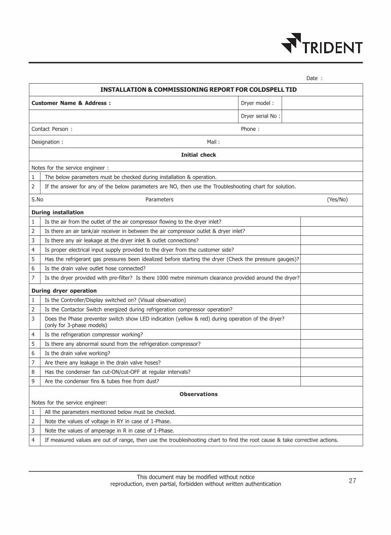
INSTALLATION & COMMISSIONING REPORT FOR COLDSPELL TID
Customer Name & Address : Dryer model :
Dryer serial No :
Contact Person : Phone :
Designation : Mail :
Initial check
Notes for the service engineer :
1 The below parameters must be checked during installation & operation.
2 If the answer for any of the below parameters are NO, then use the Troubleshooting chart for solution.
S.No Parameters (Yes/No)
During installation
1 Is the air from the outlet of the air compressor flowing to the dryer inlet?
2 Is there an air tank/air receiver in between the air compressor outlet & dryer inlet?
3 Is there any air leakage at the dryer inlet & outlet connections?
4 Is proper electrical input supply provided to the dryer from the customer side?
5 Has the refrigerant gas pressures been idealized before starting the dryer (Check the pressure gauges)?
6 Is the drain valve outlet hose connected?
7 Is the dryer provided with pre-filter? Is there 1000 metre minimum clearance provided around the dryer?
During dryer operation
1 Is the Controller/Display switched on? (Visual observation)
2 Is the Contactor Switch energized during refrigeration compressor operation?
3 Does the Phase preventer switch show LED indication (yellow & red) during operation of the dryer?(only for 3-phase models)
4 Is the refrigeration compressor working?
5 Is there any abnormal sound from the refrigeration compressor?
6 Is the drain valve working?
7 Are there any leakage in the drain valve hoses?
8 Has the condenser fan cut-ON/cut-OFF at regular intervals?
9 Are the condenser fins & tubes free from dust?
Observations
Notes for the service engineer:
1 All the parameters mentioned below must be checked.
2 Note the values of voltage in RY in case of 1-Phase.
3 Note the values of amperage in R in case of 1-Phase.
4 If measured values are out of range, then use the troubleshooting chart to find the root cause & take corrective actions.
This document may be modified without noticereproduction, even partial, forbidden without written authentication 25
Date :

.
This document may be modified without noticereproduction, even partial, forbidden without written authentication 27
INSTALLATION & COMMISSIONING REPORT FOR COLDSPELL TID
Customer Name & Address : Dryer model :
Dryer serial No :
Contact Person : Phone :
Designation : Mail :
Initial check
Notes for the service engineer :
1 The below parameters must be checked during installation & operation.
2 If the answer for any of the below parameters are NO, then use the Troubleshooting chart for solution.
S.No Parameters (Yes/No)
During installation
1 Is the air from the outlet of the air compressor flowing to the dryer inlet?
2 Is there an air tank/air receiver in between the air compressor outlet & dryer inlet?
3 Is there any air leakage at the dryer inlet & outlet connections?
4 Is proper electrical input supply provided to the dryer from the customer side?
5 Has the refrigerant gas pressures been idealized before starting the dryer (Check the pressure gauges)?
6 Is the drain valve outlet hose connected?
7 Is the dryer provided with pre-filter? Is there 1000 metre minimum clearance provided around the dryer?
During dryer operation
1 Is the Controller/Display switched on? (Visual observation)
2 Is the Contactor Switch energized during refrigeration compressor operation?
3 Does the Phase preventer switch show LED indication (yellow & red) during operation of the dryer?(only for 3-phase models)
4 Is the refrigeration compressor working?
5 Is there any abnormal sound from the refrigeration compressor?
6 Is the drain valve working?
7 Are there any leakage in the drain valve hoses?
8 Has the condenser fan cut-ON/cut-OFF at regular intervals?
9 Are the condenser fins & tubes free from dust?
Observations
Notes for the service engineer:
1 All the parameters mentioned below must be checked.
2 Note the values of voltage in RY in case of 1-Phase.
3 Note the values of amperage in R in case of 1-Phase.
4 If measured values are out of range, then use the troubleshooting chart to find the root cause & take corrective actions.
Date :

.

S.No Parameters Values Units Range
1 Input supply to the Dryer (from Customer side) --- 1Phase / 3Phase
2 Dryer input Voltage (RY) V Refer specification chart
Dryer input Voltage (YB) V
Dryer input Voltage (RB)
3 Dryer running hours hrs --
4 Refrigerant Used --- R134a / R407C
5 Refrigerant idle pressure (Before switching on the dryer) psi(g) Refer specification chart
6 Dryer inlet air flow (Check air compressor's rated flow) cfm < Dryer capacity
7 Dryer inlet air pressure (measured by pressure gauge) bar (g) 6 – 16
8 Pressure drop between dryer inlet & outlet (measured by pressure gauge) bar (g) < 0.3
9 Dryer inlet air temperature(measured using temperature gun or temperature probe) oC < 45
10 Ambient temperature oC < 40
11 Dewpoint temperature (from dryer display) oC 3 – 7
12 Compressor Suction Pressure (measured by pressure gauge) psi(g) 28-33 (R134a)& 60-70 (R407c)
13 Compressor Discharge Pressure (measured by pressure gauge) psi(g) 140-180 (R134a)& 240-320 (R407c)
14 Compressor Amperage (R) (measured by clamp meter)
Compressor Amperage (Y) (measured by clamp meter) A Refer specification chart
Compressor Amperage (B) (measured by clamp meter)
15 Drain Valve ON/OFF ming (measured by stopwatch) s --
16 Phase preventer OV & UV Setting % OV=5%, UV=10%
Comments :
Customer’s name and signature : Service engineer name and signature :
Name : Name :
Customer Feedback
1. Poor 2. Fair 3. Good 4. V. Good 5. Excellent
1) Have we responded fast to your enquiry? 4) How is the quality of our packing?
2) Are you happy with our order processing method? 5) Does the dryer work as per your expectation?
3) Was the delivery as promised? 6) Suggestions _________________________________________
Rel
ease
dat
e: 3
0th
Sep
2016
This document may be modified without noticereproduction, even partial, forbidden without written authentication 29

.

This document may be modified without noticereproduction, even partial, forbidden without written authentication 31
S.No Parameters Values Units Range
1 Input supply to the Dryer (from Customer side) --- 1Phase / 3Phase
2 Dryer input Voltage (RY) V Refer specification chart
Dryer input Voltage (YB) V
Dryer input Voltage (RB)
3 Dryer running hours hrs --
4 Refrigerant Used --- R134a / R407C
5 Refrigerant idle pressure (Before switching on the dryer) psi(g) Refer specification chart
6 Dryer inlet air flow (Check air compressor's rated flow) cfm < Dryer capacity
7 Dryer inlet air pressure (measured by pressure gauge) bar (g) 6 – 16
8 Pressure drop between dryer inlet & outlet (measured by pressure gauge) bar (g) < 0.3
9 Dryer inlet air temperature(measured using temperature gun or temperature probe) oC < 45
10 Ambient temperature oC < 40
11 Dewpoint temperature (from dryer display) oC 3 – 7
12 Compressor Suction Pressure (measured by pressure gauge) psi(g) 28-33 (R134a)& 60-70 (R407c)
13 Compressor Discharge Pressure (measured by pressure gauge) psi(g) 140-180 (R134a)& 240-320 (R407c)
14 Compressor Amperage (R) (measured by clamp meter)
Compressor Amperage (Y) (measured by clamp meter) A Refer specification chart
Compressor Amperage (B) (measured by clamp meter)
15 Drain Valve ON/OFF ming (measured by stopwatch) s --
16 Phase preventer OV & UV Setting % OV=5%, UV=10%
Comments :
Customer’s name and signature : Service engineer name and signature :
Name : Name :
Customer Feedback
1. Poor 2. Fair 3. Good 4. V. Good 5. Excellent
1) Have we responded fast to your enquiry? 4) How is the quality of our packing?
2) Are you happy with our order processing method? 5) Does the dryer work as per your expectation?
3) Was the delivery as promised? 6) Suggestions _________________________________________
Rel
ease
dat
e: 3
0th
Sep
2016

.

This document may be modified without noticereproduction, even partial, forbidden without written authentication 33
CO
LD
SP
ELL R
EFR
IGER
ATIO
N D
RY
ER
DA
TA
LO
G S
HEET
Da
teT
ime
Dry
er
Dew
Poin
tA
ir
Inle
tA
irSuct
ion
Pre
ssure
(P
sig)*
*D
isch
arg
e Pre
ssure
(Psi
g)*
*D
rain
V
alv
eV
olt
age
(Volt
s)R
unnin
gTe
mpera
ture
Tem
pera
ture
Inle
t/O
utl
et
Work
ing
Peri
od
(3-7
°C)
(Les
sPre
ssure
Sta
tus
than
45°C
)
(DD
:MM
:YY
)(H
ours
:Min
s)(H
ours
)°
C°
CK
g/c
m2
R134a
R4
07
CR
134a
R4
07
C(Y
ES
/NO
)180
to
250
380
to
450
(25-
35)
(55-
65)
(140-1
80)
(240-3
20)
Note
:
Reco
mm
ended O
bse
rvation :
Min
imum
once
in
a day.
If any
of
the obse
rved re
adin
gs
are
either
above
or
belo
w th
e m
entioned va
lues,
conta
ct Serv
ice Exc
ecu
tive
fo
r im
media
te so
lution.
**M
ust
be
check
ed,w
hen
the
dry
er
is
in
opera
tion.

.

Products of Trident Pneumatics Pvt. Ltd. are guaranteed to be
free from defects in materials and workmanship when installed
and operated in accordance with the instructions outlined in the
Instruction Manual.
Trident Pneumatics Pvt. Ltd.'s obligation under this warranty shall
be limited to repair or replacement (at the discretion of Trident)
of defective goods returned to Trident's plant within one (1) year
from the date of commissioning or 18 months from the date of
invoicing which ever is occurring earlier.
Product :
Model : Refer Name Plate
Serial No. :
:
WARRANTY
___________________________Quality Assurance Dept.
Trident Pneumatics Pvt Ltd5/232, K.N.G Pudur Road,
Coimbatore 641 108. Ph : 0422 2400492, 2401373e-mail : [email protected] : www.tridentpneumatics.com

.

Trident sales and service network
Trident Pneumatics Private Limited5/232, KNG Pudur Road, Somayampalayam P.O.Coimbatore 641108, IndiaTelephone : +91-422-2400492 extension 223Fax : +91-422-2401376E-mail : [email protected]
Sales
A. Anil KumarTerritory Manager - Andhra PradeshMobile : +91-9885445321E-mail : [email protected]
Syed YushaTerritory Manager - MumbaiMobile : +91-9867367726E-mail : [email protected]
Ramesh Kumar SinghTerritory Manager - RailwaysMobile : +91-9811310726E-mail : [email protected]
T. SaravanakumarProduct Manager - Drain ValvesMobile : +91-9994978928Telephone : +91-422-2400492 extension 216E-mail : [email protected]
Ramesh Kumar SinghTerritory Manager - DelhiMobile : +91-9811310726E-mail : [email protected]
J. Nandha KumarTerritory Manager - Tamil Nadu/KeralaMobile : +91-9789480564E-mail : [email protected]
Service
M. RagunathService ExecutiveMobile : +91-8870010565Telephone : +91-422-2400492 extension 217E-mail : [email protected]

TRIDENT PNEUMATICS PVT LTD5/232, K.N.G. Pudur Road, Coimbatore - 641 108, India.
Ph : +91-422-2400492 Fax : +91-422-2401376e-mail : [email protected] Website : www.tridentpneumatics.com