Embed Size (px)
Citation preview

MANUAL TRANSMISSION AND DIFFERENTIAL
6-SPEED (6MT)

6MT-2
General DescriptionMANUAL TRANSMISSION AND DIFFERENTIAL
1. General DescriptionA: SPECIFICATION1. MANUAL TRANSMISSION AND FRONT DIFFERENTIAL
2. TRANSMISSION GEAR OIL
Recommended oil:GL-5 (75W-90) or equivalent
Type 6-forward speeds and 1-reverse
Transmission gear ratio
1st 3.636
2nd 2.235
3rd 1.521
4th 1.137
5th 0.971
6th 0.756
Reverse 3.545
Front reduction gear FinalType of gear Hypoid
Gear ratio 3.900
Rear reduction gear
TransferType of gear Helical
Gear ratio 1.103
FinalType of gear Hypoid
Gear ratio 3.545
Front differentialType and number of gear Planetary gear (pinion gear: 8, gear: 2)
LSD type Helical
Center differential Type and number of gearPlanetary gear
(Internal gear: 1, pinion gear: 6, sun gear: 1, and solenoid compression variable control multiplate clutch)
Transmission gear oil GL-5
Transmission gear oil capacity 4.1 2 (4.3 US qt, 3.6 Imp qt)

6MT-3
General DescriptionMANUAL TRANSMISSION AND DIFFERENTIAL
B: COMPONENT1. CLUTCH HOUSING
(1) Gasket (7) Oil seal Tightening torque:N·m (kgf-m, ft-lb)
(2) Plug (8) Clutch release bearing guide T1: 6.4 (0.7, 4.7)
(3) Pitching stopper bracket (9) Return spring bracket T2: 41 (4.2, 30.2)
(4) Clip (10) Plug T3: 50 (5.1, 36.9)
(5) Clutch housing (11) Drain plug T4: 70 (7.1, 51.6)
(6) Gasket T5: 46 (4.7, 33.9)
MT-01701
(5)
(6)
(7)
(8)T3
T4T1
(4)
(3)
(2)(9)
T2
(1)
(10)
(11)
T5

6MT-4
General DescriptionMANUAL TRANSMISSION AND DIFFERENTIAL
2. ADAPTER PLATE
(1) Breather hose (7) Check plug (13) Adapter plate
(2) Transmission harness stay (8) O-ring
(3) Check plug (9) Checking spring Tightening torque:N·m (kgf-m, ft-lb)
(4) O-ring (10) Check ball T1: 18 (1.8, 13.3)
(5) Checking spring (11) Oil guide A T2: 37 (3.8, 27.3)
(6) Plunger (12) Oil guide B T3: 50 (5.1, 36.9)
MT-01609
(2)
(3)
(4)
(1)
(5) (7)
(6)(8)(9)(10)
(13)
T2
T1
T3
T2
T1
T3
(12)
T1
(11)

6MT-5
General DescriptionMANUAL TRANSMISSION AND DIFFERENTIAL
3. TRANSMISSION CASE
(1) Pilot bolt (7) Plunger Tightening torque:N·m (kgf-m, ft-lb)
(2) Neutral position switch (8) Spring T1: 16 (1.6, 11.8)
(3) Back-up light switch (9) Plug T2: 32 (3.3, 23.6)
(4) Adapter plate (10) Gasket T3: 34 (3.5, 25.1)
(5) Transmission case (11) Filler plug T4: 41 (4.2, 30.2)
(6) Harness bracket (12) Band clip T5: 50 (5.1, 36.9)
(2)
(3)
(1)
(10)
(10)
(10)
(4)
(5)
T2T3
T2
T1
(6)
(9)(10)
(8)(7)
T4
T5
(11)
(10)
T5
T5
MT-01702
(12)
(12)
(6) (12)

6MT-6
General DescriptionMANUAL TRANSMISSION AND DIFFERENTIAL
4. OIL PAN AND OIL GUIDE
(1) Transmission case (7) Oil guide F Tightening torque:N·m (kgf-m, ft-lb)
(2) Transfer bearing holder (8) Oil guide D T1: 6.4 (0.7, 4.7)
(3) Oil guide G (9) Oil guide E T2: 18 (1.8, 13.3)
(4) Oil guide H (10) Oil guide C T3: 25 (2.5, 18.4)
(5) Oil pan (11) Filler plug T4: 50 (5.1, 36.9)
(6) Gasket (12) Drain plug
MT-01703
(2)
(3)
(4)
T3
T3
(1)
T2
(10)
(7)
(8)
(9)
(5)
(6)T1T4
T4
(11)
(6)
(12)

6MT-7
General DescriptionMANUAL TRANSMISSION AND DIFFERENTIAL
5. EXTENSION CASE AND CENTER DIFFERENTIAL
(1) Taper roller bearing (14) Snap ring (27) Reverse check lever COMPL
(2) Transfer driven gear (15) Oil guide (28) Straight pin
(3) Taper roller bearing (16) Extension case (29) Reverse check plug
(4) Shim (17) Oil seal (30) Spring
(5) Oil plate (18) Oil seal (31) Gasket
(6) Snap ring (19) Dust cover (32) Plug
(7) Collar (20) Snap ring (33) Plunger
(8) Center differential (21) Washer
(9) Shim (22) Bushing Tightening torque:N·m (kgf-m, ft-lb)
(10) Needle bearing (23) Spring T1: 25 (2.5, 18.4)
(11) Needle bearing (24) Reverse check shaft T2: 41 (4.2, 30.2)
(12) Transfer drive gear (25) Ball bearing T3: 48 (4.9, 35.4)
(13) Ball bearing (with flange) (26) Oil seal
(32)
(31)
(30)
(33)
(27)
(26)(25)
(24)
(23)
(22)(21)
(20)
(19)
(18)(17)
(16)
(15)
(14)
(13)
(12)
(11)
(10)
(5)(4)
(3)
(2)
(9)
(1)
(28)(29)
T3
T1
T2
(8)
MT-01704
(6)(7)

6MT-8
General DescriptionMANUAL TRANSMISSION AND DIFFERENTIAL
6. SHIFTER FORK AND FORK ROD
(1) Spring pin (9) Washer (17) 5th-6th shifter arm
(2) Interlock arm (10) Snap ring (18) 5th-6th fork COMPL
(3) Interlock block (11) Reverse fork COMPL (19) 3rd-4th fork rod
(4) Reverse interlock block (12) Reverse shifter arm (20) 3rd-4th shifter arm
(5) Interlock arm (13) Reverse fork rod (21) 1st-2nd shifter arm
(6) Striking rod (14) Selector arm (22) 3rd-4th fork COMPL
(7) Selector arm No. 2 (15) Shifter arm shaft (23) 1st-2nd fork rod
(8) Neutral set spring (16) 5th-6th fork rod (24) 1st-2nd fork COMPL
(7)
(8)(9) (10)
(15)
(14)
(18)
(17)(22)
(1)
(1)
(20)
(1)
(1)
(1)
(1)
(1)(21)
(24)
(1)
(19)
(16)
(13)
(12)
(11)
(23)
(1)
(1)
(1)(1)
(5)
(6)
(4)
(3)
(2)
MT-01735
6MT-9
General DescriptionMANUAL TRANSMISSION AND DIFFERENTIAL
7. MAIN SHAFT ASSEMBLY
(1) Main shaft (12) 4th bushing (23) Needle bearing
(2) Needle bearing (13) Needle bearing (24) 6th bushing
(3) 3rd drive gear (14) 5th bushing (25) Taper roller bearing
(4) Inner baulk ring (15) Needle bearing (26) Snap ring
(5) Synchro cone (16) 5th drive gear (27) Washer
(6) Outer baulk ring (17) 5th baulk ring (28) Washer
(7) 3rd-4th sleeve (18) 5th-6th sleeve (29) Lock nut
(8) 3rd-4th hub (19) 5th-6th hub
(9) Shifting insert (20) Shifting insert Tightening torque:N·m (kgf-m, ft-lb)
(10) 4th baulk ring (21) 6th baulk ring T: 392 (40.0, 289.1)
(11) 4th gear (22) 6th drive gear
MT-01499
(2)
(16)
(17)
(18)
(19)
(21)
(22)
(23)
(24)
(25)
(26)
(27)
(28)
(29)
(14)
(15)
(3)
(4)
(5)
(6)
(7)
(8)
(9)(1)
(10)
(11)
(12)
(13)
(20)
6MT-10
General DescriptionMANUAL TRANSMISSION AND DIFFERENTIAL
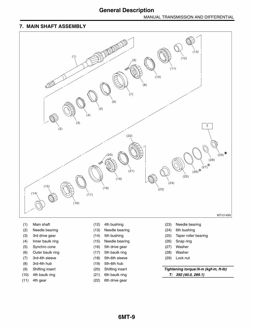
8. DRIVE PINION AND DRIVE SHAFT ASSEMBLY
(1) Drive pinion shaft (13) 1st-2nd sleeve (25) Lock nut
(2) Taper roller bearing (14) Shifting insert (26) Shim
(3) Shim (15) 1st-2nd hub (27) Collar
(4) Washer (16) Outer baulk ring
(5) Lock nut (17) Synchro cone Tightening torque:N·m (kgf-m, ft-lb)
(6) Thrust bearing (18) Inner baulk ring T1: 285 (29.1, 210.2)
(7) Needle bearing (19) 2nd driven gear * 265 (27.0, 195.4)
(8) Driven shaft (20) Needle bearing T2: 570 (58.1, 420.4)
(9) Key (21) 2nd bushing * 530 (54.0, 390.9)
(10) Needle bearing (22) 3rd-4th driven gear T3: 54 (5.5, 39.8)
(11) 1st driven gear (23) 5th-6th driven gear * Tightening torque when using the ST
(12) 1st synchronizer set (24) Ball bearing
MT-01498
(26)(25)
(27)
(16)
(17)
(18)(19)
(20)
(8)
(1)
(2)
(10)
(9)
(11)
(12)
(13)(14)
(15)
(22)
(23)
(24)
(3)
(5)
(6)(7)
T1
T2
(4)
(21)
T3

6MT-11
General DescriptionMANUAL TRANSMISSION AND DIFFERENTIAL
9. REVERSE IDLER GEAR ASSY
(1) Base COMPL (9) Reverse coupling sleeve (17) Reverse idler holder
(2) Counter high and low washer (10) Reverse idler gear (18) Spring pin
(3) Reverse idler gear No. 2 (11) Spring (19) Knock pin
(4) Needle bearing (12) Sub gear (20) Washer
(5) Reverse idler synchro set (13) Friction plate (21) Gasket
(6) Reverse idler gear bushing (14) Snap ring
(7) Needle bearing (15) Counter high and low washer Tightening torque:N·m (kgf-m, ft-lb)
(8) Shifting insert (16) Snap ring T: 25 (2.5, 18.4)
MT-01500
(1)
(9)
(18)
(19)
(8)
(10)
(11)
(12)
(13)
(15)
(16)
(14)
(17)
(2)
(3)(4)
(5)(6)
(7)
T
T
(21)
(21)
(20)

6MT-12
General DescriptionMANUAL TRANSMISSION AND DIFFERENTIAL
10.FRONT DIFFERENTIAL
(1) Drive pinion shaft (5) Oil seal Tightening torque:N·m (kgf-m, ft-lb)
(2) Hypoid driven gear (6) Differential side retainer T1: 25 (2.5, 18.4)
(3) Roller bearing (7) O-ring T2: 69 (7.0, 50.9)
(4) Differential ASSY (8) Retainer lock plate
MT-01705
(1)
(2)
T1
T2
(4)
(3)
(5)
(7)
(6)
(8)
(3)
(7)
(8)T1
(6)
(5)

6MT-13
General DescriptionMANUAL TRANSMISSION AND DIFFERENTIAL
11.TRANSMISSION MOUNTING
(1) Pitching stopper (8) Upper cushion rubber Tightening torque:N·m (kgf-m, ft-lb)
(2) Spacer (9) Center crossmember T1: 7.5 (0.8, 5.5)
(3) Lower cushion rubber (10) Rear plate T2: 35 (3.6, 25.8)
(4) Front plate (11) Front crossmember T3: 50 (5.1, 36.9)
(5) Dynamic damper (12) Rear cushion rubber T4: 58 (5.9, 42.8)
(6) Transmission cushion rubber T5: 70 (7.1, 51.6)
(7) Rear crossmember T6: 140 (14.3, 103.3)
(1)
T4
T5
T5
T5
T2
T6
T2
T3
(2)
(4)
(6)
(12)
(9)
(8)
(3)
(2)
(10)
(7)
(3)
(11)
T1
(5)
MT-01552

6MT-14
General DescriptionMANUAL TRANSMISSION AND DIFFERENTIAL
C: CAUTION• Wear appropriate work clothing, including a cap,protective goggles and protective shoes when per-forming any work.• Remove contamination including dirt and corro-sion before removal, installation or disassembly.• Keep the disassembled parts in order and pro-tect them from dust and dirt.• Before removal, installation or disassembly, besure to clarify the abnormal condition. Avoid unnec-essary removal, installation, disassembly and re-placement.• When disassembling the case and other light al-loy parts, disassemble by using a plastic hammer.Do not pry apart with screwdrivers or other tools.• Vehicle components are extremely hot after driv-ing. Be wary of receiving burns from heated parts.• Use SUBARU genuine transmission gear oil,grease or the equivalent. Do not mix transmissiongear oil, grease etc. of different grades or manufac-turers.• Be sure to tighten fasteners including bolts andnuts to the specified torque.• Place shop jacks or rigid racks at the specifiedpoints.• Apply transmission gear oil onto sliding or revolv-ing surfaces before installation.• Always replace deformed or damaged snaprings.• Before installing O-rings or oil seals, apply suffi-cient amount of transmission gear oil to avoid dam-age and deformation.• Be careful not to incorrectly install or fail to installO-rings, snap rings and other parts.• Before securing a part on a vise, place cushion-ing materials such as wood blocks, aluminumplates, or waste cloth between the part and thevise.• Avoid damaging the mating surface of the case.• Before applying liquid gasket, completely re-move the old liquid gasket.
6MT-15
General DescriptionMANUAL TRANSMISSION AND DIFFERENTIAL
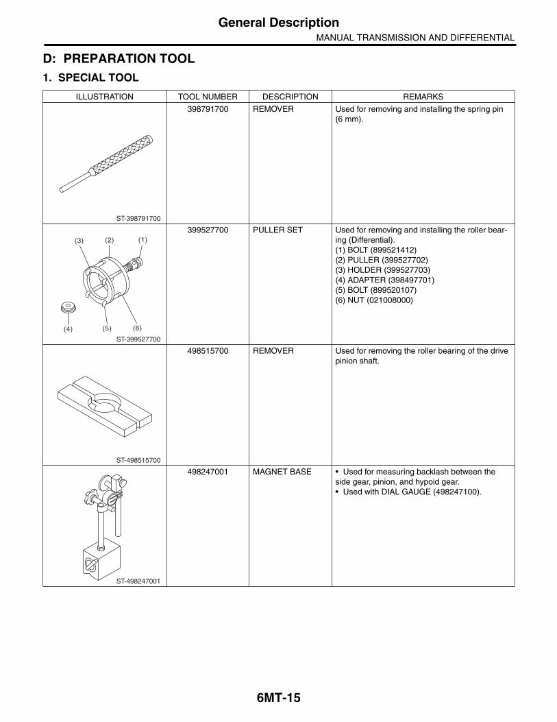
D: PREPARATION TOOL1. SPECIAL TOOL
ILLUSTRATION TOOL NUMBER DESCRIPTION REMARKS
398791700 REMOVER Used for removing and installing the spring pin (6 mm).
399527700 PULLER SET Used for removing and installing the roller bear-ing (Differential).(1) BOLT (899521412)(2) PULLER (399527702)(3) HOLDER (399527703)(4) ADAPTER (398497701)(5) BOLT (899520107)(6) NUT (021008000)
498515700 REMOVER Used for removing the roller bearing of the drive pinion shaft.
498247001 MAGNET BASE • Used for measuring backlash between the side gear, pinion, and hypoid gear.• Used with DIAL GAUGE (498247100).
ST-398791700
ST-399527700
(1)(2)(3)
(4) (5) (6)
ST-498515700
ST-498247001

6MT-16
General DescriptionMANUAL TRANSMISSION AND DIFFERENTIAL
498247100 DIAL GAUGE • Used for measuring backlash between the side gear, pinion, and hypoid gear.• Used with MAGNET BASE (498247001).
498077000 REMOVER Used for removing the differential taper roller bearing.
899858600 REMOVER Used for removing the roller bearing.
499757002 INSTALLER Used for installing the bearing cone of the trans-fer driven gear (extension core side).
18630AA010 WRENCH COMPL RETAINER
• Used for removing and installing the differen-tial side retainer RH.• WRENCH ASSEMBLY (499787000) can also be used.
ILLUSTRATION TOOL NUMBER DESCRIPTION REMARKS
ST-498247100
ST-498077000
ST-899858600
ST-499757002
ST18630AA010

6MT-17
General DescriptionMANUAL TRANSMISSION AND DIFFERENTIAL
499877000 RACE 4-5 INSTALLER
Used for disassembling the driven shaft and transfer driven gear.
899864100 REMOVER Used for removing the transmission main shaft and drive pinion parts.
498057300 INSTALLER Used for installing the extension oil seal.
498255400 PLATE Used for measuring backlash.
41099AA010 ENGINE SUPPORT BRACKET
Used for supporting engine.
ILLUSTRATION TOOL NUMBER DESCRIPTION REMARKS
ST-499877000
ST-899864100
ST-498057300
ST-498255400
ST41099AA010

6MT-18
General DescriptionMANUAL TRANSMISSION AND DIFFERENTIAL
41099AA020 ENGINE SUPPORT Used for supporting engine.
398527700 PULLER ASSY Used for removing the extension case oil seal and the front side retainer bearing outer race.
398643600 GAUGE Used for measuring the total end play, extension end play and drive pinion height.
398177700 INSTALLER Used for assembling the main shaft.
399893600 PLIER • Used for removing and installing the neutral set spring.• Used together with the CLAW (18756AA000).
ILLUSTRATION TOOL NUMBER DESCRIPTION REMARKS
ST41099AA020
ST-398527700
ST-398643600
ST-398177700
ST-399893600
6MT-19
General DescriptionMANUAL TRANSMISSION AND DIFFERENTIAL
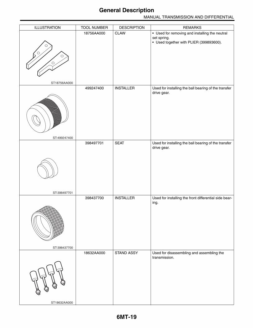
18756AA000 CLAW • Used for removing and installing the neutral set spring.• Used together with PLIER (399893600).
499247400 INSTALLER Used for installing the ball bearing of the transfer drive gear.
398497701 SEAT Used for installing the ball bearing of the transfer drive gear.
398437700 INSTALLER Used for installing the front differential side bear-ing.
18632AA000 STAND ASSY Used for disassembling and assembling the transmission.
ILLUSTRATION TOOL NUMBER DESCRIPTION REMARKS
ST18756AA000
ST-499247400
ST-398497701
ST-398437700
ST18632AA000

6MT-20
General DescriptionMANUAL TRANSMISSION AND DIFFERENTIAL
18671AA000 OIL SEAL GUIDE • Used for installing the oil seal to the reverse check.• Used together with the INSTALLER (18657AA010).
18657AA010 INSTALLER • Used for installing the oil seal to the reverse check.• Used together with the OIL SEAL GUIDE (18671AA000).
18657AA000 INSTALLER Used for installing the oil seal to the shift rod.
18758AA000 PULLER Used for removing the extension taper roller bearing outer race.
18831AA000 GAUGE Used for measuring the extension taper roller bearing.
ILLUSTRATION TOOL NUMBER DESCRIPTION REMARKS
ST18671AA000
ST18657AA010
ST18657AA000
ST18758AA000
ST18831AA000

6MT-21
General DescriptionMANUAL TRANSMISSION AND DIFFERENTIAL
18631AA000 HANDLE Used for measuring the front differential back-lash.
18754AA000 REMOVER Used to remove parts of the driven gear.
18757AA000 STRAIGHT PIN REMOVER
Used for installing the reverse idler gear.
18665AA000 HOLDER • Used for removing and installing the main shaft lock nut.• Used together with the BASE (18664AA000).
18666AA000 HOLDER • Used for removing and installing the driven shaft lock nut.• Used together with the BASE (18664AA000).
ILLUSTRATION TOOL NUMBER DESCRIPTION REMARKS
ST18631AA000
ST18754AA000
ST18757AA000
ST18665AA000
ST18666AA000

6MT-22
General DescriptionMANUAL TRANSMISSION AND DIFFERENTIAL
18667AA000 HOLDER • Used for removing and installing the drive pin-ion shaft lock nut.• Used together with the BASE (18664AA000).
18664AA000 BASE • Used for removing and installing the main shaft lock nut.• Used for removing and installing the drive pin-ion shaft lock nut.• Used for removing and installing the driven shaft lock nut.
18722AA010 REMOVER Used for disassembling the main shaft.
18651AA000 INSTALLER Used for assembling the main shaft.
18852AA000 TORQUE WRENCH • Used to tighten the main shaft lock nut.• Used to tighten the drive pinion shaft lock nut.• Used to tighten the driven shaft lock nut.
ILLUSTRATION TOOL NUMBER DESCRIPTION REMARKS
ST18667AA000
ST18664AA000
ST18722AA010
ST18651AA000
ST18852AA000
6MT-23
General DescriptionMANUAL TRANSMISSION AND DIFFERENTIAL
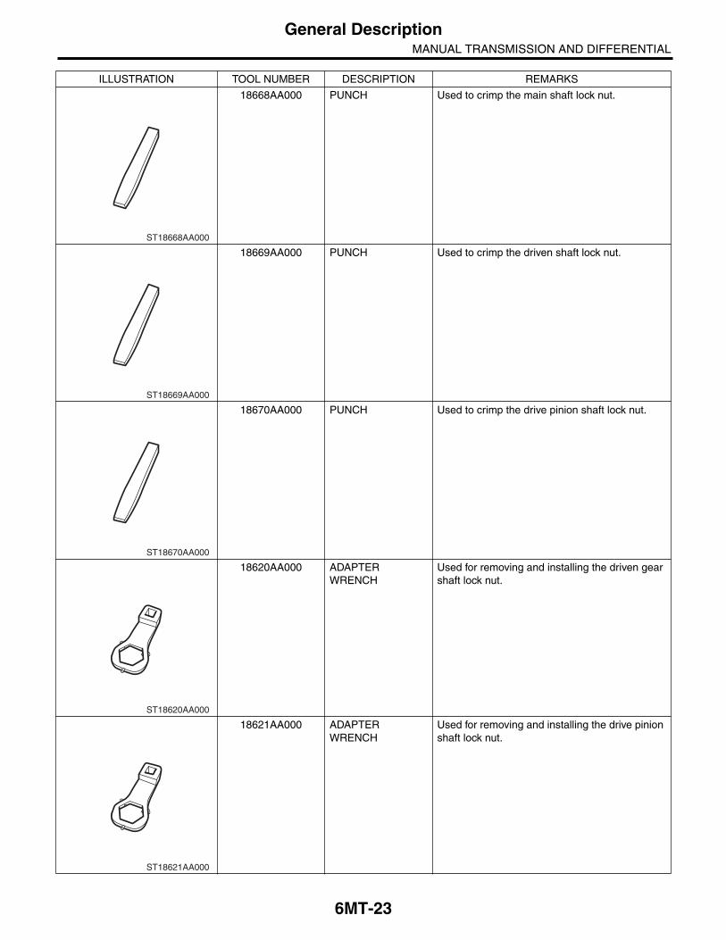
18668AA000 PUNCH Used to crimp the main shaft lock nut.
18669AA000 PUNCH Used to crimp the driven shaft lock nut.
18670AA000 PUNCH Used to crimp the drive pinion shaft lock nut.
18620AA000 ADAPTER WRENCH
Used for removing and installing the driven gear shaft lock nut.
18621AA000 ADAPTER WRENCH
Used for removing and installing the drive pinion shaft lock nut.
ILLUSTRATION TOOL NUMBER DESCRIPTION REMARKS
ST18668AA000
ST18669AA000
ST18670AA000
ST18620AA000
ST18621AA000

6MT-24
General DescriptionMANUAL TRANSMISSION AND DIFFERENTIAL
18723AA000 REMOVER Used for disassembling the driven shaft.
18630AA000 WRENCH ASSY Used for removing and installing the differential side retainer LH.
18672AA000 GUIDE CLIP Used for installing the reverse idler snap ring.
18720AA000 REMOVER Used for disassembling the main shaft.
18654AA000 INSTALLER Used for assembling the driven shaft.
ILLUSTRATION TOOL NUMBER DESCRIPTION REMARKS
ST18723AA000
ST18630AA000
ST18672AA000
ST18720AA000
ST18654AA000

6MT-25
General DescriptionMANUAL TRANSMISSION AND DIFFERENTIAL
18663AA000 SOCKET Used for removing and installing the transfer bearing holder.
18853AA000 HEIGHT GAUGE Used for selecting the shift rod.
18760AA000 CLAW • Used for removing the front side retainer bear-ing outer race.• Used together with PULLER ASSY (398527700).
18675AA000 DIFFERENTIAL SIDE OIL SEAL INSTALLER
Used for installing the differential side retainer oil seal.
28399SA010 OIL SEAL PROTEC-TOR
Used for protecting oil seal when installing front drive shaft.
ILLUSTRATION TOOL NUMBER DESCRIPTION REMARKS
ST18663AA000
ST18853AA000
ST18760AA000
ST18675AA000
ST28399SA010

6MT-26
General DescriptionMANUAL TRANSMISSION AND DIFFERENTIAL
2. GENERAL TOOL
18657AA020 OIL SEAL INSTALLER
Used for installing the oil seal.
18270KA020 SOCKET (E20) Used for removing and installing the hypoid driven gear.
TOOL NAME REMARKS
Circuit tester Used for measuring resistance, voltage and current.
TORX® bit T70 Used for removing and installing transmission gear oil drain plug.
Depth gauge Used for measuring the transmission end play.
ILLUSTRATION TOOL NUMBER DESCRIPTION REMARKS
ST18657AA020
ST18270KA020

6MT-27
Transmission Gear OilMANUAL TRANSMISSION AND DIFFERENTIAL
2. Transmission Gear OilA: INSPECTION1) Lift up the vehicle.2) Remove the transmission under cover.3) Remove the filler plug, and then check the trans-mission gear oil.
4) Check that the transmission gear oil level is up tothe bottom of the filler plug. If the transmission gearoil level is low, refill up to the bottom of filler plug. 5) Using a new gasket, and tighten the filler plug.
Tightening torque:50 N·m (5.1 kgf-m, 36.9 ft-lb)
B: REPLACEMENT1) Lift up the vehicle.2) Remove the transmission under cover.3) Remove the filler plug.
4) Remove the two drain plugs (oil pan side, clutchhousing side), and then drain the transmission gearoil completely.
CAUTION:• Immediately after the engine has been run-ning, the transmission gear oil is hot. Be carefulnot to burn yourself.• Be careful not to spill the transmission gearoil on exhaust pipe to prevent it from emittingsmoke or causing fires. If transmission gear oilis spilled on the exhaust pipe, wipe it off com-pletely.
NOTE:• Tighten the drain plug of the transmission gearoil after draining the transmission gear oil.• Always use a new gasket.• Use TORX® bit T70 to remove and install thedrain plug on clutch housing side.
Tightening torque:Oil pan side
50 N·m (5.1 kgf-m, 36.9 ft-lb)Clutch housing side
70 N·m (7.1 kgf-m, 51.6 ft-lb)
5) Pour transmission gear oil to the bottom end offiller plug.
NOTE:Carefully refill transmission gear oil while checkingthe level. Excessive or insufficient oil must beavoided.
RECOMMENDED GEAR OILUse GL-5 or the equivalent.
Transmission gear oil capacity4.1 2 (4.3 US qt, 3.6 Imp qt)
6) Check the level of the transmission gear oil.7) Using a new gasket, and tighten the filler plug.
Tightening torque:50 N·m (5.1 kgf-m, 36.9 ft-lb)
(A) Filler plug
(A) Filler plug
MT-01706
(A)
MT-01706
(A)
(A) Drain plug (oil pan side)
(B) Drain plug (clutch housing side)
MT-01549
(A)
(B)

6MT-28
Oil SealMANUAL TRANSMISSION AND DIFFERENTIAL
3. Oil SealA: INSPECTIONCheck that there is no oil leaking from the oil seal.If there is any deformation, hardening, wear or oth-er malfunctions of the oil seal, perform the follow-ing:• Replace the oil seal.• Inspect the propeller shaft.
B: REPLACEMENT1) Clean the transmission exterior.2) Drain transmission gear oil completely. <Ref. to6MT-27, REPLACEMENT, Transmission GearOil.>3) Remove the rear exhaust pipe and muffler.4) Remove the heat shield cover.5) Remove the propeller shaft. <Ref. to DS-10, RE-MOVAL, Propeller Shaft.>6) Using the ST, remove the oil seal.ST 398527700 PULLER ASSY
7) Using the ST, install the oil seal.ST 498057300 INSTALLER
8) Install the propeller shaft. <Ref. to DS-11, IN-STALLATION, Propeller Shaft.>9) Install the heat shield cover.10) Install the rear exhaust pipe and muffler.11) Pour in transmission gear oil and check the oillevel. <Ref. to 6MT-27, REPLACEMENT, Trans-mission Gear Oil.>
(A) Oil seal
MT-00451
(A)ST
MT-00099
6MT-29
Differential Side Retainer Oil SealMANUAL TRANSMISSION AND DIFFERENTIAL
4. Differential Side Retainer Oil Seal
A: INSPECTIONCheck that there is no oil leaking from the differen-tial side retainer oil seal. If there is oil leakage, per-form the following procedures.• Replace the oil seal.• Check the front drive shaft.
B: REPLACEMENT1) Lift up the vehicle.2) Remove the front exhaust pipe and center ex-haust pipe. <Ref. to EX(STI)-5, REMOVAL, FrontExhaust Pipe.>3) Drain transmission gear oil completely. <Ref. to6MT-27, REPLACEMENT, Transmission GearOil.>4) Separate the front drive shaft from the transmis-sion. <Ref. to DS-25, REMOVAL, Front DriveShaft.>5) Remove the differential side retainer oil seal byusing a flat tip screwdriver or similar tools.6) Using the ST, install the differential side retaineroil seal by lightly tapping with a hammer.ST 18675AA000 DIFFERENTIAL SIDE OIL
SEAL INSTALLER7) Apply transmission gear oil to the oil seal lips.8) Set the ST to the side retainer.ST 28399SA010 OIL SEAL PROTECTOR9) Install the front drive shaft into the transmission.
NOTE:Replace the circlip of drive shaft with a new part.10) Install the front drive shaft into transmission, re-move the ST and insert the drive shaft securely.ST 28399SA010 OIL SEAL PROTECTOR11) Install the front exhaust pipe and the center ex-haust pipe. <Ref. to EX(STI)-6, INSTALLATION,Front Exhaust Pipe.>12) Pour transmission gear oil to the bottom end offiller plug. <Ref. to 6MT-27, REPLACEMENT,Transmission Gear Oil.>13) Lower the vehicle.

6MT-30
Transmission Mounting SystemMANUAL TRANSMISSION AND DIFFERENTIAL
5. Transmission Mounting System
A: REMOVAL1. PITCHING STOPPER1) Disconnect the ground cable from the battery.2) Remove the intercooler. <Ref. to IN(STI)-11,REMOVAL, Intercooler.>3) Remove the pitching stopper.
2. CROSSMEMBER AND CUSHION RUBBER1) Disconnect the ground cable from the battery.2) Lift up the vehicle.3) Remove the transmission under cover.4) Remove the center exhaust pipe. <Ref. toEX(STI)-7, REMOVAL, Center Exhaust Pipe.>5) Remove the rear exhaust pipe and muffler.<Ref. to EX(STI)-12, REMOVAL, Rear ExhaustPipe.> <Ref. to EX(STI)-14, REMOVAL, Muffler.>6) Remove the heat shield cover.7) Set the transmission jack under the transmissionbody.
CAUTION:Always support the transmission case with atransmission jack.8) Remove the rear crossmember.
9) Remove the rear cushion rubber.
B: INSTALLATION1. PITCHING STOPPER1) Install the pitching stopper.
Tightening torque:T1: 50 N·m (5.1 kgf-m, 36.9 ft-lb)T2: 58 N·m (5.9 kgf-m, 42.8 ft-lb)
2) Install the intercooler. <Ref. to IN(STI)-12, IN-STALLATION, Intercooler.>3) Connect the battery ground cable to the battery.
2. CROSSMEMBER AND CUSHION RUBBER1) Install the rear cushion rubber.
Tightening torque:35 N·m (3.6 kgf-m, 25.8 ft-lb)
2) Install the crossmember.
Tightening torque:T1: 70 N·m (7.1 kgf-m, 51.6 ft-lb)T2: 140 N·m (14.3 kgf-m, 103 ft-lb)
3) Remove the transmission jack.4) Install the heat shield cover.5) Install the rear exhaust pipe and muffler. <Ref. toEX(STI)-12, INSTALLATION, Rear Exhaust Pipe.><Ref. to EX(STI)-14, INSTALLATION, Muffler.>6) Install the center exhaust pipe. <Ref. to EX(STI)-8, INSTALLATION, Center Exhaust Pipe.>
MT-01300
MT-01264
MT-01301T1T2
MT-01265
T1
T2T2
T1

6MT-31
Transmission Mounting SystemMANUAL TRANSMISSION AND DIFFERENTIAL
C: INSPECTIONPerform the following inspection procedures andrepair or replace faulty parts.
1. PITCHING STOPPERCheck the pitching stopper for bends or damage.Check that the rubber is not stiff, cracked or other-wise damaged.
2. CROSSMEMBER AND CUSHION RUBBERCheck crossmember for bends or damage. Checkthat the cushion rubber is not stiff, cracked, or oth-erwise damaged.

6MT-32
Manual Transmission AssemblyMANUAL TRANSMISSION AND DIFFERENTIAL
6. Manual Transmission Assembly
A: REMOVAL1) Set the vehicle on a lift.2) Open the front hood completely.3) Disconnect the ground cable from the battery.4) Remove the intercooler. <Ref. to IN(STI)-11,REMOVAL, Intercooler.>5) Disconnect the following harness connectors,and then remove the engine hanger rear.
6) Remove the secondary air combination valve.<Ref. to EC(STI)-23, SECONDARY AIR COMBI-NATION VALVE LH, REMOVAL, Secondary AirCombination Valve.>
7) Disconnect the ground cable on the upper sideof the transmission case and body.
8) Remove the starter assembly. <Ref. to SC(STI)-5, REMOVAL, Starter.>9) Remove the operating cylinder from the trans-mission.
NOTE:Hang the removed operating cylinder with a pieceof wire.
10) Remove the pitching stopper and pitching stop-per bracket.
(A) Front oxygen (A/F) sensor connector
(B) Rear oxygen sensor connector
(C) Neutral position switch backup light switch con-nector
MT-01740
(A)
(B)
(C)
MT-01266
MT-01267
CL-00445

6MT-33
Manual Transmission AssemblyMANUAL TRANSMISSION AND DIFFERENTIAL
11) Set the ST.ST1 41099AA010 ENGINE SUPPORT
BRACKETST2 41099AA020 ENGINE SUPPORT
12) Remove the clutch release shaft.(1) Remove the plug using a hexagon wrench.(2) Attach a 6 mm (0.24 in) bolt to the releaseshaft, and pull out the release shaft.(3) Lift the release fork, and remove from theclaw of the release bearing. Pull the releasefork to the engine side, and make it so that itmoves freely.
13) Remove the front wheels.14) Lift up the vehicle, and remove the transmis-sion under cover.15) Drain transmission gear oil completely. <Ref. to6MT-27, REPLACEMENT, Transmission GearOil.>16) Remove the center exhaust pipe. <Ref. toEX(STI)-7, REMOVAL, Center Exhaust Pipe.>17) Remove the rear exhaust pipe and muffler.<Ref. to EX(STI)-12, REMOVAL, Rear ExhaustPipe.> <Ref. to EX(STI)-14, REMOVAL, Muffler.>
CAUTION:When removing the exhaust pipes, be carefuleach exhaust pipe does not drop out.18) Remove the bolts which hold upper side oftransmission to engine.
19) Remove the heat shield cover.20) Remove the propeller shaft. <Ref. to DS-10,REMOVAL, Propeller Shaft.>
21) Remove the front stabilizer link.
22) Remove the ball joint of front arm from thehousing.
23) Remove the front drive shaft. <Ref. to DS-25,REMOVAL, Front Drive Shaft.>24) Set the transmission jack under the transmis-sion, and remove the front crossmember and rearcrossmember.
MT-01526
ST2
ST1
MT-01524
FS-00117
FS-00106
MT-01264

6MT-34
Manual Transmission AssemblyMANUAL TRANSMISSION AND DIFFERENTIAL
25) Move the transmission to the right side of thevehicle, and remove the joint COMPL, stay boltsand reverse check cable.
NOTE:If the transmission is not moved aside, the jointCOMPL and stay bolts may contact the body andcause damage.
26) Tighten the turnbuckle of the ST to tilt the en-gine assembly towards the back.
27) Remove the bolts and nuts holding the bottomof transmission to the engine, and remove thetransmission from the vehicle.
NOTE:• During removal, be careful not to hit the trans-mission against the body when pulling towards therear.• The clutch pipe and breather pipe may interferewith each other. Remove carefully.
B: INSTALLATION1) Set the release fork, release bearing and releaseshaft to the transmission. <Ref. to CL-11, INSTAL-LATION, Release Bearing and Lever.>2) Replace the front differential side retainer oilseal.
(1) Remove the oil seal by using flat tip screw-driver etc.(2) Apply gear oil to the lip of new oil seals.(3) Install a new oil seal using ST.
ST 18675AA000 DIFFERENTIAL SIDE OIL SEAL INSTALLER
NOTE:Be sure to replace the differential side oil seal afterthe procedure of removing front drive shaft fromtransmission.3) Loosen the turnbuckle of ST to return the engineto its original position.
4) Install the transmission.5) Tighten the bolts and nuts which hold the lowerside of transmission to the engine.
NOTE:• Make sure that the main shaft spline is complete-ly inserted.• Make sure that the rear end of the engine is setlow.
Tightening torque:50 N·m (5.1 kgf-m, 36.9 ft-lb)
(A) Joint COMPL bolt
(B) Stay bolt
(C) Reverse check cable
MT-00886
(C)
(A)
(B)
MT-00463
MT-01090
MT-01527
MT-00464
6MT-35
Manual Transmission AssemblyMANUAL TRANSMISSION AND DIFFERENTIAL
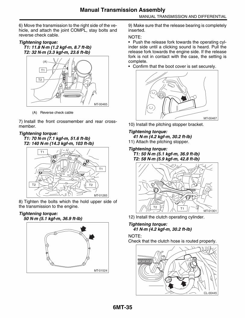
6) Move the transmission to the right side of the ve-hicle, and attach the joint COMPL, stay bolts andreverse check cable.
Tightening torque:T1: 11.8 N·m (1.2 kgf-m, 8.7 ft-lb)T2: 32 N·m (3.3 kgf-m, 23.6 ft-lb)
7) Install the front crossmember and rear cross-member.
Tightening torque:T1: 70 N·m (7.1 kgf-m, 51.6 ft-lb)T2: 140 N·m (14.3 kgf-m, 103 ft-lb)
8) Tighten the bolts which the hold upper side ofthe transmission to the engine.
Tightening torque:50 N·m (5.1 kgf-m, 36.9 ft-lb)
9) Make sure that the release bearing is completelyinserted.
NOTE:• Push the release fork towards the operating cyl-inder side until a clicking sound is heard. Pull therelease fork towards the engine side. If the releasefork is not in contact with the case, the setting iscomplete.• Confirm that the boot cover is set securely.
10) Install the pitching stopper bracket.
Tightening torque:41 N·m (4.2 kgf-m, 30.2 ft-lb)
11) Attach the pitching stopper.
Tightening torque:T1: 50 N·m (5.1 kgf-m, 36.9 ft-lb)T2: 58 N·m (5.9 kgf-m, 42.8 ft-lb)
12) Install the clutch operating cylinder.
Tightening torque:41 N·m (4.2 kgf-m, 30.2 ft-lb)
NOTE:Check that the clutch hose is routed properly.
(A) Reverse check cable
MT-00465
(A)
T2
T1
MT-01265
T1
T2T2
T1
MT-01524
MT-00467
MT-01301T1T2
CL-00445

6MT-36
Manual Transmission AssemblyMANUAL TRANSMISSION AND DIFFERENTIAL
13) Install the starter assembly. <Ref. to SC(STI)-5, INSTALLATION, Starter.>14) Attach the ground cable to the transmissionand body.
15) Install the secondary air combination valve.<Ref. to EC(STI)-24, SECONDARY AIR COMBI-NATION VALVE LH, INSTALLATION, SecondaryAir Combination Valve.>
16) Connect the following harness connectors,then attach the engine hanger rear.
17) Set the ST to side retainer.ST 28399SA010 OIL SEAL PROTECTOR18) Install the front drive shaft into the transmis-sion.
NOTE:Replace the circlip of drive shaft with a new part.19) Install the front drive shaft into transmission, re-move the ST and insert the drive shaft securely.ST 28399SA010 OIL SEAL PROTECTOR20) Install the ball joint of the front arm.
Tightening torque:50 N·m (5.1 kgf-m, 36.9 ft-lb)
MT-01266
MT-01267 (A) Front oxygen (A/F) sensor connector
(B) Rear oxygen sensor connector
(C) Neutral position switch backup light switch connector
MT-01740
(A)
(B)
(C)
FS-00106

6MT-37
Manual Transmission AssemblyMANUAL TRANSMISSION AND DIFFERENTIAL
21) Install the front stabilizer link.
Tightening torque:45 N·m (4.6 kgf-m, 33.2 ft-lb)
NOTE:Use a new self-locking nut.
22) Install the propeller shaft. <Ref. to DS-11, IN-STALLATION, Propeller Shaft.>23) Install the heat shield cover.24) Install the rear exhaust pipe and muffler. <Ref. toEX(STI)-12, INSTALLATION, Rear Exhaust Pipe.><Ref. to EX(STI)-14, INSTALLATION, Muffler.>25) Install the center exhaust pipe. <Ref. toEX(STI)-8, INSTALLATION, Center Exhaust Pipe.>26) Fill the transmission gear oil. <Ref. to 6MT-27,REPLACEMENT, Transmission Gear Oil.>27) Install the transmission under cover.28) Install the intercooler. <Ref. to IN(STI)-12, IN-STALLATION, Intercooler.>29) Connect the battery ground cable to the bat-tery.
FS-00117

6MT-38
Preparation for OverhaulMANUAL TRANSMISSION AND DIFFERENTIAL
7. Preparation for OverhaulA: PROCEDURE1) Clean oil, grease, dirt and dust from the trans-mission.2) Attach the transmission to ST.ST 18632AA000 STAND ASSY
3) Apply oil to rotating parts before assembly.4) When reusing disassembled parts, reinstall inthe original positions and directions.5) Gaskets, lock washers and lock nuts must be re-placed with new parts.6) Apply liquid gasket to the specified areas to pre-vent leakage.
MT-00468ST
ST
ST

6MT-39
Air Breather HoseMANUAL TRANSMISSION AND DIFFERENTIAL
8. Air Breather HoseA: REMOVALDisconnect the air breather hose.
B: INSTALLATIONConnect the air breather hose.
C: INSPECTIONMake sure the hose is not cracked or clogged.
MT-01707
MT-01707

6MT-40
Back-up Light SwitchMANUAL TRANSMISSION AND DIFFERENTIAL
9. Back-up Light SwitchA: REMOVAL1) Remove the manual transmission assemblyfrom the vehicle. <Ref. to 6MT-32, REMOVAL,Manual Transmission Assembly.>2) Disconnect the back-up light switch connector.
3) Disconnect the back-up light switch.
B: INSTALLATION1) Install the back-up light switch.
NOTE:Use a new gasket.
Tightening torque:32 N·m (3.3 kgf-m, 23.6 ft-lb)
2) Connect the back-up light switch connector.
3) Install the manual transmission assembly to thevehicle. <Ref. to 6MT-34, INSTALLATION, ManualTransmission Assembly.>
(A) Back-up light switch connector (Gray)
(B) Neutral position switch connector (Brown)
(C) Clip
(A) Back-up light switch
(B) Neutral position switch
MT-00471
(A)
(B)
(C)(C)
MT-00472
(A)(B)
(A) Back-up light switch
(B) Neutral position switch
(A) Back-up light switch connector (Gray)
(B) Neutral position switch connector (Brown)
(C) Clip
MT-00472
(A)(B)
MT-00471
(A)
(B)
(C)(C)

6MT-41
Back-up Light SwitchMANUAL TRANSMISSION AND DIFFERENTIAL
C: INSPECTION1) Disconnect the ground cable from the battery.2) Remove the intercooler. <Ref. to IN(STI)-11,REMOVAL, Intercooler.>3) Disconnect the transmission harness and chas-sis harness.
4) Measure the resistance between the back-uplight switch terminals. If it is not within the specifica-tion, replace the back-up light switch.
(A) Transmission connector
(B) Pitching stopper
Gear shift position Terminal No. Specification
Back position3 and 6
Less than 1
Other positions 1 M or more
MT-01741
(A)
(B)
256
14
3
MT-00946

6MT-42
Neutral Position SwitchMANUAL TRANSMISSION AND DIFFERENTIAL
10.Neutral Position SwitchA: REMOVAL1) Remove the manual transmission assemblyfrom the vehicle. <Ref. to 6MT-32, REMOVAL,Manual Transmission Assembly.>2) Disconnect the connector and clip of the neutralposition switch.
3) Remove the neutral position switch.
B: INSTALLATION1) Install the neutral position switch.
NOTE:Use a new gasket.
Tightening torque:32 N·m (3.3 kgf-m, 23.6 ft-lb)
2) Connect the connector and clip of the neutral po-sition switch.
3) Install the manual transmission assembly to thevehicle. <Ref. to 6MT-34, INSTALLATION, ManualTransmission Assembly.>
(A) Back-up light switch connector (Gray)
(B) Neutral position switch connector (Brown)
(C) Clip
(A) Back-up light switch
(B) Neutral position switch
MT-00471
(A)
(B)
(C)(C)
MT-00472
(A)(B)
(A) Back-up light switch
(B) Neutral position switch
(A) Back-up light switch connector (Gray)
(B) Neutral position switch connector (Brown)
(C) Clip
MT-00472
(A)(B)
MT-00471
(A)
(B)
(C)(C)

6MT-43
Neutral Position SwitchMANUAL TRANSMISSION AND DIFFERENTIAL
C: INSPECTION1) Disconnect the ground cable from the battery.2) Remove the intercooler. <Ref. to IN(STI)-11,REMOVAL, Intercooler.>3) Disconnect the transmission harness and chas-sis harness.
4) Measure the resistance between neutral posi-tion switch terminals. If not within the standard val-ues, replace the neutral position switch.
(A) Transmission connector
(B) Pitching stopper
Gear shift position Terminal No. Specification
Neutral position2 and 5
Less than 1
Other positions 1 M or more
MT-01741
(A)
(B)
14
3562
MT-00947

6MT-44
Extension CaseMANUAL TRANSMISSION AND DIFFERENTIAL
11.Extension CaseA: REMOVAL1) Remove the manual transmission assemblyfrom the vehicle. <Ref. to 6MT-32, REMOVAL,Manual Transmission Assembly.>2) Prepare the transmission for overhaul. <Ref. to6MT-38, Preparation for Overhaul.>3) Remove the extension case.
4) Remove any remaining liquid gasket from theextension case and transmission case.
B: INSTALLATION1) Select the thrust washer of the transfer drivengear, and attach to the extension case. <Ref. to6MT-47, ADJUSTMENT, Extension Case.>2) Apply a thin coat of oil to the outer surface of thebearing cone, and attach to the extension case.3) Select the thrust washer of the transfer drivegear, and attach to the center differential.4) Apply liquid gasket to the transmission case.
Liquid gasket:THREE BOND 1215 (Part No. 004403007) or equivalent
5) Install the extension case.
Tightening torque:48 N·m (4.9 kgf-m, 35.4 ft-lb)
NOTE:Insert the stopper section of the center differentialbetween the oil guide.
6) Install the manual transmission assembly to thevehicle. <Ref. to 6MT-34, INSTALLATION, ManualTransmission Assembly.>
MT-00475
MT-00476
(A) Oil guide
(B) Stopper
(C) Center differential
(D) Extension Case
MT-00475
MT-00973
(A)
(B)
(C)
(D)

6MT-45
Extension CaseMANUAL TRANSMISSION AND DIFFERENTIAL
C: DISASSEMBLY1) Remove the transfer drive gear. <Ref. to 6MT-54, REMOVAL, Transfer Drive Gear.>2) Remove the oil guide.
3) Remove the shift bracket.
4) Remove the bearing cone using the ST.ST 18758AA000 PULLER
5) Remove the thrust washer and oil plate.
6) Remove the shifter arm oil seal.
7) Remove the reverse check system. <Ref. to6MT-51, REMOVAL, Reverse Check System.>8) Remove the extension oil seal. <Ref. to 6MT-28,REPLACEMENT, Oil Seal.>
(A) Bearing cone
(A) Thrust washer
(B) Oil plate
MT-00477
MT-00478
MT-00479
(A)
ST
MT-00480
(A)
(B)
(A) Oil seal
MT-00481(A)
6MT-46
Extension CaseMANUAL TRANSMISSION AND DIFFERENTIAL
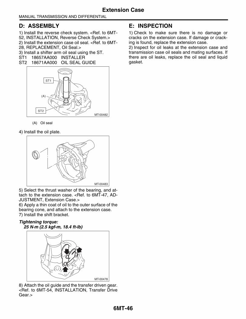
D: ASSEMBLY1) Install the reverse check system. <Ref. to 6MT-52, INSTALLATION, Reverse Check System.>2) Install the extension case oil seal. <Ref. to 6MT-28, REPLACEMENT, Oil Seal.>3) Install a shifter arm oil seal using the ST.ST1 18657AA000 INSTALLERST2 18671AA000 OIL SEAL GUIDE
4) Install the oil plate.
5) Select the thrust washer of the bearing, and at-tach to the extension case. <Ref. to 6MT-47, AD-JUSTMENT, Extension Case.>6) Apply a thin coat of oil to the outer surface of thebearing cone, and attach to the extension case.7) Install the shift bracket.
Tightening torque:25 N·m (2.5 kgf-m, 18.4 ft-lb)
8) Attach the oil guide and the transfer driven gear.<Ref. to 6MT-54, INSTALLATION, Transfer DriveGear.>
E: INSPECTION1) Check to make sure there is no damage orcracks on the extension case. If damage or crack-ing is found, replace the extension case.2) Inspect for oil leaks at the extension case andtransmission case oil seals and mating surfaces. Ifthere are oil leaks, replace the oil seal and liquidgasket.
(A) Oil seal
MT-00482
(A)
ST1
ST2
MT-00483
MT-00478
6MT-47
Extension CaseMANUAL TRANSMISSION AND DIFFERENTIAL
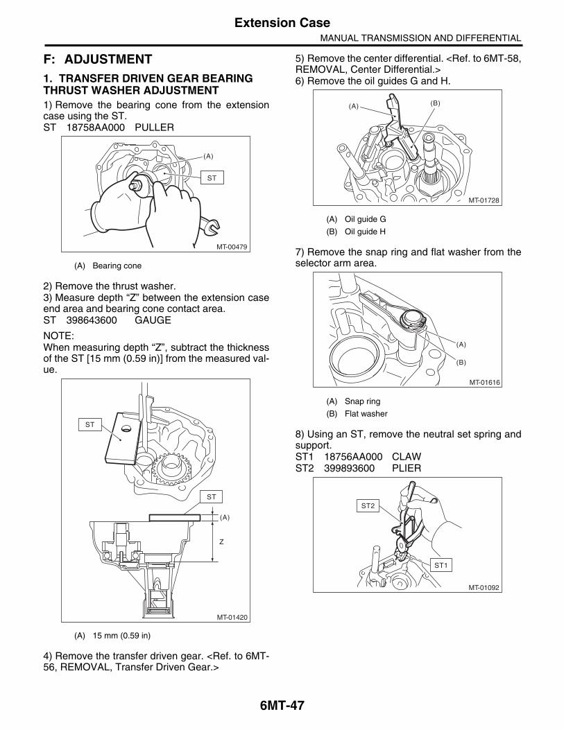
F: ADJUSTMENT1. TRANSFER DRIVEN GEAR BEARING THRUST WASHER ADJUSTMENT1) Remove the bearing cone from the extensioncase using the ST.ST 18758AA000 PULLER
2) Remove the thrust washer.3) Measure depth “Z” between the extension caseend area and bearing cone contact area.ST 398643600 GAUGE
NOTE:When measuring depth “Z”, subtract the thicknessof the ST [15 mm (0.59 in)] from the measured val-ue.
4) Remove the transfer driven gear. <Ref. to 6MT-56, REMOVAL, Transfer Driven Gear.>
5) Remove the center differential. <Ref. to 6MT-58,REMOVAL, Center Differential.>6) Remove the oil guides G and H.
7) Remove the snap ring and flat washer from theselector arm area.
8) Using an ST, remove the neutral set spring andsupport.ST1 18756AA000 CLAWST2 399893600 PLIER
(A) Bearing cone
(A) 15 mm (0.59 in)
MT-00479
(A)
ST
MT-01420
(A)
Z
ST
ST
(A) Oil guide G
(B) Oil guide H
(A) Snap ring
(B) Flat washer
MT-01728
(A) (B)
MT-01616
(B)
(A)
MT-01092
ST2
ST1
6MT-48
Extension CaseMANUAL TRANSMISSION AND DIFFERENTIAL
9) Lift the striking rod, and remove the spring pin.
10) Remove the selector arm No. 2 and the shifterarm.
11) Attach the bearing cone to the transfer drivengear.12) Set the ST.ST 18831AA000 GAUGE
13) Turn the transfer driven gear 10 or more timesto seat the bearing properly.
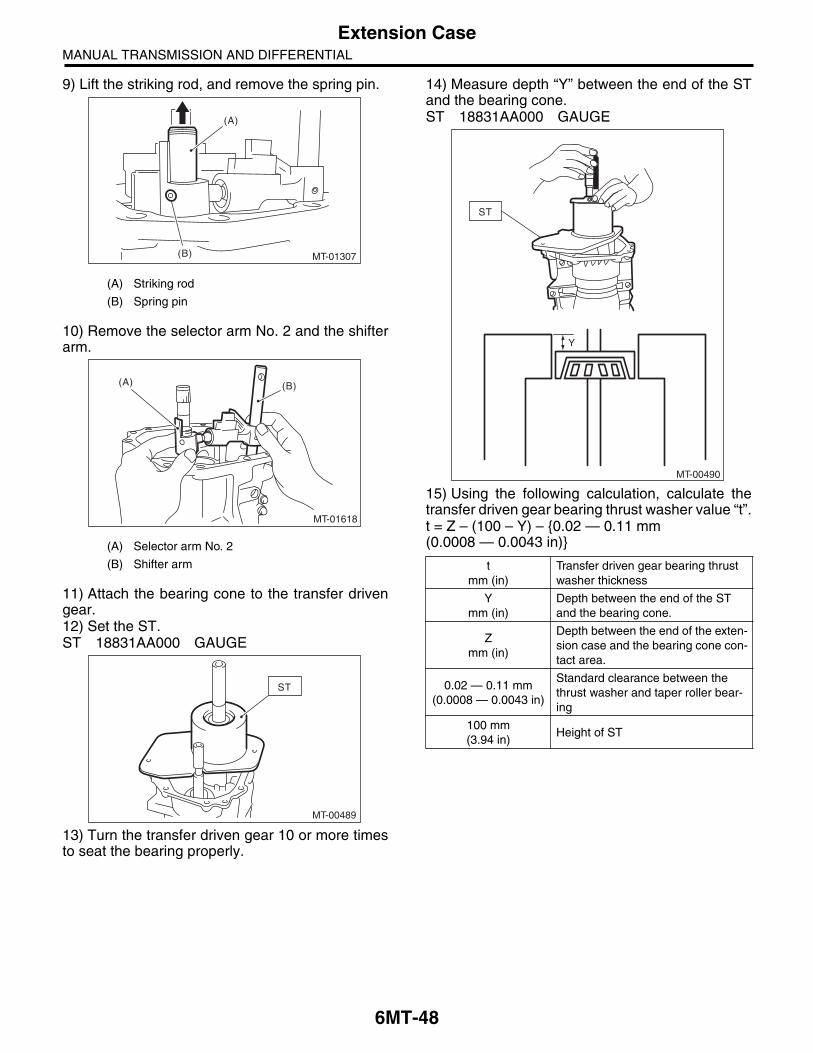
14) Measure depth “Y” between the end of the STand the bearing cone.ST 18831AA000 GAUGE
15) Using the following calculation, calculate thetransfer driven gear bearing thrust washer value “t”.t = Z – (100 – Y) – {0.02 — 0.11 mm (0.0008 — 0.0043 in)}
(A) Striking rod
(B) Spring pin
(A) Selector arm No. 2
(B) Shifter arm
MT-01307
(A)
(B)
(B)(A)
MT-01618
MT-00489
ST
tmm (in)
Transfer driven gear bearing thrust washer thickness
Ymm (in)
Depth between the end of the ST and the bearing cone.
Zmm (in)
Depth between the end of the exten-sion case and the bearing cone con-tact area.
0.02 — 0.11 mm(0.0008 — 0.0043 in)
Standard clearance between the thrust washer and taper roller bear-ing
100 mm(3.94 in)
Height of ST
MT-00490
Y
ST

6MT-49
Extension CaseMANUAL TRANSMISSION AND DIFFERENTIAL
16) Refer to the calculated value “t” to select theclosest thrust washer from the following table.
Standard clearance between the thrust washer and taper roller bearing
0.02 — 0.11 mm (0.0008 — 0.0043 in)
NOTE:Match to be within the standard clearance range.
17) Install the selector arm No. 2 and the shifterarm.
18) Install a new spring pin.
19) Using the ST, install the neutral set spring andsupport.ST1 18756AA000 CLAWST2 399893600 PLIER
20) Install the flat washer and snap ring to the se-lector arm area.
21) Install the center differential. <Ref. to 6MT-58,INSTALLATION, Center Differential.>
Thrust washer (50 × 61 × t)
Part No. Thickness t mm (in)
803050060 0.50 (0.0197)
803050061 0.55 (0.0217)
803050062 0.60 (0.0236)
803050063 0.65 (0.0256)
803050064 0.70 (0.0276)
803050065 0.75 (0.0295)
803050066 0.80 (0.0315)
803050067 0.85 (0.0335)
803050068 0.90 (0.0354)
803050069 0.95 (0.0374)
803050070 1.00 (0.0394)
803050071 1.05 (0.0413)
803050072 1.10 (0.0433)
803050073 1.15 (0.0453)
803050074 1.20 (0.0472)
803050075 1.25 (0.0492)
803050076 1.30 (0.0512)
803050077 1.35 (0.0531)
803050078 1.40 (0.0551)
803050079 1.45 (0.0570)
(A) Selector arm No. 2
(B) Shifter arm
(B)(A)
MT-01618
(A) Snap ring
(B) Flat washer
MT-01092
ST2
ST1
MT-01616
(B)
(A)

6MT-50
Extension CaseMANUAL TRANSMISSION AND DIFFERENTIAL
2. TRANSFER DRIVE GEAR THRUST WASHER SELECTION1) Measure height “Z” between the transmissioncase end area and ST.ST 398643600 GAUGE
2) Measure depth “Y” between the end of the STand the transfer drive gear.ST 398643600 GAUGE
3) Using the following calculation, calculate thetransfer drive gear thrust washer value “t”.t = {Y – 15 mm (0.59 in)} – {Z – 15 mm (0.59 in)} – 0.75 — 0.95 mm (0.030 — 0.037 in)
4) Refer to the calculated value “t” to select theclosest thrust washer from the following table.
Standard clearance between the thrust washer and transfer drive gear
0.75 — 0.95 mm (0.030 — 0.037 in)
NOTE:Match to be within the standard clearance range.
5) Install the selected thrust washer.
tmm (in)
Transfer drive gear thrust washer thickness
Ymm (in)
Depth between the end of the ST and the transfer drive gear
Zmm (in)
Height from the end of the transmis-sion case to the end of the ST.
0.75 — 0.95 mm(0.030 — 0.037 in)
Standard clearance between the thrust washer and transfer drive gear
15 mm (0.591 in) Thickness of ST
Z
ST
MT-00949
MT-01421
ST
ST
Y
Thrust washer (36.3 × 52 × t)
Part No. Thickness mm (in)
803036070 0.80 (0.0315)
803036071 0.95 (0.0374)
803036072 1.10 (0.0433)
803036073 1.25 (0.0492)
803036074 1.40 (0.0551)
803036075 0.65 (0.0256)
6MT-51
Reverse Check SystemMANUAL TRANSMISSION AND DIFFERENTIAL
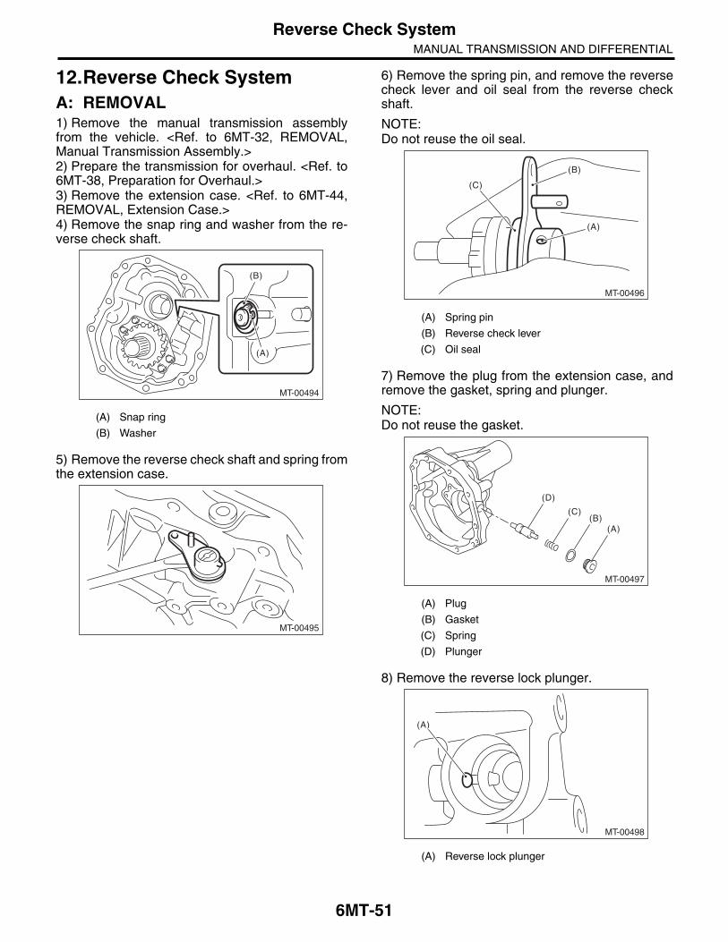
12.Reverse Check SystemA: REMOVAL1) Remove the manual transmission assemblyfrom the vehicle. <Ref. to 6MT-32, REMOVAL,Manual Transmission Assembly.>2) Prepare the transmission for overhaul. <Ref. to6MT-38, Preparation for Overhaul.>3) Remove the extension case. <Ref. to 6MT-44,REMOVAL, Extension Case.>4) Remove the snap ring and washer from the re-verse check shaft.
5) Remove the reverse check shaft and spring fromthe extension case.
6) Remove the spring pin, and remove the reversecheck lever and oil seal from the reverse checkshaft.
NOTE:Do not reuse the oil seal.
7) Remove the plug from the extension case, andremove the gasket, spring and plunger.
NOTE:Do not reuse the gasket.
8) Remove the reverse lock plunger.
(A) Snap ring
(B) Washer
MT-00494
(A)
(B)
MT-00495
(A) Spring pin
(B) Reverse check lever
(C) Oil seal
(A) Plug
(B) Gasket
(C) Spring
(D) Plunger
(A) Reverse lock plunger
MT-00496
(A)
(C)
(B)
MT-00497
(A)(B)
(C)
(D)
MT-00498
(A)
6MT-52
Reverse Check SystemMANUAL TRANSMISSION AND DIFFERENTIAL
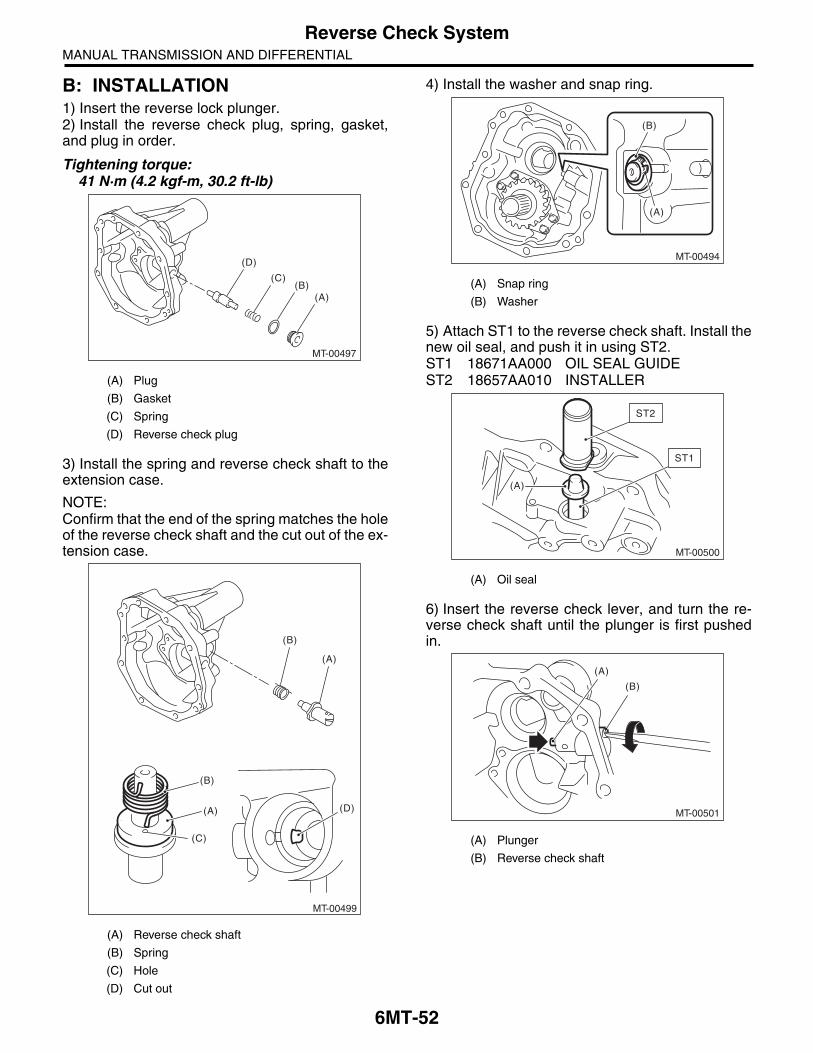
B: INSTALLATION1) Insert the reverse lock plunger.2) Install the reverse check plug, spring, gasket,and plug in order.
Tightening torque:41 N·m (4.2 kgf-m, 30.2 ft-lb)
3) Install the spring and reverse check shaft to theextension case.
NOTE:Confirm that the end of the spring matches the holeof the reverse check shaft and the cut out of the ex-tension case.
4) Install the washer and snap ring.
5) Attach ST1 to the reverse check shaft. Install thenew oil seal, and push it in using ST2.ST1 18671AA000 OIL SEAL GUIDEST2 18657AA010 INSTALLER
6) Insert the reverse check lever, and turn the re-verse check shaft until the plunger is first pushedin.
(A) Plug
(B) Gasket
(C) Spring
(D) Reverse check plug
(A) Reverse check shaft
(B) Spring
(C) Hole
(D) Cut out
MT-00497
(A)(B)
(C)
(D)
(A)
(A)
(C)
(D)
(B)
(B)
MT-00499
(A) Snap ring
(B) Washer
(A) Oil seal
(A) Plunger
(B) Reverse check shaft
MT-00494
(A)
(B)
MT-00500
(A)
ST2
ST1
MT-00501
(A)
(B)

6MT-53
Reverse Check SystemMANUAL TRANSMISSION AND DIFFERENTIAL
7) Match the hole of the reverse check lever andthe reverse check shaft, and attach the spring pin.
8) Check that the reverse check is operating cor-rectly. <Ref. to 6MT-53, INSPECTION, ReverseCheck System.>9) Install the extension case. <Ref. to 6MT-44, IN-STALLATION, Extension Case.>10) Install the manual transmission assembly to thevehicle. <Ref. to 6MT-34, INSTALLATION, ManualTransmission Assembly.>
C: INSPECTION1) Check that there is no damage on any parts.2) Check that the reverse check lever is operatingsmoothly.3) Inspect that there is no oil leak at the oil seal sec-tion of the reverse check shaft. If there is oil leak-age, replace the oil seal.4) Check the operation of the reverse check.
(1) When the reverse check lever is in the fol-lowing position, the plunger is pressed, or thegear can shift into reverse.
(2) When the reverse check lever is in the fol-lowing position, the plunger is not pressed, orthe gear cannot shift into reverse.
5) If not according to the standard, reassemble thereverse check system.
(A) Reverse check shaft
(B) Reverse check lever
(C) Hole
MT-00502(A) (B)
(C)
MT-00503
MT-00504

6MT-54
Transfer Drive GearMANUAL TRANSMISSION AND DIFFERENTIAL
13.Transfer Drive GearA: REMOVAL1) Remove the manual transmission assemblyfrom the vehicle. <Ref. to 6MT-32, REMOVAL,Manual Transmission Assembly.>2) Prepare the transmission for overhaul. <Ref. to6MT-38, Preparation for Overhaul.>3) Remove the extension case. <Ref. to 6MT-44,REMOVAL, Extension Case.>4) Remove the transfer drive gear.
B: INSTALLATION1) Install the transfer drive gear.
Tightening torque:25 N·m (2.5 kgf-m, 18.4 ft-lb)
2) When the ball bearing, transfer drive gear orsnap ring are replaced, select an appropriate thrustwasher for the transfer drive gear. <Ref. to 6MT-46,ASSEMBLY, Extension Case.>3) Install the extension case. <Ref. to 6MT-44, IN-STALLATION, Extension Case.>4) Install the manual transmission assembly to thevehicle. <Ref. to 6MT-34, INSTALLATION, ManualTransmission Assembly.>
C: DISASSEMBLY1) Remove the snap ring.
2) Remove the bearing using the ST.ST 499877000 RACE 4-5 INSTALLER
NOTE:Do not reuse the ball bearing.
MT-00505
MT-00505
MT-00506
MT-00507
ST

6MT-55
Transfer Drive GearMANUAL TRANSMISSION AND DIFFERENTIAL
D: ASSEMBLY1) Using the ST, install the ball bearing.ST1 499247400 INSTALLERST2 398497701 SEAT
2) Install the snap ring.
3) Inspect the clearance between the snap ring andthe ball bearing. <Ref. to 6MT-55, INSPECTION,Transfer Drive Gear.>
E: INSPECTION1) BearingReplace the bearings in the following cases.• Damage or rust on the bearings• Wear, or damage• The bearing does not rotate smoothly or an ab-normal noise is emitted.2) Drive gearReplace the drive gear in following case:• If the drive gear tooth surface and shaft are ex-cessively damaged or broken.3) Measure the clearance between the snap ringand ball bearing inner race with a thickness gauge.
Standard clearance between the snap ring and inner race:
0 — 0.15 mm (0 — 0.0059 in)
4) If the measurement is out of specifications, rese-lect an appropriate snap ring.
After replacing the snap ring, reinspect the clear-ance.
MT-00508
ST2
ST1
MT-00506
Thrust washer
Part No. Thickness mm (in)
805045050 1.76 (0.069)
805045060 1.88 (0.074)
805045070 2.00 (0.079)
MT-00509

6MT-56
Transfer Driven GearMANUAL TRANSMISSION AND DIFFERENTIAL
14.Transfer Driven GearA: REMOVAL1) Remove the manual transmission assemblyfrom the vehicle. <Ref. to 6MT-32, REMOVAL,Manual Transmission Assembly.>2) Prepare the transmission for overhaul. <Ref. to6MT-38, Preparation for Overhaul.>3) Remove the extension case. <Ref. to 6MT-44,REMOVAL, Extension Case.>4) Remove the transfer driven gear.
B: INSTALLATION1) Install the transfer driven gear.
2) When the bearing or the transfer driven gear isreplaced, select an appropriate thrust washer forthe transfer driven gear. <Ref. to 6MT-47, AD-JUSTMENT, Extension Case.>3) Install the extension case. <Ref. to 6MT-44, IN-STALLATION, Extension Case.>4) Install the manual transmission assembly to thevehicle. <Ref. to 6MT-34, INSTALLATION, ManualTransmission Assembly.>
C: DISASSEMBLY1) Using the ST, remove the roller bearing (exten-sion case side).ST 498515700 REMOVER
2) Using the ST, remove the roller bearing (trans-mission case side).ST1 899858600 REMOVERST2 899864100 REMOVER
MT-00951
MT-00951
MT-00511
ST
MT-00512
ST2
ST1

6MT-57
Transfer Driven GearMANUAL TRANSMISSION AND DIFFERENTIAL
D: ASSEMBLY1) Using the ST, install the roller bearing (extensioncase side).ST1 398177700 INSTALLERST2 899864100 REMOVER
CAUTION:Do not apply pressure in excess of 10 kN (1 ton,1.1 US ton, 1.0 Imp ton).
2) Using the ST, install the roller bearing (transmis-sion case side).ST 499757002 INSTALLER
CAUTION:Do not apply pressure in excess of 10 kN (1 ton,1.1 US ton, 1.0 Imp ton).
E: INSPECTION1) BearingReplace the bearings in the following cases.• Damage or rust on the bearings• Wear, or damage• After applying transmission gear oil, bearingdoes not rotate smoothly or an abnormal noise isemitted.2) Driven gearReplace the driven gear in the following cases.• If the driven gear tooth surface and shaft are ex-cessively damaged or broken.
(A) Roller bearing
(A) Roller bearing
MT-00513
(A) ST1
ST2
MT-00514
(A)
ST

6MT-58
Center DifferentialMANUAL TRANSMISSION AND DIFFERENTIAL
15.Center DifferentialA: REMOVAL1) Remove the manual transmission case from thevehicle. <Ref. to 6MT-32, REMOVAL, Manual Transmission Assembly.>2) Prepare the transmission for overhaul. <Ref. to6MT-38, Preparation for Overhaul.>3) Remove the extension case. <Ref. to 6MT-44,REMOVAL, Extension Case.>4) Remove the transfer driven gear. <Ref. to 6MT-56, REMOVAL, Transfer Driven Gear.>5) Disconnect the center differential connector.6) Remove the thrust washer and center differen-tial.
7) Remove the needle bearing.
B: INSTALLATION1) Install the needle bearing.
2) Install the thrust washer and center differential.
3) When replacing the center differential, selectand install the appropriate transfer drive gear andthrust washer. <Ref. to 6MT-47, ADJUSTMENT,Extension Case.>4) Connect the center differential connector, andaffix to the oil guide.5) Install the transfer driven gear. <Ref. to 6MT-56,INSTALLATION, Transfer Driven Gear.>6) Install the extension case. <Ref. to 6MT-44, IN-STALLATION, Extension Case.>7) Install the manual transmission case assemblyto the vehicle. <Ref. to 6MT-34, INSTALLATION,Manual Transmission Assembly.>
C: INSPECTIONCheck that there is no damage on the center differ-ential. Replace if damaged.
(A) Thrust washer
(B) Center differential
(A)(B)
MT-00952
MT-00516
(A) Thrust washer
(B) Center differential
MT-00516
(A)(B)
MT-00952
6MT-59
Transmission CaseMANUAL TRANSMISSION AND DIFFERENTIAL
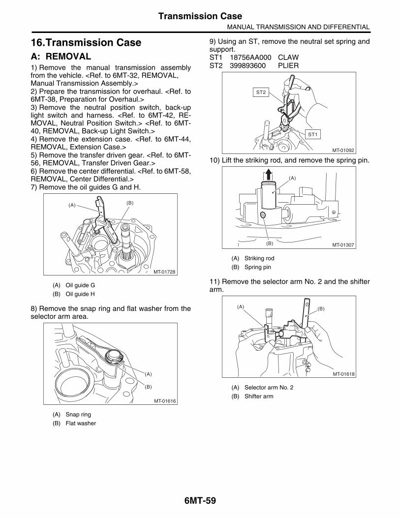
16.Transmission CaseA: REMOVAL1) Remove the manual transmission assemblyfrom the vehicle. <Ref. to 6MT-32, REMOVAL, Manual Transmission Assembly.>2) Prepare the transmission for overhaul. <Ref. to6MT-38, Preparation for Overhaul.>3) Remove the neutral position switch, back-uplight switch and harness. <Ref. to 6MT-42, RE-MOVAL, Neutral Position Switch.> <Ref. to 6MT-40, REMOVAL, Back-up Light Switch.>4) Remove the extension case. <Ref. to 6MT-44,REMOVAL, Extension Case.>5) Remove the transfer driven gear. <Ref. to 6MT-56, REMOVAL, Transfer Driven Gear.>6) Remove the center differential. <Ref. to 6MT-58,REMOVAL, Center Differential.>7) Remove the oil guides G and H.
8) Remove the snap ring and flat washer from theselector arm area.
9) Using an ST, remove the neutral set spring andsupport.ST1 18756AA000 CLAWST2 399893600 PLIER
10) Lift the striking rod, and remove the spring pin.
11) Remove the selector arm No. 2 and the shifterarm.
(A) Oil guide G
(B) Oil guide H
(A) Snap ring
(B) Flat washer
MT-01728
(A) (B)
MT-01616
(B)
(A)
(A) Striking rod
(B) Spring pin
(A) Selector arm No. 2
(B) Shifter arm
MT-01092
ST2
ST1
MT-01307
(A)
(B)
(B)(A)
MT-01618

6MT-60
Transmission CaseMANUAL TRANSMISSION AND DIFFERENTIAL
12) Remove the transfer bearing holder.
NOTE:Using a general tool may cause damage. Removethe bolt using the ST.ST 18663AA000 SOCKET
13) Remove the thrust washer on the main shaftsection.14) Remove the driven gear assembly shim andspacer.
15) Remove the snap ring.
16) Remove the pilot bolt.
17) Remove the holder reverse bolt.
18) Remove the transmission case.
NOTE:If the oil guide is caught between the shift fork, itmay be difficult to remove the transmission case.Move the oil guide, then remove. Do not pull on thetransmission case with excessive force.
19) Remove any remaining liquid gasket from thetransmission case and adapter plate.
(A) Driven gear ASSY
MT-01619
(A)
MT-00526
MT-00527
MT-00528
MT-00529
MT-01711

6MT-61
Transmission CaseMANUAL TRANSMISSION AND DIFFERENTIAL
B: INSTALLATION1) Check that the shifter fork and the interlock blockare both shifted into the neutral position. If they arenot, shift into the neutral position.
2) Apply liquid gasket to the adapter plate.
Liquid gasket:THREE BOND 1215 (Part No. 004403007) or equivalent
3) Install the transmission case.
4) By inspecting from the pilot bolt attachment hole,check that the interlock block and the reverse inter-lock block aligned in the neutral position. If notaligned in neutral, remove the transmission case,and shift the shifter fork and interlock block to theneutral position.
5) Temporarily attach the pilot bolt with a new gas-ket.6) Affix the transmission case with the bolts andnuts.
Tightening torque:50 N·m (5.1 kgf-m, 36.9 ft-lb)
7) Tighten the pilot bolt.
Tightening torque:34 N·m (3.5 kgf-m, 25.1 ft-lb)
8) Tighten the holder reverse bolt.
Tightening torque:25 N·m (2.5 kgf-m, 18.4 ft-lb)
(A) Striking rod
(B) Reverse interlock block
(C) Interlock block
(A)
(C)
(B)
MT-01620
MT-00532
(A) Interlock block
(B) Reverse interlock block
MT-00533
(A)
(B)

6MT-62
Transmission CaseMANUAL TRANSMISSION AND DIFFERENTIAL
9) Install the snap ring, washer and collar of thedriven gear assembly.
10) Attach the thrust washer to the main shaft.11) Install the transfer bearing holder.
Tightening torque:25 N·m (2.5 kgf-m, 18.4 ft-lb)
ST 18663AA000 SOCKET
12) When replacing the transfer bearing holder, se-lect the appropriate transfer driven gear and thrustwasher, and install to the extension case. <Ref. to6MT-47, ADJUSTMENT, Extension Case.>
13) Install the selector arm No. 2 and the shifterarm.
14) Install a new spring pin.15) Using the ST, install the neutral set spring.ST1 18756AA000 CLAWST2 399893600 PLIER
16) Install the snap ring and flat washer to the se-lector arm area.
(A) Washer
(B) Snap ring
(C) Collar
(D) Washer
(C)
(B)
(A)
(C)
(B) (D)
(A)
MT-01621
MT-01619
(A) Selector arm No. 2
(B) Shifter arm
(A) Snap ring
(B) Flat washer
(B)(A)
MT-01618
MT-01092
ST2
ST1
MT-01616
(B)
(A)

6MT-63
Transmission CaseMANUAL TRANSMISSION AND DIFFERENTIAL
17) Install the oil guides G and H.
18) Install the center differential. <Ref. to 6MT-58,INSTALLATION, Center Differential.>19) Install the transfer driven gear. <Ref. to 6MT-56, INSTALLATION, Transfer Driven Gear.>20) Install the extension case. <Ref. to 6MT-44, IN-STALLATION, Extension Case.>21) Install the neutral position switch, back-up lightswitch and harness. <Ref. to 6MT-42, INSTALLA-TION, Neutral Position Switch.> <Ref. to 6MT-40,INSTALLATION, Back-up Light Switch.>22) Install the manual transmission assembly to thevehicle. <Ref. to 6MT-34, INSTALLATION, ManualTransmission Assembly.>
C: DISASSEMBLY1) Remove the transmission harness from thetransmission case.
NOTE:Remove the connector by disengaging the connec-tor claw from the inside of the transmission. 2) Remove the oil guides C, D, E, F and harnessbracket.
3) Remove the oil pan.
4) Remove any remaining liquid gasket from thetransmission case and oil pan.
(A) Oil guide G
(B) Oil guide H
MT-01728
(A) (B)
(A) Oil guide C
(B) Oil guide D
(C) Oil guide E
(D) Oil guide F
(E) Harness bracket
(A)
(B)
(C)
(D)
MT-01712
(E)
MT-00539

6MT-64
Transmission CaseMANUAL TRANSMISSION AND DIFFERENTIAL
D: ASSEMBLY1) Apply liquid gasket to the oil pan.
Liquid gasket:THREE BOND 1215 (Part No. 004403007) or equivalent
2) Install the oil pan.
Tightening torque:6.4 N·m (0.7 kgf-m, 4.7 ft-lb)
3) Install the oil guides C, D, E, F and harnessbracket.
Tightening torque:T1: 16 N·m (1.6 kgf-m, 11.8 ft-lb)T2: 18 N·m (1.8 kgf-m, 13.3 ft-lb)
MT-00541
MT-00539
(A) Oil guide C
(B) Oil guide D
(C) Oil guide E
(D) Oil guide F
(E) Harness bracket
(A)
(B)
(C)
(D)
MT-01713
(E)
T1T2

6MT-65
Transmission CaseMANUAL TRANSMISSION AND DIFFERENTIAL
4) Attach the transmission harness to the transmis-sion.
NOTE:Install the transmission harness connector by align-ing the protrusions of the transmission and trans-mission harness connector.
E: INSPECTION1) If the sludge is accumulated in the oil pan, use awaste cloth to wipe it off completely.2) Check that there is no damage on any parts. Re-place damaged parts with new parts.
(A) Protrusion
(B) Transmission harness connectors
MT-01777
(B)
(A)
6MT-66
Main Shaft AssemblyMANUAL TRANSMISSION AND DIFFERENTIAL
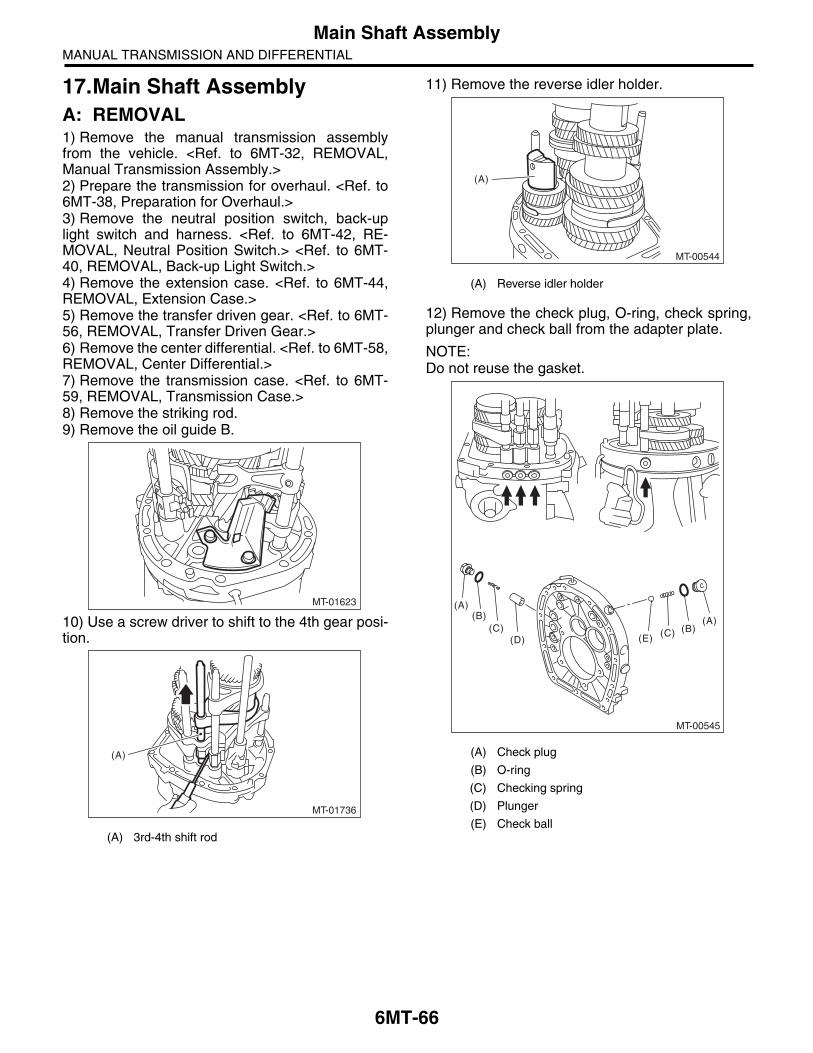
17.Main Shaft AssemblyA: REMOVAL1) Remove the manual transmission assemblyfrom the vehicle. <Ref. to 6MT-32, REMOVAL,Manual Transmission Assembly.>2) Prepare the transmission for overhaul. <Ref. to6MT-38, Preparation for Overhaul.>3) Remove the neutral position switch, back-uplight switch and harness. <Ref. to 6MT-42, RE-MOVAL, Neutral Position Switch.> <Ref. to 6MT-40, REMOVAL, Back-up Light Switch.>4) Remove the extension case. <Ref. to 6MT-44,REMOVAL, Extension Case.>5) Remove the transfer driven gear. <Ref. to 6MT-56, REMOVAL, Transfer Driven Gear.>6) Remove the center differential. <Ref. to 6MT-58,REMOVAL, Center Differential.>7) Remove the transmission case. <Ref. to 6MT-59, REMOVAL, Transmission Case.>8) Remove the striking rod.9) Remove the oil guide B.
10) Use a screw driver to shift to the 4th gear posi-tion.
11) Remove the reverse idler holder.
12) Remove the check plug, O-ring, check spring,plunger and check ball from the adapter plate.
NOTE:Do not reuse the gasket.
(A) 3rd-4th shift rod
MT-01623
MT-01736
(A)
(A) Reverse idler holder
(A) Check plug
(B) O-ring
(C) Checking spring
(D) Plunger
(E) Check ball
MT-00544
(A)
(D) (E)
(A)
(A)(B)(B)(C) (C)
MT-00545
6MT-67
Main Shaft AssemblyMANUAL TRANSMISSION AND DIFFERENTIAL
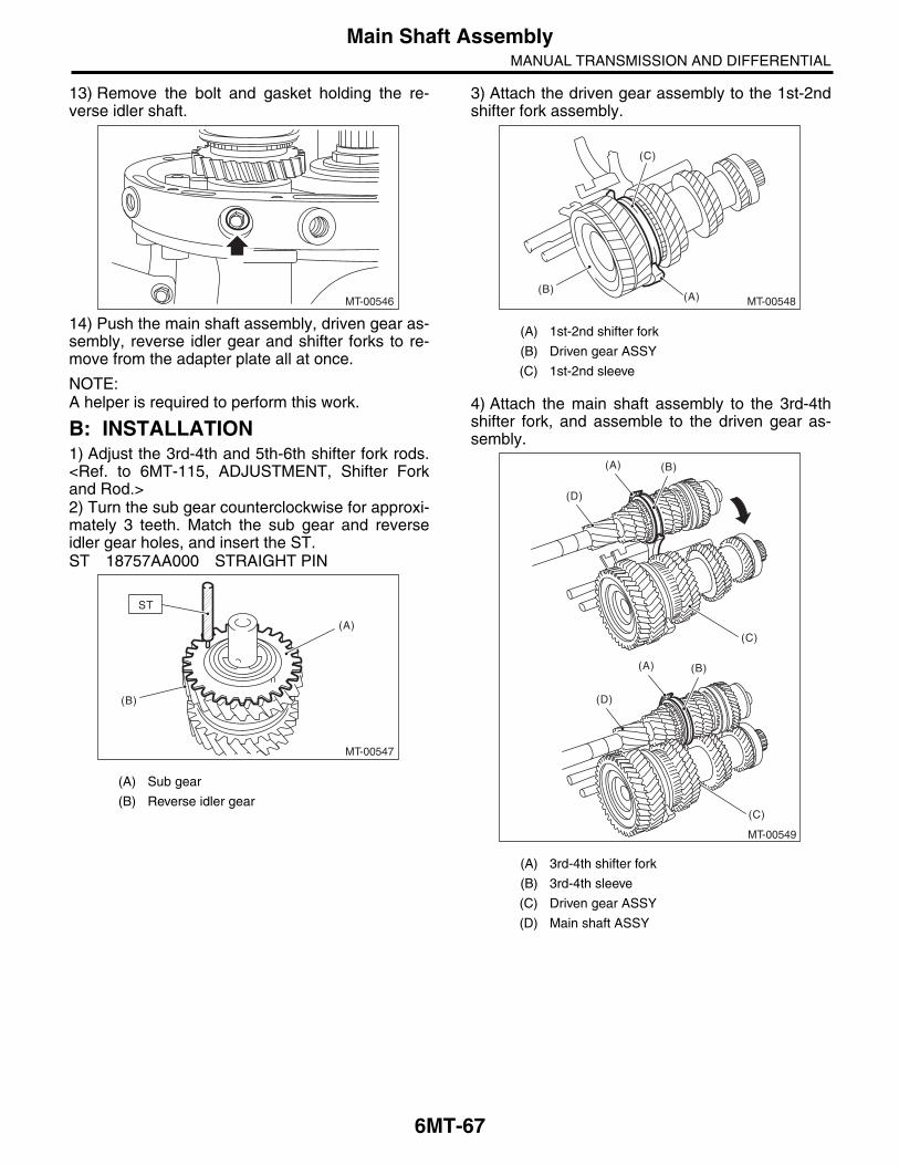
13) Remove the bolt and gasket holding the re-verse idler shaft.
14) Push the main shaft assembly, driven gear as-sembly, reverse idler gear and shifter forks to re-move from the adapter plate all at once.
NOTE:A helper is required to perform this work.
B: INSTALLATION1) Adjust the 3rd-4th and 5th-6th shifter fork rods.<Ref. to 6MT-115, ADJUSTMENT, Shifter Forkand Rod.>2) Turn the sub gear counterclockwise for approxi-mately 3 teeth. Match the sub gear and reverseidler gear holes, and insert the ST.ST 18757AA000 STRAIGHT PIN
3) Attach the driven gear assembly to the 1st-2ndshifter fork assembly.
4) Attach the main shaft assembly to the 3rd-4thshifter fork, and assemble to the driven gear as-sembly.
(A) Sub gear
(B) Reverse idler gear
MT-00546
MT-00547
(A)
(B)
ST
(A) 1st-2nd shifter fork
(B) Driven gear ASSY
(C) 1st-2nd sleeve
(A) 3rd-4th shifter fork
(B) 3rd-4th sleeve
(C) Driven gear ASSY
(D) Main shaft ASSY
MT-00548(A)(B)
(C)
MT-00549
(C)
(A) (B)
(C)
(D)
(D)
(A) (B)
6MT-68
Main Shaft AssemblyMANUAL TRANSMISSION AND DIFFERENTIAL
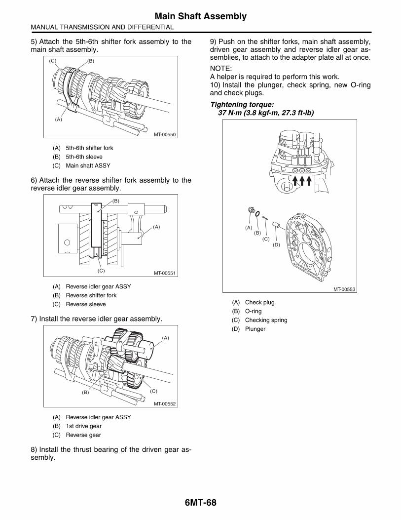
5) Attach the 5th-6th shifter fork assembly to themain shaft assembly.
6) Attach the reverse shifter fork assembly to thereverse idler gear assembly.
7) Install the reverse idler gear assembly.
8) Install the thrust bearing of the driven gear as-sembly.
9) Push on the shifter forks, main shaft assembly,driven gear assembly and reverse idler gear as-semblies, to attach to the adapter plate all at once.
NOTE:A helper is required to perform this work.10) Install the plunger, check spring, new O-ringand check plugs.
Tightening torque:37 N·m (3.8 kgf-m, 27.3 ft-lb)
(A) 5th-6th shifter fork
(B) 5th-6th sleeve
(C) Main shaft ASSY
(A) Reverse idler gear ASSY
(B) Reverse shifter fork
(C) Reverse sleeve
(A) Reverse idler gear ASSY
(B) 1st drive gear
(C) Reverse gear
MT-00550
(B)
(A)
(C)
MT-00551
(A)
(B)
(C)
MT-00552
(B)
(A)
(C)
(A) Check plug
(B) O-ring
(C) Checking spring
(D) Plunger
MT-00553
(D)
(A)(B)
(C)
6MT-69
Main Shaft AssemblyMANUAL TRANSMISSION AND DIFFERENTIAL
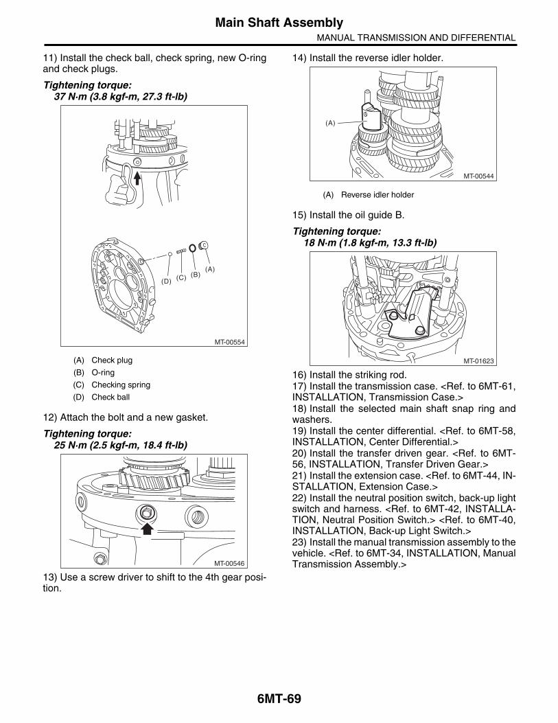
11) Install the check ball, check spring, new O-ringand check plugs.
Tightening torque:37 N·m (3.8 kgf-m, 27.3 ft-lb)
12) Attach the bolt and a new gasket.
Tightening torque:25 N·m (2.5 kgf-m, 18.4 ft-lb)
13) Use a screw driver to shift to the 4th gear posi-tion.
14) Install the reverse idler holder.
15) Install the oil guide B.
Tightening torque:18 N·m (1.8 kgf-m, 13.3 ft-lb)
16) Install the striking rod.17) Install the transmission case. <Ref. to 6MT-61,INSTALLATION, Transmission Case.>18) Install the selected main shaft snap ring andwashers.19) Install the center differential. <Ref. to 6MT-58,INSTALLATION, Center Differential.>20) Install the transfer driven gear. <Ref. to 6MT-56, INSTALLATION, Transfer Driven Gear.>21) Install the extension case. <Ref. to 6MT-44, IN-STALLATION, Extension Case.>22) Install the neutral position switch, back-up lightswitch and harness. <Ref. to 6MT-42, INSTALLA-TION, Neutral Position Switch.> <Ref. to 6MT-40,INSTALLATION, Back-up Light Switch.>23) Install the manual transmission assembly to thevehicle. <Ref. to 6MT-34, INSTALLATION, ManualTransmission Assembly.>
(A) Check plug
(B) O-ring
(C) Checking spring
(D) Check ball
MT-00554
(D)
(A)(B)(C)
MT-00546
(A) Reverse idler holder
MT-00544
(A)
MT-01623

6MT-70
Main Shaft AssemblyMANUAL TRANSMISSION AND DIFFERENTIAL
C: DISASSEMBLYNOTE:Individual sleeves and hubs meet at a specified po-sition. Before disassembly, mark the meeting posi-tion of the sleeve and hub.1) Affix the ST to the work table.ST 18664AA000 BASE2) Flatten the locknut tab.3) Set the main shaft assembly to the ST, and re-move the lock nut and washer.ST1 18665AA000 HOLDERST2 18664AA000 BASE
NOTE:Use a 38 mm socket wrench.
4) Remove the main shaft assembly from the ST.
5) Set the ST1 to the 6th drive gear, and use apress to remove the taper roller bearing, bushingand 6th drive gear.ST1 18722AA010 REMOVERST2 899864100 REMOVER
6) Remove the 5th-6th sleeve, 6th needle bearingand 6th baulk ring.
MT-00556
ST2
ST1
(A) Taper roller bearing
(B) Bushing
(C) 6th drive gear
(A) Needle bearing
(B) 6th baulk ring
(C) 5th-6th sleeve
MT-00557
(A)
(B) (C)
ST1
ST2
ST1
(A)
(B)
(C)
MT-00558
6MT-71
Main Shaft AssemblyMANUAL TRANSMISSION AND DIFFERENTIAL
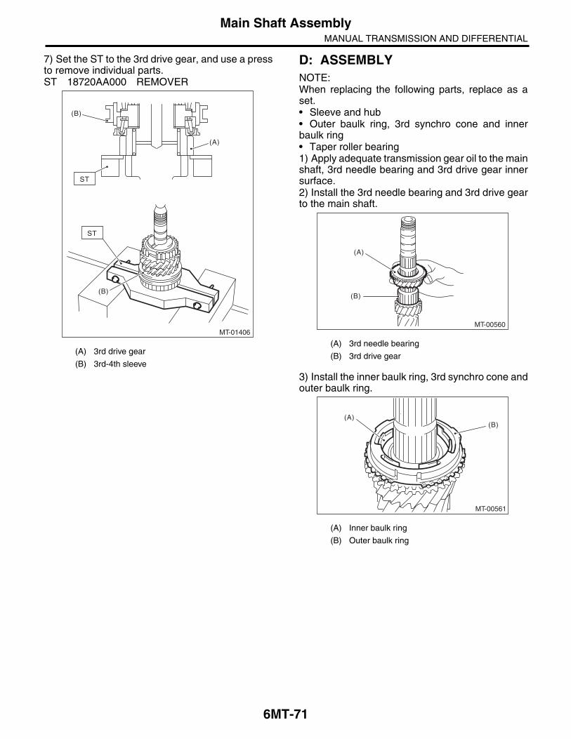
7) Set the ST to the 3rd drive gear, and use a pressto remove individual parts.ST 18720AA000 REMOVER
D: ASSEMBLYNOTE:When replacing the following parts, replace as aset.• Sleeve and hub• Outer baulk ring, 3rd synchro cone and innerbaulk ring• Taper roller bearing1) Apply adequate transmission gear oil to the mainshaft, 3rd needle bearing and 3rd drive gear innersurface.2) Install the 3rd needle bearing and 3rd drive gearto the main shaft.
3) Install the inner baulk ring, 3rd synchro cone andouter baulk ring.
(A) 3rd drive gear
(B) 3rd-4th sleeve
(A)
ST
(B)
(B)
ST
MT-01406
(A) 3rd needle bearing
(B) 3rd drive gear
(A) Inner baulk ring
(B) Outer baulk ring
MT-00560
(A)
(B)
(A)(B)
MT-00561

6MT-72
Main Shaft AssemblyMANUAL TRANSMISSION AND DIFFERENTIAL
NOTE:Install the 3rd synchro cone by aligning the protru-sion of the 3rd synchro cone with the hole on the3rd drive gear.
4) Install the 3rd-4th hub and 4th bushing.(1) Being careful of the install direction of the3rd-4th hub, set to the main shaft.
(2) Being careful not to cover the oil holes of themain shaft and 4th bushing, attach to the mainshaft.
(A) Main shaft
(B) 3rd-4th hub
(C) 3rd drive gear
MT-01501
MT-00884
(A)
(B)
(C)(A) 4th bushing
(B) 3rd-4th hub
(C) 4th bushing oil hole
(D) Main shaft oil hole
MT-00885
(A)
(B)
A
(D)
(C)
A
(C)
(C) (D)
A - A
(A)

6MT-73
Main Shaft AssemblyMANUAL TRANSMISSION AND DIFFERENTIAL
(3) Using the ST, push in to the 3rd-4th hub and4th bushing all at once.
ST1 18651AA000 INSTALLERST2 398177700 INSTALLER
CAUTION:Do not apply pressure in excess of 40 kN (4.0 ton, 4.4 US ton, 3.9 Imp ton).
NOTE:When pushing into the 3rd-4th hub and 4th bush-ing, move the outer baulk ring to match the protru-sion of the outer baulk ring and the cut out on the3rd-4th bushing.
5) Make sure that the 3rd drive gear can be turnedsmoothly by hand. If it does not turn smoothly, re-assemble.
6) Attach the 3rd-4th shifting insert key at the ap-propriate position of the 3rd-4th sleeve.
NOTE:• The location angle of each shifting insert key is120°.• Refer to the following figure to install the shiftinginsert key.
7) Attach the 3rd-4th sleeve to the 3rd-4th hub.
NOTE:• There is an identification groove on the 3rd-4thsleeve.• Place the groove towards the 3rd drive gear, andattach the 3rd-4th sleeve.
(A) 3rd-4th hub
(B) Outer baulk ring
(C) Cut out on the 3rd-4th hub
(D) Protrusion of the outer baulk ring
(E) 4th bushing
MT-00555
(D)
(C)
(A)
(E)
(E)
(A)
(B)
ST1
ST2
(A) Attach the straight part of the shifting insert key to the sleeve convex portion.
(B) Shifting insert key
(C) 3rd-4th sleeve
(D) 3rd-4th shifting insert key
(A) 3rd drive gear
(B) 3rd-4th sleeve identification groove (1)
(D)
(C)
MT-01641
(A)
(B)
(A)
MT-00563
(A)
(B)

6MT-74
Main Shaft AssemblyMANUAL TRANSMISSION AND DIFFERENTIAL
8) Install the 4th baulk ring.
9) Apply adequate transmission gear oil to the mainshaft, 4th needle bearing and 4th drive gear innersurface.10) Install the 4th needle bearing and 4th drivegear.
11) Install the 5th bushing.(1) Being careful not to cover the oil holes of themain shaft and 5th bushing, attach to the mainshaft.
(2) Using the ST, push into the 5th bushing.ST1 18651AA000 INSTALLERST2 398177700 INSTALLER
CAUTION:Do not apply pressure in excess of 40 kN (4.0 ton, 4.4 US ton, 3.9 Imp ton).
12) Make sure that the 4th drive gear can be turnedsmoothly by hand. If it does not turn smoothly, re-assemble.13) Apply adequate transmission gear oil to themain shaft, 5th needle bearing and 5th drive gearinner surface.
(A) 4th needle bearing
(B) 4th drive gear
MT-00564
MT-00565
(A)
(B)
(A) 5th bushing
(B) Main shaft oil hole
(C) Main shaft
(D) 5th bushing oil hole
(E) 4th drive gear
MT-00566
(C)
(A)
A - A
(C) (B)
(A)
A
(D)
(C)
(E)(B)
A
MT-00567
ST1
ST2
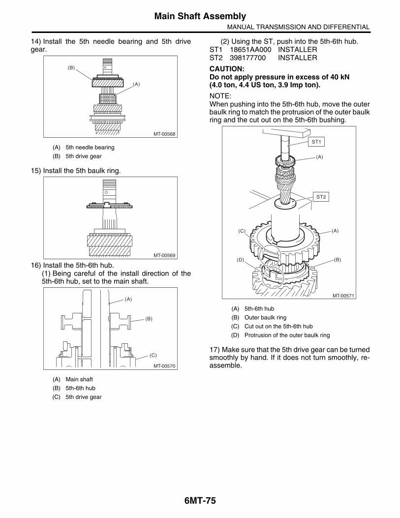
6MT-75
Main Shaft AssemblyMANUAL TRANSMISSION AND DIFFERENTIAL
14) Install the 5th needle bearing and 5th drivegear.
15) Install the 5th baulk ring.
16) Install the 5th-6th hub.(1) Being careful of the install direction of the5th-6th hub, set to the main shaft.
(2) Using the ST, push into the 5th-6th hub.ST1 18651AA000 INSTALLERST2 398177700 INSTALLER
CAUTION:Do not apply pressure in excess of 40 kN (4.0 ton, 4.4 US ton, 3.9 Imp ton).
NOTE:When pushing into the 5th-6th hub, move the outerbaulk ring to match the protrusion of the outer baulkring and the cut out on the 5th-6th bushing.
17) Make sure that the 5th drive gear can be turnedsmoothly by hand. If it does not turn smoothly, re-assemble.
(A) 5th needle bearing
(B) 5th drive gear
(A) Main shaft
(B) 5th-6th hub
(C) 5th drive gear
MT-00568
(A)
(B)
MT-00569
MT-00570
(A)
(B)
(C)
(A) 5th-6th hub
(B) Outer baulk ring
(C) Cut out on the 5th-6th hub
(D) Protrusion of the outer baulk ring
MT-00571
(D)
(C)
(B)
(A)
(A)
ST1
ST2

6MT-76
Main Shaft AssemblyMANUAL TRANSMISSION AND DIFFERENTIAL
18) Attach the 5th-6th shifting insert key at the ap-propriate position of the 5th-6th sleeve.
NOTE:• The location angle of each shifting insert key is120°.• Refer to the following figure to install the shiftinginsert key.
19) Attach the 5th-6th sleeve to the 5th-6th hub.
NOTE:• There are two identification grooves on the 5th-6th sleeve.• Place the grooves towards the 5th drive gear,and attach the 5th-6th sleeve.
20) Install the 6th baulk ring.
21) Apply adequate transmission gear oil to themain shaft, 6th needle bearing and 6th drive gearinner surface.22) Install the 6th drive gear.
23) Install the 6th needle bearing.
24) Being careful not to cover the oil holes of the6th bushing and the main shaft, set the 6th bushingto the main shaft.
(A) Attach the straight part of the shifting insert key to the sleeve convex portion.
(B) Shifting insert key
(C) 5th-6th sleeve
(D) Shifting insert key
(A) 5th drive gear
(B) 5th-6th sleeve identification groove (2)
(D)
(C)
MT-01641
(A)
(B)
(A)
MT-00572
(A)
(B)
(A) 6th bushing oil hole
(B) Main shaft oil hole
MT-00573
MT-00574
MT-00575
MT-00576
(A)
(A) (B)
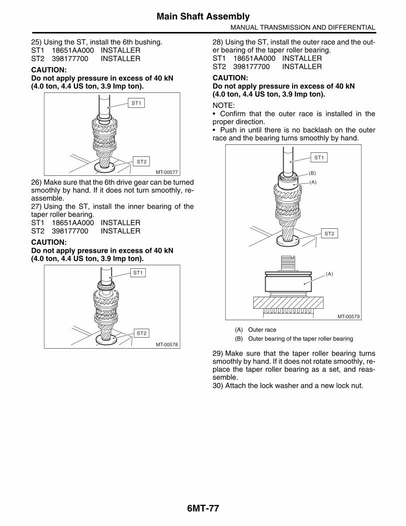
6MT-77
Main Shaft AssemblyMANUAL TRANSMISSION AND DIFFERENTIAL
25) Using the ST, install the 6th bushing.ST1 18651AA000 INSTALLERST2 398177700 INSTALLER
CAUTION:Do not apply pressure in excess of 40 kN (4.0 ton, 4.4 US ton, 3.9 Imp ton).
26) Make sure that the 6th drive gear can be turnedsmoothly by hand. If it does not turn smoothly, re-assemble.27) Using the ST, install the inner bearing of thetaper roller bearing.ST1 18651AA000 INSTALLERST2 398177700 INSTALLER
CAUTION:Do not apply pressure in excess of 40 kN (4.0 ton, 4.4 US ton, 3.9 Imp ton).
28) Using the ST, install the outer race and the out-er bearing of the taper roller bearing.ST1 18651AA000 INSTALLERST2 398177700 INSTALLER
CAUTION:Do not apply pressure in excess of 40 kN (4.0 ton, 4.4 US ton, 3.9 Imp ton).
NOTE:• Confirm that the outer race is installed in theproper direction.• Push in until there is no backlash on the outerrace and the bearing turns smoothly by hand.
29) Make sure that the taper roller bearing turnssmoothly by hand. If it does not rotate smoothly, re-place the taper roller bearing as a set, and reas-semble.30) Attach the lock washer and a new lock nut.
MT-00577
ST1
ST2
MT-00578
ST1
ST2(A) Outer race
(B) Outer bearing of the taper roller bearing
MT-00579
(B)
(A)
(A)
ST2
ST1

6MT-78
Main Shaft AssemblyMANUAL TRANSMISSION AND DIFFERENTIAL
31) Set the main shaft assembly to the ST, andtighten the lock nut.ST1 18665AA000 HOLDERST2 18664AA000 BASE
Tightening torque:392 N·m (40.0 kgf-m, 289.1 ft-lb)
32) Using the ST, crimp the lock nut in 4 locations,with dimensions within A 27 0.3 mm (1.06 0.01 in).ST 18668AA000 PUNCH
NOTE:Do not damage the crimp area of the lock nut.
E: INSPECTIONDisassembled parts should be washed clean firstwith cleaning solvent and then inspected carefully.1) BearingReplace the bearings in the following cases.• Wear, rusting or damage of the bearings• The bearing does not rotate smoothly or an ab-normal noise is emitted when turning.• When the bearing has other defects2) Bushing (each gear)Replace the bushing in following cases.• The sliding surface is damaged or abnormallyworn.3) GearReplace gears in the following cases.• The gear teeth surface is damaged or excessive-ly worn.• If the contact area of the baulk ring is damaged.• If the inner face of the gear is worn.4) Baulk ring, synchro coneReplace the baulk ring and synchro cone in follow-ing cases:• Wear, rusting or damage of the baulk ring5) Shifting insert keyReplace the shifting insert key if deformed, exces-sively worn or defective in any way.
MT-00556
ST2
ST1
MT-00580
A
A
ST
MT-00581
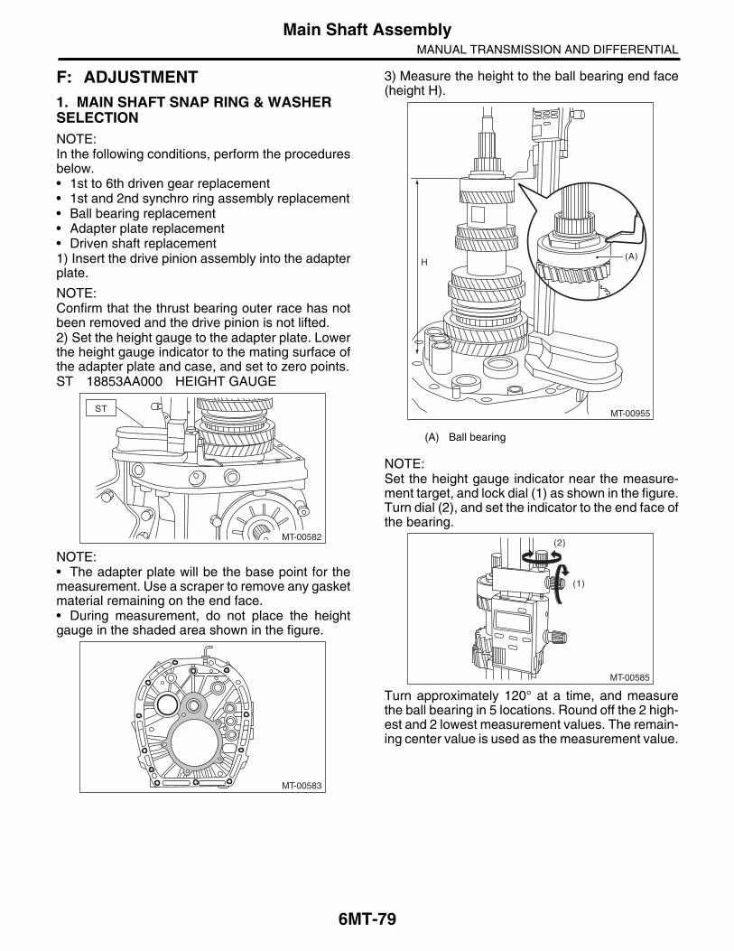
6MT-79
Main Shaft AssemblyMANUAL TRANSMISSION AND DIFFERENTIAL
F: ADJUSTMENT1. MAIN SHAFT SNAP RING & WASHER SELECTIONNOTE:In the following conditions, perform the proceduresbelow.• 1st to 6th driven gear replacement• 1st and 2nd synchro ring assembly replacement• Ball bearing replacement• Adapter plate replacement• Driven shaft replacement1) Insert the drive pinion assembly into the adapterplate.
NOTE:Confirm that the thrust bearing outer race has notbeen removed and the drive pinion is not lifted.2) Set the height gauge to the adapter plate. Lowerthe height gauge indicator to the mating surface ofthe adapter plate and case, and set to zero points.ST 18853AA000 HEIGHT GAUGE
NOTE:• The adapter plate will be the base point for themeasurement. Use a scraper to remove any gasketmaterial remaining on the end face.• During measurement, do not place the heightgauge in the shaded area shown in the figure.
3) Measure the height to the ball bearing end face(height H).
NOTE:Set the height gauge indicator near the measure-ment target, and lock dial (1) as shown in the figure.Turn dial (2), and set the indicator to the end face ofthe bearing.
Turn approximately 120° at a time, and measurethe ball bearing in 5 locations. Round off the 2 high-est and 2 lowest measurement values. The remain-ing center value is used as the measurement value.
MT-00582
ST
MT-00583
(A) Ball bearing
(A)
MT-00955
H
MT-00585
(2)
(1)

6MT-80
Main Shaft AssemblyMANUAL TRANSMISSION AND DIFFERENTIAL
4) According to the measurement value, select thesnap ring and washer from the following table.Snap ring
Washer
H: mm (in) Part No.Thickness: mm
(in)
270.83 — 271.40(10.66 — 10.69)
8050720101.65
(0.065)
271.41 — 271.98(10.69 — 10.71)
8050720111.95
(0.077)
271.99 — 272.56(10.71 — 10.73)
8050720122.25
(0.089)
H: mm (in) Part No.Thickness: mm
(in)
270.83 — 271.40(10.66 — 10.69)
8030670121.6
(0.063)
271.41 — 271.98(10.69 — 10.71)
8030670111.3
(0.051)
271.99 — 272.56(10.71 — 10.73)
8030670101.0
(0.039)
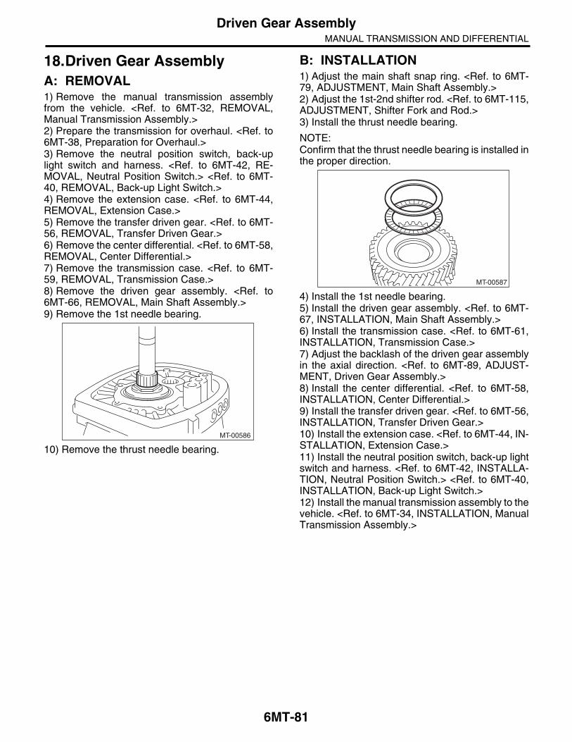
6MT-81
Driven Gear AssemblyMANUAL TRANSMISSION AND DIFFERENTIAL
18.Driven Gear AssemblyA: REMOVAL1) Remove the manual transmission assemblyfrom the vehicle. <Ref. to 6MT-32, REMOVAL,Manual Transmission Assembly.>2) Prepare the transmission for overhaul. <Ref. to6MT-38, Preparation for Overhaul.>3) Remove the neutral position switch, back-uplight switch and harness. <Ref. to 6MT-42, RE-MOVAL, Neutral Position Switch.> <Ref. to 6MT-40, REMOVAL, Back-up Light Switch.>4) Remove the extension case. <Ref. to 6MT-44,REMOVAL, Extension Case.>5) Remove the transfer driven gear. <Ref. to 6MT-56, REMOVAL, Transfer Driven Gear.>6) Remove the center differential. <Ref. to 6MT-58,REMOVAL, Center Differential.>7) Remove the transmission case. <Ref. to 6MT-59, REMOVAL, Transmission Case.>8) Remove the driven gear assembly. <Ref. to6MT-66, REMOVAL, Main Shaft Assembly.>9) Remove the 1st needle bearing.
10) Remove the thrust needle bearing.
B: INSTALLATION1) Adjust the main shaft snap ring. <Ref. to 6MT-79, ADJUSTMENT, Main Shaft Assembly.>2) Adjust the 1st-2nd shifter rod. <Ref. to 6MT-115,ADJUSTMENT, Shifter Fork and Rod.>3) Install the thrust needle bearing.
NOTE:Confirm that the thrust needle bearing is installed inthe proper direction.
4) Install the 1st needle bearing.5) Install the driven gear assembly. <Ref. to 6MT-67, INSTALLATION, Main Shaft Assembly.>6) Install the transmission case. <Ref. to 6MT-61,INSTALLATION, Transmission Case.>7) Adjust the backlash of the driven gear assemblyin the axial direction. <Ref. to 6MT-89, ADJUST-MENT, Driven Gear Assembly.>8) Install the center differential. <Ref. to 6MT-58,INSTALLATION, Center Differential.>9) Install the transfer driven gear. <Ref. to 6MT-56,INSTALLATION, Transfer Driven Gear.>10) Install the extension case. <Ref. to 6MT-44, IN-STALLATION, Extension Case.>11) Install the neutral position switch, back-up lightswitch and harness. <Ref. to 6MT-42, INSTALLA-TION, Neutral Position Switch.> <Ref. to 6MT-40,INSTALLATION, Back-up Light Switch.>12) Install the manual transmission assembly to thevehicle. <Ref. to 6MT-34, INSTALLATION, ManualTransmission Assembly.>
MT-00586
MT-00587
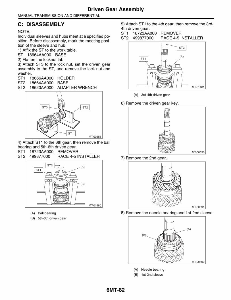
6MT-82
Driven Gear AssemblyMANUAL TRANSMISSION AND DIFFERENTIAL
C: DISASSEMBLYNOTE:Individual sleeves and hubs meet at a specified po-sition. Before disassembly, mark the meeting posi-tion of the sleeve and hub.1) Affix the ST to the work table.ST 18664AA000 BASE2) Flatten the locknut tab.3) Attach ST3 to the lock nut, set the driven gearassembly to the ST, and remove the lock nut andwasher.ST1 18666AA000 HOLDERST2 18664AA000 BASEST3 18620AA000 ADAPTER WRENCH
4) Attach ST1 to the 6th gear, then remove the ballbearing and 5th-6th driven gear.ST1 18723AA000 REMOVERST2 499877000 RACE 4-5 INSTALLER
5) Attach ST1 to the 4th gear, then remove the 3rd-4th driven gear.ST1 18723AA000 REMOVERST2 499877000 RACE 4-5 INSTALLER
6) Remove the driven gear key.
7) Remove the 2nd gear.
8) Remove the needle bearing and 1st-2nd sleeve.(A) Ball bearing
(B) 5th-6th driven gear
MT-00588
ST3 ST2
ST1
MT-01480
(A)
(B)
ST2
ST1
(A) 3rd-4th driven gear
(A) Needle bearing
(B) 1st-2nd sleeve
MT-01481
(A)
ST2
ST1
MT-00590
MT-00591
MT-00592
(A)
(B)

6MT-83
Driven Gear AssemblyMANUAL TRANSMISSION AND DIFFERENTIAL
9) Remove the outer baulk ring, 2nd synchro coneand inner baulk ring.
10) Using the ST, remove individual parts.ST 18754AA000 REMOVER
D: ASSEMBLYNOTE:When replacing the following parts, replace as aset.• Sleeve and hub• Outer baulk ring, 1st synchro cone and innerbaulk ring• Outer baulk ring, 2nd synchro cone and innerbaulk ring1) Apply adequate transmission gear oil to the mainshaft, 1st needle bearing and 1st drive gear innersurface.2) Install the 1st needle bearing.
3) Attach the 1st driven gear to the driven shaft.
4) Install the inner baulk ring.
(A) Outer baulk ring
(B) 2nd synchro cone
(C) Inner baulk ring
(A) 2nd bushing
(B) 1st-2nd hub
(C) Outer baulk ring
(D) 1st synchro cone
(E) Inner baulk ring
(F) 1st driven gear
(G) 1st needle bearing
MT-01502
(B)
(A)
(C)
(A)
(E)
(B)
(C)
(D)
(F)
(G)
MT-01715
ST
STMT-00595
MT-01729
MT-01730

6MT-84
Driven Gear AssemblyMANUAL TRANSMISSION AND DIFFERENTIAL
5) Match the protrusion of the 1st synchro cone tothe hole of the 1st drive gear, then install.
6) Install the outer baulk ring.
7) Install the 1st-2nd hub.
NOTE:• Match the cut out of the 1st-2nd hub with the pro-trusion on the outer baulk ring, then install.• Make sure that the 1st-2nd hub is installed in thecorrect direction.
8) Using the ST, install the 1st-2nd hub and 2ndbush.ST 18654AA000 INSTALLER
CAUTION:Do not apply pressure in excess of 40 kN (4.0 ton, 4.4 US ton, 3.9 Imp ton).
MT-01505
MT-00599
(A) 1st-2nd hub
(B) Outer baulk ring
(C) 1st-2nd hub cut out section
(D) Protrusion of the outer baulk ring
(E) 1st driven gear
(A) 2nd bushing
(B) 1st-2nd hub
MT-01716
(E)
(D)
(C)
(A)
(B)
(E)
(A)
MT-00601
(B)
(A)
ST
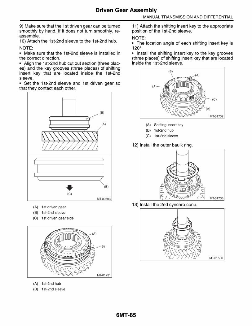
6MT-85
Driven Gear AssemblyMANUAL TRANSMISSION AND DIFFERENTIAL
9) Make sure that the 1st driven gear can be turnedsmoothly by hand. If it does not turn smoothly, re-assemble.10) Attach the 1st-2nd sleeve to the 1st-2nd hub.
NOTE:• Make sure that the 1st-2nd sleeve is installed inthe correct direction.• Align the 1st-2nd hub cut out section (three plac-es) and the key grooves (three places) of shiftinginsert key that are located inside the 1st-2ndsleeve.• Set the 1st-2nd sleeve and 1st driven gear sothat they contact each other.
11) Attach the shifting insert key to the appropriateposition of the 1st-2nd sleeve.
NOTE:• The location angle of each shifting insert key is120°.• Install the shifting insert key to the key grooves(three places) of shifting insert key that are locatedinside the 1st-2nd sleeve.
12) Install the outer baulk ring.
13) Install the 2nd synchro cone.(A) 1st driven gear
(B) 1st-2nd sleeve
(C) 1st driven gear side
(A) 1st-2nd hub
(B) 1st-2nd sleeve
MT-00603
(B)
(A)
(C)
(B)
MT-01731
(A)
(B)
(A) Shifting insert key
(B) 1st-2nd hub
(C) 1st-2nd sleeve
MT-01732
(A)(B)
(C)
(A)
(A)
MT-01733
MT-01506

6MT-86
Driven Gear AssemblyMANUAL TRANSMISSION AND DIFFERENTIAL
14) Install the inner baulk ring.
15) Apply adequate transmission gear oil to thebushing, 2nd needle bearing and 2nd drive gear in-ner surface.16) Install the 2nd needle bearing and 2nd drivengear.
NOTE:Match the protrusion of the 2nd synchro cone to thehole of the 2nd driven gear, then install.
17) Attach the key.
18) Using the ST, install the 3rd-4th driven gear.ST 18654AA000 INSTALLER
CAUTION:Do not apply pressure in excess of 40 kN (4.0 ton, 4.4 US ton, 3.9 Imp ton).
NOTE:• Make sure that the 3rd-4th driven gear is in-stalled in the correct direction.• Match the groove on the 3rd-4th driven gear tothe key.
19) Make sure that the 2nd driven gear can beturned smoothly by hand. If it does not turn smooth-ly, reassemble.20) Attach the key.
(A) 2nd needle bearing
(B) 2nd driven gear
(C) Protrusion of the 2nd synchro cone
MT-00606
MT-00607
(A)
(C)
(B)
MT-00608
(A) 4th gear
(B) 3rd gear
(C) 2nd gear
MT-00609
(A)
(C)
(B)
ST
MT-00610
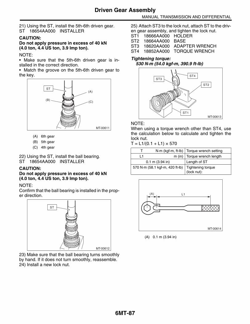
6MT-87
Driven Gear AssemblyMANUAL TRANSMISSION AND DIFFERENTIAL
21) Using the ST, install the 5th-6th driven gear.ST 18654AA000 INSTALLER
CAUTION:Do not apply pressure in excess of 40 kN (4.0 ton, 4.4 US ton, 3.9 Imp ton).
NOTE:• Make sure that the 5th-6th driven gear is in-stalled in the correct direction.• Match the groove on the 5th-6th driven gear tothe key.
22) Using the ST, install the ball bearing.ST 18654AA000 INSTALLER
CAUTION:Do not apply pressure in excess of 40 kN (4.0 ton, 4.4 US ton, 3.9 Imp ton).
NOTE:Confirm that the ball bearing is installed in the prop-er direction.
23) Make sure that the ball bearing turns smoothlyby hand. If it does not turn smoothly, reassemble.24) Install a new lock nut.
25) Attach ST3 to the lock nut, attach ST to the driv-en gear assembly, and tighten the lock nut.ST1 18666AA000 HOLDERST2 18664AA000 BASEST3 18620AA000 ADAPTER WRENCHST4 18852AA000 TORQUE WRENCH
Tightening torque:530 N·m (54.0 kgf-m, 390.9 ft-lb)
NOTE:When using a torque wrench other than ST4, usethe calculation below to calculate and tighten thelock nut.T = L1/(0.1 + L1) × 570
(A) 6th gear
(B) 5th gear
(C) 4th gear
MT-00611
(B)
ST(A)
(C)
MT-00612
ST
T N·m (kgf-m, ft-lb) Torque wrench setting
L1 m (in) Torque wrench length
0.1 m (3.94 in) Length of ST
570 N·m (58.1 kgf-m, 420 ft-lb) Tightening torque (lock nut):
(A) 0.1 m (3.94 in)
MT-00613ST1
ST2
ST4ST3
MT-00614
(A) L1
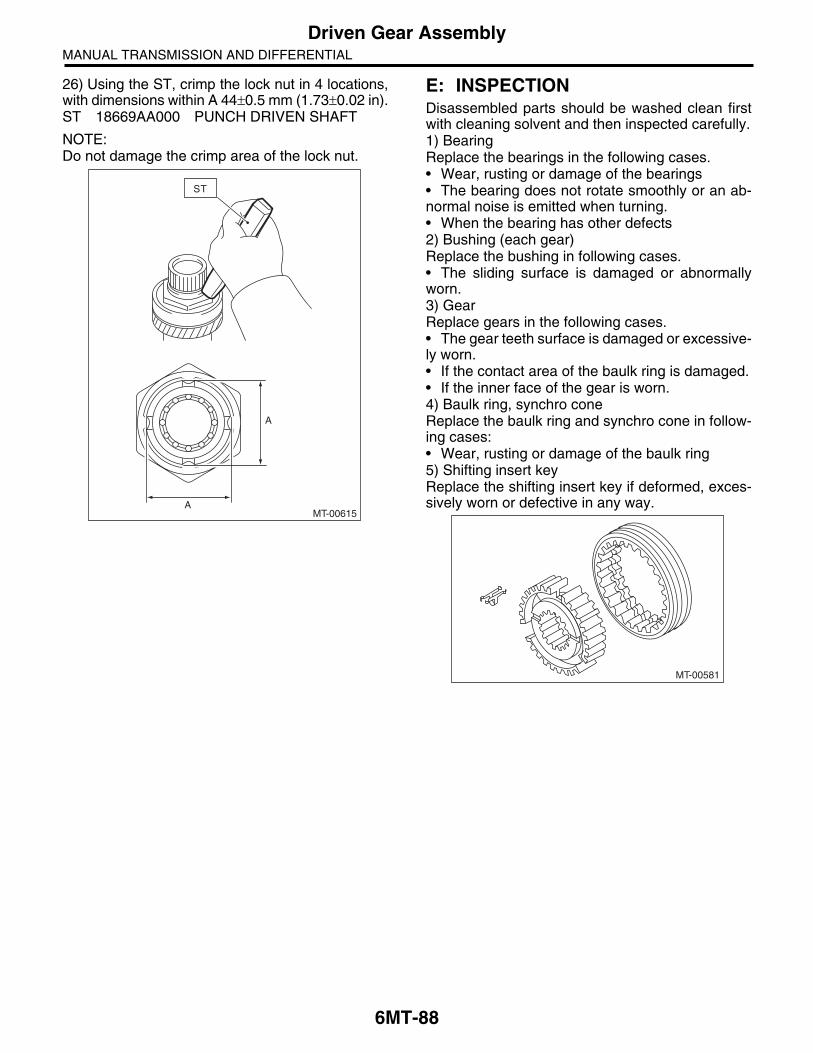
6MT-88
Driven Gear AssemblyMANUAL TRANSMISSION AND DIFFERENTIAL
26) Using the ST, crimp the lock nut in 4 locations,with dimensions within A 44 0.5 mm (1.73 0.02 in).ST 18669AA000 PUNCH DRIVEN SHAFT
NOTE:Do not damage the crimp area of the lock nut.
E: INSPECTIONDisassembled parts should be washed clean firstwith cleaning solvent and then inspected carefully.1) BearingReplace the bearings in the following cases.• Wear, rusting or damage of the bearings• The bearing does not rotate smoothly or an ab-normal noise is emitted when turning.• When the bearing has other defects2) Bushing (each gear)Replace the bushing in following cases.• The sliding surface is damaged or abnormallyworn.3) GearReplace gears in the following cases.• The gear teeth surface is damaged or excessive-ly worn.• If the contact area of the baulk ring is damaged.• If the inner face of the gear is worn.4) Baulk ring, synchro coneReplace the baulk ring and synchro cone in follow-ing cases:• Wear, rusting or damage of the baulk ring5) Shifting insert keyReplace the shifting insert key if deformed, exces-sively worn or defective in any way.
MT-00615
A
A
ST
MT-00581

6MT-89
Driven Gear AssemblyMANUAL TRANSMISSION AND DIFFERENTIAL
F: ADJUSTMENT1) Measure the length “H” from the transmissioncase and transfer bearing holder mating surface, tothe end face of the ball bearing.
2) Using the following calculation, calculate thethickness of the driven gear assembly washer.T = H – {5.8 0.05 mm (0.23 0.002 in)} – {0.1 — 0.3 mm (0.0039 — 0.0118 in)}
3) Select 0 to 3 washers from the following table,and adjust to the backlash that is closest to thestandard value.
Driven gear assembly axial direction backlash standard:
0.1 — 0.3 mm (0.0039 — 0.0118 in)
(A) Transmission case
(B) Ball bearing
(C) Driven gear ASSY
t Washer thickness
H Length from the transmission case and transfer bearing holder mating surface to the end face of the ball bearing
5.8 0.05 mm(0.23 0.002 in)
Collar thickness
0.1 — 0.3 mm(0.0039 — 0.0118 in)
Driven gear assembly axial direc-tion backlash standard
Washer
Part No. Thickness t mm (in)
803072030 0.15 (0.0059)
803072031 0.30 (0.0118)
803072032 0.45 (0.0177)
803072033 0.60 (0.0236)
MT-00616
(A)
H
(C)
(B)

6MT-90
Reverse Idler Gear AssemblyMANUAL TRANSMISSION AND DIFFERENTIAL
19.Reverse Idler Gear AssemblyA: REMOVAL1) Remove the manual transmission assemblyfrom the vehicle. <Ref. to 6MT-32, REMOVAL,Manual Transmission Assembly.>2) Prepare the transmission for overhaul. <Ref. to6MT-38, Preparation for Overhaul.>3) Remove the neutral position switch, back-uplight switch and harness. <Ref. to 6MT-42, RE-MOVAL, Neutral Position Switch.> <Ref. to 6MT-40, REMOVAL, Back-up Light Switch.>4) Remove the extension case. <Ref. to 6MT-44,REMOVAL, Extension Case.>5) Remove the transfer driven gear. <Ref. to 6MT-56, REMOVAL, Transfer Driven Gear.>6) Remove the center differential. <Ref. to 6MT-58,REMOVAL, Center Differential.>7) Remove the transmission case. <Ref. to 6MT-59, REMOVAL, Transmission Case.>8) Remove the reverse idler gear assembly. <Ref.to 6MT-66, REMOVAL, Main Shaft Assembly.>
B: INSTALLATION1) Select the reverse fork rod. <Ref. to 6MT-115,ADJUSTMENT, Shifter Fork and Rod.>2) Install the reverse idler gear assembly. <Ref. to6MT-67, INSTALLATION, Main Shaft Assembly.>3) Install the transmission case. <Ref. to 6MT-61,INSTALLATION, Transmission Case.>4) Install the center differential. <Ref. to 6MT-58,INSTALLATION, Center Differential.>5) Install the transfer driven gear. <Ref. to 6MT-56,INSTALLATION, Transfer Driven Gear.>6) Install the extension case. <Ref. to 6MT-44, IN-STALLATION, Extension Case.>7) Install the neutral position switch, back-up lightswitch and harness. <Ref. to 6MT-42, INSTALLA-TION, Neutral Position Switch.> <Ref. to 6MT-40,INSTALLATION, Back-up Light Switch.>8) Install the manual transmission assembly to thevehicle. <Ref. to 6MT-34, INSTALLATION, ManualTransmission Assembly.>
C: DISASSEMBLYNOTE:Sleeves and reverse gears meet at a specified po-sition. Before disassembly, mark the meeting posi-tion of the sleeve and hub.1) Remove the spring pin.
2) Remove the snap ring and washer.
3) Remove the counter high & low washer and re-verse idler gear.
(A) Counter high & low washer
(B) Reverse idler gear
MT-00617
MT-00618
MT-00619
(B)
(A)

6MT-91
Reverse Idler Gear AssemblyMANUAL TRANSMISSION AND DIFFERENTIAL
4) Remove the knock pin and reverse idler gearneedle bearing.
5) Remove the collar.6) Remove the reverse sleeve.
7) Remove the outer baulk ring, reverse synchrocone and inner baulk ring from the reverse sleeve.
8) Remove reverse idler gear No. 2.
9) Remove the counter high & low washer and nee-dle bearing.
10) Remove the knock pin.
11) Remove the snap ring and friction plate fromreverse gear.
(A) Knock pin
(B) Reverse idler gear needle bearing
(A) Reverse sleeve
(B) Outer baulk ring
(C) Reverse synchro cone
(D) Inner baulk ring
MT-00620
(A)
(B)
MT-00622
MT-01507
(A)
(B)(C)
(D)
(A) Needle bearing
(B) Counter high & low washer
(A) Snap ring
(B) Friction plate
MT-00624
MT-00625
(A)
(B)
MT-00626
MT-00627
(B)
(A)
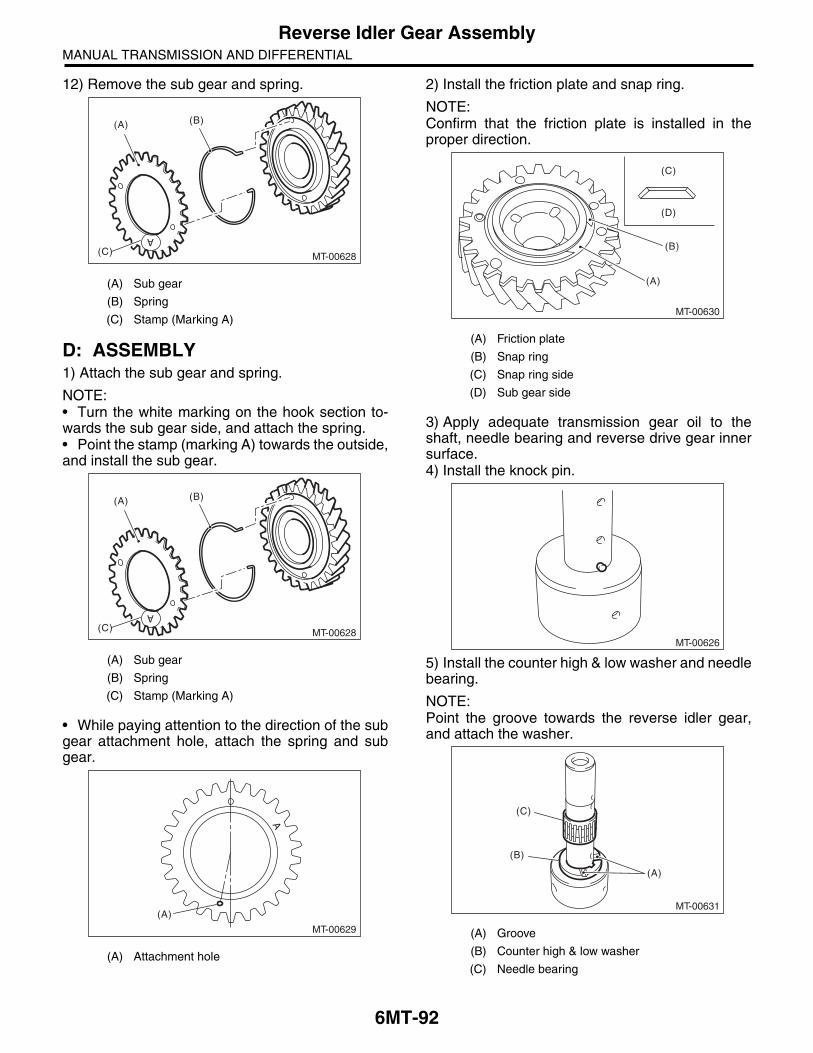
6MT-92
Reverse Idler Gear AssemblyMANUAL TRANSMISSION AND DIFFERENTIAL
12) Remove the sub gear and spring.
D: ASSEMBLY1) Attach the sub gear and spring.
NOTE:• Turn the white marking on the hook section to-wards the sub gear side, and attach the spring.• Point the stamp (marking A) towards the outside,and install the sub gear.
• While paying attention to the direction of the subgear attachment hole, attach the spring and subgear.
2) Install the friction plate and snap ring.
NOTE:Confirm that the friction plate is installed in theproper direction.
3) Apply adequate transmission gear oil to theshaft, needle bearing and reverse drive gear innersurface.4) Install the knock pin.
5) Install the counter high & low washer and needlebearing.
NOTE:Point the groove towards the reverse idler gear,and attach the washer.
(A) Sub gear
(B) Spring
(C) Stamp (Marking A)
(A) Sub gear
(B) Spring
(C) Stamp (Marking A)
(A) Attachment hole
MT-00628
(B)(A)
(C)
A
MT-00628
(B)(A)
(C)
A
MT-00629
(A)
A
(A) Friction plate
(B) Snap ring
(C) Snap ring side
(D) Sub gear side
(A) Groove
(B) Counter high & low washer
(C) Needle bearing
MT-00630
(C)
(D)
(A)
(B)
MT-00626
MT-00631
(C)
(B)
(A)

6MT-93
Reverse Idler Gear AssemblyMANUAL TRANSMISSION AND DIFFERENTIAL
6) Install the reverse idler gear No. 2.
7) Attach the shifting insert key to the appropriatelocation of the reverse sleeve.
NOTE:• The location angle of each shifting insert key is120°.• Refer to the following figure to install the shiftinginsert key.
8) Attach the reverse sleeve to the reverse idlergear No. 2.
NOTE:Confirm that the reverse sleeve is installed in theproper direction.
9) Apply adequate transmission gear oil to the col-lar, needle bearing and reverse drive gear innersurface.10) Install the outer baulk ring, reverse synchrocone and inner baulk ring.
11) Install the collar and needle bearing, then theknock pin.
(A) Reverse sleeve
(B) Shifting insert key
MT-00632
(B)(A)
(B)
(A)
MT-00633
(A) Outer baulk ring
(B) Reverse synchro cone
(C) Inner baulk ring
(A) Collar
(B) Needle bearing
(C) Knock pin
MT-00634
MT-00635
(A) (B)
(C)
MT-00636
(C)
(B)
(A)

6MT-94
Reverse Idler Gear AssemblyMANUAL TRANSMISSION AND DIFFERENTIAL
12) Match the protrusion of the reverse synchrocone to the hole on the reverse idler gear, and in-stall the reverse idler gear.
13) Point the groove towards the reverse idler gear,and attach the counter high & low washer and thewasher.14) Using the ST, install the snap ring.ST 18672AA000 GUIDE CLIP
15) Inspect and adjust the clearance between thesnap ring and the washer. <Ref. to 6MT-94, IN-SPECTION, Reverse Idler Gear Assembly.>16) Install a new spring pin.
E: INSPECTIONDisassembled parts should be washed clean firstwith cleaning solvent and then inspected carefully.1) BearingReplace the bearings in the following cases.• Wear, rusting or damage of the bearings• The bearing does not rotate smoothly or an ab-normal noise is emitted when turning.• When the bearing has other defects2) Bushing (each gear)Replace the bushing in following cases.• The sliding surface is damaged or abnormallyworn.
3) GearReplace gears in the following cases.• The gear teeth surface is damaged or excessive-ly worn.• If the contact area of the baulk ring is damaged.• If the inner face of the gear is worn.4) Baulk ring, synchro coneReplace the baulk ring and synchro cone in follow-ing cases:• Wear, rusting or damage of the baulk ring5) Shifting insert keyReplace the shifting insert key if deformed, exces-sively worn or defective in any way.
6) Check clearance between the snap ring andwasher.
Clearance specification:0.1 — 0.3 mm (0.0039 — 0.0118 in)
If the clearance is out of the specification, select asnap ring from the following table and perform re-placement.
After replacing the snap ring, inspect the clearance.
(A) Protrusion on the reverse synchro cone
(B) Hole of the reverse idler gear
MT-01508
(A)
(B)
MT-00638
ST
Snap ring
Part No. Thickness mm (in)
031319000 1.50 (0.059)
805019030 1.60 (0.062)
805019010 1.72 (0.068)
MT-00581
MT-00639
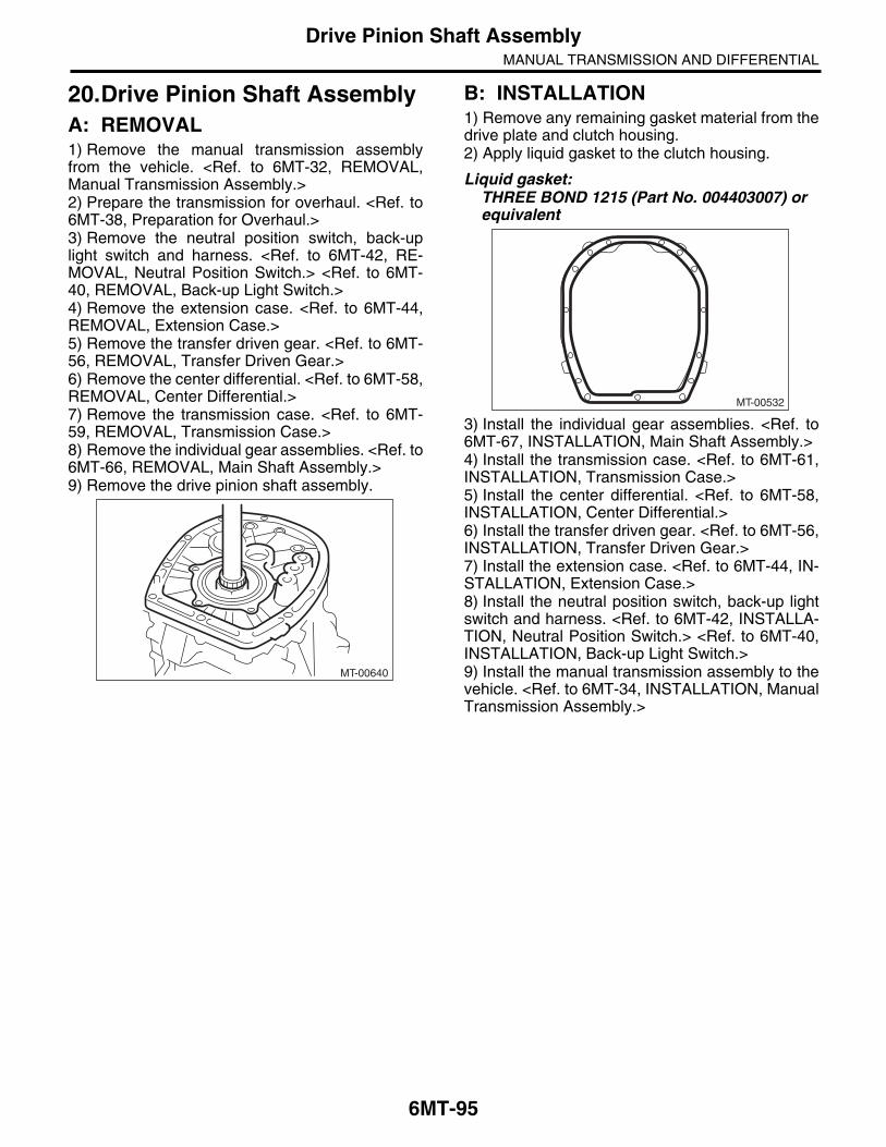
6MT-95
Drive Pinion Shaft AssemblyMANUAL TRANSMISSION AND DIFFERENTIAL
20.Drive Pinion Shaft AssemblyA: REMOVAL1) Remove the manual transmission assemblyfrom the vehicle. <Ref. to 6MT-32, REMOVAL,Manual Transmission Assembly.>2) Prepare the transmission for overhaul. <Ref. to6MT-38, Preparation for Overhaul.>3) Remove the neutral position switch, back-uplight switch and harness. <Ref. to 6MT-42, RE-MOVAL, Neutral Position Switch.> <Ref. to 6MT-40, REMOVAL, Back-up Light Switch.>4) Remove the extension case. <Ref. to 6MT-44,REMOVAL, Extension Case.>5) Remove the transfer driven gear. <Ref. to 6MT-56, REMOVAL, Transfer Driven Gear.>6) Remove the center differential. <Ref. to 6MT-58,REMOVAL, Center Differential.>7) Remove the transmission case. <Ref. to 6MT-59, REMOVAL, Transmission Case.>8) Remove the individual gear assemblies. <Ref. to6MT-66, REMOVAL, Main Shaft Assembly.>9) Remove the drive pinion shaft assembly.
B: INSTALLATION1) Remove any remaining gasket material from thedrive plate and clutch housing.2) Apply liquid gasket to the clutch housing.
Liquid gasket:THREE BOND 1215 (Part No. 004403007) or equivalent
3) Install the individual gear assemblies. <Ref. to6MT-67, INSTALLATION, Main Shaft Assembly.>4) Install the transmission case. <Ref. to 6MT-61,INSTALLATION, Transmission Case.>5) Install the center differential. <Ref. to 6MT-58,INSTALLATION, Center Differential.>6) Install the transfer driven gear. <Ref. to 6MT-56,INSTALLATION, Transfer Driven Gear.>7) Install the extension case. <Ref. to 6MT-44, IN-STALLATION, Extension Case.>8) Install the neutral position switch, back-up lightswitch and harness. <Ref. to 6MT-42, INSTALLA-TION, Neutral Position Switch.> <Ref. to 6MT-40,INSTALLATION, Back-up Light Switch.>9) Install the manual transmission assembly to thevehicle. <Ref. to 6MT-34, INSTALLATION, ManualTransmission Assembly.>
MT-00640
MT-00532

6MT-96
Drive Pinion Shaft AssemblyMANUAL TRANSMISSION AND DIFFERENTIAL
C: DISASSEMBLYNOTE:Replace the drive pinion shaft and the hypoid driv-en gear as a set.1) Remove the oil guide A.
2) Remove the drive pinion shaft and shim from theadapter plate.
3) Affix the ST to the work table.ST 18664AA000 BASE4) Flatten the locknut tab.5) Attach ST3 to the locknut, and set the drive pin-ion shaft to the ST. Remove the lock nut and wash-er.ST1 18667AA000 HOLDERST2 18664AA000 BASEST3 18621AA000 ADAPTER WRENCH
6) Using the ST, remove the taper roller bearing as-sembly.ST 18723AA000 REMOVER
(A) Oil guide A
MT-01624
(A)
MT-00642
MT-00643
ST2ST3
ST1
MT-00644
ST

6MT-97
Drive Pinion Shaft AssemblyMANUAL TRANSMISSION AND DIFFERENTIAL
D: ASSEMBLY1) Using the ST, measure drive pinion measure-ment “A”.
NOTE:When selecting the drive pinion shim, refer to mea-surement “A”.ST 398643600 GAUGE
2) Using the ST and a press, attach the inner bear-ing of the taper roller bearing to the drive pinionshaft.ST 18723AA000 REMOVER
CAUTION:Do not apply pressure in excess of 40 kN (4.0 ton, 4.4 US ton, 3.9 Imp ton).
3) Using the ST and a press, attach the outer raceand the taper roller bearing to the drive pinion shaft.ST 18723AA000 REMOVER
NOTE:Push in to a position where the bearing rotatessmoothly.
4) Attach the washer and a new lock nut.5) Set the ST to the drive pinion, and tighten thelock nut.ST1 18667AA000 HOLDERST2 18664AA000 BASEST3 18621AA000 ADAPTER WRENCHST4 18852AA000 TORQUE WRENCH
NOTE:Tighten using the ST and the straight line torquewrench.
Tightening torque:265 N·m (27.0 kgf-m, 195.4 ft-lb)
NOTE:When using a torque wrench other than ST4, usethe calculation below to calculate and tighten thelock nut.Tighten using the ST and the straight line torquewrench.T = L1/(0.1 + L1) × 285
6) Measure the starting torque. <Ref. to 6MT-99,INSPECTION, Drive Pinion Shaft Assembly.>
(A) Outer race
MT-00645A
ST
MT-00646
ST
MT-00647
(A)
ST
T N·m (kgf-m, ft-lb) Torque wrench setting
L1 m (in) Torque wrench length
0.1 m (3.94 in) Length of ST
285 N·m (29.0 kgf-m, 210 ft-lb) Tightening torque (lock nut):
(A) 0.1 m (3.94 in)
MT-00648
ST2
ST4ST3
ST1
MT-00614
(A) L1
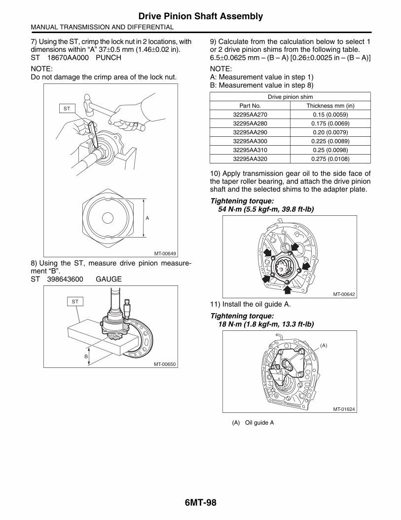
6MT-98
Drive Pinion Shaft AssemblyMANUAL TRANSMISSION AND DIFFERENTIAL
7) Using the ST, crimp the lock nut in 2 locations, withdimensions within “A” 37 0.5 mm (1.46 0.02 in).ST 18670AA000 PUNCH
NOTE:Do not damage the crimp area of the lock nut.
8) Using the ST, measure drive pinion measure-ment “B”.ST 398643600 GAUGE
9) Calculate from the calculation below to select 1or 2 drive pinion shims from the following table.6.5 0.0625 mm – (B – A) [0.26 0.0025 in – (B – A)]
NOTE:A: Measurement value in step 1)B: Measurement value in step 8)
10) Apply transmission gear oil to the side face ofthe taper roller bearing, and attach the drive pinionshaft and the selected shims to the adapter plate.
Tightening torque:54 N·m (5.5 kgf-m, 39.8 ft-lb)
11) Install the oil guide A.
Tightening torque:18 N·m (1.8 kgf-m, 13.3 ft-lb)
MT-00649
A
ST
MT-00650
B
ST
Drive pinion shim
Part No. Thickness mm (in)
32295AA270 0.15 (0.0059)
32295AA280 0.175 (0.0069)
32295AA290 0.20 (0.0079)
32295AA300 0.225 (0.0089)
32295AA310 0.25 (0.0098)
32295AA320 0.275 (0.0108)
(A) Oil guide A
MT-00642
MT-01624
(A)
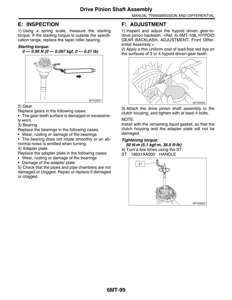
6MT-99
Drive Pinion Shaft AssemblyMANUAL TRANSMISSION AND DIFFERENTIAL
E: INSPECTION1) Using a spring scale, measure the startingtorque. If the starting torque is outside the specifi-cation range, replace the taper roller bearing.
Starting torque:0 — 0.95 N (0 — 0.097 kgf, 0 — 0.21 lb)
2) GearReplace gears in the following cases.• The gear teeth surface is damaged or excessive-ly worn.3) BearingReplace the bearings in the following cases.• Wear, rusting or damage of the bearings• The bearing does not rotate smoothly or an ab-normal noise is emitted when turning.4) Adapter plateReplace the adapter plate in the following cases:• Wear, rusting or damage of the bearings• Damage of the adapter plate5) Check that the pipes and pipe chambers are notdamaged or clogged. Repair or replace if damagedor clogged.
F: ADJUSTMENT1) Inspect and adjust the hypoid driven gear-to-drive pinion backlash. <Ref. to 6MT-108, HYPOIDGEAR BACKLASH, ADJUSTMENT, Front Differ-ential Assembly.>2) Apply a thin uniform coat of lead-free red dye onthe surfaces of 3 or 4 hypoid driven gear teeth.
3) Attach the drive pinion shaft assembly to theclutch housing, and tighten with at least 4 bolts.
NOTE:Install with the remaining liquid gasket, so that theclutch housing and the adapter plate will not bedamaged.
Tightening torque:50 N·m (5.1 kgf-m, 36.9 ft-lb)
4) Turn a few times using the ST.ST 18631AA000 HANDLE
MT-00651MT-00652
MT-00653
ST

6MT-100
Drive Pinion Shaft AssemblyMANUAL TRANSMISSION AND DIFFERENTIAL
5) Remove the drive pinion shaft assembly, and in-spect the mating condition of the teeth. If the mat-ing condition of the teeth is not correct, changeshim thickness to adjust backlash.• Correct tooth contactCheck item: Tooth contact surface is slightlyshifted toward the toe side under a no-load con-dition. (When driving, it moves towards the heelside.)
• Face contactCheck item: Backlash is too large.Contact pattern
Corrective action: Reconfirm and adjust backlash.
• Flank contactCheck item: Backlash is too small.Contact pattern
Corrective action: Reconfirm and adjust backlash.
• Toe contact (inside contact)Check item: Teeth contact area is too small.Contact pattern
Corrective action: Reduce the thickness of thedrive pinion shim according to the procedure formoving the drive pinion away from the driven gear.
(A) Toe side
(B) Heel side
(A)
(B)
MT-01401
AT-00208
AT-01253
AT-00209
AT-01254
AT-00210
AT-00213

6MT-101
Drive Pinion Shaft AssemblyMANUAL TRANSMISSION AND DIFFERENTIAL
• Heel contact (outside end contact)Check item: Teeth contact area is too small.Contact pattern
Corrective action: Increase thickness of the drivepinion shim according to the procedures for movingthe drive pinion closer to the driven gear.
AT-00211
AT-00212
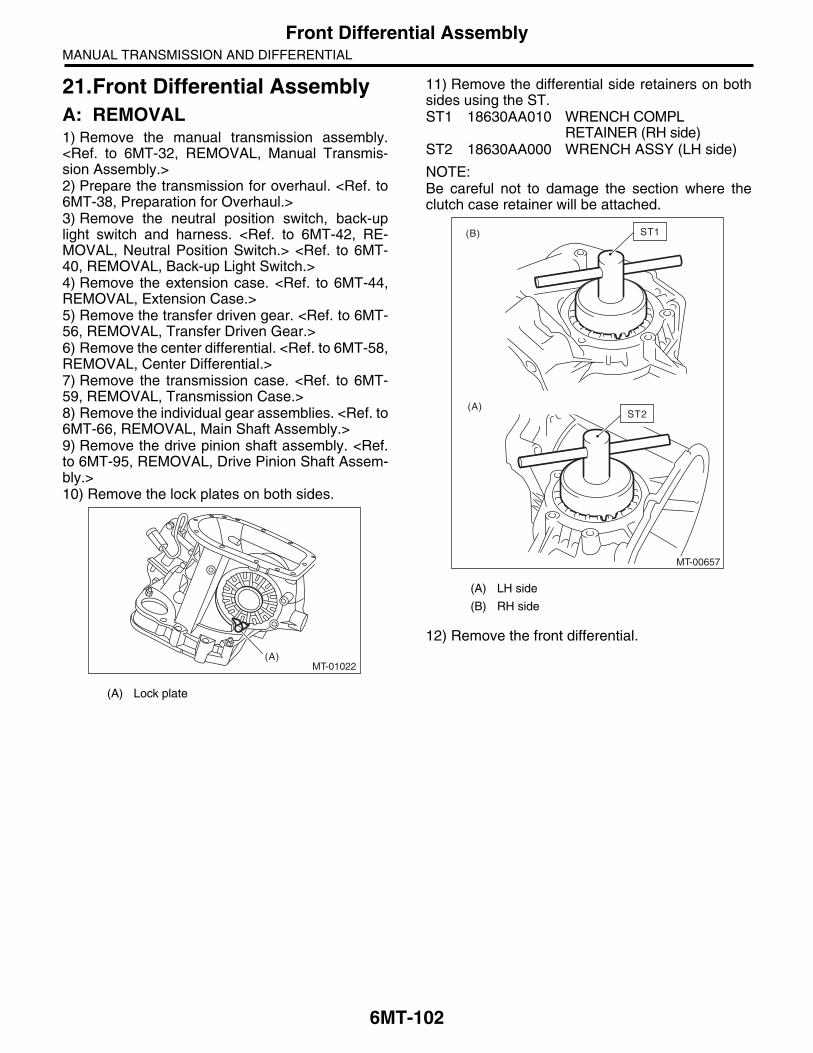
6MT-102
Front Differential AssemblyMANUAL TRANSMISSION AND DIFFERENTIAL
21.Front Differential AssemblyA: REMOVAL1) Remove the manual transmission assembly.<Ref. to 6MT-32, REMOVAL, Manual Transmis-sion Assembly.>2) Prepare the transmission for overhaul. <Ref. to6MT-38, Preparation for Overhaul.>3) Remove the neutral position switch, back-uplight switch and harness. <Ref. to 6MT-42, RE-MOVAL, Neutral Position Switch.> <Ref. to 6MT-40, REMOVAL, Back-up Light Switch.>4) Remove the extension case. <Ref. to 6MT-44,REMOVAL, Extension Case.>5) Remove the transfer driven gear. <Ref. to 6MT-56, REMOVAL, Transfer Driven Gear.>6) Remove the center differential. <Ref. to 6MT-58,REMOVAL, Center Differential.>7) Remove the transmission case. <Ref. to 6MT-59, REMOVAL, Transmission Case.>8) Remove the individual gear assemblies. <Ref. to6MT-66, REMOVAL, Main Shaft Assembly.>9) Remove the drive pinion shaft assembly. <Ref.to 6MT-95, REMOVAL, Drive Pinion Shaft Assem-bly.>10) Remove the lock plates on both sides.
11) Remove the differential side retainers on bothsides using the ST.ST1 18630AA010 WRENCH COMPL
RETAINER (RH side)ST2 18630AA000 WRENCH ASSY (LH side)
NOTE:Be careful not to damage the section where theclutch case retainer will be attached.
12) Remove the front differential.
(A) Lock plate
MT-01022(A)
(A) LH side
(B) RH side
(A)
(B)
MT-00657
ST1
ST2

6MT-103
Front Differential AssemblyMANUAL TRANSMISSION AND DIFFERENTIAL
B: INSTALLATION1) Install the differential assembly to the clutchhousing.2) Apply oil to the screw threads of the side retain-er.3) Remove the O-rings on both sides of the side re-tainer.4) Install the differential side retainers to bothsides, using the ST.ST1 18630AA010 WRENCH COMPL
RETAINER (RH side)ST2 18630AA000 WRENCH ASSY (LH side)
NOTE:Be careful not to damage the oil seal.
5) Inspect and adjust the hypoid gear backlash.<Ref. to 6MT-107, HYPOID GEAR BACKLASH,INSPECTION, Front Differential Assembly.>6) Inspect and adjust the tooth contact. <Ref. to6MT-99, ADJUSTMENT, Drive Pinion Shaft As-sembly.>
7) Mark the mating positions of the left and rightside retainers and the clutch housing.
8) Remove the differential side retainers from bothsides.
NOTE:When removing the side retainer, record how manytimes it was turned to remove.9) Install new O-rings to the side retainers on bothsides.10) Attach the differential side retainers to bothsides.
NOTE:When attaching, turn the side retainer the samenumber of turns it took to remove, and align themarks.11) Install the lock plate.
Tightening torque:25 N·m (2.5 kgf-m, 18.4 ft-lb)
NOTE:Be careful not to confuse the left and right side lockplates.
12) Remove any remaining liquid gasket from theclutch housing and adapter plate.
(A) LH side
(B) RH side
(A)
(B)
MT-00657
ST1
ST2
(A) LH
(B) RH
MT-00658
MT-00659
(A) (B)

6MT-104
Front Differential AssemblyMANUAL TRANSMISSION AND DIFFERENTIAL
13) Apply liquid gasket to the clutch housing.
Liquid gasket:THREE BOND 1215 (Part No. 004403007) or equivalent
14) Install the drive pinion shaft assembly. <Ref. to6MT-95, INSTALLATION, Drive Pinion Shaft As-sembly.>15) Install the individual gear assemblies all atonce. <Ref. to 6MT-67, INSTALLATION, MainShaft Assembly.>16) Install the transmission case. <Ref. to 6MT-61,INSTALLATION, Transmission Case.>17) Install the center differential. <Ref. to 6MT-58,INSTALLATION, Center Differential.>18) Install the transfer driven gear. <Ref. to 6MT-56, INSTALLATION, Transfer Driven Gear.>19) Install the extension case. <Ref. to 6MT-44, IN-STALLATION, Extension Case.>20) Install the neutral position switch, back-up lightswitch and harness. <Ref. to 6MT-42, INSTALLA-TION, Neutral Position Switch.> <Ref. to 6MT-40,INSTALLATION, Back-up Light Switch.>21) Install the manual transmission assembly to thevehicle. <Ref. to 6MT-34, INSTALLATION, ManualTransmission Assembly.>
C: DISASSEMBLY1. DIFFERENTIAL CASE1) Fix the differential assembly on a vice, and re-move the hypoid driven gear.ST 18270KA020 SOCKET (E20)
2) Remove the side bearing of the hypoid drivengear using the ST.ST 399527700 PULLER SET
3) Using the ST, remove the roller bearing.ST 498077000 REMOVER
MT-00532
MT-00660
MT-00663
ST
MT-00665
ST

6MT-105
Front Differential AssemblyMANUAL TRANSMISSION AND DIFFERENTIAL
2. SIDE RETAINER1) Remove the O-ring.
2) Remove the oil seal.
3) Remove the claw of ST1, and attach the claw ofST2.ST1 398527700 PULLER ASSYST2 18760AA000 CLAW
4) Remove the bearing outer race from the side re-tainer, using the ST.ST1 398527700 PULLER ASSYST2 18760AA000 CLAW
(A) Claw
MT-00666
MT-01454
MT-00668
(A)
ST2
ST1
(A) Side retainer
MT-00669
(A)
ST2
ST1

6MT-106
Front Differential AssemblyMANUAL TRANSMISSION AND DIFFERENTIAL
D: ASSEMBLY1. DIFFERENTIAL CASE1) Use the ST to attach the RH and LH bearing in-ner races to the differential case.ST1 398437700 INSTALLERST2 398497701 SEAT
CAUTION:Do not apply pressure in excess of 20 kN (2.0 ton, 2.2 US ton, 2.0 Imp ton).
NOTE:Always replace inner races and outer races as aset.
2) Attach the hypoid driven gear to the differentialcase.ST 18270KA020 SOCKET (E20)
Tightening torque:69 N·m (7.0 kgf-m, 50.9 ft-lb)
2. SIDE RETAINERNOTE:Install the oil seal and O-ring of side retainer afterthe adjustment of backlash and tooth contact.1) Install the bearing outer race to side retainer.2) Using the ST, install the oil seal.ST 18675AA000 DIFFERENTIAL SIDE OIL
SEAL INSTALLER
NOTE:• Use a new oil seal.• Apply oil to the oil seal lips.
3) Install the O-ring.
NOTE:Use new O-rings.
MT-00670
ST1
ST2
MT-00660
AT-00226
ST
AT-00219
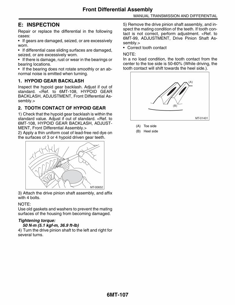
6MT-107
Front Differential AssemblyMANUAL TRANSMISSION AND DIFFERENTIAL
E: INSPECTIONRepair or replace the differential in the followingcases:• If gears are damaged, seized, or are excessivelyworn.• If differential case sliding surfaces are damaged,seized, or are excessively worn.• If there is damage, rust or wear in the bearings orbearing locations.• If the bearing does not rotate smoothly or an ab-normal noise is emitted when turning.
1. HYPOID GEAR BACKLASHInspect the hypoid gear backlash. Adjust if out ofstandard. <Ref. to 6MT-108, HYPOID GEARBACKLASH, ADJUSTMENT, Front Differential As-sembly.>
2. TOOTH CONTACT OF HYPOID GEAR1) Check that the hypoid gear backlash is within thestandard value. Adjust if out of standard. <Ref. to6MT-108, HYPOID GEAR BACKLASH, ADJUST-MENT, Front Differential Assembly.>2) Apply a thin uniform coat of lead-free red dye onthe surfaces of 3 or 4 hypoid driven gear teeth.
3) Attach the drive pinion shaft assembly, and affixwith 4 bolts.
NOTE:Use old gaskets and washers to prevent the matingsurfaces of the housing from becoming damaged.
Tightening torque:50 N·m (5.1 kgf-m, 36.9 ft-lb)
4) Turn the drive pinion shaft to the left and right forseveral turns.
5) Remove the drive pinion shaft assembly, and in-spect the mating condition of the teeth. If tooth con-tact is not correct, perform adjustment. <Ref. to6MT-99, ADJUSTMENT, Drive Pinion Shaft As-sembly.>• Correct tooth contact
NOTE:In a no load condition, the tooth contact from thecenter to the toe side is 50-60% (While driving, thetooth contact will shift towards the heel side.).
MT-00652
(A) Toe side
(B) Heel side
(A)
(B)
MT-01401

6MT-108
Front Differential AssemblyMANUAL TRANSMISSION AND DIFFERENTIAL
F: ADJUSTMENT1. HYPOID GEAR BACKLASH1) Attach the RH and LH side retainers.ST1 18630AA010 WRENCH COMPL
RETAINER (RH side)ST2 18630AA000 WRENCH ASSY (LH side)
NOTE:• Screw in the RH side side retainer a little furtherthan the LH side.• WRENCH ASSY (499787000) can also be used.2) Attach the drive pinion shaft assembly, and affixwith 5 bolts.
NOTE:Use old gaskets and washers to prevent the matingsurfaces of the housing from becoming damaged.
Tightening torque:50 N·m (5.1 kgf-m, 36.9 ft-lb)
3) Using the ST, loosen the differential side retainerRH, and screw in the differential side retainer LHuntil the hypoid driven gear just contacts the drivepinion.ST1 18630AA010 WRENCH COMPL
RETAINER (RH side)ST2 18630AA000 WRENCH ASSY (LH side)4) Use the ST to turn the drive pinion shaft a fewtimes.ST 18631AA000 HANDLE
5) Repeat steps 3) and 4) until differential side re-tainer LH does not turn anymore. For differentialside retainer RH, screw in until the inner race andouter race just comes into contact. This is the “ze-ro” backlash state.
6) Mark the mating positions of the left and rightside retainers and the clutch housing.
7) Turn the back differential side retainer LH by 3 notches, and screw in the differential side retainerRH by 3 notches.8) Temporarily attach the LH side retainer lockplate.9) Turn the differential side retainer RH by 1.25 notches.10) Temporarily attach the RH side retainer lockplate.
NOTE:• If the lock plate cannot be aligned, adjust the po-sition toward the tightened side.• The notch on the lock plate moves by 0.5 notch ifthe lock plate is turned upside down when installed.11) Use the ST to fix the drive pinion shaft in place.ST 18621AA000 ADAPTER WRENCH
12) Install the SUBARU genuine axle shaft to thefront differential left and right sides.Part No. 38415AA000 AXLE SHAFT
MT-00653
ST
MT-00658
ST
MT-00674
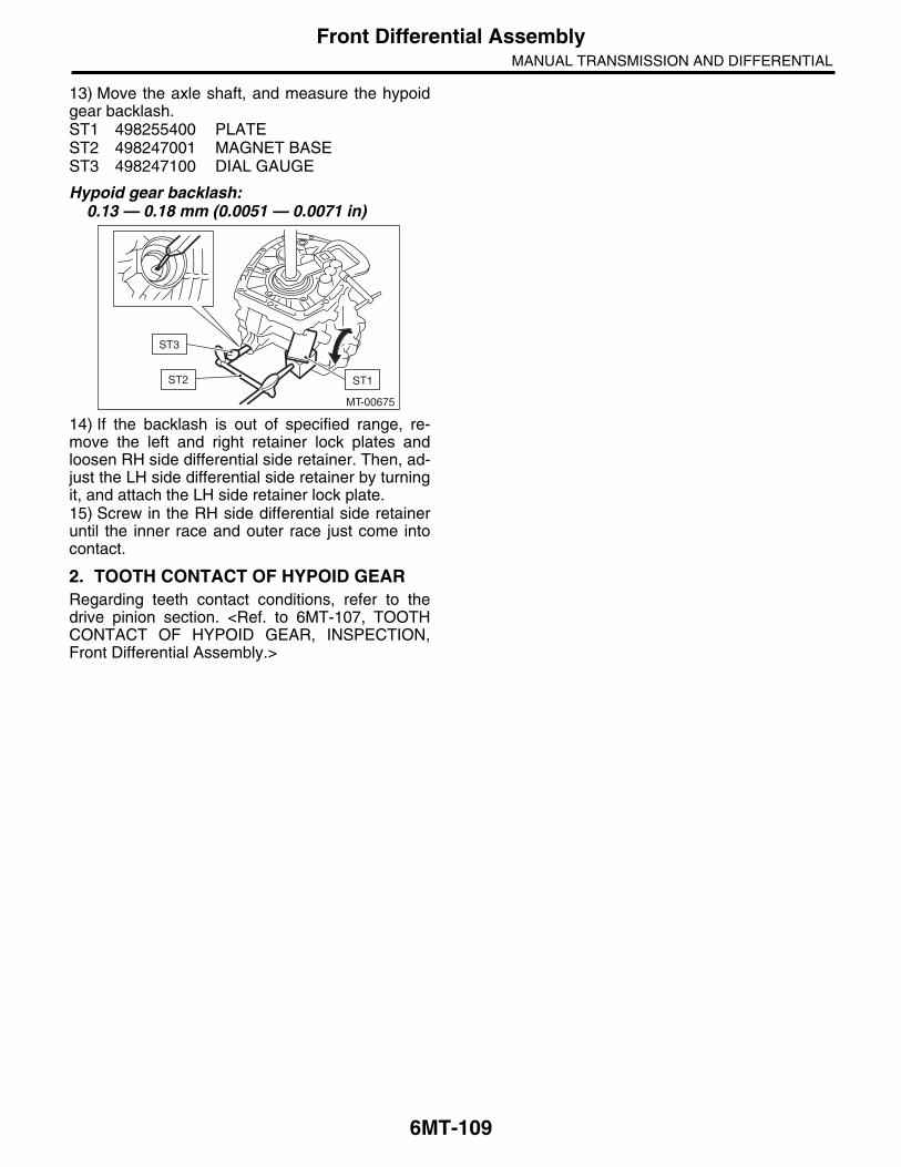
6MT-109
Front Differential AssemblyMANUAL TRANSMISSION AND DIFFERENTIAL
13) Move the axle shaft, and measure the hypoidgear backlash.ST1 498255400 PLATEST2 498247001 MAGNET BASEST3 498247100 DIAL GAUGE
Hypoid gear backlash:0.13 — 0.18 mm (0.0051 — 0.0071 in)
14) If the backlash is out of specified range, re-move the left and right retainer lock plates andloosen RH side differential side retainer. Then, ad-just the LH side differential side retainer by turningit, and attach the LH side retainer lock plate.15) Screw in the RH side differential side retaineruntil the inner race and outer race just come intocontact.
2. TOOTH CONTACT OF HYPOID GEARRegarding teeth contact conditions, refer to thedrive pinion section. <Ref. to 6MT-107, TOOTHCONTACT OF HYPOID GEAR, INSPECTION,Front Differential Assembly.>
MT-00675
ST2 ST1
ST3

6MT-110
Shifter Fork and RodMANUAL TRANSMISSION AND DIFFERENTIAL
22.Shifter Fork and RodA: REMOVAL1) Remove the manual transmission assemblyfrom the vehicle. <Ref. to 6MT-32, REMOVAL,Manual Transmission Assembly.>2) Prepare the transmission for overhaul. <Ref. to6MT-38, Preparation for Overhaul.>3) Remove the neutral position switch, back-uplight switch and harness. <Ref. to 6MT-42, RE-MOVAL, Neutral Position Switch.> <Ref. to 6MT-40, REMOVAL, Back-up Light Switch.>4) Remove the extension case. <Ref. to 6MT-44,REMOVAL, Extension Case.>5) Remove the transfer driven gear. <Ref. to 6MT-56, REMOVAL, Transfer Driven Gear.>6) Remove the center differential. <Ref. to 6MT-58,REMOVAL, Center Differential.>7) Remove the transmission case. <Ref. to 6MT-59, REMOVAL, Transmission Case.>8) Remove the individual gear assemblies. <Ref. to6MT-66, REMOVAL, Main Shaft Assembly.>
B: INSTALLATION1) Install the individual gear assemblies all at once.<Ref. to 6MT-67, INSTALLATION, Main Shaft As-sembly.>2) Install the transmission case. <Ref. to 6MT-61,INSTALLATION, Transmission Case.>3) Install the center differential. <Ref. to 6MT-58,INSTALLATION, Center Differential.>4) Install the transfer driven gear. <Ref. to 6MT-56,INSTALLATION, Transfer Driven Gear.>5) Install the extension case. <Ref. to 6MT-44, IN-STALLATION, Extension Case.>6) Install the neutral position switch, back-up lightswitch and harness. <Ref. to 6MT-42, INSTALLA-TION, Neutral Position Switch.> <Ref. to 6MT-40,INSTALLATION, Back-up Light Switch.>7) Install the manual transmission assembly to thevehicle. <Ref. to 6MT-34, INSTALLATION, ManualTransmission Assembly.>
C: DISASSEMBLYNOTE:Discard the removed spring pin, and replace with anew part.
1. REVERSE SHIFTER FORK1) Remove the reverse fork using the ST.ST 398791700 REMOVER
2) Remove the reverse shifter arm using the ST.ST 398791700 REMOVER
MT-00680
ST
MT-00681
ST

6MT-111
Shifter Fork and RodMANUAL TRANSMISSION AND DIFFERENTIAL
2. 1ST-2ND, 3RD-4TH SHIFTER FORK1) Using the ST, remove the 3rd-4th shifter fork.ST 398791700 REMOVER
2) Using the ST, remove the 3rd-4th shifter arm.ST 398791700 REMOVER
3) Using the ST, remove the 1st-2nd shifter armand 1st-2nd shifter fork.ST 398791700 REMOVER
3. 5TH-6TH SHIFTER FORK1) Using the ST, remove the 5th-6th shifter fork.ST 398791700 REMOVER
2) Using the ST, remove the 5th-6th shifter arm.ST 398791700 REMOVER
4. SHIFTER ARM SHAFTRemove the selector arm using the ST.ST 398791700 REMOVER
(A) 1st-2nd shifter arm
(B) 1st-2nd shifter fork
MT-00682
ST
MT-00683
ST
MT-00684
(A)(B)
MT-00685
ST
MT-00686
ST
MT-01095
ST

6MT-112
Shifter Fork and RodMANUAL TRANSMISSION AND DIFFERENTIAL
5. STRIKING ROD1) Remove the reverse interlock block and the in-terlock block from the striking rod.
2) Remove the reverse interlock arm using the ST.ST 398791700 REMOVER
3) Remove the interlock arm using the ST.ST 398791700 REMOVER
D: ASSEMBLY1. REVERSE SHIFTER FORK1) Using the ST, install the reverse fork.ST 398791700 REMOVER
NOTE:Confirm that the reverse fork and rod are installedin the proper direction.
2) Using the ST, install the reverse arm.ST 398791700 REMOVER
NOTE:Confirm that the reverse arm and rod are installedin the proper direction.
(A) Reverse interlock block
(B) Interlock block
(A) Reverse interlock arm
(B) Interlock arm
(A) Interlock arm
MT-00688
(A)(B)
MT-00689
(A)(B)
ST
MT-00690
(A)
ST
(A) Reverse fork
(B) Reverse rod
(C) Spring pin
(A) Reverse arm
(B) Reverse rod
(C) Spring pin
MT-00691
(C)
(B)
(A)
MT-00692
(C)
(B)
(A)

6MT-113
Shifter Fork and RodMANUAL TRANSMISSION AND DIFFERENTIAL
2. 1ST-2ND, 3RD-4TH SHIFTER FORK1) Using the ST, install the 1st-2nd shifter fork.ST 398791700 REMOVER
NOTE:Make sure that the 1st-2nd shifter fork and rod areinstalled in the correct direction.
2) Using the ST, install the 1st-2nd shifter arm.ST 398791700 REMOVER
NOTE:Make sure that the 1st-2nd shifter arm and fork areinstalled in the correct direction.
3) Using the ST, install the 3rd-4th shifter arm.ST 398791700 REMOVER
NOTE:Make sure that the 3rd-4th shifter arm and rod areinstalled in the correct direction.
4) Attach the 3rd-4th fork rod to the 1st-2nd shifterarm.
5) Using the ST, install the 3rd-4th shifter fork.ST 398791700 REMOVER
NOTE:Make sure that the 3rd-4th shifter fork is installed inthe correct direction.
(A) 1st-2nd shifter fork
(B) 1st-2nd shifter rod
(C) Spring pin
(A) 1st-2nd shifter fork
(B) 1st-2nd shifter arm
(C) Spring pin
MT-00693
(C)
(B)
(A)
MT-00694
(C)
(B)
(A)
(A) 3rd-4th shifter rod
(B) 3rd-4th shifter arm
(C) Spring pin
(A) 3rd-4th shifter fork
(B) Spring pin
MT-00695
(C)
(B)
(A)
MT-00696
MT-01737
(B)(A)
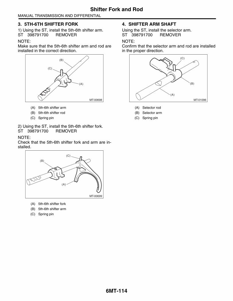
6MT-114
Shifter Fork and RodMANUAL TRANSMISSION AND DIFFERENTIAL
3. 5TH-6TH SHIFTER FORK1) Using the ST, install the 5th-6th shifter arm.ST 398791700 REMOVER
NOTE:Make sure that the 5th-6th shifter arm and rod areinstalled in the correct direction.
2) Using the ST, install the 5th-6th shifter fork.ST 398791700 REMOVER
NOTE:Check that the 5th-6th shifter fork and arm are in-stalled.
4. SHIFTER ARM SHAFTUsing the ST, install the selector arm.ST 398791700 REMOVER
NOTE:Confirm that the selector arm and rod are installedin the proper direction.
(A) 5th-6th shifter arm
(B) 5th-6th shifter rod
(C) Spring pin
(A) 5th-6th shifter fork
(B) 5th-6th shifter arm
(C) Spring pin
MT-00698
(C)
(B)
(A)
MT-00699
(C)
(B)
(A)
(A) Selector rod
(B) Selector arm
(C) Spring pin
MT-01096
(B)
(A)
(C)

6MT-115
Shifter Fork and RodMANUAL TRANSMISSION AND DIFFERENTIAL
5. STRIKING ROD1) Using the ST, install the reverse interlock armand interlock arm.ST 398791700 REMOVER
NOTE:• Confirm that the reverse interlock arm and rodare installed in the proper direction.• Confirm that the interlock arm and rod are in-stalled in the proper direction.
2) Attach the reverse interlock block and interlockblock to the striking rod.
NOTE:Confirm that the reverse interlock block and inter-lock block are installed in the proper direction.
E: INSPECTION1) Check the shift shaft and shift rod for damage.Replace if damaged.2) Repair or replace the gearshift mechanism if ex-cessively worn, bent or defective in any way.
F: ADJUSTMENT1. 1ST-2ND FORK ROD SELECTIONNOTE:In the following conditions, perform the proceduresbelow.• Replacement of the 1st and 2nd driven gear• 1st and 2nd synchro ring assembly replacement• Adapter plate replacement• Driven shaft replacement• 1st-2nd hub and sleeve assembly replacement.1) Insert the drive pinion assembly into the adapterplate.
NOTE:Confirm that the thrust bearing outer race has notbeen removed and the drive pinion is not lifted.2) Set the height gauge to the adapter plate. Lowerthe height gauge indicator to the mating surface ofthe adapter plate and case, and set to zero points.ST 18853AA000 HEIGHT GAUGE
NOTE:• The adapter plate will be the base point for themeasurement. Use a scraper to remove any gasketmaterial remaining on the end face.• During measurement, do not place the heightgauge in the shaded area shown in the figure.
3) Select the main shaft snap ring. <Ref. to 6MT-79, ADJUSTMENT, Main Shaft Assembly.>
(A) Reverse interlock arm
(B) Interlock arm
(C) Spring pin
(A) Reverse interlock block
(B) Interlock block
MT-00701
(C) (C)
(B)
(A)
MT-00688
(A)(B)
MT-00582
ST
MT-00583

6MT-116
Shifter Fork and RodMANUAL TRANSMISSION AND DIFFERENTIAL
4) Measure “B1” and “B2” as shown in the figure.
5) Shift the 1st-2nd sleeve to the 1st driven gearside, push down to the stopper, and measure “B1”.
NOTE:• Set the height gauge indicator near the measure-ment target, and lock dial (1) as shown in the figure.Turn dial (2), and set the indicator to the 1st sideend surface of the sleeve.• Turn approximately 72° at a time, and measurethe sleeve in 5 locations. Round off the 2 highestand 2 lowest measurement values. The remainingcenter value is used as the measurement value.
6) Set the height gauge indicator upside down.
7) Shift the 1st-2nd sleeve to the 2nd driven gearside, push up on the stopper, and measure “B2”.
NOTE:• Set the height gauge indicator near the measure-ment target, and lock dial (1) as shown in the figure.Turn dial (2), and set the indicator to the 2nd sideend surface of the sleeve.• The measurement is to be performed with twopersons, while holding the sleeve straight.• Turn approximately 72° at a time, and measurethe sleeve in 5 locations. Round off the 2 highestand 2 lowest measurement values. The remainingcenter value is used as the measurement value.
(A) 1st driven gear
(B) 1st-2nd sleeve
MT-00979
B1B2
MT-00702(A)
(B)
MT-00585
(2)
(1)
(A) Indicator
(A) 2nd driven gear
(B) 1st-2nd sleeve
MT-00703
(A)
MT-00704
(A)
(B)
MT-00585
(2)
(1)

6MT-117
Shifter Fork and RodMANUAL TRANSMISSION AND DIFFERENTIAL
8) According to both of the measurements, calcu-late the neutral position of the 1st-2nd sleeve. Fromthe following calculation, select a fork rod whichmatches the calculated value.Calculation: T = (B1 + B2) / 2T: 1st-2nd sleeve center positionB1: Height from the adapter plate end to the sleeveend, when shifted to 1st gearB2: Measured height from the adapter plate end tothe sleeve end, when shifted to 2nd gear: +55 mm(2.17 in)
NOTE:Attach the indicator upside down in comparison tothe setting procedures for the zero point. Add “d1”[Value: 55 mm (2.17 in)] from the figure below to“B2”, and measure “B2”.
2. 3RD-4TH FORK ROD SELECTIONNOTE:In the following conditions, perform the proceduresbelow.• Main shaft replacement• 3rd, and 3rd to 6th drive gear and bushing re-placement• 3rd, and 3rd to 6th synchro assembly replace-ment• 3rd-4th hub and sleeve assembly replacement1) Insert the main shaft assembly into the adapterplate.2) Set the height gauge to the adapter plate. Lowerthe height gauge indicator to the top surface of thesnap ring groove, and set to the zero point on theupper side of the main rear bearing.ST 18853AA000 HEIGHT GAUGE
NOTE:• The height gauge will be set on the adapter plateduring the measurement. Use a scraper to removeany gasket material remaining on the end face.• During measurement, do not place the heightgauge in the shaded area shown in the figure.
T mm (in) Lot No. (marking)
62.63 — 62.93(2.4657 — 2.4776)
32801AA240 (3)
62.93 — 63.23(2.4776 — 2.4894)
32801AA180 (1)
63.23 — 63.53(2.4894 — 2.5012)
32801AA190 (none)
MT-00705
d1
(A) Ball bearing
MT-00706
(A)
MT-00583
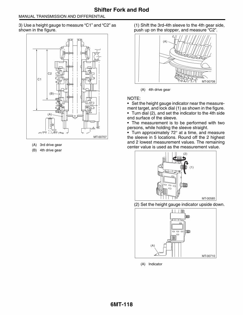
6MT-118
Shifter Fork and RodMANUAL TRANSMISSION AND DIFFERENTIAL
3) Use a height gauge to measure “C1” and “C2” asshown in the figure.
(1) Shift the 3rd-4th sleeve to the 4th gear side,push up on the stopper, and measure “C2”.
NOTE:• Set the height gauge indicator near the measure-ment target, and lock dial (1) as shown in the figure.• Turn dial (2), and set the indicator to the 4th sideend surface of the sleeve.• The measurement is to be performed with twopersons, while holding the sleeve straight.• Turn approximately 72° at a time, and measurethe sleeve in 5 locations. Round off the 2 highestand 2 lowest measurement values. The remainingcenter value is used as the measurement value.
(2) Set the height gauge indicator upside down.
(A) 3rd drive gear
(B) 4th drive gear
MT-00707
C1
C2
(A)
(B)(A) 4th drive gear
(A) Indicator
MT-00708
(A)
MT-00585
(2)
(1)
MT-00710
(A)

6MT-119
Shifter Fork and RodMANUAL TRANSMISSION AND DIFFERENTIAL
(3) Shift the 3rd-4th sleeve to the 3rd drive gearside, push down to the stopper, and measure“C1”.
NOTE:• Set the height gauge indicator near the measure-ment target, and lock dial (1) as shown in the figure.Turn dial (2), and set the indicator to the 3rd sideend surface of the sleeve.• Turn approximately 72° at a time, and measurethe sleeve in 5 locations. Round off the 2 highestand 2 lowest measurement values. The remainingcenter value is used as the measurement value.
4) According to both of the measurements, calcu-late the neutral position of the 3rd-4th sleeve. Fromthe following calculation, select a fork rod whichmatches the calculated value.Calculation: T = (C1 + C2) / 2T: 3rd-4th sleeve center positionC1: Measured depth from the main shaft rear bear-ing snap ring groove to the sleeve end, when shift-ed to 3rd gear: +55 mm (2.17 in)C2: Measured depth from the main shaft rear bear-ing snap ring groove to the sleeve end, when shift-ed to 4th gear
NOTE:Attach the indicator upside down in comparison tothe setting procedures for the zero point. Add “d1”[Value: 55 mm (2.17 in)] from the figure below to“C1”, and measure “C1”.
(A) 3rd drive gear
MT-00711
(A)
MT-00585
(2)
(1)
T mm (in)
Lot No. (marking)
M.SFTSnap ring805072010[t = 1.65 mm (0.065 in)]
M.SFTSnap ring805072011[t = 1.95 mm (0.077 in)]
M.SFTSnap ring805072012[t = 2.25 mm (0.089 in)]
137.22 — 137.52
(5.4024 — 5.4142)
32809AA171 (none)
32809AA181 (2)
32809AA191 (4)
137.52 — 137.82
(5.4142 — 5.4260)
32809AA161 (1)
32809AA171 (none)
32809AA181 (2)
137.82 — 138.12
(5.4260 — 5.4379)
32809AA141 (3)
32809AA161 (1)
32809AA171 (none)
T = Thickness
MT-00705
d1

6MT-120
Shifter Fork and RodMANUAL TRANSMISSION AND DIFFERENTIAL
3. 5TH-6TH FORK ROD SELECTIONNOTE:In the following conditions, perform the proceduresbelow.• Main shaft replacement• 3rd to 6th drive gear and bushing replacement• 3rd to 6th synchro ring assembly replacement• 3rd-4th hub and sleeve assembly replacement• 5th-6th hub and sleeve assembly replacement1) Insert the main shaft assembly into the adapterplate.2) Set the height gauge to the adapter plate. Lowerthe height gauge indicator to the upper face of thesnap ring groove or the upper side of the main rearbearing. Set to zero point.ST 18853AA000 HEIGHT GAUGE
NOTE:• The height gauge will be set on the adapter plateduring the measurement. Use a scraper to removeany gasket material remaining on the end face.• During measurement, do not place the heightgauge in the shaded area shown in the figure.
3) Use a height gauge to measure “D1” and “D2” asshown in the figure.
(A) Ball bearing
MT-00706
(A)
MT-00583
(A) 5th main gear
(B) 6th main gear
MT-00712
D1
D2
(A)
(B)

6MT-121
Shifter Fork and RodMANUAL TRANSMISSION AND DIFFERENTIAL
(1) Shift the 5th-6th sleeve to the 6th main gearside, push up on the stopper, and measure“D2”.
NOTE:• Set the height gauge indicator near the measure-ment target, and lock dial (1) as shown in the figure.Turn dial (2), and set the indicator to the 6th sideend surface of the sleeve.• The measurement is to be performed with twopersons, while holding the sleeve straight.• Turn approximately 72° at a time, and measurethe sleeve in 5 locations. Round off the 2 highestand 2 lowest measurement values. The remainingcenter value is used as the measurement value.
(2) Set the height gauge indicator upside down.
(3) Shift the 5th-6th sleeve to the 5th main gearside, push down to the stopper, and measure“D1”.
NOTE:• Set the height gauge indicator near the measure-ment target, and lock dial (1) as shown in the figure.Turn dial (2), and set the indicator to the 5th sideend surface of the sleeve.• Turn approximately 72° at a time, and measurethe sleeve in 5 locations. Round off the 2 highestand 2 lowest measurement values. The remainingcenter value is used as the measurement value.
(A) 6th main gear
(A) Indicator
MT-00713
(A)
MT-00585
(2)
(1)
MT-00710
(A)
(A) 5th main gear
MT-00714
(A)
MT-00585
(2)
(1)

6MT-122
Shifter Fork and RodMANUAL TRANSMISSION AND DIFFERENTIAL
4) According to both of the measurements, calcu-late the neutral position of the 5th-6th sleeve. Fromthe following calculation, select a fork rod whichmatches the calculated value.Calculation: T = (D1 + D2) / 2T: 5th-6th sleeve center positionD1: Measured length from the shaft rear bearingsnap ring groove to the sleeve groove end, whenshifted to 5th gear [Value: +55 mm (2.17 in)]D2: Measured length from the main shaft rear bear-ing snap ring groove to the sleeve groove end,when shifted to 6th gear
NOTE:Attach the indicator upside down in comparison tothe setting procedures for the zero point. Add “d1”[Value: 55 mm (2.17 in)] from the figure below to“D1”, and measure “D1”.
4. REVERSE FORK ROD SELECTIONNOTE:In the following conditions, perform the proceduresbelow.• Reverse idler gear replacement.• Reverse idler gear No. 2 replacement.• Adapter plate replacement.• Base replacement.1) Insert the reverse idler gear assembly into theadapter plate.2) Tighten the base COMPL attachment bolts.
Tightening torque:25 N·m (2.5 kgf-m, 18.4 ft-lb)
3) Set the height gauge to the adapter plate. Lowerthe height gauge indicator to the mating surface ofthe adapter plate and case, and set to zero points.ST 18853AA000 HEIGHT GAUGE
NOTE:• The adapter plate will be the base point for themeasurement. Use a scraper to remove any gasketmaterial remaining on the end face.• During measurement, do not place the heightgauge in the shaded area shown in the figure.
T mm (in)
Lot No. (marking)
M.SFTSnap ring805072010[t = 1.65 mm (0.065 in)]
M.SFTSnap ring805072011[t = 1.95 mm (0.077 in)]
M.SFTSnap ring805072012[t = 2.25 mm (0.089 in)]
64.12 — 64.42
(2.5244 — 2.5362)
32945AA021 (none)
32945AA031 (2)
32945AA041 (4)
64.42 — 64.72
(2.5362 — 2.5480)
32945AA011 (1)
32945AA021 (none)
32945AA031 (2)
64.72 — 65.02
(2.5480 — 2.5598)
32945AA001 (3)
32945AA011 (1)
32945AA021 (none)
T = Thickness
MT-00705
d1
MT-00546
MT-00582
ST
MT-00583
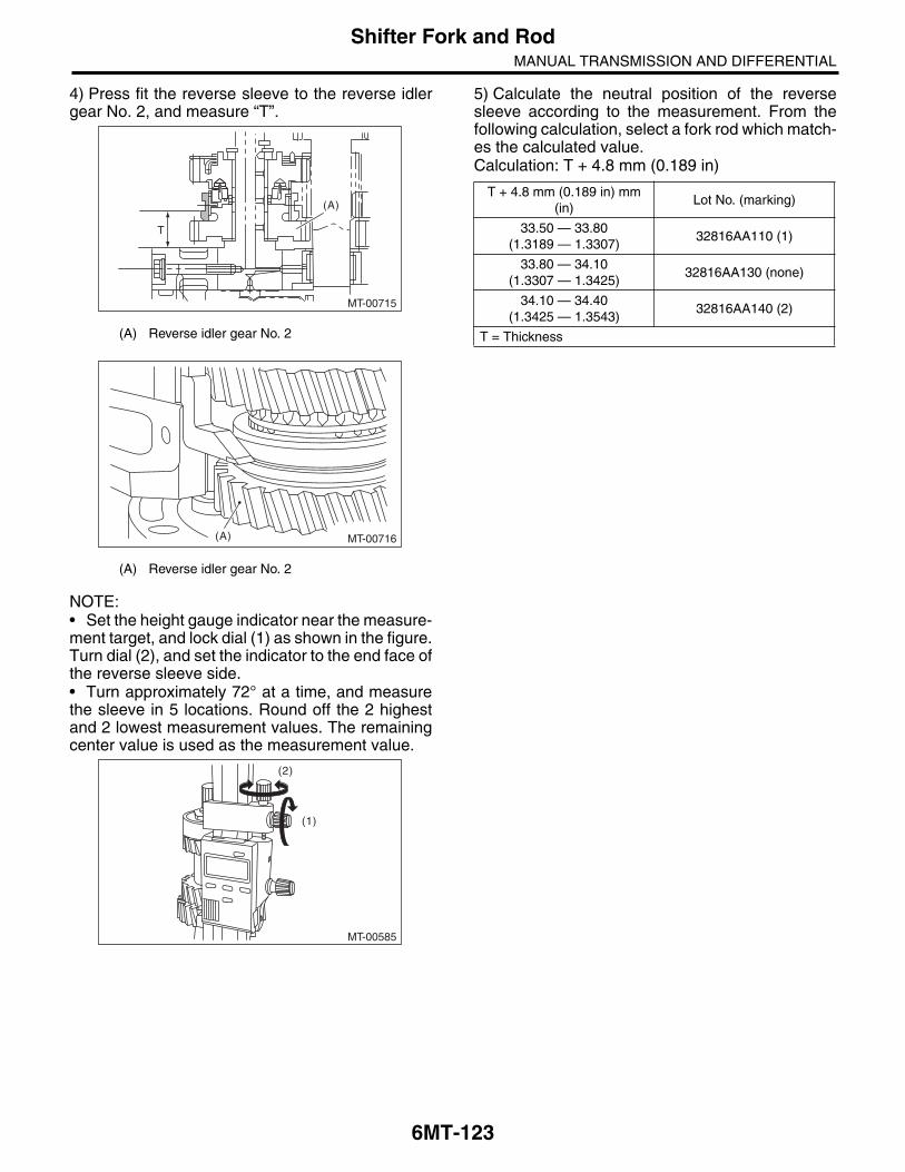
6MT-123
Shifter Fork and RodMANUAL TRANSMISSION AND DIFFERENTIAL
4) Press fit the reverse sleeve to the reverse idlergear No. 2, and measure “T”.
NOTE:• Set the height gauge indicator near the measure-ment target, and lock dial (1) as shown in the figure.Turn dial (2), and set the indicator to the end face ofthe reverse sleeve side.• Turn approximately 72° at a time, and measurethe sleeve in 5 locations. Round off the 2 highestand 2 lowest measurement values. The remainingcenter value is used as the measurement value.
5) Calculate the neutral position of the reversesleeve according to the measurement. From thefollowing calculation, select a fork rod which match-es the calculated value.Calculation: T + 4.8 mm (0.189 in)
(A) Reverse idler gear No. 2
(A) Reverse idler gear No. 2
MT-00715
(A)
T
MT-00716(A)
MT-00585
(2)
(1)
T + 4.8 mm (0.189 in) mm (in)
Lot No. (marking)
33.50 — 33.80(1.3189 — 1.3307)
32816AA110 (1)
33.80 — 34.10(1.3307 — 1.3425)
32816AA130 (none)
34.10 — 34.40(1.3425 — 1.3543)
32816AA140 (2)
T = Thickness
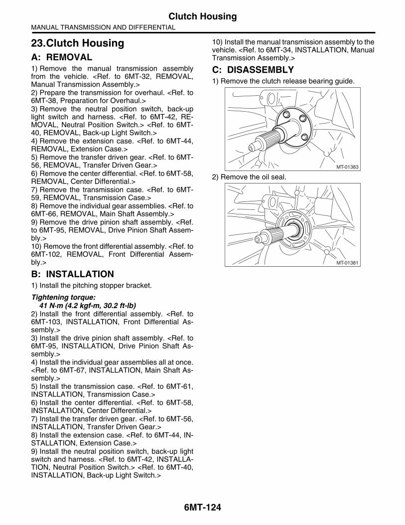
6MT-124
Clutch HousingMANUAL TRANSMISSION AND DIFFERENTIAL
23.Clutch HousingA: REMOVAL1) Remove the manual transmission assemblyfrom the vehicle. <Ref. to 6MT-32, REMOVAL,Manual Transmission Assembly.>2) Prepare the transmission for overhaul. <Ref. to6MT-38, Preparation for Overhaul.>3) Remove the neutral position switch, back-uplight switch and harness. <Ref. to 6MT-42, RE-MOVAL, Neutral Position Switch.> <Ref. to 6MT-40, REMOVAL, Back-up Light Switch.>4) Remove the extension case. <Ref. to 6MT-44,REMOVAL, Extension Case.>5) Remove the transfer driven gear. <Ref. to 6MT-56, REMOVAL, Transfer Driven Gear.>6) Remove the center differential. <Ref. to 6MT-58,REMOVAL, Center Differential.>7) Remove the transmission case. <Ref. to 6MT-59, REMOVAL, Transmission Case.>8) Remove the individual gear assemblies. <Ref. to6MT-66, REMOVAL, Main Shaft Assembly.>9) Remove the drive pinion shaft assembly. <Ref.to 6MT-95, REMOVAL, Drive Pinion Shaft Assem-bly.>10) Remove the front differential assembly. <Ref. to6MT-102, REMOVAL, Front Differential Assem-bly.>
B: INSTALLATION1) Install the pitching stopper bracket.
Tightening torque:41 N·m (4.2 kgf-m, 30.2 ft-lb)
2) Install the front differential assembly. <Ref. to6MT-103, INSTALLATION, Front Differential As-sembly.>3) Install the drive pinion shaft assembly. <Ref. to6MT-95, INSTALLATION, Drive Pinion Shaft As-sembly.>4) Install the individual gear assemblies all at once.<Ref. to 6MT-67, INSTALLATION, Main Shaft As-sembly.>5) Install the transmission case. <Ref. to 6MT-61,INSTALLATION, Transmission Case.>6) Install the center differential. <Ref. to 6MT-58,INSTALLATION, Center Differential.>7) Install the transfer driven gear. <Ref. to 6MT-56,INSTALLATION, Transfer Driven Gear.>8) Install the extension case. <Ref. to 6MT-44, IN-STALLATION, Extension Case.>9) Install the neutral position switch, back-up lightswitch and harness. <Ref. to 6MT-42, INSTALLA-TION, Neutral Position Switch.> <Ref. to 6MT-40,INSTALLATION, Back-up Light Switch.>
10) Install the manual transmission assembly to thevehicle. <Ref. to 6MT-34, INSTALLATION, ManualTransmission Assembly.>
C: DISASSEMBLY1) Remove the clutch release bearing guide.
2) Remove the oil seal.
MT-01383
MT-01381

6MT-125
Clutch HousingMANUAL TRANSMISSION AND DIFFERENTIAL
D: ASSEMBLY1) Attach the oil seal to the clutch housing, beingcareful not to damage the seal.
NOTE:Use a new oil seal.ST 18657AA020 OIL SEAL INSTALLER
2) Install the clutch release bearing guide.
Tightening torque:6.4 N·m (0.7 kgf-m, 4.7 ft-lb)
E: INSPECTION1) Check to make sure there is no damage orcracks on the clutch housing. If there is excessivedamage, replace the clutch housing.2) Inspect the clutch housing for transmission gearoil leakage. If any oil leaks are found, repair or re-place the applicable part.
MT-01382
ST
MT-01383

6MT-126
Driver’s Control Center Differential Control ModuleMANUAL TRANSMISSION AND DIFFERENTIAL
24.Driver’s Control Center Differential Control Module
A: REMOVAL1) Disconnect the ground cable from the battery.2) Remove the instrument panel lower. <Ref. to EI-46, INSTRUMENT PANEL LOWER, REMOVAL,Center Console.>3) Remove the driver’s control center differentialcontrol module by disconnecting the connector.
B: INSTALLATIONInstall in the reverse order of removal.
Tightening torque:15 N·m (1.5 kgf-m, 11.1 ft-lb)
(A) Driver’s control center differential control mod-ule
MT-01742
(A)

6MT-127
General Diagnostic TableMANUAL TRANSMISSION AND DIFFERENTIAL
25.General Diagnostic TableA: INSPECTION1. MANUAL TRANSMISSION
Symptom Possible cause Corrective action
1. Gears are difficult to engage.NOTE:If it is difficult to shift, there are two possi-ble causes. One is a defective gear shift system and the other is defective trans-mission. However, if the operation is heavy and engagement of the gears is dif-ficult, a defective clutch function may also be responsible. Check whether the clutch is correctly functioning, before checking the gear shift system and transmission.
(a) Worn, damaged or burred chamfer at internal spline of the sleeve
Replace.
(b) Gear spline wear, damage, dents Replace.
(c) Worn or scratched bushings Replace.
(d) Incorrect contact or wear between synchronizer ring and gear cone
Repair or replace.
2. Gear slip-out• Gear slips out when coasting on rough road.• Gear slips out during acceleration.
(a) Defective pitching stopper adjustment Adjust.
(b) Loose engine mounting bolts Tighten or replace.
(c) Worn fork shifter, broken shifter fork rail spring
Replace.
(d) Worn or damaged ball bearing Replace.
(e) Excessive clearance between splines of synchronizer hub and synchronizer sleeve
Replace.
(f) Worn in the synchronizer hub chamfer angle
Replace.
(g) Worn 1st driven gear, needle bearing and race
Replace.
(h) Worn 2nd driven gear, needle bearing and race
Replace.
(i) Worn 3rd drive gear and bushing Replace.
(j) Worn 4th drive gear and bushing Replace.
(k) Worn 5th drive gear and bushing Replace.
(l) Worn 6th drive gear and bushing Replace.
(m) Worn reverse idler gear and bushing Replace.
3. Abnormal noise emitted from transmis-sion
NOTE:If a noise is heard when the vehicle is parked with its engine idling and ceases when the clutch is disengaged, it may be considered that the noise is coming from the transmission.
(a) Insufficient or improper lubrication Replenish or replace with the specified amount of recommended oil.
(b) Worn or damaged gears and bearings
NOTE:If the trouble is only wear of the gear teeth surfaces, only a high whirring noise will occur at high speeds, but if any part is bro-ken, rhythmical clicking sounds will be heard even at low speeds.
Replace.

6MT-128
General Diagnostic TableMANUAL TRANSMISSION AND DIFFERENTIAL
2. DIFFERENTIAL
Symptom Possible cause Corrective action
1. Broken differential (case, gear, bearing, etc.)
NOTE:Noise will occur, and eventually the differ-ential will not be able to operate due to broken pieces obstructing the gear revo-lution.
(a) Insufficient or improper oil Disassemble the differential and replace broken components. At the same time check other components for any trouble, and replace if necessary.
(b) Use of vehicle under severe condi-tions such as excessive load and improper use of the clutch
Readjust the preload and backlash of the bearing, and the contact surface of gear.
(c) Improper adjustment of taper roller bearing
Adjust.
(d) Improper adjustment of the drive pin-ion and the hypoid driven gear
Adjust.
(e) Loose hypoid driven gear clamping bolts
Tighten.
2. Differential and hypoid gear noiseTroubles of the differential and hypoid gear always appear as noise problems. Therefore noise is the first indication of trouble. However, noise from the engine, muffler, tire, exhaust gas, bearing, body, etc. are easily mistaken for noise from the differential. Pay special attention to the hypoid gear noise because it is easily confused with other gear noises. There are the following four kinds of noises.• Gear noise when driving: If noise increases as the vehicle speed increases, it may be due to insufficient gear oil, incorrect gear engagement, damaged gears, etc.• Gear noise during coasting: Damaged gears due to misadjusted bearings and incorrect shim adjustment.• Bearing noise when driving or coasting: Cracked, broken or damaged bearings.
(a) Insufficient oil Replenish or replace with the specified amount of recommended oil.
(b) Improper adjustment of hypoid driven gear and drive pinion
Check the tooth contact.
(c) Worn teeth of hypoid driven gear and drive pinion
Replace as a set.Readjust the bearing preload.
(d) Loose roller bearing Readjust the backlash of the hypoid driven gear to drive pinion, and check the tooth contact.
(e) Distorted hypoid driven gear or differ-ential case
Replace.


![Transmission Line Differential Protection Based on ...discussed line differential protection based on IEC 61850. In [9] an adaptive current line differential protection scheme is proposed](https://img.dokumen.tips/doc/110x75/5e7b1116957fb414ac4ec632/transmission-line-differential-protection-based-on-discussed-line-differential.jpg)