Embed Size (px)
Citation preview

Introduction 1
Safety notes
2
Description
3
Operation planning
4
Mounting
5
Connection
6
Commissioning
7
Operator control
8
Parameterizing
9
Service and maintenance
10
Technical data
11
Dimensional drawings
12
Appendix
A
ESD guidelines
B
List of abbreviations
C
SENTRON
Power Monitoring DeviceSENTRON PAC3100
Manual
10/2009 A5E02385159B-01
Legal information Warning notice system
This manual contains notices you have to observe in order to ensure your personal safety, as well as to prevent damage to property. The notices referring to your personal safety are highlighted in the manual by a safety alert symbol, notices referring only to property damage have no safety alert symbol. These notices shown below are graded according to the degree of danger.
DANGER indicates that death or severe personal injury will result if proper precautions are not taken.
WARNING indicates that death or severe personal injury may result if proper precautions are not taken.
CAUTION with a safety alert symbol, indicates that minor personal injury can result if proper precautions are not taken.
CAUTION without a safety alert symbol, indicates that property damage can result if proper precautions are not taken.
NOTICE indicates that an unintended result or situation can occur if the corresponding information is not taken into account.
If more than one degree of danger is present, the warning notice representing the highest degree of danger will be used. A notice warning of injury to persons with a safety alert symbol may also include a warning relating to property damage.
Qualified Personnel The product/system described in this documentation may be operated only by personnel qualified for the specific task in accordance with the relevant documentation for the specific task, in particular its warning notices and safety instructions. Qualified personnel are those who, based on their training and experience, are capable of identifying risks and avoiding potential hazards when working with these products/systems.
Proper use of Siemens products Note the following:
WARNING Siemens products may only be used for the applications described in the catalog and in the relevant technical documentation. If products and components from other manufacturers are used, these must be recommended or approved by Siemens. Proper transport, storage, installation, assembly, commissioning, operation and maintenance are required to ensure that the products operate safely and without any problems. The permissible ambient conditions must be adhered to. The information in the relevant documentation must be observed.
Trademarks All names identified by ® are registered trademarks of the Siemens AG. The remaining trademarks in this publication may be trademarks whose use by third parties for their own purposes could violate the rights of the owner.
Disclaimer of Liability We have reviewed the contents of this publication to ensure consistency with the hardware and software described. Since variance cannot be precluded entirely, we cannot guarantee full consistency. However, the information in this publication is reviewed regularly and any necessary corrections are included in subsequent editions.
Siemens AG Industry Sector Postfach 48 48 90026 NÜRNBERG GERMANY
Ordernumber: 3ZX1012-0KM31-3AC0 Ⓟ 10/2009
Copyright © Siemens AG 2009. Technical data subject to change

SENTRON PAC3100 Manual, 10/2009, A5E02385159B-01 3
Table of contents
1 Introduction.............................................................................................................................................. 11
1.1 Purpose of this document ............................................................................................................11 1.2 Orientation aids............................................................................................................................11 1.3 Components of the product..........................................................................................................12 1.4 Latest information and correction sheet.......................................................................................12 1.5 Further documentation.................................................................................................................12
2 Safety notes............................................................................................................................................. 13 3 Description............................................................................................................................................... 15
3.1 Features .......................................................................................................................................15 3.2 Measuring inputs..........................................................................................................................17 3.3 Measured variables......................................................................................................................20 3.4 Power demands and counters .....................................................................................................21 3.4.1 Acquisition of power demand.......................................................................................................21 3.4.2 Energy counters...........................................................................................................................22 3.4.3 Behavior in the case of power failure and power restore ............................................................23 3.5 Digital inputs and outputs.............................................................................................................23 3.5.1 Digital inputs.................................................................................................................................23 3.5.2 Digital outputs ..............................................................................................................................24 3.6 RS 485 interface ..........................................................................................................................26 3.7 Slots on the rear of the device .....................................................................................................27
4 Operation planning .................................................................................................................................. 29 5 Mounting.................................................................................................................................................. 31
5.1 Unpacking ....................................................................................................................................31 5.2 Mounting on the switching panel..................................................................................................32 5.2.1 Tools ............................................................................................................................................32 5.2.2 Mounting dimensions ...................................................................................................................32 5.2.3 Installation steps ..........................................................................................................................32 5.3 Deinstallation................................................................................................................................36
6 Connection .............................................................................................................................................. 39 6.1 Safety notes .................................................................................................................................39 6.2 Connections .................................................................................................................................40 6.3 Connecting the cables to the terminals........................................................................................45 6.4 Connection examples ..................................................................................................................45 6.5 Connecting to the RS 485 bus.....................................................................................................48

Table of contents
SENTRON PAC3100 4 Manual, 10/2009, A5E02385159B-01
7 Commissioning ........................................................................................................................................ 51 7.1 Overview ..................................................................................................................................... 51 7.2 Applying the supply voltage ........................................................................................................ 51 7.3 Parameterizing the device........................................................................................................... 53 7.3.1 Setting the language ................................................................................................................... 53 7.3.2 Voltage input ............................................................................................................................... 55 7.3.2.1 Setting the connection type......................................................................................................... 55 7.3.2.2 Measurement using voltage transformers................................................................................... 56 7.3.2.3 Setting the conversion ratio of the voltage transformer .............................................................. 57 7.3.2.4 Setting the voltage input.............................................................................................................. 58 7.3.3 Current input ............................................................................................................................... 59 7.3.3.1 Setting the conversion ratio of the current transformer............................................................... 59 7.3.4 RS 485 interface ......................................................................................................................... 60 7.4 Applying the measuring voltage.................................................................................................. 61 7.5 Applying the measuring current .................................................................................................. 61 7.6 Checking the displayed measured values .................................................................................. 62
8 Operator control....................................................................................................................................... 63 8.1 Device interface .......................................................................................................................... 63 8.1.1 Displays and operator controls ................................................................................................... 63 8.1.2 Display of the measured variables.............................................................................................. 69 8.1.3 Display of the "MAIN MENU" ...................................................................................................... 71 8.1.4 Display of the "SETTINGS" menu............................................................................................... 73 8.1.5 Display of the device settings ..................................................................................................... 74 8.1.6 Edit mode of the device settings ................................................................................................. 75 8.2 Steps ........................................................................................................................................... 76 8.2.1 Operator input steps in the measured variable display............................................................... 76 8.2.2 Operator input steps in the "MAIN MENU" ................................................................................. 78 8.2.3 Operator input steps in the "SETTINGS" menu.......................................................................... 79 8.2.4 Operator input steps in device settings display........................................................................... 79 8.2.5 Operator input steps in edit mode of the device settings............................................................ 80
9 Parameterizing......................................................................................................................................... 83 9.1 Introduction ................................................................................................................................. 83 9.2 Parameterizing the operator interface......................................................................................... 83 9.2.1 Groups of settings ....................................................................................................................... 83 9.2.2 Device information ...................................................................................................................... 84 9.2.3 Language and regional settings.................................................................................................. 85 9.2.4 Basic parameters ........................................................................................................................ 85 9.2.5 Power demand ............................................................................................................................ 88 9.2.6 Energy counters .......................................................................................................................... 89 9.2.7 Integrated I/Os ............................................................................................................................ 89 9.2.8 Communication ........................................................................................................................... 91 9.2.9 Display......................................................................................................................................... 92 9.2.10 Advanced .................................................................................................................................... 93 9.2.11 Password management .............................................................................................................. 95 9.2.11.1 Calling password management................................................................................................... 96 9.2.11.2 Switch on password protection ................................................................................................... 96 9.2.11.3 Switch off password protection ................................................................................................... 97 9.2.11.4 Change password ....................................................................................................................... 98 9.2.11.5 Password lost - what to do?........................................................................................................ 99

Table of contents
SENTRON PAC3100 Manual, 10/2009, A5E02385159B-01 5
10 Service and maintenance ...................................................................................................................... 101 10.1 Calibration..................................................................................................................................101 10.2 Cleaning .....................................................................................................................................101 10.3 Firmware updates ......................................................................................................................101 10.4 Repair.........................................................................................................................................102 10.5 Disposal .....................................................................................................................................103
11 Technical data ....................................................................................................................................... 105 11.1 Technical data............................................................................................................................105 11.2 Labeling......................................................................................................................................113
12 Dimensional drawings............................................................................................................................ 115 A Appendix................................................................................................................................................ 119
A.1 Measured variables....................................................................................................................119 A.2 Modbus RTU..............................................................................................................................125 A.2.1 Structure of the job message frame...........................................................................................125 A.2.2 Character frame .........................................................................................................................126 A.2.3 Function codes...........................................................................................................................126 A.2.4 Exception codes.........................................................................................................................128 A.2.5 Modbus measured variables with the function codes 0x03 and 0x04 .......................................129 A.2.6 Structure - Digital input status and digital output status with the function codes 0x03 and
0x04 ...........................................................................................................................................132 A.2.7 Structure - Device diagnostics and device status with the function codes 0x03 and 0x04 .......133 A.2.8 Modbus status parameters with the function code 0x02 ...........................................................133 A.2.9 Modbus settings with the function codes 0x03, 0x04 and 0x10 ................................................134 A.2.10 MODBUS communication parameter with the function codes 0x03, 0x04 and 0x10................136 A.2.11 Modbus device information with the function codes 0x03, 0x04 and 0x10 ...............................137 A.2.12 Modbus command parameters ..................................................................................................138 A.2.13 MODBUS standard device identification with the function code 0x2B ......................................139 A.3 Correction sheet.........................................................................................................................139
B ESD guidelines ...................................................................................................................................... 141 B.1 Electrostatic sensitive devices (ESD) ........................................................................................141
C List of abbreviations............................................................................................................................... 143 C.1 Abbreviations .............................................................................................................................143
Glossary ................................................................................................................................................ 145 Index...................................................................................................................................................... 147
Tables
Table 3- 1 Device versions............................................................................................................................15 Table 3- 2 Available connection types ..........................................................................................................18 Table 3- 3 Display of the measured variables depending on the connection type .......................................19 Table 3- 4 Measured variables......................................................................................................................20 Table 3- 5 Default Modbus RTU communication settings.............................................................................26

Table of contents
SENTRON PAC3100 6 Manual, 10/2009, A5E02385159B-01
Table 3- 6 Meaning of the LED signals ........................................................................................................ 27 Table 4- 1 Environmental conditions ............................................................................................................ 30 Table 7- 1 Connection of supply voltage...................................................................................................... 52 Table 7- 2 Available connection types.......................................................................................................... 55 Table 8- 1 Assignments of the function keys in the "MAIN MENU" ............................................................. 72 Table 8- 2 Assignments of the function keys in the "SETTINGS" menu...................................................... 73 Table 8- 3 Assignments of the function keys in the device settings display ................................................ 74 Table 8- 4 Assignments of the function keys in edit mode of the device settings........................................ 76 Table A- 1 Load profile ............................................................................................................................... 123 Table A- 2 Designations of the measured variables on the display ........................................................... 124 Table A- 3 Designations of the measured value properties on the display ................................................ 124 Table A- 4 Structure of the message frame................................................................................................ 125 Table A- 5 Supported function codes ......................................................................................................... 127 Table A- 6 MODBUS exception codes ....................................................................................................... 128 Table A- 7 Available measured variables ................................................................................................... 129 Table A- 8 Structure - Status of the digital inputs and outputs, Modbus Offset 207 and 209 .................... 132 Table A- 9 Modbus offset 205, tab 2: Structure device status and device diagnostics .............................. 133 Table A- 10 Status parameters..................................................................................................................... 133 Table A- 11 Settings parameters .................................................................................................................. 134 Table A- 12 Settings parameter for the digital output DO 0.0....................................................................... 134 Table A- 13 Settings parameter for the digital output DO 0.1....................................................................... 135 Table A- 14 Settings parameter for the language and the phase labels ...................................................... 135 Table A- 15 Settings parameter for the display ............................................................................................ 136 Table A- 16 Communication parameters ...................................................................................................... 136 Table A- 17 I&M 0 parameters with the function codes 0x03 and 0x04 ....................................................... 137 Table A- 18 I&M 1-4 parameters with the function codes 0x03, 0x04 and 0x10.......................................... 138 Table A- 19 Command parameters .............................................................................................................. 138 Table A- 20 MODBUS standard device identification parameters ............................................................... 139 Table A- 21 Errors, comments, and suggestions for improvements ............................................................ 140 Table C- 1 Meaning of abbreviations.......................................................................................................... 143
Figures
Figure 2-1 Safety-related symbols on the device ......................................................................................... 13 Figure 3-1 Display of the measured voltage in the case of connection type 3P4W..................................... 18 Figure 3-2 Display of the measuring voltage in the case of connection type 3P3W .................................... 18

Table of contents
SENTRON PAC3100 Manual, 10/2009, A5E02385159B-01 7
Figure 3-3 Indicating overload on the display ...............................................................................................19 Figure 3-4 Display of the measurable maximum value at overload ..............................................................20 Figure 3-5 Block diagram: Digital inputs........................................................................................................23 Figure 3-6 Digital inputs with switch and internal power supply on terminal DIC..........................................24 Figure 3-7 Digital inputs with switch, internal power supply, and additional external power supply on
terminal DIC .................................................................................................................................24 Figure 3-8 Energy pulse output .....................................................................................................................25 Figure 3-9 Pulse length and turn-off time......................................................................................................25 Figure 3-10 Non-usable housing openings .....................................................................................................28 Figure 4-1 Mounting position.........................................................................................................................29 Figure 5-1 Deinstallation, releasing the locking hooks..................................................................................37 Figure 6-1 Connection designations, view of the rear and top of the device ................................................41 Figure 6-2 Terminal labeling..........................................................................................................................42 Figure 6-3 Terminal labeling..........................................................................................................................43 Figure 6-4 Terminal block with 2 digital inputs and outputs, functional ground ............................................43 Figure 6-5 Connecting cables to the screw terminal .....................................................................................45 Figure 6-6 Connection type 3P4W, without voltage transformer, with three current transformers ...............46 Figure 6-7 Connection type 3P4W, with voltage transformer, with three current transformers ....................46 Figure 6-8 Connection type 3P3W, without voltage transformer, with three current transformers ...............47 Figure 6-9 Connection type 3P3W, with voltage transformer, with three current transformers ....................47 Figure 6-10 Connection type 3P3W, with voltage transformer, with three current transformers ....................48 Figure 6-11 RS 485 terminal block..................................................................................................................49 Figure 6-12 Block diagram: General RS 485 topology....................................................................................49 Figure 6-13 Bus termination using external resistor........................................................................................50 Figure 7-1 Language selection......................................................................................................................53 Figure 7-2 "SETTINGS" menu.......................................................................................................................54 Figure 7-3 "LANGUAGE" edit mode..............................................................................................................54 Figure 7-4 "CONNECTION TYPE" device setting.........................................................................................55 Figure 7-5 "USE PTs?" device setting...........................................................................................................56 Figure 7-6 "USE PTs?" device setting switched on ......................................................................................57 Figure 7-7 "VOLTAGE INPUTS" device setting ............................................................................................58 Figure 7-8 "VOLTAGE INPUTS" device setting ............................................................................................58 Figure 7-9 "CURRENT INPUTS" device setting............................................................................................59 Figure 7-10 Device setting "CURRENT INPUTS - CT PRIMARY?" ...............................................................60 Figure 8-1 Device interface ...........................................................................................................................63 Figure 8-2 Information structure and navigation ...........................................................................................65 Figure 8-3 Scroll bar of the menu list ............................................................................................................66
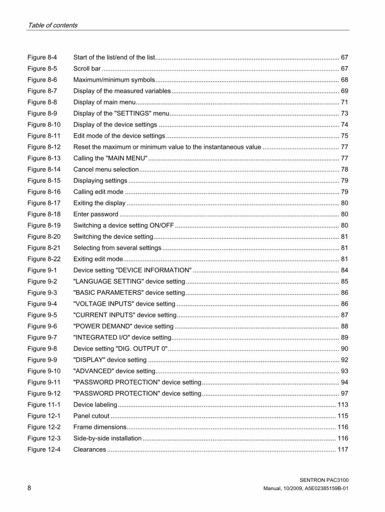
Table of contents
SENTRON PAC3100 8 Manual, 10/2009, A5E02385159B-01
Figure 8-4 Start of the list/end of the list....................................................................................................... 67 Figure 8-5 Scroll bar ..................................................................................................................................... 67 Figure 8-6 Maximum/minimum symbols....................................................................................................... 68 Figure 8-7 Display of the measured variables.............................................................................................. 69 Figure 8-8 Display of main menu.................................................................................................................. 71 Figure 8-9 Display of the "SETTINGS" menu............................................................................................... 73 Figure 8-10 Display of the device settings ..................................................................................................... 74 Figure 8-11 Edit mode of the device settings ................................................................................................. 75 Figure 8-12 Reset the maximum or minimum value to the instantaneous value ........................................... 77 Figure 8-13 Calling the "MAIN MENU" ........................................................................................................... 77 Figure 8-14 Cancel menu selection................................................................................................................ 78 Figure 8-15 Displaying settings ...................................................................................................................... 79 Figure 8-16 Calling edit mode ........................................................................................................................ 79 Figure 8-17 Exiting the display ....................................................................................................................... 80 Figure 8-18 Enter password ........................................................................................................................... 80 Figure 8-19 Switching a device setting ON/OFF ............................................................................................ 80 Figure 8-20 Switching the device setting........................................................................................................ 81 Figure 8-21 Selecting from several settings ................................................................................................... 81 Figure 8-22 Exiting edit mode......................................................................................................................... 81 Figure 9-1 Device setting "DEVICE INFORMATION" .................................................................................. 84 Figure 9-2 "LANGUAGE SETTING" device setting...................................................................................... 85 Figure 9-3 "BASIC PARAMETERS" device setting...................................................................................... 86 Figure 9-4 "VOLTAGE INPUTS" device setting ........................................................................................... 86 Figure 9-5 "CURRENT INPUTS" device setting........................................................................................... 87 Figure 9-6 "POWER DEMAND" device setting ............................................................................................ 88 Figure 9-7 "INTEGRATED I/O" device setting.............................................................................................. 89 Figure 9-8 Device setting "DIG. OUTPUT 0"................................................................................................ 90 Figure 9-9 "DISPLAY" device setting ........................................................................................................... 92 Figure 9-10 "ADVANCED" device setting....................................................................................................... 93 Figure 9-11 "PASSWORD PROTECTION" device setting............................................................................. 94 Figure 9-12 "PASSWORD PROTECTION" device setting............................................................................. 97 Figure 11-1 Device labeling.......................................................................................................................... 113 Figure 12-1 Panel cutout .............................................................................................................................. 115 Figure 12-2 Frame dimensions..................................................................................................................... 116 Figure 12-3 Side-by-side installation ............................................................................................................ 116 Figure 12-4 Clearances ................................................................................................................................ 117

Table of contents
SENTRON PAC3100 Manual, 10/2009, A5E02385159B-01 9
Figure A-1 11-bit character frame................................................................................................................126 Figure A-2 10-bit character frame................................................................................................................126

Table of contents
SENTRON PAC3100 10 Manual, 10/2009, A5E02385159B-01

SENTRON PAC3100 Manual, 10/2009, A5E02385159B-01 11
Introduction 11.1 Purpose of this document
This present manual describes the SENTRON PAC3100 Power Monitoring Device. It is intended for the use of: ● Planners ● Plant operators ● Commissioning engineers ● Service and maintenance personnel
Required basic knowledge A general knowledge of the field of electrical engineering is required to understand this manual. Knowledge of the relevant safety regulations and standards is required for installing and connecting the device.
Validity range Those device properties valid at the time of publication of the manual are described.
1.2 Orientation aids
General information The manual includes the following orientation aids: ● Table of contents ● List of figures and tables ● List of abbreviations ● Glossary ● Index

Introduction 1.3 Components of the product
SENTRON PAC3100 12 Manual, 10/2009, A5E02385159B-01
1.3 Components of the product
Description The package includes: ● 1 SENTRON PAC3100 ● 2 brackets for panel mounting ● 1 plug-in terminal block for RS 485 connection ● 1 SENTRON PAC3100 Operating Instructions
1.4 Latest information and correction sheet
Up-to-the-minute information You can obtain further assistance by calling the following numbers: Technical Assistance: Phone: +49 (0) 911-895-5900 (8:00 – 17:00 CET) Fax: +49 (0) 911-895-5907
On the Internet at: E-mail: Technical Assistance (mailto:[email protected]) Internet: Technical Assistance (http://www.siemens.de/lowvoltage/technical-assistance)
Correction sheet A correction sheet is included at the end of the manual. Please use it to record your suggestions for improvements, additions and corrections, and return the sheet to us. This will help us to improve the next edition of the manual.
1.5 Further documentation
Overview You can find more information in the "SENTRON PAC3100" Operating Instructions and on the Internet.
See also Latest information and correction sheet (Page 12)

SENTRON PAC3100 Manual, 10/2009, A5E02385159B-01 13
Safety notes 2General safety notes
DANGER
Hazardous Voltage Will cause death or serious injury. Turn off and lock out all power supplying this device before working on this device.
Safety-related symbols on the device
N117
Figure 2-1 Safety-related symbols on the device

Safety notes
SENTRON PAC3100 14 Manual, 10/2009, A5E02385159B-01
Symbol Meaning (1)
Risk of electric shock
(2)
General Warning Symbol
See also Applying the supply voltage (Page 51) Applying the measuring voltage (Page 61) Applying the measuring current (Page 61)

SENTRON PAC3100 Manual, 10/2009, A5E02385159B-01 15
Description 33.1 Features
The SENTRON PAC3100 is a Power Monitoring Device for displaying the basic electrical variables in low-voltage power distribution. It is capable of single-phase, two-phase, or three-phase measurement and can be used in three-wire, four-wire, TN, TT, and IT systems. Thanks to its compact design in 96 x 96 mm format, it is an ideal replacement for all conventional analog indicating instruments. Thanks to its large measuring voltage range, the SENTRON PAC3100 can be connected direct in any low-voltage system up to a rated voltage of 480 VL-L. Higher voltages can be measured using voltage transformers. x / 5 A current transformers can be used for current measuring. The large graphical LC display permits reading even from a distance. The combination of four function keys with the multi-language plaintext displays makes intuitive user prompting possible. The experienced operator can also use direct navigation for quicker selection of the desired display menu. The integrated RS 485 interface can be used for communication. In addition, the SENTRON PAC3100 has 2 digital inputs and 2 digital outputs. The parameters can be set either direct on the device or via the RS 485 interface. Password protection is integrated via the front of the device to guard against unauthorized access.
Device versions The device is available in the following version:
Table 3- 1 Device versions
SENTRON PAC3100 Power Monitoring Device Order No. Description 7KM3133-0BA00-3AA0 SENTRON PAC3100 with wide-range power supply and screw terminals
Description 3.1 Features
SENTRON PAC3100 16 Manual, 10/2009, A5E02385159B-01
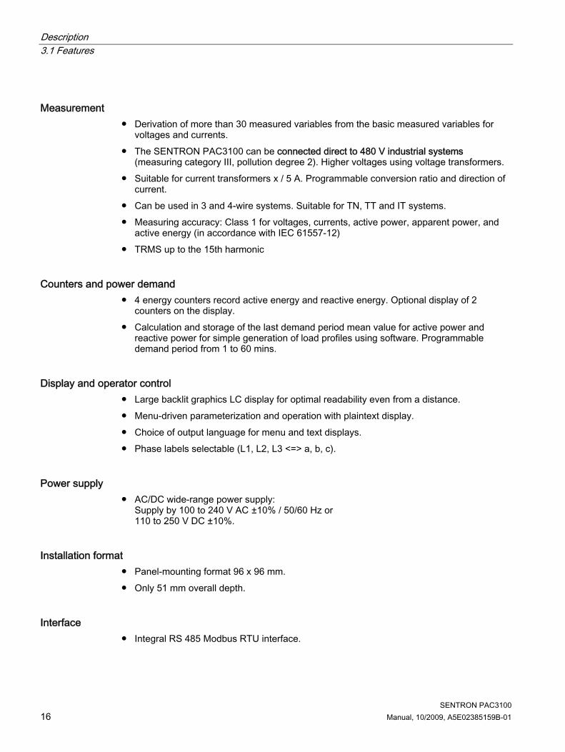
Measurement ● Derivation of more than 30 measured variables from the basic measured variables for
voltages and currents. ● The SENTRON PAC3100 can be connected direct to 480 V industrial systems
(measuring category III, pollution degree 2). Higher voltages using voltage transformers. ● Suitable for current transformers x / 5 A. Programmable conversion ratio and direction of
current. ● Can be used in 3 and 4-wire systems. Suitable for TN, TT and IT systems. ● Measuring accuracy: Class 1 for voltages, currents, active power, apparent power, and
active energy (in accordance with IEC 61557-12) ● TRMS up to the 15th harmonic
Counters and power demand ● 4 energy counters record active energy and reactive energy. Optional display of 2
counters on the display. ● Calculation and storage of the last demand period mean value for active power and
reactive power for simple generation of load profiles using software. Programmable demand period from 1 to 60 mins.
Display and operator control ● Large backlit graphics LC display for optimal readability even from a distance. ● Menu-driven parameterization and operation with plaintext display. ● Choice of output language for menu and text displays. ● Phase labels selectable (L1, L2, L3 <=> a, b, c).
Power supply ● AC/DC wide-range power supply:
Supply by 100 to 240 V AC ±10% / 50/60 Hz or 110 to 250 V DC ±10%.
Installation format ● Panel-mounting format 96 x 96 mm. ● Only 51 mm overall depth.
Interface ● Integral RS 485 Modbus RTU interface.

Description 3.2 Measuring inputs
SENTRON PAC3100 Manual, 10/2009, A5E02385159B-01 17
Inputs and outputs ● 2 digital inputs with internal power supply for status monitoring. ● 2 digital outputs, programmable as energy pulse outputs for active energy pulses or
reactive energy pulses, or as switching outputs for remote control via the RS 485 interface.
Protection Password protection on the device by means of 4-character code.
See also Measured variables (Page 20) Technical data (Page 105)
3.2 Measuring inputs
Current measurement
CAUTION AC current measurement only The device is not suitable for measuring DC current.
SENTRON PAC3100 is designed for: ● Measuring current of 5 A for connecting standard current transformers. Each current
measuring input can take a continuous load of 10 A (max. 300 V). Surge withstand capability is possible for currents up to 100 A and a duration of 1 s.
Voltage measurement
CAUTION AC voltage measurement only The device is not suitable for measuring DC voltage.
SENTRON PAC3100 is designed for: ● Direct measurement on the system or using voltage transformers. The measuring voltage
inputs of the device measure direct via protective impedances. External voltage transformers are required to measure higher voltages than the permissible rated input voltages.
● Measuring voltage up to 277 V / 480 V. The device is designed for measuring input voltages up to 277 V to the neutral conductor and 480 V to the external conductor.

Description 3.2 Measuring inputs
SENTRON PAC3100 18 Manual, 10/2009, A5E02385159B-01
Connection types Two connection types have been provided for connecting three-wire or four-wire systems with unbalanced load.
Table 3- 2 Available connection types
Short code Connection type 3P4W 3 phases, 4 conductors, unbalanced load 3P3W 3 phases, 3 conductors, unbalanced load
The input circuit of the device must correspond to one of the connection types listed. Select the suitable connection type for the purpose. You can find connection examples in the chapter "Connection".
CAUTION The wrong system connection can destroy the device Before connecting SENTRON PAC3100, you must ensure that the local power supply conditions agree with the specifications on the type plate.
The short code of the connection type must be entered in the device settings at startup. You can find the instructions for parameterizing the connection type in the chapter "Commissioning".
Display of the measured variables depending on the connection type The total set of representable measured variables is restricted by the method of connecting the device. A measured value that cannot be indicated because of the connection method is shown on the display by means of a broken line "----".
Figure 3-1 Display of the measured voltage in the case of connection type 3P4W
Figure 3-2 Display of the measuring voltage in the case of connection type 3P3W
The table below shows which measured values can be represented depending on the connection type.

Description 3.2 Measuring inputs
SENTRON PAC3100 Manual, 10/2009, A5E02385159B-01 19
Table 3- 3 Display of the measured variables depending on the connection type
Connection typeMeasured variable
3P4W 3P3W
Voltage a-n ✓ Voltage b-n ✓ Voltage c-n ✓ Voltage a-b ✓ ✓ Voltage b-c ✓ ✓ Voltage c-a ✓ ✓ Current a ✓ ✓ Current b ✓ ✓ Current c ✓ ✓ Neutral current ✓ Apparent power a ✓ Apparent power b ✓ Apparent power c ✓ Active power a ✓ Active power b ✓ Active power c ✓ Reactive power a (VAR1) ✓ Reactive power b (VAR1) ✓ Reactive power c (VAR1) ✓ Total apparent power over all phases ✓ ✓ Total active power over all phases ✓ ✓ Total reactive power VAR1 over all phases ✓ ✓ Total power factor ✓ ✓ Line frequency ✓ ✓ Active energy ✓ ✓ Reactive energy ✓ ✓ Cumulated active power ✓ ✓ Cumulated reactive power ✓ ✓
Overload display Voltage or current overload are indicated on the display:
Figure 3-3 Indicating overload on the display

Description 3.3 Measured variables
SENTRON PAC3100 20 Manual, 10/2009, A5E02385159B-01
The display shows the message "... OUT OF RANGE". The message can be confirmed and hidden with function key <F4>.
Figure 3-4 Display of the measurable maximum value at overload
The character ">" and the measurable maximum value (physical measuring range multiplied by scaling) are displayed instead of the measured values for affected phases. The symbol in the header indicates overload. The symbol can be seen in all measured value displays.
Current direction The current direction can be changed on the device for all phases individually. It is not necessary to change the terminal connections of the current transformers in the event of connection errors.
See also Connection examples (Page 45) Setting the connection type (Page 55) Connection (Page 39) Applying the measuring voltage (Page 61) Applying the measuring current (Page 61)
3.3 Measured variables
Measured variables – overview The table below lists all measured variables that the device records or derives from basic variables.
Table 3- 4 Measured variables
Measured variable Abbreviation Instantaneous value Min Max Mean value Total value Unit Voltage ph-n Va-n / Vb-n / Vc-n ✓ ✓ ✓ [V] Voltage ph-ph Va-b / Vb-c / Vc-a ✓ ✓ ✓ [V] Current Ia / Ib / Ic ✓ ✓ ✓ [A] Neutral current IN ✓ ✓ ✓ [A] Apparent power per phase VAa / VAb / VAc ✓ ✓ ✓ [VA]

Description 3.4 Power demands and counters
SENTRON PAC3100 Manual, 10/2009, A5E02385159B-01 21
Measured variable Abbreviation Instantaneous value Min Max Mean value Total value Unit Active power per phase import/export
Wa / Wb / Wc ✓ ✓ ✓ [W]
Reactive power (VAR1) per phase positive / negative
VAR1 a / VAR1 b / VAR1 c
✓ ✓ ✓ [VAR]
Total apparent power over all phases
VA ✓ ✓ ✓ [VA]
Total active power over all phases import / export
P ✓ ✓ ✓ ✓1) [W]
Total reactive power VAR1 over all phases positive / negative
Q1 ✓ ✓ ✓ ✓1) [VAR]
Total power factor PF ✓ ✓ ✓ Line frequency f ✓ ✓ ✓ [Hz] Active energy import/export/balance
Ea ✓ [Wh]
Reactive energy import/export/balance
Er ✓ [VARh]
1) Power demand of the last completed period for import and export, as well as minimum and maximum instantaneous value. Can only be called via RS 485 interface. See the chapter "Power demand".
See also Measured variables (Page 119) Power demands and counters (Page 21)
3.4 Power demands and counters
3.4.1 Acquisition of power demand
Values that can be read out SENTRON PAC3100 supplies the power demand of the last completed measuring period: ● Mean values for active power and reactive power, separated in each case for import and
export ● Minimum and maximum active power and reactive power ● Length of the demand period in seconds. The period may be shorter for reasons of
external synchronization. ● Time in seconds since the last synchronization or since completion of the last period.
Example: Period length and length of the demand period Period length: 15 minutes; time of day: 13:03; time in seconds: 180 s. The following can be calculated from this: The last demand period ended at 13:00. The active demand period will end at 13:15 or in 12 minutes.

Description 3.4 Power demands and counters
SENTRON PAC3100 22 Manual, 10/2009, A5E02385159B-01
Availability
Note The power demand of the last measuring period can only be fetched during the current measuring period.
Note The power demand can only be read out via the RS 485 interface. The values are not shown on the display.
You can find more information on accessing the data via MODBUS in the Appendix.
Adjustable parameters ● Time interval in minutes: 1 to 60 min adjustable, default 15 min ● Synchronization via RS 485 interface
See also Modbus RTU (Page 125)
3.4.2 Energy counters
Energy counters SENTRON PAC3100 has energy counters for counting ● Active energy import ● Active energy export ● Reactive energy import ● Reactive energy export The device also calculates the energy balance ● Active energy balance ● Reactive energy balance The energy balance is calculated from: Import minus export.
Availability Two of the 6 variables can be represented on the display and read out via the interface. The selection can be made when parameterizing the device.

Description 3.5 Digital inputs and outputs
SENTRON PAC3100 Manual, 10/2009, A5E02385159B-01 23
3.4.3 Behavior in the case of power failure and power restore After a power failure, the device starts back at zero with the calculation of the power demand of the total active power and total reactive power. Counter statuses and maximum/minimum values are written from the volatile to the non-volatile memory at the following intervals: Counter values Every 5 mins. Maximum/minimum values Every 5 secs., if available
3.5 Digital inputs and outputs The SENTRON PAC3100 has: ● 2 digital inputs ● 2 digital outputs
3.5.1 Digital inputs
Function Both digital inputs have the following function: ● Status monitoring: Capturing statuses of connected signal encoders
(1) Internal power supply (2) Optional additional voltage power supply, max. 30 V, typically 24 V (3) Input electronics
Figure 3-5 Block diagram: Digital inputs

Description 3.5 Digital inputs and outputs
SENTRON PAC3100 24 Manual, 10/2009, A5E02385159B-01
Wiring Both digital inputs have an internal power supply. They can be operated optionally with or without an external power supply. Switch with internal power supply Internal power supply on terminal DIC.
DIC DI0DI1 DOC DO0DO1 (1) Functional ground terminal
Figure 3-6 Digital inputs with switch and internal power supply on terminal DIC
Switch with external power supply In addition to the internal voltage on terminal DIC, and external voltage up to 30 V (typically 24 V) can be applied to terminal DIC.
DIC DI0DI1 DOC DO0DO1 (1) Functional ground terminal (2) External voltage
Figure 3-7 Digital inputs with switch, internal power supply, and additional external power supply on terminal DIC
3.5.2 Digital outputs
Functions The following functions can be assigned to both digital outputs: ● Energy pulse output, programmable for active or reactive energy ● Switching output for remote control via the RS 485 interface

Description 3.5 Digital inputs and outputs
SENTRON PAC3100 Manual, 10/2009, A5E02385159B-01 25
Energy pulse output The digital output supplies a number of pulses proportional to one of the following energies: ● Active energy import ● Active energy export ● Reactive energy import ● Reactive energy export
Figure 3-8 Energy pulse output
Remote control via the RS 485 interface The integral RS 485 interface enables remote control of the digital outputs. The Modbus function codes are listed in the Appendix.
Wiring Both digital outputs are passive and implemented exclusively as switches. Implementation of the pulse function corresponds to the IEC 62053-31 standard. Pulse length, turn-off time
(1) Pulse length (2) Turn-off time
Figure 3-9 Pulse length and turn-off time
● Pulse length: Time for which the signal at the digital output is "high". The minimum pulse length is 30 ms and the maximum 500 ms.
● Turn-off time: Time for which the signal at the digital output is "low". The turn-off time depends on the measured energy, for example, and can be days or months.
● Minimum turn-off time: The minimum turn-off time corresponds to the programmed pulse length. 30 ms is the absolute minimum.

Description 3.6 RS 485 interface
SENTRON PAC3100 26 Manual, 10/2009, A5E02385159B-01
See also Modbus RTU (Page 125)
3.6 RS 485 interface
RS 485 interface for Modbus RTU communication The SENTRON PAC3100 is equipped with an RS 485 interface for Modbus RTU communication.
Application This interface permits: ● Reading out the measured values ● Reading and writing the device settings ● Device firmware updates ● Update of the languages available on the device The Modbus function codes are listed in the Appendix.
Function The device operates as a Modbus slave.
Conditions for operation To use the interface, the device must be parameterized in accordance with the existing Modbus infrastructure. The communication parameters can be set on the device and via the Modbus RTU interface.
Default communication settings In the as-delivered state, the following default values are set:
Table 3- 5 Default Modbus RTU communication settings
Setting Default value Address 126 Baud rate 19200 Data format 8N2 Response time 0 (automatic)

Description 3.7 Slots on the rear of the device
SENTRON PAC3100 Manual, 10/2009, A5E02385159B-01 27
Response time delay The response time of the PAC3100 may have to be delayed to enable its operation as a slave device with devices from other manufacturers on the bus. The PAC3100 can automatically calculate the response time to suit the baud rate. This automatic calculation is set at the factory. The delay time is individually adjustable between 1 and 255 milliseconds.
Polarization Polarization of the RS 485 data lines must be implemented at another point on the bus. The PAC3100 does not contain polarization resistors.
Status LED Two LEDs signal status information:
Table 3- 6 Meaning of the LED signals
Color State Description Green and yellow Off No activity on the bus. Green Flashing Other devices are communicating on the bus. Yellow Flashing The SENTRON PAC3100 is sending data.
See also Connecting to the RS 485 bus (Page 48) Modbus RTU (Page 125)
3.7 Slots on the rear of the device

Description 3.7 Slots on the rear of the device
SENTRON PAC3100 28 Manual, 10/2009, A5E02385159B-01
Slot on the rear of the device
CAUTION The device can be destroyed if objects are inserted Do not insert any objects into the housing slots on the rear of the device.
Figure 3-10 Non-usable housing openings

SENTRON PAC3100 Manual, 10/2009, A5E02385159B-01 29
Operation planning 4Mounting location
The SENTRON PAC3100 device is intended for installation in permanently installed switching panels within closed rooms. Conductive panels and doors on control cabinets must be grounded. The doors of the control cabinet must be connected to the control cabinet using a grounding cable.
Mounting position The device must be installed vertically.
Figure 4-1 Mounting position
The preferred direction of viewing is from below at an angle.
Installation space and ventilation Sufficient clearance must be maintained between the device and neighboring components in order to comply with the permissible operating temperature. You can find dimension specifications in the "Dimensional drawings" chapter. Plan additional space for: ● Ventilation ● Wiring ● RS 485 terminal block and cable infeed on the top of the device
CAUTION Ensure ventilation Please ensure that the ventilation slots of the housing are not obstructed. The wiring, cable feed or other components must not obstruct ventilation.

Operation planning
SENTRON PAC3100 30 Manual, 10/2009, A5E02385159B-01
Environmental conditions Use the SENTRON PAC3100 device only where environmental conditions permit its operation:
Table 4- 1 Environmental conditions
Temperature range Operating temperature - 10 °C through + 55 °C Storage and transport temperature - 25 °C through + 70 °C Relative humidity 95% at 25°C without condensation
(normal conditions) Installation altitude above sea level max. 2000 m Degree of pollution 2 Degree of protection according to IEC 60529 Device front IP65
Type 5 enclosure acc. to UL50 Device rear IP20
Circuit breaker A suitable circuit breaker must be connected upstream of SENTRON PAC3100 in order to permit disconnection of the device from the power supply! ● The circuit breaker must be mounted close to the device and be easily accessible to the
user. ● The circuit breaker must be marked as the circuit breaker for the device.
Temperature compensation To avoid condensation, the device must be stored at the operating location for at least 2 hours before power is connected.
See also Dimensional drawings (Page 115)

SENTRON PAC3100 Manual, 10/2009, A5E02385159B-01 31
Mounting 55.1 Unpacking
Observe the ESD Guidelines. Open the packaging carefully. Do not use excessive force.
Check the packaging Carry out the following checks after receipt of the device and before installation: ● Ensure the packaging is undamaged ● Make sure that the contents of the package are complete ● Check the device for external damage Please contact your Siemens sales partner in the following cases: ● The packaging is damaged ● The contents of the package are not complete ● The device is damaged
WARNING
Damaged devices may result in death, serious injury, or property damage Do not install or start up damaged devices.
Storage Store the SENTRON PAC3100 in dry conditions.
NOTICE Avoid condensation Sudden fluctuations in temperature can lead to condensation. Condensation can affect the function of the device. Store the device in the operating room for at least 2 hours before commencing installation.

Mounting 5.2 Mounting on the switching panel
SENTRON PAC3100 32 Manual, 10/2009, A5E02385159B-01
5.2 Mounting on the switching panel
5.2.1 Tools You require the following tools for installation: ● Cutting tool for the panel cutout ● Screwdriver PH2 cal. ISO 6789
Additional installation tools ● Cable clamp for strain relief on the RS 485 connection.
5.2.2 Mounting dimensions
Mounting and clearance dimensions You can find information on the cutout dimensions, frame dimensions and clearances in the Chapter "Dimensional drawings".
See also Dimensional drawings (Page 115)
5.2.3 Installation steps Proceed as follows to install the SENTRON PAC3100 in the switching panel:
Procedure 1. Cut a hole in the panel measuring 92.0+0.8 x 92.0+0.8 mm2 (if not already available). 2. Discharge any static from your body. Observe the ESD guidelines in the Appendix.
CAUTION
Electrostatic sensitive devices Discharge your body of any static electricity. Touch the grounded control cabinet, for example, or a metal part that is connected to the building ground (heater, steel support).
3. Insert the device into the cutout from outside (Fig. "Installation cutout A"). 4. Carry out all other installation steps from the inside of the switching panel.

Mounting 5.2 Mounting on the switching panel
SENTRON PAC3100 Manual, 10/2009, A5E02385159B-01 33
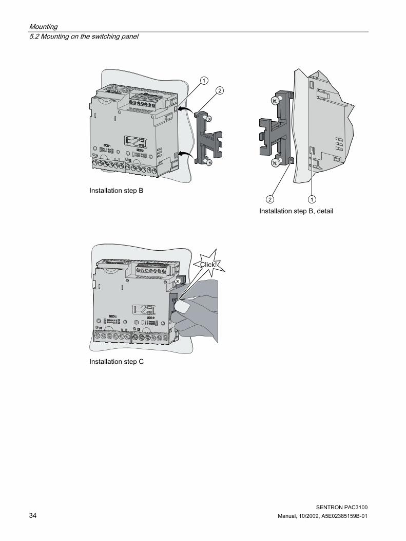
5. Clamp the device to the switching panel with the two brackets provided (Fig. "Installation step B"). To do this, proceed as follows: – Hold the device firmly with one hand – Hang the brackets onto the left and right sides of the housing.
To do so, insert the lugs of the bracket (2) into the slot on the housing (1). – Tighten the locking hook.
To do so, place your index finger and middle finger on the support arms as shown in the Fig. "Installation step C" and engage the locking hook with your thumb. The engage mechanism of both brackets enables the installation engineer to secure the device in the switching panel quickly and without tools. To achieve degree of protection IP65, the four screws in the supports must be additionally tightened.
6. Tighten the 4 screws evenly in the two brackets; tightening torque 0.5 Nm (Fig. "Installation step D"). The front of the switching panel is fully sealed with the standard, integrally extruded seal.
7. When using the RS 485 interface: Ensure strain relief for the connected RS 485 lines. Secure the RS 485 cable to the panel for this purpose. Fix the cable in position as shown in the Fig. "Installation step E" at location (3) using a self-adhesive cable clamp or other suitable small installation accessory.
Installation is complete.
NOTICE Ensure that no tools or other potentially hazardous objects have been left at the installation location.
Installation steps
SENTRON PAC3100
SIEMENS
Installation step A
Mounting 5.2 Mounting on the switching panel
SENTRON PAC3100 34 Manual, 10/2009, A5E02385159B-01
Installation step B
Installation step B, detail
Installation step C

Mounting 5.2 Mounting on the switching panel
SENTRON PAC3100 Manual, 10/2009, A5E02385159B-01 35
Installation step D

Mounting 5.3 Deinstallation
SENTRON PAC3100 36 Manual, 10/2009, A5E02385159B-01
Installation step E – Strain relief of the RS 485 connection
See also ESD guidelines (Page 141)
5.3 Deinstallation
Tools You require the following tools to deinstall the device: ● PH2 screwdriver ● Slotted screwdriver
Mounting 5.3 Deinstallation
SENTRON PAC3100 Manual, 10/2009, A5E02385159B-01 37
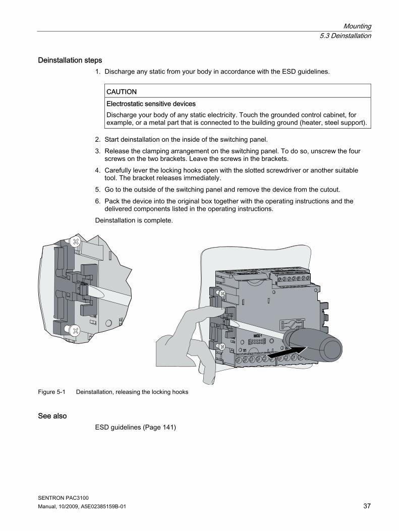
Deinstallation steps 1. Discharge any static from your body in accordance with the ESD guidelines.
CAUTION
Electrostatic sensitive devices Discharge your body of any static electricity. Touch the grounded control cabinet, for example, or a metal part that is connected to the building ground (heater, steel support).
2. Start deinstallation on the inside of the switching panel. 3. Release the clamping arrangement on the switching panel. To do so, unscrew the four
screws on the two brackets. Leave the screws in the brackets. 4. Carefully lever the locking hooks open with the slotted screwdriver or another suitable
tool. The bracket releases immediately. 5. Go to the outside of the switching panel and remove the device from the cutout. 6. Pack the device into the original box together with the operating instructions and the
delivered components listed in the operating instructions. Deinstallation is complete.
Figure 5-1 Deinstallation, releasing the locking hooks
See also ESD guidelines (Page 141)

Mounting 5.3 Deinstallation
SENTRON PAC3100 38 Manual, 10/2009, A5E02385159B-01

SENTRON PAC3100 Manual, 10/2009, A5E02385159B-01 39
Connection 66.1 Safety notes
Instructions
DANGER
Hazardous Voltage Will cause death, serious injury or property damage. Turn off and lock out all power supplying this device before working on this device.
Note The following tasks are partly carried out when hazardous voltage is present. For this reason, they must only be carried out by qualified personnel who are familiar with and follow the safety regulations and cautionary measures. Wear the prescribed protective clothing. Observe the general equipment regulations and safety regulations for working with high-voltage installations (e.g. DIN VDE, NFPA 70E as well as national or international regulations). The limits given in the technical data must not be exceeded even at startup or when testing the device. The secondary connections of intermediate current transducers must be short-circuited at the transducers before the current lines to the device are interrupted. The polarity and phase assignment of the measuring transducer must be tested. Before connecting the device, you must check that the system voltage agrees with the voltage specified on the type plate. Check that all connections are correctly made before startup. Ensure the polarity is correct when connecting a DC supply voltage. Before power is applied to the device for the first time, it must have been located in the operating area for at least two hours in order to reach temperature balance and avoid humidity and condensation. Condensation on the device is not permissible during operation.
Connection 6.2 Connections
SENTRON PAC3100 40 Manual, 10/2009, A5E02385159B-01
Note Qualified Personnel In the context of the safety information in the user documentation, a qualified person is a person who is familiar with assembling, installing, commissioning, and operating the product and who has the relevant qualifications, such as: • Training or instruction/authorization in operating and maintaining devices and systems
according to the safety regulations for electrical circuits and devices. • Is trained in the proper care and use of protective equipment in accordance with
established safety practices. • First aid training.
See also Safety notes (Page 13) Applying the supply voltage (Page 51) Applying the measuring voltage (Page 61) Applying the measuring current (Page 61)
6.2 Connections
DANGER
Hazardous Voltage Will cause death, serious injury or considerable property damage. Observe the safety information on the device and in the operating instructions and the manual.

Connection 6.2 Connections
SENTRON PAC3100 Manual, 10/2009, A5E02385159B-01 41
Connection designations
DIC DI0DI1 DOC DO0DO1
(1) Digital inputs and outputs, functional ground (2) Dummy connections. Cannot be used as slots! (3) Supply voltage L/+, N/- (4) Measuring inputs voltage V1, V2, V3, VN (5) Measuring inputs current IL1, IL2, IL3 (6) RS 485 connector
Figure 6-1 Connection designations, view of the rear and top of the device

Connection 6.2 Connections
SENTRON PAC3100 42 Manual, 10/2009, A5E02385159B-01
Terminal labeling
DIC DI0DI1 DOC DO0DO1
No. Terminal Function (1) IL1 °↑k ̇̇̇k Current Ia, input (2) IL1 l↓ l Current Ia, output (3) IL2 °↑k ̇k Current Ib, input (4) IL2 l↓ l Current Ib, output (5) IL3 °↑k ̇k Current Ic, input (6) IL3 l↓ l Current Ic, output (7) V1 Voltage Va-n (8) V2 Voltage Vb-n (9) V3 Voltage Vc-n (10) VN Neutral conductor (11) L/+ AC: Connection: Conductor (phase-to-neutral voltage)
DC: Connection: + (12) N/- AC: Connection: Neutral conductor
DC: Connection: - (13) Functional ground (14) DIC Digital input (common) (15) DI1 Digital input 1 (16) DI0 Digital input 0 (17) DOC Digital output (common) (18) DO1 Digital output 1 (19) DO0 Digital output 0
Figure 6-2 Terminal labeling

Connection 6.2 Connections
SENTRON PAC3100 Manual, 10/2009, A5E02385159B-01 43
No. Terminal Function (20) Com Common = Ground (21) +/B B signal; D1 (22) -/A A signal; D0
Figure 6-3 Terminal labeling
Grounding Conductive panels and doors on control cabinets must be grounded. The doors of the control cabinet must be connected to the control cabinet using a grounding cable.
Functional ground
DIC DI0DI1 DOC DO0DO1
(13) Functional ground terminal
Figure 6-4 Terminal block with 2 digital inputs and outputs, functional ground
The connection "functional ground" discharges interference affecting the digital inputs and outputs and the RS 485 interface. Connect the functional ground to the equipotential bonding strip in the control cabinet. The maximum cable length for connecting the functional ground is 3 meters.

Connection 6.2 Connections
SENTRON PAC3100 44 Manual, 10/2009, A5E02385159B-01
Supply voltage fuse protection
CAUTION Non-fused supply voltage may lead to device and equipment damage Damage to the device and the equipment may occur. Always protect the device with an IEC approved or UL listed CLASS CC 0.6 A fuse.
If a fusible link is used, a suitable IEC approved or UL listed fuse holder has to be used. In addition, a suitable isolating device shall be connected upstream in order to permit disconnection of the device from the power supply.
Protecting the current measuring inputs
DANGER
Open transformer circuits will result in electric shock and arc flashover Will cause death, serious injury or considerable property damage. Only measure current with external current transformers. Do not use fuses for circuit protection. Do not open the secondary circuit under load. Short circuit the secondary current terminals of the current transformer before removing this device. The safety information for the current transformers used must be followed.
Protecting the voltage measuring inputs
CAUTION Non-fused voltage measuring points may lead to device and equipment damage. Always protect the device with an IEC approved or UL listed 10 A fuse, circuit breaker or supplementary protector. Never short circuit the secondary connections of the voltage transformers.

Connection 6.3 Connecting the cables to the terminals
SENTRON PAC3100 Manual, 10/2009, A5E02385159B-01 45
6.3 Connecting the cables to the terminals
Connecting cables to the screw terminal Tool: PZ2 cal. screwdriver ISO 6789
Figure 6-5 Connecting cables to the screw terminal
6.4 Connection examples Some connection examples are listed below: They show connection in: ● Three-wire or four-wire systems ● with unbalanced load ● With/without voltage transformer ● with current transformer The device can be operated up to the maximum permissible voltage values with or without voltage measuring transformers. It is only possible to measure the current with current transformers. All input or output terminals not required for measuring remain free. In the connection examples, the secondary side of the transformer is grounded at the "l" terminal. It can be grounded at either the "k" or the "l" terminal. The grounding has no impact on the measurement. The wiring method must be made known to the device in the device settings. The connection types given below refer to the device parameterization.

Connection 6.4 Connection examples
SENTRON PAC3100 46 Manual, 10/2009, A5E02385159B-01
Connection examples (1) Three-phase measuring, four conductors, unbalanced load, without voltage transformers, with three current transformers Connection type 3P4W
* Fuses must be provided by the customer. ** Connection of supply voltage
Figure 6-6 Connection type 3P4W, without voltage transformer, with three current transformers
(2) Three-phase measuring, four conductors, unbalanced load, with voltage transformers, with three current transformers Connection type 3P4W
* Fuses must be provided by the customer. ** Connection of supply voltage
Figure 6-7 Connection type 3P4W, with voltage transformer, with three current transformers

Connection 6.4 Connection examples
SENTRON PAC3100 Manual, 10/2009, A5E02385159B-01 47
(3) Three-phase measuring, three conductors, unbalanced load, without voltage transformers, with three current transformers Connection type 3P3W
* Fuses must be provided by the customer. ** Connection of supply voltage
Figure 6-8 Connection type 3P3W, without voltage transformer, with three current transformers
(4) Three-phase measuring, three conductors, unbalanced load, with voltage transformers, with three current transformers Connection type 3P3W
* Fuses must be provided by the customer. ** Connection of supply voltage
Figure 6-9 Connection type 3P3W, with voltage transformer, with three current transformers

Connection 6.5 Connecting to the RS 485 bus
SENTRON PAC3100 48 Manual, 10/2009, A5E02385159B-01
(5) Three-phase measuring, four conductors, unbalanced load, with voltage transformers, with three current transformers Connection type 3P3W
* Fuses must be provided by the customer. ** Connection of supply voltage
Figure 6-10 Connection type 3P3W, with voltage transformer, with three current transformers
See also Measuring inputs (Page 17)
6.5 Connecting to the RS 485 bus
Procedure Connect the SENTRON PAC3100 to the RS 485 bus via the integral interface. Please pay attention here to the general topology of the two-wire line. 1. Connect the RS 485 cables to the screw terminals of the terminal block. 2. Connect the cable shield at one end with protective ground PE. 3. Connect the signal Common with protective ground. 4. Ensure a bus terminating resistance is set at the first and last communication node.

Connection 6.5 Connecting to the RS 485 bus
SENTRON PAC3100 Manual, 10/2009, A5E02385159B-01 49
RS 485 terminal block
COM Common = Ground +/B B signal; D1 -/A A signal; D0
Figure 6-11 RS 485 terminal block
Block diagram
TER Bus termination resistor (termination) PU Pull-up resistor PD Pull-down resistor (1) Grounding of the cable shielding (2) Grounding of the common line, preferably only at one point for the whole bus
Figure 6-12 Block diagram: General RS 485 topology
Connection 6.5 Connecting to the RS 485 bus
SENTRON PAC3100 50 Manual, 10/2009, A5E02385159B-01
Grounding of the cable shielding The serial Modbus data line must be shielded. The shielding must be connected to protective ground at one end of the cable. The shielding is grounded at one end only.
Grounding of the common line The common line must be applied direct to protective ground, preferably at only one point for the whole bus.
Polarization The PAC3100 does not support polarization of the RS 485 data lines. Polarization must be implemented at another point on the bus. The master device usually performs the polarization. We recommend polarization with supply of 5 V DC, pull-up resistor with 560 Ω, pull-down resistor with 560 Ω.
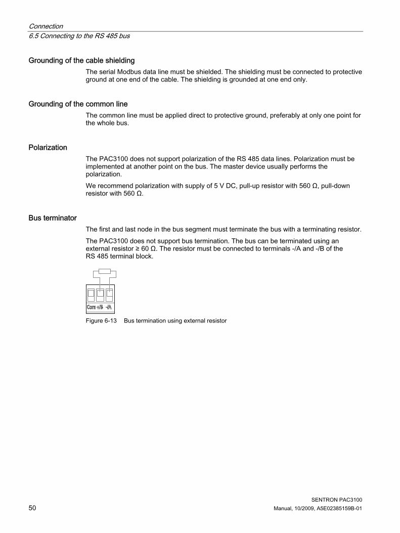
Bus terminator The first and last node in the bus segment must terminate the bus with a terminating resistor. The PAC3100 does not support bus termination. The bus can be terminated using an external resistor ≥ 60 Ω. The resistor must be connected to terminals -/A and -/B of the RS 485 terminal block.
Figure 6-13 Bus termination using external resistor

SENTRON PAC3100 Manual, 10/2009, A5E02385159B-01 51
Commissioning 77.1 Overview
Prerequisites 1. The device has been installed. 2. The device has been connected in accordance with the possible connection methods. The device must be connected to the bus for communication via the RS 485 interface.
Steps for starting up the device 1. Apply the supply voltage 2. Parameterize the device 3. Apply the measuring voltage 4. Apply the measuring current 5. Check the displayed measured values
NOTICE Check the connections Incorrect connection can result in malfunctions and failure of the device. Before starting up the SENTRON PAC3100, check that all connections are correct.
7.2 Applying the supply voltage A supply voltage is required to operate the device. Please consult the technical data or the type plate for the type and level of the possible supply voltage.
WARNING
Do not apply voltage in excess of the rated voltage limit Failure to do so may result in death, serious injury, or property damage The limits given in the technical data and on the type plate must not be exceeded even at startup or when testing the device.

Commissioning 7.2 Applying the supply voltage
SENTRON PAC3100 52 Manual, 10/2009, A5E02385159B-01
Supply voltage fuse protection
CAUTION Non-fused supply voltage may lead to device and equipment damage Always protect the device with an IEC approved or UL listed CLASS CC 0.6 A fuse. If a fusible link is used, a suitable IEC approved or UL listed fuse holder has to be used. In addition, a suitable isolating device shall be connected upstream in order to permit disconnection of the device from the power supply. Do not use voltage transformers as a power supply.
Procedure Connect the supply voltage to terminals L/+ and N/-.
Table 7- 1 Connection of supply voltage
Terminal marking Connection L/+ AC: Connection: Conductor (phase-to-neutral voltage)
DC: Connection: + N/- AC: Connection: Neutral conductor
DC: Connection: -
See also Safety notes (Page 13) Safety notes (Page 39) Applying the measuring voltage (Page 61) Technical data (Page 105)

Commissioning 7.3 Parameterizing the device
SENTRON PAC3100 Manual, 10/2009, A5E02385159B-01 53
7.3 Parameterizing the device
Procedure To start up the device, you must specify the operating parameters listed below in the device settings: ● Connection type ● Voltage
– Direct measurement on the system or using voltage transformers – Measuring input voltage in the case of direct measurement on the system – Primary and secondary voltage when measuring using voltage transformers
● Current – Primary current
When using the RS 485 interface: ● Communication settings The following settings are also useful: ● Language ● Phase labels ● Password protection
See also Password management (Page 95)
7.3.1 Setting the language First, set the language in which the display text is to appear. The available languages are displayed: ● at initial startup, ● after resetting to factory settings English is the default language.
Figure 7-1 Language selection
Select the desired language by pressing <F2> or <F3> . Apply the desired language with <F4> .

Commissioning 7.3 Parameterizing the device
SENTRON PAC3100 54 Manual, 10/2009, A5E02385159B-01
Changing the language 1. Exit the measured value display and call the "MAIN MENU":
<F4> 2. In the main menu, go to the "SETTINGS" entry:
<F2> or <F3> 3. Call the "SETTINGS" entry:
<F4> 4. In the "SETTINGS" menu, go to the "LANGUAGE/REGIONAL" entry:
<F2> or <F3>
Figure 7-2 "SETTINGS" menu
5. Call the "LANGUAGE/REGIONAL" entry: <F4> The display shows the currently valid settings.
6. Open edit mode of the "LANGUAGE" device setting: <F4>
Figure 7-3 "LANGUAGE" edit mode
7. Scroll through the possible values with: <F2>
8. Accept the desired language with: <F4> The language is permanently saved and becomes effective immediately. The display returns to display mode.
9. Return to one of the selection menus or to the measured values display: <F1>

Commissioning 7.3 Parameterizing the device
SENTRON PAC3100 Manual, 10/2009, A5E02385159B-01 55
7.3.2 Voltage input
7.3.2.1 Setting the connection type Inform the device of the connection type executed. To do so, enter the short code for the connection type in the device settings.
Note Connection type The connection type executed must agree with the connection type entered in the device.
Table 7- 2 Available connection types
Short code Connection type 3P4W 3 phases, 4 conductors, unbalanced load 3P3W 3 phases, 3 conductors, unbalanced load
You can find further information on the possible connection types, and on how the measured value representation depends on the connection type, in the "Description" chapter.
Procedure 1. Exit the measured value display and call the "MAIN MENU":
<F4> 2. In the main menu, go to the "SETTINGS" entry:
<F2> or <F3> 3. Call the "SETTINGS" entry:
<F4> 4. In the "SETTINGS" menu, go to the "BASIC PARAMETERS" entry:
<F2> or <F3> 5. Call the "BASIC PARAMETERS" entry:
<F4> 6. In the "BASIC PARAMETERS" menu, call the "VOLTAGE INPUTS" entry:
<F4> The display shows the currently valid settings.
Figure 7-4 "CONNECTION TYPE" device setting
7. Open edit mode of the "CONNECTION TYPE" device setting: <F4>

Commissioning 7.3 Parameterizing the device
SENTRON PAC3100 56 Manual, 10/2009, A5E02385159B-01
8. Scroll through the possible values with: <F2>
9. Accept the desired connection type: <F4> The connection type is permanently saved and becomes effective immediately. The display returns to display mode.
10. Return to one of the selection menus or to the measured values display: <F1>
See also Measuring inputs (Page 17)
7.3.2.2 Measurement using voltage transformers The factory setting is measurement direct on the system. At initial startup, the following steps must be carried out if you want to measure using voltage transformers.
Procedure 1. In the "SETTINGS" menu, call the "BASIC PARAMETERS" entry. 2. In the "BASIC PARAMETERS" menu, open the "VOLTAGE INPUTS" entry:
<F4> The display shows the currently valid settings.
3. Go to the "USE PTs?" device setting: <F2> or <F3>
Figure 7-5 "USE PTs?" device setting
4. Switch converter measurement on/off: <F4>
On: Measurement using voltage transformers. Off: Measurement direct on the low-voltage system.
The device setting is saved permanently and becomes effective immediately. The display remains in display mode.
5. Return to one of the selection menus or to the measured values display: <F1>
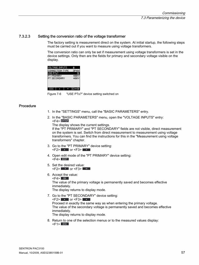
Commissioning 7.3 Parameterizing the device
SENTRON PAC3100 Manual, 10/2009, A5E02385159B-01 57
7.3.2.3 Setting the conversion ratio of the voltage transformer The factory setting is measurement direct on the system. At initial startup, the following steps must be carried out if you want to measure using voltage transformers. The conversion ratio can only be set if measurement using voltage transformers is set in the device settings. Only then are the fields for primary and secondary voltage visible on the display.
Figure 7-6 "USE PTs?" device setting switched on
Procedure 1. In the "SETTINGS" menu, call the "BASIC PARAMETERS" entry. 2. In the "BASIC PARAMETERS" menu, open the "VOLTAGE INPUTS" entry:
<F4> The display shows the current settings. If the "PT PRIMARY" and "PT SECONDARY" fields are not visible, direct measurement on the system is set. Switch from direct measurement to measurement using voltage transformers. You can find the instructions for this in the "Measurement using voltage transformers" chapter.
3. Go to the "PT PRIMARY" device setting: <F2> or <F3>
4. Open edit mode of the "PT PRIMARY" device setting: <F4>
5. Set the desired value: <F2> or <F3>
6. Accept the value: <F4> The value of the primary voltage is permanently saved and becomes effective immediately. The display returns to display mode.
7. Go to the "PT SECONDARY" device setting: <F2> or <F3> Proceed in exactly the same way as when entering the primary voltage. The value of the secondary voltage is permanently saved and becomes effective immediately. The display returns to display mode.
8. Return to one of the selection menus or to the measured values display: <F1>

Commissioning 7.3 Parameterizing the device
SENTRON PAC3100 58 Manual, 10/2009, A5E02385159B-01
Example: You want to measure using voltage transformers for 1000 V/100 V on a 690 V system. For this purpose, enter: 1. USE PTs?: On: 2. PT PRIMARY: 690 V 3. PT SECONDARY: 69 V
Figure 7-7 "VOLTAGE INPUTS" device setting
See also Measurement using voltage transformers (Page 56)
7.3.2.4 Setting the voltage input The factory setting for the measuring reference voltage Vph-ph is 400 V. At initial startup, the following steps must be carried out if the available measuring voltage Vph-ph deviates from this.
Procedure 1. In the "SETTINGS" menu, call the "BASIC PARAMETERS" entry. 2. In the "BASIC PARAMETERS" menu, open the "VOLTAGE INPUTS" entry:
<F4> The display shows the currently valid settings.
3. Go to the "VOLTAGE INPUTS" device setting: <F2> or <F3>
Figure 7-8 "VOLTAGE INPUTS" device setting
4. Open edit mode of the "VOLTAGE INPUTS" device setting: <F4>
5. Set the desired value: <F2> and <F3>
6. Accept the value: <F4>
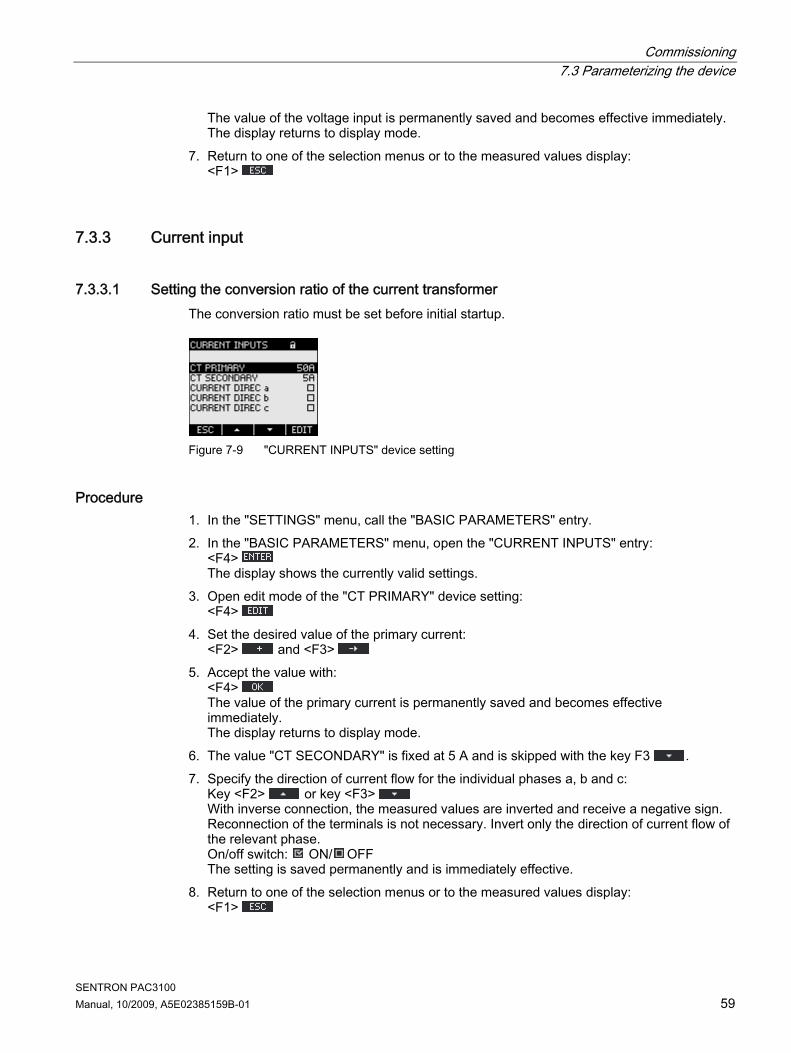
Commissioning 7.3 Parameterizing the device
SENTRON PAC3100 Manual, 10/2009, A5E02385159B-01 59
The value of the voltage input is permanently saved and becomes effective immediately. The display returns to display mode.
7. Return to one of the selection menus or to the measured values display: <F1>
7.3.3 Current input
7.3.3.1 Setting the conversion ratio of the current transformer The conversion ratio must be set before initial startup.
Figure 7-9 "CURRENT INPUTS" device setting
Procedure 1. In the "SETTINGS" menu, call the "BASIC PARAMETERS" entry. 2. In the "BASIC PARAMETERS" menu, open the "CURRENT INPUTS" entry:
<F4> The display shows the currently valid settings.
3. Open edit mode of the "CT PRIMARY" device setting: <F4>
4. Set the desired value of the primary current: <F2> and <F3>
5. Accept the value with: <F4> The value of the primary current is permanently saved and becomes effective immediately. The display returns to display mode.
6. The value "CT SECONDARY" is fixed at 5 A and is skipped with the key F3 . 7. Specify the direction of current flow for the individual phases a, b and c:
Key <F2> or key <F3> With inverse connection, the measured values are inverted and receive a negative sign. Reconnection of the terminals is not necessary. Invert only the direction of current flow of the relevant phase. On/off switch: ON/ OFF The setting is saved permanently and is immediately effective.
8. Return to one of the selection menus or to the measured values display: <F1>

Commissioning 7.3 Parameterizing the device
SENTRON PAC3100 60 Manual, 10/2009, A5E02385159B-01
Example You want to measure the current using current transformers for 5000 A/5 A. For this purpose, enter: 1. CT PRIMARY: 5000A 2. CT SECONDARY: 5A
Figure 7-10 Device setting "CURRENT INPUTS - CT PRIMARY?"
7.3.4 RS 485 interface The Modbus communication parameters have to be set on the device for initial startup of the integral RS 485 interface.
Procedure 1. In the "SETTINGS" menu, call the "COMMUNICATION" entry:
<F4> The display shows the currently valid settings.
2. Go to the communication settings that you want to change: <F2> or <F3>
3. Open edit mode of the communication setting: <F4>
4. Set the desired value: <F2> and <F3>
5. Accept the value with: <F4> The value is permanently saved and becomes effective immediately. The display returns to display mode.
6. Change other settings. 7. Return to one of the selection menus or to the measured values display:
<F1>

Commissioning 7.4 Applying the measuring voltage
SENTRON PAC3100 Manual, 10/2009, A5E02385159B-01 61
7.4 Applying the measuring voltage The SENTRON PAC3100 is designed for measuring in systems with rated AC voltages up to ● 277 V phase-to-neutral and ● 480 V phase-to-phase.
CAUTION Observe limit values The limits given in the technical data or on the type plate must not be exceeded even at startup or when testing the device. Measurement of DC voltage is not possible. External voltage transformers are required to measure higher voltages than the permissible rated input voltages.
See also Measuring inputs (Page 17) Safety notes (Page 13) Safety notes (Page 39) Applying the supply voltage (Page 51)
7.5 Applying the measuring current The device is designed for connection of current transformers with secondary currents of 5 A. It is only possible to measure alternating currents. The current measuring inputs can each be loaded with 10 A (max. 300 V) continuously or with 100 A for 1 second.
DANGER
Open transformer circuits will result in electric shock and arc flashover Will cause death, serious injury or considerable property damage. Only measure current with external current transformers. Do not use fuses for circuit protection. Do not open the secondary circuit under load. Short circuit the secondary current terminals of the current transformer before removing this device. The safety information for the current transformers used must be followed.

Commissioning 7.6 Checking the displayed measured values
SENTRON PAC3100 62 Manual, 10/2009, A5E02385159B-01
CAUTION Do not measure direct currents Direct currents cannot be measured with the device.
Direction of current flow Please take account of the direction of current flow when connecting the current measuring inputs. With inverse connection, the measured values are inverted and receive a negative sign. To correct the direction of current flow, it is not necessary to reverse the input terminals. Instead, change the interpretation of the direction in the device settings. You can find more information in the chapter "Basic parameters", "CURRENT DIREC" fields.
See also Measuring inputs (Page 17) Safety notes (Page 13) Safety notes (Page 39) Basic parameters (Page 85)
7.6 Checking the displayed measured values
Correct connection type With the help of the table "Displaying the measured variables depending on the connection type", check whether the measured variables are displayed in accordance with the connection type executed. Any deviation indicates a wiring fault or configuration error.
See also Measuring inputs (Page 17)

SENTRON PAC3100 Manual, 10/2009, A5E02385159B-01 63
Operator control 88.1 Device interface
8.1.1 Displays and operator controls
Displays and operator controls The front of the SENTRON PAC3100 has the following displays and operator controls.
(1) Display of the measured values, device settings, selection menus (2) Display title (3) Labeling of the function keys (4) Surfaces of the function keys
Figure 8-1 Device interface
Display: Display - Display title - Key labeling The display is structured as follows: ● Display area - represents the current measured values, device settings and selection
menus. ● Header area - specifies the information visible in the display area. ● Footer area - specifies the functions assigned to the function keys.

Operator control 8.1 Device interface
SENTRON PAC3100 64 Manual, 10/2009, A5E02385159B-01
Function keys: Key labeling - Key surfaces The four function keys F1 to F4 enable operator input to the device: ● Navigation in the menus ● Selection of the measured value displays ● Display and editing of the device settings The keys have multiple assignments. Function assignments and key labeling change according to the context of operator input. The designation of the current key function can be seen above the key number in the footer area of the display. A short press on the key triggers the function once. Holding the key down for longer switches on the autorepeat function after approximately 1 second. The function of the key is triggered repeatedly while the key is held down. Autorepeat is useful, for example, for fast incrementing of values when parameterizing the device.
Organization of information The display organizes the viewable information as follows: Measured variables ● Display of the measured variables
The display shows the measured values of the currently selected measured variable. Menus ● "MAIN MENU"
The display lists the viewable measured variables. ● "SETTINGS" menu
The display lists the device settings. The "SETTINGS" menu is a submenu of the "MAIN MENU". The "SETTINGS" menu contains further submenus.
Device settings ● Display of the device settings
The display shows the values of the currently effective device settings. ● Edit mode of the device settings
The display enables editing of the device settings.
Navigation through the views Navigation through the measured variables, menus and device settings is assigned throughout to the function keys F1 and F4: ● F1 : Cancels the last operator action. Returns from display of the device settings to
display of the menu. ● F4 : Calls the main menu. ● F4 : Calls the selected menu entry. ● F4 : Opens edit mode of the device setting. The figure below shows the navigation paths. The display of the measured variables is the starting point and end point of the navigation. Repeated pressing of F1 returns you to the display of the measured variables.
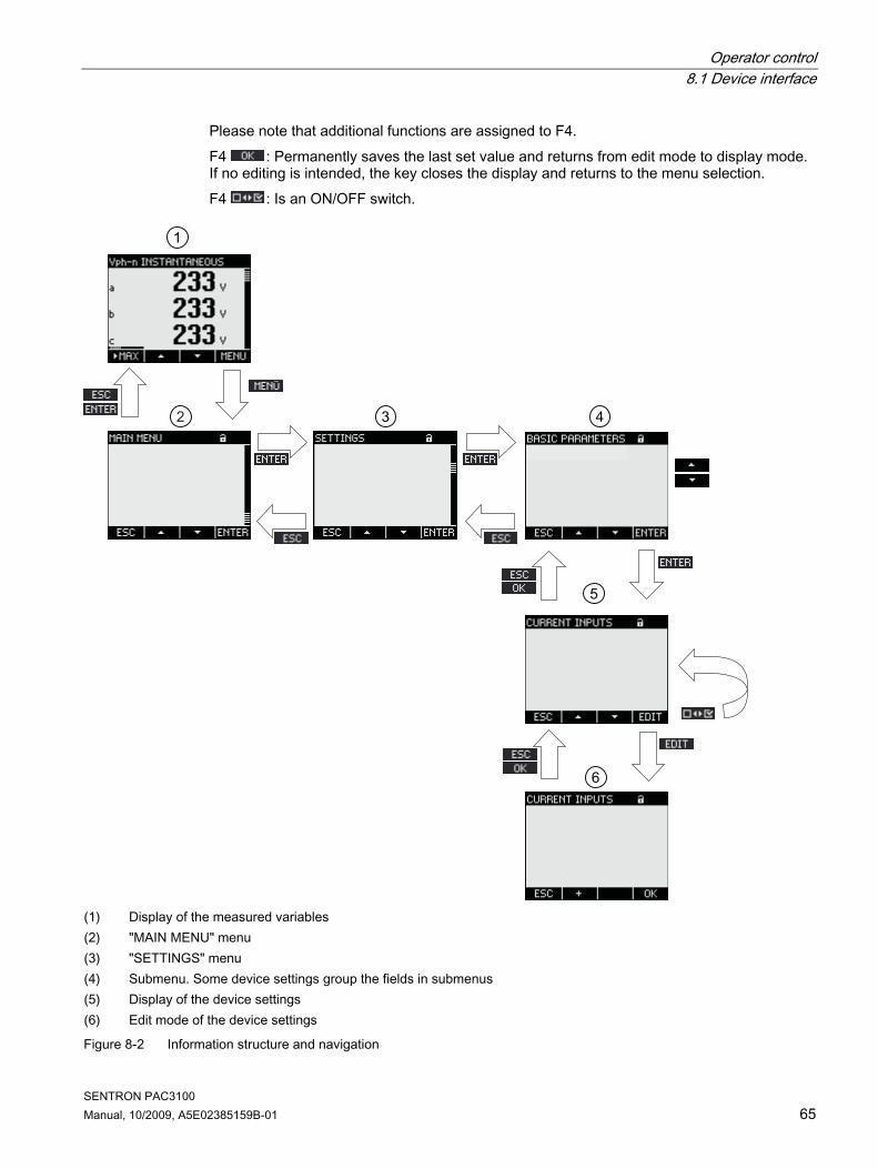
Operator control 8.1 Device interface
SENTRON PAC3100 Manual, 10/2009, A5E02385159B-01 65
Please note that additional functions are assigned to F4. F4 : Permanently saves the last set value and returns from edit mode to display mode. If no editing is intended, the key closes the display and returns to the menu selection. F4 : Is an ON/OFF switch.
(1) Display of the measured variables (2) "MAIN MENU" menu (3) "SETTINGS" menu (4) Submenu. Some device settings group the fields in submenus (5) Display of the device settings (6) Edit mode of the device settings
Figure 8-2 Information structure and navigation

Operator control 8.1 Device interface
SENTRON PAC3100 66 Manual, 10/2009, A5E02385159B-01
Special display elements Device protection symbol The padlock symbol in the display title indicates whether the device settings are protected against unauthorized or inadvertent changes or not.
Device is protected. Device is not protected.
If device protection is switched on, the device demands input of the valid password. The password can be assigned or modified in the "ADVANCED > PASSWORD PROTECTION" device setting.
Note Device protection symbol The device protection symbol appears in all displays with the exception of the measured value display.
Display number Each display is assigned a display number. The number is located on the right of the header area of the display.
Note Support requests If you need to submit a support request, provide the display number if you are referring to a specific display.
Scroll bar A scroll bar is positioned on the right edge of the display in menu displays. The slide on the bar shows the relative position of the selection bar in the menu list. ● Slide at top position: Start of list ● Slide at bottom position: End of list
(1) Scroll bar of the menu list
Figure 8-3 Scroll bar of the menu list

Operator control 8.1 Device interface
SENTRON PAC3100 Manual, 10/2009, A5E02385159B-01 67
Selection bar The selection bar indicates the menu entry that can be called with F4 . F2 and F3 move the selection bar over the menu entries. ● If all entries of the displayed menu can fit on the display, the selection bar moves across
the stationary menu entries. ● If the menu list has more entries than can fit on the display, the display switches to scroll
mode. The selection bar remains stationary in the middle of the display. The menu list rolls up and down "under" the bar.
Start of the list/end of the list
(1) Separating line between the start of the list and end of the list
Figure 8-4 Start of the list/end of the list
In all menus, the end of the list is looped back in a circle to the start of the list. F3 jumps from the end of the list to the start of the list. F2 jumps from the start of the list to the end of the list. A separating line indicates the interface between the end of the list and the start of the list if the menu contains more entries than can be shown on the display at one time. Scroll bar of function key F1 The horizontal bar above function key F1 shows the multiple assignments of the function key. The key assignment changes every time you press the key.
(1) Scroll bar of function key F1
Figure 8-5 Scroll bar

Operator control 8.1 Device interface
SENTRON PAC3100 68 Manual, 10/2009, A5E02385159B-01
Maximum/minimum value symbol When displaying the maximum and minimum values, the measured variable designation is assigned a symbol to indicate the maximum or minimum value: ● Maximum ● Minimum
(1) Maximum symbol (2) Minimum symbol
Figure 8-6 Maximum/minimum symbols
See also Latest information and correction sheet (Page 12)

Operator control 8.1 Device interface
SENTRON PAC3100 Manual, 10/2009, A5E02385159B-01 69
8.1.2 Display of the measured variables
(1) Display title a) Designation of the measured variable b) Designation of the measured value property c) Display number of the measured variable (2) Measured value display a) Phase labels b) Measured value c) Unit of the measured variable (3) Function keys a) Key labeling b) Scroll bar of function key F1
Figure 8-7 Display of the measured variables

Operator control 8.1 Device interface
SENTRON PAC3100 70 Manual, 10/2009, A5E02385159B-01
Display title The display title in the header of the display contains the following information: ● Designation of the measured variable ● Designation of the measured value property ● Display number of the measured variable
Designation of the measured variable The first position in the display title contains the designation of the measured variable displayed. Since the length of the line is restricted, the unit of the measured variable is also used as the name. For an overview, see the Appendix.
Designation of the measured value property The second position in the display title contains the currently displayed measured value property. For an overview, see the Appendix.
Function keys The function keys have multiple assignments in the measured value display. F2 and F3 are only available when the instantaneous value is displayed.
Key function F1 F2 F3 F4 Display the instantaneous value Display the maximum value Display the minimum value Reset the maximum or minimum value to the instantaneous value
Scroll up in the selection list Scroll down in the selection list Go to the menu selection
See also Operator input steps in the measured variable display (Page 76) Measured variables (Page 119)

Operator control 8.1 Device interface
SENTRON PAC3100 Manual, 10/2009, A5E02385159B-01 71
8.1.3 Display of the "MAIN MENU" The "MAIN MENU" shows the choice of viewable measured variables. The additional menu entry "SETTINGS" branches to the menu for parameterizing the device.
(1) Display title a) "MAIN MENU" b) Device protection symbol c) Display number (2) List of viewable measured variables a) Line separating the start and end of the list b) Selection bar c) Scroll bar d) Changing to the menu for parameterizing the device (3) Function keys a) Key labeling
Figure 8-8 Display of main menu
Display title The display title "MAIN MENU" remains.
Display number of the measured variable The main menu has no visible display number of its own. The display number shown refers to the currently selected measured variable.
List of viewable measured variables The menu list shows the choice of viewable measured variables.
Selection bar The selection bar highlights the currently selected measured variable.

Operator control 8.1 Device interface
SENTRON PAC3100 72 Manual, 10/2009, A5E02385159B-01
Changing to the menu for parameterizing the device The "SETTINGS" menu entry branches to the menu for parameterizing the device.
Function keys
Table 8- 1 Assignments of the function keys in the "MAIN MENU"
Key function F1 F2 F3 F4 Reject the menu selection and return to the last displayed measured variable
Scroll up in the selection list Scroll down in the selection list Display the selected measured variable
See also Operator input steps in the "MAIN MENU" (Page 78)

Operator control 8.1 Device interface
SENTRON PAC3100 Manual, 10/2009, A5E02385159B-01 73
8.1.4 Display of the "SETTINGS" menu The "SETTINGS" menu shows the choice of device settings. The menu entries designate groups of related settings combined in one display. A menu entry can lead to further submenus.
(1) Display title a) "SETTINGS" b) Device protection symbol c) Display number of the device setting (2) List of device settings a) Line separating the start and end of the list b) Selection bar c) Scroll bar (3) Function keys a) Key labeling
Figure 8-9 Display of the "SETTINGS" menu
The "SETTINGS" menu contains the same operator controls as the "MAIN MENU".
Function keys
Table 8- 2 Assignments of the function keys in the "SETTINGS" menu
Key function F1 F2 F3 F4 Reject the menu selection and return to the "MAIN MENU"
Scroll up in the selection list Scroll down in the selection list Display the selected device setting
See also Operator input steps in the "SETTINGS" menu (Page 79)
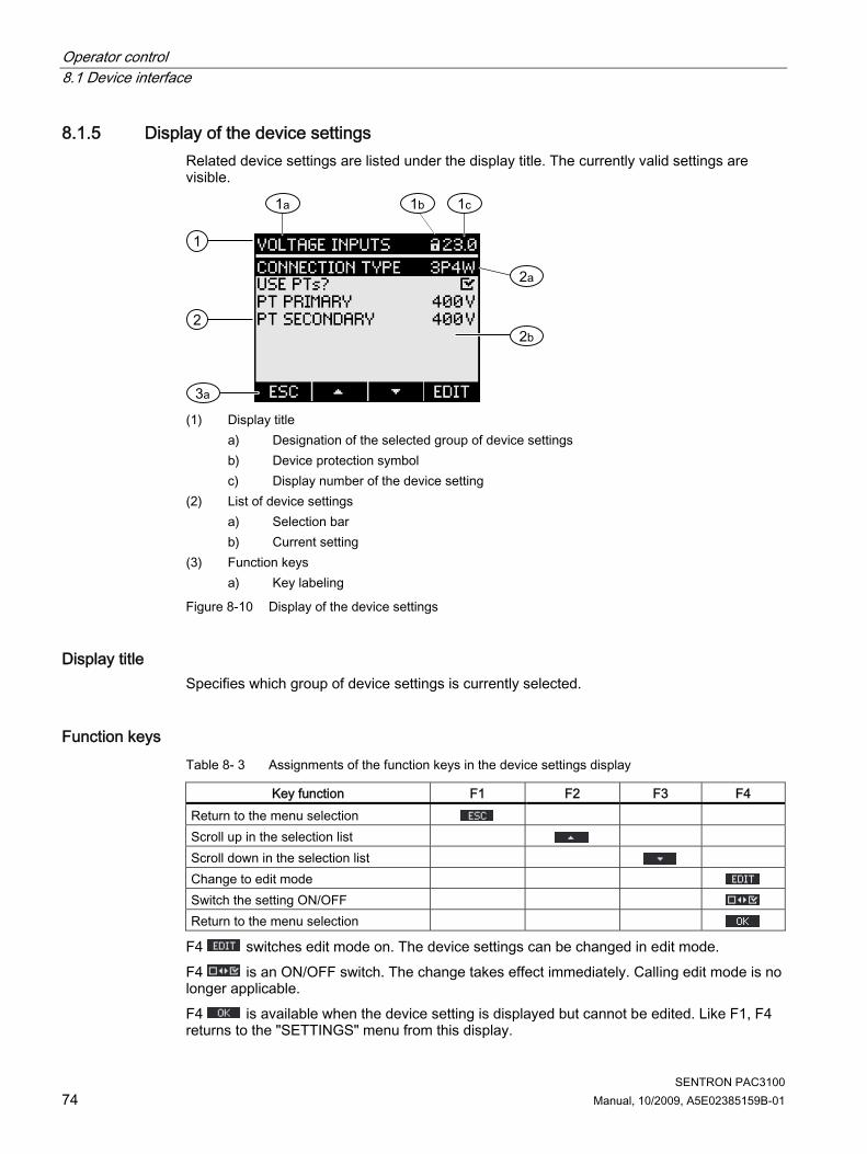
Operator control 8.1 Device interface
SENTRON PAC3100 74 Manual, 10/2009, A5E02385159B-01
8.1.5 Display of the device settings Related device settings are listed under the display title. The currently valid settings are visible.
(1) Display title a) Designation of the selected group of device settings b) Device protection symbol c) Display number of the device setting (2) List of device settings a) Selection bar b) Current setting (3) Function keys a) Key labeling
Figure 8-10 Display of the device settings
Display title Specifies which group of device settings is currently selected.
Function keys Table 8- 3 Assignments of the function keys in the device settings display
Key function F1 F2 F3 F4 Return to the menu selection Scroll up in the selection list Scroll down in the selection list Change to edit mode Switch the setting ON/OFF Return to the menu selection
F4 switches edit mode on. The device settings can be changed in edit mode. F4 is an ON/OFF switch. The change takes effect immediately. Calling edit mode is no longer applicable. F4 is available when the device setting is displayed but cannot be edited. Like F1, F4 returns to the "SETTINGS" menu from this display.

Operator control 8.1 Device interface
SENTRON PAC3100 Manual, 10/2009, A5E02385159B-01 75
See also Edit mode of the device settings (Page 75) Operator input steps in device settings display (Page 79)
8.1.6 Edit mode of the device settings To edit the device settings, it is necessary to call edit mode. In display mode, the function for calling edit mode is assigned to F4 . You can recognize edit mode because the selection bar reduces to the width of the selected value.
(1) Group title (2) List of device settings a) Device setting in edit mode
Figure 8-11 Edit mode of the device settings
Note Edit functions in display mode Display mode also includes edit functions. In display mode, F4 functions as an ON/OFF switch with immediate effect. Calling edit mode is no longer applicable.

Operator control 8.2 Steps
SENTRON PAC3100 76 Manual, 10/2009, A5E02385159B-01
Function keys
Table 8- 4 Assignments of the function keys in edit mode of the device settings
Key function F1 F2 F3 F4 Reject the changes and return to display mode
Increment the numerical value by "1" or show the next selectable setting
Decrement the numerical value by "1" Go to the next digit to the right in the multi-digit numerical value
Save the changes and return to display mode
See also Display of the device settings (Page 74) Operator input steps in device settings display (Page 79)
8.2 Steps
8.2.1 Operator input steps in the measured variable display
Selecting the measured variable When displaying the instantaneous value, it is possible to switch to other measured variables. F2 switches to the previous measured variable. F3 switches to the next measured variable. The order of the measured variables corresponds to the order in the main menu. If the maximum/minimum value or average value is displayed, F2 and F3 are not available. In this case, switch first to the display of the instantaneous value. Note: It is also possible to select the measured variable in the main menu.

Operator control 8.2 Steps
SENTRON PAC3100 Manual, 10/2009, A5E02385159B-01 77
Display minimum, maximum, and instantaneous value F1 switches the display on. F1 : Display of the maximum value F1 : Display of the minimum value F1 : Display of the instantaneous value
Reset the maximum or minimum value to the instantaneous value F3 resets the last reached maximum/minimum value to the instantaneous value.
Figure 8-12 Reset the maximum or minimum value to the instantaneous value
Calling the "MAIN MENU" F4 calls the menu selection. The selection bar is at the last displayed measured variable in the menu selection.
Figure 8-13 Calling the "MAIN MENU"
See also Operator input steps in the "MAIN MENU" (Page 78)

Operator control 8.2 Steps
SENTRON PAC3100 78 Manual, 10/2009, A5E02385159B-01
8.2.2 Operator input steps in the "MAIN MENU"
Selecting the measured variable The selection bar highlights the currently selected menu entry (white text on a black background). F2 moves the selection bar up in the menu list. F3 moves the selection bar down in the menu list.
Note Selecting the measured variable In the measured value display, you can switch to other measured value displays without calling the main menu.
Displaying the measured variable The selection bar highlights the currently selected menu entry (white text on a black background). F4 calls the display of the selected measured variable.
Cancel menu selection F1 cancels menu selection and returns to the last displayed measured variable.
Note Cancel menu selection When returning from the main menu to the measured value display, the display switches to showing the instantaneous value.
Figure 8-14 Cancel menu selection
Calling the "SETTINGS" menu The "SETTINGS" menu entry calls the menu for parameterizing the device.
See also Operator input steps in the measured variable display (Page 76)

Operator control 8.2 Steps
SENTRON PAC3100 Manual, 10/2009, A5E02385159B-01 79
8.2.3 Operator input steps in the "SETTINGS" menu
Selecting settings The selection bar highlights the currently selected menu entry (white text on a black background). F2 moves the selection bar up in the menu list. F3 moves the selection bar down in the menu list.
Displaying a setting The selection bar highlights the currently selected menu entry (white text on a black background). F4 calls the display of the selected device setting.
Figure 8-15 Displaying settings
Cancel menu selection F1 returns to the main menu.
8.2.4 Operator input steps in device settings display
Calling edit mode F4 switches edit mode on. The device settings can be changed in edit mode. You can recognize edit mode because the selection bar reduces to the width of the selected value.
Figure 8-16 Calling edit mode

Operator control 8.2 Steps
SENTRON PAC3100 80 Manual, 10/2009, A5E02385159B-01
Exiting the display F1 closes the display and returns to the "SETTINGS" menu.
Figure 8-17 Exiting the display
8.2.5 Operator input steps in edit mode of the device settings
Enter password If device protection is switched on, the SENTRON PAC3100 demands input of the valid password.
Figure 8-18 Enter password
You can find information on password management in the "Password management" chapter.
Change value Switching a device setting ON/OFF F4 switches a function or status ON/OFF. The setting takes effect immediately. Saving with F4 no longer applies.
Figure 8-19 Switching a device setting ON/OFF
Switching between several options F4 switches between options that cannot be in effect at the same time. When an option is switched on, the last valid option is switched off. The setting takes effect immediately. Saving with F4 no longer applies.

Operator control 8.2 Steps
SENTRON PAC3100 Manual, 10/2009, A5E02385159B-01 81
Figure 8-20 Switching the device setting
Selecting from several settings F2 scrolls up through the range of selectable settings. F3 scrolls down through the range of selectable settings.
Figure 8-21 Selecting from several settings
Incrementing or decrementing a value F2 increases the value in increments of 1. F3 decreases the value in decrements of 1. The highest value of the available set of values is followed again by the lowest. Defining multi-digit values If F3 is available, the digits of a value can be changed, e.g. specific address digits of an address value. F3 runs through the digits of the value from left to right. F2 increments the value at the selected digit. The highest value of the available set of values is followed again by the lowest.
Saving the value F4 saves the set value and returns to display mode.
Canceling editing F1 cancels editing and returns to display mode. All changes are discarded.
Figure 8-22 Exiting edit mode

Operator control 8.2 Steps
SENTRON PAC3100 82 Manual, 10/2009, A5E02385159B-01
See also Password management (Page 95)

SENTRON PAC3100 Manual, 10/2009, A5E02385159B-01 83
Parameterizing 99.1 Introduction
Device settings The "Parameterizing" chapter describes the device settings. These functions include: ● Adjustment to the physical conditions of use ● Integration into the communication system ● Country-specific settings, ergonomics, device protection It is possible to set the device by means of: ● The operator interface of the device ● Configuration software ● RS 485 interface
Note Protection of the device settings As delivered, the device settings are not protected. At startup, a password should be assigned and the device protection activated to guard against unauthorized or inadvertent changes.
9.2 Parameterizing the operator interface
9.2.1 Groups of settings The device settings are arranged into the following groups. The "SETTINGS" menu shows the choice of groups: ● Device information
Device-specific numbers and versions. ● Language/Regional
Display language and designation of the phases on the display. ● Basic parameters
Settings for measuring inputs for voltage and current. ● Power demand
Setting of the period duration and synchronization. ● Energy counter
Settings for active energy and reactive energy.

Parameterizing 9.2 Parameterizing the operator interface
SENTRON PAC3100 84 Manual, 10/2009, A5E02385159B-01
● Integral I/O Settings for using the digital outputs.
● Communication Settings for Modbus RTU communication.
● Display Settings for the display.
● Advanced Password protection, resetting the device.
9.2.2 Device information The device information cannot be modified. Key F4 returns to the "SETTINGS" menu. Call: "SETTINGS > DEVICE INFORMATION"
Figure 9-1 Device setting "DEVICE INFORMATION"
Device information PAC3100 V1.00 Device designation and version 7KM31 . . - . . . . . - . . . . Order number of the device. S/N: Serial number of the device. D/T: Date code. ES: Hardware revision level. SW-REV: Firmware revision level. BL-REV: Boot loader revision level. LP-REV: Language pack revision level.

Parameterizing 9.2 Parameterizing the operator interface
SENTRON PAC3100 Manual, 10/2009, A5E02385159B-01 85
9.2.3 Language and regional settings Display language and designation of the phases on the display. Call: "SETTINGS > LANGUAGE/REGIONAL"
Figure 9-2 "LANGUAGE SETTING" device setting
Language and regional settings LANGUAGE Language of the display. Range: German, English, Portuguese, Turkish,
Spanish, Italian, French, Chinese, Russian1) 1) Russian in a separate language pack, installable with the SENTRON powerconfig configuration software Version V2.1
Default value:
English
PHASE LABELS Designation of the phases on the display. Range: L1 L2 L3, a b c Default value: L1 L2 L3
9.2.4 Basic parameters Basic parameters are all those settings concerning the measuring inputs. Call: "SETTINGS > BASIC PARAMETERS"

Parameterizing 9.2 Parameterizing the operator interface
SENTRON PAC3100 86 Manual, 10/2009, A5E02385159B-01
Figure 9-3 "BASIC PARAMETERS" device setting
VOLTAGE INPUTS
Figure 9-4 "VOLTAGE INPUTS" device setting
CONNECTION TYPE Connection types: 3P4W: 3 phases, 4 conductors,
unbalanced load 3P3W: 3 phases, 3 conductors,
unbalanced load Default value: 3P4W Use PTs? Measurement with/without voltage transformer ON/OFF switch: ON / OFF.
ON: Measurement using voltage transformers. When measuring via voltage transformer, the device must know the voltage conversion ratio. For this purpose, the primary and secondary voltages must be specified in the fields "PT PRIMARY" and "PT SECONDARY". When changing from direct measurement to measurement using voltage transformers, the device accepts the last set reference measuring voltage as the secondary voltage and as the primary voltage.
OFF: Measurement direct on the low-voltage system. When changing from measurement using voltage transformers to direct measurement, the device accepts the last set secondary voltage as the reference measuring voltage. Default value: Off

Parameterizing 9.2 Parameterizing the operator interface
SENTRON PAC3100 Manual, 10/2009, A5E02385159B-01 87
VOLTAGE INPUT Rated voltage of the measuring system. Must be specified if measuring is done direct on the system without voltage transformers.
Range: 1 V to 480 V, freely adjustable Default value: 400 V
The property "VOLTAGE INPUT" is only visible, if "USE PTs?" is set to " Off".
PT PRIMARY Primary voltage. Must be specified if a voltage transformer is used for measuring.
Range: 1 V to 999999 V, freely adjustable Default value: 400 V
The property "PT PRIMARY" is only visible, if "USE PTs?" is set to " On".
PT SECONDARY Secondary voltage. Must be specified if a voltage transformer is used for measuring.
Range: 1 V to 480 V, freely adjustable Default value: 400 V
The property "PT SECONDARY" is only visible, if "USE PTs?" is set to " ON".
CURRENT INPUT
Figure 9-5 "CURRENT INPUTS" device setting
CAUTION Please note current carrying capacity Overload can destroy the SENTRON PAC3100.
The device must know the current conversion ratio. The primary current must be set in the "CT PRIMARY" field for this purpose. The secondary current is fixed. The "CT SECONDARY" field is a display field. CT PRIMARY Primary current of the current transformers. Range: 1 A to 99999 A, freely adjustable.
Default value: 50 A
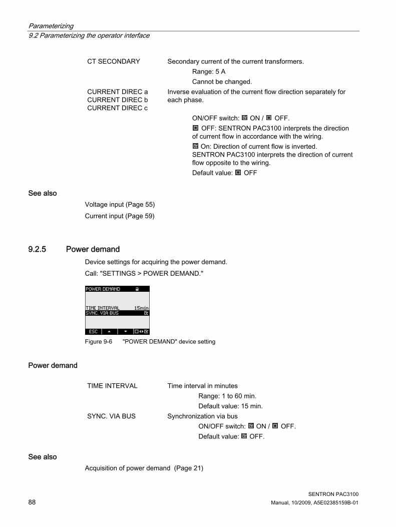
Parameterizing 9.2 Parameterizing the operator interface
SENTRON PAC3100 88 Manual, 10/2009, A5E02385159B-01
CT SECONDARY Secondary current of the current transformers. Range: 5 A
Cannot be changed. CURRENT DIREC a CURRENT DIREC b CURRENT DIREC c
Inverse evaluation of the current flow direction separately for each phase.
ON/OFF switch: ON / OFF. OFF: SENTRON PAC3100 interprets the direction
of current flow in accordance with the wiring. On: Direction of current flow is inverted.
SENTRON PAC3100 interprets the direction of current flow opposite to the wiring. Default value: OFF
See also Voltage input (Page 55) Current input (Page 59)
9.2.5 Power demand Device settings for acquiring the power demand. Call: "SETTINGS > POWER DEMAND."
Figure 9-6 "POWER DEMAND" device setting
Power demand TIME INTERVAL Time interval in minutes Range: 1 to 60 min.
Default value: 15 min. SYNC. VIA BUS Synchronization via bus ON/OFF switch: ON / OFF.
Default value: OFF.
See also Acquisition of power demand (Page 21)

Parameterizing 9.2 Parameterizing the operator interface
SENTRON PAC3100 Manual, 10/2009, A5E02385159B-01 89
9.2.6 Energy counters Device settings for energy counting. Call: "SETTINGS > ENERGY COUNTERS"
Energy counters ACTIVE ENERGY Counter for active energy Range: BALANCE Balance of imported and exported active
energy. IMPORT Imported active energy. EXPORT Exported active energy. Default value: BALANCE REACTIVE ENERGY Counter for reactive energy Range: BALANCE Balance of imported and exported
reactive energy. IMPORT Imported reactive energy. EXPORT Exported reactive energy. Default value: BALANCE
See also Energy counters (Page 22)
9.2.7 Integrated I/Os Device settings for using the digital inputs and outputs. Call: "SETTINGS > INTEGRATED I/O".
Figure 9-7 "INTEGRATED I/O" device setting

Parameterizing 9.2 Parameterizing the operator interface
SENTRON PAC3100 90 Manual, 10/2009, A5E02385159B-01
"DIG. OUTPUT 0" Digital output DO0 (terminal labeling).
Figure 9-8 Device setting "DIG. OUTPUT 0"
ACTION Method of using the digital output: OFF The digital output is switched off. REMOTE OUTPUT The digital output is controlled via the
RS 485 interface. ENERGY PULSE The digital output outputs the
parameterized number of pulses per energy unit. For this purpose, the energy counter specified in the "SOURCE" field and the "PULSES PER UNIT" field are evaluated.
Default value: OFF. SOURCE The field is available with the action "ENERGY PULSE".
The field selects the type of cumulated power: Active energy or reactive energy, import or export of energy. Range:
kWh IMPORT kWh EXPORT kVARh IMPORT kVARh EXPORT
Default value: kWh IMPORT The subdivision of the import value is defined in the field "PULSES PER UNIT".
PULSES PER UNIT
The field is available with the action "ENERGY PULSE". Number of pulses per unit. The unit is defined in the "SOURCE" field.
Range: 1 to 999 Default value: 10
PULSE LENGTH The field is available with the action "ENERGY PULSE". Pulse length.
Range: 30 to 500 ms Default value: 100 ms
The minimum length of the pulse pause corresponds to the pulse duration specified.

Parameterizing 9.2 Parameterizing the operator interface
SENTRON PAC3100 Manual, 10/2009, A5E02385159B-01 91
"DIG. OUTPUT 1" Digital output DO1 (terminal labeling). All fields as digital output "DIG. OUTPUT 0".
"DIG. INPUT 0" Digital input DI0 (terminal labeling). Status display only. No parameter assignment provided. Digital input switched Digital input not switched
"DIG. INPUT 1" Digital input DI1 (terminal labeling). All fields as digital output "DIG. OUTPUT 0".
See also Digital inputs and outputs (Page 23)
9.2.8 Communication Device settings of the RS 485 interface. Call: "SETTINGS > COMMUNICATION"
RS 485 interface The device can be parameterized via the RS 485 interface. The following settings are possible on the display.
Supported address area. Range: 1 … 247
(Each device on the bus must have a unique address).
ADDRESS
Default value:
126
Supported baud rates in baud. Range: 4800, 9600, 19200, 38400
BAUD RATE
Default value:
19200
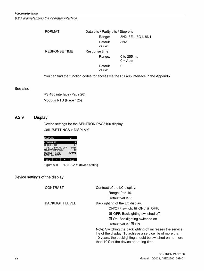
Parameterizing 9.2 Parameterizing the operator interface
SENTRON PAC3100 92 Manual, 10/2009, A5E02385159B-01
Data bits / Parity bits / Stop bits Range: 8N2, 8E1, 8O1, 8N1
FORMAT
Default value:
8N2
Response time Range: 0 to 255 ms
0 = Auto
RESPONSE TIME
Default value:
0
You can find the function codes for access via the RS 485 interface in the Appendix.
See also RS 485 interface (Page 26) Modbus RTU (Page 125)
9.2.9 Display Device settings for the SENTRON PAC3100 display. Call: "SETTINGS > DISPLAY"
Figure 9-9 "DISPLAY" device setting
Device settings of the display CONTRAST Contrast of the LC display. Range: 0 to 10.
Default value: 5 BACKLIGHT LEVEL Backlighting of the LC display. ON/OFF switch: ON / OFF.
OFF: Backlighting switched off On: Backlighting switched on
Default value: ON. Note: Switching the backlighting off increases the service
life of the display. To achieve a service life of more than 10 years, the backlighting should be switched on no more than 10% of the device operating time.

Parameterizing 9.2 Parameterizing the operator interface
SENTRON PAC3100 Manual, 10/2009, A5E02385159B-01 93
TIME UNTIL DIMMED Time after which the device switches off the backlighting. Range: 0 to 99 min.
0 = Backlighting remains switched on Default value: 3 min.
INVERT DISPLAY Inversion of the basic representation of the display. ON/OFF switch: ON / OFF.
OFF: Light text on dark background. ON: Dark text on light background.
Default value: ON. REFRESH TIME Refresh rate of the display. Range: 330 to 3000 ms
Default value: 330 ms. The tolerance of the refresh rate is 100 ms.
DISPLAY TEST Screen for testing the functional capability of the display. Key F3 inverts the test screen.
Key F4 closes the display.
9.2.10 Advanced Call: "SETTINGS > ADVANCED". Other device settings. ● Password protection ● Resetting of minimum/maximum values, counters, and communication parameters
Figure 9-10 "ADVANCED" device setting

Parameterizing 9.2 Parameterizing the operator interface
SENTRON PAC3100 94 Manual, 10/2009, A5E02385159B-01
PASSWORD PROTECTION You can protect the device settings against write access with a password. The data can be read without any restrictions. PASSWORD PROTECTION Switches password protection ON / OFF. ON: Password protection switched
on OFF: Password protection switched
off Default value: switched off
PASSWORD Four-digit, numeric password. Default value: 0000
(1) Password protection switched off (2) Password protection switched on
Figure 9-11 "PASSWORD PROTECTION" device setting
See also Password management (Page 95)
RESET The "RESET" dialog box enables resetting of the device settings to the instantaneous values or the factory default values. The following groups of values can be reset: ● Maximum/minimum values ● Counters ● Factory defaults ● Communication parameters F4 does not immediately reset a value group but marks the group instead. The "EXECUTE..." menu entry resets the marked value groups.
NOTICE Restart of the device Resetting to the factory defaults results in restart of the device.

Parameterizing 9.2 Parameterizing the operator interface
SENTRON PAC3100 Manual, 10/2009, A5E02385159B-01 95
NOTICE Access protection is switched off Resetting to the factory defaults deactivates device protection. Password protection is switched off. The password is set to the value "0000".
NOTICE Counter - Reset Resetting to the factory defaults has the effect of resetting all counters!
After calling the "EXECUTE" menu entry with F4 , a safety query appears on the display: ● "ARE YOU SURE YOU WANT TO EXECUTE THE SELECTED FUNCTIONS?" ● "ARE YOU SURE YOU WANT TO EXECUTE THE SELECTED FUNCTIONS?
RESTART REQUIRED" Answer this query with F1 or F4: ● F1 : Cancels the execution. The display returns to display mode. All selected value
groups are deselected. ● F4 : Yes, execute. After execution with F4 , the message "SELECTION EXECUTED" appears on the screen. Confirm the message with F4 . If the device is reset to the factory settings, the message "SELECTION EXECUTED" does not appear. Instead, the device immediately restarts. CLEAR MIN/MAX VALUES Resets all minimum and maximum values to
the instantaneous value. RESET COUNTERS Resets the energy counters to 0 (zero). FACTORY DEFAULTS Resets all device settings to the default
values, with the exception of the communication parameters.
COMMUNICATION PARAM. Resets the entered Modbus RTU parameters.
EXECUTE Reset function. Resets the selected value groups.
9.2.11 Password management
Default password The default password is: 0000 If no user-specific password has been assigned, the default password must be entered when password protection is switched on.

Parameterizing 9.2 Parameterizing the operator interface
SENTRON PAC3100 96 Manual, 10/2009, A5E02385159B-01
9.2.11.1 Calling password management You can find password management in the device settings under "ADVANCED > PASSWORD"
To access password management: 1. Exit the measured value display. Call the "MAIN MENU":
F4 2. In the main menu, go to the "SETTINGS" entry:
F2 or F3 3. Call the "SETTINGS" entry:
F4 4. In the "SETTINGS" menu, go to the "ADVANCED" entry:
F2 or F3 5. Call the "ADVANCED" entry:
F4 6. In the "ADVANCED" menu, call the "PASSWORD PROTECTION" entry:
F4
9.2.11.2 Switch on password protection Password protection can be switched on at any time.
NOTICE Password known? Before you switch on password protection, make sure you and the group of authorized users are all in possession of the password. If password protection is switched on, the password is mandatory for all changes to the device settings. You also require the password to call the "PASSWORD" dialog box again in order to switch off access protection or to change the password.
Password protection is effective as soon as it is switched on! The password protection symbol in the display title changes from "unprotected" to "protected". While you are in the "PASSWORD PROTECTION" dialog box, you can switch password protection off again or view the password in the "PASSWORD" field.

Parameterizing 9.2 Parameterizing the operator interface
SENTRON PAC3100 Manual, 10/2009, A5E02385159B-01 97
To switch password protection on, proceed as follows: 1. Call the "PASSWORD PROTECTION" display. 2. Activate the field "PASSWORD PROTECTION" with
F4
(1) Password protection switched off (2) Password protection switched on Figure 9-12 "PASSWORD PROTECTION" device setting
9.2.11.3 Switch off password protection If password protection is switched off, there is no protection against unauthorized or inadvertent changes to the device settings. The currently valid password becomes visible on the display when password protection is switched off. The password remains saved and becomes effective again the next time password protection is switched on.
Note Password visible on the display The password becomes visible on the display when password protection is switched off.
To switch off password protection: 1. Call the "PASSWORD PROTECTION" display. 2. Deactivate the "PASSWORD PROTECTION" field with
F4 The device opens the "ENTER PASSWORD" dialog box.
3. Enter the password and confirm with F4 The display returns to the "PASSWORD PROTECTION" display. The password is visible on the display.
If you have given the correct password, password protection is switched off. If you have given an incorrect password, password protection remains active. Start again at Step 2 and enter the correct password.
Parameterizing 9.2 Parameterizing the operator interface
SENTRON PAC3100 98 Manual, 10/2009, A5E02385159B-01
9.2.11.4 Change password The password can be changed whether access protection is on or off. If access protection is switched on, the currently valid password is required in order to change the password.
Initial situation: Password protection switched off If password protection is switched off, the password is also unprotected and can therefore be changed without restriction.
To change the password: 1. Call the "PASSWORD PROTECTION" display. 2. Go to the "PASSWORD" device setting:
F2 or F3 3. Open edit mode of the "PASSWORD" device setting:
F4 4. Change the password with:
F2 and F3 5. Accept the new password with:
F4 The password is permanently saved. The display returns to display mode.
Initial situation: Password protection switched on: If password protection is switched on, the valid password must be entered in order to change the password.
To change the password: 1. Call the "PASSWORD PROTECTION" display. 2. Go to the "PASSWORD" device setting:
F2 or F3 3. Open edit mode of the "PASSWORD" device setting:
F4 4. The device opens the "ENTER PASSWORD" dialog box. 5. Enter the password and confirm with
F4 If you have entered the correct password, the password becomes visible in the PASSWORD field.
6. Open edit mode of the device setting "PASSWORD" with: F4
7. Change the password with: F2 and F3
8. Accept the new password with: F4

Parameterizing 9.2 Parameterizing the operator interface
SENTRON PAC3100 Manual, 10/2009, A5E02385159B-01 99
The password is permanently saved and becomes effective immediately. The display returns to display mode. The newly assigned password remains visible until you exit the dialog box with F1 .
9.2.11.5 Password lost - what to do? If you have forgotten the password, please contact Technical Assistance. You will receive a new password from them. You can find the address of Technical Assistance in the Chapter "Introduction".
Requesting a new password Have the serial number of the device ready when making telephone enquiries or include the serial number in written enquiries. The serial number is printed on the device housing and is specified in "SETTINGS > DEVICE INFORMATION".
NOTICE Change password immediately on receipt As soon as you receive the new password, you must change it and inform the group of authorized users.
See also Latest information and correction sheet (Page 12) Labeling (Page 113)

Parameterizing 9.2 Parameterizing the operator interface
SENTRON PAC3100 100 Manual, 10/2009, A5E02385159B-01
SENTRON PAC3100 Manual, 10/2009, A5E02385159B-01 101
Service and maintenance 1010.1 Calibration
The device has been calibrated by the manufacturer before shipping. Recalibration is not required provided the environmental conditions are maintained.
10.2 Cleaning Clean the display and the keypad periodically. Use a dry cloth for this.
CAUTION Damage due to detergents Detergents can damage the device. Do not use detergents.
10.3 Firmware updates The SENTRON PAC3100 supports firmware updates. Use the SENTRON powerconfig software, Version V2.1 or higher, to install all updates. For update instructions, please see the related documentation. The update function is password protected. The last devices settings made remain unchanged.
Repeating the firmware update after cancellation
NOTICE Cancellation of a firmware update puts the device out of commission Please ensure there is uninterrupted power supply. Ensure the configuration software completes the update properly.
The device loses the current firmware if the update operation is cancelled. The device cannot function without firmware. It is necessary to repeat the update to restore functionality of the device. After cancellation of an update operation, the firmware of the device can no longer be read out. The configuration software must therefore obtain the currently set communication parameters of the device from another source, e.g. by manual input.

Service and maintenance 10.4 Repair
SENTRON PAC3100 102 Manual, 10/2009, A5E02385159B-01
Communication parameters are known 1. Inform the configuration software of the communication parameters necessary for
accessing the device. 2. Start the firmware update. Communication parameters are not known 1. Reset the communication parameters of the device to the factory defaults:
– Interrupt the power supply of the device. – Press <F1>, <F2> and <F4> simultaneously on the device while reapplying the supply
voltage. 2. Set up the configuration software in such a way that the device can be accessed with the
default communication parameters. The default values are listed in the Technical Data. 3. Start the firmware update.
See also Technical data (Page 105)
10.4 Repair
Procedure
NOTICE Loss of warranty If you open the device, it loses its Siemens warranty. Only the manufacturer may carry out repairs to the device. Return faulty or damaged devices to Siemens for repair or replacement.
If the device is faulty or damaged, proceed as follows: 1. Deinstall the device. 2. Pack the device in a suitable manner to prevent it from being damaged during transport. 3. Return the device to Siemens. You can obtain the address from:
– Your Siemens sales partner – Technical Assistance
See also Latest information and correction sheet (Page 12) Deinstallation (Page 36)

Service and maintenance 10.5 Disposal
SENTRON PAC3100 Manual, 10/2009, A5E02385159B-01 103
10.5 Disposal
Disposal and recycling Dispose of or recycle the module in accordance with the applicable laws and regulations in your country.

Service and maintenance 10.5 Disposal
SENTRON PAC3100 104 Manual, 10/2009, A5E02385159B-01

SENTRON PAC3100 Manual, 10/2009, A5E02385159B-01 105
Technical data 1111.1 Technical data
Device configuration ● 2 opto-isolated digital inputs ● 2 opto-isolated digital outputs ● 1 RS 485 interface for connecting to the PC or network
Measurement Only for connection to AC voltage systems Measuring method For voltage measurement True root-mean-square measurement (TRMS) For current measurement True root-mean-square measurement (TRMS) Measured value acquisition Energy Contiguous (zero blind measuring) Current, voltage Contiguous (zero blind measuring) Waveform Sinusoidal or distorted Frequency of the relative fundamental 50/60 Hz Measured value acquisition mode Automatic mains frequency acquisition
Measuring inputs for voltage Voltage ph-n 277 V 3 AC (+ 20%) Voltage ph-ph 480 V 3 AC (+ 20%) Min. measurable voltage Voltage ph-n 58 V 3 AC - 80% Voltage ph-ph 100 V 3 AC - 80% Zero point suppression level Voltage ph-n 10 V Voltage ph-ph 17 V Impulse withstand voltage ≤ 6.5 kV (1.2/50 μs) Measuring category (in accordance with IEC/UL 61010 Part 1) Input voltage VI CAT III Input resistance (ph-n) 0.84 MΩ Max. power consumption per phase 131 mW

Technical data 11.1 Technical data
SENTRON PAC3100 106 Manual, 10/2009, A5E02385159B-01
Measuring inputs for current Only for connection to AC power systems via external current transformers Input current II x / 5 A 3 AC (+ 20%) Max. permissible continuous current 10 A Current impulse overload capability 100 A for 1 s Zero point suppression level throughout phases 10 mA in the neutral conductor 45 mA Max. power consumption per phase 500 mVA at 6 A
Measuring accuracy Measured variable Accuracy class in accordance with
IEC 61557-12:2007-08 (K55) Voltage 1 Current 1 Apparent power 1 Active power 1 Reactive power 3 Total apparent power over all phases 1 Total active power over all phases 1 Total reactive power VAR1 over all phases 3 Cumulated active power 1 Cumulated reactive power 3 Total power factor 2 Line frequency 0,1 Active energy 1 Reactive energy 3
When measuring on external current transformers or voltage transformers, the accuracy of the measurement depends on the quality of the transformer.
Power supply Design of the power supply Wide-range power supply AC / DC Rated range 100 … 240 V AC (45 … 65 Hz) or
110 … 250 V DC Work area ± 10% of AC/DC rated range Power consumption 5 W DC / 10 VA AC Overvoltage category CAT III

Technical data 11.1 Technical data
SENTRON PAC3100 Manual, 10/2009, A5E02385159B-01 107
Digital inputs Number 2 Type Internal power supply External operating voltage 0 ... 30 V DC (optional) Contact resistor "1" signal detection ≤ 1 kΩ "0" signal detection ≥ 100 kΩ Input current "1" signal detection 2.5 … 10 mA "0" signal detection ≤ 0.5 mA
Digital outputs Number 2 Type Bidirectional Design/function Switching output or pulse output Rated voltage 0 ... 30 V DC, typical 24 V DC
(SELV or PELV supply) Output current For signal "1" Depends on the load and the external power
supply Continuous load ≤ 50 mA (thermal overload protection) Transient overload ≤ 130 mA for 100 ms For signal "0" ≤ 0.2 mA Internal resistance 55 Ω Overvoltage category CAT I Pulse output function Standard for pulse emitter Signal characteristics in accordance with
IEC 62053-31 Adjustable pulse duration 30 … 500 ms Min. settable time frame 10 ms Max. switching frequency 17 Hz Short-circuit protection Yes
Communication RS 485 interface Electrical interface RS 485, two-wire line + 1 line for Common Connection type Terminal block with screw terminals Supported communication protocol Modbus RTU

Technical data 11.1 Technical data
SENTRON PAC3100 108 Manual, 10/2009, A5E02385159B-01
Functionality Slave Supported baud rate 4800, 9600, 19200, 38400
Default: 19200 Data format 8N1, 8N2, 8E1, 8O1
Default value: 8N2 Supported address area 1 to 247
Default value: 126
Retention of data in the absence of the supply voltage Measured values and counters are monitored for minimum and maximum values at specific intervals and only saved to the non-volatile memory in the event of a change. This means the age of the data before the power failure is as follows: ● Minimum and maximum values max. 5 s ● Counters max. 5 min
Display and operator control Display Type Monochrome, graphical LC display, light
backlighting, dark text and digits Backlighting White, invertible display Service life of the LEDs 25,000 hours at 25 °C ambient temperature.
To achieve a service life of at least 10 years, the backlighting should be switched on no more than 10% of the device operating time.
Resolution 128 x 96 pixels Size W x H 72 mm x 54 mm Refresh time 0.33 ... 3 s, adjustable Keyboard 4 function keys F1 to F4 on the front, multiple assignments
Connection elements Measuring inputs and supply voltage inputs Screw terminal
Connection designations IL1(°↑k, l↓), IL2(°↑k, l↓), IL3(°↑k, l↓) V1, V2, V3, VN, L/+, N/- 1-wire or 2-wire connection possible

Technical data 11.1 Technical data
SENTRON PAC3100 Manual, 10/2009, A5E02385159B-01 109
Conductor cross section Solid 1 x 0.5 ... 4.0 mm²
AWG 1 x 20 ... 12 2 x 0.5 ... 2.5 mm² AWG 2 x 20 ... 14
Finely stranded with end sleeve 1 x 0.5 ... 2.5 mm² AWG 1 x 20 ... 14 2 x 0.5 ... 1.5 mm² AWG 2 x 20 ... 16
Stripping length 10 mm Connection screws Tightening torque 0.8 ... 1.2 Nm
7 ... 10.3 lbf·in Tool Screwdriver PZ2
cal. ISO 6789 Crimping tool in accordance with EN 60947-1
Digital outputs, digital inputs Screw terminal
Connection designations , DIC, DI1, DI0, DOC, DO1, DO0 Conductor cross section Solid 1 x 0.2 ... 2.5 mm²
2 x 0.2 ... 1.0 mm² Finely stranded without end sleeve 1 x 0.2 ... 2.5 mm²
2 x 0.2 ... 1.5 mm² Finely stranded with end sleeve, without
plastic sleeve 1 x 0.25 ... 2.5 mm² 2 x 0.25 ... 1.0 mm²
Finely stranded with end sleeve, with plastic sleeve
1 x 0.25 ... 2.5 mm²
Finely-stranded with TWIN end sleeve, with plastic sleeve
2 x 0.5 ... 1.5 mm²
AWG cables 1 x 24 ... 12 Stripping length 7 mm Connection screws Tightening torque 0.5 ... 0.6 Nm Tool Screwdriver PZ1
cal. ISO 6789 Crimping tool in accordance with EN 60947-1

Technical data 11.1 Technical data
SENTRON PAC3100 110 Manual, 10/2009, A5E02385159B-01
RS 485 connector Screw terminal
Connection designations Com, +/B, -/A Conductor cross section Solid 1 x 0.2 ... 2.5 mm²
2 x 0.2 ... 1.0 mm² Finely stranded without end sleeve 1 x 0.2 ... 2.5 mm²
2 x 0.2 ... 1.5 mm² Finely stranded with end sleeve, without
plastic sleeve 1 x 0.25 ... 2.5 mm² 2 x 0.25 ... 1.0 mm²
Finely stranded with end sleeve, with plastic sleeve
1 x 0.25 ... 2.5 mm²
Finely-stranded with TWIN end sleeve, with plastic sleeve
2 x 0.5 ... 1.5 mm²
AWG cables 1 x 24 ... 12 Stripping length 7 mm Connection screws Tightening torque 0.5 ... 0.6 Nm Tool Screwdriver PZ1
cal. ISO 6789 Crimping tool in accordance with EN 60947-1
Dimensions and weights Type of fixing Panel mounting to IEC 61554 Housing dimensions W x H x D 96 mm x 96 mm x 56 mm Cutout (W x H) 92+0.8 mm x 92+0.8 mm Overall depth 51 mm Permissible switching panel thickness for installation
≤ 4 mm
Mounting position Vertical Weight Device without packaging Approximately 325 g Device including packaging Approximately 460 g

Technical data 11.1 Technical data
SENTRON PAC3100 Manual, 10/2009, A5E02385159B-01 111
Degree of protection and protection class Protection class Protection class II when installed Degree of protection according to IEC 60529 Device front IP65
Type 5 enclosure acc. to UL50 Device rear IP20 If higher degree of protection requirements are placed on the application engineering, the
customer must take suitable measures
Environmental conditions The device is suitable for switch panel mounting in accordance with IEC 61554. Operation is only permissible inside an enclosed dry room. Temperature range Ambient temperature during operating
phase - 10 °C to + 55 °C
Ambient temperature during transport and storage
- 25 °C to + 70 °C
Relative humidity 95% at 25°C without condensation (normal conditions)
Installation altitude above sea level max. 2000 m Degree of pollution 2 Environmental tests In accordance with IEC 60068

Technical data 11.1 Technical data
SENTRON PAC3100 112 Manual, 10/2009, A5E02385159B-01
Safety regulations CE conformity
The SENTRON PAC3100 complies with the requirements of the following European Directives: DIRECTIVE 2004/108/EC OF THE EUROPEAN PARLIAMENT AND COUNCIL of December 15, 2004, on the approximation of the laws of the Member States relating to electromagnetic compatibility and repealing the Directive 89/336/EEC DIRECTIVE 2006/95/EC OF THE EUROPEAN PARLIAMENT AND COUNCIL of December 12, 2006, on the harmonization of the laws of the Member States relating to electrical equipment designed for use within certain voltage limits Conformity with these Directives is verified by compliance with the following standards: EN 55011:2007; Group 1, Class A DIN EN 61000-6-2:2006 DIN EN 61000-4-2:2001 DIN EN 61000-4-5:2007 DIN EN 61000-4-6:2001 DIN EN 61000-4-8:2001 DIN EN 61000-4-11:2005 DIN EN 61010-1:2002 DIN EN 61326-1:2006 Approvals for the USA and Canada
The SENTRON PAC3100 is approved by UL, File No. E314880. FCC Class A Notice: This device complies with Part 15 of the FCC Rules. Operation is subject to the following two conditions: (1) this device may not cause harmful interference, and (2) this device must accept any interference received, including interference that may cause undesired operation. Approvals for Australia and New Zealand
N117 C-Tick Australian Radiocommunications Act, compliant with AS/NZS CISPR 11; Industrial Emissions Approvals for the Russian Federation

Technical data 11.2 Labeling
SENTRON PAC3100 Manual, 10/2009, A5E02385159B-01 113
11.2 Labeling
Labels on the housing of the SENTRON PAC3100
N117
Figure 11-1 Device labeling
Symbol, label Explanation (1) Product designation (2) Serial number of the device (3)
DC voltage
(4)
Risk of electric shock
(5)
General Warning Symbol
(6)
Overvoltage category CAT III for current and voltage inputs
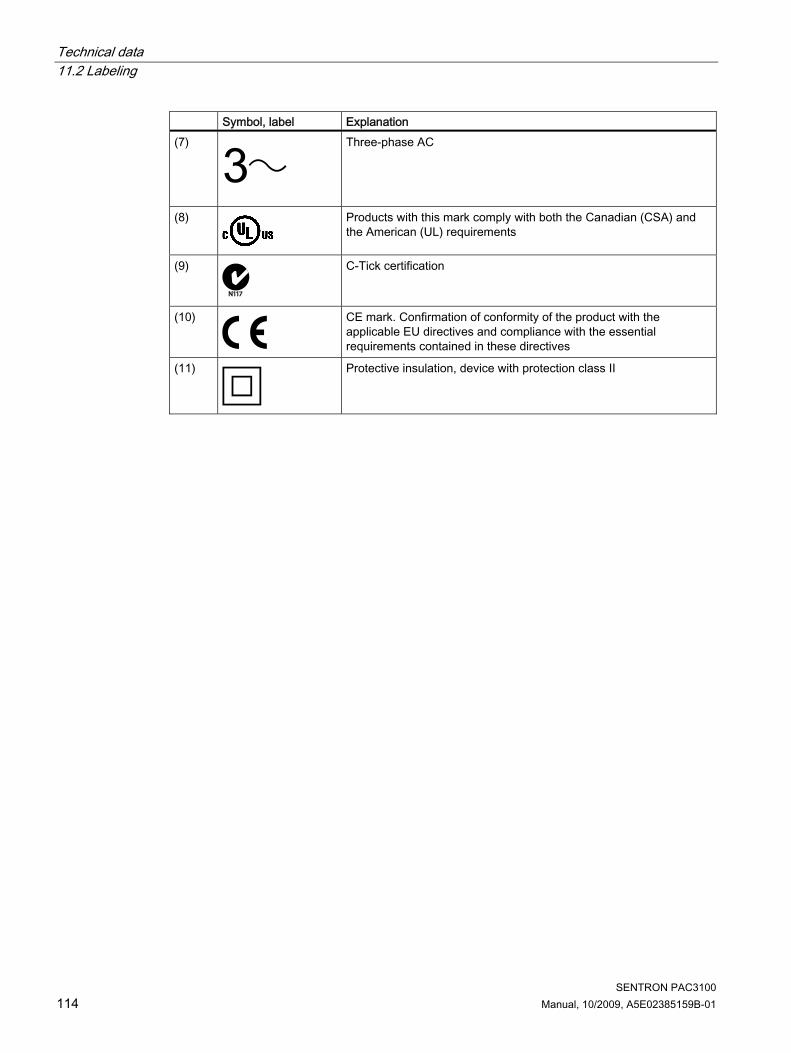
Technical data 11.2 Labeling
SENTRON PAC3100 114 Manual, 10/2009, A5E02385159B-01
Symbol, label Explanation (7)
Three-phase AC
(8)
Products with this mark comply with both the Canadian (CSA) and the American (UL) requirements
(9)
N117
C-Tick certification
(10)
CE mark. Confirmation of conformity of the product with the applicable EU directives and compliance with the essential requirements contained in these directives
(11)
Protective insulation, device with protection class II

SENTRON PAC3100 Manual, 10/2009, A5E02385159B-01 115
Dimensional drawings 12
Note: All dimensions in mm.
Panel cutout
Figure 12-1 Panel cutout
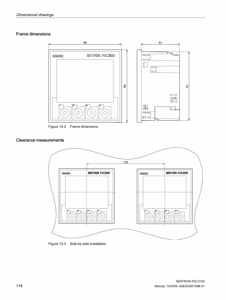
Dimensional drawings
SENTRON PAC3100 116 Manual, 10/2009, A5E02385159B-01
Frame dimensions
Figure 12-2 Frame dimensions
Clearance measurements
Figure 12-3 Side-by-side installation

Dimensional drawings
SENTRON PAC3100 Manual, 10/2009, A5E02385159B-01 117
Clearances
Figure 12-4 Clearances
The clearances specified must be maintained for cable outlets and ventilation.

Dimensional drawings
SENTRON PAC3100 118 Manual, 10/2009, A5E02385159B-01

SENTRON PAC3100 Manual, 10/2009, A5E02385159B-01 119
Appendix AA.1 Measured variables
Measured variables of the SENTRON PAC Power Monitoring Device SENTRON PAC3100 provides the measured variables listed below.
Name Abbrev.
DE + IEC Abbrev. EN + ANSI
Unit Display
Voltage a-n UL1-N Va-n V 1.0 Instantaneous value of the voltage between phase conductor a and the neutral conductor Maximum voltage a-n UL1-N max Va-n max V 1.1 Maximum value of the voltage between phase conductor a and the neutral conductor Minimum voltage a-n UL1-N min Va-n min V 1.2 Minimum value of the voltage between phase conductor a and the neutral conductor Voltage b-n UL2-N Vb-n V 1.0 Instantaneous value of the voltage between phase conductor b and the neutral conductor Maximum voltage b-n UL2-N max Vb-n max V 1.1 Maximum value of the voltage between phase conductor b and the neutral conductor Minimum voltage b-n UL2-N min Vb-n min V 1.2 Minimum value of the voltage between phase conductor b and the neutral conductor Voltage c-n UL3-N Vc-n V 1.0 Instantaneous value of the voltage between phase conductor c and the neutral conductor Maximum voltage c-n UL3-N max Vc-n max V 1.1 Maximum value of the voltage between phase conductor c and the neutral conductor Minimum voltage c-n UL3-N min Vc-n min V 1.2 Minimum value of the voltage between phase conductor c and the neutral conductor Voltage a-b UL1-L2 Va-b V 2.0 Instantaneous value of the voltage between phase conductors a and b Maximum voltage a-b UL1-L2 max Va-b max V 2.1 Maximum value of the voltage between phase conductors a and b Minimum voltage a-b UL1-L2 min Va-b min V 2.2 Minimum value of the voltage between phase conductors a and b Voltage b-c UL2-L3 Vb-c V 2.0 Instantaneous value of the voltage between phase conductors b and c Maximum voltage b-c UL2-L3 max Vb-c max V 2.1 Maximum value of the voltage between phase conductors b and c Minimum voltage b-c UL2-L3 min Vb-c min V 2.2 Minimum value of the voltage between phase conductors b and c
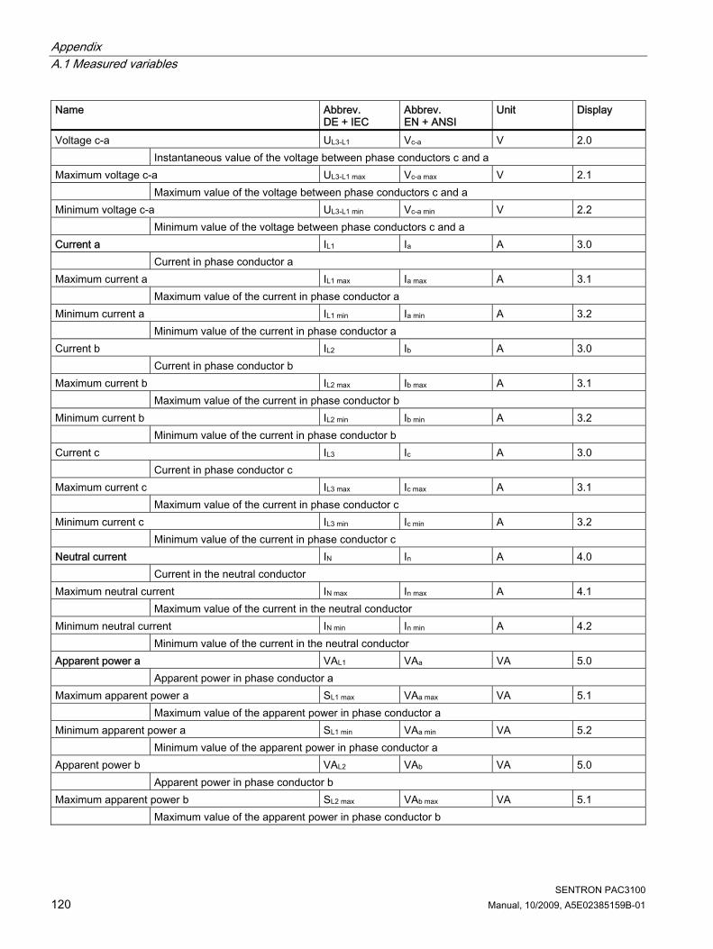
Appendix A.1 Measured variables
SENTRON PAC3100 120 Manual, 10/2009, A5E02385159B-01
Name Abbrev. DE + IEC
Abbrev. EN + ANSI
Unit Display
Voltage c-a UL3-L1 Vc-a V 2.0 Instantaneous value of the voltage between phase conductors c and a Maximum voltage c-a UL3-L1 max Vc-a max V 2.1 Maximum value of the voltage between phase conductors c and a Minimum voltage c-a UL3-L1 min Vc-a min V 2.2 Minimum value of the voltage between phase conductors c and a Current a IL1 Ia A 3.0 Current in phase conductor a Maximum current a IL1 max Ia max A 3.1 Maximum value of the current in phase conductor a Minimum current a IL1 min Ia min A 3.2 Minimum value of the current in phase conductor a Current b IL2 Ib A 3.0 Current in phase conductor b Maximum current b IL2 max Ib max A 3.1 Maximum value of the current in phase conductor b Minimum current b IL2 min Ib min A 3.2 Minimum value of the current in phase conductor b Current c IL3 Ic A 3.0 Current in phase conductor c Maximum current c IL3 max Ic max A 3.1 Maximum value of the current in phase conductor c Minimum current c IL3 min Ic min A 3.2 Minimum value of the current in phase conductor c Neutral current IN In A 4.0 Current in the neutral conductor Maximum neutral current IN max In max A 4.1 Maximum value of the current in the neutral conductor Minimum neutral current IN min In min A 4.2 Minimum value of the current in the neutral conductor Apparent power a VAL1 VAa VA 5.0 Apparent power in phase conductor a Maximum apparent power a SL1 max VAa max VA 5.1 Maximum value of the apparent power in phase conductor a Minimum apparent power a SL1 min VAa min VA 5.2 Minimum value of the apparent power in phase conductor a Apparent power b VAL2 VAb VA 5.0 Apparent power in phase conductor b Maximum apparent power b SL2 max VAb max VA 5.1 Maximum value of the apparent power in phase conductor b

Appendix A.1 Measured variables
SENTRON PAC3100 Manual, 10/2009, A5E02385159B-01 121
Name Abbrev. DE + IEC
Abbrev. EN + ANSI
Unit Display
Minimum apparent power b SL2 min VAb min VA 5.2 Minimum value of the apparent power in phase conductor b Apparent power c VAL3 VAc VA 5.0 Apparent power in phase conductor c Maximum apparent power c SL3 max VAc max VA 5.1 Maximum value of the apparent power in phase conductor c Minimum apparent power c SL3 min VAc min VA 5.2 Minimum value of the apparent power in phase conductor c Active power a PL1 Wa W 6.0 Active power in phase conductor a as import (+) or export (-) Maximum active power a PL1 max Wa max W 6.1 Maximum value of the active power in phase conductor a Minimum active power a PL1 min Wa min W 6.2 Minimum value of the active power in phase conductor a Active power b PL2 Wb W 6.0 Active power in phase conductor b as import (+) or export (-) Maximum active power b PL2 max Wb max W 6.1 Maximum value of the active power in phase conductor b Minimum active power b PL2 min Wb min W 6.2 Minimum value of the active power in phase conductor b Active power c PL3 Wc W 6.0 Active power in phase conductor c as import (+) or export (-) Maximum active power c PL3 max Wc max W 6.1 Maximum value of the active power in phase conductor c Minimum active power c PL3 min Wc min W 6.2 Minimum value of the active power in phase conductor c Reactive power a (VAR1) Q1 L1 VAR1 a var 7.0 Reactive power of the fundamental in phase conductor a, referred to the load counting system,
measured according to VAR1 Maximum reactive power a (VAR1) Q1 L1 max VAR1 a max var 7.1 Maximum reactive power of the fundamental in phase conductor a referred to the load counting
system, measured according to VAR1 Minimum reactive power a (VAR1) Q1 L1 min VAR1 a min var 7.2 Minimum reactive power of the fundamental in phase conductor a, referred to the load counting
system, measured according to VAR1 Reactive power b (VAR1) Q1 L2 VAR1 b var 7.0 Reactive power of the fundamental in phase conductor b, referred to the load counting system,
measured according to VAR1 Maximum reactive power b (VAR1) Q1 L2 max VAR1 b max var 7.1 Maximum reactive power of the fundamental in phase conductor b, referred to the load counting
system, measured according to VAR1

Appendix A.1 Measured variables
SENTRON PAC3100 122 Manual, 10/2009, A5E02385159B-01
Name Abbrev. DE + IEC
Abbrev. EN + ANSI
Unit Display
Minimum reactive power b (VAR1) Q1 L2 min VAR1 b min var 7.2 Minimum reactive power of the fundamental in phase conductor b, referred to the load counting
system, measured according to VAR1 Reactive power c (VAR1) Q1 L3 VAR1 c var 7.0 Reactive power of the fundamental in phase conductor c, referred to the load counting system,
measured according to VAR1 Maximum reactive power c (VAR1) Q1 L3 max VAR1 c max var 7.1 Maximum reactive power of the fundamental in phase conductor c, referred to the load counting
system, measured according to VAR1 Minimum reactive power c (VAR1) Q1 L3 min VAR1 c min var 7.2 Minimum reactive power of the fundamental in phase conductor c, referred to the load counting
system, measured according to VAR1 Total apparent power VA VA VA 8.0 Total apparent power in the phase conductors Maximum total apparent power Smax VAmax VA 8.1 Maximum value of the total apparent power in the three-phase system Minimum total apparent power Smin VAmin VA 8.2 Minimum value of the total apparent power in the three-phase system Total active power P W W 8.0 Total active power in the phase conductors Maximum total active power Pmax Wmax W 8.1 Maximum value of the total active power in the three-phase system Minimum total active power Pmin Wmin W 8.2 Minimum value of the total active power in the three-phase system Total reactive power (VAR1) Q1 VAR1 var 8.0 Root of the total squares of the reactive power of the fundamental in the phase conductors referred to
the load counting system Maximum total reactive power (VAR1) Q1 max VAR1 max var 8.1 Maximum value of the total reactive power of the fundamental in the phase conductors referred to the
load counting system Minimum total reactive power (VAR1) Q1 min VAR1 min var 8.2 Minimum value of the total reactive power of the fundamental in the phase conductors referred to the
load counting system Total power factor PF PF – 9.0 Total power factor Maximum total power factor PFmax PFmax – 9.1 Maximum total power factor Minimum total power factor PFmin PFmin – 9.2 Minimum total power factor Line frequency f f Hz 10.0 Instantaneous value of the line frequency Maximum line frequency fmax fmax Hz 10.1 Maximum value of the line frequency

Appendix A.1 Measured variables
SENTRON PAC3100 Manual, 10/2009, A5E02385159B-01 123
Name Abbrev. DE + IEC
Abbrev. EN + ANSI
Unit Display
Minimum line frequency fmin fmin Hz 10.2 Minimum value of the line frequency Active energy Ea Wh Wh 11.0 Active energy, imported, exported or balance Reactive energy Er VARh varh 11.0 Reactive energy, imported, exported or balance PMD diagnostics and status – Information on the PMD status, messages, and configuration changes Digital outputs status 24.0 Status of the digital outputs of the PMD Digital inputs status 24.0 Status of the digital inputs of the PMD Relevant parameter changes counter – Number of changes to the default settings Counter all parameter changes – Parameter: Number of changes to the settings
Table A- 1 Load profile
Name Abbrev. DE + IEC
Abbrev. EN + ANSI
Unit Display
Cumulated active power import Pcum-dmd imp Wcum-dmd imp W – Cumulated active power imported in the last period Cumulated reactive power import Qcum-dmd imp VARcum-dmd imp var – Cumulated reactive power imported in the last period Cumulated active power export Pcum-dmd exp Wcum-dmd exp W – Cumulated active power delivered in the last period Cumulated reactive power export Qcum-dmd exp VARcum-dmd exp var – Cumulated reactive power exported in the last period Max. active power in last period Pintv max Winterval max W – Maximum instantaneous value of the active power in the last period Min. active power in last period Pintv min Winterval min W – Minimum instantaneous value of the active power in the last period Max. reactive power in last period Qintv max VARinterval max var – Maximum instantaneous value of the reactive power in the last period Min. reactive power in last period Qintv min VARinterval min var – Minimum instantaneous value of the reactive power in the last period Length of last period s – Actual length of the last completed demand period Time since last period s – Time since the end of the last completed demand period

Appendix A.1 Measured variables
SENTRON PAC3100 124 Manual, 10/2009, A5E02385159B-01
Designations of the measured variables on the display
Table A- 2 Designations of the measured variables on the display
Measured variable Designations of the measured variable in the Display Display title Main menu Number Voltage ph-n Vph-n VOLTAGE 1.0 Voltage ph-ph Vph-ph VOLTAGE 2.0 Current AMPS CURRENT 3.0 Neutral current In CURRENT N-
CONDUCTOR 4.0
Apparent power per phase VA APPARENT POWER 5.0 Active power per phase P ACTIVE POWER 6.0 Reactive power (VAR1) per phase Q1 REACTIVE POWER 7.0 Collective power values: Total apparent power over all phases Total active power over all phases Total reactive power VAR1 over all phases
TOTAL VA, W, VAR1 TOTAL POWER 8.0
Total power factor TOTAL PF TOTAL POWER FACTOR 9.0 Line frequency FREQUENCY FREQUENCY 10.0 Active energy Reactive energy
ENERGY ENERGY 11.0
Device settings SETTINGS SETTINGS 20.1
Designations of the measured value properties on the display
Table A- 3 Designations of the measured value properties on the display
Designation of the measured value property Measured value property of the measured variable INSTANTANEOUS Measured instantaneous value MAXIMUM Measured maximum value MINIMUM Measured minimum value AVERAGE Calculated average value

Appendix A.2 Modbus RTU
SENTRON PAC3100 Manual, 10/2009, A5E02385159B-01 125
A.2 Modbus RTU
A.2.1 Structure of the job message frame
Structure Data traffic between the master and the slave and between the slave and the master begins with the address of the slave. The job message frame consists of the following elements: 1. Address of the MODBUS slave 2. Function code 3. Data of the message frame 4. Checksum of the message frame (CRC) The structure of the data field depends on the function code used.
Table A- 4 Structure of the message frame
Address Function code data CRC Byte Byte n byte 2 bytes
Cyclic Redundancy Check (CRC) The Cyclic Redundancy Check checks the data flow. The CRC consists of 2 Bytes: ● one LSB ● One MSB The transmitting device calculates the CRC and appends it to the message. The receiving device calculates the CRC again and compares the newly calculated value with the received CRC. If the two values do not agree, an error has occurred.
End of a message frame If no characters are transferred for the space of 3.5 bytes this is taken as the end of the message frame. A check is made to determine the validity of the message frame.
Validity of the message frame Gaps in the message frame are filled with 0xFFFFFFFF. FFFFFFFF means the message frame contains no measured values. This means it is invalid. If the message frame has a different content it is in principle valid.
See also Function codes (Page 126)

Appendix A.2 Modbus RTU
SENTRON PAC3100 126 Manual, 10/2009, A5E02385159B-01
A.2.2 Character frame The MODBUS RTU specification defines the data format. The user can change the data format.
Structure of the character frame The data is transferred between the SENTRON PAC Power Monitoring Device and the MODBUS master via the serial interface in an 11-bit character frame. In exceptional cases, only 10 bits are used.
Figure A-1 11-bit character frame
Figure A-2 10-bit character frame
The least significant bit (LSB) is sent at the start of the eight data bits, and the most significant bit (MSB) is sent at the end.
A.2.3 Function codes Function codes control the data exchange. In doing so, a function code tells the slave which action it is to take. If an error occurs, the MSB bit is set in the response frame in the FC byte.

Appendix A.2 Modbus RTU
SENTRON PAC3100 Manual, 10/2009, A5E02385159B-01 127
Supported MODBUS function codes
Table A- 5 Supported function codes
FC Function in accordance with MODBUS specification
Data Type Access
02 Read Discrete Inputs Bit Input R 03 Read Holding Registers Register Output R 04 Read Input Registers Register Input R 06 Write Single Register Register Output RW 10 Write Multiple Registers Register - RW 2B Read Device Identification - - R
FC 02 This function code reads individual bits from the slave. Corresponding exception codes: 01, 02, 03 or 04 Corresponding error code: 0x82
0 = OFF Status: 1 = ON
FC 03 You can read out device registers with this function code. Number of requested registers: At least 1 to maximum 125 Corresponding exception codes: 01, 02, 03 or 04 Corresponding error code: 0x83
FC 04 You can read out device registers with this function code. Number of requested registers: At least 1 to maximum 125 Corresponding exception codes: 01, 02, 03 or 04 Corresponding error code: 0x84
FC 06 This function code overwrites a slave register with a new value. Corresponding exception codes: 01, 02, 03 or 04 Corresponding error code: 0x86

Appendix A.2 Modbus RTU
SENTRON PAC3100 128 Manual, 10/2009, A5E02385159B-01
FC 10 This function code writes a block of one to a maximum of 123 connected registers into the device. Corresponding exception codes: 01, 02, 03 or 04 Corresponding error code: 0x90
FC 2B This function code reads a string. In conjunction with the MEIType 14 (0x0E), it reads the Device Identification. The ReadDevID code 01 controls reading of the Basic Device Identification. The object ID specifies whether the manufacturer, the manufacturer's device name, or the firmware version/bootloader version is to be read. Corresponding exception codes: 01, 02, 03 or 04 Corresponding error code: 0xAB MODBUS Encapsulated Interface type (MEItype)
0x0E
ReadDevID code1) 01 1) Read Device Identification code
A.2.4 Exception codes
Overview
Table A- 6 MODBUS exception codes
Exception codes Name Meaning Remedy 01 Illegal
Function Illegal function: • The function code in the
request is not a permissible action for the slave.
• The slave is in a status in which it cannot process a request of this type. This is the case, for example, if it has not yet been configured and is requested to return register values.
Check which function codes are supported.
02 Illegal Data Address
Illegal data address This address is not permissible for the slave. This is the case, for example, if the combination of start offset and transfer length is invalid.
Check the offset and the number of registers.
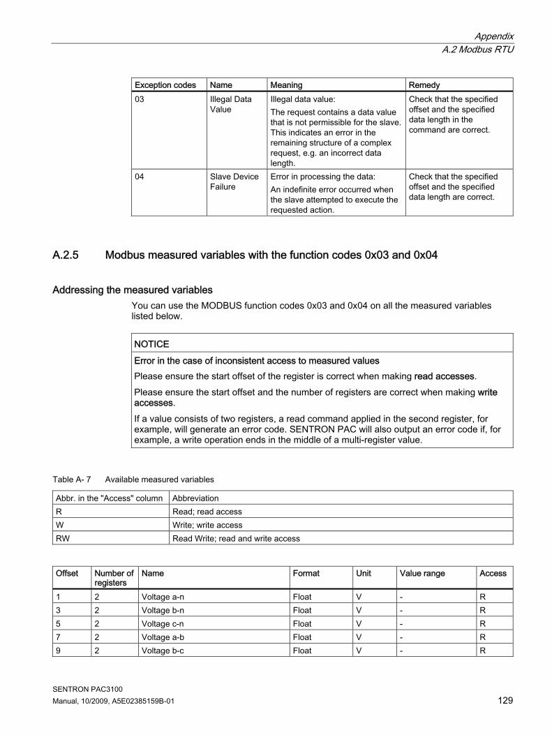
Appendix A.2 Modbus RTU
SENTRON PAC3100 Manual, 10/2009, A5E02385159B-01 129
Exception codes Name Meaning Remedy 03 Illegal Data
Value Illegal data value: The request contains a data value that is not permissible for the slave. This indicates an error in the remaining structure of a complex request, e.g. an incorrect data length.
Check that the specified offset and the specified data length in the command are correct.
04 Slave Device Failure
Error in processing the data: An indefinite error occurred when the slave attempted to execute the requested action.
Check that the specified offset and the specified data length are correct.
A.2.5 Modbus measured variables with the function codes 0x03 and 0x04
Addressing the measured variables You can use the MODBUS function codes 0x03 and 0x04 on all the measured variables listed below.
NOTICE Error in the case of inconsistent access to measured values Please ensure the start offset of the register is correct when making read accesses. Please ensure the start offset and the number of registers are correct when making write accesses. If a value consists of two registers, a read command applied in the second register, for example, will generate an error code. SENTRON PAC will also output an error code if, for example, a write operation ends in the middle of a multi-register value.
Table A- 7 Available measured variables
Abbr. in the "Access" column Abbreviation R Read; read access W Write; write access RW Read Write; read and write access
Offset Number of
registers Name Format Unit Value range Access
1 2 Voltage a-n Float V - R 3 2 Voltage b-n Float V - R 5 2 Voltage c-n Float V - R 7 2 Voltage a-b Float V - R 9 2 Voltage b-c Float V - R

Appendix A.2 Modbus RTU
SENTRON PAC3100 130 Manual, 10/2009, A5E02385159B-01
Offset Number of registers
Name Format Unit Value range Access
11 2 Voltage c-a Float V - R 13 2 Current a Float A - R 15 2 Current b Float A - R 17 2 Current c Float A - R 19 2 Apparent power a Float VA - R 21 2 Apparent power b Float VA - R 23 2 Apparent power c Float VA - R 25 2 Active power a Float W - R 27 2 Active power b Float W - R 29 2 Active power c Float W - R 31 2 Reactive power a (VAR1) Float var - R 33 2 Reactive power b (VAR1) Float var - R 35 2 Reactive power c (VAR1) Float var - R 37 2 Neutral current Float A - R 39 2 Frequency Float Hz 45 ... 65 R 47 2 Total apparent power Float VA - R 49 2 Total active power Float W - R 51 2 Total reactive power (VAR1) Float var - R 53 2 Total power factor Float - R 55 2 Maximum voltage a-n Float V - R 57 2 Maximum voltage b-n Float V - R 59 2 Maximum voltage c-n Float V - R 61 2 Max. voltage a-b Float V - R 63 2 Max. voltage b-c Float V - R 65 2 Max. voltage c-a Float V - R 67 2 Maximum current a Float A - R 69 2 Maximum current b Float A - R 71 2 Maximum current c Float A - R 73 2 Maximum apparent power a Float VA - R 75 2 Maximum apparent power b Float VA - R 77 2 Maximum apparent power c Float VA - R 79 2 Maximum active power a Float W - R 81 2 Maximum active power b Float W - R 83 2 Maximum active power c Float W - R 85 2 Max. reactive power a (VAR1) Float var - R 87 2 Max. reactive power b (VAR1) Float var - R 89 2 Max. reactive power c (VAR1) Float var - R 91 2 Max. neutral current Float A - R 93 2 Max. frequency Float Hz 45 ... 65 R 101 2 Max. total apparent power Float VA - R 103 2 Max. total active power Float W - R

Appendix A.2 Modbus RTU
SENTRON PAC3100 Manual, 10/2009, A5E02385159B-01 131
Offset Number of registers
Name Format Unit Value range Access
105 2 Max. total reactive power (VAR1) Float var - R 107 2 Max. total power factor Float - R 109 2 Minimum voltage a-n Float V - R 111 2 Minimum voltage b-n Float V - R 113 2 Minimum voltage c-n Float V - R 115 2 Min. voltage a-b Float V - R 117 2 Min. voltage b-c Float V - R 119 2 Min. voltage c-a Float V - R 121 2 Minimum current a Float A - R 123 2 Minimum current b Float A - R 125 2 Minimum current c Float A - R 127 2 Minimum apparent power a Float VA - R 129 2 Minimum apparent power b Float VA - R 131 2 Minimum apparent power c Float VA - R 133 2 Minimum active power a Float W - R 135 2 Minimum active power b Float W - R 137 2 Minimum active power c Float W - R 139 2 Min. reactive power a (VAR1) Float var - R 141 2 Min. reactive power b (VAR1) Float var - R 143 2 Min. reactive power c (VAR1) Float var - R 145 2 Min. neutral current Float A - R 147 2 Min. frequency Float Hz 45 ... 65 R 155 2 Min. total apparent power Float VA - R 157 2 Min. total active power Float W - R 159 2 Min. total reactive power (VAR1) Float var - R 161 2 Min. total power factor Float - R 205 2 Device diagnostics and device status* Unsigned long - Byte 1 system
status R
207 2 Status of the digital outputs* Unsigned long - Byte 3 Bit 0 = output 0 Bit 1 = output 1
R
209 2 Status of the digital inputs* Unsigned long - Byte 3 Bit 0 = input 0 Bit 1 = input 1
R
217 2 Relevant parameter changes counter Unsigned long - - R 219 2 Counter all parameter changes Unsigned long - - R 501 2 Cumulated active power import in the
current period Float W - R
503 2 Cumulated reactive power import in the current period
Float var - R
505 2 Cumulated active power export in the current period
Float W - R
507 2 Cumulated reactive power export in the current period
Float var - R

Appendix A.2 Modbus RTU
SENTRON PAC3100 132 Manual, 10/2009, A5E02385159B-01
Offset Number of registers
Name Format Unit Value range Access
509 2 Maximum active power in the current period
Float W - R
511 2 Minimum active power in the current period
Float W - R
513 2 Maximum reactive power in the current period
Float var - R
515 2 Minimum reactive power in the current period
Float var - R
517 2 Length of the current period Unsigned long s - R 519 2 Time since the start of the
instantaneous period Unsigned long s - R
801 4 Active energy (import, export, balance) Double Wh Overflow 1.0e+12 RW 805 4 Reactive energy (import, export,
balance) Double varh Overflow 1.0e+12 RW
A.2.6 Structure - Digital input status and digital output status with the function codes 0x03 and 0x04
The following are available via MODBUS: ● "Status of the Digital Inputs" ● "Status of the Digital Outputs"
Input status and output status of the SENTRON PAC Power Monitoring Device
Table A- 8 Structure - Status of the digital inputs and outputs, Modbus Offset 207 and 209
Name Length Status Byte Bit Bit mask Access Status: Digital output 0 32 bits DO 3 0 0x00000001 R Status: Digital output 1 32 bits DO 3 1 0x00000010 R Status: Digital input 0 32 bits DI 3 0 0x00000001 R Status: Digital input 1 32 bits DI 3 1 0x00000010 R
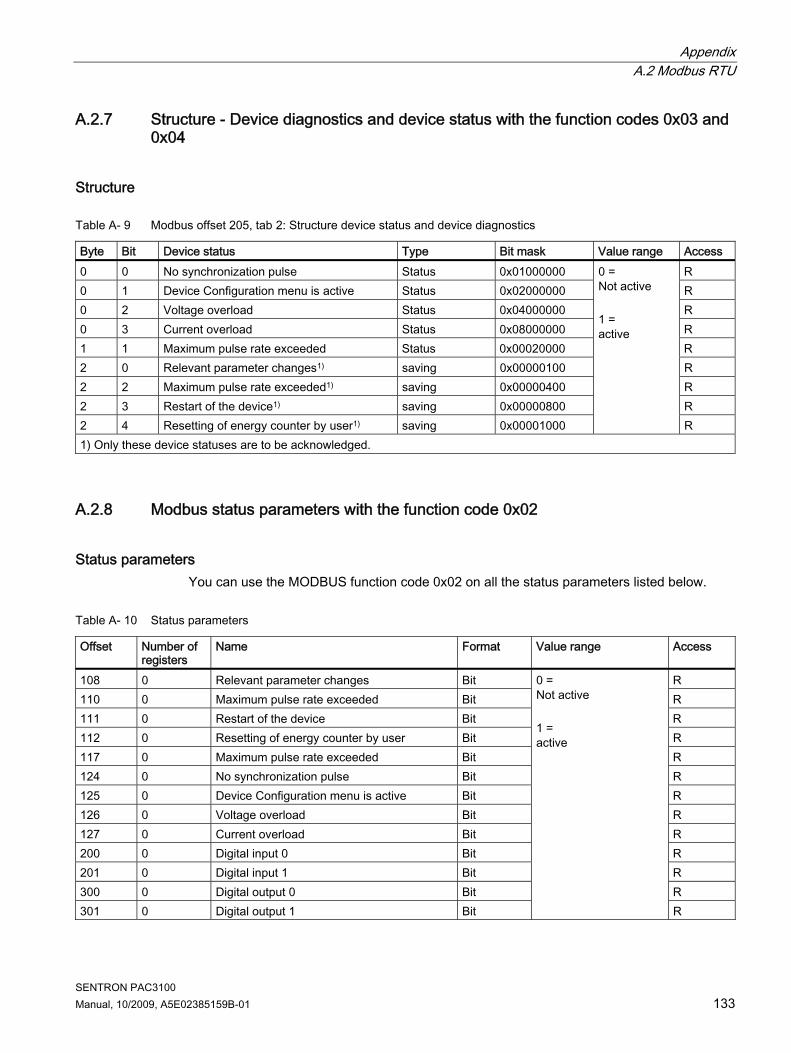
Appendix A.2 Modbus RTU
SENTRON PAC3100 Manual, 10/2009, A5E02385159B-01 133
A.2.7 Structure - Device diagnostics and device status with the function codes 0x03 and 0x04
Structure
Table A- 9 Modbus offset 205, tab 2: Structure device status and device diagnostics
Byte Bit Device status Type Bit mask Value range Access 0 0 No synchronization pulse Status 0x01000000 R 0 1 Device Configuration menu is active Status 0x02000000 R 0 2 Voltage overload Status 0x04000000 R 0 3 Current overload Status 0x08000000 R 1 1 Maximum pulse rate exceeded Status 0x00020000 R 2 0 Relevant parameter changes1) saving 0x00000100 R 2 2 Maximum pulse rate exceeded1) saving 0x00000400 R 2 3 Restart of the device1) saving 0x00000800 R 2 4 Resetting of energy counter by user1) saving 0x00001000
0 = Not active 1 = active
R 1) Only these device statuses are to be acknowledged.
A.2.8 Modbus status parameters with the function code 0x02
Status parameters You can use the MODBUS function code 0x02 on all the status parameters listed below.
Table A- 10 Status parameters
Offset Number of registers
Name Format Value range Access
108 0 Relevant parameter changes Bit R 110 0 Maximum pulse rate exceeded Bit R 111 0 Restart of the device Bit R 112 0 Resetting of energy counter by user Bit R 117 0 Maximum pulse rate exceeded Bit R 124 0 No synchronization pulse Bit R 125 0 Device Configuration menu is active Bit R 126 0 Voltage overload Bit R 127 0 Current overload Bit R 200 0 Digital input 0 Bit R 201 0 Digital input 1 Bit R 300 0 Digital output 0 Bit R 301 0 Digital output 1 Bit
0 = Not active 1 = active
R

Appendix A.2 Modbus RTU
SENTRON PAC3100 134 Manual, 10/2009, A5E02385159B-01
A.2.9 Modbus settings with the function codes 0x03, 0x04 and 0x10
Addressing the settings You can use the MODBUS function codes 0x03, 0x04 for read accesses and 0x10 for write accesses on all the settings parameters listed below.
Table A- 11 Settings parameters
Offset Number of registers
Name Unit Format Value range Access
0 = 3P4W 50001 2 Connection type - unsigned long 1 = 3P3W
RW
0 = No 50003 2 Voltage measurement using voltage transformers?
- unsigned long 1 = Yes
RW
50005 2 Primary voltage - unsigned long 1 ... 999999 V RW 50007 2 Secondary voltage - unsigned long 1 ... 480 V RW 50011 2 Primary current - unsigned long 1 ... 99999 A RW 50013 2 Secondary current - unsigned long 5 A R
0 = Normal direction 1 = Inverted direction Bit 0 L1 Bit 1 L2
50019 2 Invert CT polarity by phase
- unsigned long
Bit 2 L3
RW
50021 2 Demand period Min. unsigned long 1 ... 60 RW 0 = No synchronization 50023 2 Synchronization - unsigned long 1 = Synchronization
via bus
RW
LOWORD: kWh HIWORD: kVARh 0-2 0 = Import 1 = Export
50025 2 Energy counting - unsigned long
2 = Balance
RW
Table A- 12 Settings parameter for the digital output DO 0.0
Offset Number of registers
Name Unit Format Value range Access
50033 2 DO 0.0 Vector Group Assignment
- unsigned long 0 ... 99 RW
0 = Off 1 = Remote output
50035 2 DO 0.0 Type of Use - unsigned long
2 = Energy pulse
RW
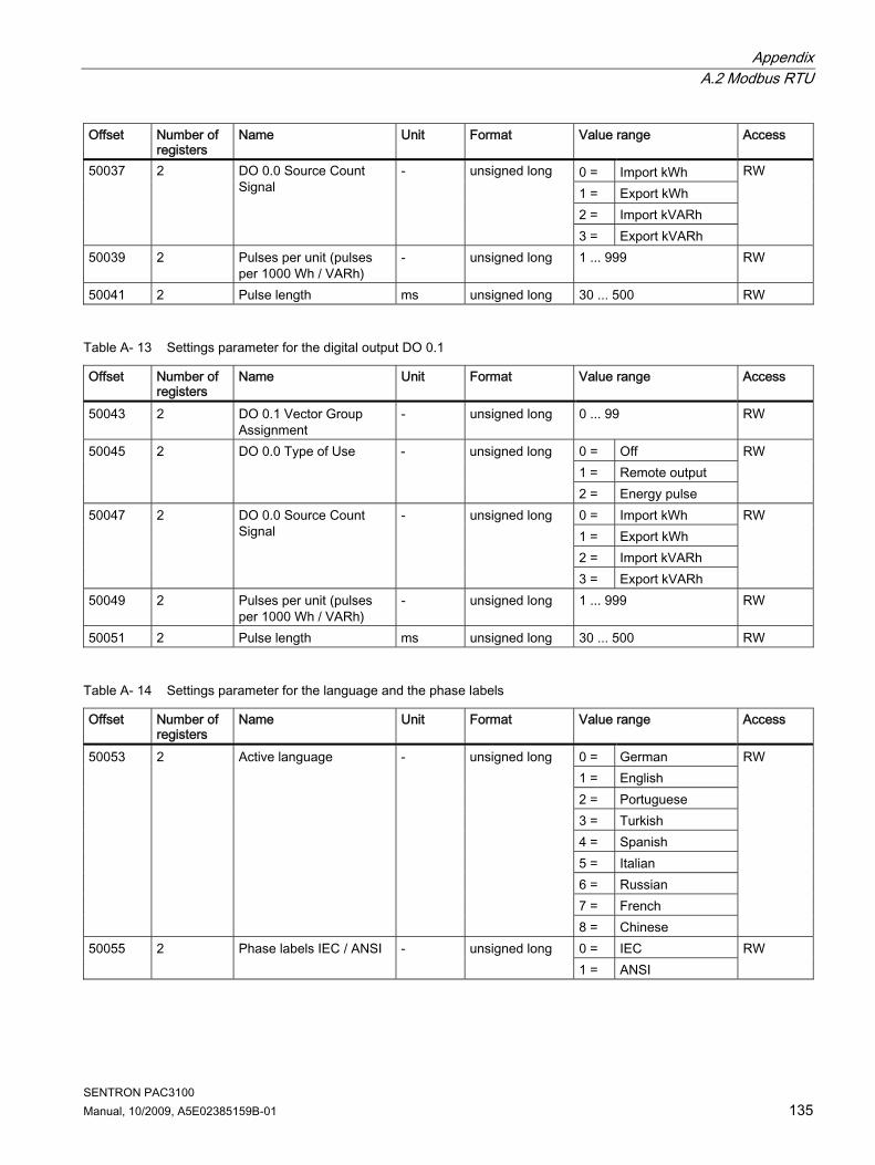
Appendix A.2 Modbus RTU
SENTRON PAC3100 Manual, 10/2009, A5E02385159B-01 135
Offset Number of registers
Name Unit Format Value range Access
0 = Import kWh 1 = Export kWh 2 = Import kVARh
50037 2 DO 0.0 Source Count Signal
- unsigned long
3 = Export kVARh
RW
50039 2 Pulses per unit (pulses per 1000 Wh / VARh)
- unsigned long 1 ... 999 RW
50041 2 Pulse length ms unsigned long 30 ... 500 RW
Table A- 13 Settings parameter for the digital output DO 0.1
Offset Number of registers
Name Unit Format Value range Access
50043 2 DO 0.1 Vector Group Assignment
- unsigned long 0 ... 99 RW
0 = Off 1 = Remote output
50045 2 DO 0.0 Type of Use - unsigned long
2 = Energy pulse
RW
0 = Import kWh 1 = Export kWh 2 = Import kVARh
50047 2 DO 0.0 Source Count Signal
- unsigned long
3 = Export kVARh
RW
50049 2 Pulses per unit (pulses per 1000 Wh / VARh)
- unsigned long 1 ... 999 RW
50051 2 Pulse length ms unsigned long 30 ... 500 RW
Table A- 14 Settings parameter for the language and the phase labels
Offset Number of registers
Name Unit Format Value range Access
0 = German 1 = English 2 = Portuguese 3 = Turkish 4 = Spanish 5 = Italian 6 = Russian 7 = French
50053 2 Active language - unsigned long
8 = Chinese
RW
0 = IEC 50055 2 Phase labels IEC / ANSI - unsigned long 1 = ANSI
RW

Appendix A.2 Modbus RTU
SENTRON PAC3100 136 Manual, 10/2009, A5E02385159B-01
Table A- 15 Settings parameter for the display
Offset Number of registers
Name Unit Format Value range Access
50057 2 Refresh time ms unsigned long 330 ... 3000 RW 50059 2 Contrast - unsigned long 0 ... 10 RW
0 = OFF 50061 2 Lighting - unsigned long 1 = ON
RW
50065 2 Lighting duration until automatic shutdown
Min. unsigned long 0 ... 99 0 = no shutdown
RW
A.2.10 MODBUS communication parameter with the function codes 0x03, 0x04 and 0x10
Addressing the communication parameters
Table A- 16 Communication parameters
Offset Number of registers
Name Unit Format Applicable MODBUS function codes
Value range from ... to
Access
63007 2 Bootloader version - unsigned long • 0x03 • 0x04
char, uchar, uchar, uchar
R
63009 2 Password protection ON/OFF
- unsigned long • 0x03 • 0x04
0, 1 R
63019 2 MODBUS address - unsigned long • 0x03 • 0x04 • 0x10
1 ... 247 RW
63021 2 Baud rate - unsigned long • 0x03 • 0x04 • 0x10
0 = 4,800 baud 1 = 9,600 baud 2 = 19,200 baud 3 = 38,400 baud
RW
0 = 8N2 1 = 8E1 2 = 8O1
63023 2 Data bits / Parity bits / Stop bits
- unsigned long • 0x03 • 0x04 • 0x10
3 = 8N1
RW
63025 2 Response time ms unsigned long • 0x03 • 0x04 • 0x10
0 ... 255 0 = Auto
RW

Appendix A.2 Modbus RTU
SENTRON PAC3100 Manual, 10/2009, A5E02385159B-01 137
A.2.11 Modbus device information with the function codes 0x03, 0x04 and 0x10
Addressing the device information parameters You access the following device information parameters block-by-block only, e.g. read from Offset 64001 27 Register.
NOTICE Error in the case of inconsistent access to I&M data Please ensure the start offset and the number of registers are correct when making read accesses and write accesses. Always read or write the entire block. Please ensure the start offset and the number of registers are correct when making write accesses. If a value consists of several registers, a read command applied in the second register, for example, will generate an error code. SENTRON PAC will also output an error code if, for example, a write operation ends in the middle of a multi-register value.
Table A- 17 I&M 0 parameters with the function codes 0x03 and 0x04
Offset Total registers
Number of registers per parameter
Name Format Value range from ... to
Access
Start offset 64001
[1] Manufacturer's ID unsigned short 42*) R
[64002] [10] Order No. Char 20 ASCII R [64012] [8] Serial number Char 16 ASCII R [64020] [1] Hardware version unsigned short 0 ... 65535 R [64021] [2] Firmware version 1 char, 3 unsigned
char V 0.0.0 ... V 255.255.255
R
[64023] [1] Counter for changes unsigned short 1 ... 65535 R [64024] [1] Profile ID unsigned short 3A00 ... F6FF R [64025] [1] Specific Profile ID unsigned short - R [64026] [1] Version of the I&M data 2 unsigned char 0.0 ... 255.255 R [64027]
27
[1] Supported I&M data unsigned short 00 ... FF R *) 42 stands for Siemens AG

Appendix A.2 Modbus RTU
SENTRON PAC3100 138 Manual, 10/2009, A5E02385159B-01
Table A- 18 I&M 1-4 parameters with the function codes 0x03, 0x04 and 0x10
Offset Total registers
Number of registers per parameter
Name Format Value range from ... to
Access
Start offset 64028
[16] Plant identifier Char 32 ASCII RW
[64044] [11] Location identifier Char 22 ASCII RW [64055] [8] Installation date Char 16 ASCII RW [64063] [27] Comment Char 54 ASCII RW [64090]
89
[27] Signature Char 54 - RW
A.2.12 Modbus command parameters
Addressing the command parameters You can use MODBUS function code 0x06 on the command parameters.
Table A- 19 Command parameters
Offset Number of registers
Name Unit Format Value range from ... to Access
60000 1 Reset the device to the factory settings
- unsigned short - W
60001 1 Device reset (without changing the Modbus address)
- unsigned short - W
60002 1 Reset maximum values - unsigned short 0 W 60003 1 Reset minimum values - unsigned short 0 W
0 = All 1 = Imported active energy 2 = Exported active energy 3 = Imported reactive energy
60004 1 Reset energy counter - unsigned short
4 = Exported reactive energy
W
60005 1 Synchronization of the demand period
Min. unsigned short 1 ... 60 W
60007 1 Acknowledge the diagnostics bit1) (cf. stored bits in unsigned long beginning offset 205)
- unsigned short 0 ... ffffh W
0ffh ... 1ffh Byte 0 = 0 Digital output 0.0 Byte 0 = 1 Digital output 0.1 Byte 1 = 0 OFF
60008 1 Switching outputs (if parameterized)
- unsigned short
Byte 1 = 1 ON
W

Appendix A.3 Correction sheet
SENTRON PAC3100 Manual, 10/2009, A5E02385159B-01 139
Offset Number of registers
Name Unit Format Value range from ... to Access
60009 1 Switching command for vector group
- unsigned short High 0 ... 99, Low 0 ... 1 High byte group assignment Low byte 1 = ON, 0 = OFF
W
1) The MODBUS master must acknowledge these diagnostics bits.
A.2.13 MODBUS standard device identification with the function code 0x2B
Addressing the MODBUS standard device identification You can use MODBUS function code 0x2B on these device identification parameters.
Table A- 20 MODBUS standard device identification parameters
Object ID Name Format Access OID 0 Manufacturer String R OID 1 Manufacturer device name String R OID 2 Firmware version / bootloader version String R
A.3 Correction sheet
Correction sheet Have you noticed any errors while reading this manual? If so, please use this form to tell us about them. We welcome comments and suggestions for improvement.

Appendix A.3 Correction sheet
SENTRON PAC3100 140 Manual, 10/2009, A5E02385159B-01
Fax response From (please complete): To SIEMENS AG I IA CD MM 3 92220 Amberg / Germany
Name Company/Department Address
_________________________________________________________________________________ Fax: +49 (0)9621-80-3337 Manual title:
Table A- 21 Errors, comments, and suggestions for improvements

SENTRON PAC3100 Manual, 10/2009, A5E02385159B-01 141
ESD guidelines BB.1 Electrostatic sensitive devices (ESD)
ESD components are destroyed by voltage and energy far below the limits of human perception. Voltages of this kind occur as soon as a device or an assembly is touched by a person who is not electrostatically discharged. ESD components which have been subject to such voltage are usually not recognized immediately as being defective, because the malfunction does not occur until after a longer period of operation.
ESD guidelines
CAUTION Electrostatic sensitive devices Electronic modules contain components that can be destroyed by electrostatic discharge. These modules can be easily destroyed or damaged by improper handling. • You must discharge your body electrostatically immediately before touching an
electronic component. To do this, touch a conductive, grounded object, e.g., a bare metal part of a switch cabinet or the water pipe.
• Always hold the component by the plastic enclosure. • Electronic modules should not be brought into contact with electrically insulating
materials such as plastic film, plastic parts, insulating table supports or clothing made of synthetic fibers.
• Always place electrostatic sensitive devices on conductive bases. • Always store and transport electronic modules or components in ESD-safe conductive
packaging, e.g. metallized plastic or metal containers. Leave the component in its packaging until installation.
CAUTION Storage and transport If you have to store or transport the component in non-conductive packaging, you must first pack the component in ESD-safe, conductive material, e.g., conductive foam rubber, ESD bag.
The diagrams below illustrate the required ESD protective measures for electrostatic sensitive devices.

ESD guidelines B.1 Electrostatic sensitive devices (ESD)
SENTRON PAC3100 142 Manual, 10/2009, A5E02385159B-01
(1) ESD seat (2) ESD standing position (3) ESD seat and ESD standing position Protective measures a Conductive floor b ESD table c ESD footwear d ESD smock e ESD bracelet f Cubicle ground connection

SENTRON PAC3100 Manual, 10/2009, A5E02385159B-01 143
List of abbreviations CC.1 Abbreviations
Overview
Table C- 1 Meaning of abbreviations
Abbreviation Meaning AWG American Wire Gauge CE Communautés Européennes (French for "European Union") CISPR Comité international spécial des perturbations radioélectriques CSA Canadian Standards Association DIN Deutsches Institut für Normierung e. V. EC European Union ESD Electrostatic sensitive devices EIA Electronic Industries Alliance EMC Electromagnetic compatibility EN European Standard EU European Union FCC Federal Communications Commission I&M Information and Maintenance ID Identification number IEC International Electrotechnical Commission IP International Protection ISM Industrial, Scientific and Medical ISO International Standardization Organization LCD Liquid crystal display LED Light Emitting Diode NAFTA North American Free Trade Agreement NEMA National Electrical Manufacturers Association PAC Power Analysis & Control PMD Power Monitoring Device RS Formerly: Radio Selector; now usually: Recommended Standard TCP/IP Transmission Control Protocol/Internet Protocol TRMS True Root Mean Square UL Underwriters Laboratories Inc. VDE Association of Electrical Engineering, Electronics and Information Technology
(Germany)

List of abbreviations C.1 Abbreviations
SENTRON PAC3100 144 Manual, 10/2009, A5E02385159B-01

SENTRON PAC3100 Manual, 10/2009, A5E02385159B-01 145
Glossary
American Wire Gauge American Wire Gauge is a number assigned to a specific conductor or wire cross-section.
Balance The SENTRON PAC3100 calculates the energy balance for active energy and reactive energy. Balance equals import minus export.
Baud rate The baud rate is the rate of data transmission. It indicates the number of bits transferred in one second.
Modbus RTU Modbus RTU is a master/slave protocol which runs on a serial channel. On a Modbus RTU bus, only one device can assume the function of the bus master.

Glossary
SENTRON PAC3100 146 Manual, 10/2009, A5E02385159B-01

SENTRON PAC3100 Manual, 10/2009, A5E02385159B-01 147
Index
A Applying the measuring current, 61 Applying the measuring voltage, 61 Applying the supply voltage, 52 Approvals, 112
B Basic Device Identification, 128 Basic parameters
Parameterizing, 85 Bit mask, 132, 133
C CE conformity, 112 Character frame, 126 Check the packaging, 31 Circuit breaker, 30 Cleaning, 101 Clearance measurements, 116 Clearances, 117 Command parameters, 138 Communication, 26, 48, 107
Status, 27 Communication parameters, 91, 136 Components of the product, 12 Conductive floor, 142 Connection
RS 485 interface, 48 Connection elements, 108 Connection examples, 45 Connection type
Checking, 62 Dependency of the measured variables, 18 setting, 55
Connection types, 18 Correction sheet, 139 Counters, 16, 22 CRC, 125 Cubicle ground connection, 142 Current direction, 20 Current input
Parameterizing, 87 Current transformers
Set the conversion ratio, 59 Cyclic Redundancy Check, 125
D Default password, 95 Degree of protection, 111 Deinstallation, 37 Device diagnostics, 133 Device identification parameters, 139 Device information
Parameterizing, 84 Device status, 133 Device versions, 15 Digital input, 23
Parameterizing, 91 Digital output, 24
Parameterizing, 90 Dimensions, 115
Clearance measurements, 116 Clearances, 117 Frame dimensions, 116 Panel cutout, 115
Direction of current flow, 62 Discharge, 141 Display
Contrast, 92 Device setting, 92 Display, 92 Lighting, 92 Measured variables depending on the connection type, 18 Parameterizing, 92 Refresh rate, 92
Disposal, 103
E Electrostatic sensitive devices, 141 End of message frame, 125 Energy counters, 22
Parameterizing, 89 Environmental conditions, 30, 111 Error code, 127, 129, 137 ESD bracelet, 142 ESD footwear, 142 ESD guidelines, 141

Index
SENTRON PAC3100 148 Manual, 10/2009, A5E02385159B-01
ESD protective measures, 141 ESD seat, 142 ESD smock, 142 ESD standing position, 142 ESD table, 142 Exception code, 127, 128
F Factory defaults, 94 Features, 15 Firmware updates, 101 Frame dimensions, 116 Function code, 126, 139
G General safety notes, 13
I Installation format, 16 Installation space
Ventilation, 29 Installation tools, 32 Integrated I/Os
Parameterizing, 89 Interface, 16
J Job message frame, 125
L Language, 54
Parameterizing, 85 LED, 27 LSB, 125, 126
M Master, 125 Measured value acquisition, 105 Measured variables, 119
Display, 18 Measuring method, 105 MEI, 128 Modbus
Digital inputs, status, 132 Digital outputs, status, 132
MODBUS Exception codes, 128
MODBUS Encapsulated Interface, 128 MODBUS function code, 129, 133, 134, 136, 138, 139 MODBUS measured variables, 129 Modbus RTU, 26, 48, 60, 95, 107
Communication parameters, 91 More information
SENTRON PAC3100, 12 Mounting
Procedure, 32 Mounting dimensions, 115 Mounting location, 29 Mounting position, 29 MSB, 125, 126
O Object ID, 139 Offset, 129, 133, 134, 135, 136, 138 Orientation aids, 11 Overload display, 19
P Packaging, 31 Panel cutout
Dimensions, 115 Parameter
Command, 138 Communication, 136 Device information, 139 Status, 133
Parameterizing Basic parameters, 85 Current input, 87 Device information, 84 Device settings, 83 Digital input, 91 Digital output, 90 Display, 92 Energy counters, 89 Integrated I/Os, 89 Language, 85 Password, 94 Power demand, 88 Regional settings, 85 RS 485 interface, 91 Startup, 53

Index
SENTRON PAC3100 Manual, 10/2009, A5E02385159B-01 149
Voltage input, 86 Parameterizing the device, 53 Password
Administration, 95 Default password, 95 lost, forgotten, 99 Parameterizing, 94
Power demand, 16, 21 Parameterizing, 88
Power failure, 23 Power supply, 16 Prerequisites
Startup, 51 Procedure
Mounting, 32 Protection, 17 Protection class, 111
R Read Device Identification, 128 Recycling, 103 Regional settings
Parameterizing, 85 Register, 128, 129, 133, 134, 135, 136, 138 Repair, 102
Loss of warranty, 102 Required basic knowledge, 11 Reset, 94 RS 485, 60, 110 RS 485 interface, 26, 48, 107
Parameterizing, 91
S Safety regulations, 112 Screw terminal, 108
RS 485, 110 Technical data, 109
SENTRON PAC3100 More information, 12
Setting the language, 54 Setting the voltage input, 58 Slave, 125 Startup, 51
Applying the supply voltage, 52 Parameterizing the device, 53 Prerequisites, 51 Setting the connection type, 55 Setting the language, 54
Status display, 27
Status parameters, 133 Storage, 31, 141 String, 128 Structure of the message frame, 125
T Technical data, 105
Communication, 107 Connection elements, 108 Degree of protection, 111 Digital inputs, 107 Digital outputs, 107 Display, 108 Environmental conditions, 111 Measured value acquisition, 105 Measuring accuracy, 106 Measuring inputs, 105, 106 Measuring method, 105 Power supply, 106 Protection class, 111 RS 485 interface, 107 Safety regulations, 112 Screw terminal, 108
Temperature compensation, 30 Terminal labeling, 42 Transport, 141 Turn-off time, 25
U Updating the firmware, 101
V Validity range, 11 Ventilation
Installation space, 29 Voltage input, 58
Parameterizing, 86 Voltage transformers
Measurement, 56 Set the conversion ratio, 57

Index
SENTRON PAC3100 150 Manual, 10/2009, A5E02385159B-01