Embed Size (px)
Citation preview
Manual, Robotic Tool Changer, QC‑40Document #9620‑20‑B‑40Q Series Base Tool Changer‑06
Pinnacle Park • 1031 Goodworth Drive • Apex, NC 27539 • Tel: 919.772.0115 • Fax: 919.772.8259 • www.ati‑ia.com • Email: info@ati‑ia.com B-1
Table of ContentsB. Base Tool Changer .................................................................................................................B-3QC-40Q Series—Robotic Tool Changer .....................................................................................B-31. Product Overview ..................................................................................................................B-3
1.1 Master Plate Assembly ............................................................................................................. B-3
1.2 Tool Plate Assembly .................................................................................................................. B-4
1.3 Optional Modules ...................................................................................................................... B-4
2. Installation .............................................................................................................................B-52.1 Master Interface ......................................................................................................................... B-6
2.2 Master Plate Installation ........................................................................................................... B-7
2.3 Master Plate Removal ............................................................................................................... B-8
2.4 Tool Interface ............................................................................................................................. B-9
2.5 Tool Plate Installation ............................................................................................................. B-10
2.6 Tool Plate Removal ................................................................................................................. B-10
2.7 Pneumatic Connections ..........................................................................................................B-112.7.1 Valve Requirements and Connections for the Locking Mechanism ..............................B-11
2.8 Installing Optional Modules ................................................................................................... B-122.8.1 Optional Module Installation ..........................................................................................B-12
2.8.2 Optional Module Removal .............................................................................................B-12
2.9 Electrical Connections ............................................................................................................ B-132.9.1 PNP Type Lock and Unlock Sensors (-SB, -SD, -SG sensor designations) ..................B-13
2.9.2 NPN Type Lock and Unlock Sensors (-SA, -SE, -SF sensor designations) ..................B-13
3. Operation .............................................................................................................................B-143.1 Conditions for Coupling ......................................................................................................... B-15
3.2 Fail-Safe Operation ................................................................................................................. B-15
3.3 Conditions for Uncoupling ..................................................................................................... B-16
3.4 Tool Storage Considerations ................................................................................................. B-16
4. Maintenance .........................................................................................................................B-174.1 Preventive Maintenance ......................................................................................................... B-17
4.2 Cleaning and Lubrication of the Locking Mechanism and Alignment Pins ....................... B-18
4.3 Pin Block Inspection and Cleaning ....................................................................................... B-20
5. Troubleshooting and Service Procedures ........................................................................B-215.1 Troubleshooting Procedures ................................................................................................. B-21
5.2 Service Procedures ................................................................................................................. B-225.2.1 V-ring Seal Replacement ...............................................................................................B-22
5.2.2 Lock and Unlock Sensor Assembly Replacement .........................................................B-23

Manual, Robotic Tool Changer, QC‑40Document #9620‑20‑B‑40Q Series Base Tool Changer‑06
Pinnacle Park • 1031 Goodworth Drive • Apex, NC 27539 • Tel: 919.772.0115 • Fax: 919.772.8259 • www.ati‑ia.com • Email: info@ati‑ia.com B-3
6. Serviceable Parts ................................................................................................................B-246.1 Model 9120-040QM-000-000-S0 .............................................................................................. B-24
6.2 Model 9120-040QM-000-000-S0-E .......................................................................................... B-25
6.3 Model 9120-040QM-000-000-SA and 9120-040QM-000-000-SB............................................ B-26
6.4 Model 9120-040QM-000-000-SA-E and 9120-040QM-000-000-SB-E .................................... B-27
6.5 Model 9120-040QM-000-000-SD and 9120-040QM-000-000-SF ............................................ B-28
6.6 Model 9120-040QM-000-000-SD-E and 9120-040QM-000-000-SF-E ..................................... B-29
6.7 Model 9120-040QM-000-000-SE and 9120-040QM-000-000-SG ........................................... B-30
6.8 Model 9120-040QM-000-000-SE-E and 9120-040QM-000-000-SG-E .................................... B-31
6.9 Standard Tool Plate ................................................................................................................ B-32
6.10 Euro Tool Plate ....................................................................................................................... B-32
7. Specifications ......................................................................................................................B-338. Drawings ..............................................................................................................................B-34
8.1 QC-40Q Tool Changer ............................................................................................................. B-34

Manual, Robotic Tool Changer, QC‑40Document #9620‑20‑B‑40Q Series Base Tool Changer‑06
Pinnacle Park • 1031 Goodworth Drive • Apex, NC 27539 • Tel: 919.772.0115 • Fax: 919.772.8259 • www.ati‑ia.com • Email: info@ati‑ia.com B-3
B. Base Tool Changer
QC-40Q Series—Robotic Tool Changer1. Product Overview
ATI Tool Changers enhance the versatility of a robot by enabling the use of multiple customer tools, such as grippers, vacuum cup tooling, pneumatic and electric motors, weld guns, and more.
The Tool Changer consists of a Master plate, which is attached to the robot arm, and a Tool plate, which is attached to customer tooling. When the robot picks up the customer tooling, a pneumatically‑driven locking mechanism couples the two plates. The patented, fail‑safe locking mechanism utilizes a multi‑tapered cam with ball locking technology to ensure the Tool Changer does not uncouple if air pressure falls below 60 psi (4.1 bar) during operation.
The robot can be programmed to select the desired customer tooling by coupling the Master plate to the Tool plate. Electrical, fluid, and other utilities transfer to the customer tooling through optional modules that are attached to the Master and Tool plates. Refer to the ATI website for compatible modules or contact an ATI sales representative for more details.
For the most current product information and specifications on the QC‑40Q Series of Tool Changers, visit the following ATI web page: http://www.ati‑ia.com/products/toolchanger/QC.aspx?ID=QC‑40Q
1.1 Master Plate AssemblyThe Master plate assembly includes:• Anodized aluminum body
• Hardened stainless steel locking mechanism
• Hardened steel alignment pins (see Figure 1.1)
• (2) flat sides for mounting optional modules with J16 mounting pattern
• (2) 1/8 NPT connections supply pneumatic pressure for coupling and uncoupling the Tool Changer
• (8) 1/8 NPT connections for passing air or vacuum through the Tool Changer
• Proximity sensors to verify the lock/unlock position of the piston and cam and provide lock and unlock (L/U) signals through the sensor cables provided.
Figure 1.1—Master Plate Assembly
Lock Port(1/8 NPT)
Unlock Port(1/8 NPT)
Lock/Unlock Sensor Assemblies
(6) Ball Bearing
(2) Alignment Pin
Male Coupling(8) Pass Through Air/Vacuum Port(1/8 NPT)
Flat B for Optional Modules
Flat A for Optional Modules
Cam
Manual, Robotic Tool Changer, QC‑40Document #9620‑20‑B‑40Q Series Base Tool Changer‑06
Pinnacle Park • 1031 Goodworth Drive • Apex, NC 27539 • Tel: 919.772.0115 • Fax: 919.772.8259 • www.ati‑ia.com • Email: info@ati‑ia.com B-4
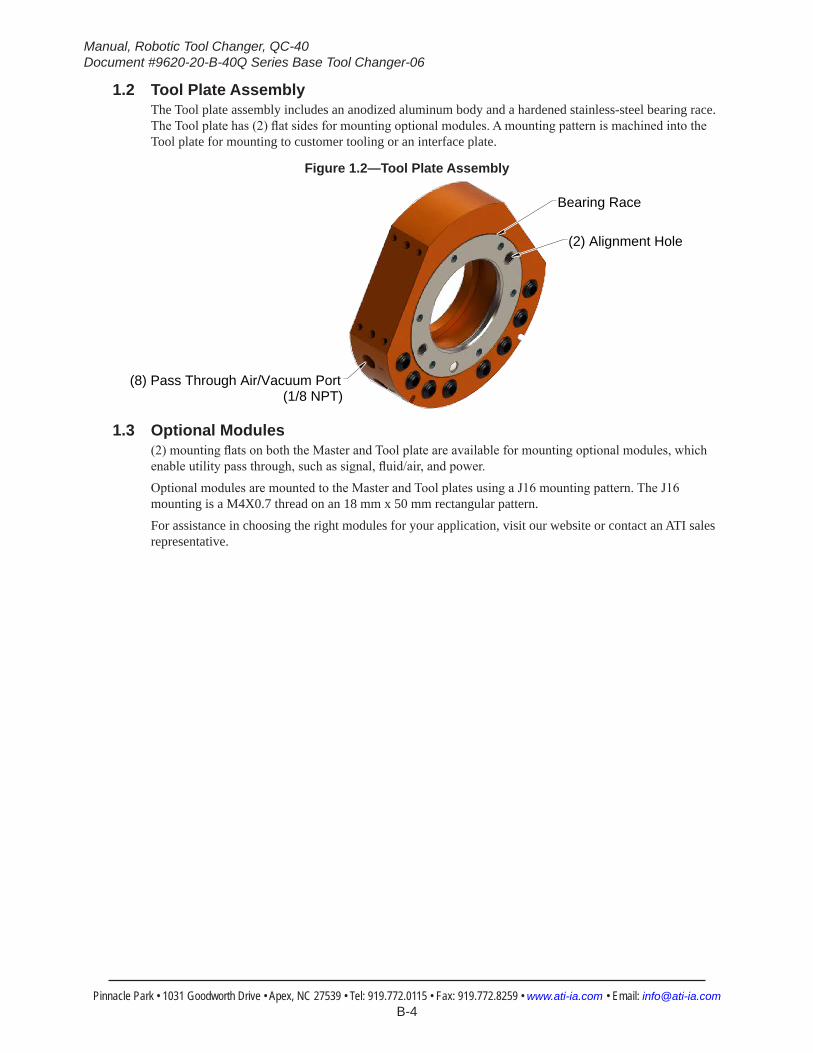
1.2 Tool Plate AssemblyThe Tool plate assembly includes an anodized aluminum body and a hardened stainless‑steel bearing race. The Tool plate has (2) flat sides for mounting optional modules. A mounting pattern is machined into the Tool plate for mounting to customer tooling or an interface plate.
Figure 1.2—Tool Plate Assembly
Bearing Race
(2) Alignment Hole
(8) Pass Through Air/Vacuum Port(1/8 NPT)
1.3 Optional Modules(2) mounting flats on both the Master and Tool plate are available for mounting optional modules, which enable utility pass through, such as signal, fluid/air, and power.Optional modules are mounted to the Master and Tool plates using a J16 mounting pattern. The J16 mounting is a M4X0.7 thread on an 18 mm x 50 mm rectangular pattern.For assistance in choosing the right modules for your application, visit our website or contact an ATI sales representative.
Manual, Robotic Tool Changer, QC‑40Document #9620‑20‑B‑40Q Series Base Tool Changer‑06
Pinnacle Park • 1031 Goodworth Drive • Apex, NC 27539 • Tel: 919.772.0115 • Fax: 919.772.8259 • www.ati‑ia.com • Email: info@ati‑ia.com B-5
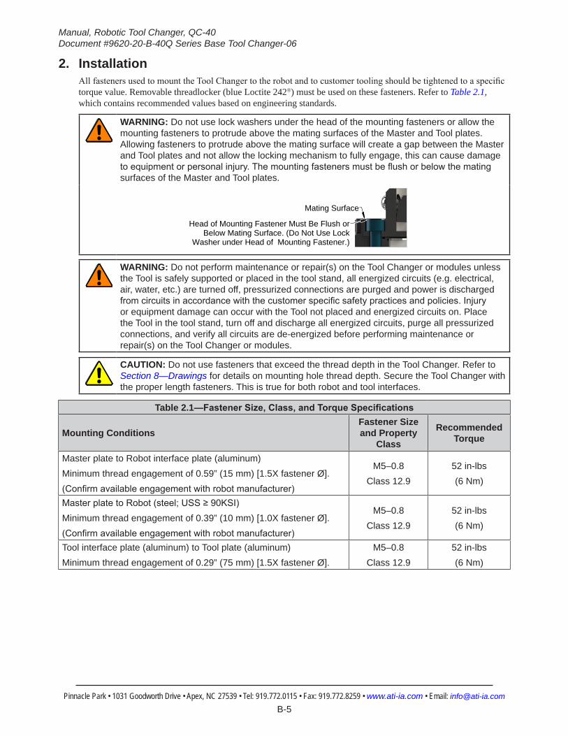
2. InstallationAll fasteners used to mount the Tool Changer to the robot and to customer tooling should be tightened to a specific torque value. Removable threadlocker (blue Loctite 242®) must be used on these fasteners. Refer to Table 2.1, which contains recommended values based on engineering standards.
WARNING: Do not use lock washers under the head of the mounting fasteners or allow the mounting fasteners to protrude above the mating surfaces of the Master and Tool plates. Allowing fasteners to protrude above the mating surface will create a gap between the Master and Tool plates and not allow the locking mechanism to fully engage, this can cause damage to equipment or personal injury. The mounting fasteners must be flush or below the mating surfaces of the Master and Tool plates.
Head of Mounting Fastener Must Be Flush orBelow Mating Surface. (Do Not Use Lock
Washer under Head of Mounting Fastener.)
Mating Surface
WARNING: Do not perform maintenance or repair(s) on the Tool Changer or modules unless the Tool is safely supported or placed in the tool stand, all energized circuits (e.g. electrical, air, water, etc.) are turned off, pressurized connections are purged and power is discharged from circuits in accordance with the customer specific safety practices and policies. Injury or equipment damage can occur with the Tool not placed and energized circuits on. Place the Tool in the tool stand, turn off and discharge all energized circuits, purge all pressurized connections, and verify all circuits are de-energized before performing maintenance or repair(s) on the Tool Changer or modules.
CAUTION: Do not use fasteners that exceed the thread depth in the Tool Changer. Refer to Section 8—Drawings for details on mounting hole thread depth. Secure the Tool Changer with the proper length fasteners. This is true for both robot and tool interfaces.
Table 2.1—FastenerSize,Class,andTorqueSpecifications
Mounting ConditionsFastener Size and Property
Class
Recommended Torque
Master plate to Robot interface plate (aluminum)Minimum thread engagement of 0.59” (15 mm) [1.5X fastener Ø]. (Confirm available engagement with robot manufacturer)
M5–0.8Class 12.9
52 in-lbs(6 Nm)
Master plate to Robot (steel; USS ≥ 90KSI)Minimum thread engagement of 0.39” (10 mm) [1.0X fastener Ø].(Confirm available engagement with robot manufacturer)
M5–0.8Class 12.9
52 in-lbs(6 Nm)
Tool interface plate (aluminum) to Tool plate (aluminum) Minimum thread engagement of 0.29” (75 mm) [1.5X fastener Ø].
M5–0.8Class 12.9
52 in-lbs(6 Nm)
Manual, Robotic Tool Changer, QC‑40Document #9620‑20‑B‑40Q Series Base Tool Changer‑06
Pinnacle Park • 1031 Goodworth Drive • Apex, NC 27539 • Tel: 919.772.0115 • Fax: 919.772.8259 • www.ati‑ia.com • Email: info@ati‑ia.com B-6
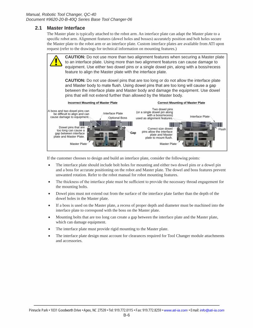
2.1 Master InterfaceThe Master plate is typically attached to the robot arm. An interface plate can adapt the Master plate to a specific robot arm. Alignment features (dowel holes and bosses) accurately position and bolt holes secure the Master plate to the robot arm or an interface plate. Custom interface plates are available from ATI upon request (refer to the drawings for technical information on mounting features.)
CAUTION: Do not use more than two alignment features when securing a Master plate to an interface plate. Using more than two alignment features can cause damage to equipment. Use either two dowel pins or a single dowel pin, along with a boss/recess feature to align the Master plate with the interface plate.
CAUTION: Do not use dowel pins that are too long or do not allow the interface plate and Master body to mate flush. Using dowel pins that are too long will cause a gap between the interface plate and Master body and damage the equipment. Use dowel pins that will not extend further than allowed by the Master body.
Master Plate
Interface Plate
Correct size dowelpins allow the interface
plate and Masterplate to mount flush.
Two dowel pins(or a single dowel pin along
with a boss/recess)used as alignment features.
Flush
Correct Mounting of Master Plate
Master Plate
Interface Plate
Dowel pins that aretoo long can cause a
plate and Master Plate.gap between interface
Optional Boss
GapGap
A boss and two dowel pins canbe difficult to align and can
cause damage to equipment.
Incorrect Mounting of Master Plate
If the customer chooses to design and build an interface plate, consider the following points:• The interface plate should include bolt holes for mounting and either two dowel pins or a dowel pin
and a boss for accurate positioning on the robot and Master plate. The dowel and boss features prevent unwanted rotation. Refer to the robot manual for robot mounting features.
• The thickness of the interface plate must be sufficient to provide the necessary thread engagement for the mounting bolts.
• Dowel pins must not extend out from the surface of the interface plate farther than the depth of the dowel holes in the Master plate.
• If a boss is used on the Master plate, a recess of proper depth and diameter must be machined into the interface plate to correspond with the boss on the Master plate.
• Mounting bolts that are too long can create a gap between the interface plate and the Master plate, which can damage equipment.
• The interface plate must provide rigid mounting to the Master plate.
• The interface plate design must account for clearances required for Tool Changer module attachments and accessories.
Manual, Robotic Tool Changer, QC‑40Document #9620‑20‑B‑40Q Series Base Tool Changer‑06
Pinnacle Park • 1031 Goodworth Drive • Apex, NC 27539 • Tel: 919.772.0115 • Fax: 919.772.8259 • www.ati‑ia.com • Email: info@ati‑ia.com B-7
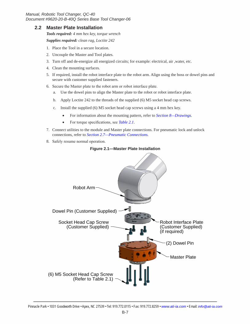
2.2 Master Plate InstallationTools required: 4 mm hex key, torque wrenchSupplies required: clean rag, Loctite 242
1. Place the Tool in a secure location.2. Uncouple the Master and Tool plates.3. Turn off and de‑energize all energized circuits; for example: electrical, air ,water, etc.4. Clean the mounting surfaces.5. If required, install the robot interface plate to the robot arm. Align using the boss or dowel pins and
secure with customer supplied fasteners.6. Secure the Master plate to the robot arm or robot interface plate.
a. Use the dowel pins to align the Master plate to the robot or robot interface plate.
b. Apply Loctite 242 to the threads of the supplied (6) M5 socket head cap screws.
c. Install the supplied (6) M5 socket head cap screws using a 4 mm hex key.
• For information about the mounting pattern, refer to Section 8—Drawings.
• For torque specifications, see Table 2.1.
7. Connect utilities to the module and Master plate connections. For pneumatic lock and unlock connections, refer to Section 2.7—Pneumatic Connections.
8. Safely resume normal operation.
Figure 2.1—Master Plate Installation
Robot Arm
Robot Interface Plate(Customer Supplied)(if required)
(6) M5 Socket Head Cap Screw (Refer to Table 2.1)
Master Plate
(2) Dowel Pin
Socket Head Cap Screw(Customer Supplied)
Dowel Pin (Customer Supplied)

Manual, Robotic Tool Changer, QC‑40Document #9620‑20‑B‑40Q Series Base Tool Changer‑06
Pinnacle Park • 1031 Goodworth Drive • Apex, NC 27539 • Tel: 919.772.0115 • Fax: 919.772.8259 • www.ati‑ia.com • Email: info@ati‑ia.com B-8
2.3 Master Plate RemovalRefer to Figure 2.1.Tools required: 4 mm hex key1. Place the Tool in a secure location.2. Uncouple the Master and Tool plates.3. Turn off and de‑energize all energized circuits; for example, electrical, air, water, etc.4. If required, disconnect all utilities.5. If equipped, disconnect the lock and unlock sensor cables.6. Disconnect the lock, unlock, and pass‑through air connections.7. While supporting the Master plate, remove the (6) M5 socket head cap screws that connect the Master
plate to the robot arm or robot interface plate using a 4 mm hex key.8. Remove the Master plate.

Manual, Robotic Tool Changer, QC‑40Document #9620‑20‑B‑40Q Series Base Tool Changer‑06
Pinnacle Park • 1031 Goodworth Drive • Apex, NC 27539 • Tel: 919.772.0115 • Fax: 919.772.8259 • www.ati‑ia.com • Email: info@ati‑ia.com B-9
2.4 Tool InterfaceThe Tool plate is attached to the customer’s tooling. An interface plate can adapt the Tool plate to customer tooling. Alignment features (dowel holes and a recess) accurately position and bolt holes to secure the Tool plate to customer tooling. Custom interface plates can be supplied by ATI (refer to the application drawing).
CAUTION: Do not use more than two alignment features when securing a Tool plate to an interface plate. Using more than two alignment features can cause damage to equipment. Use either two dowel pins or a single dowel pin, along with a boss/recess feature to align the Tool plate with the interface plate.
CAUTION: Do not use dowel pins that are too long or do not allow the interface plate and Tool body to mate flush. Using dowel pins that are too long will cause a gap between the interface plate and Tool body and damage the equipment. Use dowel pins that will not extend further than allowed by the Tool body.
Tool Plate
Interface Plate
Dowel pins areproper size allowing
interface plate and ToolPlate to mount flush.
Two dowel pins (or a
boss/recess) used asalignment features.
Correct Mounting of Tool Plate
Tool Plate
Interface Plate
Dowel pinsare too long and
cause a gap betweeninterface plate and Tool.
Boss and two dowel pinsas alignment features can be
difficult to align and candamage equipment.
Gap
Incorrect Mounting of Tool Plate
single dowel pin along with a
If the customer chooses to design and build a tool interface plate, consider the following points:• The interface plate should include bolt holes for mounting and either two dowel pins or a dowel
pin and a boss for accurate positioning on the customer tooling and Tool plate. The dowel and boss features prevent unwanted rotation.
• Dowel pins must not extend out from the surface of the interface plate farther than the depth of the dowel holes in the Tool plate.
• The thickness of the interface plate must be sufficient to provide the necessary thread engagement for the mounting bolts. Fasteners should meet minimum recommended engagement lengths while not exceeding the maximum available thread depth. Use of bolts that are too long can cause damage to the tool side changer.
• The plate design must account for clearances required for Tool Changer module attachments and accessories.
• If a boss is to be used on the interface plate, a boss of proper height and diameter must be machined into the interface plate to correspond with the recess in the Tool plate.
• The interface plate must have a hole in its center for manually returning the locking mechanism to the unlocked position under adverse conditions (i.e. unintended loss of power and/or air pressure). The center access hole with a minimum diameter of 1” (25.4 mm) prevents debris from contaminating the locking mechanism. Greater protection is provided by leaving the race cover and grommet in place.
Manual, Robotic Tool Changer, QC‑40Document #9620‑20‑B‑40Q Series Base Tool Changer‑06
Pinnacle Park • 1031 Goodworth Drive • Apex, NC 27539 • Tel: 919.772.0115 • Fax: 919.772.8259 • www.ati‑ia.com • Email: info@ati‑ia.com B-10
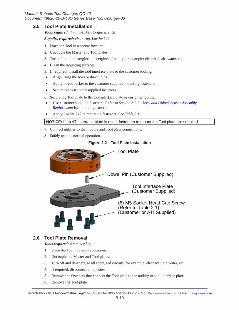
2.5 Tool Plate InstallationTools required: 4 mm hex key, torque wrenchSupplies required: clean rag, Loctite 242
1. Place the Tool in a secure location.2. Uncouple the Master and Tool plates.3. Turn off and de‑energize all energized circuits; for example: electrical, air ,water, etc.4. Clean the mounting surfaces.5. If required, install the tool interface plate to the customer tooling. • Align using the boss or dowel pins.
• Apply thread locker to the customer supplied mounting fasteners.
• Secure with customer supplied fasteners.
6. Secure the Tool plate to the tool interface plate or customer tooling.• Use customer supplied fasteners. Refer to Section 5.2.2—Lock and Unlock Sensor Assembly
Replacement for mounting pattern.
• Apply Loctite 242 to mounting fasteners. See Table 2.1.
NOTICE: If an ATI interface plate is used, fasteners to mount the Tool plate are supplied.
7. Connect utilities to the module and Tool plate connections.8. Safely resume normal operation.
Figure 2.2—Tool Plate Installation
Tool Plate
Dowel Pin (Customer Supplied)
Tool Interface Plate(Customer Supplied)
(6) M5 Socket Head Cap Screw(Refer to Table 2.1)(Customer or ATI Supplied)
2.6 Tool Plate RemovalTools required: 4 mm hex key1. Place the Tool in a secure location.2. Uncouple the Master and Tool plates.3. Turn off and de‑energize all energized circuits; for example, electrical, air, water, etc.4. If required, disconnect all utilities.5. Remove the fasteners that connect the Tool plate to the tooling or tool interface plate.6. Remove the Tool plate.

Manual, Robotic Tool Changer, QC‑40Document #9620‑20‑B‑40Q Series Base Tool Changer‑06
Pinnacle Park • 1031 Goodworth Drive • Apex, NC 27539 • Tel: 919.772.0115 • Fax: 919.772.8259 • www.ati‑ia.com • Email: info@ati‑ia.com B-11
2.7 Pneumatic ConnectionsProper operation of the locking mechanism requires a constant supply of clean, dry, non‑lubricated air, with the following conditions:• Pressure range of 60 to 100 psi (4.1 ‑ 6.9 bar) Suggested 80 psi.
• Filtered minimum: 40 microns.To lock or unlock the Tool Changer, a constant supply of compressed air is required. If there is a loss of air pressure in the locked state, the cam profile prevents the master plate and tool plate from unlocking, and the Tool Changer goes into the fail‑safe condition.
CAUTION: Do not use the Tool Changer in a fail-safe condition. Damage to the locking mechanism can occur. Re-establish air pressure and ensure the Tool Changer is in a secure lock position before returning to normal operations.
2.7.1 Valve Requirements and Connections for the Locking MechanismA customer supplied 2‑position 4‑way or 5‑way valve with either 4‑port or 5‑port configuration must be used to actuate the locking mechanism in the Master plate. It is imperative that when air is supplied to the Lock or Unlock Port on the Master plate, that the opposite port be vented to atmosphere (i.e., when air is supplied to the Lock Port, the Unlock Port must be open to the atmosphere.) Failure to vent trapped air or vacuum on the inactive port may inhibit operation of the locking mechanism and prevent coupling or uncoupling.
CAUTION: The locking mechanism will not function properly when connected to a 3-way valve as this type of valve is incapable of venting trapped air or vacuum from within the Tool Changer. This could result in damage to the product, attached tooling, or injury to personnel. Connect the Lock and Unlock supply air to a 2-position 4-way or 5-way valve with either 4-port or 5-port configuration.
Figure 2.3—Lock and Unlock Pneumatic Connections
4 or 5 -way Valve
Supply Clean, Dry, Non-lubricated Air 60 - 100 psi (4.1 - 6.9 bar) Exhaust
Open to AtmosphereLock Port
Unlock Port
Manual, Robotic Tool Changer, QC‑40Document #9620‑20‑B‑40Q Series Base Tool Changer‑06
Pinnacle Park • 1031 Goodworth Drive • Apex, NC 27539 • Tel: 919.772.0115 • Fax: 919.772.8259 • www.ati‑ia.com • Email: info@ati‑ia.com B-12
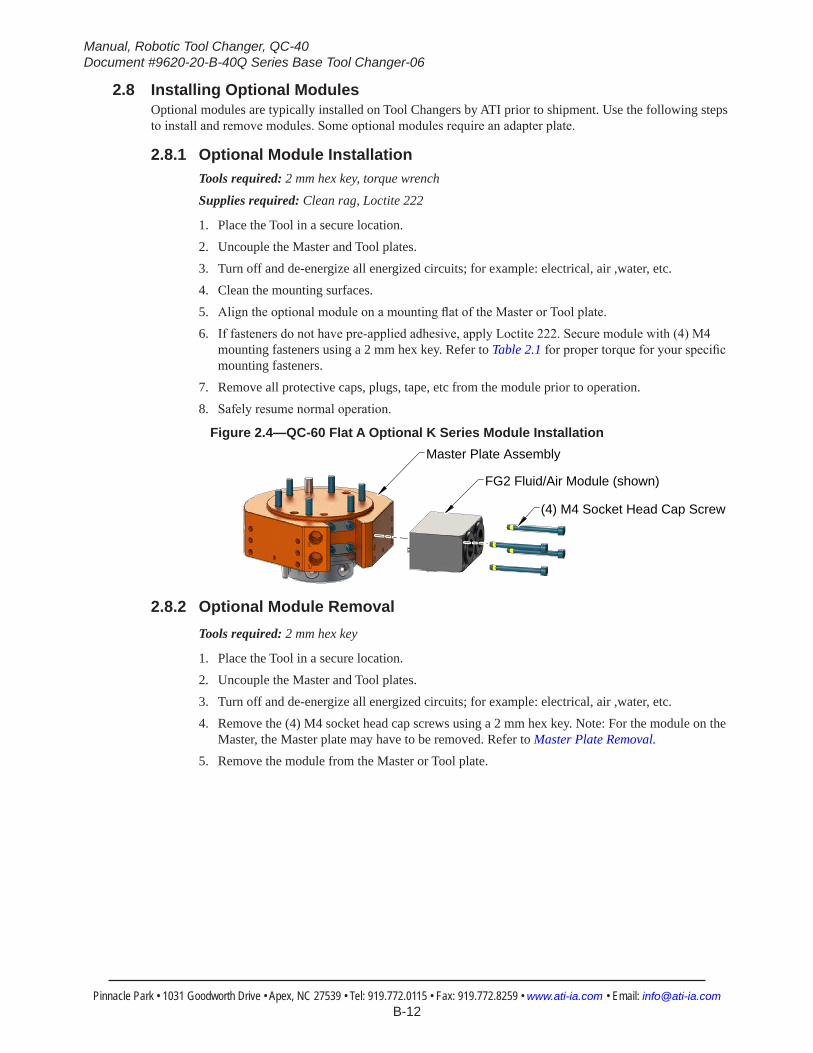
2.8 Installing Optional ModulesOptional modules are typically installed on Tool Changers by ATI prior to shipment. Use the following steps to install and remove modules. Some optional modules require an adapter plate.
2.8.1 Optional Module InstallationTools required: 2 mm hex key, torque wrench
Supplies required: Clean rag, Loctite 222
1. Place the Tool in a secure location.2. Uncouple the Master and Tool plates.3. Turn off and de‑energize all energized circuits; for example: electrical, air ,water, etc.4. Clean the mounting surfaces. 5. Align the optional module on a mounting flat of the Master or Tool plate.6. If fasteners do not have pre‑applied adhesive, apply Loctite 222. Secure module with (4) M4
mounting fasteners using a 2 mm hex key. Refer to Table 2.1 for proper torque for your specific mounting fasteners.
7. Remove all protective caps, plugs, tape, etc from the module prior to operation.8. Safely resume normal operation.
Figure 2.4—QC-60 Flat A Optional K Series Module Installation
(4) M4 Socket Head Cap Screw
FG2 Fluid/Air Module (shown)
Master Plate Assembly
2.8.2 Optional Module RemovalTools required: 2 mm hex key
1. Place the Tool in a secure location.2. Uncouple the Master and Tool plates.3. Turn off and de‑energize all energized circuits; for example: electrical, air ,water, etc.4. Remove the (4) M4 socket head cap screws using a 2 mm hex key. Note: For the module on the
Master, the Master plate may have to be removed. Refer to Master Plate Removal.5. Remove the module from the Master or Tool plate.
Manual, Robotic Tool Changer, QC‑40Document #9620‑20‑B‑40Q Series Base Tool Changer‑06
Pinnacle Park • 1031 Goodworth Drive • Apex, NC 27539 • Tel: 919.772.0115 • Fax: 919.772.8259 • www.ati‑ia.com • Email: info@ati‑ia.com B-13
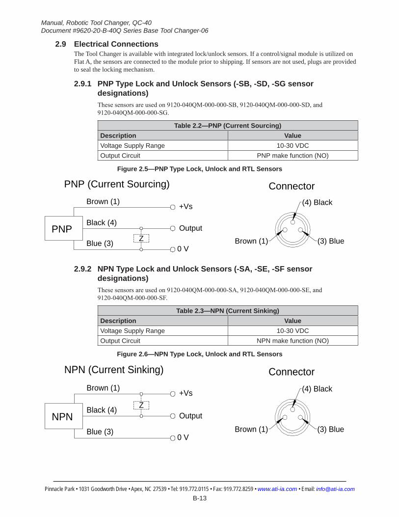
2.9 Electrical ConnectionsThe Tool Changer is available with integrated lock/unlock sensors. If a control/signal module is utilized on Flat A, the sensors are connected to the module prior to shipping. If sensors are not used, plugs are provided to seal the locking mechanism.
2.9.1 PNP Type Lock and Unlock Sensors (-SB, -SD, -SG sensor designations)These sensors are used on 9120‑040QM‑000‑000‑SB, 9120‑040QM‑000‑000‑SD, and 9120‑040QM‑000‑000‑SG.
Table 2.2—PNP (Current Sourcing)Description ValueVoltage Supply Range 10-30 VDCOutput Circuit PNP make function (NO)
Figure 2.5—PNP Type Lock, Unlock and RTL Sensors
(3) BlueBrown (1)
(4) BlackBrown (1)
Black (4)
Blue (3)
+Vs
Output
0 V
PNPZ
ConnectorPNP (Current Sourcing)
2.9.2 NPN Type Lock and Unlock Sensors (-SA, -SE, -SF sensor designations)These sensors are used on 9120‑040QM‑000‑000‑SA, 9120‑040QM‑000‑000‑SE, and 9120‑040QM‑000‑000‑SF.
Table 2.3—NPN (Current Sinking)Description ValueVoltage Supply Range 10-30 VDCOutput Circuit NPN make function (NO)
Figure 2.6—NPN Type Lock, Unlock and RTL Sensors
(3) BlueBrown (1)
(4) BlackBrown (1)
Black (4)
Blue (3)
+Vs
Output
0 V
NPNZ
ConnectorNPN (Current Sinking)
Manual, Robotic Tool Changer, QC‑40Document #9620‑20‑B‑40Q Series Base Tool Changer‑06
Pinnacle Park • 1031 Goodworth Drive • Apex, NC 27539 • Tel: 919.772.0115 • Fax: 919.772.8259 • www.ati‑ia.com • Email: info@ati‑ia.com B-14
3. OperationThe Master locking mechanism is pneumatically driven to couple and uncouple with the bearing race on the Tool plate. Lock and unlock air ports on the Master plate provide lock and unlock pressure to the locking mechanism.
CAUTION: Safe, reliable operation of the Tool Changer is dependent on a continuous supply of compressed air at a pressure of 60 to 100 psi. Robot motion should be halted if the air supply pressure drops below 60 psi for any reason.
NOTICE: All Tool Changers are initially lubricated using MobilGrease® XHP222 Special grease. The end user must apply additional lubricant to the locking mechanism components and alignment pins prior to start of service (see Section 4.2—Cleaning and Lubrication of the Locking Mechanism and Alignment Pins). Tubes of lubricant for this purpose are shipped with every Tool Changer. Note: MobilGrease XHP222 Special is a NLGI #2 lithium complex grease with molybdenum disulfide.
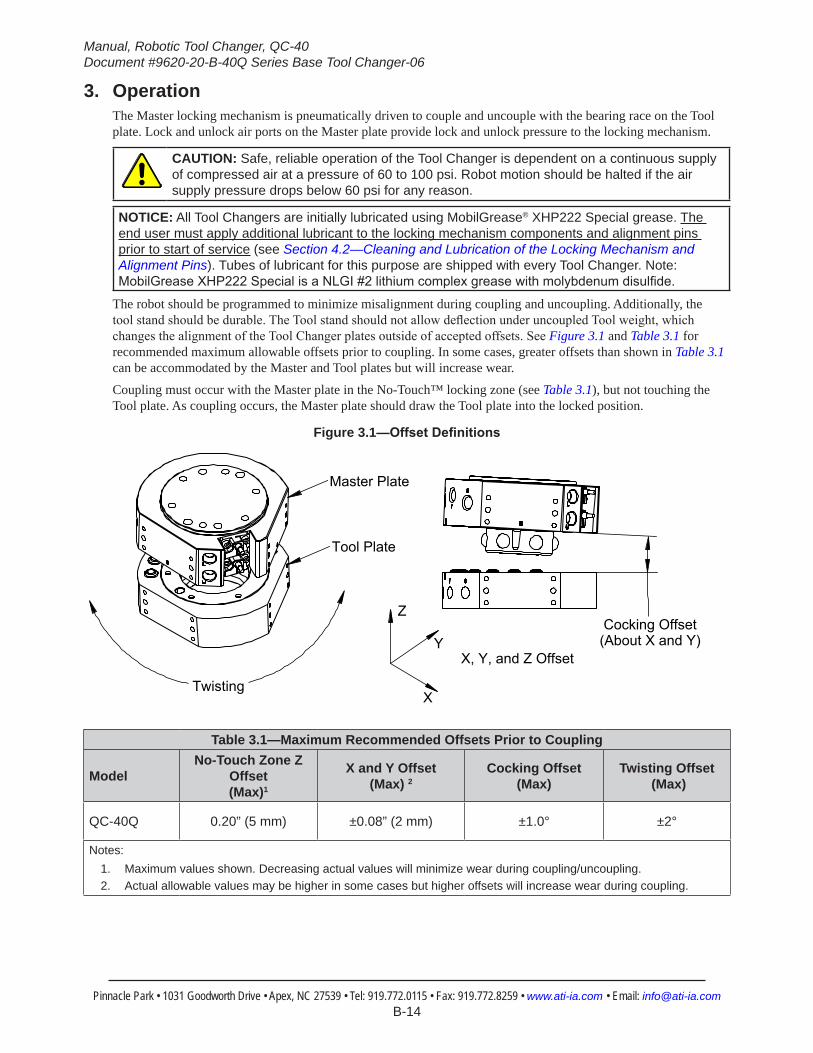
The robot should be programmed to minimize misalignment during coupling and uncoupling. Additionally, the tool stand should be durable. The Tool stand should not allow deflection under uncoupled Tool weight, which changes the alignment of the Tool Changer plates outside of accepted offsets. See Figure 3.1 and Table 3.1 for recommended maximum allowable offsets prior to coupling. In some cases, greater offsets than shown in Table 3.1 can be accommodated by the Master and Tool plates but will increase wear.
Coupling must occur with the Master plate in the No‑Touch™ locking zone (see Table 3.1), but not touching the Tool plate. As coupling occurs, the Master plate should draw the Tool plate into the locked position.
Figure 3.1—OffsetDefinitions
Twisting
Z
Y
Tool Plate
Master Plate
Cocking Offset(About X and Y)
X
X, Y, and Z Offset
Table 3.1—Maximum Recommended Offsets Prior to Coupling
ModelNo-Touch Zone Z
Offset (Max)1
X and Y Offset (Max) 2
Cocking Offset (Max)
Twisting Offset (Max)
QC-40Q 0.20” (5 mm) ±0.08” (2 mm) ±1.0° ±2°
Notes: 1. Maximum values shown. Decreasing actual values will minimize wear during coupling/uncoupling.2. Actual allowable values may be higher in some cases but higher offsets will increase wear during coupling.
Manual, Robotic Tool Changer, QC‑40Document #9620‑20‑B‑40Q Series Base Tool Changer‑06
Pinnacle Park • 1031 Goodworth Drive • Apex, NC 27539 • Tel: 919.772.0115 • Fax: 919.772.8259 • www.ati‑ia.com • Email: info@ati‑ia.com B-15
3.1 Conditions for CouplingCAUTION: The locking mechanism must be in the unlock position when attempting to couple the Tool Changer. Failure to adhere to this condition may result in damage to the unit and/or the robot.
1. Position the Master plate above the Tool plate with the air supplied to the Unlock Port (if equipped, the Unlock sensor indicates the Tool Changer is Unlocked).
2. Move the Master plate toward the Tool plate so that the (2) alignment pins enter the alignment holes on the opposite plate. Program the robot so that the Master plate and Tool plate are aligned axially and are parallel to each other (as closely as possible). This will minimize Tool movement and subsequent wear during lock‑up.
CAUTION: No-Touch™ locking technology allows the unit to couple with a separation distance between the Master and Tool. Direct contact of the Master and Tool mating surfaces is not suggested or required prior to coupling. Contact may result in damage to the unit and/or the robot.
3. When the (2) faces are within the specified No‑Touch™ distance, release the pressure from the Unlock port and supply air to the Lock port. The Tool plate is drawn toward the Master plate and coupled. Air must be maintained on the Lock Port during operation to assure rigid coupling (if equipped, the Lock sensor indicates the Tool Changer is in the Locked position).
4. A sufficient delay must be programmed between locking valve actuation and robot motion so that the locking process is complete before moving the robot.
CAUTION: If air pressure is lost during operation, ATI’s patented fail-safe design prevents the Tool plate from being released. Do not use the Tool Changer in a fail-safe condition. Re-establish air pressure and ensure the Tool Changer is in a secure lock position before returning to normal operations.
3.2 Fail-Safe OperationA fail‑safe condition occurs when there is an unintended loss of lock air pressure to the Master plate. When air pressure is lost, the Tool Changer relaxes and there may be a slight separation between the Master and Tool plates. The lock sensor may indicate that the unit is not locked. ATI’s patented fail‑safe feature utilizes a multi‑tapered cam to trap the ball bearings and prevent an unintended release of the Tool plate. Positional accuracy of the tooling is not maintained during this fail‑safe condition. Do not operate the Tool Changer in the fail‑safe condition. If source air is lost to the unit, movement should be halted until air pressure is restored. After air pressure is re‑established to the Master plate, the locking mechanism will energize and securely lock the Master and Tool plates together. In some cases when the load on the tool changer is significantly off center, it may be necessary to position the load underneath the tool changer or return the tool to the tool storage location to ensure a secure lock condition. If equipped, make sure the lock sensor indicates the Tool Changer is in the locked position before resuming normal operations. Consult your Control/Signal Module Manual for specific error recovery information.
CAUTION: Do not use the Tool Changer in a fail-safe condition. Damage to the locking mechanism could occur. Re-establish air pressure and ensure the Tool Changer is in a secure lock position before returning to normal operations.
Manual, Robotic Tool Changer, QC‑40Document #9620‑20‑B‑40Q Series Base Tool Changer‑06
Pinnacle Park • 1031 Goodworth Drive • Apex, NC 27539 • Tel: 919.772.0115 • Fax: 919.772.8259 • www.ati‑ia.com • Email: info@ati‑ia.com B-16
3.3 Conditions for Uncoupling1. Position the Tool plate in the tool stand so that there is little or no contact force between the Tool plate
and tool stand. 2. Release air on the Lock port and apply air to the Unlock Port (if equipped, the Unlock sensor will
indicate the Tool Changer is in the Unlocked position).
NOTICE: The air will cause the locking mechanism to be released and the weight of the Tool plate and attached tooling will assist in its removal. The Tool weight assists in uncoupling if the Tool is released in the vertical position only.
3. A sufficient delay must be programmed between unlocking valve actuation and robot motion, so that the unlocking process is complete and the Tool plate is fully released before moving the robot.
4. Move the Master plate axially away from the Tool plate.5. In automated Tool change applications, it is recommended that a Tool presence sensor(s) be used in the
tool stand to verify that the Tool is present and that the Tool remains in place as the robot moves away after the unlocking process.
3.4 Tool Storage ConsiderationsNOTICE: Tool stand design is critical to the operation of the Tool Changer. Improperly designed tool stands can cause jamming and excessive wear of the Tool Changer components.
Tool plates with customer tooling attached may be stored in a tool stand. ATI provides compatible tool stands designed for durability, longevity, and maximum adaptability to fit most customers’ applications. The ATI TSM (Tool Stand Medium) system is compatible with ATI Tool Changer sizes QC‑20 to QC‑110. The TSM systems can be equipped with horizontal modules, clamp modules, and different types of tool sensing. Visit the ATI Web Site http://www.ati‑ia.com/products/toolchanger/toolstand/medium/MediumStand.aspx for products available, or contact ATI for assistance.If the customer is supplying the tool stand, it must provide a fixed, repeatable, level, and stable position for tool pick‑up and drop‑off. The tool stand must support the weight of the Tool Changer Tool plate, tool interface plate, optional modules, cables, hoses, and customer tooling without allowing deflection in excess of the offsets specified.Ideally, the tool should be hanging vertically in the tool stand so that gravity assists to uncouple the Tool plate from the Master plate during unlocking. It is possible to design tool stands that hold tools in the horizontal position, but the necessary compliance must be provided during coupling and uncoupling. In general, “horizontal‑position” tool stands cause more wear on the locking mechanism and locating features of the Tool and tool stand. A variety of methods may be used to position the Tool in the tool stand. A common method is to use tapered alignment pins and bushings. Robot programming and positional repeatability are vital in tool pick‑up and drop‑off.A sensor that detects the presence of a Tool in the tool stand is recommended. The sensor may be used prior to coupling to ensure there is a Tool properly seated in the stand. Sensors may also be used as the robot starts to move away after uncoupling. Sensors provide safety measure if a Tool becomes jammed in the stand or if the Tool fails to release from the robot. Proximity sensors should be positioned so that the sensing face is vertical to prevent metal shavings, weld spatter, or other debris from falling on the sensor and creating false readings.Tool stands debris shields can cover Tools and modules to protect them in dirty environments, such as grinding or welding. Alternatively, positioning tool stands in areas shielded from weld spatter, fluids, adhesives, or other debris would eliminate the need for debris shields.

Manual, Robotic Tool Changer, QC‑40Document #9620‑20‑B‑40Q Series Base Tool Changer‑06
Pinnacle Park • 1031 Goodworth Drive • Apex, NC 27539 • Tel: 919.772.0115 • Fax: 919.772.8259 • www.ati‑ia.com • Email: info@ati‑ia.com B-17
4. MaintenanceWARNING: Do not perform maintenance or repair(s) on the Tool Changer or modules unless the Tool is safely supported or placed in the tool stand, all energized circuits (e.g. electrical, air, water, etc.) are turned off, pressurized connections are purged and power is discharged from circuits in accordance with the customer specific safety practices and policies. Injury or equipment damage can occur with the Tool not placed and energized circuits on. Place the Tool in the tool stand, turn off and discharge all energized circuits, purge all pressurized connections, and verify all circuits are de-energized before performing maintenance or repair(s) on the Tool Changer or modules.
NOTICE: The cleanliness of the work environment strongly influences the trouble free operation of the Tool Changer. The dirtier the environment, the greater the need for protection against debris. Protection of the entire EOAT, the Master, the Tool and all of the modules may be necessary. Protective measures include the following:Placement of the tool stands away from the debris generators.• Covers incorporated into the tool stands.• Guards, deflectors, air curtains, and similar devices built into the EOAT and the tool stand.
4.1 Preventive MaintenanceThe Tool Changer and optional modules are designed to provide a long life with regular maintenance. A visual inspection and preventive maintenance schedule is provided in the table below depending upon the application. Detailed assembly drawings are provided in Section 8—Drawings of this manual. Refer to module sections for detailed preventive maintenance steps for all utility modules.
Table 4.1—MaintenanceApplication(s) Tool Change Frequency Inspection Schedule
General Usage Material Handling Docking Station> 1 per minute Weekly
< 1 per minute Monthly
Welding/Servo/Deburring, Foundry Operations (Dirty Environments) All Weekly
ChecklistMounting Fasteners
г Inspect fasteners for proper torque, interferences, and wear. Tighten and correct as required. Refer to “Table 2.1—Fastener Size, Class, and Torque Specifications”.
Ball Bearings/Alignment Pins/Bushings/Bearing Race г Inspect for wear and proper lubrication. MobilGrease XHP222 Special a NLGI #2 lithium complex grease with
molybdenum disulfide additive is suggested for locking mechanism and alignment pin lubrication. Over time, lubricants can become contaminated with debris. Therefore, it is recommended to thoroughly clean the existing grease and replace with new as needed. See Section 4.2—Cleaning and Lubrication of the Locking Mechanism and Alignment Pins.
г Inspect for excessive alignment pin/bushing wear, may be an indication of poor robot position during pickup/drop-off. Adjust robot position as needed. Check tool stand for wear and alignment problems.
г Inspect for wear on the ball bearings/bearing race, may be an indication of excessive loading.Sensors and Cables
г Inspect sensor cable connectors for tightness, if loose tighten connections.
г Inspect sensor cables for any damage, cuts, and abrasion. Replace as necessary. Refer to Section 5.2.2—Lock and Unlock Sensor Assembly Replacement.
Hoses г Inspect hose connection for tightness and leaks. If leaking or loose secure hose connection.
г Inspect hoses for interferences, abrasions, cuts, and leaks. Replace as required.Electrical Contacts/Pin Block (Modules)
г Inspect for damage, debris, and stuck/burnt pins. Clean pin blocks as required, Refer to Section 4.3—Pin Block Inspection and Cleaning.
Seals (Modules) г Inspect for wear, abrasion, and cuts. Refer to Section 5.2.1—V‑ring Seal Replacement.
Manual, Robotic Tool Changer, QC‑40Document #9620‑20‑B‑40Q Series Base Tool Changer‑06
Pinnacle Park • 1031 Goodworth Drive • Apex, NC 27539 • Tel: 919.772.0115 • Fax: 919.772.8259 • www.ati‑ia.com • Email: info@ati‑ia.com B-18
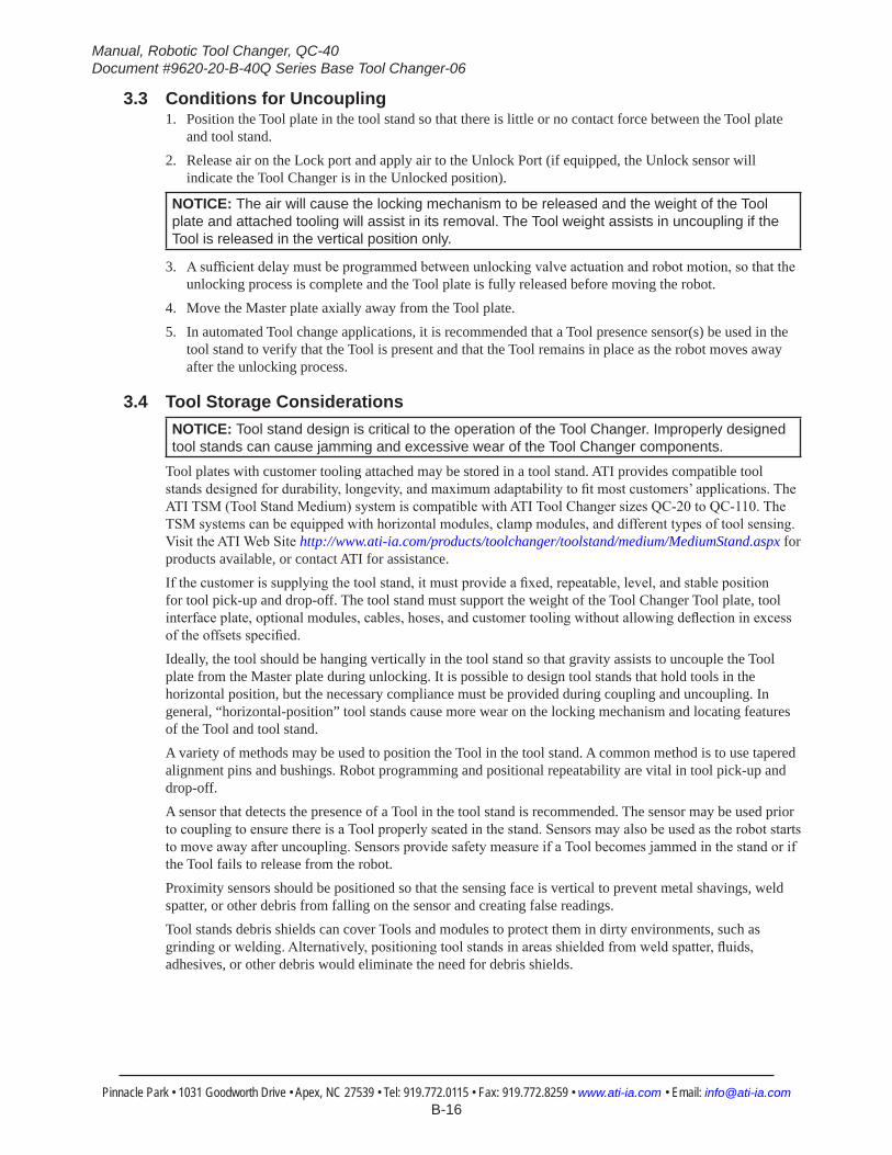
4.2 Cleaning and Lubrication of the Locking Mechanism and Alignment PinsSupplies required: Clean rag, MobilGrease XHP222 Special is a NLGI #2 lithium complex grease with
molybdenum disulfide1. Place the Tool in a secure location.2. Uncouple the Master and Tool plates.3. Turn off and de‑energize all energized circuits (e.g. electrical, air, water, etc.).4. Use a clean rag to thoroughly remove any lubricant and debris from the ball bearings, male coupling,
cam, and alignment pins.
Figure 4.1—Cleaning Ball Bearings and Outer Surfaces of Male Coupling
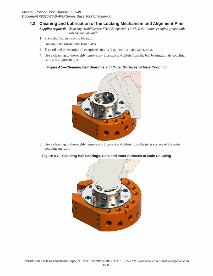
5. Use a clean rag to thoroughly remove any lubricant and debris from the inner surface of the male coupling and cam.
Figure 4.2—Cleaning Ball Bearings, Cam and Inner Surfaces of Male Coupling

Manual, Robotic Tool Changer, QC‑40Document #9620‑20‑B‑40Q Series Base Tool Changer‑06
Pinnacle Park • 1031 Goodworth Drive • Apex, NC 27539 • Tel: 919.772.0115 • Fax: 919.772.8259 • www.ati‑ia.com • Email: info@ati‑ia.com B-19
6. Check each ball bearing to make sure it moves freely in the male coupling. Additional cleaning may be necessary to free up any ball bearings that are sticking in place.
Figure 4.3—Check Ball Bearing Movement
7. Apply a liberal coating of lubricant to the ball bearings, the male coupling (inside and out), and the alignment pins.
Figure 4.4—Apply Lubricant to Locking Mechanism
Apply Lubricant on Alignment PinsApply Lubricant on Alignment Pins
Apply Lubricant on Innerand Outer Surfaces of Male CouplingApply Lubricant on Innerand Outer Surfaces of Male Coupling
8. Use a clean rag to thoroughly remove any lubricant and debris from the Tool plate bearing race and bushings.
NOTICE: No application of lubrication is necessary on the Tool plate components.
9. Safely resume normal operation.
Figure 4.5—Clean Tool Plate Surfaces of Locking Mechanism
Clean Bushing SurfacesClean Bushing Surfaces
Clean Bearing Race SurfacesClean Bearing Race Surfaces
Manual, Robotic Tool Changer, QC‑40Document #9620‑20‑B‑40Q Series Base Tool Changer‑06
Pinnacle Park • 1031 Goodworth Drive • Apex, NC 27539 • Tel: 919.772.0115 • Fax: 919.772.8259 • www.ati‑ia.com • Email: info@ati‑ia.com B-20
4.3 Pin Block Inspection and CleaningTools required: Nylon Brush (ATI Part Number 3690‑0000064‑60)
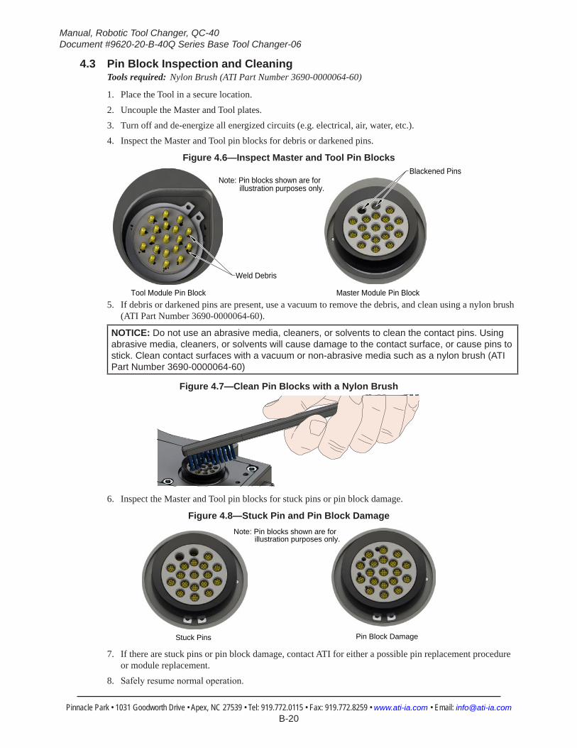
1. Place the Tool in a secure location.2. Uncouple the Master and Tool plates.3. Turn off and de‑energize all energized circuits (e.g. electrical, air, water, etc.).4. Inspect the Master and Tool pin blocks for debris or darkened pins.
Figure 4.6—Inspect Master and Tool Pin Blocks
Tool Module Pin Block Master Module Pin Block
Note: Pin blocks shown are for illustration purposes only.
Weld Debris
Blackened Pins
5. If debris or darkened pins are present, use a vacuum to remove the debris, and clean using a nylon brush (ATI Part Number 3690‑0000064‑60).
NOTICE: Do not use an abrasive media, cleaners, or solvents to clean the contact pins. Using abrasive media, cleaners, or solvents will cause damage to the contact surface, or cause pins to stick. Clean contact surfaces with a vacuum or non-abrasive media such as a nylon brush (ATI Part Number 3690-0000064-60)
Figure 4.7—Clean Pin Blocks with a Nylon Brush
6. Inspect the Master and Tool pin blocks for stuck pins or pin block damage.
Figure 4.8—Stuck Pin and Pin Block Damage
Stuck Pins Pin Block Damage
Note: Pin blocks shown are for illustration purposes only.
7. If there are stuck pins or pin block damage, contact ATI for either a possible pin replacement procedure or module replacement.
8. Safely resume normal operation.

Manual, Robotic Tool Changer, QC‑40Document #9620‑20‑B‑40Q Series Base Tool Changer‑06
Pinnacle Park • 1031 Goodworth Drive • Apex, NC 27539 • Tel: 919.772.0115 • Fax: 919.772.8259 • www.ati‑ia.com • Email: info@ati‑ia.com B-21
5. Troubleshooting and Service ProceduresThe following section provides troubleshooting and service information to help diagnose conditions and repair the Tool Changer or control/signal module.
WARNING: Do not perform maintenance or repair(s) on the Tool Changer or modules unless the Tool is safely supported or placed in the tool stand, all energized circuits (e.g. electrical, air, water, etc.) are turned off, pressurized connections are purged and power is discharged from circuits in accordance with the customer specific safety practices and policies. Injury or equipment damage can occur with the Tool not placed and energized circuits on. Place the Tool in the tool stand, turn off and discharge all energized circuits, purge all pressurized connections, and verify all circuits are de-energized before performing maintenance or repair(s) on the Tool Changer or modules.
5.1 Troubleshooting ProceduresThe troubleshooting table is provided to assist in diagnosing issues that may cause the Tool Changer to malfunction.
Table 5.1—TroubleshootingSymptom Cause Resolution
Tool Changer unable to lock and/or unlock (or Lock sensor does not indicate Tool Changer is locked).
Debris caught between the Master and Tool plates.
Clean debris from between Master and Tool plates. Verify mounting fasteners is secure and does not protrude above the mating surfaces.
Insufficient or no air pressure supply to the lock or unlock ports.
Verify proper air pressure and pneumatic valve is supplied. Refer to Section 2.7—Pneumatic Connections.
Air pressure trapped in de-energized Lock or Unlock ports.
Air pressure must be vented to the atmosphere properly, refer to Section 2.7—Pneumatic Connections.
Pneumatic connections loose or damaged.
Inspect hose connection for tightness and leaks. If leaking or loose secure hose connection.
Inspect hoses for interferences, abrasions, cuts, and leaks. Replace as required.
The ball bearings and/or cam are not moving freely in the male coupling.
Clean and lubricate as needed to restore smooth operation. See Section 4.2—Cleaning and Lubrication of the Locking Mechanism and Alignment Pins.
The Master plate and Tool plate are not within the specified No-Touch zone when attempting to lock.
Check that the Tool is properly seated in the tool stand. Refer to Section 3.4—Tool Storage Considerations.
Re-teach the robot to bring the Master plate and Tool plate closer together prior to attempting to lock.
Unit is locked but Lock signal does not read “on” (true).
Lock sensor/cable is out of adjustment or damaged.
Adjust or replace the lock sensor assembly as necessary. Refer to Section 5.2.2—Lock and Unlock Sensor Assembly Replacement.
Unit is unlocked but Unlock signal does not read “on” (true).
Unlock sensor/cable is out of adjustment or damaged.
Adjust or replace the unlock sensor assembly as necessary. Refer to Section 5.2.2—Lock and Unlock Sensor Assembly Replacement.
Units Equipped with Electrical/Servo/Control/Signal Modules
Loss of communication.
Debris in and around contact pins. Contact Pin worn or damaged.
Inspect V-ring seal for damage, replace damaged seal. Refer to Section 5.2.1—V‑ring Seal Replacement.
Cable connections loose or cables damaged.
Check that cable connection are secure and cables are not damaged.
Manual, Robotic Tool Changer, QC‑40Document #9620‑20‑B‑40Q Series Base Tool Changer‑06
Pinnacle Park • 1031 Goodworth Drive • Apex, NC 27539 • Tel: 919.772.0115 • Fax: 919.772.8259 • www.ati‑ia.com • Email: info@ati‑ia.com B-22
5.2 Service ProceduresComponent replacement procedures are provided in the following section.
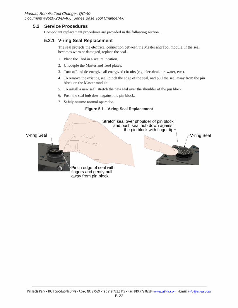
5.2.1 V-ring Seal ReplacementThe seal protects the electrical connection between the Master and Tool module. If the seal becomes worn or damaged, replace the seal.
1. Place the Tool in a secure location.2. Uncouple the Master and Tool plates.3. Turn off and de‑energize all energized circuits (e.g. electrical, air, water, etc.).4. To remove the existing seal, pinch the edge of the seal, and pull the seal away from the pin
block on the Master module.5. To install a new seal, stretch the new seal over the shoulder of the pin block.6. Push the seal hub down against the pin block.
7. Safely resume normal operation.
Figure 5.1—V-ring Seal Replacement
V-ring Seal
Stretch seal over shoulder of pin block and push seal hub down against
the pin block with finger tipV-ring Seal
Pinch edge of seal with fingers and gently pull away from pin block

Manual, Robotic Tool Changer, QC‑40Document #9620‑20‑B‑40Q Series Base Tool Changer‑06
Pinnacle Park • 1031 Goodworth Drive • Apex, NC 27539 • Tel: 919.772.0115 • Fax: 919.772.8259 • www.ati‑ia.com • Email: info@ati‑ia.com B-23
5.2.2 Lock and Unlock Sensor Assembly ReplacementParts required: Refer to Section 6—Serviceable PartsTools required: 1.5 mm hex key, torque wrench
1. Place the Tool in a secure location.2. Uncouple the Master and Tool plates.3. Turn off and de‑energize all energized circuits; for example, electrical, air, water, etc.4. Disconnect the Lock and/or Unlock sensor cables.5. Remove the (2) M3 socket head cap screws that secure the Lock and/or Unlock sensor assembly
to the Tool Changer body. Pull the sensor assembly straight out from the Tool Changer body. Ensure the O‑ring around the cylinder barrel is removed with the old sensor before continuing. Discard the removed sensor assembly.
CAUTION: The Lock and Unlock sensor assemblies are precision aligned and permanently assembled at the factory. Do not attempt to disassemble and rebuild.
Figure 5.2—Lock and Unlock Sensor Assembly Replacement
Lock Sensor Assembly
Unlock Sensor Assembly
M3 Socket Head Cap Screws
6. Install the Lock and/or Unlock sensor assembly into the Tool Changer body as shown in Figure 5.2.
7. Secure the sensor assembly using the (2) M3 socket flat head screws. Tighten to 12 in‑lbs (1.4 Nm).
8. Connect the Lock and/or Unlock sensor cables.9. Confirm the operation of the Lock sensor by locking the Tool Changer and then checking to see
if the Lock sensor body LED is on.10. Confirm the operation of the Unlock sensor by unlocking the Tool Changer and then checking
to see if the Unlock sensor body LED is on.11. Safely resume normal operation.
Manual, Robotic Tool Changer, QC‑40Document #9620‑20‑B‑40Q Series Base Tool Changer‑06
Pinnacle Park • 1031 Goodworth Drive • Apex, NC 27539 • Tel: 919.772.0115 • Fax: 919.772.8259 • www.ati‑ia.com • Email: info@ati‑ia.com B-24
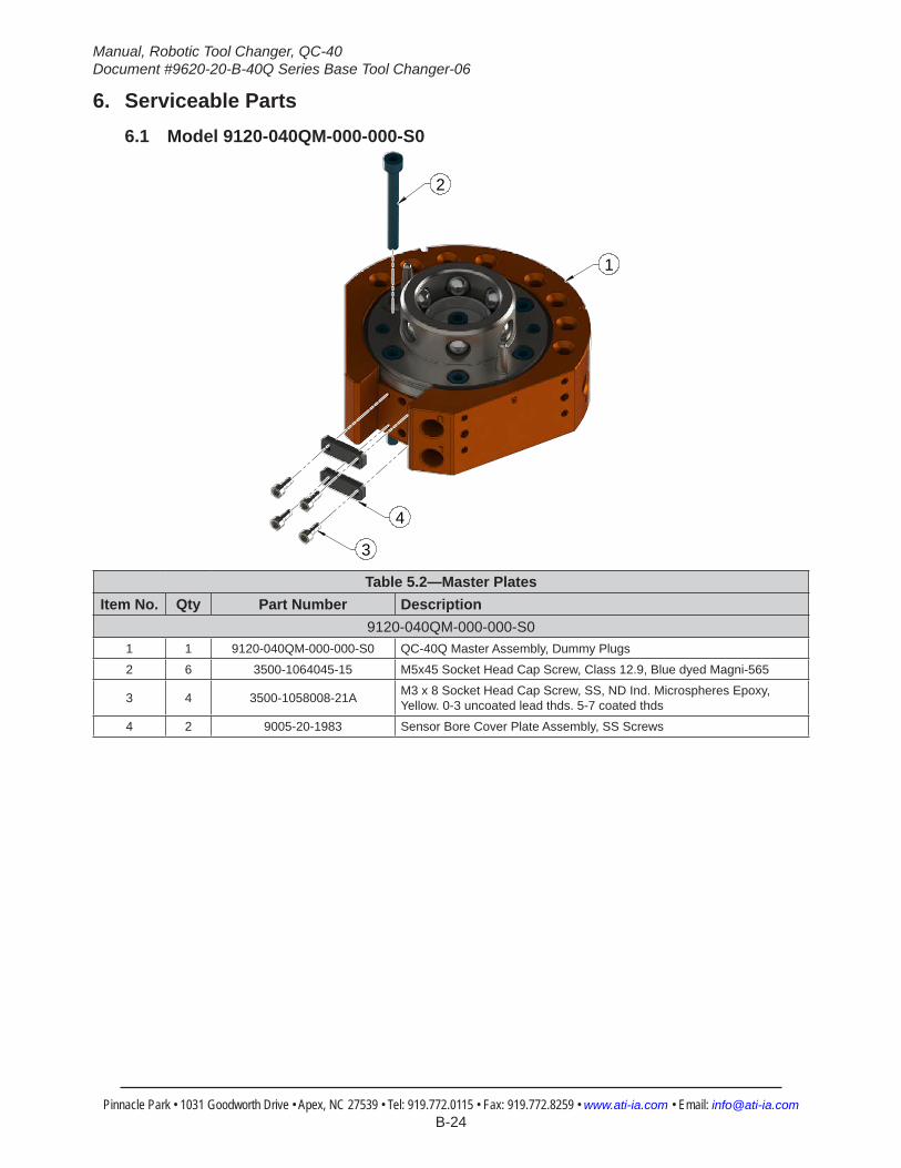
6. Serviceable Parts6.1 Model 9120-040QM-000-000-S0
2
1
4
3
Table 5.2—Master PlatesItem No. Qty Part Number Description
9120-040QM-000-000-S01 1 9120-040QM-000-000-S0 QC-40Q Master Assembly, Dummy Plugs
2 6 3500-1064045-15 M5x45 Socket Head Cap Screw, Class 12.9, Blue dyed Magni-565
3 4 3500-1058008-21A M3 x 8 Socket Head Cap Screw, SS, ND Ind. Microspheres Epoxy, Yellow. 0-3 uncoated lead thds. 5-7 coated thds
4 2 9005-20-1983 Sensor Bore Cover Plate Assembly, SS Screws

Manual, Robotic Tool Changer, QC‑40Document #9620‑20‑B‑40Q Series Base Tool Changer‑06
Pinnacle Park • 1031 Goodworth Drive • Apex, NC 27539 • Tel: 919.772.0115 • Fax: 919.772.8259 • www.ati‑ia.com • Email: info@ati‑ia.com B-25
6.2 Model 9120-040QM-000-000-S0-E
4
5
1
2 3
Table 5.3—Master PlatesItem No. Qty Part Number Description
9120-040QM-000-000-S0-E1 1 9120-040QM-000-000-S0-E QC-40Q Master Assembly, Dummy Plugs, Euro
2 6 3500-1064045-15 M5x45 Socket Head Cap Screw, Class 12.9, Blue dyed Magni-565
3 8 4010-0000013-01 1/8 Nitrile Rubber Bushing
4 4 3500-1058008-21A M3 x 8 Socket Head Cap Screw, SS, ND Ind. Microspheres Epoxy, Yellow. 0-3 uncoated lead thds. 5-7 coated thds
5 2 9005-20-1983 Sensor Bore Cover Plate Assembly, SS Screws
Manual, Robotic Tool Changer, QC‑40Document #9620‑20‑B‑40Q Series Base Tool Changer‑06
Pinnacle Park • 1031 Goodworth Drive • Apex, NC 27539 • Tel: 919.772.0115 • Fax: 919.772.8259 • www.ati‑ia.com • Email: info@ati‑ia.com B-26
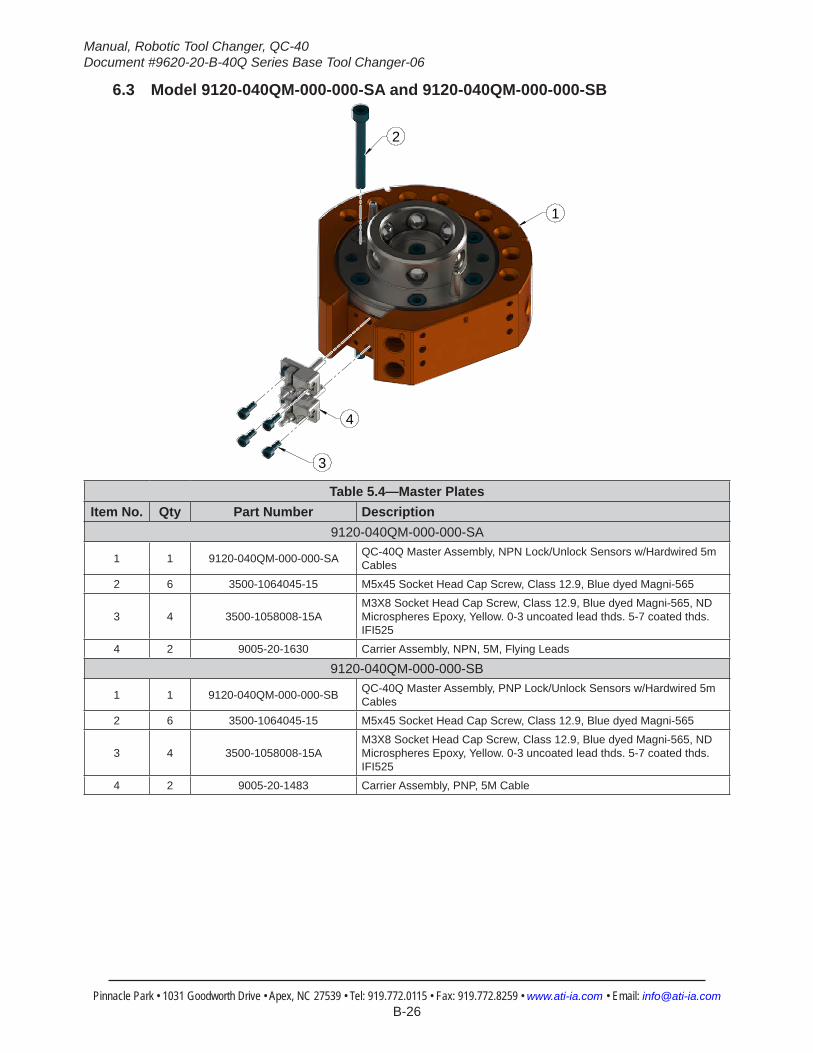
6.3 Model 9120-040QM-000-000-SA and 9120-040QM-000-000-SB
2
1
4
3
Table 5.4—Master Plates Item No. Qty Part Number Description
9120-040QM-000-000-SA
1 1 9120-040QM-000-000-SA QC-40Q Master Assembly, NPN Lock/Unlock Sensors w/Hardwired 5m Cables
2 6 3500-1064045-15 M5x45 Socket Head Cap Screw, Class 12.9, Blue dyed Magni-565
3 4 3500-1058008-15AM3X8 Socket Head Cap Screw, Class 12.9, Blue dyed Magni-565, ND Microspheres Epoxy, Yellow. 0-3 uncoated lead thds. 5-7 coated thds. IFI525
4 2 9005-20-1630 Carrier Assembly, NPN, 5M, Flying Leads
9120-040QM-000-000-SB
1 1 9120-040QM-000-000-SB QC-40Q Master Assembly, PNP Lock/Unlock Sensors w/Hardwired 5m Cables
2 6 3500-1064045-15 M5x45 Socket Head Cap Screw, Class 12.9, Blue dyed Magni-565
3 4 3500-1058008-15AM3X8 Socket Head Cap Screw, Class 12.9, Blue dyed Magni-565, ND Microspheres Epoxy, Yellow. 0-3 uncoated lead thds. 5-7 coated thds. IFI525
4 2 9005-20-1483 Carrier Assembly, PNP, 5M Cable

Manual, Robotic Tool Changer, QC‑40Document #9620‑20‑B‑40Q Series Base Tool Changer‑06
Pinnacle Park • 1031 Goodworth Drive • Apex, NC 27539 • Tel: 919.772.0115 • Fax: 919.772.8259 • www.ati‑ia.com • Email: info@ati‑ia.com B-27
6.4 Model 9120-040QM-000-000-SA-E and 9120-040QM-000-000-SB-E
2
3
1
5
4
Table 5.5—Master Plates Item No. Qty Part Number Description
9120-040QM-000-000-SA-E
1 1 9120-040QM-000-000-SA-E QC-40Q Master Assembly, NPN Lock/Unlock Sensors w/Hardwired 5m Cables, Euro
2 6 3500-1064045-15 M5x45 Socket Head Cap Screw, Class 12.9, Blue dyed Magni-565
3 8 4010-0000013-01 1/8 Nitrile Rubber Bushing
4 4 3500-1058008-15AM3X8 Socket Head Cap Screw, Class 12.9, Blue dyed Magni-565, ND Microspheres Epoxy, Yellow. 0-3 uncoated lead thds. 5-7 coated thds. IFI525
5 2 9005-20-1630 Carrier Assembly, NPN, 5M, Flying Leads
9120-040QM-000-000-SB-E
1 1 9120-040QM-000-000-SB-E QC-40Q Master Assembly, PNP Lock/Unlock Sensors w/Hardwired 5m Cables, Euro
2 6 3500-1064045-15 M5x45 Socket Head Cap Screw, Class 12.9, Blue dyed Magni-565
3 8 4010-0000013-01 1/8 Nitrile Rubber Bushing
4 4 3500-1058008-15AM3X8 Socket Head Cap Screw, Class 12.9, Blue dyed Magni-565, ND Microspheres Epoxy, Yellow. 0-3 uncoated lead thds. 5-7 coated thds. IFI525
5 2 9005-20-1483 Carrier Assembly, PNP, 5M Cable

Manual, Robotic Tool Changer, QC‑40Document #9620‑20‑B‑40Q Series Base Tool Changer‑06
Pinnacle Park • 1031 Goodworth Drive • Apex, NC 27539 • Tel: 919.772.0115 • Fax: 919.772.8259 • www.ati‑ia.com • Email: info@ati‑ia.com B-28
6.5 Model 9120-040QM-000-000-SD and 9120-040QM-000-000-SF
2
1
3
4
5
Table 5.6—Master Plates Item No. Qty Part Number Description
9120-040QM-000-000-SD
1 1 9120-040QM-000-000-SD QC-40Q Master Assembly, PNP Quick Disconnect Lock/Unlock Sensors, 5m Cables
2 6 3500-1064045-15 M5x45 Socket Head Cap Screw, Class 12.9, Blue dyed Magni-565
3 4 3500-1058008-15AM3X8 Socket Head Cap Screw, Class 12.9, Blue dyed Magni-565, ND Microspheres Epoxy, Yellow. 0-3 uncoated lead thds. 5-7 coated thds. IFI525
4 2 9005-20-1628 Carrier Assembly, PNP Quick Disconnect
5 2 8590-9909999-07 High‑flex cable with straight snap‑on connector, 5M long with flying leads (Type ‑ BU)
9120-040QM-000-000-SF
1 1 9120-040QM-000-000-SF QC-40Q Master Assembly, NPN Quick Disconnect Lock/Unlock Sensors, 5m Cables
2 6 3500-1064045-15 M5x45 Socket Head Cap Screw, Class 12.9, Blue dyed Magni-565
3 4 3500-1058008-15AM3X8 Socket Head Cap Screw, Class 12.9, Blue dyed Magni-565, ND Microspheres Epoxy, Yellow. 0-3 uncoated lead thds. 5-7 coated thds. IFI525
4 2 9005-20-1629 Carrier Assembly, NPN Quick Disconnect
5 2 8590-9909999-07 High‑flex cable with straight snap‑on connector, 5M long with flying leads (Type ‑ BU)
Manual, Robotic Tool Changer, QC‑40Document #9620‑20‑B‑40Q Series Base Tool Changer‑06
Pinnacle Park • 1031 Goodworth Drive • Apex, NC 27539 • Tel: 919.772.0115 • Fax: 919.772.8259 • www.ati‑ia.com • Email: info@ati‑ia.com B-29
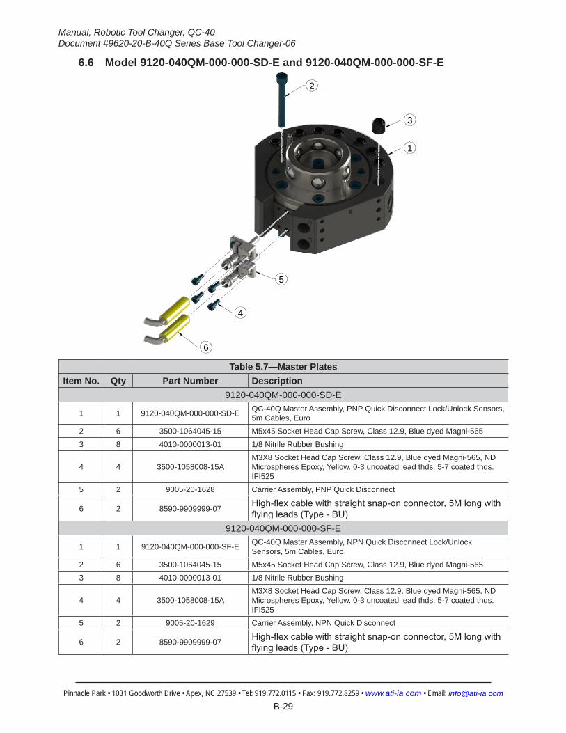
6.6 Model 9120-040QM-000-000-SD-E and 9120-040QM-000-000-SF-E
2
3
1
4
5
6
Table 5.7—Master Plates Item No. Qty Part Number Description
9120-040QM-000-000-SD-E
1 1 9120-040QM-000-000-SD-E QC-40Q Master Assembly, PNP Quick Disconnect Lock/Unlock Sensors, 5m Cables, Euro
2 6 3500-1064045-15 M5x45 Socket Head Cap Screw, Class 12.9, Blue dyed Magni-565
3 8 4010-0000013-01 1/8 Nitrile Rubber Bushing
4 4 3500-1058008-15AM3X8 Socket Head Cap Screw, Class 12.9, Blue dyed Magni-565, ND Microspheres Epoxy, Yellow. 0-3 uncoated lead thds. 5-7 coated thds. IFI525
5 2 9005-20-1628 Carrier Assembly, PNP Quick Disconnect
6 2 8590-9909999-07 High‑flex cable with straight snap‑on connector, 5M long with flying leads (Type ‑ BU)
9120-040QM-000-000-SF-E
1 1 9120-040QM-000-000-SF-E QC-40Q Master Assembly, NPN Quick Disconnect Lock/Unlock Sensors, 5m Cables, Euro
2 6 3500-1064045-15 M5x45 Socket Head Cap Screw, Class 12.9, Blue dyed Magni-565
3 8 4010-0000013-01 1/8 Nitrile Rubber Bushing
4 4 3500-1058008-15AM3X8 Socket Head Cap Screw, Class 12.9, Blue dyed Magni-565, ND Microspheres Epoxy, Yellow. 0-3 uncoated lead thds. 5-7 coated thds. IFI525
5 2 9005-20-1629 Carrier Assembly, NPN Quick Disconnect
6 2 8590-9909999-07 High‑flex cable with straight snap‑on connector, 5M long with flying leads (Type ‑ BU)
Manual, Robotic Tool Changer, QC‑40Document #9620‑20‑B‑40Q Series Base Tool Changer‑06
Pinnacle Park • 1031 Goodworth Drive • Apex, NC 27539 • Tel: 919.772.0115 • Fax: 919.772.8259 • www.ati‑ia.com • Email: info@ati‑ia.com B-30
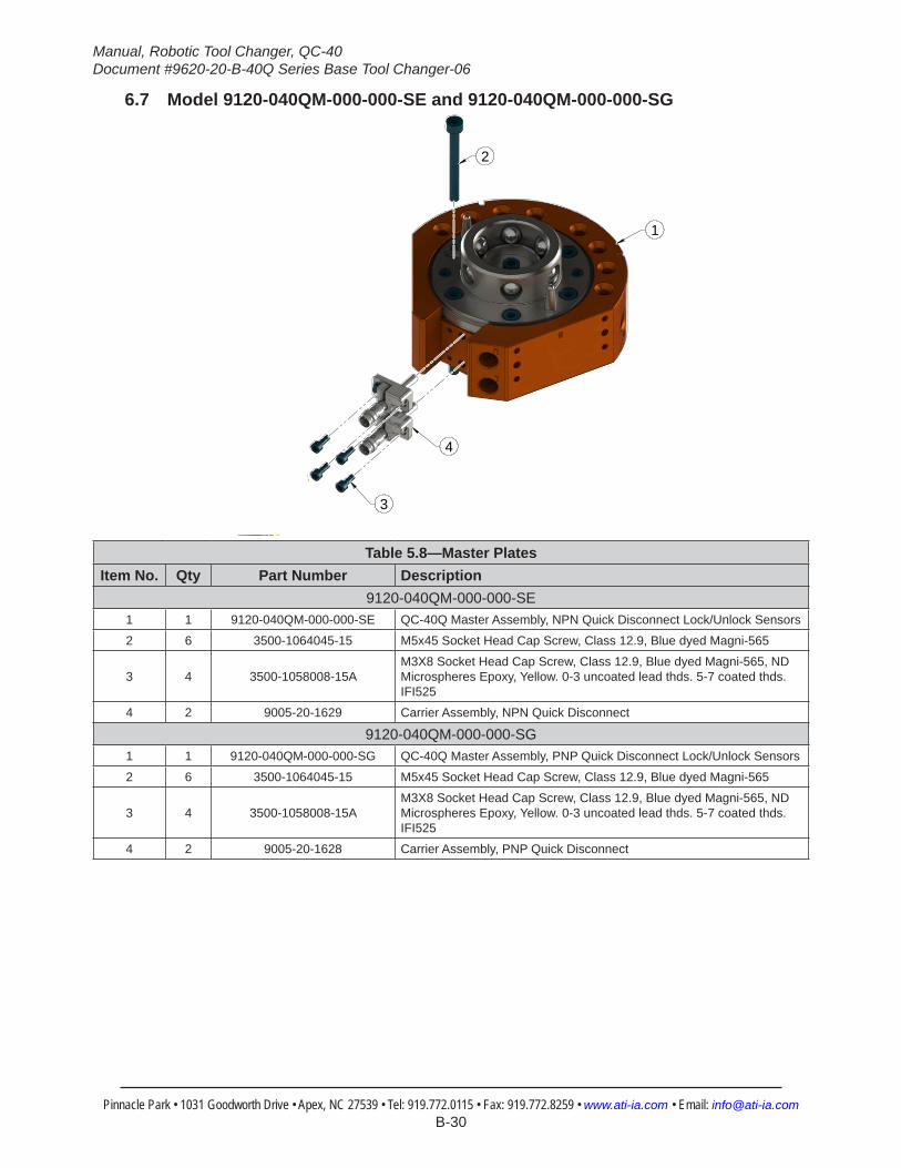
6.7 Model 9120-040QM-000-000-SE and 9120-040QM-000-000-SG
2
1
3
4
5 Table 5.8—Master Plates Item No. Qty Part Number Description
9120-040QM-000-000-SE1 1 9120-040QM-000-000-SE QC-40Q Master Assembly, NPN Quick Disconnect Lock/Unlock Sensors
2 6 3500-1064045-15 M5x45 Socket Head Cap Screw, Class 12.9, Blue dyed Magni-565
3 4 3500-1058008-15AM3X8 Socket Head Cap Screw, Class 12.9, Blue dyed Magni-565, ND Microspheres Epoxy, Yellow. 0-3 uncoated lead thds. 5-7 coated thds. IFI525
4 2 9005-20-1629 Carrier Assembly, NPN Quick Disconnect
9120-040QM-000-000-SG1 1 9120-040QM-000-000-SG QC-40Q Master Assembly, PNP Quick Disconnect Lock/Unlock Sensors
2 6 3500-1064045-15 M5x45 Socket Head Cap Screw, Class 12.9, Blue dyed Magni-565
3 4 3500-1058008-15AM3X8 Socket Head Cap Screw, Class 12.9, Blue dyed Magni-565, ND Microspheres Epoxy, Yellow. 0-3 uncoated lead thds. 5-7 coated thds. IFI525
4 2 9005-20-1628 Carrier Assembly, PNP Quick Disconnect
Manual, Robotic Tool Changer, QC‑40Document #9620‑20‑B‑40Q Series Base Tool Changer‑06
Pinnacle Park • 1031 Goodworth Drive • Apex, NC 27539 • Tel: 919.772.0115 • Fax: 919.772.8259 • www.ati‑ia.com • Email: info@ati‑ia.com B-31
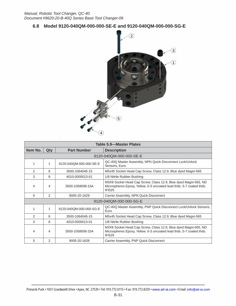
6.8 Model 9120-040QM-000-000-SE-E and 9120-040QM-000-000-SG-E
2
3
1
4
5
6Table 5.9—Master Plates
Item No. Qty Part Number Description9120-040QM-000-000-SE-E
1 1 9120-040QM-000-000-SE-E QC-40Q Master Assembly, NPN Quick Disconnect Lock/Unlock Sensors, Euro
2 6 3500-1064045-15 M5x45 Socket Head Cap Screw, Class 12.9, Blue dyed Magni-565
3 8 4010-0000013-01 1/8 Nitrile Rubber Bushing
4 4 3500-1058008-15AM3X8 Socket Head Cap Screw, Class 12.9, Blue dyed Magni-565, ND Microspheres Epoxy, Yellow. 0-3 uncoated lead thds. 5-7 coated thds. IFI525
5 2 9005-20-1629 Carrier Assembly, NPN Quick Disconnect
9120-040QM-000-000-SG-E
1 1 9120-040QM-000-000-SG-E QC-40Q Master Assembly, PNP Quick Disconnect Lock/Unlock Sensors, Euro
2 6 3500-1064045-15 M5x45 Socket Head Cap Screw, Class 12.9, Blue dyed Magni-565
3 8 4010-0000013-01 1/8 Nitrile Rubber Bushing
4 4 3500-1058008-15AM3X8 Socket Head Cap Screw, Class 12.9, Blue dyed Magni-565, ND Microspheres Epoxy, Yellow. 0-3 uncoated lead thds. 5-7 coated thds. IFI525
5 2 9005-20-1628 Carrier Assembly, PNP Quick Disconnect
Manual, Robotic Tool Changer, QC‑40Document #9620‑20‑B‑40Q Series Base Tool Changer‑06
Pinnacle Park • 1031 Goodworth Drive • Apex, NC 27539 • Tel: 919.772.0115 • Fax: 919.772.8259 • www.ati‑ia.com • Email: info@ati‑ia.com B-32
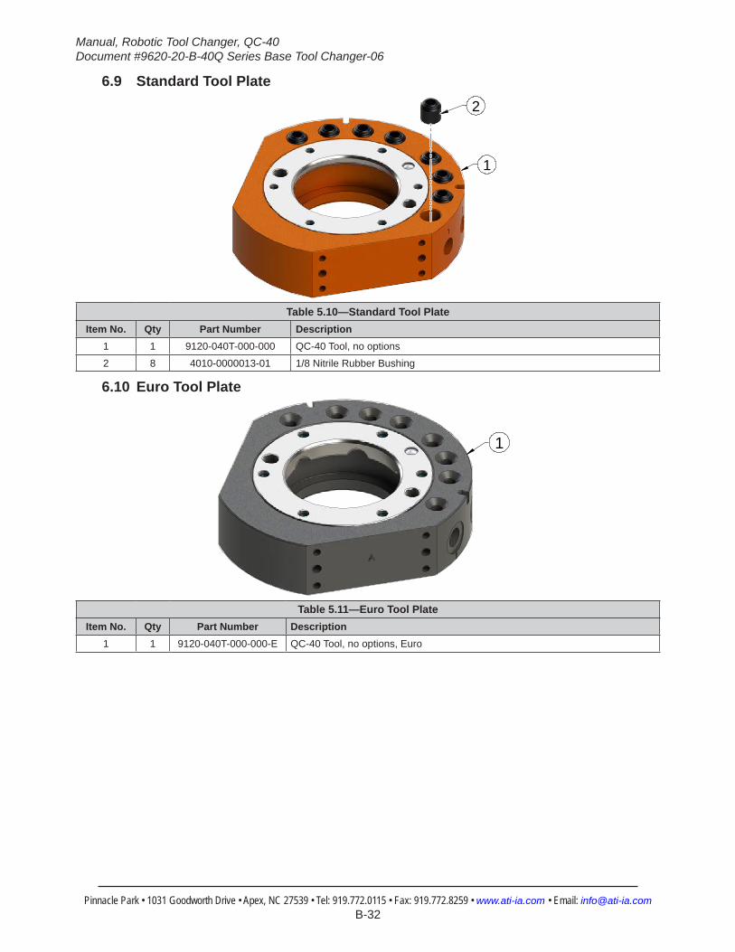
6.9 Standard Tool Plate
1
2
Table 5.10—Standard Tool Plate Item No. Qty Part Number Description
1 1 9120-040T-000-000 QC-40 Tool, no options
2 8 4010-0000013-01 1/8 Nitrile Rubber Bushing
6.10 Euro Tool Plate
1
Table 5.11—Euro Tool Plate Item No. Qty Part Number Description
1 1 9120-040T-000-000-E QC-40 Tool, no options, Euro

Manual, Robotic Tool Changer, QC‑40Document #9620‑20‑B‑40Q Series Base Tool Changer‑06
Pinnacle Park • 1031 Goodworth Drive • Apex, NC 27539 • Tel: 919.772.0115 • Fax: 919.772.8259 • www.ati‑ia.com • Email: info@ati‑ia.com B-33
7. SpecificationsTable 5.12—Master and Standard Tool Plates
Recommended Max Payload 110 lbs (50kg) The mass attached to the Tool Changer.Operating Temperature Range
-20–150°F(-30–66°C) Optimal operating temperature range.
Operating Pressure Range 60–100 psi(4.1–6.9 bar)
Locking mechanism supply pressure operating range. Supply to be clean, dry, and filtered to 50 micron or better.
Coupling Force @ 80 psi 1,270 lbs.(5,650 N) Axial holding force
Recommended Max Moment X-Y (Mxy)
Recommended Max Torque about Z (Mz)
2000 lbf-in226 (Nm)
2000 lbf-in226 (Nm)
Maximum recommended working load for optimum performance of the Tool Changer
Maximum recommended working torque for optimum performance of the Tool Changer
Positional Repeatability 0.0006”(0.015 mm) Repeatability tested at rated load at one million cycles.
Weight (coupled, no access.) 4.15 lbs (1.88 kg) Master 2.8 lbs.(1.27 kg)/Tool 1.35 lbs.(0.61 kg)Max. Recommended distance between Master and Tool plate
0.12 in.*(3.0 mm)
No-Touch locking technology allows the Master and Tool plates to lock with separation when coupling.* 80 psi needed at max. payload.
Sensor Information, signal name
L/U(Lock/Unlock)
Internal proximity sensors (2) with pigtails toindicate locking mechanism position.
Manual, Robotic Tool Changer, QC‑40Document #9620‑20‑B‑40Q Series Base Tool Changer‑06
Pinnacle Park • 1031 Goodworth Drive • Apex, NC 27539 • Tel: 919.772.0115 • Fax: 919.772.8259 • www.ati‑ia.com • Email: info@ati‑ia.com B-34
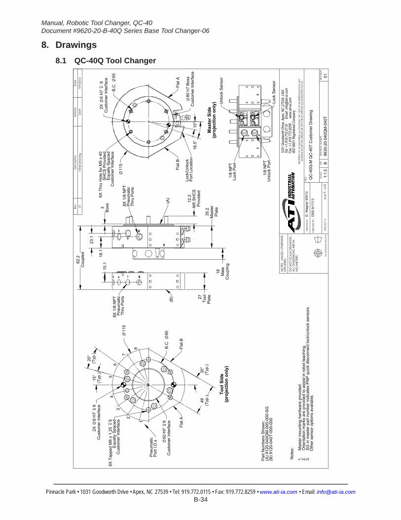
8. Drawings8.1 QC-40Q Tool Changer
3rd
AN
GLE
PRO
JEC
TION
27To
olP
late
3B
oss
18 Mal
eC
oupl
ing
35.2
Mas
ter
Pla
te
12.2
M5
SH
CS
Pro
vide
d
62.2
Cou
pled
15.
1 1
8.1
23.
1
8X 1
/8 N
PT
Pne
umat
icTh
ru P
orts
8X 1
/8 N
PT
Pne
umat
icTh
ru P
orts
(B)
(A)
2X
6 H
7 6
Cus
tom
er In
terfa
ce
B.C
. 65
11
5
80 h
7 B
oss
Cus
tom
er In
terfa
ce 1
8.5°
1
0°
Lock
/Unl
ock
Por
t Loc
atio
n
Flat
BFl
at A
6X T
hru
Hol
e fo
r M5
x 40
SH
CS
Pro
vide
dE
qual
ly S
pace
dC
usto
mer
Inte
rface
Mas
ter S
ide
(pro
ject
ion
only
)
2X
8 H
7 8
Cus
tom
er In
terfa
ce
115
B.C
. 80
50 H
7 6
Cus
tom
er In
terfa
ce
30°
(Typ
.)
15°
(Typ
.)
20°
(Typ
.)
49(T
yp.)
6X T
appe
d M
8 x
1.25
8
Equ
ally
Spa
ced
Cus
tom
er In
terfa
ce
Flat
AFl
at B
1
2
34
56
7
8
Pne
umat
icP
ort I
.D.s
Tool
Sid
e(p
roje
ctio
n on
ly)
1/8
NP
TLo
ck P
ort
1/8
NP
TU
nloc
k P
ort
Unl
ock
Sen
sor
Lock
Sen
sor
Par
t Num
bers
Sho
wn:
(A) 9
120-
040Q
M-0
00-0
00-S
G(B
) 912
0-04
0T-0
00-0
00
Not
es: Mas
ter m
ount
ing
hard
war
e pr
ovid
ed.
1.O
rient
atio
n m
arks
are
pro
vide
d to
ass
ist i
n ro
bot t
each
ing.
2.S
G in
mas
ter p
art n
umbe
r ind
icat
es P
NP
qui
ck d
isco
nnec
t loc
k/un
lock
sen
sors
.3.
Oth
er s
enso
r opt
ions
ava
ilabl
e.
Rev.
Des
crip
tion
Initi
ator
Dat
e
01In
itial
Dra
win
gD
AW
9/9/
2013
B1:
1.5
13
REVI
SIO
N
NO
TES:
UN
LESS
OTH
ERW
ISE
SPEC
IFIE
D.
DO
NO
T SC
ALE
DRA
WIN
G.
ALL
DIM
ENSI
ON
S A
RE IN
M
ILLIM
ETER
S.
DRA
WN
BY:
CHE
CKE
D B
Y:
D. W
agne
r 9/9
/13
DSS
9/1
7/13
TITLE SC
ALE
SIZE
DRA
WIN
G N
UMBE
R
PRO
JEC
T #
SHEE
T
O
F 96
30-2
0-04
0QM
-040
T01
PRO
PERT
Y O
F A
TI IN
DUS
TRIA
L A
UTO
MA
TION
, IN
C. N
OT
TO B
E RE
PRO
DUC
ED IN
AN
Y M
AN
NER
EXC
EPT
ON
ORD
ER O
R W
ITH P
RIO
R W
RITT
EN A
UTHO
RIZA
TION
OF
ATI.
1031
Goo
dwor
th Dr
ive, A
pex,
NC 27
539,
USA
Tel: +
1.919
.772.0
115
Em
ail: in
fo@ati
-ia.co
mFa
x: +1
.919.7
72.82
59
www
.ati-ia
.com
ISO
9001
Reg
ister
ed C
ompa
ny
QC
-40Q
-M Q
C-4
0T C
usto
mer
Dra
win
g
Manual, Robotic Tool Changer, QC‑40Document #9620‑20‑B‑40Q Series Base Tool Changer‑06
Pinnacle Park • 1031 Goodworth Drive • Apex, NC 27539 • Tel: 919.772.0115 • Fax: 919.772.8259 • www.ati‑ia.com • Email: info@ati‑ia.com B-35
3rd
AN
GLE
PRO
JEC
TION
11
5
89
2
6
7
123
4
10
13
1
10
14
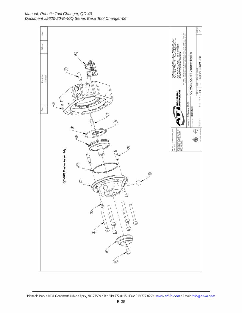
QC
-40Q
Mas
ter A
ssem
bly
Rev.
Des
crip
tion
Initi
ator
Dat
e
-Se
e Sh
eet1
--
B3:
42
3RE
VISIO
N
NO
TES:
UN
LESS
OTH
ERW
ISE
SPEC
IFIED
.
DO
NO
T SC
ALE
DRA
WIN
G.
ALL
DIM
ENSI
ON
S A
RE IN
M
ILLIM
ETER
S.
DRA
WN
BY:
CHE
CKE
D B
Y:
D. W
agne
r 9/9
/13
DSS
9/1
7/13
TITLE SC
ALE
SIZE
DRA
WIN
G N
UMBE
R
PRO
JEC
T #SH
EET
O
F 96
30-2
0-04
0QM
-040
T01
PRO
PERT
Y O
F A
TI IN
DUS
TRIA
L A
UTO
MA
TION
, IN
C. N
OT T
O B
E RE
PRO
DUC
ED IN
AN
Y M
AN
NER
EXC
EPT O
N O
RDER
OR
WITH
PRI
OR
WRI
TTEN
AUT
HORI
ZATIO
N O
F A
TI.
1031
Goo
dwor
th Dr
ive, A
pex,
NC 27
539,
USA
Tel: +
1.919
.772.0
115
Em
ail: in
fo@ati
-ia.co
mFa
x: +1
.919.7
72.82
59
www
.ati-ia
.com
ISO
9001
Reg
ister
ed C
ompa
ny
QC
-40Q
-M Q
C-4
0T C
usto
mer
Dra
win
g
Manual, Robotic Tool Changer, QC‑40Document #9620‑20‑B‑40Q Series Base Tool Changer‑06
Pinnacle Park • 1031 Goodworth Drive • Apex, NC 27539 • Tel: 919.772.0115 • Fax: 919.772.8259 • www.ati‑ia.com • Email: info@ati‑ia.com B-36
3rd
AN
GLE
PRO
JEC
TION
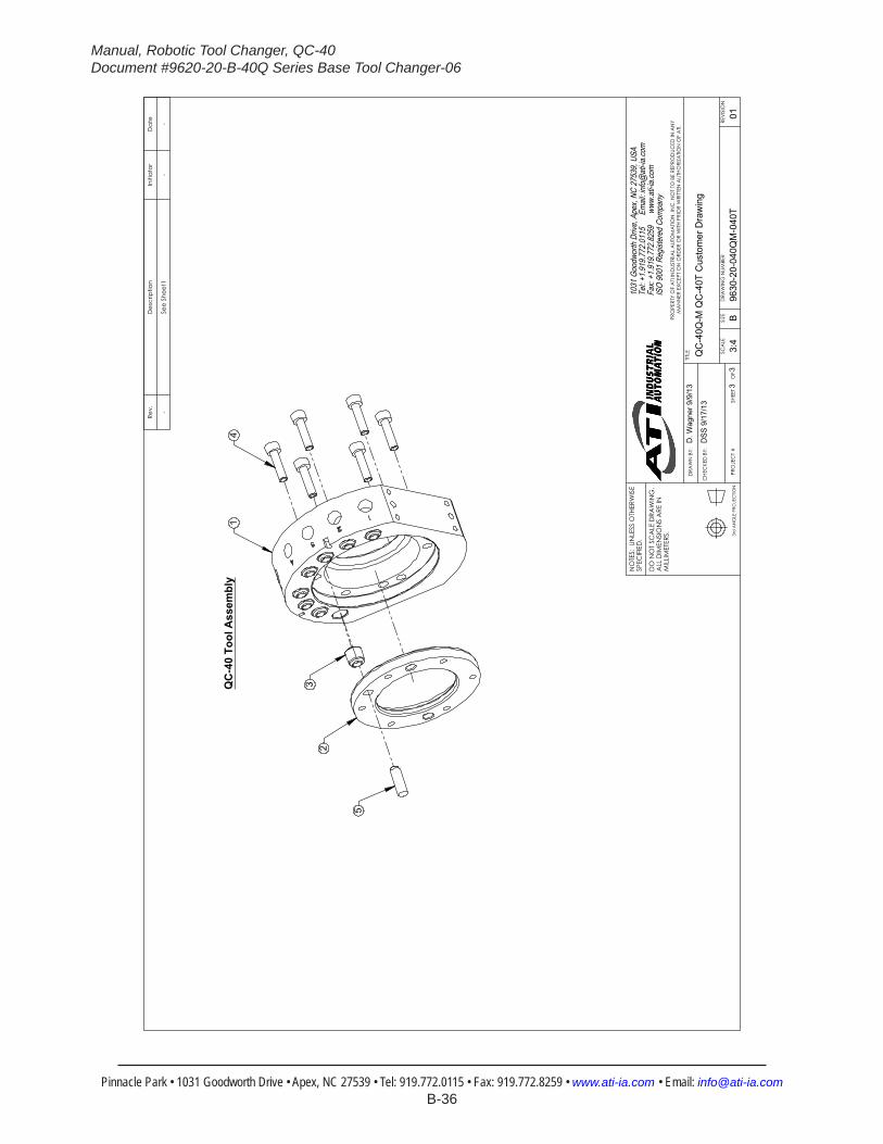
QC
-40
Tool
Ass
embl
y
5
23
14
Rev.
Des
crip
tion
Initi
ator
Dat
e
-Se
e Sh
eet1
--
B3:
43
3RE
VISI
ON
NO
TES:
UN
LESS
OTH
ERW
ISE
SPEC
IFIE
D.
DO
NO
T SC
ALE
DRA
WIN
G.
ALL
DIM
ENSI
ON
S A
RE IN
M
ILLIM
ETER
S.
DRA
WN
BY:
CHE
CKE
D B
Y:
D. W
agne
r 9/9
/13
DSS
9/1
7/13
TITLE SC
ALE
SIZE
DRA
WIN
G N
UMBE
R
PRO
JEC
T #
SHEE
T
O
F 96
30-2
0-04
0QM
-040
T01
PRO
PERT
Y O
F A
TI IN
DUS
TRIA
L A
UTO
MA
TION
, IN
C. N
OT
TO B
E RE
PRO
DUC
ED IN
AN
Y M
AN
NER
EXC
EPT
ON
ORD
ER O
R W
ITH P
RIO
R W
RITT
EN A
UTHO
RIZA
TION
OF
ATI.
1031
Goo
dwor
th Dr
ive, A
pex,
NC 27
539,
USA
Tel: +
1.919
.772.0
115
Em
ail: in
fo@ati
-ia.co
mFa
x: +1
.919.7
72.82
59
www
.ati-ia
.com
ISO
9001
Reg
ister
ed C
ompa
ny
QC
-40Q
-M Q
C-4
0T C
usto
mer
Dra
win
g