Embed Size (px)
Citation preview

Manual ProtoMat S62 English, version 4.0
LPKF Laser & Electronics AGOsteriede 7D-30827 Garbsen
Telephone : ++ 49 - 51 31 - 70 95 - 0 Telefax : ++ 49 - 51 31 - 70 95 - 90eMail : [email protected] : http: //www.lpkf.de

2 Version 4.0 Rev.: 29.7.05 ProtoMat S62
Copyright (C) 2005 LPKF AGNo part of this document may be reproduced or transmitted or used for any purpose without the express written permission of LPKF. The information contained in this document is subject to change without prior notification. LPKF assumes no liability for the use of this document. In particular for damage resulting from information, which is present, not present or erroneous. Trademarks: HP-GL is a trademark of the Hewlett-Packard Corp.All other trademarks are the property of the specific proprietor.
Item number: 115808

ProtoMat S62 Version 4.0 Rev.: 29.7.05 3
Notes on this ManualThe information contained in this document is subject to change without previous notice. No part of this document may be reproduced or transmitted for any purposes in any form without express written permission of LPKF AG. All efforts were made to ensure that this document is as accurate as possible and that the information contained therein is complete. Nevertheless, LPKF AG cannot assume any liability for its use or for any violations of patent or other rights held by third parties resulting there from.
The operator of the machine is responsible for ensuring that the following points are observed. Ensure that
• the machine is used only for its intended purpose.
• the machine is operated only in a perfect functional condition and particularly that the safety equipment is checked regularly for proper function.
• required personal protective equipment for the operating, maintenance and repair personnel is available and used.
• the operating instructions are always kept at the location where the machine is operated and are in a legible and complete condition.
• only sufficiently qualified and authorized personnel operate, service and repair the machine.
• this personnel is trained regularly on all questions regarding labor safety and environmental protection as well as is familiar with the operating instructions and particularly the safety precautions contained therein.
• all safety and warning information attached to the machine is not removed and remains legible.

4 Version 4.0 Rev.: 29.7.05 ProtoMat S62
I. OutlineThis Manual is subdivided into the following chapters:
1. Introduction 2. Intended use 3. Safety notes 4. Scope of delivery 5. Layout of machine 6. Bringing into service 7. BoardMaster User Surface 8. Introduction to the Basic Functions of the ProtoMat S62 9. BoardMaster Functions 10.Menu Bar 11.Operating procedures 12.Practical tips 13.Other BoardMaster Functions 14.Special Applications 15.Appendix 16.Options 17.Technical Data 18.Declaration of conformity 19.Index
II. Conventions used in this manual
Bold text is used to emphasize important information.
Illustrations are numbered. Example: Fig. 5
› Prompts for actions are identified with an arrow.
Italic sections are used to indicate the reactions consequent on an action.
Word printed in italics mark proper names.
Key inscriptions and menu terms are printed in BOLD CAPITALS.
III. Notes on the symbols used
Danger! This symbol is used to highlight danger to life or health.
Caution! This symbol is used to identify hazards which may cause damage.

ProtoMat S62 Version 4.0 Rev.: 29.7.05 5
Note! This symbol is used for notes intended to help you avoid faults in operation or to help you improve your procedures.
Machine greenhorn:This symbol indicates important tips and information for those not already familiar with LPKF milling technology.
IV. Terminology
Copper laminate : Special extremely thin base material used for pressing multilayers.
Base material : Circuit board material coated with copper foil
Solder resist foil : Special foil with cutouts for solder connections on a circuit board.
BoardMaster : Machine control software.
CircuitCAM : Software for data processing
V. Target GroupThis manual is intended for personnel who already possess basic knowledge of production of circuit boards for the electronic sector.
VI. Intended UseThe machine described in this manual is intended exclusively for milling and drilling standard commercial circuit board materials in the electronic industry. Any other type of use of the machine is expressly prohibited.

6 Version 4.0 Rev.: 29.7.05 ProtoMat S62
Contents
1.0 Introduction. . . . . . . . . . . . . . . . . . . . . . . . . 11
2.0 Intended Use . . . . . . . . . . . . . . . . . . . . . . . . 13
3.0 Safety Notes . . . . . . . . . . . . . . . . . . . . . . . . 14
4.0 Scope of Delivery . . . . . . . . . . . . . . . . . . . . 16
4.1 Accessories (available as option) . . . . . . . . . . . . . .16
5.0 Layout of Machine . . . . . . . . . . . . . . . . . . . 17
5.1 Initial Setup. . . . . . . . . . . . . . . . . . . . . . . . . . . . . . .17
5.2 Orientation Axis / Positions . . . . . . . . . . . . . . . . . .20
5.3 Machine Components and Connections . . . . . . . .21
5.4 Serial Interface(s) / USB Connection . . . . . . . . . . .22
5.5 Functional Units . . . . . . . . . . . . . . . . . . . . . . . . . . .24
5.5.1 The Machining Head . . . . . . . . . . . . . . . . . . . . . . 245.5.1.1 Machining Spindle with Collet . . . . . . . . . . . . . . . . . 25
5.5.2 Working Depth Limiter . . . . . . . . . . . . . . . . . . . . . 25
6.0 Bringing into Service . . . . . . . . . . . . . . . . . 26
6.1 Installation . . . . . . . . . . . . . . . . . . . . . . . . . . . . . . .26
6.1.1 System Prerequisites . . . . . . . . . . . . . . . . . . . . . . 26 6.1.2 Installation . . . . . . . . . . . . . . . . . . . . . . . . . . . . . . 26 6.1.3 Directories Generated During Installation . . . . . . 28
6.2 Installation of the USB driver . . . . . . . . . . . . . . . . .28
6.3 Introduction. . . . . . . . . . . . . . . . . . . . . . . . . . . . . . .28

ProtoMat S62 Version 4.0 Rev.: 29.7.05 7
6.3.1 HOME Position and Reference Hole System . . . 29
6.4 Switching On the Circuit Board Plotter . . . . . . . . . .30
6.4.1 Starting BoardMaster. . . . . . . . . . . . . . . . . . . . . . 30 6.4.2 Plotter Ready. . . . . . . . . . . . . . . . . . . . . . . . . . . . 31 6.4.3 Wait Message . . . . . . . . . . . . . . . . . . . . . . . . . . . 32
6.5 Switching Off the Circuit Board Plotter . . . . . . . . . .33
7.0 BoardMaster User Surface . . . . . . . . . . . . 34
7.1 Function Bar . . . . . . . . . . . . . . . . . . . . . . . . . . . . . .35
7.2 Brief Summary of Function Bar . . . . . . . . . . . . . . .35
7.2.1 Status information . . . . . . . . . . . . . . . . . . . . . . . . 36
8.0 Introduction to the Basic Functions of the ProtoMat S62 . . . . . . . . . . . . . . . . . . . . . . . . 38
8.1 Creating a New Reference Hole System . . . . . . . .39
8.2 Preparing and putting on base material . . . . . . . . .40
8.3 Working with Production Data and Phases . . . . . .42
9.0 BoardMaster Functions. . . . . . . . . . . . . . . 50
9.1 Changeable Settings . . . . . . . . . . . . . . . . . . . . . . .50
9.2 Positioning Functions . . . . . . . . . . . . . . . . . . . . . . .50
9.3 Control Functions for Manual Control. . . . . . . . . . .51
9.4 Selection functions . . . . . . . . . . . . . . . . . . . . . . . . .52
9.5 Control Functions for Production Phase. . . . . . . . .53
9.6 Camera Functions (only for S62 with camera option)54

8 Version 4.0 Rev.: 29.7.05 ProtoMat S62
9.7 Tool Holder . . . . . . . . . . . . . . . . . . . . . . . . . . . . . . .54
10.0 Menu Bar . . . . . . . . . . . . . . . . . . . . . . . . . . 56
10.1 Go To Menu . . . . . . . . . . . . . . . . . . . . . . . . . . . . .56
10.2 CONFIGURATION Menu . . . . . . . . . . . . . . . . . . .57
10.2.1 Serial Interface . . . . . . . . . . . . . . . . . . . . . . . . . . 57 10.2.2 Machine Settings . . . . . . . . . . . . . . . . . . . . . . . . 59 10.2.3 Tool Parameter. . . . . . . . . . . . . . . . . . . . . . . . . . 61 10.2.4 Heads Dialog Box. . . . . . . . . . . . . . . . . . . . . . . . 63 10.2.5 Adjust Camera Offset . . . . . . . . . . . . . . . . . . . . . 64 10.2.6 Phase... - Production Phases. . . . . . . . . . . . . . . 65 10.2.7 Defining the Base Material Size . . . . . . . . . . . . . 67
10.3 File Menu . . . . . . . . . . . . . . . . . . . . . . . . . . . . . . .69
10.4 Edit Menu . . . . . . . . . . . . . . . . . . . . . . . . . . . . . . .70
10.4.1 Assigning Tools . . . . . . . . . . . . . . . . . . . . . . . . . 70 10.4.2 Placing Projects . . . . . . . . . . . . . . . . . . . . . . . . . 73 10.4.3 Select Tools . . . . . . . . . . . . . . . . . . . . . . . . . . . . 75
10.5 Reload Dialog Box . . . . . . . . . . . . . . . . . . . . . . . .75
10.6 View Menu . . . . . . . . . . . . . . . . . . . . . . . . . . . . . .77
10.7 Selecting Production Phase . . . . . . . . . . . . . . . . .78
10.8 Automatic Tool Change . . . . . . . . . . . . . . . . . . . .79
11.0 Operating Procedures . . . . . . . . . . . . . . . 81
11.1 Fastening the Base Material . . . . . . . . . . . . . . . . .81
11.2 The tools . . . . . . . . . . . . . . . . . . . . . . . . . . . . . . . .82
11.3 Drilling. . . . . . . . . . . . . . . . . . . . . . . . . . . . . . . . . .83
11.4 Insulation Milling . . . . . . . . . . . . . . . . . . . . . . . . . .83
11.5 Contour Milling in Circuit Board Material . . . . . . .84

ProtoMat S62 Version 4.0 Rev.: 29.7.05 9
11.6 Milling Wide Insulation Channels . . . . . . . . . . . . .85
11.7 Cleaning Circuit Boards . . . . . . . . . . . . . . . . . . . .86
12.0 Practical Tips . . . . . . . . . . . . . . . . . . . . . . 87
13.0 Other BoardMaster Functions . . . . . . . . 89
13.1 Learning Fiducial (Option) . . . . . . . . . . . . . . . . . .89
13.1.1 Adjusting Milling Depth . . . . . . . . . . . . . . . . . . . 92 13.1.2 Drilling Reference Holes in Base Material . . . . . 93 13.1.3 Special Features . . . . . . . . . . . . . . . . . . . . . . . . 95
13.1.3.1 Tool box dialog box. . . . . . . . . . . . . . . . . . . . . . . . . 9513.1.3.2 Service password dialog box . . . . . . . . . . . . . . . . . 96
14.0 Special Applications . . . . . . . . . . . . . . . . 98
14.1 Front Panel Engraving . . . . . . . . . . . . . . . . . . . . .98
14.2 Milling Solder Resist Foils . . . . . . . . . . . . . . . . . .98
15.0 Appendix . . . . . . . . . . . . . . . . . . . . . . . . 100
15.1 Switching over the device voltage . . . . . . . . . . .100
15.2 Maintenance. . . . . . . . . . . . . . . . . . . . . . . . . . . .103
15.2.1 X Axis, Y-Axis and Z Axis . . . . . . . . . . . . . . . . 103 15.2.2 Maintenance on Working Depth Limiter . . . . . 104 15.2.3 Maintenance instruction for Machining Head . 106
15.3 Checking and adjusting the tool positions by means of the camera . . . . . . . . . . . . . . . . . . . . . . . . . . . .107
15.4 Checking and adjusting tool positions without camera108
15.5 The Teach-In Dialog Box . . . . . . . . . . . . . . . . . .109
16.0 Options . . . . . . . . . . . . . . . . . . . . . . . . . . 112

10 Version 4.0 Rev.: 29.7.05 ProtoMat S62
16.1 Installing the camera . . . . . . . . . . . . . . . . . . . . .112
16.2 Mounting the Vacuum Table . . . . . . . . . . . . . . . .114
16.3 Spring setting at the machining head . . . . . . . . .116
17.0 Technical Data . . . . . . . . . . . . . . . . . . . . 118
18.0 Declaration of Conformity . . . . . . . . . . . 119
19.0 Index . . . . . . . . . . . . . . . . . . . . . . . . . . . . 121

Introduction
ProtoMat S62 Version 4.0 Rev.: 29.7.05 11
1.0 Introduction
The machine described in this manual is a circuit board plotter suitable for producing circuit board prototypes and engraved films. It consists basically of a base plate, an X/Y motion system and a machining head. This machining head can be moved along both axes with the aid of the X/Y motion system. The machining head can also be lowered. This results in two basic processing possibilities. First, a channel can be milled with a milling cutter in a piece of base material fastened to the base plate by moving the lower machining head. Second, a hole can be drilled in the base material by lowering the machining head when it is standing still and a drill installed.
This circuit board plotter offers very high precision in machining and high machining speed. Almost completely automatic processing is possible due to other special functions like fully automatic tool change and the adjustable depth with which the tool penetrates the base material during drilling, which can be set via the software. All this helps to minimize the effort required for operation in small series production. Another special feature is the integrated vacuum table which enables the processing of soft and flexible substrates (special PCB materials).
The machine is controlled and operated almost completely by the BoardMaster software. Always read this manual carefully before starting work with the machine. After unpacking, set up your circuit board plotter on a suitable table (see chapter „Initial Setup“ on page 17 for a description) and inspect all of the components described in the following chapters precisely, i.e. familiarize yourself with the mechanical control possibilities. This will make it easier when you then start up the machine in combination with the software with the aid of the quick start instructions or the BoardMaster chapters.
LPKF BoardMaster 5.0 for WindowsTM is a program for automatic control of HP-GL-compatible LPKF circuit board plotters.
LPKF BoardMaster is capable of reading in, displaying and processing production data in LMD format (generated in LPKF CircuitCAM) as well as production data generated in HP-GL format
BoardMaster takes over complete control of the circuit board plotter. The WYSIWYG (What You See Is What You Get) display for the data to be processed, manual control of the circuit board plotter on the Windows surface as well as the present tool library with all required information ensures virtually complete automation of circuit board prototype production.
This Manual shows you the path from LMD/HP-GL circuit board data generated by CircuitCAM or other programs, over job preparation right up to completion of the circuit board prototypes with the circuit board plotter.
The Manual introduces the basic control possibilities of BoardMaster step by step, allowing you to quickly complete your first circuit board in a simple manner.
Basic use of the Windows surface is not covered in this manual. If you are not familiar with the use of the various Windows objects, please first refer to your Windows documentation.

Introduction
12 Version 4.0 Rev.: 29.7.05 ProtoMat S62
In order to ensure that any possible guarantee claims are honored, always follow the instructions in this manual before starting up the machine. Machines exported to other EU countries are subject to the guarantee terms in that country.
Now we hope you enjoy familiarizing yourself with your circuit board plotter.

Intended Use
ProtoMat S62 Version 4.0 Rev.: 29.7.05 13
2.0 Intended UseThe machine described in this manual is exclusively designed and constructed for the machining of commercially approved materials for the production of printed circuit boards or front plates. This comprises especially the following working steps:
Machining of all one-sided and double-sided board types in the usual packing density (FR3, FR4, FR5, G10), flexible substrates, RF substra-tes, drilling test adapters, structuring film patterns, producing solder fra-mes for PCB assembly, SMD fine line technology, contour-milling, engraving of front panels or labels, depth milling of rigid or flexible boards, depaneling and reworking of populated and unpopulated boards, machining of housings and multilayers up to 8 layers in combi-nation with MiniContac III and MultiPress-II.
Any other use is explicitely forbidden! Danger of damage to material or personal injury, and any guarantee claims are excluded!

Safety Notes
14 Version 4.0 Rev.: 29.7.05 ProtoMat S62
3.0 Safety Notes
Danger: To ensure safe work with the circuit board plotter, the user should read this Manual as well as the enclosed documentation and particularly the safety precautions in bold face print!
• Keep your workplace orderly. Disorder at the workplace increases the danger of an accident!
• Take surrounding influences into consideration: Do not subject the electric machine to water or water spray. Do not use the circuit board plotter in moist or wet surroundings. Provide for good illumination. Never use the machine in areas endangered by fire or explosion.
• Keep children away from the working area! Ensure that children cannot touch the machine or connection line!
• Wear suitable work clothing! Do not wear wide clothing or jewelry. This can be caught by moving parts!
• Wear a hair net if you have long hair! Otherwise, your hair can get caught in a rotating tool!
• Care for your machine and the accessories properly and observe the maintenance instructions! Check the plug and cable regularly and if damaged have replaced by an authorized electrician!
• Before any type of maintenance or cleaning work on the machine, disconnect the power plug!
• Always be attentive! Observe your work and proceed rationally. Do not use the machine if you are unconcentrated!
• Always work with the vacuum on! Dusts resulting during operation of the machine may pose a health hazard and must therefore be evacuated!
• Check the machine regularly for damage! Ensure that all parts are installed correctly and that all conditions are fulfilled for proper operation as intended.
• Use only accessories and add-on equipment specified in the operating instructions or recommended or prescribed by the manufacturer! Use of other tools or accessories can cause damage to the machine or pose an injury hazard for the user!
• Have the machine repaired by authorized personnel! The circuit board plotter fulfills all applicable safety regulations. Repair should be performed only by qualified personnel using genuine parts, because improper repairs can pose an injury hazard for the user
• Caution when closing the machine hood! Danger of injury to hands!
• Never reach into the machine while it is running! • Caution! Machine changes motion speed automatically
during operation!

Safety Notes
ProtoMat S62 Version 4.0 Rev.: 29.7.05 15
• iChange tools only with the machining head spindle stopped! Injury hazard!
• When changing tools manually, always insert tool into chuck against stop!
• iWhen performing manipulations on the machine, never operate the controlling PC simultaneously.
• Never reach into the traversing range of the running machine! The XY positioning systeem may move very fast. Fot this reason the handling also of auxiliary tools in the area of the base plate is strictly prohibited. Shear force may e.g. cut of fingers
• The safety of the machine can no longer be guaranteed if modifications are made to the machine by the user and the guarantee is invalidated!
• Observe that some materials can produce carcinogenic dust or dangerous gases during processing. Obtain information from material suppliers.
• Eating, drinking or smoking while working with the circuit board plotter is prohibited! The danger exists of ingesting toxic substances through the mouth! Never leave food or beverages open in the workroom (dust deposit!).
• When using chemicals, please observe the instructions on the containers or any separate safety data sheets!
• Wear suitable protection gloves during the exchange of material of the machine base plate. Danger of cutting due to sharp edges of the metall supports!
• When the cover is opened the present command is executet and then the machine will stop and no more commands can be given!
• Ensure that your computer is properly connected to the line power and to the circuit board plotter!
• Ensure that no one is present in the hazard area of the circuit board plotter during data transfer between BoardMaster and the circuit board plotter!
• Ensure that no one can enter the hazard area of the circuit board plotter and come into contact with the tools during operating phases controlled by BoardMaster!
• Ensure that it is not possible for unauthorized persons to operate BoardMaster when working with the circuit board plotter, for example during manual tool change or alignment of the base material!
• In the event of an emergency, shut off the circuit board plotter and PC connected to the circuit board plotter immediately!
• Also observe other safety precautions in this manual!

Scope of Delivery
16 Version 4.0 Rev.: 29.7.05 ProtoMat S62
4.0 Scope of Delivery
• 1 Machine unit LPKF ProtoMat S62 with integrated electronic circuitry
• 1 Connection cable machine - PC (USB or serial)
• 1 Set accessories (foot of the working depth limiter, adhesive tape, various Torx tools, 5 reference hole pins, tweezers, brush, 2 red reference hole strips, 2 reference hole drills 2.95 mm, set of fuses)
• 1 Power cable
• 1 Piece base material (fixed on machine base plate)
• 1 Manual ProtoMat S62 machine and software BoardMaster
• 1 CD ROM with software program BoardMaster
• 1 Manual software CircuitCAM
• 1 Pre-assembled hood
• 1 UUSB cable (from mid of July 2005 on)
• 1 USB repeater (from mid of July 2005 on)
4.1 Accessories (available as option)• 1 Vacuum system with fine mesh filter and integratetd automatic
switch, adjustable exhaust power and automatic filter control. The vacuum system is switeched on and off via the machining spindle.
• Danger: The fine filter is required particularly for processing materials containing fiber glass such as FR4 base material! Otherwise, the hazard exists of carcinogenic dust particles escaping!!
• Vision System
Camera-based positioning system for fiducial recognition
• LPKF ProConduct
System for through-plating with paste
• Vacuum table
System for fixing rigid or flexible materials free from distortion or warp

Layout of Machine
ProtoMat S62 Version 4.0 Rev.: 29.7.05 17
5.0 Layout of Machine
5.1 Initial Setup
› Lift the cover of the cardboard box (1 in figure below) and remove the cardboard below
› Remove the software package and the manuals.
› Pull the styrofoam parts (3) at the side upward out of the box and lift the cardboard sidewalls (2) .
› Remove the protective foil.
› Put the circuit board plotter on a horizontal support capable of bearing the load.
Figure 1: Cardboard packing of the ProtoMat S62
Note: The machine should be positioned on a level and solid surface to prevent malfunctions and erroneous operation!
› Remove securing devices (see 1, 2 and 3 in following figure) before switching on the plotter !!! Also remove any residual glue remaining on the board.
Caution! Shoud you switch on the plotter without having removed the transport securing devices first, we will not accept any guaran-tee claims for resulting damage!!!
1- Top cover of cardboard machine packing 2- Cardboard sidewalls (or frame)3-Styrofoam protection at the sides4- Place for manuals
1 32 34

Layout of Machine
18 Version 4.0 Rev.: 29.7.05 ProtoMat S62
Figure 2:Transport sealings
› After the removal of all the transport sealings, the foot of the working depth limiter (4 in figure above, contained in the accessories set supplied with the delivery) has to be inserted in the working depth limiter underneath the mill/drill head! To do this, hold the machining head tight with your other hand!
Note:If the software BoardMaster should already have been started when the foot is being inserted and should the machining head not be held firmly, then an error message appears as the machining head is moving outside of the movement border. !
Figure 3: ProtoMat S62 with cover
1
2
34
1- Vacuum hose2- Machining head3- Tool magazine4- Movable table to fix base material
31
2
3
4

Layout of Machine
ProtoMat S62 Version 4.0 Rev.: 29.7.05 19
› Then connect the LPKF ProtoMat machine to the computer (COM 1, COM 2, or USB) with the Connection cable (Sub-D to RJ45 Connec-tor). Remove the protection covers from the connectors and connect the RJ45 Connector with socket named“RS232/CAN“ and the Sub-D Connector to COM1 or COM2 on the PC or the USB cable to the USB sokket.
› Connect the power cable on the LPKFProtoMat machine to the line power. To do this, pull the power cable from the backside of the machine to the front until it reaches the main switch.
Figure 4: Mains connection, main switch, voltage switch-over
› Screw the vacuum hose in the connecting piece (counter-clockwise) and attach this to the adapter, see figure below.
Figure 5: Connection vacuum system
1- Mains connection, main switch and switching the voltage
1
1 Exhaust adapter 3 Vacuum hose2 Connecting piecet
1
23

Layout of Machine
20 Version 4.0 Rev.: 29.7.05 ProtoMat S62
› Attach the loose vacuum hose over the circuit board plotter to the appropriate connection on the machining head (position 5 in figure 1 on page 17).
› Connect the control cable for the exhaust system on the rear of the machine (see figure 5.3 on page 21)
Note: Please save all transport retainers as well as the packaging for re-use if the machine is transported again.
5.2 Orientation Axis / Positions The machining head can move along 3 axes. These axes are called the X, Y and Z axes. Definition of the axes is important for you during operation so that you always know where the table is moving. In the BoardMaster software, the motion paths are described exclusively according to these axis designations.
Figure 6: Orientation axis
1- Pause position: The machine is moved to this point to install or turn the material to be processed 2- HOME position3- Zero position: The macine is moved to this point after switching on (machining head on the left, table to the
front).
X-Axis
Y-Axis
Z-Axis: Lifting/lowering the machining head
1
2
3
Z-Axis

Layout of Machine
ProtoMat S62 Version 4.0 Rev.: 29.7.05 21
5.3 Machine Components and Connections
Description of the front view:
Figure 7: Front view LPKF ProtoMatS62
Description of rear view:
Figure 8: Rear view, connections
1- Hood 4- Tool magazine2- Vacuum hose 5- Displaceable machine table3-Machining head
1
2
3
4
5
1- Mains cable 5- Serial connection (RS232/CAN - connection socket
2- Connecting cable camera - PC (option) 6-Connection hood 3-Status display „Ready for operation“ 7-Control cable for vacuum system4- USB cable 8- Ports 1 to 4
1 2 3 4
13
5 6 7 8

Layout of Machine
22 Version 4.0 Rev.: 29.7.05 ProtoMat S62
In the following figure you see how tools are placed in the tool magazine. For the order and the exact position of the tools please refer to the corresponding recommendation in the BoardMaster chapter:
Figure 9: Tools in tool magazine
5.4 Serial Interface(s) / USB ConnectionThe SERIAL1 is connected to a serial interface of the computer by means of the supplied null modem cable.
Wiring of the connecting cable is as follows:
The cable screening protection is connected only on the side of the PC (socket).
The following parameters must be observed:
Note: the serial interface at the PC is configured under Windows in the system control.
Baud rate: 57600 Parity: NoneData bit: 8Stop bit: 1Flow control (Windows XP): HardwareFIFO-buffer: on (max. speed)

Layout of Machine
ProtoMat S62 Version 4.0 Rev.: 29.7.05 23
Alternatively the connection can be done using the USB connection. Connect the USB cable with the USB sockets of the circuit board plotter and the PC. The optional camera can only be connected to a USB 2.0 port.
Note: USB can only be used via the LPKF USB repeater! For the installation of the USB driver see „Installation of the USB driver“ on page 28
Figure 10:Block diagram USB connection

Layout of Machine
24 Version 4.0 Rev.: 29.7.05 ProtoMat S62
5.5 Functional Units
5.5.1 The Machining Head
The machining head has several tasks. It provides the guidance and mounting for
• the spindle
• the stepping motor for the automatic milling depth adjustment
• the camera for fiducial recognition (option)
Moreover, the working depth limiter is located at the bottom of the machining head. It limits to which depth the drilling or milling tool penetrates the base material.
Figure 11: Machining head front view
1- Vacuum hose 6- Camera option: camera illumination2- Mounting plate for exhaust hose and
cable hose 7- Milling depth limiter (foot)
3- Camera option: holding block for camera
8- Spring adjusmtent pressure force
4- Camera option: aperture and focus setting of the camera
9- Connection head illumination
5- Camera option: mounting plate for exhaust hose and cable hose
10- Knurled screw for adjusting the milling depth
6
7
8
1
2
3
4
5
9
10
Layout of Machine
ProtoMat S62 Version 4.0 Rev.: 29.7.05 25
5.5.1.1 Machining Spindle with Collet
The machining spindle drives the machining tools, while the collet is responsible for their firm and precise location. The collet is firmly mounted on the machining spindle and from the outside only the tool opening can be seen (1 in following figure).
With this circuit board plotter the collet of the machining spindle is actua-ted automatically.
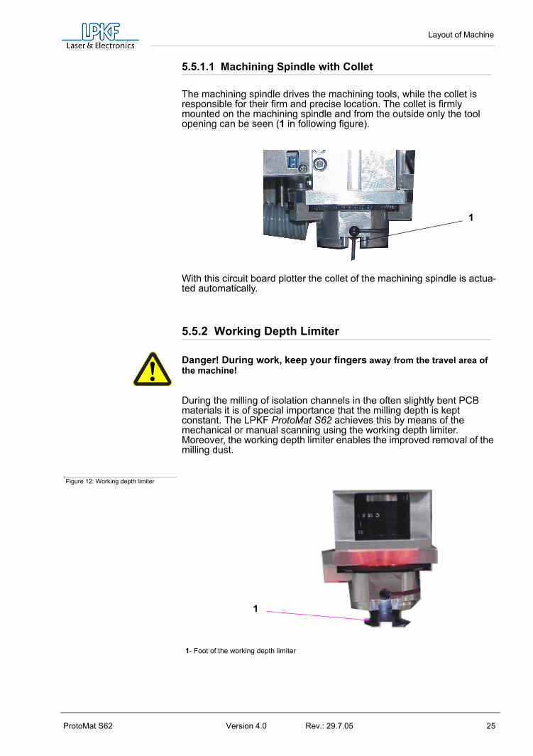
5.5.2 Working Depth Limiter
Danger! During work, keep your fingers away from the travel area of the machine!
During the milling of isolation channels in the often slightly bent PCB materials it is of special importance that the milling depth is kept constant. The LPKF ProtoMat S62 achieves this by means of the mechanical or manual scanning using the working depth limiter.Moreover, the working depth limiter enables the improved removal of the milling dust.
Figure 12: Working depth limiter
1
1- Foot of the working depth limiter
1
Bringing into Service
26 Version 4.0 Rev.: 29.7.05 ProtoMat S62
6.0 Bringing into Service
This chapter describes the switching-on procedure of your circuit board plotter. Some operating steps are explained with the help of the BoardMaster software. Therefore it is necessary that you install this software first on the PC with which the circuit board plotter is to be controlled. Connect the circuit board plotter to the corresponding PC (see „Initial Setup“ on page 17) and install the BoardMaster software on the corresponding PC (see following chapter)!
Observe the specified temperature range for operation of 15-25°C (59-77°F)!
6.1 Installation
6.1.1 System Prerequisites
The minimum system prerequisites for installation of BoardMaster are:
• Pentium Processor 1500 MHz or faster• 256 MB main memory (512 MBytes recommended)• XGA graphic card (recommended display resolution 1024 x 768
pixels) • Microsoft Windows 2000/XP• 16 x CD ROM drive, DVD-drive is recommended for optional DVD
for training• RS 232 interface and USB 2.0 for camera option
BoardMaster requires approx. 40 MB of free hard disk capacity for installation.
6.1.2 Installation
As soon as you have inserted the CD in the PC drive and if the autostart function of this drive is activated, the CD browser will start automatically. Its menu guidance will lead you through the installation of the LPKF pro-grams.If autostart is not activated on your PC, start the CD browser by double-clicking on the file SETUP.EXE.

Bringing into Service
ProtoMat S62 Version 4.0 Rev.: 29.7.05 27
Figure 13: Component selection
During installation, the appropriate initialization files are assigned to BoardMaster by selection of the circuit board plotter. The setup initialization files (*.MCH) contain information on the circuit board plotter used (resolution, max. speed, motion range, etc.), the tool libraries to be used and production phases. These points are treated in detail in the following chapters.
Note for update customers: The initialization file (*.INI) for your existing BoardMaster version is copied during installation of the update so that your user-specific settings are not lost.
New and update installation:
During installation of BoardMaster, the following window appears:
Figure 14: Component Selection
Select NEW, FIRST INSTALLATION if you are installing BoardMaster and your circuit board plotter for the first time. The setup program will request you to place the configuration CD supplied with the circuit board plotter and containing the specific INI file in the CD-ROM drive.

Bringing into Service
28 Version 4.0 Rev.: 29.7.05 ProtoMat S62
If you do not want to use this initialization file (*.INI), e.g. test installation without plotter connected, press <ESC> when Setup requests you to insert the configuration diskette. The Setup program then installs BoardMaster with standard settings.
Select UPDATE INSTALLATION if the Setup program is to add your present initialization file (*.INI) to your update installation. You will then be requested to select the directory containing the INI file. Here, you can press <ESC> to install BoardMaster with standard settings.
6.1.3 Directories Generated During Installation
During installation, the installation program generates a directory “C\Program files\LPKF50", for storing the programs and other required files as a standard feature.
The following subdirectories are created in the directory “LPKF50" for BoardMaster:
• BMaster contains the program files for BoardMaster as well as all required configuration files.
• Data contains the data files for BoardMaster. This is the standard directory where all data generated by CircuitCAM is stored.
• cfg_* Subdirectories for configuration scripts
After installation of BoardMaster, the Start menu contains a new program group “LPKF Laser & Electronics“, as well as a new linkage on your Windows desktop.
6.2 Installation of the USB driverThe USB drivers for the SMCU II of the ProtoMat S62 will be copied to the PC after BoardMaster has been installed.
› First install BoardMaster and then connect the ProtoMat S62 to the computer via USB.
After the ProtoMat S62 is switched on WINDOWS asks for the drivers for „SMCU II“.
› Use the WINDOWS USB setup to have the drivers copied from the directory C:\programs\LPKF50\BMasterusb_drv.
6.3 IntroductionThis and the following chapters provide basic information on the opera-ting principles and a first impression of BoardMaster to familiarize you with the user surface
Note: As a beginner, always read the following chapter and Chapter 4 carefully before starting to work with BoardMaster in combination with your circuit board plotter. Chapter 5 then presents a practical introduction into the basic methods of operation.

Bringing into Service
ProtoMat S62 Version 4.0 Rev.: 29.7.05 29
6.3.1 HOME Position and Reference Hole System
The HOME position is a reference point programmed in the software. This point serves BoardMaster as a reference position for orientation on the machine base plate. The circuit board plotter can be controlled cor-rectly by BoardMaster only when this point is adjusted correctly. The Home position must be located on the reflection axis (reference hole system) of the machine for production of circuit boards coated on both sides. The base material is turned around this reflection axis. Inaccura-cies in the HOME position lead to an offset in processing the base mate-rial after turning.
By means of the reference hole system the circuit board plotter is able to produce double-sided boards. The reference pins are positioned exactly on the HOME line, thus ensuring the congruency of the top side and the bottom side of the board. Any faults that may occur when the board is being turned are often due to the fact that the reference pins are no lon-ger exactly positioned on the Y-coordinate of the HOME position. The HOME position or HOME point is rhe reference point for the milling and drilling data that are to be approached. All coordinates are calculated as absolute values with respect to it. Machines with camera-based posi-tioning systems (Vision System) may work without a reference hole system for most of the time.
Note: The parallelism of the reference hole system is ensured only for the current position of the reference hole strips. If you use base material of different sizes later, it will be necessary to drill an additional reference hole in the !rear! reference hole strip for each format (see Chapter„Creating a New Reference Hole System“ on page 39). The position of the pusher for the various holes should be noted or marked on the circuit board plotter. This ensures parallelism for the various formats and eliminates the possibility of mix-ups.
It is only necessary to reprogram the HOME position in exceptional cases (offset on double-sided circuit boards) or possibly after transport of the machine or loss of the individual .INI file.
Note: In this manual, we assume that the recommended standard settings are made during installation. This applies for the name of the program group as well as the directories created.
Before starting to work with the ProtoMat S62, reference holes have to be drilled in the reference hole strips, see chapter "Creating a New Refe-rence Hole System" on page 39.

Bringing into Service
30 Version 4.0 Rev.: 29.7.05 ProtoMat S62
Figure 15: Reference pin system S62
6.4 Switching On the Circuit Board PlotterBefore switching-on, remove all objects from the machine and its travel area. Reference pins must not protrude from the base material. Reference pins serve for fixation and as reference point of the axis of reflection when base material is turned.
Danger! Never reach into the machine during switching-on!
For error-free operation with your circuit board plotter, it is absolutely necessary to observe the switch-on sequence specified below:
• First switch on the computer• Then switch on the circuit board plotter LPKF ProtoMat at
the main switch.• Then start BoardMaster. The green operating indicator on
the circuit board plotter illuminates and indicates that the machine is ready for operation.
Otherwise, the communication that takes place when BoardMaster is being started cannot be performed.
6.4.1 Starting BoardMaster
After installation of BoardMaster, the Start menu contains a new program group “LPKF Laser & Electronics“, as well as a new linkage on your Windows desktop.
Start BoardMaster as follows:
1- HOME Position2- Reference pin groove 3- additional reference hole, rear position
1 2 3

Bringing into Service
ProtoMat S62 Version 4.0 Rev.: 29.7.05 31
› Click once on the entry BOARDMASTER 5.0 in the program group LPKF LASER & ELECTRONICS in the START menu or double click the BOARDMASTER 5.0 icon on your desktop.
Note: During start-up the following image appears before the main menu or the wizard (input assistance) is displayed:
Figure 16:
This image may be visible for up to 8 seconds, which is related to the communication between the PC and the machine, it does not represent an error. After that, the program start is automatically continued.
6.4.2 Plotter Ready
After starting LPKF BoardMaster, the following prompt appears if the plotter was not switched on previously:
Figure 17: Machine Switching On
› Switch on the circuit board plotter (machine).
› As soon as the green operating indicator on the circuit board plotter illuminates, click OK!
Caution! Clicking CANCEL starts BoardMaster without contact to the machine, i.e. the port is set to zero. This mode is suitable only for test operation or for editing data. To set the port please refer to Chapter „Serial Interface“ on page 57.
If this prompt remains visible, check whether the machine is connected correctly.

Bringing into Service
32 Version 4.0 Rev.: 29.7.05 ProtoMat S62
Note: If you previously used a version BoardMaster 4.0 or older, the communication to the machine cannot be established immediately due to the changed interface programming. In this case click on CANCEL if the prompt SWITCH ON MACHINE appears and proceed according to the description in chapter „Serial Interface“ on page 57
After starting BoardMaster for the circuit board plotter S62, the TOOL STATUS dialog box appears:
Figure 18: Tool Status
CAUTION:It is absolutely necessary to establish where a tool is located at switch on. Then, the free tool position can be entered in the tool box. Note: position 1 = tool 1 all the way to the left, position 10 is all the way to the right in the tool box
After starting BoardMaster for the first time, the TOOL STATUS dialog box appears as illustrated above. The actual status, meaning where a tool is located and which position is free in the plotter tool box for this tool, must be defined by the user. Each time the program is restarted, the tool status present the last time the program was closed is displayed. This can then be confirmed simply by pressing OK.If the status displayed does not coincide with the actual status, it is necessary for the user to correct the status.Then, the program asks whether the tool is to be put back in the tool box upon exiting BoardMaster.
6.4.3 Wait Message
As long as BoardMaster is waiting for a reply from the circuit board plotter (i.e. circuit board plotter is in motion), a box with a corresponding message is displayed:
Figure 19: Board Master

Bringing into Service
ProtoMat S62 Version 4.0 Rev.: 29.7.05 33
The box disappears as soon as the head has arrived at the tool change position! Always wait this long and do not click the Stop button!!This message is also output when the machine is still busy editing the last command from the command buffer. This is not an error message! It is possible to change to other applications while the box is displayed. As soon as the plotter sends the requested reply to the PC, the box disappears and the program is continued normally.
After clicking the Stop button, an (additional) error message appears:
Message: “Do you really want to cancel the current process?” Yes No
Note: If you really want to cancel the current process, it is discontinued only after clicking the YES button a number of times. The communication between computer and circuit board plotter is then interrupted.
This message also appears when the circuit board plotter is switched off before BoardMaster is switched off, see following chapter.
6.5 Switching Off the Circuit Board Plotter.
When switching off the circuit board plotter, first quit BoardMaster before switching off the machine. In the opposite sequence, recurring error messages are possible, which can be cancelled only by repeatedly actuating the YES button.(Error message: Do you really want to cancel the current process...)
Before BoardMaster is actually switched off, a menu is displayed asking where the machining head is to be displaced to:
Figure 20: „Go to“ Menu
› Click on Ja to make the machine head go to the reference point ( i.e. zero position).
› Click on YES, if possible, as after clicking on NO the machine must be initialized again at a restart which requires some amount of time.

BoardMaster User Surface
34 Version 4.0 Rev.: 29.7.05 ProtoMat S62
7.0 BoardMaster User SurfaceT
he following illustration shows the BoardMaster user surface:
Figure 21: User surface
A job is a completely edited production file containing information on the size of the base material, HP-GL or LMD data used, its positioning as well as all production phases and tool assignments.
The format of such a file is described in greater detail in the following chapters.
You can import the file “tutor.lmd“ or any other desired file after starting BoardMaster for test and practice purposes by selecting the entry IMPORT - LMD OR LPR in the FILE menu.
The user surface for BoardMaster is subdivided into a number of areas:
• The Title bar shows the name of the program indicating the type of circuit board plotter used as well as the name of any job loaded or created.
2
3
4
5
6
1
7
8
1-Title bar 5- Working area (only ProtoMat S62 with cam-era option)
2-Menu bar 6- Blue cross hairs represent the current position of the mill/drill head
3-Function bar 7- Imaging window from head camera (only for camera system)
4-Tool change position 8- Reference picture „Fiducial“ (only for camera system

BoardMaster User Surface
ProtoMat S62 Version 4.0 Rev.: 29.7.05 35
• The Menu bar lists the menus available.
• The Function bar contains various buttons, displays and functions for control of the circuit board plotter and for modification of a job.
• The Working area graphically displays the current top view of the circuit board plotter.
• This area is itself divided up into the actual motion range of the circuit board plotter (displayed in dark gray) and the area of the base material used (displayed in light gray) with the circuit board data to be processed. Only in this area you can lower the head, therefore all data must be placed in this area. You can adapt the graphic display of the working area to your specific requirements with the functions in the VIEW menu.
• The Display scroll bars are located on the right of and below the working area and serve for moving the visible section into the working area.
• The Current mouse cursor position is indicated at the left next to the horizontal scroll bar.
• The Status bar below the horizontal scroll bar provides information on buttons, displays or areas where the mouse cursor is presently located.
• The tool changing position represents the stations 1-10 of the tool magazine.
7.1 Function Bar The function bar in BoardMaster includes functions for positioning and copying projects on the base material as well as for control of the connected circuit board plotter. Moreover, the function bar provides important status information on the machining process.
7.2 Brief Summary of Function BarT
his short summary contains a list of all features in the function bar. The individual features and meanings are explained briefly. Each function includes a reference to the corresponding page in the manual containing a detailed explanation when present. The hot keys for the function are also listed following the page number.

BoardMaster User Surface
36 Version 4.0 Rev.: 29.7.05 ProtoMat S62
Figure 22: Overview function bar
7.2.1 Status information
Figure 23: Status-Information-I
1. InterfaceThis display provides information on the interface set for transferring the control data. Here NULL means that the data is not sent to an interface. When the mouse is moved over this display field,the values set for the interface are indicated in the status bar.
28
25
24
23
22
21
20 19
18
17
1615
14
13
12
11
10
9
8
7
6
54
3
2
1
26
27 29 30
32 31
1- New file (page 69) 18- Phase configuration (page 652- Display/select active phase (page 50) 19- Tool position - dialogbox3- Import LMD-file (page 69) 20- Vacuum On/Off (not for all machines)4- No function5- Display/select active tool (page 50)
21- Configuration „active Tool library“ (page 57)
6- Open job file (page 69); (Strg+O) 22- Controlling functions for Milling/Drilling head (page page 51) 7- Save file as job (page 69) 23- Display interface (page 57)8- Zoom window (page 77) 24- Moving Milling/Drilling head in X-/Y-direction 9- Zoom in x 1,5 (page 77), (Page up key) 25- Moving Z-Axis -Z / +Z (page 50) 10- Tool penetration depth 26- Special camera functions (only for camera option, page 54)11- Zoom out x1,5 (page 77), (Page down key) 27- Display: X-,Y-,and Z-position in mm 12- Number of drills or length of milling lines mm 28- Vector index display 13- Total view of operating area (page 77, („Pos1“) 29- Copy, Shift, Select, Mark (page 50/page 52 14- Speed of milling/drilling spindle 30- „Start“ / „Stop“ (page 53))15- Previous (page 77) 31- Estimated processing time (hr:mm:ss) 16- Reload LMD data (also screen refresh) 32- Open connection to the LPKF internet shop 17- Display: Drilling time in sec. or feed in mm/sec.
1 2 3 4

BoardMaster User Surface
ProtoMat S62 Version 4.0 Rev.: 29.7.05 37
2. Actual position of milling drilling headThis display shows the actual position in all 3 axis.
3. Number of vectors
The number of vectors which have already been processed is displayed (here vector means section of line, "Selection functions" on page 52, causing movement in X, Y, or Z direction).
.
4. Estimated Processing TimeFor current production phase. This display indicates the estimatedtime in hours:minutes required for processing the enabled productionphases. Individual selections are not taken into consideration here.

Introduction to the Basic Functions of the ProtoMat S62
38 Version 4.0 Rev.: 29.7.05 ProtoMat S62
8.0 Introduction to the Basic Functions of the ProtoMat S62
With this chapter we want to show step by step the principal procedure for the prototype production of a double-sided unplated PCB by means of BoardMaster specially when using the ProtoMat S62. Just follow the instructions and within a short time you will be familiar with the basic work procedure with BoardMaster and your circuit board plotter:
› If this is not already done, switch on the machine at the main switch first!
› Click once on the entry BOARDMASTER 5.0 in the program group LPKF LASER & ELECTRONICS in the START menu or double click the BOARDMASTER 5.0 icon on your Desktop in order to start BoardMaster.
The following message appears:
Figure 24: Tool Status
Click on the correct position. If there is not yet any tool within the machine or if the tool magazine is occupied, only click on OK.
When the machine is first put into operation there will not be a tool present. Programming and preparation of the tool magazine will be dealt with later in this introduction. In this case, too, just click on OK.
Configuring BoardMaster:
BoardMaster can only communicate correctly with the circuit board plot-ter when BoardMaster addresses the correct interface of the PC and when this interface is correctly adjusted.
› If this is not already done, define the serial interface by selecting menu CONFIGURATION and there the entry INTERFACE..., check and if necessary adapt the values correspondingly (see chapter „Serial Interface(s) / USB Connection“ on page 22).
› If necessary, check the settings of the serial interface in the WIN-DOWS- SYSTEM CONTROL under System Devices Manager Connections. Necessary setting parameters are shown in figure 39 on page 58, they depend on the type of circuit board plotter that is connected.
Introduction to the Basic Functions of the ProtoMat S62
ProtoMat S62 Version 4.0 Rev.: 29.7.05 39
Note: Close the BoardMaster program after control and any configuration of the interface adjustment before continuing with this introduction!
› Click once on the entry BOARDMASTER 5.0 in the program group LPKF LASER & ELECTRONICS in the START menu or double click the BOARDMASTER 5.0 icon on your Desktop in order to start BoardMaster.
› Click on the MOVE TO ... - PAUSE in the menu bar to move the cir-cuit board plotter to the pause position.
8.1 Creating a New Reference Hole SystemThe machine is delivered with red reference hole strips inserted in the reference hole groove, however, these strips do not yet contain reference holes. Before producing the first printed circuit board, reference holes have to be drilled into the reference hole strips. Drilling new reference holes also becomes necessary when the reference holes in the red reference hole strips become larger after a time from use and are therefore not as precise as at the beginning. Replace the strip when too many holes are present.
Danger! Remember that the tools are very sharp and may also be hot. Work only with vacuum switched on to prevent injuries from chips!
A new reference hole system can be created as follows:
› When creating a reference hole system for the first time, remove the base material and drilling panel. If you have already worked with the machine, remove them as well as the reference hole pins.
› If sufficient space is still present on the old reference hole strip, it can be reused (reference hole strip may be turned around). Otherwise, insert two new reference hole strips into the machine groove, whereby the front reference hole strip should be pressed against the front reference pin in the groove. The distance between the two reference hole strips should correspond approximately to the size of the base material along the X axis. (move the machining head to the pause position to change the reference hole strips; use command Go to...-Pause position on the menu bar).
› Move the machine head to the ZERO position and remove the foot of the working depth limiter.
› Select Spiral Drill Ref. 2.95 in the Tool list field (machine changes tool automatically).
› Move the machine head to the HOME position (GO TO Menu, HOME position).
› and from there in the X direction (not Y direction under any circumstances) to a free location on the front reference hole strip with the arrow keys.
› Switch on the vacuum system!

Introduction to the Basic Functions of the ProtoMat S62
40 Version 4.0 Rev.: 29.7.05 ProtoMat S62
› Switch on motor by clicking and drill a hole by pressing the raise/
lower button. Two enquiries follow, asking whether a reference hole is to be drilled and whether the working depth limiter has been removed. Both have to be confirmed with YES.
› Switch off motor by clicking .
› Move along the X axis by 295 mm (for basis material 9“x12“ or 229 x 305 mm) to the second, rear reference hole strip (on the right-hand side) and drill a hole there as well. (Confirm the enquiries). Do not move in the Y direction under any circumstances.
› Move machining head to the PAUSE position.
› Insert thte reference pin into the fitting tool, such that the chamfered side is protruding. At delivery of the machine, the reference pins are supplied in the accessory bag.
› Press the pin into the hole now present in the reference hole strip using the fitting tool as an aid. Repeat the process with the second reference pin. Ensure that the pins are tightly seated, because any play in the fitting accuracy has a negative effect on the offset accuracy of the board.
› Mark old holes with felt-tip pen so that they cannot be mixed up with the new holes.
› Position pre-drilled base material and drilling panel above reference hole strips. Select the format for the base material so that the reference hole strips do not have to be moved by more than 10 mm, because otherwise the reference hole system loses accuracy.
› Fasten the base material now positioned with adhesive tape in addition (we recommend Tesakrepp 5250) on all four sides.
8.2 Preparing and putting on base materialPreparing the base material:
› Now use, for example, an upright drilling machine to drill a 3 mm hole on the middle axis of both short sides at 5 mm distance away from the edge (see following figure):

Introduction to the Basic Functions of the ProtoMat S62
ProtoMat S62 Version 4.0 Rev.: 29.7.05 41
Figure 25: Drill holes in the base material Base material
Drill holes
› First put on the drill underlay material.
› Then place the base material on the machining table.
Note: the tools must be assigned to the tool magazine before milling. The tools must, of course, also be inserted in the tool magazine. This work step is postponed on purpose as BoardMaster can later display which tools are really needed for the corresponding job after the data are read in and prepared. Details on the tools and the tool holder can be found in chapters "The tools" on page 82 and "Tool Holder" on page 54
In order to be able to process data that are prepared using CircuitCAM or a similar software, they must first be imported into BoardMaster.
For those who are so far unfamiliar with the LPKF milling technology it is helpful to have the base material that is actually processed visibly displayed on the screen. To do this, you can determine this area. The determination has no influence on the course of the production, it is merely an assistance for the view. In case of need, proceed as follows:
Determining the view of the material size:
Determine the size of the base material that is used by reading chapter "Defining the Base Material Size" on page 67 and using the method Determining the size by moving the machining head described there. Then continue work from here.

Introduction to the Basic Functions of the ProtoMat S62
42 Version 4.0 Rev.: 29.7.05 ProtoMat S62
8.3 Working with Production Data and PhasesImporting production data:
The „work instruction“ for BoardMaster which determines the way in which the base material is processed is contained in the production data. The data is prepared by CircuitCAM, for example. It must be imported first:You can import LMD production data prepared by software CircuitCAM (e.g. TUTOR Fiducial.LMD). In the following we will import a file in LMD format (TutorFiducial.lmd).
› Import the file TutorFiducial.LMD by clicking in menu FILE to the sub-menu IMPORT and there on entry LMD or LPR... . There you can select a file (e.g. „TutorFiducial.LMD“). This file is located in the directory LPKF50\Data\.
Assigning tools:
In order for BoardMaster „to know“ which tool is to be used for each indi-vidual production phase (milling, drilling of different sizes, engraving, and so on), a tool must be assigned to each production phase. This is usually done by BoardMaster, this is also the case with the import of Tutor.lmd.
› If you work with a HP-GL file. Asign the corresponding tools/phases to the imported production data or projects, respectively (PROCESS-ING-MATERIAL ALLOCATION). If not, continue with the next work-ing step.
Placing production data:
The data are automatically placed in the middle of the machining surface after import of the data. With this function It is possible to place the imported production data anywhere on the base material where they are to be milled later.
› Place the imported production data or projects by going to menu PROCESSING and selecting entry PLACING... or click on the but-
ton in the function bar. Then you can move the mouse to the image of the production data and move these by keeping the mouse key pressed.
Saving a job: › Having placed all projects, store the job by selecting menu FILE and
entry SAVE to store the job under any name of your choice.
Note: Before starting the machining process, the milling depth has to be manually adjusted. The milling depth can be adjusted by turn-ing the knurled nut on the working depth limiter. When the wheel is turned clockwise, the milling depth is increased, turning counter-clockwise reduces the milling depth.
• Turning the knurled nut by one increment changes the milling depth by approx. 4 µm.

Introduction to the Basic Functions of the ProtoMat S62
ProtoMat S62 Version 4.0 Rev.: 29.7.05 43
• Turning the knurled nut one complete rotation changes the milling depth by approx. 0.5 mm.
Note: Altogether the following production work steps must be processed in order to produce a double-sided PCB:
• Marking Drills• Drilling Plated• Milling Bottom• Read Top (only with camera option)• Milling Top• Cutting Outside
Note for the Read phase (only for option camera or vision system):A Read-Phase must be performed each time when it was necessary to remove the PCB from the machine base plate (e.g. during multilayer production), e.g. „Read-Bottom“ after the PCB was through-plated.
Selecting first production phase:
Each production phase, like „milling the solder side“ (Milling Bottom) must be selected indiviudally and prepared for processing (inserting the correct tool and so on). Now start with the first production phase:
› First check whether in the function bar in the list field PRODUCTION STEP (see figure below) the production phase Marking Drills is selected. If this is not the case, select it.
Figure 26: List field „Production Phase“
Configuring tools for automatic tool change: › Configure the tool positions by clicking with the right mouse key on
the list field TOOL in the function bar (or button ). A message is displayed asking if the machining head is to be moved to the pause position.

Introduction to the Basic Functions of the ProtoMat S62
44 Version 4.0 Rev.: 29.7.05 ProtoMat S62
› Confirm with Yes/Ja
In the current window on the right you see the tools required for this job. These must be inserted in the tool magazine as follows:
› Now you manually set the „UniversalCutter 0.2 mm (marking)“ on position1 (see ffigure on following page):
Figure 27: Tool positions
› Now click on the button at the side to open the „Pos.tool“- window of position 1, and select the tool „UniversalCutter 0.2 mm“.
› Proceed in the same way for all other tools. At the end the window with the listed tools could look like this:

Introduction to the Basic Functions of the ProtoMat S62
ProtoMat S62 Version 4.0 Rev.: 29.7.05 45
Figure 28: Listed tools
A mark in front of the tools listed on the left side of the screen indicates that those tools are required for the phases listed on the right side.
Now the tool magazine is equipped and programmed for the job.
› Click on OK.
› Save the data as job by clicking on SAVE FILE.
Marking data:
It is possible to process only parts of this production phase by marking them correspondingly. Therefore the required areas which are to be pro-cessed must be selected first. As here the whole production phase is to be processed, all data of this phase are marked.
› Select for marking all data.
Danger! Activating the following button in the function bar causes the circuit board plotter to move, danger of crushing! Make sure no persons come within the travel area of the circuit board plotter or come in contact with the tools.
Starting the milling process of the selected production phase:
› Click on the button in the function bar to send the marked data of the current production phase via the serial interface to the cir-cuit board plotter.
Production phase „Marking drills“ is being processed.The following message appears:

Introduction to the Basic Functions of the ProtoMat S62
46 Version 4.0 Rev.: 29.7.05 ProtoMat S62
Figure 29:
› Click on OK.
Select a second production phase:
› In the function bar in the list field PRODUCTION PHASE select the production phase DrillingPlated (see figure below).
Figure 30: List field „Production phase“
Mark data:
› Select for marking all data.
› Click on in the function bar.The production phase is processed.
Now continue to follow the drill request by inserting the tool (drill) upon request and subsequent clicking on OK until the production phase is completely processed.
Select third production phase: › In the function bar and in the list field PRODUCTION PHASE select
the phase MillingBottom.

Introduction to the Basic Functions of the ProtoMat S62
ProtoMat S62 Version 4.0 Rev.: 29.7.05 47
Figure 31: List field „Production phase“
Mark data:
› Select for marking all data.
Starting the milling process of the selected production phase:
› In the function bar click on .Data of the current production phase is sent to the circuit board plotter via the serial interface. When processing is finished, the following window appears:
Figure 32:
Only for camera option: select next production phase:
› When the production phase is processed, move the head to MOVE
TO ..../PAUSE.
› First turn the base material. To do this, lift it and turn it around its lon-gitudinal axis so that the former bottom side is now on top. Make sure the base material is well positioned on the reference pins.
› In the function bar and in the list field PRODUCTION PHASE select the phase ReadTop .

Introduction to the Basic Functions of the ProtoMat S62
48 Version 4.0 Rev.: 29.7.05 ProtoMat S62
Figure 33: List field „Production phase“
› Select to mark all data.
› Click on in the function bar.The machine automatically traverses to all three fiducials.
After the successful fiducial recognition the main screen is again dis-played. You can now see three little crosses on the fiducials.
Select fourth (for camera option fifth) production phase:
› First turn the base material. To do this, lift it and turn it around its lon-gitudinal axis so that the former bottom side is now on top. Make sure the base material is well positioned on the reference pins.
› Now select production phase MillingTop.
› Click on ALL+.
› Click on START.
› When the production phase is processed, move the head to MOVE
TO ..../PAUSE.
When you have performed the previous work steps, you must now pro-cess the production phase Cutting Outside.
Select fifth (for camera option sixth) production phase:
During this production phase the board is milled out of the base material.
› In the function bar and in the list field PRODUCTION PHASE select the phase CuttingOutside.
Mark data:
› Select to mark all data.

Introduction to the Basic Functions of the ProtoMat S62
ProtoMat S62 Version 4.0 Rev.: 29.7.05 49
Start the milling process of the selected production phase:
› Click on in the function bar.
The selected data of the current production phase are sent to the circuit board plotter via the serial interface.
› When the production phase CUTTING OUTSIDE is completely pro-
cessed, move the circuit board plotter to the PAUSE position.
Danger! The milled edges of the produced board may be sharp. Danger of cutting! If necessary, wear protective gloves.
The double-sided board is now finished. It may be broken out of the base material with due care. If you want to process the data of other pro-duction phases (milling of inner layers of a multilayer and so on) then fol-low the description above in the same way for these phases. Read the corresponding chapters in the manual.

BoardMaster Functions
50 Version 4.0 Rev.: 29.7.05 ProtoMat S62
9.0 BoardMaster Functions
9.1 Changeable SettingsThe display fields indicated here can be edited and thereby adapted to your requirements.
Figure 34: Status-Information-II
1. ToolThis list field shows the tool used for the current productionphase.
2. Current Production PhaseThe current production phase is indicated in this list field.
3. Step Width for Manual ControlThis text field allows definition of the step width by which the milling-drilling head is moved each time one of the six Arrow buttons (outlined with dotted line in figure above) is clicked.You can mark the text field and increase or decrease the value in defined steps with the + or - button.
4. Vector IndexThis text field allows you to define the vector index. An index iscounted with each line segment or arc segment. Here, it is possibleto define the vector index at which processing is to be started, forexample.
9.2 Positioning FunctionsMove ProjectYou can activate this button to move a project in the operating area. Position the cursor on the project to be moved, press the left mouse key and drag the project to the desired position with the mouse key depressed. The project appears as a dark area while it is being moved.
Duplicate ProjectYou can activate this button to duplicate a project and position the copy in the operating area. Position the cursor on the project to be duplicated, press the left mouse key and drag the copy of the project to the desired position with the mouse key depressed. The copy of the project is represented as a dark area during duplication.
1
2 3 4

BoardMaster Functions
ProtoMat S62 Version 4.0 Rev.: 29.7.05 51
Note: Each time a project is moved or duplicated it is necessary to reactivate the corresponding button.
Click a project with the right mouse key to open the PLACEMENT dialog box and display the settings for this project. In this dialog box you can correct the reference point values for positioning projects on the same X and Y coordinates (align). If the control key is pressed and held down, while clicking and holding down the left mouse key on the project, the project is moved only in the X or in the Y direction.
You can also use the PLACEMENT dialog box for rotating a project (after positioning with the mouse) by changing the setting ROTATION.
9.3 Control Functions for Manual ControlDanger! After activating one of the following buttons on the function bar, the connected circuit board plotter is put into motion!Ensure that no one can move into the hazard area of the plotter during the operating phases controlled by BoardMaster!
Manual ControlThe head can be moved in the directions +X, +Y, -X and -Y with the aid of the arrow keys. Pressing one of the arrow keys once, moves the head by the value entered on the function bar in the entry field STEP FOR MANUAL CONTROL in the selected direction. (See "Changeable Settings" on page 50). Motion in the X and Y direction can also be accomplished by holding down the Ctrl key on your keyboard and pressing the arrow keys on the keyboard. The Z-axis can be moved with the keyboard by pressing the Ctrl key and actuating the Page or Page key.
Moving by MouseAfter activating this button, the head can be moved to the position in the operating area which you click with the left mouse key. If you continue to hold down the left mouse key, you can move the mouse and the head follows the motion of the mouse after it has reached the mouse starting position. This function allows the head to be moved to any desired location very quickly for defining the material size. To control the XY table with the mouse motion again it is first necessary to activate the button again.
Moving to the Home PositionWhen this button is clicked, the machining head moves to the Home Position. This position is principally moved to in order to check the exist-ing reference hole system or to produce a new one.
Zero pointWhen this button is clicked, the machining head moves to the zero point of the X-Y coordinate system. This position is generally moved to before switching the circuit board plotter off.

BoardMaster Functions
52 Version 4.0 Rev.: 29.7.05 ProtoMat S62
Vacuum By clicking on this button you can switch the vacuum system on or off. Please note that the vacuum system cannot be switched off when the machining spindle is running.
Machining spindle on / off By clicking on this button you can switch the machining spindle on or off.
Pause PositionWhen this button is clicked, the machining head moves to the Pause Position. This position is used when material is to be exchanged or when material is to be turned round.
9.4 Selection functionsBefore selecting, you must have activated all phases to be assigned data and which you want to process. Detailed information on activation is given in the chapter “Phases”. Data must be selected before it can be sent to the plotter for processing. Only data in the activated phases can be selected.
The following buttons are available on the function bar for selecting the data:
Mark AllActivate this button to mark all data for the enabled production phases. The data marked are displayed in a lighter color on the monitor.
Cancel All MarkingActivate this button to cancel all marking of the data.
Select AreaActivate this button to select a data area. For this purpose, press the left mouse key and hold it down while dragging the mouse over the desired area. This function also selects lines crossing the area. The selected data are displayed in white on the monitor.
Select Area (only inside)Activate this button to mark a data area. For this purpose, press the left mouse key and hold it down while dragging the mouse over the desired area. This function marks lines crossing the marked area only up to their first support coordinate outside of this area. The marked data is indicated in white on the monitor.
Note: It is necessary to reactivate the corresponding button each time an area is selected.

BoardMaster Functions
ProtoMat S62 Version 4.0 Rev.: 29.7.05 53
Add Selected Data to MarkingActivate this button to add selected data to the marking.
Delete Selected Data from MarkingActivate this button to delete selected data from the current marking.
Selected LinesYou can increase or decrease the number in the window with the small arrow buttons to the right. Each number stands for a certain vector (section of line). The entire job is processed vector for vector in the sequence of this numbering. It is possible to select a certain vector or a number of vectors for subsequent marking. For this purpose, it is necessary to select the number of the corresponding line with the aid of the right arrow button. Then, it is necessary to activate the function “Selected lines” by clicking . You can then increase or decrease the number with the arrow buttons to select each selected vector and display it in white on the monitor. These selected lines can be marked by clicking or added to a marking. If vectors already marked are selected in this manner, they can be unmarked by clicking .This function can be deactivated by clicking .
Furthermore this function allows to select a project to start with a deter-mined vector index value. Enter the vector value from which the project
is to be processed. Confirm the function with and then the vector value is increased using the keyboard entry (for example by adding a number, e.g. 564 becomes 5640). The subsequent routes are then rep-
resented in white and can be added to the selection by pushing the button.
9.5 Control Functions for Production PhaseDanger! After activating one of the following buttons on the function bar, the connected circuit board plotter is put into motion!Ensure that no one can move into the hazard area of plotter and come into contact with the tools during the operating phases controlled by BoardMaster!
StartActivate this button to transfer the marked data for the enabled production phase to the plotter over the serial interface.
StopActivate this button to discontinue data transfer to the plotter after starting.
Caution: After activating the Stop button, the plotter does NOT STOP IMMEDIATELY; first, it continues to process the data in the buffer! Activation of the Stop button only interrupts transmission of data to the plotter!
BoardMaster Functions
54 Version 4.0 Rev.: 29.7.05 ProtoMat S62
9.6 Camera Functions (only for S62 with camera option)Set FocusUse the arrow keys to move the machining head with camera until the image is focussed on the base material. Then press this key to have the current Z value stored in the INI file as vocus position.
In order to facilitate the adjustment of the focus, it is recommended to use a piece of paper with text on it. Put this on the working area and then approach the writing. By means of the keys for moving the Z-axis (recommended stepwidth 0.5 mm) the focus can then be adjusted manu-ally.
The following enquiry for setting the position of the camera is to be anwered with YES.
FocusPress this button to have the camera moved back to the focus position when it is currently in a different position.
StopPressing this button stops ongoing reading processes of the camera, e.g. when fiducials are being read in.
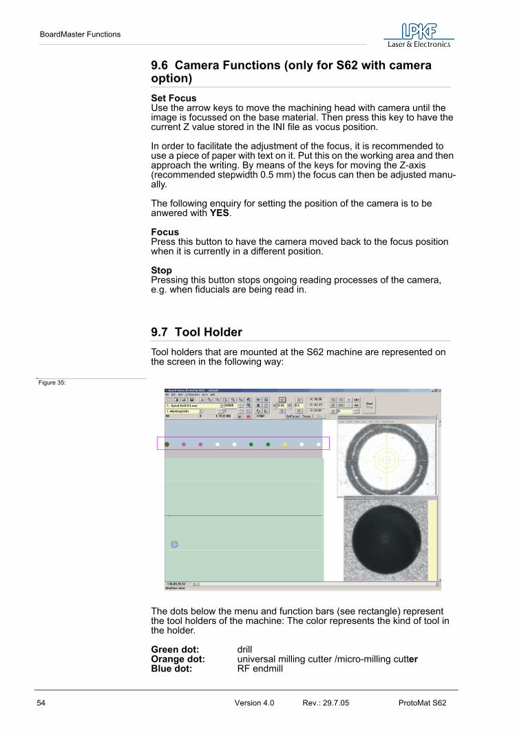
9.7 Tool HolderTool holders that are mounted at the S62 machine are represented on the screen in the following way:
Figure 35:
The dots below the menu and function bars (see rectangle) represent the tool holders of the machine: The color represents the kind of tool in the holder.
Green dot: drillOrange dot: universal milling cutter /micro-milling cutterBlue dot: RF endmill

BoardMaster Functions
ProtoMat S62 Version 4.0 Rev.: 29.7.05 55
Violet dot: end millsYellow dot: contour cutterLight green dot: Endmill long
Dot displayed with a red ring around it: Tool position reserved - tool is presently in the collet
Dot displayed in white by the software: Tool holder is free.
A detailed desciption of the tools can be found in the chapter „The tools“ on page 82.

Menu Bar
56 Version 4.0 Rev.: 29.7.05 ProtoMat S62
10.0 Menu Bar
This chapter introduces the menu functions in BoardMaster in their typical sequence of use.
10.1 Go To Menu This menu contains functions for moving the machining head to the corresponding positions:
Figure 36: Go To Menu
Danger: When an entry in the menu GO TO is selected, the connected circuit board plotter starts moving! The hazard of pinching and crushing exists!For this reason, ensure that no one can enter the motion range of the circuit board plotter during the operating phases!
HOME Select this entry to move the machining head to the HOME position (data origin).
PAUSE Select this entry to move the machining head to the PAUSE position (standard Xmax/Ymax) .
Zero Position Select this entry to move the machining head to thetool changing position (standard Xmin/Ymin).
Camera >> Head Select this entry to move the camera (if option ispresent) to the current machining head position.
Head >> CameraSelect this entry to move the machining head back to its original position.

Menu Bar
ProtoMat S62 Version 4.0 Rev.: 29.7.05 57
10.2 CONFIGURATION MenuThis menu contains all functions required for configuration of BoardMaster as well as the connected circuit board plotter:
Figure 37: Configuration menu
10.2.1 Serial Interface
An interface is preset by the manufacturer in the INI-file. If the machine is to be connected to a different interface at your computer (COM2 instead of COM1) or if you used version BoardMaster 4.0 or an older version, than BoardMaster will first start without communication build-up. The in-terface and its configuration can then be selected later in BoardMaster under „configuration -> interface“. It is important that the correct configu-ration is selected which corresponds to the connected ProtoMat machine. Otherwise the communication will not be built up correctly.
Note: When the communication has been successfully established, it is absolutely necessary to terminate BoardMaster for a short moment and then restart it so that the modified settings are written in the INI file.
Figure 38: Machine communication

Menu Bar
58 Version 4.0 Rev.: 29.7.05 ProtoMat S62
MachineAdjustable machine configurations.
H100 - 2003-:ProtoMat H100 built in 2003H100 -2004-:ProtoMat H100 built in 2004H60:ProtoMat H60S62 (Firmware 2.4.1):ProtoMat S62, with USB connectionS62 (Firmware 2.3.3)ProtoMat S62 (previous firmware version)SMCU_2AX:ProtoMat 91s, 91s/VS, 92s, C20, C30, C30s, C40, C60, C100/HF, M30/s, M60, M100, L60, X60SMCU_2AX Toolchange:ProtoMt 95s, 95s/IISMCU3AX:ProtoMat D100, M60/3DVirtual Machine:Demo-Modus for offline operationX60:ProtoMat X60/IIX60 III:ProtoMat X60 / II
InterfaceUsable communication ports of the control computer. Selectable are „RS 232“ or „USB“ (USB only for ProtoMat machines with LPKF motion.net™ controllers. A firmware update may be required)
PortHere the PC connection is selected which is connected to the machine.
Baud rate57600
LanguageIf an error occurs during operation, then BoardMaster gives necessary hints to the problem in a dialog. The language of the dialog may be set here.
Write to Comtrace.txt The dialog between the PC and the machine via the serial interface can be written in a separate file to help error detection. The file produced is called „Comtrace.txt“ and is located in the main directory of BoardMas-ter, C:\Program Files\LPKF50\Bmaster.
The following table lists all parameters of the serial interface which can be set:
Figure 39: Interface parameters
Note: the FIFO buffer must be switched on (see table above)!
The adjustment of these parameters is done in the Windows system control.
Circuit board plotter Baudrate Data bits Stop bits Parity Protocol Fifo
ProtoMat S62 57600 8 1 none Hard-ware
Yes

Menu Bar
ProtoMat S62 Version 4.0 Rev.: 29.7.05 59
Windows 2000/XP: System - Hardware - Device Manager (Login as „Admin“!!!)
If the circuit board plotter is not correctly triggered after the start of the data transfer, check the connection between PC and plotter.
Also make sure that the parameters of the serial interface in the Win-dows system control match the parameters listed in the table.
Note: The cause of incorrect communication often is an incorrectly adjusted protocol of the serial interface. Make sure that the protocol set is Hardware-Handshake and not XON/XOFF.
10.2.2 Machine Settings
Select the entry SETTINGS... in the menu CONFIGURATION to open the following dialog box:
Figure 40: Machine parameter
To prevent a change by mistake of the parameters listed in the dia-log field MACHINE PARAMETERS if you want to make a deliberate modification you have to click on the button UNLOCK to enable the editing of a parameter. The button then changes to LOCK, which must be pressed if modifications are to be stored.
UNITClick on one of the two options to have the length, diameter coordinates and so on displayed either in inch or metrically. NAMEThis text field displays the type of circuit board plotter as it appears in the BoardMaster title bar. This serves only for information purposes and has no effect on the operation.

Menu Bar
60 Version 4.0 Rev.: 29.7.05 ProtoMat S62
NUMBER OF TOOL POSITIONS The number in this text field indicates the number of tool change posi-tions. For the circuit board plotter ProtoMat S62 this is always 10.
SENDClick on this button to send the command in the entry field to the left of the button to the circuit board plotter.
For this function it is not necessary to click first on the button UNLOCK .
ROTATIONThe number in this text field indicates the maximum speed of rotation of the spindle of the circuit board plotter.
SPEED OF MOVINGThe number in this text field indicates the maximum speed of movement of the circuit board plotter when the machining head is lifted.
RESOLUTIONThe numbers in these two fields define the distance which the circuit board plotter moves in X or Y direction at one step of the stepping motor. Do not change these values under any circumstances as otherwise the correct scaling of the output cannot be guaranteed.
AutomotorIf there is a check mark the machining motor is switched before start of a production phase and it is switched off when the phase is finished.
All parameters specific to a plotter are defined in this dialog field. They are stored in an initialisation file (*.INI).
SMCU II-controlControl type SMCU II for ProtoMat S62
BoardMaster is capable to operate two types of control. Selection of the control type is preset for the circuit board plotter selected in the setup.
Note: The type of control should not be changed as otherwise the correct data transfer with the corresponding syntax is no longer possible.
Vacuum tableThere must be a check mark in this field if a vacuum table is mounted so that the correct working height is taken into account during milling or drilling. Otherwise there is the danger that e.g. during drilling of reference holes the vacuum table is damaged.
Vacuum table heightThe default value of 15 mm is set at the factory. This value should not be changed. The value is activated if the checkmark is set in the field vacuum table.
CameraIf a camera is installed, there must be a check mark in this field.
During installation, the machine parameters of your plotter are read from the initialisation disk that is supplied together with the plotter. Thus all important values like machine size and the position of the HOME posi-tion (data origin on the axis of reflection) are already programmed at the factory. The circuit board plotter is immediately ready for operation.

Menu Bar
ProtoMat S62 Version 4.0 Rev.: 29.7.05 61
All important information like HOME-position and area of travel must be sent from BoardMaster to the control of the circuit board plotter.
A chain of commands in plotter syntax can be entered in the text field START LINE. The commands are stored in the initialisation file when BoardMaster is closed and are sent to the circuit board plotter when BoardMaster is started.
All entries in the dialog field MACHINE PARAMETER are transferred to the plotter when OK is clicked to leave the program and they are stored in the initialisation file when BoardMaster is closed. Thus they are avail-able at each new start of the program.
10.2.3 Tool Parameter
The BoardMaster program provides tool libraries containing tools available from LPKF with all specific tool settings. The tool library files are available in three versions: *.TOL for drilling and milling tools, *.DIS for dispensing needles and *.VAC for evacuation needles (only with LPKF AutoContac). All lists can be changed and stored for later use.
The submenu TOOL LIBRARY in the menu CONFIGURATION provides access to the various tool libraries:
Figure 41:
Libraries:
Example:
FR4-60.tol - Processing of FR4 base materialFR3-60.tol - Processing of FR3 base materialAlu-60.tol - Processing of aluminum base materialFilm-60.tol - Processing of film foilsKapt-60.tol - Processing of solder resist or stencil foilsPlastics.tol - Processing of plastic materials
FR4-60.tol is loaded as default. Please select before starting depending on material.
› Select the entry MILL/DRILL HEAD in the menu CONFIGURATION in the submenu TOOL LIBRARY to open the following dialog box:
›

Menu Bar
62 Version 4.0 Rev.: 29.7.05 ProtoMat S62
Figure 42: Mill/Drill Tool Edit
All tools required for operation of the circuit board plotter are defined in the tool library with their characteristic properties. The individual settings are described here to allow you to change or add additional tools.
NAME This list field contains the name of the tool. The selection of the name should provide information on the type of tool to facilitate later selection in other program sections. After selecting a tool in the list field, you can display its settings and change them if required. The names selected here must coincide with those in CircuitCAM. This name allows automatic tool assignment when importing LMD files.
DIAMETERThe number in this text field indicates the diameter of the tool. This value allows automatic tool assignment when importing LMD files and the display of the actual diameter in the graphic working area.
HEAD DOWNTIMEThe number in this text field indicates the time interval in seconds between the command “Lower head” and the command “Raise head” for the drilling tool.
MILL/DRILLThe tool can be defined as a milling or drilling tool by clicking one of these two options.
DESCRIPTIONAn additional description of the tool can be entered in this text field. However, this specification has no significance for the production sequence.
LIFE CYCLEThe number in the text field MAXIMUM specifies the maximum cutting path or maximum number of holes for the tool. In the text field PRESENT; the cutting path already cut or the current number of holes for the tool is indicated.

Menu Bar
ProtoMat S62 Version 4.0 Rev.: 29.7.05 63
The tool change procedure can be started by clicking REPLACE and after replacing the old tool, the specification in the text field PRESENT is reset to 0.
OPTIMAL SPEEDThe speed in the text field ROTATION defines the optimum rpm for the machining spindle. The number in the text field MILLING defines the optimum feed rate for milling tools.
Milling infeed [mm]Value in millimeters for milling depth (engraving tools L=36mm) and infeed (cutting mills L=38mm). All milling tools that only machine the sur-face of the material or engrave it penetrate into the material with this value, after the zero position was detected by the depth sensor prior to that. Cutting mills are not detected by the depth sensor. Then the value only indicates the further infeed.
Working mode...Here parameter sets or profiles can be assigned to each tool. There are the profiles THROUGHPUT, BALANCED, QUALITY. Parameters speed, acceleration and dwell times can be stored for each of the three axes, they apply to „lower head“ (drilling) and „head down“(milling). These profiles are stored in an MCH-file and are preset for the various working mode profiles.
Note: The speed is used automatically only for circuit board plotters with variable spindle speed. For all other circuit board plotters with variable motor speed, the optimal speed must be set by hand on the control. The optimal speed to be set is, however, indicated by BoardMaster upon tool change.
All changes in the tool library can be stored in a tool file (*.TOL) and loaded again later. The file to be loaded when BoardMaster is started can be defined in the machine file “*.MCH” with the command “#INCLUDE”.This also applies for production phases, the dispenser and vacuum tools.
All changes are stored in a tool file (*.TOL) when the SAVE... button is pressed and can be loaded again later by pressing the LOAD... button.
10.2.4 Heads Dialog Box
The HEADS dialog box can be reached by clicking HEADS in the menu CONFIGURATION.
Figure 43: Heads -Mill Drill

Menu Bar
64 Version 4.0 Rev.: 29.7.05 ProtoMat S62
The various tool heads are listed in the left half and the offset associated with the specific heads are listed in the right half:
Mill/Drill head: The milling/drilling head serves as a reference for all other options mounted on the head. Its offset should therefore always be set to X = 0 and Y = 0.
Camera: The distance between a camera option mounted on the machining head and the machining head is defined here. This can be used for precise positioning for reloading circuit boards already completed.
A detailed description of how this offset is calculated is given in the following chapter.
Auto When a metal sheet is put on the table, this function is used to calibrate the camera offset automatically. This is no function in the software ver-sion for the ProtoMat S62.
10.2.5 Adjust Camera Offset
Adjust camera offset (factory setting existent)
› Select a 0.8 mm drill and drill a hole on a free area of the base mate-rial.
Caution: Do not move the machining head anymore!
› In menu CONFIGURATION open the dialog HEADS.
› Click on entry CAMERA.
Figure 44: Heads
› Press button ORIGIN. The button then turns to gray.
› Quit this dialog by clicking on OK.
› In the menu GO TO click on CAMERA>>HEAD

Menu Bar
ProtoMat S62 Version 4.0 Rev.: 29.7.05 65
› Now move the head as long as the cross wires of the camera image are exactly in the center of the hole. For better positioning decrease the step width to 0.005 mm.
Figure 45: Camera
› Open the HEAD dialog box again.
› Press the button HEAD to accept this new position. Then the coordinates in the field OFFSET should change.
› Quit this dialog with OK.
10.2.6 Phase... - Production Phases
All data to be transferred to the circuit board plotter by BoardMaster must be assigned to a certain production phase. These production phases define a work sequence which does not require any manipulations by the user. An example of such a manipulation would be through contacting the circuit board or turning the base material. The only exception here is manual tool change. This assignment is prepared in CircuitCAM and is accomplished automatically in BoardMaster.
Some production phases are already defined in the initialization file. However, you can adapt these production phases to your specific requirements at any time. The names of the production phases must coincide in CircuitCAM and BoardMaster.
› Select the entry PHASES... in the menu CONFIGURATION to open the following dialog box:

Menu Bar
66 Version 4.0 Rev.: 29.7.05 ProtoMat S62
Figure 46: Phases
All standard defined production phases are listed in the list field. After selecting a production phase, you can view its settings and change them if required.
Two settings are required for each production phase:
• The color with which the data assigned to this production phase is to be displayed. This setting serves for differentiation of the various production phases on the working area.
• Definition of the circuit board side (visible = component side or reversed = soldering side) for the production phase. Mark the indicator box REVERSE SIDE for all production phases for processing the bottom of the circuit board. All other production phases for which the indicator box REVERSE SIDE is not marked, are defined for processing the top.
To create a new production phase:› Mark the production phase in the list field in front of or in back of the
new production phase you want to add.
› Enter the name of the production phase in the text field.
› Click INS ABOVE or INS BELOW to insert the production phase at the corresponding point in the list field.
Press the SAVE button to store all changes in the PHASES... dialog box in a phase definition file (*.PHS) so that it can be loaded again later by pressing the LOAD button.
Note: On one-sided material, the option “REVERSE SIDE” should be activated for the phase “CUTTING OUTSIDE“! This eliminates the necessity of turning the base material.
Meaning of the phase files
1-2layer.phsProduction of single and double-sided boards4layer.phsProduction of 4 layer multilayer boards (sequential build-up method)6layerpin.phsProdution of 6 layer multilayer boards (registration pin method)soldermask.phs

Menu Bar
ProtoMat S62 Version 4.0 Rev.: 29.7.05 67
Cutting of solder foil „system EasySolder“
10.2.7 Defining the Base Material Size
When preparing a new job, it is first necessary to define the size of the base material used. This is necessary to display the actual processing surface available in the working area and therefore allow optimum positioning of the circuit board data.
The material size can be defined in the menu CONFIGURATION in the submenu MATERIAL:
Figure 47: Material Size
This submenu offers two possibilities for defining the material size:
• Determination of size by moving circuit board plotter and reading in coordinates.
• Manual entry in the SIZE dialog box.
Determining the size by moving the machining head:
Precise determination of the base material size can be accomplished with the circuit board plotter connected with the functions SET X,Y-MIN and SET X,Y-MAX in the submenu MATERIAL in the menu CONFIGURATION.
When defining the material size, observe attachment strips and the size of the working depth limitation as well as the position of the reference hole pins.
When a new job is defined; the already defined material size is deleted.
Danger! The following instructions should be read before starting the circuit board plotter as it sets the plotter in motion!
Ensure that no one can enter the motion range of the circuit board plotter. Danger of pinching and crushing!
Also observe the safety precautions for the circuit board plotter!
› Move the machining head of the circuit board plotter with the arrow
keys to the “front right corner” (X/Y-Min) on the circuit board material.
› Select the entry SET X, Y-MIN in the submenu MATERIAL in the menu CONFIGURATION.
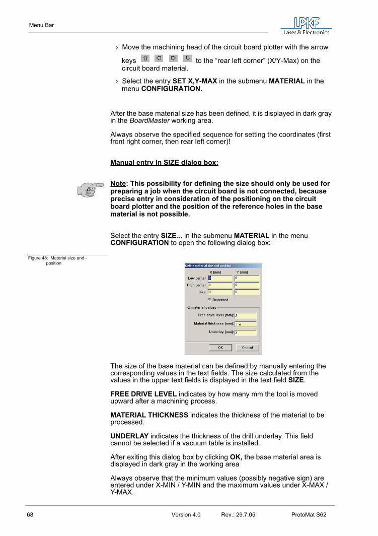
Menu Bar
68 Version 4.0 Rev.: 29.7.05 ProtoMat S62
› Move the machining head of the circuit board plotter with the arrow
keys to the “rear left corner” (X/Y-Max) on the circuit board material.
› Select the entry SET X,Y-MAX in the submenu MATERIAL in the menu CONFIGURATION.
After the base material size has been defined, it is displayed in dark gray in the BoardMaster working area.
Always observe the specified sequence for setting the coordinates (first front right corner, then rear left corner)!
Manual entry in SIZE dialog box:
Note: This possibility for defining the size should only be used for preparing a job when the circuit board is not connected, because precise entry in consideration of the positioning on the circuit board plotter and the position of the reference holes in the base material is not possible.
Select the entry SIZE... in the submenu MATERIAL in the menu CONFIGURATION to open the following dialog box:
Figure 48: Material size and -position
The size of the base material can be defined by manually entering the corresponding values in the text fields. The size calculated from the values in the upper text fields is displayed in the text field SIZE.
FREE DRIVE LEVEL indicates by how many mm the tool is moved upward after a machining process.
MATERIAL THICKNESS indicates the thickness of the material to be processed.
UNDERLAY indicates the thickness of the drill underlay. This field cannot be selected if a vacuum table is installed.
After exiting this dialog box by clicking OK, the base material area is displayed in dark gray in the working area
Always observe that the minimum values (possibly negative sign) are entered under X-MIN / Y-MIN and the maximum values under X-MAX / Y-MAX.

Menu Bar
ProtoMat S62 Version 4.0 Rev.: 29.7.05 69
10.3 File Menu
The functions in this menu serve for handling jobs and projects in BoardMaster:
Figure 49: File Menu
NEW Select this entry to create a new job in BoardMaster.
OPENSelect this entry to open a job already present inBoardMaster. Version 3.x job files can also be loaded.However, it is necessary to reassign the tools, because the tool names are not identical and BoardMaster cannot find the old names.(See "Introduction to the Basic Functions of the ProtoMat S62" on page 38)
SAVESelect this entry to store the job opened in BoardMasterunder the file name indicated on the BoardMaster title bar.
SAVE AS...Select this entry to store the job opened in BoardMaster
under a new file name.
IMPORTThis submenu contains functions for importing productiondata or projects into BoardMaster:
LMD OR LPR...Select this entry to import LMD files (CircuitCAMproduction data) or LPR files (BoardMaster HP-GL projects)into BoardMaster. Version 3.x LMD files can also be imported. However, it is necessary to reassign the tools(„Assigning Tools“ on page 70 and the production phases,because these names are not identical and BoardMastercannot find the old names.
NC-ConvertWithout function
HP-GL INTOIn this submenu, select the entry

Menu Bar
70 Version 4.0 Rev.: 29.7.05 ProtoMat S62
NEW LPR..., to import the HP-GL files into BoardMaster and assign them
to a new project.
<STANDARD>, To import the HP-GL files intoBoardMaster and assign themto the Standard project.
After importing LMD files, data is positioned immediately in the middle of the working area for the circuit board plotter. Moreover, the production data and the required tools are automatically assigned to the data: If it is not possible for BoardMaster to assign one or more tools, the following message appears:
Figure 50: Import
In this case, it is necessary to assign the tools manually in the tool assignment dialog box or to complete the tool library before importing the data again.
After exporting the files, all tools required are listed in the CircuitCAM report window.
10.4 Edit Menu Figure 51: Edit Menu
10.4.1 Assigning Tools
Each job in BoardMaster consists of one or more projects. Here, a project is designated to be a circuit board imported as LMD file or HP-GL project.
Select the entry TOOL ASSIGNMENT in the EDIT menu to open the following dialog box:

Menu Bar
ProtoMat S62 Version 4.0 Rev.: 29.7.05 71
Figure 52: Edit tool assignment
Generally, the production data is read in by importing it in the file menu. These projects can, however, also be inserted at this point (LMD file from CircuitCAM) or generated (HP-GL files).
The LMD files generated during export in CircuitCAM contain the production data for the entire circuit board. The LMD files imported into BoardMaster are listed in the project list. The CircuitCAM layers with their production phases (phase) are listed in the field Phase file/Layer. Each of these entries contains one or more pieces of tool information (pins) with the assigned tools from the BoardMaster tool library (tool).
If automatic tool assignment was not possible (see above), it is necessary to perform it here:
› Select the Layer from the list, for which this assignment is missing.
› Open the Pen list field and check whether a tool is assigned to each “pin”.
› If not, select the tool to be used here from the Tool list field.
Repeat this until all tools have been assigned correctly.
To create a new project:
Such a project (LPR) consists of one or more HPGL files.
› Click CREATE PROJECT... to create a new project.
› Assign a name for the project in the dialog field ENTER NEW LPR NAME:

Menu Bar
72 Version 4.0 Rev.: 29.7.05 ProtoMat S62
Figure 53: Enter new LPR name
› Click OK to close the dialog box.
› Enter the resolution for the HP-GL files associated with the project in the text field UNIT.
The HP-GL files have a standard resolution of 0.025 mm. If you want to use data with a different resolution, please change the setting for the HP-GL unit:
› Click ADD to add the desired HP-GL files to the project.
Note: All HP-GL files for a project must be located in the same directory.
You can remove HP-GL files from a project by marking the corresponding entry in the list field PHASE FILE/LAYER and clicking REMOVE.
It is necessary to assign the following information to each HPGL file with production data in FILE/LAYER:
PHASE In this list field, select the phase to be assigned to the production data.
PIN/TOOL Select the pin for the HP-GL file in the LIST field pinto which the tool selected in the list field TOOLis to be assigned.
Y=>-Y Activate this control box to allow simultaneous,coincidental display of both sides of the circuitboard for production data generated as a mirrorimage (generally, the bottom for all production data).
› Click SAVE AS to store the project as an LPR file.
In order to reopen a project stored as LPR file, after restarting the BoardMaster program, select the entry LMD OR LPR... in the submenu IMPORT in the FILE menu.
or:
Click ADD PROJECT to add a project. This can be an LMD file generated with CircuitCAM or an LMD file (HP-GL project file) generated with BoardMaster.

Menu Bar
ProtoMat S62 Version 4.0 Rev.: 29.7.05 73
10.4.2 Placing Projects
After you have imported or generated the required projects, you can place them in the BoardMaster working area. Imported projects are automatically positioned in the center of the working area or the predefined base material.
Select the entry PLACEMENT... in the EDIT menu to open the following dialog box:
Figure 54: Placement
To place a project: › Click Add... and select a project from the list. Or:
Select the project whose positioning you want to change on the left side in the list field.
› Enter the desired scale for the project in the text field SCALE.
The default value for the scale is 1, indicating scale 1:1.However, you can also define another scale here, for application such as front plate and plate engraving.
› Enter the desired position for the project in the working area in the text field X and Y under ORIGIN. These values refer to the HOME position for the circuit board plotter and the data origin.
If you do not know the exact position of the data in the coordinate system, you can enter the value 0 and 0 here and position the project in the working area with the aid of the function bar/mouse.
› Select the appropriate offset for the project in the working area under ROTATION.
› If you want to complete more than one prototype for a project, define the number of multiple boards under COUNT. Enter the number of boards in the X direction in the first text field and the number of boards in the Y direction in the second text field.
› Enter the interval of the boards under DISPLACEMENT. Enter the displacement of the boards in the X direction in the first text field and the displacement of the boards in the Y direction in the second text field.

Menu Bar
74 Version 4.0 Rev.: 29.7.05 ProtoMat S62
The displacement of the boards in relation to one another must correspond to at least the length and width of the circuit boards, because otherwise, the boards would overlap.
Multiple boards can also be created with the function bar.
Centering a project on the base material:
› Select the corresponding project in the list field.
› Click CENTER to position the selected project in the center of the base material.
To add other projects for placement:
› Click ADD.
› Select the project to also be positioned on the base material in the list field:
Figure 55: Select Project
› Click OK to close the dialog box.
To remove a project already positioned:
› Select the corresponding project in the list field.
› Click Delete to remove the positioned project from the base material.

Menu Bar
ProtoMat S62 Version 4.0 Rev.: 29.7.05 75
10.4.3 Select Tools
The SELECT dialog window can be used to disable individual tools for processing in the current production phase.
The dialog window shows all of the tools used in the current production phase. Normally all tools in the list are marked (dark background), i.e. enabled for use.
Clicking one of the tools allows it to be disabled (light background) or enabled (dark background). Disabled tools are not used for processing during the production phase, even though they are included in the project.
Figure 56: Select Tools
Example: A dull drill is detected while drilling. By selecting only this tool, pressing ALL+ and START, only the holes with this tool are repeated, all others are ignored.
Moreover it is possible to define in this list field, whether the smallest tool is to be used first (recommended for milling insulation), followed by the next thicker tool, or if the current tool is to be used first (for drilling, to avoid unnecessary tool changes).
A detailed description of the tools can be found in the chapter „The tools“ on page 82.
10.5 Reload Dialog Box The function RELOAD serves for reloading a circuit board which has already been completed and cut, in order to drill additional holes, engrave text or separate the conductors for coding.
The prerequisites for using the reload function include a circuit board requiring reprocessing and the circuit board data as LMD file with at least two identifiable points (holes, reference marks, vectors), which can be assigned to the corresponding points on the circuit board.
The main purpose of the reload feature is to position the data so that it coincides with the circuit board to be processed. For this purpose, two identifiable points in the data (reference points) are assigned to the corresponding points on the circuit board to be processed.

Menu Bar
76 Version 4.0 Rev.: 29.7.05 ProtoMat S62
When RELOAD is selected, the floating dialog box RELOAD MATERIAL is opened.
Figure 57: Reload Material
To reload, the following steps are required:
Danger: Activating one of the following buttons on the function bar, sets the connected circuit board plotter in motion! The danger of pinching and crushing exists!Ensure that no one can enter the hazard area of the circuit board plotter during the operating phases controlled by BoardMaster or come into contact with the tools!
Work sequence:
› Fasten the circuit board to be reloaded on the plotter.
› Import the LMD file with the corresponding data for the circuit board.
› If not already accomplished, open the RELOAD MATERIAL dialog box. Switch on the switch for Point 1 and select the first reference point on the data (center point of solder eye or hole, corner point).
› Move the mark to the desired position by clicking the keys
CENTER or CORNER.
- Hole selection only
- Pad selection only
› Move the machining head with tool installed or the cross hairs on the camera (LPKF CircuitView Option) as exactly as possible to the appropriate point on the circuit board. For this purpose, use the motion keys on the function strip:
› Then click the Read button to store this point.

Menu Bar
ProtoMat S62 Version 4.0 Rev.: 29.7.05 77
› Switch on the switch for Point 2 and repeat the procedure for the 2nd reference point.
› Mark the check box Enable.
› Exit the dialog box by clicking OK to activate “Reload“.
› Select the data to be sent to the plotter. The data is converted to correspond to the position of the circuit board after clicking Start.
Then cancel the mark in the ENABLE check box to prevent the data from being aligned for later jobs. Exit with OK and close the floating dialog box.
10.6 View MenuYou can adapt the graphic display of the BoardMaster working area to your specific requirements with the functions in the View menu:
Figure 58: View menu
ZOOM AREA Select this function to display a freely selectablecutout of the working area to fill the screen.For this purpose, press the left-mouse key andhold down while moving the mouse to definethe desired area. You can also select this
function by clicking on the function bar.
ZOOMING 1.5x Select this function to increase the graphicdisplay by a factor of 1.5.
ZOOM OUT 1.5x Select this function to decrease the graphicdisplay by a factor of 1.5.
MACHINE Select this function to display the entire workingsurface of the circuit board plotter in the working area.
MATERIAL Select this function to display the entire basematerial surface in the working area.
ALL PROJECTS Select this function to display all positioned projects as largest possible in the working area.
PREVIOUS Select this function to return to the previousscreen display.

Menu Bar
78 Version 4.0 Rev.: 29.7.05 ProtoMat S62
BOTH SIDES Select this function to change back and forth between simultaneous display of both sides ofthe circuit board and display of only one side ofthe circuit board.
REAL TOOLS Select this function switch display of the milledlines in the actual width ON and OFF. The actualwidth of the milled lines is defined in the toollibrary.
DEFAULT FONT Select this function to change back and forthbetween the Windows system font and the fontset under CHANGE FONT for display of the text.
CHANGE FONT... Select this function to select the font to be displayed when the DEFAULT FONT isdeactivated.
10.7 Selecting Production PhaseBefore sending milling or drilling data to the circuit board plotter, it is first necessary to select the production phase to be processed. This can be selected on the function bar in the list field PRODUCTION PHASE:
Figure 59: Production Phase
Select the production phase to be processed next. Ensure that only one production phase is marked to which an HP-GL file or LMD file has also been assigned. Erroneous selection leads either to erroneous files being processed or no data being transmitted at all.
An example for the sequence for the production phases for a double- sided circuit board is given below:
Process Production phase
Configuring tools for tool change MarkingDrills
1. Drilling DrillingPlated
2. Milling bottom MillingBottom
Turning base material
3. Milling top MillingTop
4. Cutting outside CuttingOutside

Menu Bar
ProtoMat S62 Version 4.0 Rev.: 29.7.05 79
10.8 Automatic Tool Change The dialog box shown in figure 60 on page 79 can only be called up when machines with automatic tool changing unit are used. (example ProtoMat 95s, H100 and so on). If you now open the TOOL list field on the function bar, only the thirty or seven tool positions with their corresponding tool assignment are displayed instead of a list of all tools as for circuit board plotters with manual tool change.
Figure 60: Automatic tool change
Note: When the program is started for the first time, the tool <UNKNOWN> is assigned to each tool position, i.e. no tool entered. This is intended to cause the user to check the tools in the circuit board plotter magazines and assign the corresponding positions in the TOOL POSITIONS dialog box. It is absolutely necessary to ensure that the tools in the tool box coincide exactly with those assigned in BoardMaster in order to prevent using the wrong tools and therefore malfunctions. Open the TOOL POSITIONS dialog box by clicking the TOOL list field with the right-mouse key:
A tool can be assigned to the tool positions 1 to 10 by selecting the tool required for the production phase from the appropriate list field.
If a tool position is not assigned to a required tool, this dialog box is opened automatically when the production phase is started. It is possible to continue only after all tools have been assigned a position!
The tools required for the selected production phase are listed in the list field WANTED FOR CURRENT JOB (PHASE).
The option SELECT indicates the tool momentarily located in the machining head.

Menu Bar
80 Version 4.0 Rev.: 29.7.05 ProtoMat S62
The CURRENT life cycle and the MAXIMUM life cycle are indicated following each tool.
It is necessary for the New check box to be switched on when a used tool is replaced by a new tool in the tool box. The current life cycle is then reset to 0.
When exiting BoardMaster, the tool assignment in BoardMaster are stored under the name extension *.TLS and automatically reloaded each time BoardMaster is started.

Operating Procedures
ProtoMat S62 Version 4.0 Rev.: 29.7.05 81
11.0 Operating Procedures
This chapter explains all common operating procedures with the circuit board plotter as well as the tools and their application possibilities. Special applications are also explained, which are not necessarily important immediately for “beginners” and therefore may be confusing at the beginning. As “beginners”, you should, however, always work your way through the following subchapters:
• Fastening the base material
• Drilling
• Insulation milling
• Contour milling in circuit board material
• Cleaning the circuit board
The remaining subchapters in this chapter can be read later if required when you are familiar with the circuit board plotter.
11.1 Fastening the Base Material
When the machine is started up for the first time, you will note that a double-sided piece of base material is already present on the machine base plate. Moreover, a reference hole system is preset at the factory. If you have to process different sizes of base material, it will be necessary for you to first create a new reference hole system if this is not already existent. This procedure is described in detail in the BoardMaster chapter.
The primary preparations are explained in keywords here. If you are working with a LPKF circuit board plotter for the first time, perform this work only after you have worked through the BoardMaster chapter. You will be referred to it at the corresponding point in the manual!
› Drill coincidental reference holes in the base material and drilling plate in the X direction (diameter 3 mm). This can also be accomplished with any desired drill press. Note that the diameter is reduced by galvanic throughplating.
› Move the machining head to the PAUSE position. Insert reference hole pins into the reference hole strips on the left and on the right.
› Position the base material on the reference hole pins.

Operating Procedures
82 Version 4.0 Rev.: 29.7.05 ProtoMat S62
Figure 61: Fixing the board
The reference hole pins hold the circuit board in position. This is particularly necessary during contour milling. On the other hand, they are also used as a reference when turning double-sided circuit boards.
Danger! Switch on the vacuum before milling/drilling! Remember to replace the vacuum filter as required! Inhaling the material dust poses a health hazard!
Note: It is important that no contamination (adhesive tape residues, drilling or milling chips) is present between the individual layers so that the base material lays perfectly flat. Small particles below the base material would have a negative effect on the uniformity of the milling depths.
11.2 The toolsAll tools are fitted with spacer rings to ensure the precise pick up and set down of tools. The different tools are marked by different colours:
In addition the diameter is indicated on the spacer rings, e.g. 1 for 1 mm, and .1 for 0.1 mm diameter.
Figure 62: Tools with ring and color code
1- Machine bed (aluminum base plate)2- Reference hole pins, 3 mm diameter 3- Base material approx. 1.6 mm thick 4- Drill underlay material
1- Spacer ring with color code
Tool type Color Diameter (in mm)Drills green 0.2-2.4 ; in 0.1 stepsUniversal milling cutter/Micro--milling cutter
orange 0.1 and 0.25
RF-Endmill cutter blue 0.1; 0.15; 0.25; 0.4 End mills violet 0.8; 1.0; 2.0; 3.0Contour cutter yellow 1.0; 2.0; 3.0Endmill long light green 1.0; 2.0
1

Operating Procedures
ProtoMat S62 Version 4.0 Rev.: 29.7.05 83
11.3 Drilling
In addition to milling, drilling is one of the primary purposes of the circuit board plotter. Circuit boards are drilled with special circuit board drills.
It is only possible to drill one circuit board at a time. Never attempt to drill a number of circuit boards on top of one another! A drilling cover plate is not required. All drills have a length of 38 mm. Further instructions are contained in the Chapter „Practical Tips“ on page 87.
Caution! Before drilling, ensure that the base material is seated tightly! Switch on the vacuum!
11.4 Insulation Milling
Insulation milling is the designation for cutting milled tracks around the later conductors. This insulates the conductors from the remaining copper coating. Various types of tools are available for the different materials and applications (see figure 8 on page 21). Each of these tools produces different milling tracks (see figure 64 on page 84).
Figure 63: LPKF Unversal cutter, micro cutter and RF cutter
Universal milling cutter
Before milling, it is necessary to ensure that only sharp LPKF universal milling cutters (36 mm long) are used. The milling width can be adjusted between 0.2 and 0.5 mm according to the thickness of the tool by changing the milling depth.
Note: It is advisable to degrease the base material with a cleaning spray before processing (degreaser for electronic components). This allows the drilling chips to be vacuumed up more easily.
In principle, the milling width should not be smaller than 0.2 mm. If work is accomplished only with the front-most tip of the milling cutter, the tool wears more quickly than at greater milling depths.
1- Universal milling cutter2- Micro milling cutter3- RF milling cutter
1
2
3

Operating Procedures
84 Version 4.0 Rev.: 29.7.05 ProtoMat S62
Micro milling cutter
Finer insulation channels can be produced with the LPKF micro milling cutters, however, the service life of these cutters is approx. 10% of that of the LPKF universal milling cutters mentioned above.
Caution! Do not mix up micro milling cutters and universal milling cutters! The two can only be differentiated under a microscope.
RF milling cutter
A special cutter which produces a rectangular insulation channel in one cut has been developed specially for RF technology.
Figure 64: Milling track by LPKF Universal cutter, Micro cutter and RF cutter
Further information is given in the Chapter „Practical Tips“ on page 87.
After processing, it is necessary to clean the circuit boards. This can be accomplished with a brush machine or manually with board cleaners (LPKF accessory). In all cases, it is necessary to rinse the circuit boards thoroughly with water to rinse off any copper dust resulting from brushing.
After rinsing, it is necessary to dry the circuit board well (hot air gun) and then protect it against oxidation with soldering varnish.
Caution! Before milling, ensure that the base material is seated tightly! Switch on the vacuum!
11.5 Contour Milling in Circuit Board Material
The contour milling cutters should always be used for cutting out the circuit board after it is completely machined or for drilling holes with a diameter greater than 2.4 mm when the circuit board is to be cut through in the entire material thickness.
1- Milling track, universal milling cutter
2-Milling track micro milling
cutter
3-Milling track RF milling cutter
1 2 3

Operating Procedures
ProtoMat S62 Version 4.0 Rev.: 29.7.05 85
Figure 65: Contour cutter (1) end mill (2)
The motion rate should be reduced for contour milling. The speed varies from material to material. Use only special contour cutters (38 mm long) with a diameter of 1 or 2 mm if possible.
The 1 mm contour cutter should be used for internal cutouts (small inner radius). Due to the lower stability, the feed rate should be reduced to a minimum.
The 2 mm milling cutters are considerably more sturdy, however, remove less material than the 3 mm contour cutters.
So-called “End mill” cutters are used for contour milling on soft RF base materials instead of contour cutters.
Caution! All speeds and feed rates specified in BoardMaster refer to FR4 material. Other materials (in the form of libraries) can be selected in the menu CONFIGURATION/TOOL LIBRARY / MILL/DRILL ... /LOAD. Lower feed rates should be used initially for all other materials.
Danger! Remember that carcinogenic dust (from fiber glass) can occur when machining material such as FR4. Therefore, always work with vacuum switched on. Always use microfilter.
Danger! Vitally hazard gases can occur when machining some materials !
11.6 Milling Wide Insulation Channels
Figure 66: End mill
Wide insulation channels can be cut with a 36 mm long two-tip cutter (End mill). Various diameters are available.
The 3 mm two-top cutter is particularly suited for milling very wide insulation channels (VDE specifications).
1- Contour cutter2-End mill
1
2

Operating Procedures
86 Version 4.0 Rev.: 29.7.05 ProtoMat S62
11.7 Cleaning Circuit Boards Before installing the equipment, it is necessary to carefully clean the completely milled circuit boards. This can be accomplished with a circuit board brushing machine or by hand.
To clean by hand, place the circuit board on a level surface. Brush the circuit board in the primary direction of the conductors with a wet circuit board cleaner (e.g. LPKF board cleaner PAD). Brushing is required to remove the oxidation layer and also remove chips in the insulation channel. After brushing, the circuit board should be metallically bright. From now on, the circuit board should only be touched at the edges with gloves. Then rinse off the circuit board preferably under hot flowing water to remove any brushing chips from the insulation channels and then dry with a hot air gun.
Caution! Never blow off with compressed air, because the oil particles contained in the compressed air can cause problems during further processing.
After drying, spray the circuit board with solder varnish on both sides.

Practical Tips
ProtoMat S62 Version 4.0 Rev.: 29.7.05 87
12.0 Practical Tips
This chapter contains tips gained from practical experience on various aspects of circuit board production with your circuit board plotter. We recommend reading these tips before operating the circuit board plotter to familiarize yourself with a few possible sources of error and exclude them.
Milling depth: Adjust the milling depth so that engraving is too deep rather than too shallow. If the engraving is too shallow, the milling tool wear more quickly.
Evacuation of the milling and drilling chips with the vacuum attachment is also important for precise milling depth.
Milling depth irregular:
Is the machine bed really clean? Adhesive tape residues or similar can have a high effect on the milling depth. Milling chips between the machine bed, drilling plate and base material can also reduce the accuracy.
Deformed based material:
Bend highly deformed material so that the sag points downward; then fasten the edges well with adhesive tape.
Loops between milling tracks:
Loops between the milling tracks can occur from incorrect milling sequence, particularly with circles. When a circle is milled counterclockwise with a tool which rotates clockwise, overlapping milling tracks can lead to fine loops between the copper sur-faces. The cause is a reduction of the cutting speed at the outer edges. The solution here is to define the correct milling sequence in LPKF CircuitCAM. The LPKF CircuitCAM standard processing already contains the correct milling directions (see LPKF CircuitCAM Manual).
Milling burr: A milling burr can be caused by dull tools or incorrect feed rate. If the structure to be milled allows, this can be corrected by setting deeper. Otherwise, replace tool.
Burr during contour milling:
Burrs during contour milling or unclean cut edges result either from a dull tool or incorrect feed rate.
Color of milled channel:
The color of the milled channel provides information on the condition of the tool with some materials. With epoxy materials, dark insulation tracks indicate that the tool is sharp, light tracks that the tool is dull.
Drill burrs: Drill burrs occur with dull tools: In this case, replace the tool (drill). Another possible cause can be too high speed during lowering of the machining head.

Practical Tips
88 Version 4.0 Rev.: 29.7.05 ProtoMat S62
Deviation of drill: Deviation of the drill occurs particularly with thin tools which are no longer fully sharp. However, it also depends on the surface structure of the material. For example, when the fiber glass structure on FR4 materials is pressed through by the copper, deviation of the drill is unavoidable even with a sharp tool. On materials with additional, removable copper foil (FR4 material with 9 µm or 5 µm Cu coating), deviation of the drill is very low. The holes can be center-punched first in an additional step. This also prevents deviation of the drill.
Glazing of hole: The hole tends to become glazed by the base material melting when the drill remains in the hole too long after drilling through. These holes then present problems for through-contacting. If necessary, reduce drilling times.
Drills break: Drills tend to break when the drilling plate has already been used numerous times. The drilling plate should be changed with each new circuit board: If a drill hits against the edge of a hole already present in the base plate, breakage can hardly be avoided. Always remove broken tools from circuit boards and drilling plates.
Uneven milling channels:
Milling channels when milling foil become uneven when air is present below the film. If the film is fastened with stretchable adhesive tape, the film can become wavy after a time. Particularly important here is the evenness of the milling base (LPKF engraving foil base).
Burr with foil milling:
Burrs during foil milling occur either as a result of a dull tool or milling too deeply.
Offsets between top and bottom sides:
Offset between the top and bottom side occurs when the HOME position has not been programmed precisely, the reference hole pins are positioned at an angle or loose.

Other BoardMaster Functions
ProtoMat S62 Version 4.0 Rev.: 29.7.05 89
13.0 Other BoardMaster Functions
13.1 Learning Fiducial (Option)Here the image processing software for the recognition of fiducials is cal-ibrated. Fiducials are learnt and the scale is adapted. For the H100 cir-cles or drill holes, respectively, can be used as fiducials. Considering the available camera image area, drill holes with a diameter of 1.5mm are especially favourable.
For the calibration proceed as follows:
› Choose a 1.5 mm drill and drill a hole on the free area on the basis material.
› Move the camera directly over the hole (see following image). To do this, use function "Camera >> Head“ from the menu "Move to".
Figure 67: Drill hole in camera field
› Open the dialog FIDUCIALS from menu CONFIGURATION.

Other BoardMaster Functions
90 Version 4.0 Rev.: 29.7.05 ProtoMat S62
Figure 68: Settings fiducial recognition
Explanation of the settings:
IMMEDIATELY RECOGNIZED IF HIGHER THANThe fiducial is considered as immediately recognized if the percentage recognition is higher than the entered value. In this case it is not tried to get an improved result. If the value is smaller, the detected center of the fiducial is moved to the center of the camera image to perform a further recognition.
TRY ON NEXT SPIRAL POSITION IF LOWER THAN When the recognition is lower than the entered value, the next position in the search area is moved to. The search area is traversed starting from the middle in a square-shaped and helical way. The distance between the search positions is selected such that the whole search area is covered.
MOVE TO CENTER IF IMPROVEMENT IS HIGHER THANThis parameter is connected to „Immediately recognized if higher than“. If an improvement higher than the entered value is achieved by moving the fiducial to the center of the image, then another displacement is performed. At each recognition the center of the fiducial is determined again, and used when another displacement takes place. This displacement and recognition is continued until the improvement is lower than the entered value, or the value for „Immediately recognized if higher than“ is reached.
SPIRAL SEARCH AREA SIZEThis defines the area in which a fiducial is searched for. This area is checked in a helical way, starting from the center of the fiducial in the LMD data. The area should not be defined larger than 2 mm as the search process may then take a very long time.

Other BoardMaster Functions
ProtoMat S62 Version 4.0 Rev.: 29.7.05 91
SHOW FIDUCIAL FORThis determines for how many seconds each fiducial is shown in the camera image after a successful recognition before the next fiducial to be searched for is moved to.
MAX. STRETCH THRESHOLDDuring fiducial recognition the distances between the recognized fiducials are detected. If the difference of the detected fiducials and the fiducials of the LMD data is too big, then the alignment will not take place. A corresponding error message is displayed. The entered value determines the maximum percentage difference.
REQUIRED NO. OF FIDUCIALSHere is determined how many fiducials must be recognized so that the alignment can be performed. If the number of recognized fiducials is lower, then an error message is displayed. If the number of required fiducials is set to 3, but 4 fiducials are present in the data and 4 fiducials have also been recognized, then the alignment after 4 fiducials is used.
TRAINED FIDUCIALThe list field shows the stored fiducials. If an entry is selected from the list, the corresponding image is displayed in the window Trained fiducial. The image loaded when dialog box FIDUCIAL RECOGNITION is opened, is again displayed when the dialog box is closed by clicking on OK or ESCAPE.
LOADClick on the button LOAD and the image of the fiducial selected in the list and displayed in the window TRAINED FIDUCIAL is taken over when the dialog box is closed with OK . When the dialog box is closed with ESCAPE the image loaded when the dialog box FIDUCIAL RECOGNITION is opened will again be displayed.
DEFAULTA click on the button DEFAULT sets all settings back to the original values. Thus all values are set as after the start of the program.
› To start, press the button CALIBRATE in the static field.If the calibration was successful, then BoardMaster displays the following message.
Figure 69: Fiducial recognition
› Confirm the message by clicking on OK.
There may be several reasons if the calibration was not successful, which can be recognized through the corresponding BoardMaster mes-sage:

Other BoardMaster Functions
92 Version 4.0 Rev.: 29.7.05 ProtoMat S62
The representation of the hole to be measured should be as shown in the following figure.
Figure 70:
Here fiducial recognition is finished.
13.1.1 Adjusting Milling Depth
To adjust the milling depth:› To adjust the milling depth, select a milling cutter from the tool list
field. The tool change will be done automatically.
› Move the machining head with the aid of the arrow keys and increment adjustment to a free point on the base material where you can make a cut for checking.
› Set the motion increment to 10 mm.
Error Correction
Brightness or image con-trast too low!
Adjust setting at the objective and adjust brightness.
Hole not round or too much burr.
Drill again with new tool.
Speed for lowering head is too high. Decrease the speed for lowering by adjusting the throttle valve.
After the gal-vanic process the copper surface is very shining, fiduci-als are not recognized.
Roughen the surface of the board in the area of the fiducial holes by means of emery paper or similar material.

Other BoardMaster Functions
ProtoMat S62 Version 4.0 Rev.: 29.7.05 93
› Switch on the vacuum system!
› Switch on the motor by clicking .
› Click the raise/lower button to lower the machining head.
› Move the machining head with the arrow keys.
› Click the raise/lower button again to lift the machining head.
› Switch off the motor by clicking .
› Switch off the vacuum system
› Move the machining head far enough away from the sample cut and check the depth of the cutting line with the aid of the measuring magnifier.
If the desired depth was not reached, adjust the milling cutter higher or lower with the knurled knob and repeat this operation until the desired depth or height is reached.
Manual adjustment of the miling depth
The milling depth can be adjusted by turning the knurled nut on the working depth limiter. When the wheel is turned clockwise, the mill-ing depth is increased, turning counterclockwise reduces the mill-ing depth.
• Turning the knurled nut by one increment changes the milling depth by approx. 4 µm.
• Turning the knurled nut one complete rotation changes the milling depth by approx. 0.5 mm.
13.1.2 Drilling Reference Holes in Base Material
This is required if you want to use a new piece or difference piece of base material. The values specified here apply for the base material size present when the machine was delivered (9“ x 12“). For other base material sizes, it is necessary to set other increments and where applica-ble, drill new reference holes in the reference strip. To drill reference holes, it is necessary to ensure that the circuit board plotter is ready for operation and BoardMaster is opened. Then proceed as follows
› Move the machining head to the PAUSE position by clicking the menu Go to... - Pause position
› Carefully remove the reference pins with a pair of flat-nosed pliers. Ensure that the red reference hole strips do not slip and are not pulled out.

Other BoardMaster Functions
94 Version 4.0 Rev.: 29.7.05 ProtoMat S62
› Position the drill template and base material on top of one another centered on the machine board and fasten it on the longitudinal sides with masking tape (we recommend Tesakrepp 5250).
› Then select Spiral Drill 3.0 mm in the tool list field in BoardMaster.The mache changes the tool.
› Move to the HOME position (menu bar Go to...- Home position)
› Move the machining head with the aid of the arrow keys and increment adjustment across the base material in the negative X direction (not in Y direction under any circumstances), until an interval of approx. 5 mm is present between the front edge of the base material and drill .
› Move the machining head 295 mm in the X direction (for this purpose, set increment to 295) and check visually whether a distance of approx. 5 mm is also present between the edge of the base material and drill to ensure that later holes are not drilled outside of the material (see figure above).
› Switch on the motor by clicking .
› Switch on the vacuum and click the raise/lower button to lower the drilling head.
› Click the raise/button again to lift the drilling head.
› Switch off the motor by clicking .
› Switch off the vacuum.
› Move the machining head back 295 mm in the negative X direction and drill the second hole there after performing the same steps as described above.
› Check whether the rear hole has been drilled all the way through. If not, move the machining head back 295 mm along the X axis over the rear hole and adjust the working depth limiter lower as required.
› Redrill the hole according to the same instructions as above.
› Also check the front hole. If it is also necessary to rebuild it, move the machining head to above this hole and perform the same steps as for the first redrilling operation.
The circuit board plotter only drills the holes in the base material, because they have to be precise within 1/100th mm. On the other hand, the holes in the drilling template can be drilled with a normal drill. If you want to use a different size of base material, first drill new reference holes in the reference hole strip (see also Chapter "Special Features" on page 95).

Other BoardMaster Functions
ProtoMat S62 Version 4.0 Rev.: 29.7.05 95
13.1.3 Special Features
13.1.3.1 Tool box dialog box
Access to the tool Box dialog box is possible by clicking TOOL BOX... in the menu CONFIGURATION.
Figure 71: Tool Magazine
The TOOL BOX dialog provides information about the tool magazine of the machine. Moreover, properties can be modified.
Within the tool list, modifications may be made for Name, XY Position, life cycle.
CURRENTThe current working time of the marked tool, in mm.
MAXIMUMThe maximum service life of the marked tool (in mm or strokes)
HEAD UP/DOWNBy means of this button the mill/drill head can be moved upward or downward with the value that is set for the selected tool (function is not required for normal operation)
MAIN/AUX CLAMP OPEN / CLOSEWith this button the clamp can be opend or closed if a tool is to be remo-ved or inserted. The clamp should be kept closed To protect the material from wear the clamp should be kept in a closed state.
Press the SERVICE button: you are asked to enter the service password (see „Service password dialog box“ on page 96). Subsequently all con-trol elements that were so far inactive are then represented as active.
Here, a manual check of the positions preset by LPKF for automatic tool change is possible. Normally, it is not necessary for the user to make any changes, because this has no effect on the milling and drilling. The numerical values entered are a configuration example.

Other BoardMaster Functions
96 Version 4.0 Rev.: 29.7.05 ProtoMat S62
The coordinates entered can be written over by the momentary position of the machining head by pressing the ACCEPT button. Check the position of the machining head carefully before activating ACCEPT. Clicking CHECK moves the head to the corresponding point to check the position.
CHECK:The position of the selected tool is checked. If there is no tool selected, the first position will be checked. The head with the camera moves to the set position.
ACCEPTThe values entered in the list are stored.
CAUTION: Always observe that it is possible to write over the current, correct positions that a hazard for the user and damage to the machine are possible!
SEARCH (only possible with camera option)Tool positions 1 to 10 are newly measured. This function is only required for the initial adjustment of the machine at the company site.
INTERPOLATEThe positions are detected using the interpolation method. Basis values are the first and the last position. If you have made modifications, then you must press ACCEPT to store the values.
CHECK TOOL POSITIONSThis function can be used to check the tool change after a calibration has taken place. The positions are checked depending on the checkbo-xes that are selected. The tool is seized and immediately put back down again. In case a position is not equipped with a tool then the position remains grey and cannot be selected.
Note! The circuit board plotter must be switched on and connected to exit the TOOL BOX WINDOW.
13.1.3.2 Service password dialog box
For service, the following box appears requesting entry of the password after clicking SERVICE in the dialog box TOOL BOX... in the CONFIGURATION menu.
Figure 72: Service Password

Other BoardMaster Functions
ProtoMat S62 Version 4.0 Rev.: 29.7.05 97
It is then possible to change the settings in the dialog boxes specified.
CAUTION: These changes should be accomplished only by personnel trained in the function and operation of the ProtoMat S62! Always observe the operating notes and safety precautions to prevent injuries to humans and damage to the machine! If you are authorized to make such changes, enter the password[ bmaster ].

Special Applications
98 Version 4.0 Rev.: 29.7.05 ProtoMat S62
14.0 Special Applications
14.1 Front Panel Engraving
It is possible to engrave the front panel (e.g. on electronic housings) with the circuit board plotter. Symbols and labels can be created in this manner.
Figure 73: End mill and universal-cutter
When engraving it is necessary to adapt the feed rate to the engraving depth and material.
Use LPKF universal milling cutters or LPKF two-tip cutters.
Danger! When engraving, always work with vacuum! Danger of unhealthy dust!
It is possible to cut through aluminum front panels with a material thickness of up to 3 mm.
14.2 Milling Solder Resist FoilsSo-called solder resist foils such as are frequently used in circuit board production, can be completed with the circuit board plotter. The following description assumes complete knowledge of the operation of the circuit board plotter including the BoardMaster software. This chapter can be skipped by beginners for the time being during initial familiarization and read later as required.
Settings:
Tool: Micro cutterTool diameter: 0.15 mmRotary speed: 40,000 rpmSpeed: 10 mm/s
Adjust the milling depths in the unused marginal area of the solder resist foil as follows:
1- Two-tip cutter 2-Universal cutter
1
2

Special Applications
ProtoMat S62 Version 4.0 Rev.: 29.7.05 99
› Mill a square with dimensions of 2 x 2 mm with the GO TO button in BoardMaster with motor and vacuum switched on to determine the milling depth.
› Measure the current milling depth (width), correct as required and mill another square to check.
› Then start the milling operation with the data prepared with the data edited with CircuitCAM.
› After completion of the milling operation, check whether all pads have been cut out. If not, start the milling operation a second time.

Appendix
100 Version 4.0 Rev.: 29.7.05 ProtoMat S62
15.0 Appendix
15.1 Switching over the device voltageIf it is necessary to change the machine voltage, proceed as follows:
Danger! Before working on the fuses or opening the machine, always disconnect the line power plug to exclude electric shocks!
The LPKF ProtoMat electronic box is fused on the primary side as well as secondary side. The line power side fuses (primary side) are located in the line power connection for the control and are accessible from the outside.
Note: To have easier access to the fuses it is recommended to unscrew the right-hand part of the cover using the 20-torx tool (contained in the accessories)!
The voltage value located at the mark (2) is always set (see illustration below)
› Carefully pull the labeled cover (1 in figure below) out of the line power filter housing with the aid of a screwdriver.
› Then insert the fuse module into the line power filter housing turned around.
Fig. 74:Voltage setting and fuses
The secondary side fuses are located inside the control. In order to have access to the control board, the machine must be disassembled.
› Displace table to the rear side of the machine
› Detach the screws
› Pull out the upper plate
› Detach four screws
› Move the detached lower plate to the rear.
12

Appendix
ProtoMat S62 Version 4.0 Rev.: 29.7.05 101
Figure 75: Fixing screws of base plate
Then the control board is accessible, see following figure.
Fig. 76:Control board with fuse holders
› Remove the fuse holder.
1 Schrauben
1
1 1
1- Fuse holder, current for spindle motor2- Fuse holder, current for X/Y/Z axis3- Fuse holder, current for 5V, 24 V
1
23

Appendix
102 Version 4.0 Rev.: 29.7.05 ProtoMat S62
Figure 77: Fuse holder
› Pull fuse out of holder and exchange it.
The secondary circuits are protected by fine fuses as follows:
Reassemble the units in the opposite order as described above for disassembly.
If the table cannot be displacing due to a defective stepper motor, then the machine must be put on its side so that you have access to the control board from the bottom side.
› Put machine on one side inside the hood
› Detach 8 screws at the bottom
› Pull out board with transformer
› Exchange fuse.
Reassemble the units in the opposite order as described above for disassembly.
Before switching on, always ensure that the head and motor cables are positioned correctly.
The fuses in the primary fuses are located in the line power switch which also contains the line power filter and line power changeover switch (e.g. 230 V/115 V). The fuses should be slow-blow:
• 230 V fuse with 3.15 A / T
• 115 V fuse with 3.15 A / T
1- Fuse holder2- Fuse
Fuse Type CircuitF1 1 A M Spindle motorF2 2.5 A M X/Y/Z axisF3 3.15 A M +5V , 24V
1 2

Appendix
ProtoMat S62 Version 4.0 Rev.: 29.7.05 103
15.2 Maintenance
In order to guarantee a long-term and reliable operation of the circuit board plotter, it es necessary to perform some maintenance work within certain time intervals. This maintenance is limited to actions that are simple and easy to execute and hardly need any time. The maintenance intervals given refer to a plotter that is in use on a daily basis.
General checks:
The O-ring seals in the tool holders of the magazine should be greased every 12 months to enable the optimal tool change.
› Grease with LPKF special grease (item no. 102244) every 3 months. Caution! Use only small amount of grease!
15.2.1 X Axis, Y-Axis and Z Axis
• Check the guide shafts for the X and Z axis for cleanliness and grease. If the shafts are dirty first clean them (brush or rag) and then regrease lightly with standard commercial machine grease, under all circumstances.
• Caution! Grease the transport spindle for the X axis regularly (LPKF special grease, item no. 102244)!
› To have access to the Y axis, loosen the two screws at the front and pull out the base plate to the front.
› To have access to the X axis, pull off the vacuum hose and loosen the two screws of the casing.
Fig. 78:X and Z axis guide shafts
1- X axis guide shafts 3- Z axis guide shaft 2- X axis transport spindle
1 2
3

Appendix
104 Version 4.0 Rev.: 29.7.05 ProtoMat S62
Figure 79:Guide shafts and transport spindle
15.2.2 Maintenance on Working Depth Limiter
Disassemble and clean the working depth limiter according to the instructions below every three months when the circuit board plotter is used daily.
Danger: Always switch off the circuit board plotter with the main switch before disassembling and cleaning the working depth limiter. Otherwise, a pinching hazard exists from uncontrolled motion of the machining head! There must be no tool in the collet!
After switching off the machine, proceed as follows (the numbers in parenthesis refer to the numbers in the illustration above):
› Pull the plug from the head illumination (2) to the right.
› Pull the vacuum hose (3) away to the left.
› Loosen and remove the retaining block (1) using a Torx tool
Figure 80: Removing the retaining block
1- Guide shafts Y-axis 2- Transport spindle Y-axis
1
2
1
2
3

Appendix
ProtoMat S62 Version 4.0 Rev.: 29.7.05 105
Fig. 81:Sequence for cleaning working depth limiter
› The working depths limiter (4) can then be pressed downward and pulled out to the side for cleaning.
› Unscrew knurled nut (5) from working depth limiter, clean thread with the brush supplied and lubricate with graphite grease.
› After cleaning reinstall the working depth limiter in the opposite order. Ensure that the retaining block fits in the groove in the working depth limiter and that the knurled knut is engaged in the retaining plate! The knurled knot must be able to rotate.
› Then assemble the retaining block.
› Connect vacuum hose and head illumination againIf the plastic foot of the working depth limiter needs to be exchanged, e.g. because it scratches the material or if reference holes are to be dril-led, then press the foot slightly and pull it out downward.
› To mount the foot, press it upward and let it engage (.
Caution, danger of injury during the mounting of the working depth limiter if there should still be a tool in the collet!
For daily use of the circuit board plotter the food needs to be exchanged approx. every four weeks.
4
5

Appendix
106 Version 4.0 Rev.: 29.7.05 ProtoMat S62
15.2.3 Maintenance instruction for Machining Head
Depending on the use of the machine the collet of the SF-Spindle should be cleaned from time to time at a ProtoMat S62 system.
› Remove the connector of the head illumination (1).
› For cleaning, remove any tool that might still be in the collet.
› Dismount the foot of the working depth limiter (2).
Figure 82: Machining head
Cleaning the collet:For the cleaning of the collet we recommend to use a special pipe brush (2) of the appropriate size.
Figure 83: Cleaning the collet
Caution! Do not clean with compressed air! This would damage the collet.
1
2
1 Collet 2 Pipe brush
1
2

Appendix
ProtoMat S62 Version 4.0 Rev.: 29.7.05 107
15.3 Checking and adjusting the tool positions by means of the camera
It may be necessary to check and adjust the tool positions in the magazine if there are problems occuring during tool change.
› In order to check and adjust the tool positions of the magazin by means of the camera, first remove the tools from the magazine.
› Put measure insert (1 in the following figure, cap of the vision system, item no. 115 789) into the tool holder position that is to be checked.
Figure 84: Measuring insert
› Close the hood
› In the menu bar choose CONFIG and then TOOL BOX to open the tool dialog box. (A first setting is already stored stemming from the first installation of BoardMaster at the factory site).
› In the tool list click on the tool position that is to be checked
› Press the SERVICE buttonYou are asked to enter the password
› Enter password BMASTER
› Press button CHECK (the number indicates the position to be chek-ked)
› Move the processing head above the tool position using the arrow keys of the main dialog ini the background until the cross hairs are centered over the tool position.
› Click on button ACCEPTThen the tool position is entered. Repeat the process with other tool positions if these are to be checked, too.
› Quit the tool dialog with OK
› Open the hood and remove the measuring cap from the tool maga-zine.
› Open the tool magazin dialog under CONFIG in the menu bar
› Confirm the enquiry „Move to pause position“
› Insert the tools again in the tool magazine according to the tool list.
1

Appendix
108 Version 4.0 Rev.: 29.7.05 ProtoMat S62
› The measured settings are stored in the INI file. Quit and restart BoardMaster so that the values are taken over.
Note! If there occurs a disturbance during the measurement and no value can be measured for a position or the image in the camera field is blurred, it may be necessary to adjust the focus of the camera (see „Camera Functions (only for S62 with camera option)“ on page 54).
15.4 Checking and adjusting tool positions without camera
The tool magazine must be completely filled with tools in order to check and adjust the tool positions in the magazine without a camera. There must be no tool in the collet and the hood must be closed.
› In the menu bar press CONFIG and then HEADSThere must be no offset entered in this field, should there be entered an offset then replace it by entering value zero. Close the dialog with OK.
› Open the „Configuration ... tool magazin“ dialog in the menu bar.
› Press the SERVICE buttonThe password is enquired
› Enter password BMASTER
› Use the mouse key to displace the dialog box to the bottom of the screen, as you need to have access to the menu bar.
› Click on OPEN COLLET/AUX. CLAMP
› Use the mouse key to click on the first position in the tool list
› Press CHECK The machine moves to the first position of the tool magazine.
› Enter a high step width, e.g. 35 mm, in the main dialog under ZA message is displayed asking if the movement border is to be reached. This message always appears when the value entered under step width reaches the area of the limit switches.
› Confirm with YES
› Press button MOVE IN - Z DIRECTIONThe machine head moves downward
If the correct value is adjusted, the machine head moves completely to the bottom and upward again without the tool getting stuck in the collet or being removed from the magazine.
If the value is not correctly adjusted and the machine head does not move downward completely or the tool gets stuck, then modify the values for X or Y in the main dialog using small step widths of 0,1 mm and test by renewed moving of the head until the head can move downward completely and without problems.
› Store the correct value by pressing the button ACCEPT.
› Do the same for each tool holder position.

Appendix
ProtoMat S62 Version 4.0 Rev.: 29.7.05 109
› At the end quit the tool dialog box with OK
› Quit BoardMaster and start it again so that the values stored in the INI-file are taken over.
15.5 The Teach-In Dialog BoxBoardMaster offer the possibility of programming drilling and milling data from a template (film or circuit board) with the aid of a Teach-In process. For this purpose, fasten the template to the circuit board plotter and move to the individual positions to be programmed with the aid of the camera image in LPKF CircuitView (option). The HP- GL file completed in this manner can be read into BoardMaster after programming and output to the circuit board plotter.
When TEACH-IN in the EDIT menu is called, the following dialog box appears.
Figure 85: Teach-In
STEP [MM]The values entered under X and Y [mm] indicates the distance moved when the motion buttons (+X, -X, +Y and -Y) are pressed once. To program the holes in an IC enter a value of 2.54 mm here. This corresponds to a pad interval of 1/10".
HEAD:The command for lifting or lowering the head can be programmed by clicking one of the two radio buttons (UP, DOWN). The head remains in the selected position until the other radio button is activated. This function is not used to create a drilling file, but only for programming milling or contour data.
RECORD MOVEMENTS:All movement command are stored in the selected file when this check box is activated.
PEN:The pin number entered in this editing field is written to the selected file as the Select pin command. This allows all drilling data even with different diameters to be combined in one drilling file. Example: Pin 1 for 0.7mm, pin 2 for 0.9 mm, etc.
+X, -X, +Y, -Y:These buttons serve for moving to a desired position. If one of these buttons is clicked, the machining head moves in the selected direction by the value entered under STEP.

Appendix
110 Version 4.0 Rev.: 29.7.05 ProtoMat S62
EXIT:Clicking this button discontinues the Teach-In process and closes the recorded drilling or milling file.
CREATE FILE:After clicking this button BoardMaster requests entry of the name of a file in which the data to be programmed are to be stored. Here, it is possible to either create a new file or to write over a file already present.
APPEND FILE:Pressing this button, selects a drilling or milling file which already exists to which the additional drilling or milling data are to be appended. The new data are appended at the end of the selected file.
PIN [SP]:The pin or tool number selected under Pin is added to the drilling or milling file as the Select Pin (SP) command when this button is clicked. It serves for differentiation of the individual drill diameters.
PLOT [PA]:With the aid of this button, the head (when RECORD MOVEMENT is switched off), can be moved at angles not equal to 90°.
DRILL [PD;PU;]:Press this button to program a hole at a position moved to previously. This causes the command sequence Pen Down, Pen Up to be written into the file. This command chain corresponds to a drilling command for the circuit board plotter.
Procedure
› Fasten the template (film or circuit board) on the circuit board plotter as parallel as possible to the axis
› Open the TEACH-IN dialog box in the Edit menu
› Press the key CREATE FILE to create a file in which the data is to be stored. Enter a name for the file.
After you have entered the corresponding name, the TEACH-IN dialog box reappears.
› Switch on the option RECORD MOVEMENTS, before starting the reading operation.
The file to be created is an HPGL file meaning that it is also written according to the steam for an HPGL file.
› First enter the desired pin number under PIN and then click the PIN (SP) button.
› Then move with the aid of the motion keys (+X, -X, +Y, -Y) to the hole positions to be read in and press the DRILL (PD;PU) button.
› After reading in all of the required holes, the data is stored automatically, you can exit the TEACH-IN dialog box by pressing the EXIT button.
The coordinates recorded are then available in the HPGL file created previously.

Appendix
ProtoMat S62 Version 4.0 Rev.: 29.7.05 111
› Now select IMPORT - HPGL TO - NEW LPR... in the file menu, select the HP-GL file just created and enter a name for the new LPR project
› To produce something with this newly created file using BoardMaster and the machine, open the EDIT PROJECT dialog box to assign all required product phases and tools to the HP-GL file. Moreover, set the unit corresponding to the machine resolution (e.g. 0.0079375) in the EDIT PROJECT dialog box (this value is also given in the settings SETTINGS DIALOG BOX in the CONFIGURATION menu).
Please do not forget to reset the unit back to the original value after completion of this operation.
› Then continue as with LMD files imported from CircuitCAM.

Options
112 Version 4.0 Rev.: 29.7.05 ProtoMat S62
16.0 Options
16.1 Installing the cameraThe camera system for automatic fiducial recognition enables the detection of the position of a panel or PCB on the table. The camera is installed as follows.
In order to mount the camera (1 in following figure) at the machining head, proceed as follows:
› Remove the aluminium block (2) at the machining head.

Options
ProtoMat S62 Version 4.0 Rev.: 29.7.05 113
Figure 86: Mounting the camera
› Fix the camera flush-left at the machining head using the screws that are supplied.
Figure 87: Fixing the camera
› Connect the camera cable on top of the camera (3) and then connect the cable to the PC. To run the cable, use the supplied cable brackets (4) at the exhaust hose.
Figure 88: Camera cable guidance
12
3
4
5

Options
114 Version 4.0 Rev.: 29.7.05 ProtoMat S62
› Connect the cable for the illumination (5) on the left side of the camera (remove a peg first, if there should be one there).
Caution! After the installation of the camera the camera check box in the parameter dialog must be activated (see figure 10.2.2 on page 59 ) and the spring force at the mill/drill head must be adjusted (see „Spring setting at the machining head“ on page 116). Moreover, the camera focus must be determined (see figure 9.6 on page 54) as well as the camera offset (see figure 10.2.5 on page 64).
16.2 Mounting the Vacuum TableThe vacuum table enables the fixing of rigid, flexible and flex-rigid material free from distortion and warping. Thus fixing with adhesive tape is no longer required. The table is connected to the exhaust system and consists of the table and the sintered board.
To mount the table, it should be moved to the PAUSE Position.
› Connect the vacuum hoses of the exhaust system to both sides of the vacuum table (bayonet lock)
› Screw the vacuum table to the base plate
Figure 89: Fixing screws vacuum table
1- Screws for fixing the vacuum table
11

Options
ProtoMat S62 Version 4.0 Rev.: 29.7.05 115
Figure 90: Vacuum table, connection to vacuum hose
› Press the sintered board into the vacuum table.
› Unscrew the rear of the hood
› Remove the screws from the exhaust adapter inside of the rear
› Remove the exhaust adapter
› Remove the seals for the vacuum table from the connections for the exhaust adapter
Figure 91:Connections to exhaust system, backside
1 Connection hoses of exhaust system 2 Sintered board
2 11
1 Connections vacuum hoses (equipped with seals if no vacuum table is connected)
3 Exhaust adapter
2 Rear wall
1
2
3
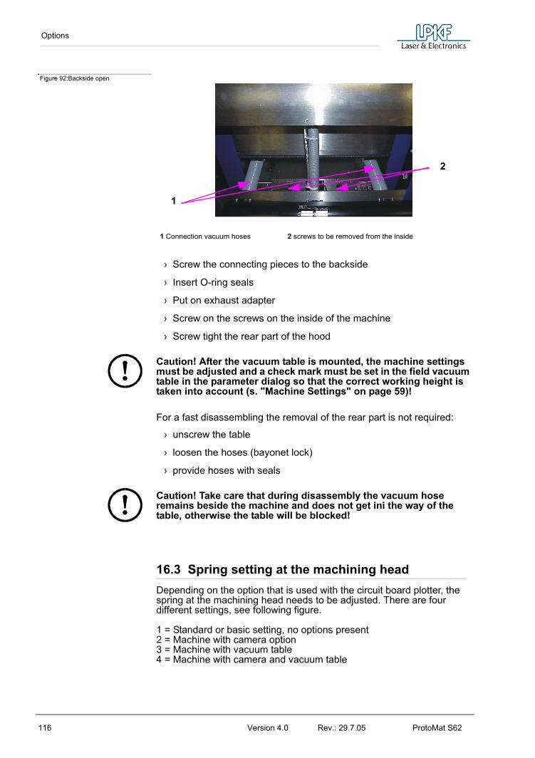
Options
116 Version 4.0 Rev.: 29.7.05 ProtoMat S62
Figure 92:Backside open
› Screw the connecting pieces to the backside
› Insert O-ring seals
› Put on exhaust adapter
› Screw on the screws on the inside of the machine
› Screw tight the rear part of the hood
Caution! After the vacuum table is mounted, the machine settings must be adjusted and a check mark must be set in the field vacuum table in the parameter dialog so that the correct working height is taken into account (s. "Machine Settings" on page 59)!
For a fast disassembling the removal of the rear part is not required:
› unscrew the table
› loosen the hoses (bayonet lock)
› provide hoses with seals
Caution! Take care that during disassembly the vacuum hose remains beside the machine and does not get ini the way of the table, otherwise the table will be blocked!
16.3 Spring setting at the machining headDepending on the option that is used with the circuit board plotter, the spring at the machining head needs to be adjusted. There are four different settings, see following figure.
1 = Standard or basic setting, no options present2 = Machine with camera option3 = Machine with vacuum table4 = Machine with camera and vacuum table
1 Connection vacuum hoses 2 screws to be removed from the inside
1
2

Options
ProtoMat S62 Version 4.0 Rev.: 29.7.05 117
Figure 93: Spring adjustment, machining head view from the right side
› To adjust the spring, loosen the screw (6 in figure above) and let the spring engage in the position according to the option that is used. Then tighten screw again.
1--4 Spring settings 6- Spring adjustment screw 5- Spring head
12345
6

Technical Data
118 Version 4.0 Rev.: 29.7.05 ProtoMat S62
17.0 Technical Data
Machine operating voltage: ........... 100-140 VAC / 200-260 VACPower consumption: ...................... 300 VASpeed of machining spindle:.......... 15.000 - 62.000 rpm. Permissible humidity:..................... max. 60%Operating temperature: ................. 15-25°C (59-77°F)Weight (without/with hood): ........... 42 kg / 55 kgDimensions (WxHxD): ................... 650 x 520 x 750 mmAirborne noise at workplace: ......... 71dB (A) without vacuumMinimum conductor width:............. 0.1 mmMinimum conductor interval:.......... 0.1 mmMinimum hole diameter: ................ 0.15 mmMotion range:................................. 12“ x 9“Repetition accuracy: ...................... +/- 2.5 µmPositioning accuracy...................... +/- 5 µm(after warming-up phase)Machining spindle:......................... EC motor 15,000-62,000/min.Tool change: .................................. Automatic (10 stations)Tool mount: .................................... 1/8“ clamping colletDrilling capacity: ............................ max. 150 strokes/min.Resolution (minimum motion step):0.00025 mm (0.25µm)Motion rate:.................................... 150 mm /sec. (max.)Milling depth adjustment:............... mechanical sensing, manuallyX/Y drive: ....................................... Incremental motors, precision ....................................................... spindleZ stroke:......................................... approx. 38 mm Applications: All 1 and 2-sided types of circuit
board with usual equipment density (FR3, FR4,FR5, G10), flexiblesubstrates, RF-substrates,millingcut-outs in front-panels, drilling testadapters, structuring film layouts,solder frames for PCB assembly, aswell as SMD fine conductortechnology, contour milling, frontpanel/plate engraving,multilayer upto 8 layers incombination with LPKFMiniContac and MultiPress

Declaration of Conformity
ProtoMat S62 Version 4.0 Rev.: 29.7.05 119
18.0 Declaration of Conformity
EC Declaration of Conformity
according to EU Machine Guidelines 98/37 EC.
Manufacturer LPKF Laser & Electronics AGOsteriede 730827 GarbsenGermany
herewith declares that the following productProduct name circuit board plotterSeries / Type designation ProtoMat S62
is a machine according to EU Machine Guideline 98/37 EC.Any modification to the designated machine not coordinated with manufacturer invalidates this declaration for this machine.
We maintain a quality assurance system certified by Daimler-Chrysler according to ISO 9001 and have therefore observe the following EC Guidelines and EN Standards in development and production of the machine:
EC Guidelines:
• EC Machine Guidelines 98/37 EC
• Low voltage operating equipment 73/23 EEC
• EMC 89/336 EEC
Harmonized Standards:
CE approval symbol was attached to the machine in accordance with Guideline 97/37 EC.
Garbsen, 10.02.2005
Bernd Hackmann (CEO)
This Declaration confirms conformance with the specified guidelines, however, is not a guarantee of properties. The safety precautions in the product documentation supplied are to be observed..
• EN 292-1 • EN 292-2• EN 349 • EN 614-1• EN 626-1 • EN 1050:1996• EN 60204- • EN 61000-6-1:2001• EN 61000-6-2:2001 • EN 61000-6-4:2001 • EN 55022:1994 A2 • 1

Declaration of Conformity
120 Version 4.0 Rev.: 29.7.05 ProtoMat S62

Index
ProtoMat S62 Version 4.0 Rev.: 29.7.05 121
19.0 Index
A
Airborne noise ................................................................................................. 118
BBase material ..........................................................................................5, 35, 81Baudrate ..............................................................................................................22BMaster ................................................................................................................28BoardMaster .................................................................................................. 5, 11Bringing into service ......................................................................................26
CCamera ............................................................................................. 56, 64, 89, 112Camera functions ............................................................................................54Camera offset ....................................................................................................64Caution .............................................................................................................4, 17Centering a project .........................................................................................74Centering project .............................................................................................74CircuitCAM ...........................................................................................................5Cleaning ...............................................................................................................86Configuration .....................................................................................................68Control functions .............................................................................................53Conventions .........................................................................................................4Copper laminate ................................................................................................5Create project ...................................................................................................71
DDanger ....................................................................................................................4Data ........................................................................................................................28Deleting a project ............................................................................................74Dimensions ....................................................................................................... 118Display scroll bars ..........................................................................................35Drilling ...................................................................................................................83
EEngraving ............................................................................................................98
FFeed rate .............................................................................................................63FIFO .......................................................................................................................22Font ........................................................................................................................78Front view ............................................................................................................21Function bar .......................................................................................................35
HHardware-Handshake ...................................................................................59Head downtime ................................................................................................62HOME position ...........................................................................................29, 56HP-GL ...................................................................................................................69
IIII ................................................................................................................................4Intended Use .......................................................................................................5

Index
122 Version 4.0 Rev.: 29.7.05 ProtoMat S62
JJob .......................................................................................................................... 34
LLayer ...................................................................................................................... 72Life cycle .............................................................................................................. 62Light dot ............................................................................................................... 64LMD ........................................................................................................................69Load ....................................................................................................................... 66Loops ..................................................................................................................... 87LPR ......................................................................................................................... 69
MMachine greenhorn .......................................................................................... 5Menu bar ............................................................................................................. 35Milling ........................................................................................................ 83, 84, 98Milling depth ....................................................................................................... 87Motion range ...................................................................................................... 35
NNote ..........................................................................................................................5
OOperating temperature ............................................................................... 118Optimal speed ................................................................................................... 63Origin ..................................................................................................................... 73
PParameter ........................................................................................................... 50PAUSE position ................................................................................................ 56Permissible humidity ................................................................................... 118Phase file ............................................................................................................. 72Phases .................................................................................................................. 65Placement ........................................................................................................... 73Power consumption ..................................................................................... 118Processor ............................................................................................................26Production phase ............................................................................................ 78
RRotation .......................................................................................................... 63, 73
SSafety Notes ...................................................................................................... 14Scale ...................................................................................................................... 73Serial interface ................................................................................................. 57Service .................................................................................................................. 96Set ........................................................................................................................... 67Solder resist foil ................................................................................................. 5Solder resist foils ............................................................................................. 98Sources of error ............................................................................................... 87Spacer ring ......................................................................................................... 82Start line ............................................................................................................... 61Status bar ............................................................................................................35Symbols ................................................................................................................. 4
TTarget Group ........................................................................................................ 5Teach-in ..............................................................................................................109

Index
ProtoMat S62 Version 4.0 Rev.: 29.7.05 123
Terminology ..........................................................................................................5Title bar .................................................................................................................34Tool changing position ............................................................................35, 56Tool Parameter .................................................................................................61Tutor.job ...............................................................................................................34
UUSB ........................................................................................................................26USB cable .....................................................................................................16, 23USB connection .........................................................................................19, 23USB driver ...........................................................................................................28USB repeater ...............................................................................................16, 23
VVacuum .................................................................................................................82Vacuum system ................................................................................................16Vacuum Table .................................................................................................. 114Vector index .......................................................................................................50
WWeight ................................................................................................................. 118Windows ..............................................................................................................26Working Depth Limiter ................................................................................104workplace ............................................................................................................14
XX Offset .................................................................................................................64
YY=>-Y ....................................................................................................................72
ZZoom area ...........................................................................................................77

Index
124 Version 4.0 Rev.: 29.7.05 ProtoMat S62