Embed Size (px)
Citation preview

INSTALLATION AND MAINTENANCE
Part number: 3225 en - 2017.08 / i
LSPX-FLSPX ZONE 21LS-FLS ZONE 22
Installation and maintenance
3-phase induction motors for atmospheres containing explosive dust
2
Installation and maintenance - LSPX-FLSPX ZONE 21 – LS-FLS ZONE 223225 en - 2017.08 / i
IMPORTANT
These symbols appear in this document whenever it is important to take special precautions during installation, operation, maintenance or servicing of the motors.
It is essential that electric motors are installed by qualified, experienced and authorised personnel.
In accordance with the main requirements of the EC Directives, the safety of people, animals and property should be ensured when fitting the motors into machines.
Particular attention must be given to equipotential ground or earthing connections.
The noise level of the machines, measured under standard conditions, conforms to the requirements of the standard and does not exceed the maximum value of 85 dB(A) pressure at 1 metre.
The following preliminary precautions must be taken before working on any stationary device:• Mains voltage disconnected and no residual voltage present• Careful examination of the causes of the stoppage (jammed transmission - loss of phase - cut-out due to thermal protection - lack of lubrication, etc)
Electric motors are industrial products. They must therefore be installed by qualified, experienced and authorised personnel. The safety of people, animals and property must be ensured when fitting the motors into machines (please refer to current standards).
Those persons required to work on electrical installations and equipment in zones where there is a risk of explosion must be specially trained and authorised for this type of equipment.They must be familiar with not only the electrical risks, but also with those that are due to the chemical properties and physical characteristics of the products used in the installation (gas, vapour, dust), as well as the environment in which the equipment operates. These elements determine the risk of fire and explosion.
In particular, they must be informed and aware of the reasons for the specific safety instructions in order to comply with them. For example:- Do not open when powered up- Do not open when powered up in atmospheres containing explosive dust- Do not repair while powered up- Do not move when on load- Wait for a few minutes before opening- Replace the seals tightly to ensure watertightness
Before commissioning, ensure compatibility of the information on the motor nameplate with the actual explosive atmosphere and the operating zone.
NOTE:LEROY-SOMER reserves the right to modify the characteristics of its products at any time in order to incorporate the latest technological developments. The information contained in this document may therefore be changed without notice.
Copyright 2004: LEROY-SOMERThis document is the property of LEROY-SOMER.
It may not be reproduced in any form without prior authorisation.
INSTALLATION AND MAINTENANCE - LSPX-FLSPX ZONE 21 – LS-FLS ZONE 22
3
Installation and maintenance - LSPX-FLSPX ZONE 21 – LS-FLS ZONE 223225 en - 2017.08 / i
All brands and models have been registered and patents applied for.
Dear Customer,
You have just acquired a LEROY-SOMER safety motor.
These motors benefit from the experience of one of the largest manufacturers in the world, using state-of-the-art technology in automation, specially selected materials and rigorous quality control. As a result, the regulatory authorities have awarded our motor factories the ISO 9001 - Edition 2008 international certificate.
We thank you for making this choice, and would ask you to read the contents of this manual.
By observing a few essential rules, you will ensure problem-free operation for many years.
LEROY-SOMER
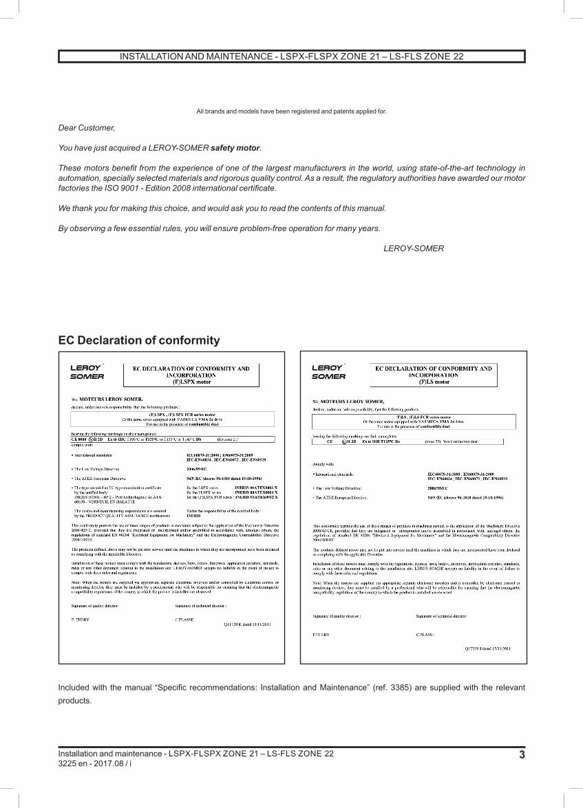
EC Declaration of conformity
Included with the manual “Specific recommendations: Installation and Maintenance” (ref. 3385) are supplied with the relevant products.
INSTALLATION AND MAINTENANCE - LSPX-FLSPX ZONE 21 – LS-FLS ZONE 22

4
Installation and maintenance - LSPX-FLSPX ZONE 21 – LS-FLS ZONE 223225 en - 2017.08 / i
CONTENTS
1 - RECEIPT ....................................................................... 51.1 - Identification and marking ................................................. 5
2 - STORAGE .................................................................... 6
3 - COMMISSIONING ....................................................... 6
4 - INSTALLATION ............................................................ 74.1 - Position of the lifting rings ................................................. 74.2 - Location - ventilation ......................................................... 84.3 - Coupling ........................................................................... 8
5 - ELECTRICAL PARAMETERS - LIMIT VALUES ...... 105.1 - Limiting problems caused by motor starting ....................... 95.2 - Supply voltage .................................................................. 95.3 - Starting times ..................................................................... 95.4 - Supply by frequency inverter ............................................. 9
6 - USE ............................................................................. 10
7 - SPECIAL OPERATING CONDITIONS ..................... 117.1 - Use with a variable speed drive ....................................... 12
8 - SET-UP ........................................................................ 13
9 - SUPPLY CONNECTION ............................................. 159.1 - Terminal box .................................................................... 159.2 - Wiring diagram for terminal block or isolators .................. 169.3 - Direction of rotation ......................................................... 169.4 - Earth terminal .................................................................. 169.5 - Connecting the power supply cables
to the terminal block ....................................................... 16
10 - MAINTENANCE ....................................................... 1710.1 - General information ...................................................... 1710.2 - Corrective maintenance: general information ................ 1810.3 - Safety regulations .......................................................... 1910.4 - Routine maintenance ..................................................... 1910.5 - Bearing maintenance ..................................................... 2010.6 - IP protection for the motor .............................................. 2010.7 - Troubleshooting guide ................................................... 21
11 - LSPX MOTORS ........................................................ 2211.1 - LSPX 63 to LSPX 160 MP/LR motors ............................ 2211.2 - LSPX 160 M/L, LSPX 180 MT/LR motors ...................... 2411.3 - LSPX 180 L, LSPX 200,
LSPX 225 ST/MT/MR motors......................................... 2611.4 - LSPX 225 MG, LSPX 250 ME/MF,
LSPX 280 SC/MC/MD motors ....................................... 28
12 - FLSPX MOTORS ..................................................... 3012.1 - FLSPX 80 to FLSPX 132 motors .................................... 3012.2 - FLSPX 160 and 180 motors ........................................... 3212.3 - FLSPX 200 and 225 MT/MS motors .............................. 3412.4 - FLSPX 225 M to 280 motors .......................................... 3612.5 - FLSPX 315 to 355 LD motors ........................................ 38
13 - LS AND FLS MOTORS - ZONE 22 ........................... 41
INDEX
Adjustments....................................................................................13Alarms - early warning ....................................................................10
Balancing..........................................................................................8Belts................................................................................................14Built-in thermal protection ...............................................................10
Cable gland.....................................................................................15Cables ............................................................................................16Capacitors ......................................................................................19Connection .....................................................................................16Connection diagrams ......................................................................16Corrective maintenance ..................................................................18Coupling ...........................................................................................8Coupling sleeves ............................................................................13
Digistart .......................................................................................... 11Direction of rotation .........................................................................16Draining condensation water ..........................................................19
Earth ........................................................................................ 11 - 16Earth terminal .................................................................................16End shields .............................................................................. 19 - 20European directives ..................................................................... 3 - 5
Frequency inverter ..........................................................................12
Greasing - Grease nipples .................................................. 6 - 19 - 20
Identification .....................................................................................5Inertia flywheel ................................................................................13Insulation .........................................................................................6
Lifting ring .........................................................................................7Location ...........................................................................................8Lubrication ......................................................................................20
Mains connection ..................................................................... 15 - 16Materials handling........................................................................ 7 - 8Mounting ...........................................................................................6
Nameplate ........................................................................................5
Power ...............................................................................................9Power supply ............................................................................. 9 - 16Protection .......................................................................................10Pulleys ............................................................................................14
Receipt .............................................................................................5Routine maintenance ......................................................................19
Shield fixing rods or screws -- tightening ........................................18Space heaters.................................................................................10Spare parts .....................................................................................17Starting .............................................................................................9Storage .............................................................................................6
Terminal box ..................................................................................15Terminal box -- tightening the screws ..............................................16Tolerances ......................................................................................13Troubleshooting .............................................................................21
Ventilation .........................................................................................8
INSTALLATION AND MAINTENANCE - LSPX-FLSPX ZONE 21 – LS-FLS ZONE 22

5
Installation and maintenance - LSPX-FLSPX ZONE 21 – LS-FLS ZONE 223225 en - 2017.08 / i
1 - RECEIPT1.1 - Identification and markingIf there are obvious signs of knocks, contact the carrier (you may able to claim on their insurance) and after a visual check, turn the motor by hand to detect any malfunction.
As soon as you receive the motor, check that the nameplate on the machine conforms to your order.
DE:NDE: g. / h.
3 LSPX132 M T N°0123456J11 0012011 IP65 IK08
40 °C Ins. cl. F S1 1000m 93kg0080
HS50
A_10
0-a
IEC
6003
4-1
V Hz min-1 kW cos ϕ A
A H
230400460
505060
146014601765
7,507,507,50
0,830,830,81
25,4014,7012,85
INERIS 00ATEX0003XII 2 D Ex tb IIIC T125°C Db
CTP150°C ; -40°C<Ta<50°C ; T.câble=100°C
F - 16015 ANGOULEME
DE:NDE: g. / h.
3 LS132 M T N°0123456J11 0012011 IP55 IK08
40 °C Ins. cl. F S1 1000m 93kg0080
HS50
A_10
0-a
IEC
6003
4-1
V Hz min-1 kW cos ϕ A
A H
230400460
505060
146014601765
7,507,507,50
0,830,830,81
25,4014,7012,85
II 3 D Ex tc IIIB T125°C Dc
CTP150°C ; -40°C<Ta<50°C ; T.câble=100°C
F - 16015 ANGOULEME
Definition of symbols used on nameplates:
Legal mark of conformity of product to the requirements of European Directives.
ATEX specific marking : Specific marking for protection against risks of explosion
II 2D or II 3D : Group and category of equipmentEx : Symbol for equipment designed for potentially explosive atmospherese : Protection typetb or tc : «dust» casing protection typeIII B or III C : Material groupT125°C : Maximum surface temperatureDb or Dc : EPL «dust» level0080 : Notified Body INERISINERIS 00ATEX003X : EC type-examination certificate numberMotorMOT 3 ~ : Three-phase A.C. motorLS-LSPXFLS-FLSPX : Series132-355 : Frame sizeS-LB : Housing symbolTR-T : Impregnation indexNo. : Serial number
L* : Year of productionA** : Month of production
* L = 2000, M = 2001 ... W = 2009, X = 2010**A = January, F = June
IP55 IK08 orIP65 IK08 : Degree of protection(I) cl. F : Insulation class F40°C : Ambient operating temperatureS : Duty% : Operating factor...d/h : Number of cycles per hourkg : WeightV : Supply voltageHz : Supply frequencymin-1 : Revolutions per minute (rpm)kW : Rated output powercos j : Power factorA : Rated currentD : Delta connectionY : Star connection
Bearings DE : Drive end Drive end bearingNDE : Non drive end bearing
Zone 21Zone 22
Zone TypeATEX
marking
Marking of protection
type
Max.surfaceT°C
E.P.L.level
Protection index
ATEX 21 (F)LSPX II 2 D EX tb IIIC T125°C Db IP 65
ATEX 22(F)LS
Non-conductive dust
II 3 D EX tc IIIB T125°C Dc IP 55
INSTALLATION AND MAINTENANCE - LSPX-FLSPX ZONE 21 – LS-FLS ZONE 22

6
Installation and maintenance - LSPX-FLSPX ZONE 21 – LS-FLS ZONE 223225 en - 2017.08 / i
2 - STORAGEPrior to commissioning, machines should be stored: - Away from humidity: at relative humidity levels above 90%, the machine insulation can drop very rapidly, to just above zero at around 100%. The state of the anti-rust protection on unpainted parts should be monitored.For very long storage periods the motor can be placed in a sealed enclosure (for example heat-shrunk plastic) containing sachets of desiccant:- Away from frequent significant variations in temperature, to avoid the risk of condensation. During storage the drain plugs must be removed to allow condensation water to escape.- If the area is subject to vibration, try to reduce the effect of this vibration by placing the motor on a damping support (rubber plate or similar) and turn the rotor a fraction of a turn once a fortnight to prevent the bearing rings from becoming marked. Remove and replace the rotor locking device if applicable.- Do not remove the rotor locking device (where there are roller bearings).Even if the motor has been stored in the correct conditions, certain checks must be carried out before it is started up:
GreasingBearings which cannot be regreasedMaximum storage: 3 years. After this time, replace the bearings and the seals on the spigots and shaftways (see section 10.3).
Regreasable bearings (instructions on nameplate)
Grade 2 grease
Grade 3 grease
Stor
age
perio
d
less than 6 months
less than 1 year
The motor can be commissioned without regreasing
more than 6 months less than
1 year
more than 1 year
less than 2 years
Regrease before commissioning, as described in section 10.4.1
more than 1 year
less than 5 years
more than 2 years
less than 5 years
Dismantle the bearing- Clean it- Replace the grease completely- Replace the spigot and shaft
seals (see section 10.2.2)
more than 5 years
more than 5 years
Change the bearing- Regrease it completely- Replace the spigot and shaftway
seals
Warning: Dot not perform a high voltage test on the auxiliaries.
3 - COMMISSIONINGBefore starting the motor, it is advisable to check the insulation between the phases and earth, and between phases.
This check is essential if the motor has been stored for longer than 6 months or if it has been kept in a damp atmosphere.This measurement must be carried out using a megohmmeter at 500 V D.C. (do not use a magnetoelectric system).It is better to carry out an initial test at 30 or 50 volts and if the insulation is greater than 1 megohm, carry out a second test at 500 volts for 60 seconds. The insulation value must be at least 10 megohms in cold state.If this value cannot be achieved, or if the motor may have been splashed with water or salt spray, or kept for a long period in a very humid place or if it is covered with condensation, it is advisable to dry the stator for 24 hours in a drying oven at a temperature of between 110°C and 120°C.If it is not possible to place the motor in a drying oven:- Switch on the motor, with the rotor locked, at 3-phase A.C. voltage reduced to approximately 10% of the rated voltage, for 12 hours (use an induction regulator or a reduction transformer with adjustable outlets). - Or supply the 3 phases in series with a D.C. current, with the voltage at 1 to 2% of the rated voltage (use a D.C. generator with independent excitation or batteries for motors of less than 22 kW).- NB: The A.C. current must be monitored using a clamp ammeter, and the D.C. current using a shunt ammeter. This current must not exceed 60% of the rated current.It is advisable to place a thermometer on the motor housing: if the temperature exceeds 70°C, reduce the indicated voltage or current by 5% of the original value for every 10°C difference.While it is drying, all the motor orifices must be open (terminal box, drain holes). Before commissioning, all these covers must be replaced so that the motor conforms to the degree of protection specified on the nameplate. Clean the plugs and orifices before reassembly.
Warning: If the high voltage test, carried out at the factory before despatch, needs to be repeated, it
should be performed at half the standard voltage, ie: 1/2 (2U+1000V). Check that the capacitive effect resulting from the high voltage test is eliminated before connecting the terminals to earth.
Before commissioning: for all motors:- Remove all dust from the machine
- Rotate the motor with no load (no mechanical load) for 2 to 5 minutes, checking that there is no abnormal noise. If there is any abnormal noise, see section 10.
M
INSTALLATION AND MAINTENANCE - LSPX-FLSPX ZONE 21 – LS-FLS ZONE 22

7
Installation and maintenance - LSPX-FLSPX ZONE 21 – LS-FLS ZONE 223225 en - 2017.08 / i
4 - INSTALLATION4.1 - Position of the lifting rings
The lifting rings are intended for lifting the motor on its own. They must not be used to lift the whole
machine once the motor has been fitted to it.
Labour regulations stipulate that all loads over 25 kg must be fitted with lifting devices to facilitate handling.The positions of the lifting rings and the minimum dimensions of the loading bars are given below in order to help with preparation for handling the motors. If these precautions are not followed, there is a risk of warping or crushing some equipment such as the terminal box, cover or drip cover.
• Horizontal position
TypeHorizontal position
A e min. h min. Øt100 120 200 150 9112 120 200 150 9132 160 200 150 9160 200 160 110 14
180 MR 200 160 110 14180 L 200 260 150 14200 270 260 165 14
225 ST/MT/MR 270 260 150 14225 M 360 265 200 30
225 MG 400 400 500 30250 MZ 270 260 150 14
250 360 380 200 30225 MG 400 400 500 30
250 ME/MF 400 400 500 30280 360 380 500 30
280 SC/MC/MD 400 400 500 30315 ST 310 380 500 17315 M/L 360 380 500 23
355 310 380 500 23
Motors intended for use in the vertical position may be delivered in the horizontal position on a pallet.
When the motor is pivoted, the shaft must under no circumstances be allowed to touch the ground, as the bearings may be irreparably damaged.
• Vertical position
View from above Side view
TypeVertical position
C E D N ØS e min.* h min.160 320 200 230 2 14 320 350
180 MR 320 200 230 2 14 320 270180 L 390 265 290 2 14 390 320200 410 300 295 2 14 410 450
225 ST/MT/MR 410 300 295 2 14 410 450225 M 480 360 405 4 30 540 350
225 MG 500 400 502 4 30 500 500250 MZ 410 300 295 2 14 410 450
250 480 360 405 4 30 540 350250 ME/MF 500 400 502 4 30 500 500
280 S 480 360 485 4 30 590 550280 M 480 360 585 4 30 590 550
280 SC/MC/MD 500 400 502 4 30 500 500315 ST 590 - 590 2 17 630 550315 M/L 695 - 765 2 24 695 550
355 755 - 835 2 24 755 550* if the motor is fitted with a drip cover, allow an additional 50 to 100 mm to avoid damaging it when the load is swung.
e
A
h
2 x Øt
e
h
n x ØS
D
E
C
INSTALLATION AND MAINTENANCE - LSPX-FLSPX ZONE 21 – LS-FLS ZONE 22

8
Installation and maintenance - LSPX-FLSPX ZONE 21 – LS-FLS ZONE 223225 en - 2017.08 / i
4.2 - Location - ventilationOur motors are cooled in accordance with method IC 411 (standard IEC 60034-6) ie. “machine cooled by the surface, using the ambient fluid (air) flowing along the machine”.The fan at the non drive end cools the motor. Air is sucked in through the grille of a fan cover (which provides protection against the risk of direct contact with the fan in accordance with standard IEC 60034-5) and blown along the housing fins to ensure thermal equilibrium of the motor whatever the direction of rotation.
The motor must be installed in an adequately ventilated area, with clearance for the air intake and outlet of at least one-quarter of the frame size.Blocking the fan cover grille and the housing fins, even accidentally (clogging), is likely to adversely affect the operation and safety of the motor.In the case of vertical operation with the shaft extension facing down, it is advisable to fit the motor with a drip cover to prevent the entry of any foreign bodies.It is necessary to check that the hot air is not being recycled. If it is, pipes must be provided for the intake of cold air and discharge of hot air, in order to prevent abnormal temperature rise of the motor.In this case, if the air is not circulated by an auxiliary fan, the dimensions of the pipes must be such that the load losses are negligible compared to those of the motor.PositioningThe motor must be mounted in the position specified on the order, on a base which is rigid enough to prevent distortion and vibration.Where the motor feet have six fixing holes, it is preferable to use those which correspond to the standard dimensions for the motor power rating (refer to the technical catalogue for induction motors) or, failing that, to those shown at B2.
Provide easy access to the terminal box, the condensation drain plugs and, if appropriate, to the grease nipples.
Use lifting equipment which is compatible with the weight of the motor (indicated on the nameplate).
When the motor is fitted with lifting rings, they are for lifting the motor on its own and must not be
used to lift the whole machine after the motor has been fitted to it.Note 1: When installing a suspended motor, it is essential to provide protection in case the fixing breaks.Note 2: Never stand on the motor.
4.3 - CouplingPreparationTurn the motor by hand before coupling to detect any possible fault due to handling.Remove any protection from the shaft extension.
Drain off any condensation water which may have formed inside the motor by removing the plugs from the drain holes. Before commissioning, these plugs must be replaced and the motor must conform to the specified degree of protection.
Rotor locking device For made-to-order motors with roller bearings, remove the rotor locking device.In exceptional circumstances when the motor has to be moved after the coupling device has been fitted, the rotor must be re-immobilised.
BalancingRotating machines are balanced according to standard IEC 34-14:- Half-key when the shaft extension is marked HBy special request, the balancing can be set:- No key when the shaft extension is marked N- Full key when the shaft extension is marked F Any coupling element (pulley, coupling sleeve, slip-ring, etc) must therefore be balanced accordingly.Motor with 2 shaft extensions: If the second shaft extension is not used, in order to comply with the balancing class, the half-key or key must be fixed firmly in the keyway so that it is not thrown out during rotation (H or F balancing) and must be protected against direct contact.
1/4 H min
H
B 2B 1
INSTALLATION AND MAINTENANCE - LSPX-FLSPX ZONE 21 – LS-FLS ZONE 22

9
Installation and maintenance - LSPX-FLSPX ZONE 21 – LS-FLS ZONE 223225 en - 2017.08 / i
5 - ELECTRICAL PARAMETERS - LIMIT VALUES
5.1 - Minimising motor starting problemsIn order to protect the installation, any significant temperature rise in the cabling conduits must be prevented, while ensuring that the protection devices are not triggered during starting.Operating problems in other equipment connected to the same supply are due to the voltage drop caused by the current demand on starting - many times greater than the current absorbed by the motor at full load (approximately 7). See the LEROY-SOMER induction motors technical catalogue.Even though mains supplies increasingly allow D.O.L. starting, the current inrush must be reduced for certain installations.Jolt-free operation and soft starting ensure greater ease of use and an increased lifespan for the machines being driven.The two essential parameters for starting cage induction motors are:- starting torque- starting currentThe starting torque and the resistive torque determine the starting time.Depending on the load being driven, it may be necessary to adapt the torque and the current to the machine starting time and to the possibilities of the mains power supply. The five essential modes are:- D.O.L. starting- Star/delta starting- Soft starting with autotransformer- Soft starting with resistors- Electronic starting
The "electronic" starting modes control the voltage at the motor terminals during the entire starting phase and enable very soft, jolt-free starting.
5.2 - Supply voltageThe rated voltage is indicated on the nameplate.
We guarantee the maximum surface temperature (see section 7) of our motors for a power supply at
a rated voltage ±10%.
5.3 - Starting timesThe starting times must remain within the limits shown below on condition that the number of starts per hour is 6 or less.Three successive cold starts and two consecutive warm starts are allowed.
Permissible motor starting time as a function of the ratio ID/IN for cold starts.
5.4 - Supply by frequency inverterSee section 7.1.
25
20
15
Tim
e (s
)
10
55 6 7 Id/In 8 9 10
Warm startCold start
INSTALLATION AND MAINTENANCE - LSPX-FLSPX ZONE 21 – LS-FLS ZONE 22
10
Installation and maintenance - LSPX-FLSPX ZONE 21 – LS-FLS ZONE 223225 en - 2017.08 / i
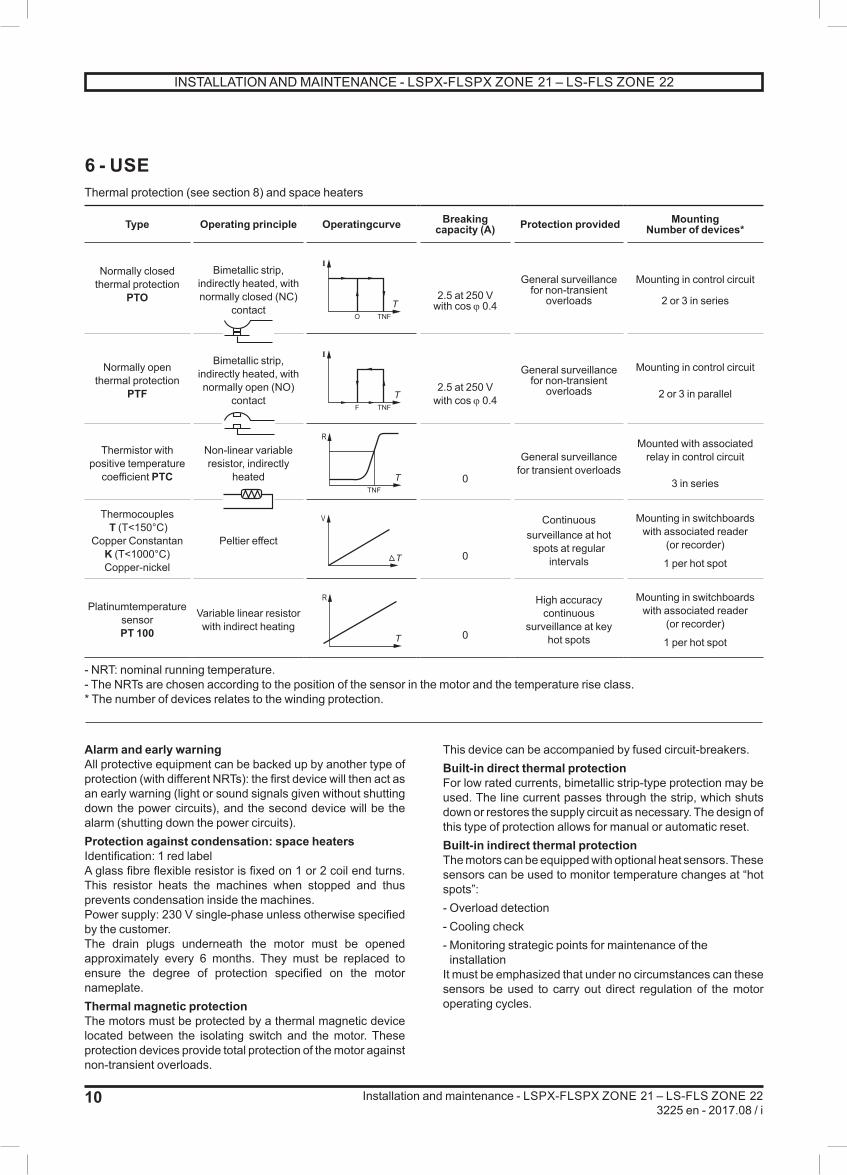
6 - USEThermal protection (see section 8) and space heaters
Type Operating principle Operatingcurve Breaking capacity (A) Protection provided Mounting
Number of devices*
Normally closed
thermal protectionPTO
Bimetallic strip, indirectly heated, with normally closed (NC)
contact
I
O TNF
T2.5 at 250 V
with cos j 0.4
General surveillance for non-transient
overloads
Mounting in control circuit
2 or 3 in series
Normally open thermal protection
PTF
Bimetallic strip, indirectly heated, with normally open (NO)
contact
I
F TNF
T2.5 at 250 V
with cos j 0.4
General surveillance for non-transient
overloads
Mounting in control circuit
2 or 3 in parallel
Thermistor with positive temperature
coefficient PTC
Non-linear variable resistor, indirectly
heated
R
TNFT 0
General surveillance for transient overloads
Mounted with associated relay in control circuit
3 in series
Thermocouples T (T<150°C)
Copper Constantan K (T<1000°C)Copper-nickel
Peltier effect
V
T 0
Continuous surveillance at hot
spots at regular intervals
Mounting in switchboards with associated reader
(or recorder)
1 per hot spot
Platinumtemperature sensorPT 100
Variable linear resistor with indirect heating
R
T 0
High accuracy continuous
surveillance at key hot spots
Mounting in switchboards with associated reader
(or recorder)
1 per hot spot
- NRT: nominal running temperature.- The NRTs are chosen according to the position of the sensor in the motor and the temperature rise class.* The number of devices relates to the winding protection.
Alarm and early warningAll protective equipment can be backed up by another type of protection (with different NRTs): the first device will then act as an early warning (light or sound signals given without shutting down the power circuits), and the second device will be the alarm (shutting down the power circuits).Protection against condensation: space heatersIdentification: 1 red labelA glass fibre flexible resistor is fixed on 1 or 2 coil end turns. This resistor heats the machines when stopped and thus prevents condensation inside the machines. Power supply: 230 V single-phase unless otherwise specified by the customer.The drain plugs underneath the motor must be opened approximately every 6 months. They must be replaced to ensure the degree of protection specified on the motor nameplate.Thermal magnetic protectionThe motors must be protected by a thermal magnetic device located between the isolating switch and the motor. These protection devices provide total protection of the motor against non-transient overloads.
This device can be accompanied by fused circuit-breakers. Built-in direct thermal protectionFor low rated currents, bimetallic strip-type protection may be used. The line current passes through the strip, which shuts down or restores the supply circuit as necessary. The design of this type of protection allows for manual or automatic reset. Built-in indirect thermal protectionThe motors can be equipped with optional heat sensors. These sensors can be used to monitor temperature changes at “hot spots”:- Overload detection- Cooling check- Monitoring strategic points for maintenance of the installation
It must be emphasized that under no circumstances can these sensors be used to carry out direct regulation of the motor operating cycles.
INSTALLATION AND MAINTENANCE - LSPX-FLSPX ZONE 21 – LS-FLS ZONE 22

11
Installation and maintenance - LSPX-FLSPX ZONE 21 – LS-FLS ZONE 223225 en - 2017.08 / i
7 - SPECIAL OPERATING CONDITIONS- Installation zonesOur motors have IP65 (or IP55 - zone 22) protection and we can guarantee their surface temperature. They are thus designed for use in group II atmospheres containing explosive dust - category 2 (IP65 - zone 21) or category 3 (IP55 - zone 22).
- Safety of personnelProtect all rotating devices before power-up.If a motor is started up without a coupling device having been fitted, carefully immobilise the key in its location. All measures must be taken to ensure protection against the risks which arise when there are rotating parts (coupling sleeve, pulley, belt, etc).Beware of backdriving when the motor is switched off. The appropriate precautions must be taken:- For example, for pumps a non-return valve must be installed.
- Thermal protection (see sections 6 & 8)In frequent or difficult starting conditions, motors must be fitted with thermal protection.
- Space heaters (see section 6)Space heaters should only be used when the motor is cold and at a standstill.
- Temperatures: storage and ambientNote: Ta = Ambient temperatureIf the motor has been stored at a temperature lower than -10°C, heat it (see section 3) and turn the shaft manually before starting up the machine.If the motor is to be used at a temperature lower than -25°C, if must not be fitted with a sensor. It can be equipped with thermocouples.Our standard motors are designed to operate at an ambient temperature Ta of between -20°C and 40°C.If Ta < -25°C, the shaftway seals must be made of silicon and the fan must be metal.If Ta < -25°C or (and) if 50°C < Ta ≤ 60°C, the flat seals of the terminal box must be out of silicon.
- Surface temperatureAs standard, the maximum surface temperature of our motors is 125°C with a maximum ambient temperature of ≤ 40°C. Without adapting the motor, the maximum surface temperature will be:• 135°C if 40°C ≤ Ta ≤ 50°C • 145°C if 50°C ≤ Ta ≤ 60°C
- ConnectionParticular attention must be paid to the information on the nameplate in order to choose the correct type of connection for the supply voltage.When the motor is fitted with one or more auxiliary junction boxes, it may only tolerate a low risk of mechanical danger, and the user will need to provide additional protection if there is a high level of risk.
- EarthingIt is compulsory to earth the motor, and earthing must be performed in accordance with current regulations (protection of workers).
- SealsIf the drain plugs are removed, they must be replaced in order to ensure that the motor conforms to the degree of protection specified on the nameplate. Replace the seals which have been removed with new seals of the same type. Clean the holes and plugs before reassembly. Each time the motor is dismantled (once a year depending on the application), it is advisable to replace the seals on the shaftways, the shield spigots and the terminal box cover with new seals of the same type after cleaning all parts. The seals on the shaftways must be fitted using the same type of grease as on the bearings.
- Resistance to shocksThe motor can withstand a weak mechanical shock (IK 08 according to EN 50-102). The user must provide additional protection if there is a high risk of mechanical shock.Note: Possibility of ordering option IK 10.
- Operating positionWhen the motor is used in any position other than horizontal or vertical, the DE shield must be fitted with a thermal sensor.
- LEROY-SOMER "Digistart" electronic starterThis is a multi-function electronic system with a microcontroller, which is used with all 3-phase cage induction motors.It provides soft starting of the motor with:- Reduction of the starting current- Gradual, jolt-free acceleration, achieved by controlling the current absorbed by the motor.After starting, the DIGISTART performs additional motor control functions in its other operating phases: steady state and deceleration.- 18 to 1600 A models- Supply: 220 to 700 V - 50/60 HzDIGISTART is economical to install, as a fused switch is the only additional device needed.The "Digistart" electronic starter used with the motor must be installed outside danger zones (outside zones 20, 21 and 22).
- Contactors - isolatorsIn all cases, contactors, isolators, etc, must be installed and connected in an enclosure offering a degree of protection and surface temperature compatible with the installation zone, or outside danger zones (outside zones 20, 21 and 22).
- Auxiliary ventilationWhen the motor is fitted with auxiliary or forced ventilation, a device must be present to prevent the main motor from operating when there is no ventilation.
- SensorsWhen fitting sensor(s) (a vibration sensor for example), these should have a minimum of IP65 (zone 21) or IP55 (zone 22) protection. They should be connected to the external circuit inside a box, which provides the same degree of protection as the motor.
INSTALLATION AND MAINTENANCE - LSPX-FLSPX ZONE 21 – LS-FLS ZONE 22

12
Installation and maintenance - LSPX-FLSPX ZONE 21 – LS-FLS ZONE 223225 en - 2017.08 / i
7.1 - Use with a variable speed driveWhen a drive is used, any special instructions detailed in the specific drive manual must be observed. In particular, the following minimum steps must be taken:- Check that the drive switching frequency is at least 3 kHz.- Check that the motor has a second nameplate indicating the maximum motor characteristics and the motor performance when used with a variable speed drive.- The reference voltage, usually 400 V at 50 Hz, is indicated on the motor nameplate. The drive must deliver a constant voltage/frequency signal to the motor.- Program in the drive the maximum current value and also the min. and max. frequency values indicated on the second motor nameplate.- Connect all the temperature sensors on the motor (winding and possibly DE shields) to safety devices independent of those used for operation in normal conditions.
7.1.1 - Special conditions for safe operation- As standard, the motor shock resistance corresponds to a “low” risk of mechanical danger, and they should therefore be installed in an environment with a low risk of shocks.- The motor must be fitted with thermal sensors in the winding (all frame sizes) and on the DE bearing (frame size 160 and above) in the following cases:
- Motor supplied by a frequency inverter- Motor in a good air-flow (IC418) and not self-cooled- Motor adapted so as to no longer be self-cooled (IC410)- Motor fitted with a backstop.
So that the maximum surface temperature is never reached, the internal thermal sensors with the
material, when they are obligatory, must be connected to a device (in additional to and functionally independent of any system which could be required for operational reasons in normal conditions), which switches off the motor.
- When the motor is fitted with auxiliary or forced ventilation (IC416), a device must be present to prevent the main motor from operating when there is no ventilation.- The space heaters should only be supplied with power when the motor is switched off and cold; their use is recommended in ambient temperatures less than -20°C.- The supply voltage and frequency must conform to those indicated on the motor nameplate.- The frequency range specified on the motor nameplate must be strictly observed.
- When several motors are supplied by the same drive, individual protection must be provided on each motor starter (thermal relay for example), for safety reasons.
- When a frequency inverter is used, any special instructions detailed in its specific manual must be complied with.
- The cable glands should be compatible with the protection method used for the connection part. On variants with an integral cable(s), the motor must be connected outside the potentially explosive atmosphere, or inside a box protected by a suitable recognised protection method.
- Variable speedSpecial operating precautions must be taken when these motors are powered via a frequency inverter or voltage controller:
The reference voltage (drive output or motor input) is 400 V at 50 Hz. The drive must deliver a constant
voltage/frequency signal to the motor.
The supply voltages and frequency range specified on the motor nameplate must be strictly observed.
Drives and sensor connection devices must be placed outside danger zones (outside zones 20, 21
and 22).
If the motor is supplied by a separate frequency inverter, is used in a good air-flow, is adapted (if necessary) so as to no longer be self-cooled or is equipped with a backstop, then it must be fitted with thermal sensors in the winding (all frame sizes), on the DE bearing (frame size 160 and above), and, if necessary, on the NDE bearing.When the motor is fitted with auxiliary or forced ventilation, a device must be present to prevent the main motor from operating when there is no ventilation.When a drive is used, any special instructions detailed in the specific drive manual must be observed.When several motors are supplied by the same drive, provide individual protection on each motor starter (thermal relay) for safety reasons.VARMECA variable speed drives are preset in accordance with the selection guide ref. 3267. Any modification of the settings should be performed by a skilled operator, in accordance with this guide. The parameters of VARMECA variable speed drives must be strictly observed as indicated in the instruction manual.VARMECA variable speed drives incorporate thermal protection and do not require additional thermal protection integrated in the motor.
Drives and sensor connection devices must be placed outside danger zones (outside zones 0,
1, 2, 20, 21 and 22).
INSTALLATION AND MAINTENANCE - LSPX-FLSPX ZONE 21 – LS-FLS ZONE 22

13
Installation and maintenance - LSPX-FLSPX ZONE 21 – LS-FLS ZONE 223225 en - 2017.08 / i
8 - SET-UPTolerances and adjustmentsThe standard tolerances are applicable to the mechanical characteristics given in our catalogues. They comply fully with the requirements of IEC standard 60072-1.- Users must adhere strictly to the instructions provided by the transmission device supplier. - Avoid impacts which could damage the bearings.Use a spanner and the tapped hole of the shaft extension with a special lubricant (e.g. molykote grease) to make it easier to fit the coupling.
The hub of the transmission device must be:- Fully in contact with the shoulder of the shaft or, if this is missing, against the metal stop ring which forms a labyrinth seal and thus locks the bearing in place (do not crush the seal).- Longer than the shaft extension (2 to 3 mm) so that it can be tightened using a screw and washer. If it is not, a spacer ring must be inserted without cutting the key (if this ring is large, it must be balanced).
If there is a second shaft extension, it must only be used for direct coupling and the same recommendations must be followed.
The 2nd shaft extension may also be smaller than the main shaft extension, and under no
circumstances can it deliver torques greater than half the rated torque.
Inertia flywheels must not be mounted directly onto the shaft extension, but installed between end shields and connected by a coupling device.
Direct connection onto the machineWhen mounted directly on the motor shaft extension of the moving device (pump or fan turbine), check that this device is perfectly balanced and that the radial force and the axial thrust are within the limits indicated in the catalogue for bearing performance.
Direct connection using a flexible couplingSelection of the coupling sleeve should take account of the rated torque to be transmitted and the safety factor dependent on the starting conditions for the electric motor.The machines must be carefully aligned, so that any lack of concentricity and parallelism in the two parts of the coupling sleeve is compatible with the recommendations of the coupling sleeve manufacturer.Both coupling halves should be provisionally assembled to assist moving them in relation to one another.Adjust the parallel plane of both shafts using a gauge. Measure the distance between the two coupling surfaces at one point on the circumference. Rotate them 90°, 180° and 270° in relation to this initial position, and measure each time. The difference between the two extreme values of dimension “x” must not exceed 0.05 mm for standard couplings.
To perfect this adjustment and at the same time check the concentricity of the two shafts, fit 2 gauges as shown in the diagram and slowly turn both shafts.The differences registered by either shaft will indicate the need for an axial or radial adjustment if the difference exceeds 0.05 mm.Direct connection using a rigid couplingThe two shafts must be aligned so as to adhere to the tolerances of the coupling sleeve manufacturer.Maintain the minimum distance between the two shaft extensions to allow for expansion of the motor shaft and the load shaft.
A
Ø
Ø (mm) A (mm)min
9 to 55 1
60 1.5
65 1.5
75 2
80 2
x
Applied to shoulder of shaft
Applied to stop ring
INSTALLATION AND MAINTENANCE - LSPX-FLSPX ZONE 21 – LS-FLS ZONE 22

14
Installation and maintenance - LSPX-FLSPX ZONE 21 – LS-FLS ZONE 223225 en - 2017.08 / i
Transmission via belt pulleysThe user can choose the diameter of the pulleys.Cast iron pulleys with a diameter over 315 are not recommended for rotation speeds of 3000 min-1.Flat belts cannot be used for rotation speeds of 3000 min-1 or more.
Positioning the belts The belts must be antistatic and flame- resistant.
So that the belts can be correctly positioned, allow for possible adjustment of approximately 3% with respect to the calculated distance E.Force must never be used when fitting the belts.For notched belts, position the notches in the pulley grooves.
Aligning the pulleysCheck that the motor shaft is totally parallel to that of the receiving pulley.
Reminder:- Too much tension = unnecessary force on the end shields which could lead to premature wear of the bearing unit (end shield-bearings) and eventually break the shaft.- Too little tension = vibration (wearing of the bearing unit).
Fixed distance between centres: Place a belt tensioning pulley on the slack side of the belts:- Smooth pulley on the outside of the belt- Grooved pulley on the inside of the belts when using V-belts.
Adjustable distance between centres:The motor is usually mounted on slide rails, which enables optimum adjustment of the pulley alignment and the belt tension. Place the slide rails on a completely horizontal baseplate.The lengthways position of the slide rails is determined by the length of the belt, and the crossways position by the pulley of the machine being driven.Mount the slide rails firmly with the tension screws in the direction shown in the diagram (slide rail screw on the belt side between the motor and the machine being driven).Fix the slide rails onto the baseplate and adjust the belt tension as before.
Thermal protectionOn-line protection Setting the thermal protection (see section 6)This should be adjusted to the value of the current read on the motor nameplate for the connected mains voltage and frequency.
Warning: Whatever the type of protection used (PTO, PTF or PTC), its value must not exceed:
• 150°C max. for the stator and 120°C max. for the shields if the maximum surface temperature = 125°C.• 160°C max. for the stator and 130°C max. for the shields if the maximum surface temperature = 135°C.• 170°C max. for the stator and 140°C max. for the shields if the maximum surface temperature = 145°C.
If using sensors with variable resistances or thermocouples, the associated equipment must stop the motor when the temperature reaches:• 150°C max. for the stator and 120°C max. for the shields if the maximum surface temperature = 125°C.• 160°C max. for the stator and 130°C max. for the shields if the maximum surface temperature = 135°C.• 170°C max. for the stator and 140°C max. for the shields if the maximum surface temperature = 145°C.
To ensure conformity with the maximum surface temperature, the thermal sensors fitted on the
motor must be connected to a device which switches off the motor when the operating thresholds defined above are reached.
E
Protect all rotating devices before power-up.
Adjusting the tension of the beltsThe tension of the belts must be adjusted very carefully in accordance with the recommendations
of the belt supplier and the calculations made when the product was specified.
Vis tendeur
Vis tendeur
INSTALLATION AND MAINTENANCE - LSPX-FLSPX ZONE 21 – LS-FLS ZONE 22

15
Installation and maintenance - LSPX-FLSPX ZONE 21 – LS-FLS ZONE 223225 en - 2017.08 / i
Terminal box positions Cable gland positions
Cable size
Adapt the cable gland and its reducer or amplifier, if fitted, to the diameter of the cable being used, in
accordance with the manual specific to the cable gland.To maintain the original stated IP protection of the motor, it is essential to make a watertight seal between the rubber ring and the cable, by tightening the cable gland correctly (it should not be possible to unscrew it without a tool).Unused cable glands must be replaced with threaded plugs.Unused orifices must also be closed off using threaded plugs. When fitting cable glands or blocking holes, a seal of perbunan, or silicon or polyurethane mastic, must be inserted between the cable glands, the plugs, the reducers or (and) the amplifiers and the support or the terminal box.
The installer is responsible for the IP sealing of the cable path (see the motor nameplate and the instructions for assembling the cable gland).
A Positionstandard
2 4
1
3
Positionstandard
9 - SUPPLY CONNECTION9.1 - Terminal boxIf the thread(s) on the orifice(s) designed to take one or more cable glands or conduits is (are) metric, there will be no particular marking on the motor; if the thread type is different or mixed, the type(s) will be marked on the equipment.This is placed as standard on the top of the motor near the drive end. It has IP65 protection and is fitted with a cable gland.Warning: The position of the terminal box cannot be easily modified, even with flanged motors, as the condensation drain holes (if appropriate) must be at the bottom.
Cable gland (NFC 68-311 and 312 standards)The standard position of the cable gland (1) is on the right, seen from the motor drive end.If the non-standard position of the cable gland has not been correctly specified on the order, or is no longer suitable, the symmetrical construction of the terminal box enables it to be turned in any of the 4 directions except for position (2) on flange-mounted motors (B5).A cable gland must never open upwards.Check that the incoming bend radius of the cables prevents water entering via the cable gland.
NE PAS OUVRIR SOUS TENSIONNE PAS OUVRIR SI UNE ATMOSPHEREEXPLOSIVE PEUT ETRE PRESENTE
DO NOT OPEN WHEN ENERGIZEDDO NOT OPEN WHEN AN EXPLOSIVEATMOSPHERE MAY BE PRESENTE
AVERTISSEMENT
WARNING
ref.
HS
51A
31P
SI0
70E
A05
0
The motors are factory-fitted with guidance labels which must be kept clean and legible.
Under no circumstances should the power supply cable be used for handling the motor.
INSTALLATION AND MAINTENANCE - LSPX-FLSPX ZONE 21 – LS-FLS ZONE 22
16
Installation and maintenance - LSPX-FLSPX ZONE 21 – LS-FLS ZONE 223225 en - 2017.08 / i
9.2 - Wiring diagram for terminal block or isolatorsAll motors are supplied with a wiring diagram in the terminal box. If required, this diagram should be obtained from the supplier, specifying the motor type and number (shown on the motor nameplate).The connector links required for coupling can be found inside the terminal box.Single speed motors are fitted with a block with 6 conforming terminals or with isolators (with frame size ranging from 160 to 355), whose markings conform to IEC 60034-8 (or NFC 51-118).
9.3 - Direction of rotationWhen the motor is powered by U1, V1, W1 or 1U, 1V, 1W from a direct mains supply L1, L2, L3, it turns clockwise when seen from the drive shaft end.If 2 phases of the power supply are changed over, the motor will rotate anti-clockwise (the motor should be checked to ensure that it has been designed to rotate in both directions). If the motor is fitted with accessories (thermal protection or space heater), these can be connected either on certified mini-terminals, or on non-certified mini-terminals.
Motor fitted with a terminal block
9.4 - Earth terminalIt is compulsory to earth the motor, and earthing must be performed in accordance with current
regulations (protection of workers).
One earth terminal is located inside the terminal box, and another is outside the enclosure. They are marked by the symbol:
They must be protected against self-release by a lock washer, locknut or anti-vibration adhesive.None of the contact parts contain light alloy.The sizing of the cables must comply with the specifications of standard EN 50-281-1-1.
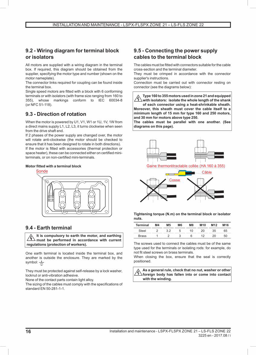
9.5 - Connecting the power supply cables to the terminal blockThe cables must be fitted with connectors suitable for the cable cross-section and the terminal diameter.They must be crimped in accordance with the connector supplier's instructions.Connection must be carried out with connector resting on connector (see the diagrams below):
Type 160 to 355 motors used in zone 21 and equipped with isolators: isolate the whole length of the shank of each connector using a heat-shrinkable sheath.
Moreover, this sheath must cover the cable itself to a minimum length of 15 mm for type 160 and 250 motors, and 30 mm for motors above type 250. The cables must be parallel with one another. (See diagrams on this page).
Tightening torque (N.m) on the terminal block or isolator nuts.
Terminal M4 M5 M6 M8 M10 M12 M16Steel 2 3.2 5 10 20 35 65Brass 1 2 3 6 12 20 50
The screws used to connect the cables must be of the same type used for the terminals or isolating rods: for example, do not fit steel screws on brass terminals.When closing the box, ensure that the seal is correctly positioned.
As a general rule, check that no nut, washer or other foreign body has fallen into or come into contact with the winding.
SondeGaine thermorétractable collée (HA 160 à 355)
Cosse
Câble
INSTALLATION AND MAINTENANCE - LSPX-FLSPX ZONE 21 – LS-FLS ZONE 22

17
Installation and maintenance - LSPX-FLSPX ZONE 21 – LS-FLS ZONE 223225 en - 2017.08 / i
10 - MAINTENANCE
10.1 - General information10.1.1 - Frequent monitoringThis monitoring, generally carried out by operators, is intended to:- Monitor, as a preventive measure, the state of the equipment (cables, cable glands, etc) bearing in mind the environmental conditions (temperature, humidity, etc).- Detect as early as possible any potentially dangerous problems, such as damage to the cable ducts by abrasion.- Ensure that staff are fully trained on the risks and means of prevention.
If there is an accumulation of dust between the fins or (and) on the fan cover grille, leading to a rise in
the surface temperature, the motor should be cleaned frequently.
10.1.2 - RepairsActual repairs to the electrical equipment for use in zone 21 or 22 must be carried out using identical equipment. It is essential that the motor is returned to its original state, adhering scrupulously to the original configuration of the motor. Disregarding this may affect the safety of the equipment (for example, protection index not conforming to the IP) or the surface temperature (for example, rewinding the motor). Service centres (CDS) are trained and approved by «Saqr - ATEX» to guarantee the maintenance and repair of these motors in complete safety.
WARNING:
Modification is strictly prohibited without the manufacturer’s approval
in writing.Service centres are trained and
approved by Leroy-Somer to guarantee the maintenance and
repair of these motorsin complete safety.
10.1.3 - Spare partsWhen ordering spare parts, you must indicate the complete motor type, its serial number and the information given on the nameplate (see section 1).
Part numbers can be found on the exploded views and their descriptions in the parts list (section 11).
Routine maintenance kits can be obtained from our After Sales Service.
In the case of flange mounted motors, indicate the type of flange and its dimensions (see below).
Flange mounted motor
Face mounted motor
Our network of service centres can dispatch the necessary parts without delay.
To ensure that our motors operate correctly and safely, it is imperatif to use of original manufacturer spare parts.
In the event of failure to comply with this advice, the manufacturer cannot be held responsible for any damage.
LA T
N PJ6
M
n Ø S
T
N PJ6
M
n Ø M.S
INSTALLATION AND MAINTENANCE - LSPX-FLSPX ZONE 21 – LS-FLS ZONE 22
18
Installation and maintenance - LSPX-FLSPX ZONE 21 – LS-FLS ZONE 223225 en - 2017.08 / i
10.2 - Corrective maintenance: general information
Corrective maintenance can only be performed by a Service Centre that has been trained and
approved in the repair of ATEX products.
First switch off and lock the power supply.
- Open the terminal box, mark the wires and their positions- Disconnect the power supply wires- Uncouple the motor from the equipment being drivenAlways use an extractor to remove any devices mounted on the motor shaft extension.
10.2.1 - Dismantling the motorRefer to the detailed instructions below. It is advisable to mark the shields in relation to the stator and the direction in which the fan is mounted on the rotor.
10.2.2 - Checks before reassemblyStator:- Remove all dust from the stator: if the winding needs to be cleaned, a suitable liquid must be used: dielectric and inert on the insulating components and the external finish.- Check the insulation (see section 3) and if necessary, dry it in an oven.- Clean the spigots thoroughly, and remove all traces of knocks and of mastic sealant on the mating surfaces if necessary.
Rotor:
Replace the seals on the shaftways and on the shield spigots with new seals of the same type,
after cleaning the parts. The seals on the shaftways must be fitted using the same type of grease as on the bearings.
- Clean and check the bearing running surfaces. If they are damaged, renew the running surfaces or change the rotor.- Check the condition of the threads, keys and their housings. End shields:- Clean off any traces of dirt (old grease, accumulated dust, mastic sealant, etc).- Clean the bearing housings and the spigot.- If necessary, apply some antiflash varnish to the insides of the end shields- Carefully clean the bearing retainers and the grease valves (if these are fitted on the motor).
10.2.3 - Mounting the bearings on the shaftThis operation is extremely important, as the slightest indentation of a ball on the bearing tracks would cause noise and vibration.Lightly lubricate the running surfaces of the shaft.There are a number of ways of mounting the bearings correctly:- Cold state: The bearings must be mounted without any impact, using a spanner (do not use a hammer). The force applied must not be transferred to the bearing track. You should therefore use the internal cage for support (taking care not to press on the seal shield for sealed bearings).- Hot state: Heat the bearing to between 80 and 100°C: using a bearing heater, in a drying cabinet, an oven or on a heating plate. (A blowtorch or an oil bath must never be used).After dismantling and reassembling a bearing, all the spaces between the seals and labyrinth seals must be filled with grease in order to prevent the entry of dust and the rusting of machined parts.See detailed instructions below.
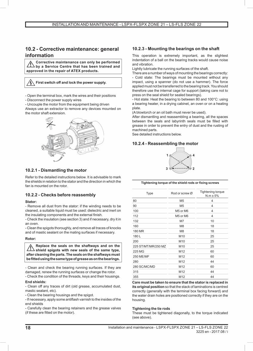
10.2.4 - Reassembling the motor
Tightening torque of the shield rods or fixing screws
Type Rod or screw Ø Tightening torque N.m ± 5%
80 M5 490 M5 4100 M5 or M6 4112 M5 or M6 4132 M7 10160 M8 18180 MR M8 18180 L M10 25200 M10 25225 ST/MT/MR/250 MZ M10 25225 MG M12 60250 ME/MF M12 60280 M12 44280 SC/MC/MD M12 60315 M12 44355 M12 44
Care must be taken to ensure that the stator is replaced in its original position so that the stack of laminations is centred correctly (generally with the terminal box facing forward) and the water drain holes are positioned correctly if they are on the housing.
Tightening the tie rodsThese must be tightened diagonally, to the torque indicated (see above).
1 4
3 2
INSTALLATION AND MAINTENANCE - LSPX-FLSPX ZONE 21 – LS-FLS ZONE 22

19
Installation and maintenance - LSPX-FLSPX ZONE 21 – LS-FLS ZONE 223225 en - 2017.08 / i
10.2.5 - Reassembling the terminal boxReconnect all the power supply wires in accordance with the diagram or markings made before dismantling. For terminal boxes equipped with a horn (part no. 89 on the exploded views) and/or a cable gland support plate, ensure that the seals have been correctly positioned before closing. Check that the terminal box components are tightened correctly.Note: It is advisable to test the motor at no load- If necessary, repaint the motor.- Mount the transmission device on the motor shaft extension and reinstall the motor on the machine to be driven (see section 4.3).
10.3 - Safety regulationsBefore any work is carried out on the motor or in the cabinet, ensure that the equipment is no longer
powered up (check the voltage at the power and auxiliary terminals, if necessary).
Before any work is carried out on the motor or in the cabinet, check that the cosine j compensation
capacitors are isolated and/or discharged (read the voltage at the terminals).
Before any work is carried out in the terminal box or in the cabinet, check that the space heaters are
switched off.
Depending on the type of thermal protection, the motor may remain switched on. Ensure that the
mains supply is disconnected before any work is carried out in the terminal box or in the cabinet.
10.4 - Routine maintenanceInspection after commissioningAfter approximately 50 hours’ operation, check the tightness of the screws fixing the motor and the coupling device. In the case of chain or belt transmission, check that the tension is correctly adjusted.CleaningTo ensure the motor operates correctly, remove any dust or foreign bodies which may clog the air intake and the housing fins.Precaution: Check that the motor is completely sealed (terminal box, drain holes, etc) before carrying out any cleaning operation.Dry cleaning (vacuuming or compressed air) is always preferable to wet cleaning.When cleaning the motor, be careful to avoid any built-up of static.
Cleaning must always be carried out at a pressure of less than 10 bars, from the centre of the motor
outwards to avoid dust and particles getting under the seals.
Draining condensation waterVariations in temperature cause condensation to form inside the motor. This must be removed before it affects the operation of the motor.
Condensation drain holes, located at the bottom of the motors (bearing in mind their operating position) are sealed with plugs which must be removed and then replaced every six months.Note: If there is high humidity and significant variations in temperature, or a prolonged stoppage, a shorter period is recommended.
Replace the drain hole covers to ensure that the motor conforms to the IP protection specified on
the nameplate. Replace the seals which have been removed with new seals of the same type. Clean the holes and plugs before reassembly.
10.4.1 - Greasing10.4.1.1 - Permanently greased bearingsFor all (F)LSPX motors of type 180 or below, the specified bearings provide a long grease life and therefore greasing for the lifetime of the machines. The grease life according to speed of rotation and ambient temperature is shown on the chart below.
10.4.1.2 - Bearings with grease nipplesThe bearings are lubricated in the factory.
Instructions for bearing maintenance are given on the nameplates on these machines.
For (F)LSPX motors of type 200 or above, the end shields are fitted with bearings lubricated by greases such as Técalémit-Hydraulic M8 x 125.
The frequency of lubrication and quantity and quality of grease are indicated on the nameplates.
Refer to these to ensure correct lubrication of the bearings.
Even in the event of prolonged storage or downtime, the interval between two greasing operations
should never exceed 2 years.
10
0
20
30
40
50
60
Amb T (°C)
3010 20
N = 750 min -1
N = 1500 min -1
N = 1000 min -1
5 15 25
N = 3000 min -1
Life in 000's of hours
INSTALLATION AND MAINTENANCE - LSPX-FLSPX ZONE 21 – LS-FLS ZONE 22
20
Installation and maintenance - LSPX-FLSPX ZONE 21 – LS-FLS ZONE 223225 en - 2017.08 / i
10.5 - Bearing maintenance10.5.1 - Checking the bearingsAs soon as you detect any of the following on the motor:- Abnormal noise or vibration- Abnormal temperature rise in the bearing even though it has been lubricated correctlythe condition of the bearings must be checked.Damaged bearings must be replaced as soon as possible to prevent worse damage to the motor and the equipment being driven.When one bearing needs to be replaced, the other bearing must also be replaced.The free bearing must allow the rotor shaft to expand (check its identification during dismantling).
10.5.2 - Reconditioning the bearingsBearings without grease nipplesDismantle the motor (see section 10.2.1); remove the old grease (if the bearings are not sealed) and clean the bearings and accessories with degreasing agent.Fill with new grease: the correct amount of new grease for the bearing is 50% of the free space.
Bearings with grease nipplesAlways begin by cleaning the waste grease channelIf using the type of grease stated on the nameplate, remove the covers and clean the grease nipple heads.If a different grease from that on the nameplate is being used, the motor must be dismantled and the bearings and accessories cleaned with degreasing agent (carefully clean the grease inlet and outlet pipes) to remove the old grease before relubrication.To ensure correct lubrication, fill the inner free spaces of the bearing retainers and flanges and 30% of the bearing free space.Then rotate the motor shaft to distribute the grease.
WarningAn excessive amount of grease causes excessive temperature rise in the bearing (statistically the number of bearings damaged by excessive grease is higher than the number of bearings damaged by insufficient lubrication).
Important noteThe new grease must be recently manufactured, of an equivalent performance level and must not contain any impurities (dust, water, etc).
10.6 - IP protection for the motorEach time the motor is dismantled and during planned site maintenance, replace the seals on the
shaftways, the shield spigots and the terminal box cover (if mastic) with new seals of the same type after cleaning all parts. The seals on the shaftways must be fitted using the same type of grease as on the bearings.
If the drain plugs are removed, they must be replaced in order to ensure that the motor conforms
to the IP protection specified on the nameplate. Replace the seals which have been removed with new seals of the same type. Clean the holes and plugs before reassembly.
If the terminal box cover is removed, clean all the parts and replace the seal with a new seal of the
same type, if its condition no longer provides the required degree of protection.
INSTALLATION AND MAINTENANCE - LSPX-FLSPX ZONE 21 – LS-FLS ZONE 22

21
Installation and maintenance - LSPX-FLSPX ZONE 21 – LS-FLS ZONE 223225 en - 2017.08 / i
10.7 - Troubleshooting guide
Incident Possible cause Remedy
Abnormal noise Originating in motor or machine being driven? Uncouple the motor from the equipment being drivenand test the motor on its own
Noisy motor Mechanical cause: if the noise persists afterswitching off the electrical power supply
- Vibration - Check that the key conforms to the type of balancing (see section 10.3)
- Damaged bearings - Change the bearings
- Mechanical friction: ventilation, coupling
- Check
Electrical cause: if the noise stops after switching off the power supply
- Check the power supply at the motor terminals
- Normal voltage and 3 phases balanced - Check the connection of the terminal block and the tightening of the connectors
- Abnormal voltage - Check the power supply line
- Phase imbalance (current) - Check the winding resistance and the balancing of the mains supply (voltage)
Motor heats up abnormally - Faulty ventilation - Check the environment- Clean the fan cover and the cooling fins- Check that the fan is correctly mounted on the shaft
- Faulty supply voltage - Check
- Terminal connection fault - Check
- Overload - Check the current consumption in relation to that indicated on the motor nameplate
- Partial short-circuit - Check the electrical continuity of the windings and/or the installation
- Phase imbalance - Check the winding resistance
Motor does not start No load- Mechanical seizing- Broken power supply line
When switched off:- Check by hand that the shaft rotates freely- Check the fuses, electrical protection, starting device, electrical continuity
On load- Phase imbalance
When switched off:- Check the direction of rotation (phase order)- Check the resistance and continuityof the windings- Check the electrical protection
INSTALLATION AND MAINTENANCE - LSPX-FLSPX ZONE 21 – LS-FLS ZONE 22

22
Installation and maintenance - LSPX-FLSPX ZONE 21 – LS-FLS ZONE 223225 en - 2017.08 / i
11 - LSPX MOTORS11.1 - LSPX 63 to LSPX 160 MP/LR motors11.1.1 - Dismantling- Remove the screws (27) and then take off the cover (13).- Pull out the fan (7) using a hub remover or two levers (for example, two screwdrivers) diametrically opposed to one another, using the shield (6) for support.- Remove the tie rods (14).- Remove the key (21).- Using a wooden mallet, tap the shaft on the fan side in order to loosen the drive end shield (5).- Remove the rotor shaft (3) and the DE shield (5) taking care not to knock the winding.- Remove the shield on the fan side (6).- Take out the preloading washer (59) and the seal of the NDE shield (54) for LS 100, 112 and 132 motors.- Remove the circlip (60) from flanged motors using angled circlip pliers.- Separate the DE shield from the rotor shaft.- The shaft can then be seen with its 2 bearings and, if appropriate, the circlip.Use a bearing remover to take out the bearings, taking care not to knock the running surfaces of the shaft.
11.1.2 - Reassembling motors without circlip- Mount the bearings on the rotor shaft.- Insert the rotor into the stator taking all possible precautions not to knock the winding.- Mount the DE shield (5).- For LSPX 63, 71 motors, mount the seal (39) with grease beforehand. - Place the preloading washer (59) in the bearing housing, then mount the NDE shield (6).- Place the tie rods (14) in position and tighten the nuts diagonally to the recommended torque (see section 10.2.4).- Mount the shield seals (39, 54, 308) with grease.- Mount the fan (7) using a drift to bed it into position.- Check that the motor turns freely by hand and that there is no radial play.- Replace the cover (13) and fix it with the screws (27).
11.1.3 - Reassembling motors with flange and circlip- Mount the DE bearing (30) in the flange (5) using the outer slip-ring for support.- Fit the circlip (60).- Mount this assembly on the rotor (3) using the inner slip-ring for support.- Mount the NDE bearing on the rotor.- Insert the rotor (3) and shield (5) assembly in the stator taking care not to knock the winding.- Place the preloading washer (59) in the bearing housing, then mount the NDE shield (6).- Place the tie rods (14) in position and tighten the nuts diagonally to the recommended torque (see section 10.2.4).- Mount the shield seals (39, 54, 308) with grease.- Mount the fan (7) using a drift to bed it into position.- Check that the motor turns freely by hand and that there is no axial play.- Replace the cover (13) and fix it with the screws (27).- Replace the key (21).
6 5
397
59
50 30
AR AV AR AV
6 5
39307
59 60
50
LSPX 63 - LSPX 71foot mounted
LSPX 63 - LSPX 71flange mounted (or foot and flange)
AR AV AR AV
59 56
3087 50 30
6 5
3950 307
59 60
LSPX 80 - LSPX 90foot mounted
LSPX 80 - LSPX 90flange mounted (or foot and flange)
AR AV AR AV
6 5
30854
59
50 30
6 5
3950 3054
59 60
LSPX 100 - LSPX 112 - LSPX 132foot mounted
LSPX 100 - LSPX 112 - LSPX 132flange mounted (or foot and flange)
AR AV AR AV
6 5
3950 3054
59 60
54
5
50
6 59
3930
LSPX 160 MP/LRfoot mounted
LSPX 160 MP/LRflange mounted (or foot and flange)
INSTALLATION AND MAINTENANCE - LSPX-FLSPX ZONE 21 – LS-FLS ZONE 22

23
Installation and maintenance - LSPX-FLSPX ZONE 21 – LS-FLS ZONE 223225 en - 2017.08 / i
LSPX 63 to LSPX 160 MP/LR
71 b
98
213
5
22
5
5
308
23
IM B3
IM B14
IM B5
13
7
2514855468426 2
160
5950
27
30
39
39
78
LSPX 63 to LSPX 160 MP/LRRef. Description Ref. Description Ref. Description
1 Wound stator 22 Shaft extension washer 59 Preloading (wavy) washer
2 Housing 23 Shaft extension screw 60 Circlip
3 Rotor 25 Lifting ring 71 b Metal terminal box
5 DE shield 26 Nameplate 78 Cable gland
6 NDE shield 27 Fan cover screw 84 Terminal block
7 Fan 30 DE bearing 85 Set screw
13 Fan cover 39 Drive end seal 98 Connectors
14 Tie rods 50 Non drive end bearing 308 Labyrinth seal
21 Shaft extension key 54 NDE seal
INSTALLATION AND MAINTENANCE - LSPX-FLSPX ZONE 21 – LS-FLS ZONE 22

24
Installation and maintenance - LSPX3225 en - 2017.08 / i
11.2 - LSPX 160 M/L, LSPX 180 MT/LR motors11.2.1 - Dismantling- Remove the screws (27) and then take off the cover (13).- Pull out the fan (7) using a hub remover or 2 levers diametrically opposite one another, using the shield (6) for support.- Take out the key (21) and remove the seals (39 and 54) for foot mounted motors, (39) for flange mounted motors.- Unscrew the tie rods (14) then remove them.- Unscrew the fixing screws (40) on the inner bearing retainer (33).- Using a bronze drift, remove the shields (5 and 6) by tapping gently on the shield bosses. Take out the preloading washer (59).- Remove the circlip (38) if necessary (flange mounted motor).- Remove the rotor (3) from the stator (1) taking care not to touch the winding.- Take out the bearings (30) and (50) using a bearing remover, while protecting the end of the shaft extension with a washer. Avoid knocking the running surfaces of the shaft.
11.2.2 - Reassembly- See section 10.2.4 before reassembly.- Insert the inner bearing retainer (33) at the drive end of the rotor then fit new bearings on the shaft.- Mount the circlip (38) for flange mounted motors.- Insert the rotor (3) in the stator (1) taking care not to knock the winding.- Position the preloading washer (59) with a small amount of grease in the back of the bearing cage of the NDE shield (6), then remount the NDE shield (6), positioning it on the stator.- To fit the bearing retainer (33), screw a threaded rod with the same diameter as the screws (40) into one of the tapped holes of the bearing retainer to maintain its angular position when refitting the DE shield (5). When there is a flange, mount a new seal (39) with the spring facing outwards.- Remount the DE shield (5) taking care to allow for the positioning of a bearing retainer if used.- Place the tie rods (14) in position and tighten the nuts diagonally to the recommended torque (see section 10.2.4).- Fix the bearing retainer with its screws (33).- Mount the new shield seals with grease (54) at the non drive end, (39) at the drive end for foot mounted motors.- Mount the fan (7) using a drift to bed it into position.- Check that the rotor turns freely by hand (that there is no axial play if there is a locked end shield). - Replace the cover (13) and fix it with the screws (27).- Replace the key (21).
The shields must be fitted with a DE inner bearing retainer.
AR AV AR AV
LSPX 160 M/L - LSPX 180 MT/LRfoot mounted
standard bearings
LSPX 160 M/L - LSPX 180 MT/LRflange mounted (or foot and flange)
standard bearings
LSPX 160 M/L, LSPX 180 MT/LR
1327
754
14
65950
7470
3
21
39
5
301
3833
26
2
40
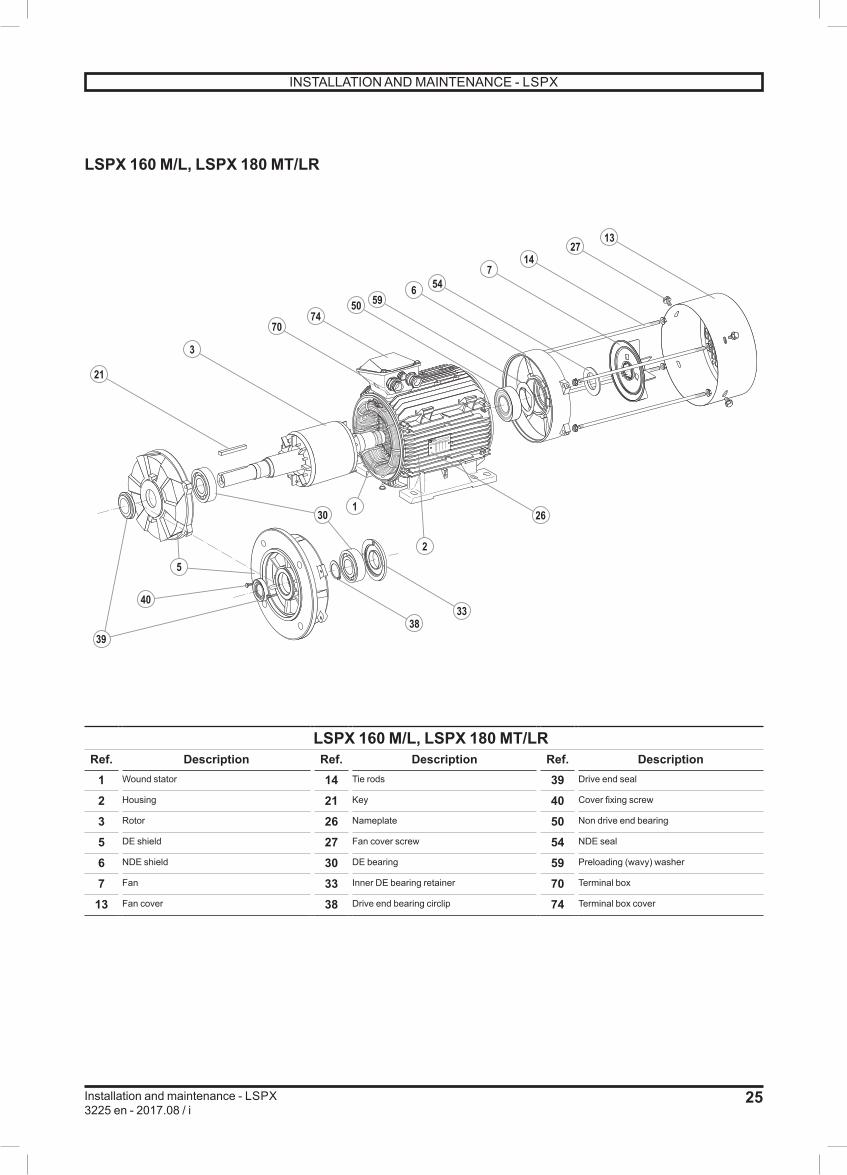
LSPX 160 M/L, LSPX 180 MT/LRRef. Description Ref. Description Ref. Description
1 Wound stator 14 Tie rods 39 Drive end seal
2 Housing 21 Key 40 Cover fixing screw
3 Rotor 26 Nameplate 50 Non drive end bearing
5 DE shield 27 Fan cover screw 54 NDE seal
6 NDE shield 30 DE bearing 59 Preloading (wavy) washer
7 Fan 33 Inner DE bearing retainer 70 Terminal box
13 Fan cover 38 Drive end bearing circlip 74 Terminal box cover
AR AV AR AV
LSPX 160 M/L - LSPX 180 MT/LRfoot mounted
drive end roller bearings
LSPX 160 M/L - LSPX 180 MT/LRflange mounted (or foot and flange)
drive end roller bearings
INSTALLATION AND MAINTENANCE - LSPX
25
Installation and maintenance - LSPX3225 en - 2017.08 / i
LSPX 160 M/L, LSPX 180 MT/LR
1327
754
14
65950
7470
3
21
39
5
301
3833
26
2
40
LSPX 160 M/L, LSPX 180 MT/LRRef. Description Ref. Description Ref. Description
1 Wound stator 14 Tie rods 39 Drive end seal
2 Housing 21 Key 40 Cover fixing screw
3 Rotor 26 Nameplate 50 Non drive end bearing
5 DE shield 27 Fan cover screw 54 NDE seal
6 NDE shield 30 DE bearing 59 Preloading (wavy) washer
7 Fan 33 Inner DE bearing retainer 70 Terminal box
13 Fan cover 38 Drive end bearing circlip 74 Terminal box cover
AR AV AR AV
LSPX 160 M/L - LSPX 180 MT/LRfoot mounted
drive end roller bearings
LSPX 160 M/L - LSPX 180 MT/LRflange mounted (or foot and flange)
drive end roller bearings
INSTALLATION AND MAINTENANCE - LSPX
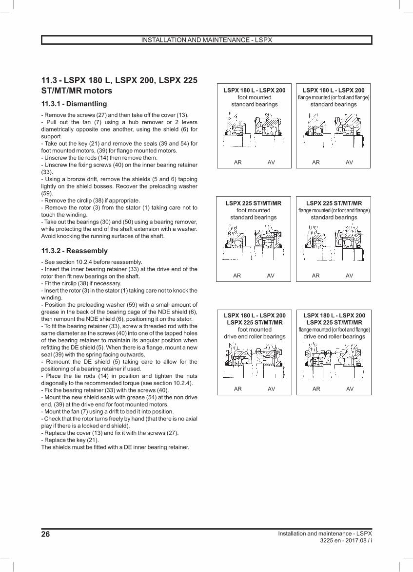
26
Installation and maintenance - LSPX3225 en - 2017.08 / i
11.3 - LSPX 180 L, LSPX 200, LSPX 225 ST/MT/MR motors11.3.1 - Dismantling- Remove the screws (27) and then take off the cover (13).- Pull out the fan (7) using a hub remover or 2 levers diametrically opposite one another, using the shield (6) for support.- Take out the key (21) and remove the seals (39 and 54) for foot mounted motors, (39) for flange mounted motors. - Unscrew the tie rods (14) then remove them.- Unscrew the fixing screws (40) on the inner bearing retainer (33).- Using a bronze drift, remove the shields (5 and 6) tapping lightly on the shield bosses. Recover the preloading washer (59).- Remove the circlip (38) if appropriate.- Remove the rotor (3) from the stator (1) taking care not to touch the winding.- Take out the bearings (30) and (50) using a bearing remover, while protecting the end of the shaft extension with a washer. Avoid knocking the running surfaces of the shaft.
11.3.2 - Reassembly- See section 10.2.4 before reassembly.- Insert the inner bearing retainer (33) at the drive end of the rotor then fit new bearings on the shaft.- Fit the circlip (38) if necessary.- Insert the rotor (3) in the stator (1) taking care not to knock the winding.- Position the preloading washer (59) with a small amount of grease in the back of the bearing cage of the NDE shield (6), then remount the NDE shield (6), positioning it on the stator.- To fit the bearing retainer (33), screw a threaded rod with the same diameter as the screws (40) into one of the tapped holes of the bearing retainer to maintain its angular position when refitting the DE shield (5). When there is a flange, mount a new seal (39) with the spring facing outwards.- Remount the DE shield (5) taking care to allow for the positioning of a bearing retainer if used.- Place the tie rods (14) in position and tighten the nuts diagonally to the recommended torque (see section 10.2.4).- Fix the bearing retainer (33) with the screws (40).- Mount the new shield seals with grease (54) at the non drive end, (39) at the drive end for foot mounted motors.- Mount the fan (7) using a drift to bed it into position.- Check that the rotor turns freely by hand (that there is no axial play if there is a locked end shield). - Replace the cover (13) and fix it with the screws (27).- Replace the key (21).The shields must be fitted with a DE inner bearing retainer.
AR AV AR AV
LSPX 180 L - LSPX 200 foot mounted
standard bearings
LSPX 180 L - LSPX 200 flange mounted (or foot and flange)
standard bearings
AR AV AR AV
LSPX 225 ST/MT/MRfoot mounted
standard bearings
LSPX 225 ST/MT/MRflange mounted (or foot and flange)
standard bearings
AR AV AR AV
LSPX 180 L - LSPX 200 LSPX 225 ST/MT/MR
foot mounteddrive end roller bearings
LSPX 180 L - LSPX 200 LSPX 225 ST/MT/MR
flange mounted (or foot and flange)drive end roller bearings
INSTALLATION AND MAINTENANCE - LSPX
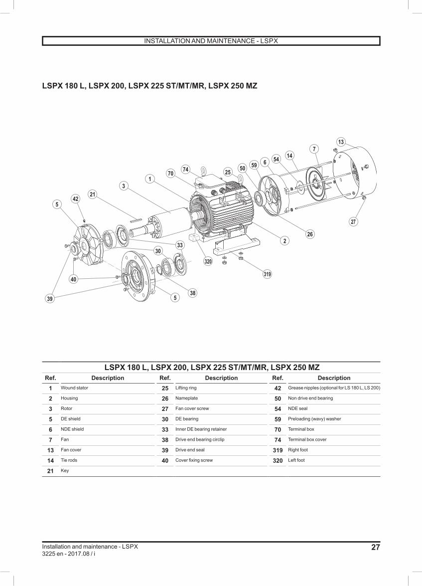
27
Installation and maintenance - LSPX3225 en - 2017.08 / i
LSPX 180 L, LSPX 200, LSPX 225 ST/MT/MR, LSPX 250 MZ
5
39 538
3033
320
319
262
213
170 74 25
13
50 59 6 54 147
42
27
40
LSPX 180 L, LSPX 200, LSPX 225 ST/MT/MR, LSPX 250 MZRef. Description Ref. Description Ref. Description
1 Wound stator 25 Lifting ring 42 Grease nipples (optional for LS 180 L, LS 200)
2 Housing 26 Nameplate 50 Non drive end bearing
3 Rotor 27 Fan cover screw 54 NDE seal
5 DE shield 30 DE bearing 59 Preloading (wavy) washer
6 NDE shield 33 Inner DE bearing retainer 70 Terminal box
7 Fan 38 Drive end bearing circlip 74 Terminal box cover
13 Fan cover 39 Drive end seal 319 Right foot
14 Tie rods 40 Cover fixing screw 320 Left foot
21 Key
INSTALLATION AND MAINTENANCE - LSPX

28
Installation and maintenance - LSPX3225 en - 2017.08 / i
11.4 - LSPX 225 MG, LSPX 250 ME/MF, LSPX 280 SC/MC/MD motors11.4.1 - Dismantling the NDE shield- Remove the fixing screws (27) and then take off the cover (13).- Take out the fan (7).- Remove the fixing screws (62) from the inner NDE bearing retainer (53).- Remove the fixing screws (273) from the NDE shield (6).- Using two levers or a flexible hammer, disengage the NDE shield (6) taking care not to place it aslant.Remove the shield by sliding it along the shaft. The seal (54) follows behind and is no longer usable.- Put the dismantled components to one side and recover the preloading washer (59), which should be replaced in its housing.
11.4.2 - Dismantling the DE shield- Dismantle the DE shield without removing the rotor (3). To do this:- Remove the fixing screws (40) from the inner DE bearing retainer (33).- Remove the fixing screws (270) from the DE shield (5).- Take out the key (21).- Using two levers or a flexible hammer, disengage the DE shield (5) taking care not to place it aslant. - Remove the shield by sliding it along the shaft. The seal (39) follows behind and is no longer usable.
11.4.3 - Changing the antifriction bearings- Using an appropriate lifting tool, take out the rotor without knocking the winding.- Remove the bearings (30) and (50) with an appropriate tool, protecting the end of the shaft extension. Avoid knocking the running surfaces of the shaft. - Change the bearings, following the instructions given under General information in section 10.2.3.
IMPORTANT: Before undertaking any of these procedures, read section 10.2.2 "CHECKS BEFORE REASSEMBLY".
11.4.4 - Reassembly- Mount the DE bearing (30) on the rotor shaft (take care not to forget the inner DE bearing retainer (33) and the circlip (38), and also the NDE bearing (50) if and only if the internal Ø of the stator allows the inner NDE bearing retainer (53) to pass through.- Insert the rotor into the stator taking care not to knock the winding. Install the NDE bearing if this has not already been done, as well as the circlip (60).- Fill with new grease: the correct amount of new grease for the bearing is 50% of the free space.- Position the shields. Begin with the DE shield (5). Fix a dowel pin in one of the inner bearing retainer (33) tapped holes so that the grease inlet pipes fully correspond.- Position the preloading washer (59) with a small amount of grease in the back of the bearing cage of the NDE shield (6). Fix a dowel pin in one of the inner bearing retainer (53) tapped holes so that the grease inlet pipes fully correspond.
From now on, we recommend checking at every step that the rotor turns freely by hand before continuing to the next instruction.- Replace the shield fixing screws (270) and (273) in position and tighten the nuts diagonally up to the recommended torque (see section 10.2.4).- Replace the fixing screws (40) and (62) on the inner bearing retainers (33) and (53).- Grease and install a new seal (54).- Replace the fan (7).- Grease and install a new seal (39).- Replace the cover (13) and reinsert the fixing screws (27).- Replace the key (21).
The shields must be fitted with an inner bearing retainer.
AR AV AR AV
LSPX 225 MG, LSPX 250 ME/MF, LSPX 280 SC/MC/MD
standard bearings
LSPX 225 MG, LSPX 250 ME/MF, LSPX 280 SC/MC/MD
drive end roller bearings
INSTALLATION AND MAINTENANCE - LSPX

29
Installation and maintenance - LSPX3225 en - 2017.08 / i
LSPX 225 MG, LSPX 250 ME/MF, LSPX 280 SC/MC/MD
15
270
3
1327
21
5059 42
60
54
53
7074
3033
3842
2
662
2737
40
39
LSPX 225 MG, LSPX 250 ME/MF, LSPX 280 SC/MC/MDRef. Description Ref. Description Ref. Description
1 Wound stator 30 DE bearing 54 NDE seal
2 Housing 33 Inner DE bearing retainer 59 Preloading (wavy) washer
3 Rotor 38 Drive end bearing circlip 60 Non drive end bearing circlip
5 DE shield 39 Drive end seal 62 Cover fixing screw
6 NDE shield 40 Cover fixing screw 70 Terminal box
7 Fan 42 Grease nipples 74 Terminal box cover
13 Fan cover 50 Non drive end bearing 270 DE shield fixing screw
21 Shaft extension key 53 Inner NDE bearing retainer 273 NDE shield fixing screw
27 Fan cover screw
INSTALLATION AND MAINTENANCE - LSPX

30
Installation and maintenance - LSPX3225 en - 2017.08 / i
12 - FLSPX MOTORS12.1 - FLSPX 80 to FLSPX 132 motors12.1.1 - Dismantling- Remove the screws (27) and then take off the cover (13).- Pull out the fan (7) using a hub remover or two levers (for example, two screwdrivers) diametrically opposed to one another, using the shield (6) for support.- Remove the tie rods (14).- Remove the key (21).- Using a wooden mallet, tap the shaft on the fan side in order to loosen the drive end shield (5).- Remove the rotor shaft (3) and the DE shield (5) taking care not to knock the winding.- Remove the shield on the fan side (6).- Take out the preloading washer (59).- Remove the circlip (60) from flanged motors using angled circlip pliers.- Separate the DE shield from the rotor shaft.- The shaft can then be seen with its 2 bearings and, if appropriate, the circlip.Use a bearing remover to take out the bearings, taking care not to knock the running surfaces of the shaft.- On each shield, remove all traces of mastic sealant on the housing spigot.
12.1.2 - Reassembling motors without circlip- Each shield must be mounted with a continuous line of silicon or polyurethane mastic on the housing spigot.- Mount the bearings on the rotor shaft.- Insert the rotor into the stator taking all possible precautions not to knock the winding.- Mount the DE shield (5).- Place the preloading washer (59) in the bearing housing, then mount the NDE shield (6).- Place the tie rods (14) in position and tighten the nuts diagonally to the recommended torque (see section 10.2.4).- Mount the new shield seals (39 and 54) with grease.- Mount the fan (7) using a drift to bed it into position.- Check that the motor turns freely by hand and that there is no radial play.- Replace the cover (13) and fix it with the screws (27).- Replace the key (21).
12.1.3 - Reassembling motors with flange and circlip- Each shield must be mounted with a continuous line of silicon or polyurethane mastic on the housing spigot.- Mount the DE bearing (30) in the flange (5) using the outer slip-ring for support.- Fit the circlip (60).- Mount this assembly on the rotor (3) using the inner slip-ring for support.- Mount the NDE bearing on the rotor.- Insert the rotor (3) and shield (5) assembly in the stator taking care not to knock the winding.- Place the preloading washer (59) in the bearing housing, then mount the NDE shield (6).
- Place the tie rods (14) in position and tighten the nuts diagonally to the recommended torque (see section 10.2.4).- Mount the new shield seals (39 and 54) with grease.- Mount the fan (7) using a drift to bed it into position.- Check that the motor turns freely by hand and that there is no axial play.- Replace the cover (13) and fix it with the screws (27).- Replace the key (21).
56 59 56 59
54 50 503930 3054 39
60
FLSPX 80 to 132foot mounted
NDE DE
FLSPX 80 to 132flange mounted (or foot and flange)
NDE DE
INSTALLATION AND MAINTENANCE - LSPX

31
Installation and maintenance - LSPX3225 en - 2017.08 / i
FLSPX 80 to 132
71
21
3
5
22
5
5
39
23 IM B3
IM B14
IM B5
13
27
14
7
54
684
262
1
60
5950
30
39
26
78
39
84
FLSPX 80 to FLSPX 132Ref. Description Ref. Description Ref. Description
1 Wound stator 21 Shaft extension key 54 NDE seal
2 Housing 22 Shaft extension washer 59 Preloading (wavy) washer
3 Rotor 23 Shaft extension screw 60 Circlip
5 DE shield 26 Nameplate 71 Terminal box
6 NDE shield 27 Fan cover screw 78 Cable gland
7 Fan 30 DE bearing 84 Terminal block
13 Fan cover 39 Drive end seal
14 Tie rods 50 Non drive end bearing
INSTALLATION AND MAINTENANCE - LSPX

32
Installation and maintenance - FLSPX3225 en - 2017.08 / i
12.2 - FLSPX 160 and 180 motors12.2.1 - Dismantling the NDE shield- Remove the fixing screws (27) and then take off the cover (13).- Take out the fan (7).- Remove the fixing screws (273) from the NDE shield (6).- Using two levers or a flexible hammer, disengage the NDE shield (6) taking care not to place it aslant.Remove the shield by sliding it along the shaft. The seal (54) follows behind and is no longer usable.- Recover the preloading washer (59) which should be replaced in its housing.- Remove all traces of mastic sealant on the housing spigot.
12.2.2 - Dismantling the DE shield- Remove the fixing screws (270) from the DE shield.- Using an appropriate lifting tool, take out the rotor (3) + DE shield (5) assembly, without knocking the winding.- Remove the fixing screws (40) from the inner DE bearing retainer (33).- Take out the key (21).- Using two levers or a flexible hammer, disengage the DE shield (5) from the rotor (3) taking care not to place it aslant.- Remove the shield by sliding it along the shaft. The seal(s) (39 or 39a and 39b in the case of roller bearings) follow(s) behind and is (are) no longer usable.- Remove all traces of mastic sealant on the housing spigot.
12.2.3 - Changing the antifriction bearings- Remove the bearings (30) and (50) with an appropriate tool, protecting the end of the shaft extension. Avoid knocking the running surfaces of the shaft.- Change the bearings in accordance with the instructions described under General information in section 10.2 (shrink-fitting only).IMPORTANT: Before undertaking any of these procedures, read the "CHECKS BEFORE REASSEMBLY" section.
12.2.4 - Reassembly- Each shield must be mounted with a continuous line of silicon or polyurethane mastic on the housing spigot.- Mount the bearings on the rotor shaft, taking care not to forget the inner DE bearing retainer (33) and outer DE bearing retainer (53) in the case of roller bearings.- In the case of a shield fitted with roller bearings, position and grease the internal seal (39b) before mounting the shield (5). The lip of the seal should be facing the outside of the shield.- Slide the DE shield (5) onto the bearing (30).- Replace the fixing screws (40) on the inner DE bearing retainer (33) or outer DE bearing retainer (53) in the case of roller bearings. Replace the AZ sealing washers to ensure a perfect seal.- Insert the rotor + shield assembly in the stator without knocking the winding.- Place the shields, grease nipples facing upwards, not forgetting the preloading washer (59) at the non drive end. Slide them into position.- Fit the shields firmly in place.- Check that the rotor turns freely by hand.
From now on, we recommend checking at every step that the rotor turns freely by hand before continuing to the next instruction.- Replace the shield fixing screws (270) and (273) in position and tighten them diagonally up to the recommended torque (see section 10.2.4).- Grease a new seal (54) and replace with a drift.- Replace the fan (7).- Replace the cover (13) and reinsert the fixing screws (27).- Grease the new seal (39 or 39a) and replace with a drift.- Lubricate the roller bearings, turning the shaft by hand.Amount of grease for roller bearings:- Frame size 160: DE = 40 cm3
- Frame size 180: DE = 50 cm3
56 59
50 3054 39
33 56 59
50 3054 39
33
56 53
50 39a39b 39b 39a3054
33 56 53
50 3054
33
56 59
50 3054 39
33 60
38 60
60
38
FLSPX 160 and 180foot mounted (except V6)
standard bearings
NDE DE
FLSPX 160 and 180foot mounted IM V6standard bearings
NDE DE
FLSPX 160 and 180foot mounted IM V6
drive end roller bearings
NDE DE
FLSPX 160 and 180flange mounted (or foot and flange)
drive end roller bearings
NDE DE
FLSPX 160 and 180flange mounted (or foot and flange)
standard bearings
NDE DE
INSTALLATION AND MAINTENANCE - FLSPX
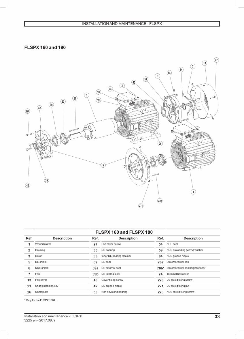
33
Installation and maintenance - FLSPX3225 en - 2017.08 / i
FLSPX 160 and 180
270
59
4230
3321
50
40
27
39
271270
273
6454
713
5
3
1
26
6
70a
70b
742
FLSPX 160 and FLSPX 180Ref. Description Ref. Description Ref. Description
1 Wound stator 27 Fan cover screw 54 NDE seal
2 Housing 30 DE bearing 59 NDE preloading (wavy) washer
3 Rotor 33 Inner DE bearing retainer 64 NDE grease nipple
5 DE shield 39 DE seal 70a Stator terminal box
6 NDE shield 39a DE external seal 70b* Stator terminal box height spacer
7 Fan 39b DE internal seal 74 Terminal box cover
13 Fan cover 40 Cover fixing screw 270 DE shield fixing screw
21 Shaft extension key 42 DE grease nipple 271 DE shield fixing nut
26 Nameplate 50 Non drive end bearing 273 NDE shield fixing screw
* Only for the FLSPX 180 L
INSTALLATION AND MAINTENANCE - FLSPX
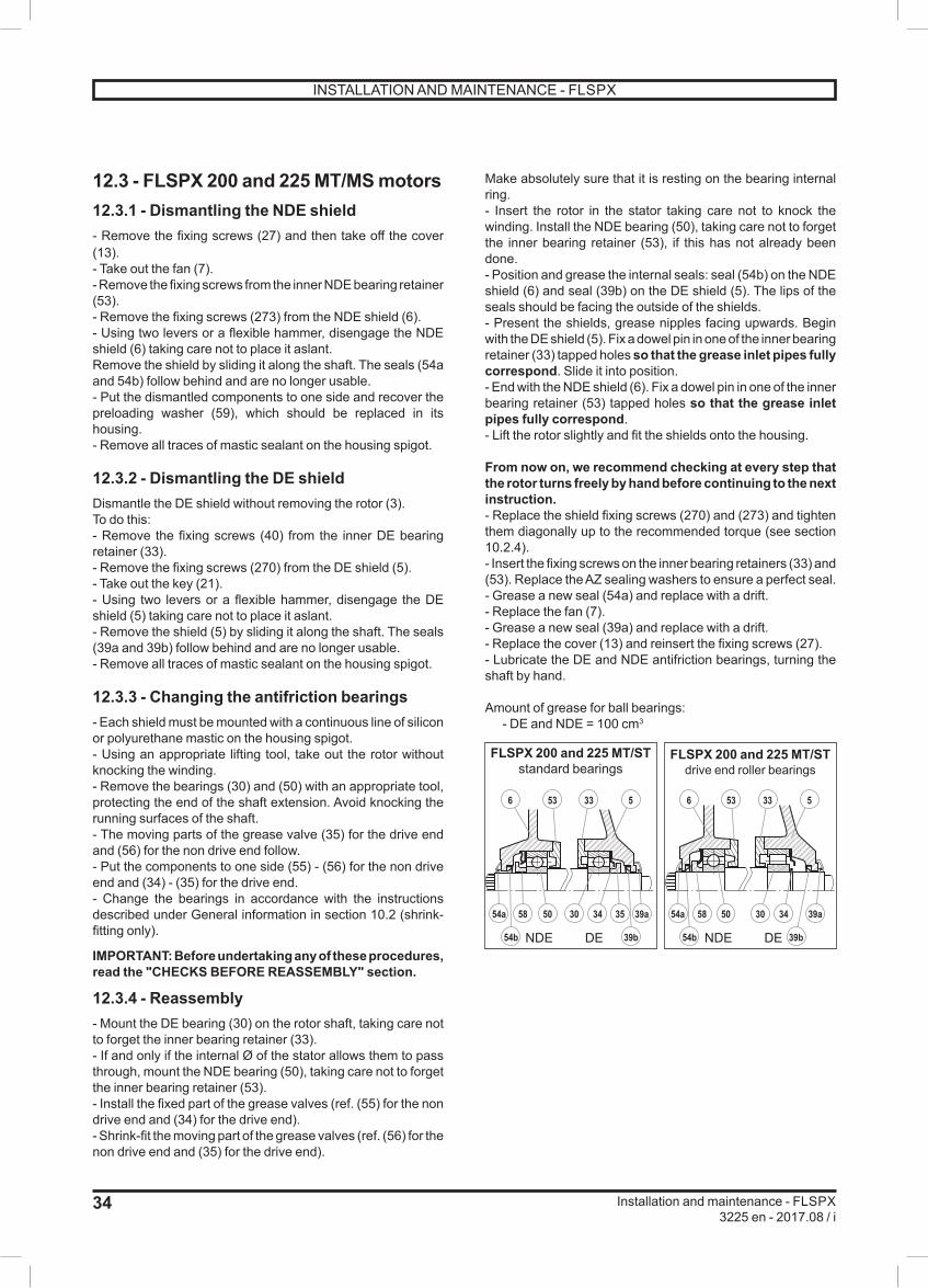
34
Installation and maintenance - FLSPX3225 en - 2017.08 / i
12.3 - FLSPX 200 and 225 MT/MS motors12.3.1 - Dismantling the NDE shield- Remove the fixing screws (27) and then take off the cover (13).- Take out the fan (7).- Remove the fixing screws from the inner NDE bearing retainer (53).- Remove the fixing screws (273) from the NDE shield (6).- Using two levers or a flexible hammer, disengage the NDE shield (6) taking care not to place it aslant.Remove the shield by sliding it along the shaft. The seals (54a and 54b) follow behind and are no longer usable.- Put the dismantled components to one side and recover the preloading washer (59), which should be replaced in its housing.- Remove all traces of mastic sealant on the housing spigot.
12.3.2 - Dismantling the DE shieldDismantle the DE shield without removing the rotor (3).To do this:- Remove the fixing screws (40) from the inner DE bearing retainer (33).- Remove the fixing screws (270) from the DE shield (5).- Take out the key (21).- Using two levers or a flexible hammer, disengage the DE shield (5) taking care not to place it aslant.- Remove the shield (5) by sliding it along the shaft. The seals (39a and 39b) follow behind and are no longer usable.- Remove all traces of mastic sealant on the housing spigot.
12.3.3 - Changing the antifriction bearings- Each shield must be mounted with a continuous line of silicon or polyurethane mastic on the housing spigot.- Using an appropriate lifting tool, take out the rotor without knocking the winding.- Remove the bearings (30) and (50) with an appropriate tool, protecting the end of the shaft extension. Avoid knocking the running surfaces of the shaft.- The moving parts of the grease valve (35) for the drive end and (56) for the non drive end follow.- Put the components to one side (55) - (56) for the non drive end and (34) - (35) for the drive end.- Change the bearings in accordance with the instructions described under General information in section 10.2 (shrink-fitting only).
IMPORTANT: Before undertaking any of these procedures, read the "CHECKS BEFORE REASSEMBLY" section.
12.3.4 - Reassembly- Mount the DE bearing (30) on the rotor shaft, taking care not to forget the inner bearing retainer (33).- If and only if the internal Ø of the stator allows them to pass through, mount the NDE bearing (50), taking care not to forget the inner bearing retainer (53).- Install the fixed part of the grease valves (ref. (55) for the non drive end and (34) for the drive end).- Shrink-fit the moving part of the grease valves (ref. (56) for the non drive end and (35) for the drive end).
Make absolutely sure that it is resting on the bearing internal ring.- Insert the rotor in the stator taking care not to knock the winding. Install the NDE bearing (50), taking care not to forget the inner bearing retainer (53), if this has not already been done.- Position and grease the internal seals: seal (54b) on the NDE shield (6) and seal (39b) on the DE shield (5). The lips of the seals should be facing the outside of the shields.- Present the shields, grease nipples facing upwards. Begin with the DE shield (5). Fix a dowel pin in one of the inner bearing retainer (33) tapped holes so that the grease inlet pipes fully correspond. Slide it into position.- End with the NDE shield (6). Fix a dowel pin in one of the inner bearing retainer (53) tapped holes so that the grease inlet pipes fully correspond.- Lift the rotor slightly and fit the shields onto the housing.
From now on, we recommend checking at every step that the rotor turns freely by hand before continuing to the next instruction.- Replace the shield fixing screws (270) and (273) and tighten them diagonally up to the recommended torque (see section 10.2.4).- Insert the fixing screws on the inner bearing retainers (33) and (53). Replace the AZ sealing washers to ensure a perfect seal.- Grease a new seal (54a) and replace with a drift.- Replace the fan (7).- Grease a new seal (39a) and replace with a drift.- Replace the cover (13) and reinsert the fixing screws (27).- Lubricate the DE and NDE antifriction bearings, turning the shaft by hand.
Amount of grease for ball bearings: - DE and NDE = 100 cm3
39a35343054a
39b54b 39b54b
58 50
533536
39a343054a 58 50
533536
FLSPX 200 and 225 MT/STstandard bearings
NDE DE
FLSPX 200 and 225 MT/STdrive end roller bearings
NDE DE
INSTALLATION AND MAINTENANCE - FLSPX

35
Installation and maintenance - FLSPX3225 en - 2017.08 / i
FLSPX 200 and 225 MT/ST
27
4235
3430
3321
7074
253
5055
5956
64273
54b
54a
713
39b39a
40270
4065
406271
270
4566
5
3
26
261
FLSPX 200 and FLSPX 225 MT/STRef. Description Ref. Description Ref. Description
1 Wound stator 33 Inner DE bearing retainer 55 Fixed part of NDE grease valve
2 Housing 34 Fixed part of DE grease valve 56 Moving part of NDE grease valve
3 Rotor 35 Moving part of DE grease valve 59 NDE preloading (wavy) washer
5 DE shield 39a DE external seal 64 NDE grease nipple
6 NDE shield 39b DE internal seal 70 Stator terminal box
7 Fan 40 Cover fixing screw 74 Stator terminal box lid
13 Fan cover 42 DE grease nipple 270 DE shield fixing screw
21 Shaft extension key 50 Non drive end bearing 271 DE shield fixing nut
26 Nameplate 53 Inner NDE bearing retainer 273 NDE shield fixing screw
27 Fan cover screw 54a NDE external seal 406 DE grease valve cover plate
30 DE bearing 54b NDE internal seal 456 NDE grease valve cover plate
INSTALLATION AND MAINTENANCE - FLSPX

36
Installation and maintenance - FLSPX3225 en - 2017.08 / i
12.4 - FLSPX 225 M to 280 motors12.4.1 - Dismantling the NDE shield- Remove the fixing screws (27) and then take off the cover (13).- Remove the shaft extension screw if necessary.- Take out the fan (7).- Remove the fixing screws from the inner NDE bearing retainer (53).- Remove the fixing screws (273) from the NDE shield (6).- Remove the fan key if appropriate.- Using two levers or a flexible hammer, disengage the NDE shield (6) taking care not to place it aslant.Remove the shield by sliding it along the shaft. The seals (54a) and (54b) follow behind and are no longer usable.- Put the dismantled components to one side and recover the preloading washer (59), which should be replaced in its housing.- Remove all traces of mastic sealant on the housing spigot.
12.4.2 - Dismantling the DE shield- Dismantle the DE shield without removing the rotor (3). To do this:- Remove the fixing screws (40) from the inner DE bearing retainer (33).- Remove the fixing screws (270) from the DE shield (5).- Take out the key (21).- Using two levers or a flexible hammer, disengage the DE shield (5) taking care not to place it aslant.- Remove the shield by sliding it along the shaft. The seals (39a) and (39b) follow behind and are no longer usable.- Remove all traces of mastic sealant on the housing spigot.
12.4.3 - Changing the antifriction bearings- Using an appropriate lifting tool, take out the rotor without knocking the winding.- Take off the DE circlip (38).- Remove the bearings (30) and (50) with an appropriate tool, protecting the end of the shaft extension. Avoid knocking the running surfaces of the shaft.- Change the bearings in accordance with the instructions described under General information in section 10.2 (shrink-fitting only). IMPORTANT: Before undertaking any of these procedures, read the "CHECKS BEFORE REASSEMBLY" section.
12.4.4 - Reassembly- Each shield must be mounted with a continuous line of silicon or polyurethane mastic on the housing spigot.- Fill the decompression grooves (416) located in the shaftway with grease.- Mount the DE bearings (30) on the rotor shaft, taking care not to forget the inner bearing retainer (33) and the circlip (38).- If and only if the internal Ø of the stator allows them to pass through, mount the NDE bearing, taking care not to forget the inner bearing retainer (53).- Insert the rotor in the stator taking care not to knock the winding. Install the NDE bearing (50) and the inner bearing retainer (53), if this has not already been done.- Position and grease the internal seals: seal (54b) on the NDE shield (6) and seal (39b) on the DE shield (5). The lips of the seals should be facing the outside of the shields.
- Present the shields, grease nipples facing upwards. Begin with the DE shield (5). Fix a dowel pin in one of the inner bearing retainer (33) tapped holes so that the grease inlet pipes fully correspond.- End with the NDE shield (6). Fix a dowel pin in one of the inner bearing retainer (53) tapped holes so that the grease inlet pipes fully correspond.- Lift the rotor slightly and fit the shields in place.From now on, we recommend checking at every step that the rotor turns freely by hand before continuing to the next instruction.- Replace the shield fixing screws (270) and (273) and tighten them diagonally up to the recommended torque (see section 10.2.4).- Insert the fixing screws on the inner bearing retainers (33) and (53). Replace the AZ sealing washers to ensure a perfect seal.- Grease a new seal (54a) and replace with a drift.- Replace the fan key if appropriate.- Replace the fan (7).- Replace the shaft extension screw (10) and (11) if necessary.- Replace the cover (13) and reinsert the fixing screws (27).- Grease a new seal (39a) and replace with a drift.- Lubricate the DE and NDE antifriction bearings, turning the shaft by hand.Amount of grease for ball bearings: - Frame size 225-250: DE and NDE = 120 cm3
- Frame size 280: DE = 170 cm3/NDE = 120 cm3
3353
6
50
416
54a 54b
3353
6
50
416
54a 54b
30
39a
39b
5
38
5
38
30
39a
39b
FLSPX 225 M to 280standard bearings
FLSPX 225 M to 280drive end roller bearings
NDE DE
NDE DE
INSTALLATION AND MAINTENANCE - FLSPX
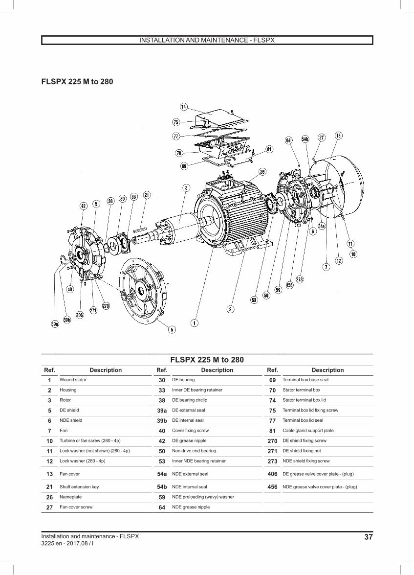
37
Installation and maintenance - FLSPX3225 en - 2017.08 / i
FLSPX 225 M to 280
FLSPX 225 M to 280Ref. Description Ref. Description Ref. Description
1 Wound stator 30 DE bearing 69 Terminal box base seal
2 Housing 33 Inner DE bearing retainer 70 Stator terminal box
3 Rotor 38 DE bearing circlip 74 Stator terminal box lid
5 DE shield 39a DE external seal 75 Terminal box lid fixing screw
6 NDE shield 39b DE internal seal 77 Terminal box lid seal
7 Fan 40 Cover fixing screw 81 Cable gland support plate
10 Turbine or fan screw (280 - 4p) 42 DE grease nipple 270 DE shield fixing screw
11 Lock washer (not shown) (280 - 4p) 50 Non drive end bearing 271 DE shield fixing nut
12 Lock washer (280 - 4p) 53 Inner NDE bearing retainer 273 NDE shield fixing screw
13 Fan cover 54a NDE external seal 406 DE grease valve cover plate - (plug)
21 Shaft extension key 54b NDE internal seal 456 NDE grease valve cover plate - (plug)
26 Nameplate 59 NDE preloading (wavy) washer
27 Fan cover screw 64 NDE grease nipple
INSTALLATION AND MAINTENANCE - FLSPX
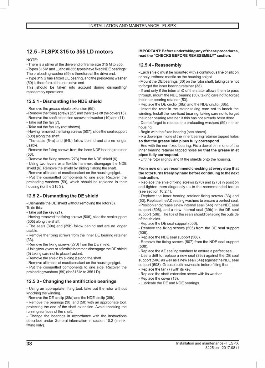
38
Installation and maintenance - FLSPX3225 en - 2017.08 / i
12.5 - FLSPX 315 to 355 LD motorsNOTE:- There is a stirrer at the drive end of frame size 315 M to 355. - Types 315 M and L, and all 355 types have fixed NDE bearings: The preloading washer (59) is therefore at the drive end.- Type 315 S has a fixed DE bearing, and the preloading washer (59) is therefore at the non drive end.This should be taken into account during dismantling/ reassembly operations.
12.5.1 - Dismantling the NDE shield- Remove the grease nipple extension (65).- Remove the fixing screws (27) and then take off the cover (13).- Remove the shaft extension screw and washer (10) and (11). - Take out the fan (7).- Take out the fan key (not shown).- Having removed the fixing screws (507), slide the seal support (508) along the shaft.- The seals (54a) and (54b) follow behind and are no longer usable.- Remove the fixing screws from the inner NDE bearing retainer (53).- Remove the fixing screws (273) from the NDE shield (6).- Using two levers or a flexible hammer, disengage the NDE shield (6). Remove the shield by sliding it along the shaft.- Remove all traces of mastic sealant on the housing spigot.- Put the dismantled components to one side. Recover the preloading washers (59), which should be replaced in their housing (for the 315 S).
12.5.2 - Dismantling the DE shield- Dismantle the DE shield without removing the rotor (3).To do this:- Take out the key (21).- Having removed the fixing screws (506), slide the seal support (505) along the shaft.- The seals (39a) and (39b) follow behind and are no longer usable.- Remove the fixing screws from the inner DE bearing retainer (33).- Remove the fixing screws (270) from the DE shield.- Using two levers or a flexible hammer, disengage the DE shield (5) taking care not to place it aslant.- Remove the shield by sliding it along the shaft.- Remove all traces of mastic sealant on the housing spigot.- Put the dismantled components to one side. Recover the preloading washers (59) (for 315 M to 355 LD).
12.5.3 - Changing the antifriction bearings- Using an appropriate lifting tool, take out the rotor without knocking the winding.- Remove the DE circlip (38a) and the NDE circlip (38b).- Remove the bearings (30) and (50) with an appropriate tool, protecting the end of the shaft extension. Avoid knocking the running surfaces of the shaft.- Change the bearings in accordance with the instructions described under General information in section 10.2 (shrink-fitting only).
IMPORTANT: Before undertaking any of these procedures, read the "CHECKS BEFORE REASSEMBLY" section.
12.5.4 - Reassembly- Each shield must be mounted with a continuous line of silicon or polyurethane mastic on the housing spigot.- Mount the DE bearings (30) on the rotor shaft, taking care not to forget the inner bearing retainer (33).- If and only if the internal Ø of the stator allows them to pass through, mount the NDE bearing (50), taking care not to forget the inner bearing retainer (53).- Replace the DE circlip (38a) and the NDE circlip (38b).- Insert the rotor in the stator taking care not to knock the winding. Install the non-fixed bearing, taking care not to forget the inner bearing retainer, if this has not already been done.- Do not forget to replace the preloading washers (59) in their housing.- Begin with the fixed bearing (see above).Fix a dowel pin in one of the inner bearing retainer tapped holes so that the grease inlet pipes fully correspond.- End with the non-fixed bearing. Fix a dowel pin in one of the inner bearing retainer tapped holes so that the grease inlet pipes fully correspond.- Lift the rotor slightly and fit the shields onto the housing.
From now on, we recommend checking at every step that the rotor turns freely by hand before continuing to the next instruction.- Replace the shield fixing screws (270) and (273) in position and tighten them diagonally up to the recommended torque (see section 10.2.4).- Replace the inner bearing retainer fixing screws (33) and (53). Replace the AZ sealing washers to ensure a perfect seal.- Position and grease a new internal seal (54b) in the NDE seal support (508), and a new internal seal (39b) in the DE seal support (506). The lips of the seals should be facing the outside of the shields.- Replace the DE seal support (506).- Remove the fixing screws (505) from the DE seal support (506).- Replace the NDE seal support (508).- Remove the fixing screws (507) from the NDE seal support (508).- Replace the AZ sealing washers to ensure a perfect seal.- Use a drift to replace a new seal (39a) against the DE seal support (506) as well as a new seal (54a) against the NDE seal support (508). Grease both new seals before fitting them.- Replace the fan (7) with its key.- Replace the shaft extension screw with its washer.- Replace the cover (13).- Lubricate the DE and NDE bearings.
INSTALLATION AND MAINTENANCE - FLSPX
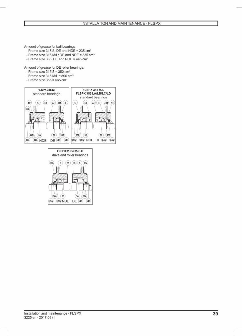
39
Installation and maintenance - FLSPX3225 en - 2017.08 / i
Amount of grease for ball bearings: - Frame size 315 S: DE and NDE = 235 cm3
- Frame size 315 M/L: DE and NDE = 335 cm3
- Frame size 355: DE and NDE = 445 cm3
Amount of grease for DE roller bearings: - Frame size 315 S = 350 cm3
- Frame size 315 M/L = 500 cm3
- Frame size 355 = 665 cm3
59
38b
6 53
38b 6 53
33 38a 5
50
39b
30508
50
39b
508
506
6 53 33 5 38a 44
33 5 38a
30508 506
54a54b 39b39a 54a54b
30 506
54a54b
50
39a
39a
FLSPX 315 STstandard bearings
FLSPX 315 to 355 LDdrive end roller bearings
NDE DE
NDE DE
FLSPX 315 M/LFLSPX 355 LA/LB/LC/LD
standard bearings
NDE DE
INSTALLATION AND MAINTENANCE - FLSPX

40
Installation and maintenance - FLSPX3225 en - 2017.08 / i
FLSPX 315 to 355 LD
727
10
11
6456
273508 507
12
13
59
7074
8953
50
64
181
2
3
5
4230
435
270 505 50640
271
21
406
33
65
270
122
26
54a
54b
39a
39b
FLSPX 315 to 355 LDRef. Description Ref. Description Ref. Description
1 Wound stator 35 Moving part of DE grease valve 74 Stator terminal box lid
2 Housing 39a DE external seal 81 Cable gland support plate
3 Rotor 39b DE internal seal 89 Connection - Terminal box
5 DE shield 40 Cover fixing screw 122 Stirrer (only from 315 M to 355 LD)
6 NDE shield 42 DE grease nipple 270 DE shield fixing screw
7 Fan 43 Extension for DE grease nipple 271 DE shield fixing nut
10 Turbine or fan screw 50 Non drive end bearing 273 NDE shield fixing screw
11 Lock washer (not shown) 53 Inner NDE bearing retainer 406 DE grease valve cover plate - (plug)
12 Lock washer 54a NDE external seal 456 NDE grease valve cover plate - (plug)
13 Fan cover 54b NDE internal seal 505 Fixing screw for DE seal support
21 Shaft extension key 56 Moving part of NDE grease valve 506 DE seal support
26 Nameplate 59 NDE preloading (wavy) washer 507 Fixing screw for NDE seal support
27 Fan cover screw 64 NDE grease nipple 508 DE seal support
30 DE washer 65 Extension for NDE grease nipple
33 Inner DE bearing retainer 70 Stator terminal box
INSTALLATION AND MAINTENANCE - FLSPX

41
Installation and maintenance - FLSPX3225 en - 2017.08 / i
13 - LS AND FLS MOTORS - ZONE 22
Refer to the general manual for LS and FLS series motors, ref. 3770.
INSTALLATION AND MAINTENANCE - FLSPX

42
Installation and maintenance - LSPX-FLSPX ZONE 21 – LS-FLS ZONE 223225 en - 2017.08 / i
NOTES

43
Installation and maintenance - LSPX-FLSPX ZONE 21 – LS-FLS ZONE 223225 en - 2017.08 / i
NOTES

Moteurs Leroy-SomerHeadquarter: Boulevard Marcellin Leroy - CS 10015
16915 ANGOULÊME Cedex 9
Limited company with capital of 65,800,512 €RCS Angoulême 338 567 258
www.leroy-somer.com