Embed Size (px)
DESCRIPTION
Manual
Citation preview

Thank you for purchasing a JL Audio amplifier for
your automotive sound system.
Your amplifier has been designed and manufactured to exacting
standards in order to ensure years of musical enjoyment in your
vehicle. For maximum performance and extended warranty
coverage, we highly recommend that you have your new amplifier
installed by an authorized JL Audio dealer. Your authorized
dealer has the training, expertise and installation equipment to
ensure optimum performance from this product. Should you
decide to install the amplifier yourself, please take the time
to read this manual thoroughly so as to familiarize yourself
with its installation requirements and setup procedures.
If you have any questions regarding the instructions in this
manual or any aspect of your amplifier’s operation, please contact
your authorized JL Audio dealer for assistance. If you need further
assistance, please call the JL Audio Technical Support Department at
(954) 443-1100 during business hours (Eastern Time Zone).
JL AUDIO 300/4 four-channel full-range amplifier
o w n e r ’ s m a n u a l
Downloaded from www.Manualslib.com manuals search engine

PLANNING YOUR INSTALLATIONIt is important that you take the time to read
this manual and that you plan out your installationcarefully.The following are some considerations that you must take into account when planning your installation.
Cooling Efficiency Considerations:Your JL Audio amplifier employs an advanced
type of heat management, called RealSink™.Thisfeature takes advantage of convection and radiationeffects to remove heat from the amplifier circuitry.For optimum cooling performance, the vertical heatsinks located at the back of the amplifier should beexposed to as large a volume of air as possible.Enclosing the amplifier in a small, poorly ventilatedchamber can lead to excessive heat build-up anddegraded performance. If an installation calls for anenclosure around the amplifier, we recommend thatthis enclosure be ventilated with the aid of a fan. Innormal applications, fan-cooling is not necessary, butyou still need to follow some basic guidelines:
• Amplifier mounted vertically with heat sink finspointing up: Optimum
• Amplifier mounted horizontally,right side up: Good
• Amplifier mounted horizontally, but upside down:Fair (not recommended if there is less than 1 inch(2.5 cm) clearance above the amplifier heat sinks)
• Amplifier mounted vertically with heat sink finspointing laterally: Fair
• Amplifier mounted vertically with heat sink finspointing down: Poor (not recommended)
If mounting the amplifier under a seat, make surethere is at least 1 inch (2.5 cm) of space above theamplifier heat sink fins to permit proper cooling.
Safety Considerations:Your amplifier needs to be installed in a dry,
well-ventilated environment and in a manner which does not interfere with your vehicle’s safetyequipment (air bags, seat belt systems,ABS brakesystems, etc.).You should also take the time tosecurely mount the amplifier using the suppliedscrews so that it does not come loose in the eventof a collision or a sudden jolt to the vehicle (15 lbs.of aluminum traveling at 60 MPH will hurt you).
Stupid Mistakes to Avoid:• Check before drilling any holes in your vehicle to
make sure that you will not be drilling through agas tank, brake line, wiring harness or other vitalvehicle system.
• Do not run system wiring outside or underneaththe vehicle.This is an extremely dangerouspractice which can result in severe damage toyour vehicle and person.
• Protect all system wires from sharp metal edges and wear by carefully routing them,tying them down and using grommets and loom where appropriate.
• Do not mount the amplifier in the enginecompartment, under the vehicle, on the roof or in any other area that will expose the amplifiercircuitry to the elements.
JL AUDIO 300/4 3
Front ChannelInput Voltage
Range Selector(pg. 6)
Front ChannelFilter Slope Selection
(pg. 7)Front ChannelFilter Frequency Range Selector
(pg. 8)
Front ChannelInput Sensitivity
Control(pg. 6)
Front ChannelLeft and Right
Input Jacks(pg. 6)
Front ChannelInput Mode
Selector(pg. 6)
Front ChannelSpeaker Outputs
(pg. 8)
Rear ChannelSpeaker Outputs
(pg. 8)
Front ChannelFilter Cutoff
Frequency Selector(pg. 8)
Front ChannelFilter Mode
Selector(pg. 7)
Rear ChannelLeft and Right
Input Jacks(pg. 6)
Remote Turn-On Connector
(pg. 6)
Chassis Ground Connector
(pg. 5)
+12 V Power Connector
(pg. 5)
Rear ChannelInput Voltage
Range Selector(pg. 6)
Rear ChannelFilter Slope Selection
(pg. 7)Rear ChannelFilter Frequency Range Selector
(pg. 8)
Rear ChannelInput Sensitivity
Control(pg. 6)
Rear ChannelFilter Mode
Selector(pg. 7)
Rear ChannelFilter Cutoff
Frequency Selector(pg. 8)
PROTECT YOUR HEARING! We value you as a long-term customer. For that
reason, we urge you to practice restraint in theoperation of this product so as not to damage yourhearing and that of others in your vehicle. Studieshave shown that continuous exposure to highsound pressure levels can lead to permanent(irreparable) hearing loss.This and all other high-power amplifiers are capable of producing such highsound pressure levels when connected to a speakersystem. Please limit your continuous exposure tohigh volume levels.
While driving, operate your audio system in amanner that still allows you to hear necessary noisesto operate your vehicle safely (horns, sirens, etc.).
SERIAL NUMBER In the event that your amplifier requires service
or is ever stolen, you will need to have a record ofthe product’s serial number. Please take the time toenter that number in the space provided below.The serial number can be found on the bottompanel of the amplifier and on the amplifier packaging.
Serial Number:
_______________________________
INSTALLATION APPLICATIONSThis amplifier is designed for operation in vehicles
with 12V, negative-ground electrical systems. Use ofthis product in vehicles with positive ground and/orvoltages other than 12V may result in damage to theproduct and will void the warranty.
This product is not certified or approved foruse in aircraft.
Do not attempt to “bridge” the outputs of thisamplifier with the outputs of a second amplifier,including an identical one.
2 JL AUDIO 300/4
Downloaded from www.Manualslib.com manuals search engine
11) Connect the speaker wires to the amplifier.12) Carefully review the amplifier’s control
settings to make sure that they are set according tothe needs of the system.
13) Install power wire fuse (40A for a single 300/4) and reconnect the negative battery post terminal.
14) Turn on the source unit at a low level to double-check that the amplifier is configuredcorrectly. Resist the temptation to crank it up untilyou have verified the control settings.
15) Make necessary adjustments to the inputsensitivity controls of the front and rear channelsections to obtain the right overall output and thedesired balance between their outputs. SeeAppendix B (page 14) for the recommended inputsensitivity setting method.
16) Enjoy the fruits of your labor with yourfavorite music.
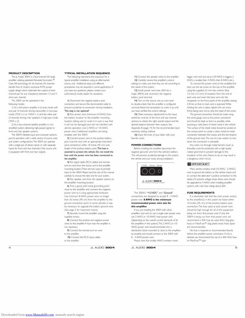
POWER CONNECTIONSBefore installing the amplifier, disconnect the
negative (ground) wire from the vehicle's battery.This will prevent accidental damage to the system,the vehicle and your body during installation.
The 300/4's “+12 VDC” and “Ground”connections are designed to accept 8 - 4 AWGpower wire. 8 AWG is the minimumrecommended power wire size for this amplifier.
If you are installing the 300/4 with otheramplifiers and wish to use a single main power wire,use 2 AWG or 1/0 AWG main power wire(depending on the overall current demands of allthe amplifiers in the system).This 2 AWG or 1/0AWG power wire should terminate into adistribution block mounted as close to the amplifiersas possible and should connect to the 300/4 with 8 - 4 AWG power wire.
Please note that smaller AWG numbers mean
bigger wire and vice-versa (1/0 AWG is biggest, 2AWG is smaller, then 4 AWG, then 8 AWG, etc.).
To connect the power wires to the amplifier, firstback out the set screw on the top of the amplifier,using the supplied 2.5 mm hex wrench. Strip 1/2 inch (12 mm) of insulation from the end ofeach wire and insert the bare wire into thereceptacle on the front panel of the amplifier, seatingit firmly so that no bare wire is exposed.Whileholding the wire in place, tighten the set screwfirmly, taking care not to strip the head of the screw.
The ground connection should be made usingthe same gauge wire as the power connection and should be kept as short as possible, whileaccessing a solid piece of sheet metal in the vehicle.The surface of the sheet metal should be sanded atthe contact point to create a clean, metal-to-metalconnection between the chassis and the terminationof the ground wire.The use of a star washer to lockdown the connection is advisable.
Any wires run through metal barriers (such asfirewalls), must be protected with a high qualityrubber grommet to prevent damage to theinsulation of the wire. Failure to do so may result ina dangerous short circuit.
Many vehicles employ small (10 AWG - 6 AWG)wire to ground the battery to the vehicle chassis andto connect the alternator's positive connection to thebattery.To prevent voltage drops, these wires shouldbe upgraded to 4 AWG when installing amplifiersystems with main fuse ratings above 60A.
FUSE REQUIREMENTSIt is absolutely vital that the main power wire(s)
to the amplifier(s) in the system be fused within18 inches (45 cm) of the positive battery postconnection.The fuse value at each power wireshould be high enough for all of the equipmentbeing run from that power wire. If only the 300/4 is being run from that power wire, werecommend a 40A fuse be used. AGU (big glassfuse) or MaxiFuse™ (big plastic-body fuse) typesare recommended.
No fuse is required or recommended directlybefore the amplifier power connection. If one isdesired, we recommend the use of a 40A AGU fuseor MaxiFuse™ type.
IMPORTANT!
JL AUDIO 300/4 5
PRODUCT DESCRIPTIONThe JL Audio 300/4 is a four-channel full-range
amplifier utilizing patented Absolute Symmetry™Class AB technology for all channels.All channelsbenefit from JL Audio's exclusive R.I.P.S. powersupply design which optimizes the output of eachchannel pair for any impedance between 1.5 and 4ohms per channel.
The 300/4 can be operated in the following modes:
1) As a full-system amplifier in bi-amp mode withone pair of channels driving subwoofers in low-passmode (75W x 2 or 150W x 1) and the other pairof channels driving main speakers in high-pass mode(75W x 2).
2) As a four-channel satellite amplifier in a bi-amplified system, delivering high-passed signals tofront and rear speaker systems.
The 300/4's flexible input and crossover sectionspermit operation with a wide variety of source unitsand system configurations.The 300/4 can operatewith a single pair of stereo inputs or with separateinputs for front and rear channels, if the source unitis equipped with front and rear outputs.
TYPICAL INSTALLATION SEQUENCEThe following represents the sequence for a
typical amplifier installation, using an aftermarketsource unit. Additional steps and differentprocedures may be required in some applications. Ifyou have any questions, please contact yourauthorized JL Audio dealer for assistance.
1) Disconnect the negative battery postconnection and secure the disconnected cable toprevent accidental re-connection during installation.This step is not optional!
2) Run power wire (minimum 8 AWG) fromthe battery location to the amplifier mountinglocation, taking care to route it in such a way thatit will not be damaged and will not interfere withvehicle operation. Use 2 AWG or 1/0 AWGpower wire if additional amplifiers are beinginstalled with the 300/4.
3) Connect power wire to the positive batterypost. Fuse the wire with an appropriate fuse block(and connectors) within 18 inches (45 cm) wirelength of the positive battery post. This fuse isessential to protect the vehicle. Do not install thefuse until the power wire has been connected tothe amplifier.
4) Run signal cables (RCA cables) and remoteturn-on wire from the source unit to the amplifiermounting location.There are two ways to provideinput to the 300/4. Please read the rest of this manualcarefully to choose the best one for your system.
5) Run speaker wire from the speaker systems tothe amplifier mounting location.
6) Find a good, solid metal grounding pointclose to the amplifier and connect the negativepower wire to it using appropriate hardware.Use minimum 8 AWG power wire, no longerthan 36 inches (90 cm) from the amplifier to theground connection point. In some vehicles, it maybe necessary to upgrade the battery ground wire.(See page 5 for important notice).
7) Securely mount the amplifier using thesupplied screws.
8) Connect the positive and negative power wires to the amplifier.A fuse near the amplifier isnot necessary.
9) Connect the remote turn-on wire to the amplifier.
10) Connect the RCA input cables to the amplifier.
4 JL AUDIO 300/4
Downloaded from www.Manualslib.com manuals search engine

each pair of amplifier channels for maximum cleanoutput. Rotating the control clockwise will result inhigher sensitivity (louder for a given input voltage).Rotating the control counter-clockwise will result inlower sensitivity (quieter for a given input voltage.)
To properly set each pair of amplifier channelsfor maximum clean output, please refer toAppendix B (page 14) in this manual. After usingthis procedure, you can then adjust the relativelevel of each channel pair by adjusting the inputsensitivity downward on either or both channelpairs, if they require attenuation to achieve thedesired system balance.
Do not increase the “Input Sens.” setting forany amplifier in the system beyond the maximumlevel established during the procedure outlined inAppendix B (page 14). Doing so will result inaudible distortion and possible speaker damage.
Be aware that both “Input Sens.” adjustmentswill have to be made, regardless of how many inputcables are feeding the amplifier.These controls willallow you to set the appropriate relative levels forfront and rear channels and any other amplifierchannels in the system.
CROSSOVER CONTROLSCrossovers are groups of individual electronic filterswhich allow only certain frequency ranges to passthrough them by attenuating frequencies outsidethe selected range.These filters allow the user tospecify what frequency range will be sent out ofeach channel section of the amplifier.This, in turn,allows each speaker system to only reproduce arange of frequencies it is well-suited for, resulting inreduced distortion and improved fidelity.
Front and Rear Filter Section:
The 300/4 employs two separate, but identical filtersections for its front and rear channel pairs.Thesesections consist of the following controls1) “Filter Mode” Control:This switch allows you toconfigure the filter into one of two filter types ordefeat it completely:“Off”: Defeats the filter for that channel sectioncompletely, allowing the full range of frequenciespresent at the inputs to feed that pair of channels.This is useful for systems utilizing outboardcrossovers or requiring full-range reproduction fromthat pair of channels.“LP” (Low-Pass): Configures the filter to attenuatefrequencies above the selected filter frequency.Useful for connection of subwoofer(s) to thatchannel section.“HP” (High-Pass): Configures the filter to attenuatefrequencies below the selected filter frequency.Useful for connection of component speakers tothat channel section in a bi-amplified system.
2) “Filter Slope” Control: This switch allowsyou to select from two filter slopes for thatchannel section.“12dB”: Configures the filter to attenuatefrequencies above or below the selected filterfrequency at a rate of 12 dB per octave(Butterworth alignment).“24dB”: Configures the filter to attenuatefrequencies above or below the selected filter
JL AUDIO 300/4 7
TURN-ON LEADThe 300/4 uses a conventional +12V remote
turn-on lead, typically controlled by the source unit'sremote turn-on output.The amplifier will turn onwhen +12V is present at its “Remote” input andturn off when +12V is switched off. If a source unitdoes not have a dedicated remote turn-on output,the amplifier’s turn-on lead can be connected to+12V via a switch that derives power from anignition-switched circuit.
The 300/4's “Remote” turn-on connector isdesigned to accept 18 AWG – 8 AWG wire.12 AWG is more than adequate for this purpose.To connect the remote turn-on wire to theamplifier, first back out the set screw on the top ofthe amplifier, using the supplied hex wrench. Strip1/2 inch (12mm) of wire and insert the bare wireinto the receptacle on the front panel of theamplifier, seating it firmly so that no bare wire isexposed.When using smaller wire, it may benecessary to strip 1 inch of insulation from the wireand fold the bare wire in half prior to insertion.While holding the wire in the terminal, tighten theset screw firmly, taking care not to strip the head ofthe screw and making sure that the wire is firmlygripped by the set screw.
FRONT AND REAR INPUT SECTIONSThe 300/4 has two separate input sections, one
for its front channels and another for its rearchannels. Each section contains a pair of RCA-typeinput jacks, an “Input Voltage” switch and an “InputSens.” rotary control.
The “Front Input Section” also contains an “InputMode” switch to allow operation of all four amplifierchannels with one or two pairs of input signals.
1) Input Mode Switch: If you wish to operate allfour channels of the 300/4 with a single pair ofstereo inputs, select the “2ch” position on the“Input Mode” switch and connect a single pair ofinput cables to the input jacks in the “Front Input
Section”. In this mode, the amplifier will route thesignals connected to the front inputs to the rearinputs as well.
If you wish to use separate inputs for the frontand rear channel cections (to allow front-to-rearfading, for example) and the source unit isequipped with front and rear outputs, select“4ch” on the “Input Mode” switch. In this mode,you must connect separate pairs of input cablesto each input section.
2) Input Voltage Range: A wide range of signalinput voltages can be accommodated by each ofthe 300/4's input sections (200mV – 8V).This widerange is split up into two sub-ranges, accessible viaswitches located in each input section of theamplifier. Be aware that each input section's “InputVoltage” switch will have to be configured,regardless of how many input cables are actuallyfeeding the amplifier.
The “Low” position on each “Input Voltage”switch selects an input sensitivity range between200mV and 2V.This means that the “Input Sens.”rotary control will operate within that voltagewindow. If you are using an aftermarket source unit,with conventional preamp-level outputs, this is mostlikely the position that you will use.
The “High” position on each “Input Voltage”switch selects an input sensitivity range between800mV and 8V.This is useful for certain high-outputpreamp level signals as well as speaker-level outputfrom source units and small amplifiers.To usespeaker-level sources, splice the speaker outputwires of the source unit or small amplifier onto apair of RCA plugs for each input pair.
The output of the amplifier will decrease for agiven input voltage when the “Input Range” switchis placed in the “High” position. Conversely, theoutput will be higher with the switch in the “Low”position.While this may sound counter-intuitive, it isconsistent with the descriptions above.
3) Input Sensitivity Adjustment: Located next tothe “Input Voltage” switch in each input section is arotary control labeled “Input Sens.”. Once theappropriate “Input Voltage” range has beenselected, this control can be used to match thesource unit's output voltage to the input stage of
IMPORTANT!
6 JL AUDIO 300/4
Downloaded from www.Manualslib.com manuals search engine
For optimum power output at all four channels,connect the same impedance (between 1.5-4Ω) onall four channels. On pages 16 and 17 are chartsshowing the continuous (RMS) power outputcapability of the 300/4 into various combinations offront and rear impedances (optimum output isshown in bold type). Please refer to these charts soyou know what to expect in terms of poweroutput.
If you connect a load higher than 4Ω nominalper channel in stereo mode (or 8Ω in bridgedmode), power will drop by half with everydoubling of impedance above 4Ω stereo / 8Ωmono. If you connect a load lower than 1.5Ωnominal per channel in stereo mode (or 3Ω inbridged mode, the amplifier protection circuitryactivates a “safe” mode which reduces amplifierpower to protect the circuitry from failure (theyellow “Low Ω” LED lights to indicate that thishas happened). See page 10 for details.
Speaker loads below 1.5Ω nominal per channelin stereo or 3Ω nominal in bridged mode are notrecommended and may cause the amplifier outputto distort excessively.
IMPORTANT!
IMPORTANT!
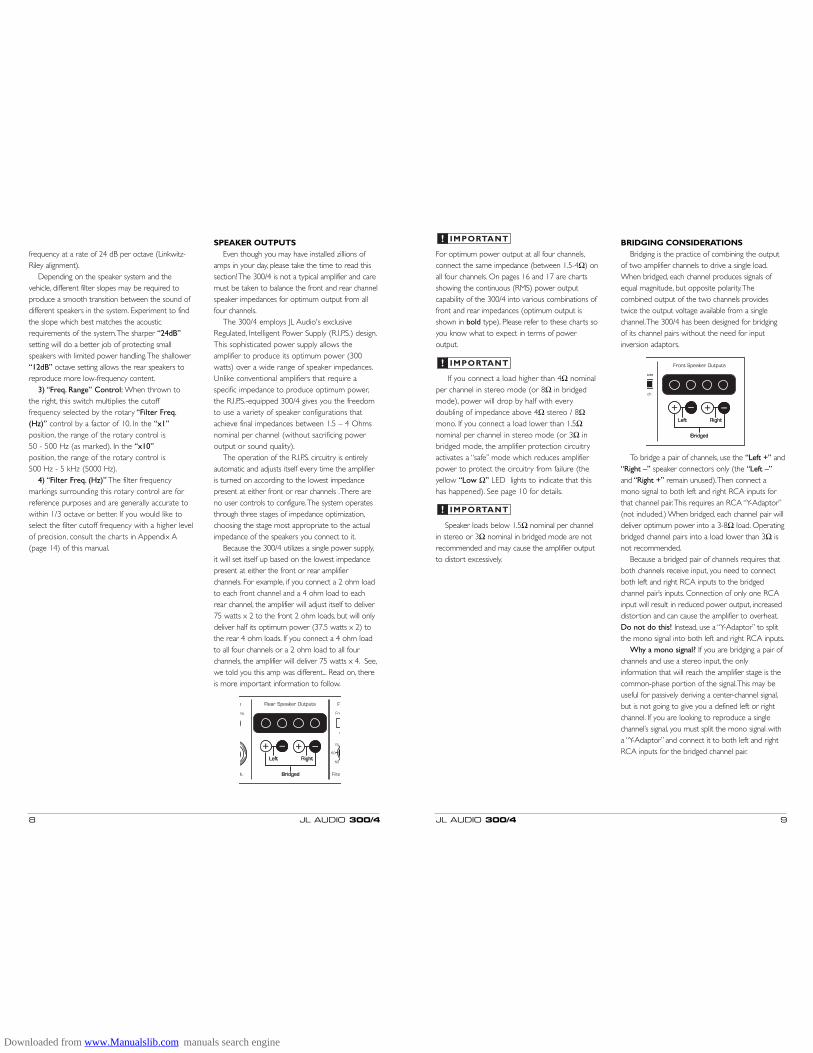
IMPORTANT! BRIDGING CONSIDERATIONSBridging is the practice of combining the output
of two amplifier channels to drive a single load.When bridged, each channel produces signals ofequal magnitude, but opposite polarity.Thecombined output of the two channels providestwice the output voltage available from a singlechannel.The 300/4 has been designed for bridgingof its channel pairs without the need for inputinversion adaptors.
To bridge a pair of channels, use the “Left +” and“Right –” speaker connectors only (the “Left –”and “Right +” remain unused).Then connect amono signal to both left and right RCA inputs forthat channel pair.This requires an RCA “Y-Adaptor”(not included.) When bridged, each channel pair willdeliver optimum power into a 3-8Ω load. Operatingbridged channel pairs into a load lower than 3Ω isnot recommended.
Because a bridged pair of channels requires thatboth channels receive input, you need to connectboth left and right RCA inputs to the bridgedchannel pair’s inputs. Connection of only one RCAinput will result in reduced power output, increaseddistortion and can cause the amplifier to overheat.Do not do this! Instead, use a “Y-Adaptor” to splitthe mono signal into both left and right RCA inputs.
Why a mono signal? If you are bridging a pair ofchannels and use a stereo input, the onlyinformation that will reach the amplifier stage is thecommon-phase portion of the signal.This may beuseful for passively deriving a center-channel signal,but is not going to give you a defined left or rightchannel. If you are looking to reproduce a singlechannel’s signal, you must split the mono signal witha “Y-Adaptor” and connect it to both left and rightRCA inputs for the bridged channel pair.
JL AUDIO 300/4 9
frequency at a rate of 24 dB per octave (Linkwitz-Riley alignment).
Depending on the speaker system and thevehicle, different filter slopes may be required toproduce a smooth transition between the sound ofdifferent speakers in the system. Experiment to findthe slope which best matches the acousticrequirements of the system.The sharper “24dB”setting will do a better job of protecting smallspeakers with limited power handling.The shallower“12dB” octave setting allows the rear speakers toreproduce more low-frequency content.
3) “Freq. Range” Control: When thrown tothe right, this switch multiplies the cutofffrequency selected by the rotary “Filter Freq.(Hz)” control by a factor of 10. In the “x1”position, the range of the rotary control is 50 - 500 Hz (as marked). In the “x10”position, the range of the rotary control is 500 Hz - 5 kHz (5000 Hz).
4) “Filter Freq. (Hz)” The filter frequencymarkings surrounding this rotary control are forreference purposes and are generally accurate towithin 1/3 octave or better. If you would like toselect the filter cutoff frequency with a higher levelof precision, consult the charts in Appendix A(page 14) of this manual.
SPEAKER OUTPUTSEven though you may have installed zillions of
amps in your day, please take the time to read thissection! The 300/4 is not a typical amplifier and caremust be taken to balance the front and rear channelspeaker impedances for optimum output from allfour channels.
The 300/4 employs JL Audio's exclusiveRegulated, Intelligent Power Supply (R.I.P.S.) design.This sophisticated power supply allows theamplifier to produce its optimum power (300watts) over a wide range of speaker impedances.Unlike conventional amplifiers that require aspecific impedance to produce optimum power,the R.I.P.S.-equipped 300/4 gives you the freedomto use a variety of speaker configurations thatachieve final impedances between 1.5 – 4 Ohmsnominal per channel (without sacrificing poweroutput or sound quality).
The operation of the R.I.P.S. circuitry is entirelyautomatic and adjusts itself every time the amplifieris turned on according to the lowest impedancepresent at either front or rear channels .There areno user controls to configure.The system operatesthrough three stages of impedance optimization,choosing the stage most appropriate to the actualimpedance of the speakers you connect to it.
Because the 300/4 utilizes a single power supply,it will set itself up based on the lowest impedancepresent at either the front or rear amplifierchannels. For example, if you connect a 2 ohm loadto each front channel and a 4 ohm load to eachrear channel, the amplifier will adjust itself to deliver75 watts x 2 to the front 2 ohm loads, but will onlydeliver half its optimum power (37.5 watts x 2) tothe rear 4 ohm loads. If you connect a 4 ohm loadto all four channels or a 2 ohm load to all fourchannels, the amplifier will deliver 75 watts x 4. See,we told you this amp was different... Read on, thereis more important information to follow.
8 JL AUDIO 300/4
Downloaded from www.Manualslib.com manuals search engine
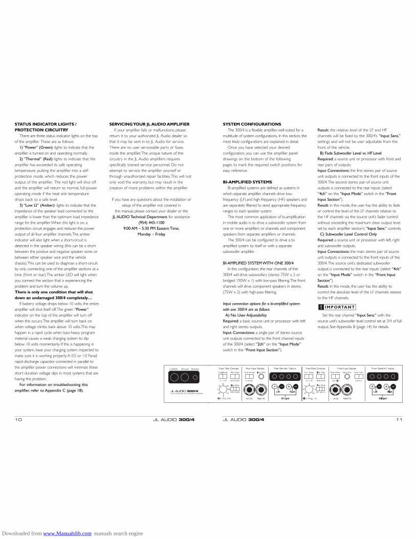
SYSTEM CONFIGURATIONSThe 300/4 is a flexible amplifier, well-suited for a
multitude of system configurations. In this section, themost likely configurations are explained in detail.
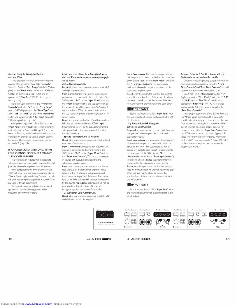
Once you have selected your desiredconfiguration, you can use the amplifier paneldrawings on the bottom of the following pages to mark the required switch positions foreasy reference.
BI-AMPLIFIED SYSTEMSBi-amplified systems are defined as systems in
which separate amplifier channels drive low-frequency (LF) and high-frequency (HF) speakers andare separately filtered to send appropriate frequencyranges to each speaker system.
The most common application of bi-amplificationin mobile audio is to drive a subwoofer system fromone or more amplifiers or channels and componentspeakers from separate amplifiers or channels.
The 300/4 can be configured to drive a bi-amplified system by itself or with a separatesubwoofer amplifier.
BI-AMPLIFIED SYSTEM WITH ONE 300/4In this configuration, the rear channels of the
300/4 will drive subwoofers (stereo 75W x 2 orbridged 150W x 1) with low-pass filtering.The frontchannels will drive component speakers in stereo(75W x 2) with high-pass filtering.
Input connection options for a bi-amplified systemwith one 300/4 are as follows:
A) No User AdjustabilityRequired: a basic source unit or processor with leftand right stereo outputs.Input Connections: a single pair of stereo sourceunit outputs connected to the front channel inputsof the 300/4 (select “2ch” on the “Input Mode”switch in the “Front Input Section”).
Result: the relative level of the LF and HFchannels will be fixed by the 300/4’s “Input Sens.”settings and will not be user adjustable from thefront of the vehicle.
B) Fade Subwoofer Level vs. HF LevelRequired: a source unit or processor with front andrear pairs of outputs.Input Connections: the first stereo pair of sourceunit outputs is connected to the front inputs of the300/4.The second stereo pair of source unitoutputs is connected to the rear inputs (select“4ch” on the “Input Mode” switch in the “FrontInput Section”).Result: in this mode, the user has the ability to fadeor control the level of the LF channels relative tothe HF channels via the source unit’s fader controlwithout exceeding the maximum clean output levelset by each amplifier section’s “Input Sens.” controls.
C) Subwoofer Level Control OnlyRequired: a source unit or processor with left, rightand subwoofer outputs.Input Connections: the main stereo pair of sourceunit outputs is connected to the front inputs of the300/4.The source unit’s dedicated subwooferoutput is connected to the rear inputs (select “4ch”on the “Input Mode” switch in the “Front InputSection”).Result: in this mode, the user has the ability tocontrol the absolute level of the LF channels relativeto the HF channels.
Set the rear channel “Input Sens.” with thesource unit’s subwoofer level control set at 3/4 of fulloutput. See Appendix B (page 14) for details.
IMPORTANT!
JL AUDIO 300/4 11
STATUS INDICATOR LIGHTS / PROTECTION CIRCUITRY
There are three status indicator lights on the topof the amplifier. These are as follows:
1) “Power” (Green): lights to indicate that theamplifier is turned on and operating normally.
2) “Thermal” (Red): lights to indicate that theamplifier has exceeded its safe operatingtemperature, putting the amplifier into a self-protection mode, which reduces the poweroutput of the amplifier. The red light will shut offand the amplifier will return to normal, full-poweroperating mode if the heat sink temperaturedrops back to a safe level.
3) “Low Ω” (Amber): lights to indicate that theimpedance of the speaker load connected to theamplifier is lower than the optimum load impedancerange for the amplifier.When this light is on, aprotection circuit engages and reduces the poweroutput of all four amplifier channels.The amberindicator will also light when a short-circuit isdetected in the speaker wiring (this can be a shortbetween the positive and negative speaker wires orbetween either speaker wire and the vehiclechassis).This can be used to diagnose a short-circuitby only connecting one of the amplifier sections at atime (front or rear).The amber LED will light whenyou connect the section that is experiencing theproblem and turn the volume up.There is only one condition that will shutdown an undamaged 300/4 completely…
If battery voltage drops below 10 volts, the entireamplifier will shut itself off.The green “Power”indicator on the top of the amplifier will turn offwhen this occurs.The amplifier will turn back onwhen voltage climbs back above 10 volts.This mayhappen in a rapid cycle when bass-heavy programmaterial causes a weak charging system to dipbelow 10 volts momentarily. If this is happening inyour system, have your charging system inspected tomake sure it is working properly.A 0.5 or 1.0 Faradrapid-discharge capacitor connected in parallel tothe amplifier power connections will minimize theseshort duration voltage dips in most systems that arehaving this problem.
For information on troubleshooting thisamplifier, refer to Appendix C (page 18).
SERVICING YOUR JL AUDIO AMPLIFIERIf your amplifier fails or malfunctions, please
return it to your authorized JL Audio dealer sothat it may be sent in to JL Audio for service.There are no user serviceable parts or fusesinside the amplifier.The unique nature of thecircuitry in the JL Audio amplifiers requiresspecifically trained service personnel. Do notattempt to service the amplifier yourself orthrough unauthorized repair facilities.This will notonly void the warranty, but may result in thecreation of more problems within the amplifier.
If you have any questions about the installation orsetup of the amplifier not covered in
this manual, please contact your dealer or the JL AUDIO Technical Department for assistance:
(954) 443-11009:00 AM – 5:30 PM Eastern Time,
Monday – Friday
10 JL AUDIO 300/4
Downloaded from www.Manualslib.com manuals search engine
Input Connections: The main stereo pair of sourceunit outputs is connected to the front inputs of the300/4 (select “2ch” on the “Input Mode” switch inthe “Front Input Section”).The source unit’sdedicated subwoofer output is connected to thesubwoofer amplifier inputs.Result: with this option, the user has the ability tocontrol the absolute level of the subwoofer channelrelative to the HF channels, but cannot fade thefront and rear HF channels relative to each other.
Set the subwoofer amplifier’s “Input Sens.” withthe source unit’s subwoofer level control set at 3/4of full output.
D) Front to Rear HF Fading and Subwoofer Level ControlRequired: a source unit or processor with front andrear pairs of stereo outputs plus a dedicatedsubwoofer output.Input Connections: one stereo pair (front, typically)of source unit outputs is connected to the frontinputs of the 300/4. The second stereo pair ofsource unit outputs (rear, typically) is connected tothe rear inputs of the 300/4 (select “4ch” on the“Input Mode” switch in the “Front Input Section”).The source unit’s dedicated subwoofer output isconnected to the subwoofer amplifier inputs.Result: with this option, the user has the ability tofade the front and rear HF channels relative to eachother and also has the ability to control theabsolute level of the subwoofer channel relative tothe HF channels.
Set the subwoofer amplifier’s “Input Sens.” withthe source unit’s subwoofer level control set at 3/4of full output.
IMPORTANT!
IMPORTANT!
Crossover Setup for Bi-Amplified System with one300/4 and a separate subwoofer amplifier:
Once the input and preamp output sections havebeen configured appropriately, go to the “FrontFilter Controls” and “Rear Filter Controls” You willset both control sections identically to start:
Select “x1” on the “Freq. Range” switch, “HP”(high-pass) on the “Filter Mode” switch and “12dB”or “24dB” on the “Filter Slope” switch and anappropriate “Filter Freq.” (80 - 90 Hz is a goodstarting point). Select the same settings for the“Rear Filter Controls”.
After proper adjustment of the 300/4’s front andrear “Input Sens.” controls, and the subwooferamplifier’s input sensitivity controls, you can fine tunefilter frequencies and slopes and attenuate eitherpair of channels to achieve proper balance. Forproper adjustment of the “Input Sens.” controls ofthe 300/4 use the method shown in Appendix B(page 14). For precise filter frequency informationfor the 300/4 refer to Appendix A (page 14). Referto the subwoofer amplifier owner’s manual forproper adjustments.
JL AUDIO 300/4 13
Crossover Setup for Bi-Amplified System with one 300/4:
Once the input sections have been configuredappropriately, go to the “Rear Filter Controls”.Select “x1” on the “Freq. Range” switch, “LP” (low-pass) on the “Filter Mode” switch and “12dB” or“24dB” on the “Filter Slope” switch and anappropriate “Filter Freq.” (80-90 Hz is a goodstarting point).
Next, turn your attention to the “Front FilterControls” and select “x1” on the “Freq. Range”switch, “HP” (high-pass) on the “Filter Type” switchand “12dB” or “24dB” on the “Filter Mode/Slope”switch and an appropriate “Filter Freq.” (again, 80-90 Hz is a good starting point).
After proper adjustment of the front and rear“Input Range” and “Input Sens.” controls using themethod shown in Appendix B (page 14), you canfine tune filter frequencies and slopes and attenuateeither pair of channels to achieve proper balance.For precise filter frequency information refer toAppendix A (page 14).
BI-AMPLIFIED SYSTEM WITH ONE 300/4 INFOUR-CHANNEL MODE AND A SEPARATESUBWOOFER AMPLIFIER
This configuration requires that the separatesubwoofer amplifier has a built-in low-pass filter. AllJLAudio subwoofer amplifiers have this feature.
In this configuration, the front channels of the300/4 will drive front component speakers (stereo75W x 2) with high-pass filtering.The rear channelswill drive rear component speakers in stereo (75Wx 2), also with high-pass filtering.
The separate amplifier will drive the subwoofersystem with low-pass filtering (select a filterfrequency of 80-90 Hz to start).
Input connection options for a bi-amplified systemwith one 300/4 and a separate subwoofer amplifierare as follows:A) No User AdjustabilityRequired: a basic source unit or processor with leftand right stereo outputs.Input Connections: a single pair of stereo sourceunit outputs is connected to the front inputs of the300/4 (select “2ch” on the “Input Mode” switch inthe “Front Input Section”) and also connected tothe subwoofer amplifier inputs (via a “Y-Adaptor”).Alternatively, the 300/4 can receive its input fromthe subwoofer amplifier’s preamp output set to “full-range” mode.Result: the relative level of the LF and front and rearHF channels will be fixed by the 300/4’s “InputSens.” settings (as well as the subwoofer amplifier’ssettings) and will not be user adjustable from thefront of the vehicle.
B) Fade Subwoofer Level vs. HF LevelRequired: a source unit or processor with front andrear pairs of stereo outputs.Input Connections: one stereo pair of source unitoutputs is connected to the front inputs of the300/4 (select “2ch” on the “Input Mode” switch inthe “Front Input Section”).The second stereo pairof source unit outputs is connected to thesubwoofer amplifier inputs.Result: with this option, the user has the ability tofade the level of the subwoofer amplifier’s inputrelative to the HF channels, but cannot controlfront-to-rear fading of the HF channels.The relativelevel of the front and rear HF channels will be fixedby the 300/4’s “Input Sens.” settings and will not beuser adjustable from the front of the vehicle.fading the signal to the subwoofer amplifier.
C) Subwoofer Level Control OnlyRequired: a source unit or processor with left, rightand dedicated subwoofer outputs.
12 JL AUDIO 300/4
Downloaded from www.Manualslib.com manuals search engine
JL AUDIO 300/4 15
The Nine-Step Procedure(follow this procedure for each pair of channels)
1) Disconnect the speaker(s) from the amplifier’s “Front Speaker Outputs” and“Rear Speaker Outputs”connectors.
2) Turn off all processing on the source unit(bass/treble, loudness, EQ, etc.). Set fader control tocenter position and subwoofer level control to 3/4of maximum (if used to drive the 300/4).
3) Switch the “Input Voltage” to “Low” andturn the “Input Sens.” control on both sets ofchannels all the way down.
4) Set the source unit volume to 3/4 of fullvolume. If either set of channels is being driven by asource unit’s dedicated subwoofer output, alsoadjust the source unit’s subwoofer level control to3/4 of maximum output.This will allow forreasonable gain overlap with moderate clipping atfull volume.
5) Using the listings on the following pages(pages 16 & 17), find the configuration thatmatches your specific speaker impedance asconnected to the 300/4. Make sure you notewhether your channels are in stereo or bridgedand use the appropriate listing section. Once youhave found your configuration, note the targetvoltage for input sensitivity adjustment for eachchannel section.This target voltage is listed inparentheses as “(set to “x” volts)”.
6) Verify that you have disconnected thespeakers before proceeding. Play a track with anappropriate sine wave (within the frequency rangeto be amplified by each set of channels) at 3/4source unit volume.
7) Connect the AC voltmeter to the “FrontSpeaker Outputs” or “Rear Speaker Outputs”connectors of the amplifier. If the channel pair isoperating in stereo, it is only necessary to measureone channel. If bridged, make sure you test thevoltage at the correct connectors (L+ and R–).
8) Increase the “Input Sens.” control until thetarget voltage is delivered for that set of channels.If excessive voltage is read on either set of channelswith the control at minimum (full counterclockwise),switch the appropriate “Input Voltage” switch to“High” and re-adjust.
9) Once you have adjusted each set ofchannels to its maximum low-distortion outputlevel, reconnect the speaker(s).The “Input Sens.”controls can now be adjusted downward if eitheror both sets of channels requires attenuation toachieve the desired system balance.
Do not increase any “Input Sens.” setting inthe system beyond the maximum level establishedduring this procedure. Doing so will result inaudible distortion and possible speaker damage.
It will be necessary to re-adjust the “InputSens.” for the affected channels if any equalizerboost is activated after setting the “Input Sens.”with this procedure.This applies to any EQ boostcircuit, including source unit tone controls or EQcircuits. EQ cuts will not require re-adjustment.
TARGET VOLTAGECHARTS ARE ON THE
NEXT TWO PAGES
IMPORTANT!
(continued on next page)
14 JL AUDIO 300/4
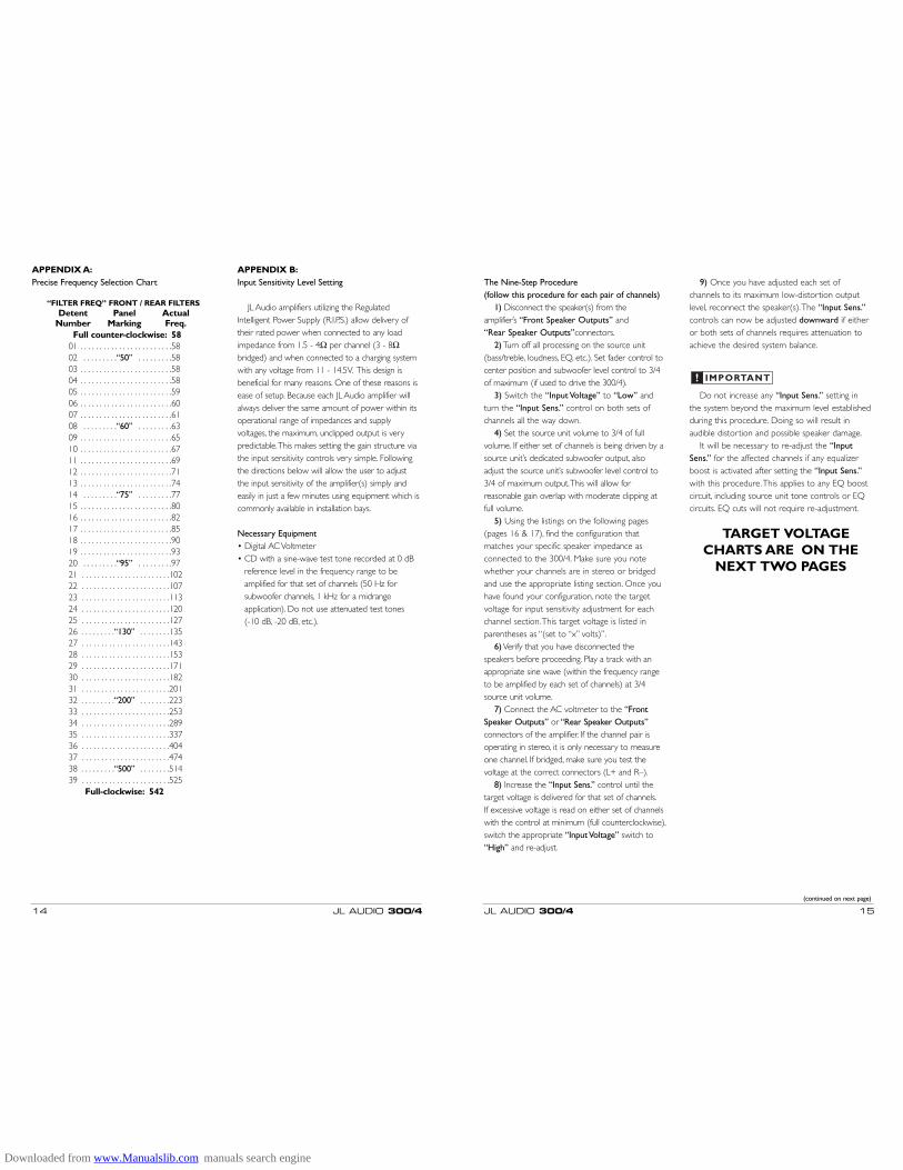
APPENDIX A:Precise Frequency Selection Chart
“FILTER FREQ” FRONT / REAR FILTERSDetent Panel Actual
Number Marking Freq.Full counter-clockwise: 58
01 . . . . . . . . . . . . . . . . . . . . . . . .5802 . . . . . . . . .“50” . . . . . . . . .5803 . . . . . . . . . . . . . . . . . . . . . . . .5804 . . . . . . . . . . . . . . . . . . . . . . . .5805 . . . . . . . . . . . . . . . . . . . . . . . .5906 . . . . . . . . . . . . . . . . . . . . . . . .6007 . . . . . . . . . . . . . . . . . . . . . . . .6108 . . . . . . . . .“60” . . . . . . . . .6309 . . . . . . . . . . . . . . . . . . . . . . . .6510 . . . . . . . . . . . . . . . . . . . . . . . .6711 . . . . . . . . . . . . . . . . . . . . . . . .6912 . . . . . . . . . . . . . . . . . . . . . . . .7113 . . . . . . . . . . . . . . . . . . . . . . . .7414 . . . . . . . . .“75” . . . . . . . . .7715 . . . . . . . . . . . . . . . . . . . . . . . .8016 . . . . . . . . . . . . . . . . . . . . . . . .8217 . . . . . . . . . . . . . . . . . . . . . . . .8518 . . . . . . . . . . . . . . . . . . . . . . . .9019 . . . . . . . . . . . . . . . . . . . . . . . .9320 . . . . . . . . .“95” . . . . . . . . .9721 . . . . . . . . . . . . . . . . . . . . . . .10222 . . . . . . . . . . . . . . . . . . . . . . .10723 . . . . . . . . . . . . . . . . . . . . . . .11324 . . . . . . . . . . . . . . . . . . . . . . .12025 . . . . . . . . . . . . . . . . . . . . . . .12726 . . . . . . . . .“130” . . . . . . . .13527 . . . . . . . . . . . . . . . . . . . . . . .14328 . . . . . . . . . . . . . . . . . . . . . . .15329 . . . . . . . . . . . . . . . . . . . . . . .17130 . . . . . . . . . . . . . . . . . . . . . . .18231 . . . . . . . . . . . . . . . . . . . . . . .20132 . . . . . . . . .“200” . . . . . . . .22333 . . . . . . . . . . . . . . . . . . . . . . .25334 . . . . . . . . . . . . . . . . . . . . . . .28935 . . . . . . . . . . . . . . . . . . . . . . .33736 . . . . . . . . . . . . . . . . . . . . . . .40437 . . . . . . . . . . . . . . . . . . . . . . .47438 . . . . . . . . .“500” . . . . . . . .51439 . . . . . . . . . . . . . . . . . . . . . . .525
Full-clockwise: 542
APPENDIX B:Input Sensitivity Level Setting
JL Audio amplifiers utilizing the RegulatedIntelligent Power Supply (R.I.P.S.) allow delivery oftheir rated power when connected to any loadimpedance from 1.5 - 4Ω per channel (3 - 8Ωbridged) and when connected to a charging systemwith any voltage from 11 - 14.5V. This design isbeneficial for many reasons. One of these reasons isease of setup. Because each JL Audio amplifier willalways deliver the same amount of power within itsoperational range of impedances and supplyvoltages, the maximum, unclipped output is verypredictable.This makes setting the gain structure viathe input sensitivity controls very simple. Followingthe directions below will allow the user to adjustthe input sensitivity of the amplifier(s) simply andeasily in just a few minutes using equipment which iscommonly available in installation bays.
Necessary Equipment• Digital AC Voltmeter• CD with a sine-wave test tone recorded at 0 dB
reference level in the frequency range to beamplified for that set of channels (50 Hz forsubwoofer channels, 1 kHz for a midrangeapplication). Do not use attenuated test tones (-10 dB, -20 dB, etc.).
Downloaded from www.Manualslib.com manuals search engine
JL AUDIO 300/4 17
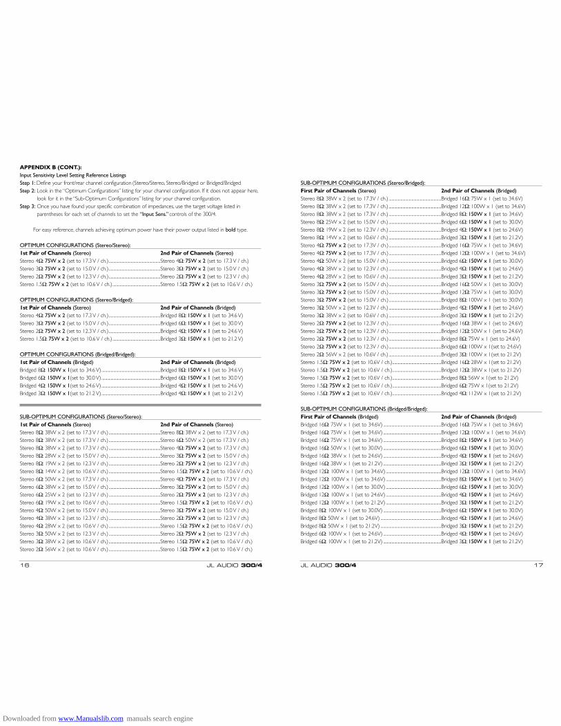
SUB-OPTIMUM CONFIGURATIONS (Stereo/Bridged):First Pair of Channels (Stereo) 2nd Pair of Channels (Bridged)Stereo 8Ω: 38W x 2 (set to 17.3V / ch.) .........................................................Bridged 16Ω: 75W x 1 (set to 34.6V)Stereo 8Ω: 38W x 2 (set to 17.3V / ch.) .........................................................Bridged 12Ω: 100W x 1 (set to 34.6V)Stereo 8Ω: 38W x 2 (set to 17.3V / ch.) .........................................................Bridged 8Ω: 150W x 1 (set to 34.6V)Stereo 8Ω: 25W x 2 (set to 15.0V / ch.) .........................................................Bridged 6Ω: 150W x 1 (set to 30.0V)Stereo 8Ω: 19W x 2 (set to 12.3V / ch.) .........................................................Bridged 4Ω: 150W x 1 (set to 24.6V)Stereo 8Ω: 14W x 2 (set to 10.6V / ch.) .........................................................Bridged 3Ω: 150W x 1 (set to 21.2V)Stereo 4Ω: 75W x 2 (set to 17.3V / ch.).........................................................Bridged 16Ω: 75W x 1 (set to 34.6V)Stereo 4Ω: 75W x 2 (set to 17.3V / ch.).........................................................Bridged 12Ω: 100W x 1 (set to 34.6V)Stereo 4Ω: 50W x 2 (set to 15.0V / ch.) .........................................................Bridged 6Ω: 150W x 1 (set to 30.0V)Stereo 4Ω: 38W x 2 (set to 12.3V / ch.) .........................................................Bridged 4Ω: 150W x 1 (set to 24.6V)Stereo 4Ω: 28W x 2 (set to 10.6V / ch.) .........................................................Bridged 3Ω: 150W x 1 (set to 21.2V)Stereo 3Ω: 75W x 2 (set to 15.0V / ch.).........................................................Bridged 16Ω: 50W x 1 (set to 30.0V)Stereo 3Ω: 75W x 2 (set to 15.0V / ch.).........................................................Bridged 12Ω: 75W x 1 (set to 30.0V)Stereo 3Ω: 75W x 2 (set to 15.0V / ch.).........................................................Bridged 8Ω: 100W x 1 (set to 30.0V)Stereo 3Ω: 50W x 2 (set to 12.3V / ch.) .........................................................Bridged 4Ω: 150W x 1 (set to 24.6V)Stereo 3Ω: 38W x 2 (set to 10.6V / ch.) .........................................................Bridged 3Ω: 150W x 1 (set to 21.2V)Stereo 2Ω: 75W x 2 (set to 12.3V / ch.).........................................................Bridged 16Ω: 38W x 1 (set to 24.6V)Stereo 2Ω: 75W x 2 (set to 12.3V / ch.).........................................................Bridged 12Ω: 50W x 1 (set to 24.6V)Stereo 2Ω: 75W x 2 (set to 12.3V / ch.).........................................................Bridged 8Ω: 75W x 1 (set to 24.6V)Stereo 2Ω: 75W x 2 (set to 12.3V / ch.).........................................................Bridged 6Ω: 100W x 1(set to 24.6V)Stereo 2Ω: 56W x 2 (set to 10.6V / ch.) .........................................................Bridged 3Ω: 100W x 1(set to 21.2V)Stereo 1.5Ω: 75W x 2 (set to 10.6V / ch.).....................................................Bridged 16Ω: 28W x 1(set to 21.2V)Stereo 1.5Ω: 75W x 2 (set to 10.6V / ch.).....................................................Bridged 12Ω: 38W x 1(set to 21.2V)Stereo 1.5Ω: 75W x 2 (set to 10.6V / ch.).....................................................Bridged 8Ω: 56W x 1(set to 21.2V)Stereo 1.5Ω: 75W x 2 (set to 10.6V / ch.).....................................................Bridged 6Ω: 75W x 1(set to 21.2V)Stereo 1.5Ω: 75W x 2 (set to 10.6V / ch.).....................................................Bridged 4Ω: 112W x 1(set to 21.2V)
SUB-OPTIMUM CONFIGURATIONS (Bridged/Bridged):First Pair of Channels (Bridged) 2nd Pair of Channels (Bridged)Bridged 16Ω: 75W x 1 (set to 34.6V) ...............................................................Bridged 16Ω: 75W x 1 (set to 34.6V)Bridged 16Ω: 75W x 1 (set to 34.6V) ...............................................................Bridged 12Ω: 100W x 1 (set to 34.6V)Bridged 16Ω: 75W x 1 (set to 34.6V) ...............................................................Bridged 8Ω: 150W x 1 (set to 34.6V)Bridged 16Ω: 50W x 1 (set to 30.0V) ...............................................................Bridged 6Ω: 150W x 1 (set to 30.0V)Bridged 16Ω: 38W x 1 (set to 24.6V) ...............................................................Bridged 4Ω: 150W x 1 (set to 24.6V)Bridged 16Ω: 38W x 1 (set to 21.2V) ...............................................................Bridged 3Ω: 150W x 1 (set to 21.2V)Bridged 12Ω: 100W x 1 (set to 34.6V) ............................................................Bridged 12Ω: 100W x 1 (set to 34.6V)Bridged 12Ω: 100W x 1 (set to 34.6V) ............................................................Bridged 8Ω: 150W x 1 (set to 34.6V)Bridged 12Ω: 100W x 1 (set to 30.0V) ............................................................Bridged 6Ω: 150W x 1 (set to 30.0V)Bridged 12Ω: 100W x 1 (set to 24.6V) ............................................................Bridged 4Ω: 150W x 1 (set to 24.6V)Bridged 12Ω: 100W x 1 (set to 21.2V) ............................................................Bridged 3Ω: 150W x 1 (set to 21.2V)Bridged 8Ω: 100W x 1 (set to 30.0V) ...............................................................Bridged 6Ω: 150W x 1 (set to 30.0V)Bridged 8Ω: 50W x 1 (set to 24.6V) ..................................................................Bridged 4Ω: 150W x 1 (set to 24.6V)Bridged 8Ω: 50W x 1 (set to 21.2V) ..................................................................Bridged 3Ω: 150W x 1 (set to 21.2V)Bridged 6Ω: 100W x 1 (set to 24.6V) ...............................................................Bridged 4Ω: 150W x 1 (set to 24.6V)Bridged 6Ω: 100W x 1 (set to 21.2V) ...............................................................Bridged 3Ω: 150W x 1 (set to 21.2V)
16 JL AUDIO 300/4
APPENDIX B (CONT.):Input Sensitivity Level Setting Reference Listings Step 1: Define your front/rear channel configuration (Stereo/Stereo, Stereo/Bridged or Bridged/BridgedStep 2: Look in the “Optimum Configurations” listing for your channel configuration. If it does not appear here,
look for it in the “Sub-Optimum Configurations” listing for your channel configuration.Step 3: Once you have found your specific combination of impedances, use the target voltage listed in
parentheses for each set of channels to set the “Input Sens.” controls of the 300/4.
For easy reference, channels achieving optimum power have their power output listed in bold type.
OPTIMUM CONFIGURATIONS (Stereo/Stereo):1st Pair of Channels (Stereo) 2nd Pair of Channels (Stereo)Stereo 4Ω: 75W x 2 (set to 17.3 V / ch.)........................................................Stereo 4Ω: 75W x 2 (set to 17.3 V / ch.)Stereo 3Ω: 75W x 2 (set to 15.0 V / ch.)........................................................Stereo 3Ω: 75W x 2 (set to 15.0 V / ch.)Stereo 2Ω: 75W x 2 (set to 12.3 V / ch.)........................................................Stereo 2Ω: 75W x 2 (set to 12.3 V / ch.)Stereo 1.5Ω: 75W x 2 (set to 10.6 V / ch.)....................................................Stereo 1.5Ω: 75W x 2 (set to 10.6 V / ch.)
OPTIMUM CONFIGURATIONS (Stereo/Bridged):1st Pair of Channels (Stereo) 2nd Pair of Channels (Bridged)Stereo 4Ω: 75W x 2 (set to 17.3 V / ch.)........................................................Bridged 8Ω: 150W x 1 (set to 34.6 V)Stereo 3Ω: 75W x 2 (set to 15.0 V / ch.)........................................................Bridged 6Ω: 150W x 1 (set to 30.0 V)Stereo 2Ω: 75W x 2 (set to 12.3 V / ch.)........................................................Bridged 4Ω: 150W x 1 (set to 24.6 V)Stereo 1.5Ω: 75W x 2 (set to 10.6 V / ch.)....................................................Bridged 3Ω: 150W x 1 (set to 21.2 V)
OPTIMUM CONFIGURATIONS (Bridged/Bridged):1st Pair of Channels (Bridged) 2nd Pair of Channels (Bridged)Bridged 8Ω: 150W x 1(set to 34.6 V)................................................................Bridged 8Ω: 150W x 1 (set to 34.6 V)Bridged 6Ω: 150W x 1(set to 30.0 V)................................................................Bridged 6Ω: 150W x 1 (set to 30.0 V)Bridged 4Ω: 150W x 1(set to 24.6 V)................................................................Bridged 4Ω: 150W x 1 (set to 24.6 V)Bridged 3Ω: 150W x 1(set to 21.2 V)................................................................Bridged 4Ω: 150W x 1 (set to 21.2 V)
SUB-OPTIMUM CONFIGURATIONS (Stereo/Stereo):1st Pair of Channels (Stereo) 2nd Pair of Channels (Stereo)Stereo 8Ω: 38W x 2 (set to 17.3 V / ch.) ........................................................Stereo 8Ω: 38W x 2 (set to 17.3 V / ch.)Stereo 8Ω: 38W x 2 (set to 17.3 V / ch.) ........................................................Stereo 6Ω: 50W x 2 (set to 17.3 V / ch.)Stereo 8Ω: 38W x 2 (set to 17.3 V / ch.) ........................................................Stereo 4Ω: 75W x 2 (set to 17.3 V / ch.)Stereo 8Ω: 28W x 2 (set to 15.0 V / ch.) ........................................................Stereo 3Ω: 75W x 2 (set to 15.0 V / ch.)Stereo 8Ω: 19W x 2 (set to 12.3 V / ch.) ........................................................Stereo 2Ω: 75W x 2 (set to 12.3 V / ch.)Stereo 8Ω: 14W x 2 (set to 10.6 V / ch.) ........................................................Stereo 1.5Ω: 75W x 2 (set to 10.6 V / ch.)Stereo 6Ω: 50W x 2 (set to 17.3 V / ch.) ........................................................Stereo 4Ω: 75W x 2 (set to 17.3 V / ch.)Stereo 6Ω: 38W x 2 (set to 15.0 V / ch.) ........................................................Stereo 3Ω: 75W x 2 (set to 15.0 V / ch.)Stereo 6Ω: 25W x 2 (set to 12.3 V / ch.) ........................................................Stereo 2Ω: 75W x 2 (set to 12.3 V / ch.)Stereo 6Ω: 19W x 2 (set to 10.6 V / ch.) ........................................................Stereo 1.5Ω: 75W x 2 (set to 10.6 V / ch.)Stereo 4Ω: 50W x 2 (set to 15.0 V / ch.) ........................................................Stereo 3Ω: 75W x 2 (set to 15.0 V / ch.) Stereo 4Ω: 38W x 2 (set to 12.3 V / ch.) ........................................................Stereo 2Ω: 75W x 2 (set to 12.3 V / ch.)Stereo 4Ω: 28W x 2 (set to 10.6 V / ch.) ........................................................Stereo 1.5Ω: 75W x 2 (set to 10.6 V / ch.)Stereo 3Ω: 50W x 2 (set to 12.3 V / ch.) ........................................................Stereo 2Ω: 75W x 2 (set to 12.3 V / ch.)Stereo 3Ω: 38W x 2 (set to 10.6 V / ch.) ........................................................Stereo 1.5Ω: 75W x 2 (set to 10.6 V / ch.)Stereo 2Ω: 56W x 2 (set to 10.6 V / ch.) ........................................................Stereo 1.5Ω: 75W x 2 (set to 10.6 V / ch.)
Downloaded from www.Manualslib.com manuals search engine

JL AUDIO 300/4 19
“MY AMPLIFIER TURNS ON, BUT THERE IS NO OUTPUT”Check the input signal using an AC voltmeter to measure the
voltage from the source unit while an appropriate test toneis played through the source unit (disconnect the RCAcables from the amplifier prior to this test).The frequencyused should be in the range that is to amplified by thechannels being tested (example: 50 Hz for a sub bassamplifier channel and 1 kHz for a full range amplifierchannel). A steady voltage should be present at the outputof the RCA cables. If you are receiving a sufficient voltage(between 0.2 and 8.0-volts), check to ensure that thespeaker wires are making a good connection with the metalinside the amplifier. The connectors are designed to acceptup to an 8 AWG wire. If you are using significantly smallerwire (14 AWG or smaller), you may have difficulty makingan adequate connection. In this case, you may find itnecessary to “fold” the wire over once (or twice!) so as tomake a solid connection. Make sure to strip the wire toallow for a sufficient connection with the input or output of the amplifier.
Check the output of the amplifier. Using the procedure explained inthe previous check item (after plugging the RCA cables backinto the amplifier) test for output at the speaker outputs of theamplifier. Unless you enjoy test tones at high levels, it is a goodidea to remove the speaker wires from the amplifier whiledoing this. Turn the volume up approximately half way.5 volts or more should be measured at the speaker outputs.This output level can vary greatly between amplifiers but itshould not be in the millivolt range with the source unit at halfvolume. If you are reading sufficient voltage, check your speakerconnections as explained above.
“MY AMPLIFIER’S OUTPUT FLUCTUATES WHEN I TAP ON IT OR HIT A BUMP”Check the connections to the amplifier. Make sure that the insulation
for all wires has been stripped back far enough to allow agood contact area inside the amplifier terminal.
Check the RCA connectors to ensure that both the center pin andthe outer shield are making good contact with the input jackson the amplifier.
“HOW DO I PROPERLY SET THE INPUT SENSITIVITY ON MY AMPLIFIER”Please refer to Appendix B (page 14) to set the input sensitivity for
maximum, low-distortion output.
“MY AMPLIFIER DOESN’T TURN ON”Check to make sure there is +12V at the “Remote” connection of
the amplifier. In some cases, the turn-on lead from the sourceunit is insufficient to turn on multiple devices and the use of arelay is required. To test for this problem, jump the “+12V”wire to the “Remote” terminal to see if the amplifier turns on.If this does not work, proceed to the next step.
Check the fuse, not just visually, but with a continuity meter. It ispossible for a fuse to have poor internal connections thatcannot be found by visual inspection. It is best to take thefuse out of the holder for testing. If no problem is foundwith the fuse, inspect the fuse-holder.
“I GET A DISTORTED / ATTENUATED SOUND COMING OUT OF THE SPEAKER(S)”Check the speaker wires for a possible short, either between the
positive and negative or between a speaker lead and thevehicle’s chassis ground. If a short is present you willexperience distorted and/or attenuated output.The “Low Ω” light may also illuminate in this situation. It may behelpful to disconnect the speaker wires from the amplifierand use a different set of wires connected to a test speaker.
Check the nominal load impedance to verify that each channel of the amplifier is driving a load between 1.5 - 4Ω(3 - 8Ω bridged).
Check the input signal and input signal cables to make sure signal ispresent at the “Front Input Section” and “Rear InputSection” and the cables are not pinched or loose. It may behelpful to try a different set of cables and/or a different signalsource to be sure.
“MY AMPLIFIER SHUTS OFF ONCE IN A WHILE, USUALLY AT HIGHER VOLUMES”Check your voltage source and grounding point.The R.I.P.S. power
supply is rated to operate with source voltages between 11 - 14.5V. Shutdown problems at higher levels can occurwhen the charging system voltage drops below 10 volts.Thesedips can be of very short duration making them extremelydifficult to detect with a common DC voltmeter.To ensureproper voltage, inspect all wiring and termination points. It isalso a good idea to improve the vehicle’s factory ground wireand termination point. Grounding problems are the leadingcause of mis-diagnosed amplifier failures.
18 JL AUDIO 300/4
APPENDIX C: TROUBLE SHOOTING
Downloaded from www.Manualslib.com manuals search engine
JL AUDIO 300/4 21
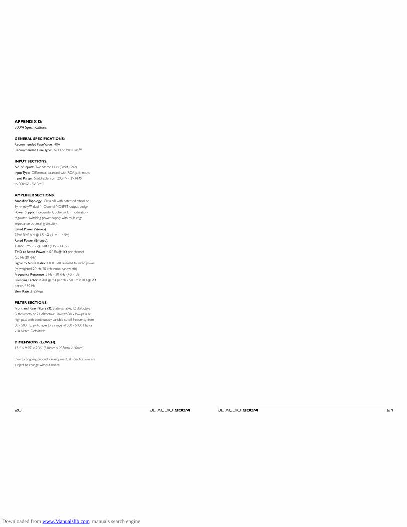
APPENDIX D:300/4 Specifications
GENERAL SPECIFICATIONS:
Recommended Fuse Value: 40A
Recommended Fuse Type: AGU or MaxiFuse™
INPUT SECTIONS:
No. of Inputs: Two Stereo Pairs (Front, Rear)
Input Type: Differential-balanced with RCA jack inputs
Input Range: Switchable from 200mV - 2V RMS
to 800mV - 8V RMS
AMPLIFIER SECTIONS:
Amplifier Topology: Class AB with patented Absolute
Symmetry™ dual N-Channel MOSFET output design
Power Supply: Independent, pulse width modulation-
regulated switching power supply with multistage
impedance optimizing circuitry.
Rated Power (Stereo):
75W RMS x 4 @ 1.5-4Ω (11V - 14.5V)
Rated Power (Bridged):
150W RMS x 2 @ 3-8Ω (11V - 14.5V)
THD at Rated Power: <0.03% @ 4Ω per channel
(20 Hz-20 kHz)
Signal to Noise Ratio: >108.5 dB referred to rated power
(A-weighted, 20 Hz-20 kHz noise bandwidth)
Frequency Response: 5 Hz - 30 kHz (+0, -1dB)
Damping Factor: >200 @ 4Ω per ch. / 50 Hz, >100 @ 2Ωper ch. / 50 Hz
Slew Rate: ± 25V/µs
FILTER SECTIONS:
Front and Rear Filters (2): State-variable, 12 dB/octave
Butterworth or 24 dB/octave Linkwitz-Riley low-pass or
high-pass with continuously variable cutoff frequency from
50 - 500 Hz, switchable to a range of 500 - 5000 Hz, via
x10 switch. Defeatable.
DIMENSIONS (LxWxH):
13.4" x 9.25" x 2.36" (340mm x 235mm x 60mm)
Due to ongoing product development, all specifications are
subject to change without notice.
20 JL AUDIO 300/4
Downloaded from www.Manualslib.com manuals search engine
JL AUDIO 300/4 2322 JL AUDIO 300/4
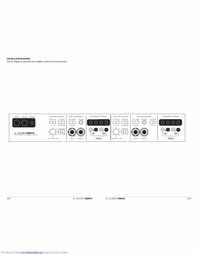
INSTALLATION NOTES:Use this diagram to document your amplifier’s switch and control positions.
Downloaded from www.Manualslib.com manuals search engine
LIMITED WARRANTY - AMPLIFIERS (USA)
JL AUDIO warrants this product to be free of defects in materials and workmanship for a period of ninety(90) days from the original date of purchase.The warranty term is extended to two (2) years if installation isperformed or approved by an authorized JL AUDIO dealer (proof of installation or approval required onpurchase receipt).
This warranty is not transferrable and applies only to the original purchaser from an authorized JL AUDIOdealer. Should service be necessary under this warranty for any reason due to manufacturing defect ormalfunction, JL AUDIO will (at its discretion), repair or replace the defective product with new or remanufacturedproduct at no charge. Damage caused by the following is not covered under warranty: accident, misuse, abuse,product modification or neglect, failure to follow installation instructions, unauthorized repair attempts,misrepresentations by the seller.This warranty does not cover incidental or consequential damages and does notcover the cost of removing or reinstalling the unit(s). Cosmetic damage due to accident or normal wear and tearis not covered under warranty.
Warranty is void if the product’s serial number has been removed or defaced.Any applicable implied warranties are limited in duration to the period of the express warranty as provided
herein beginning with the date of the original purchase at retail, and no warranties, whether express or implied,shall apply to this product thereafter. Some states do not allow limitations on implied warranties, therefore theseexclusions may not apply to you.This warranty gives you specific legal rights, and you may also have other rightswhich vary from state to state.
If you need service on your JL AUDIO product:All warranty returns should be sent to JL AUDIO ’s Amplifier Service Facility freight-prepaid through an
authorized JL AUDIO dealer and must be accompanied by proof of purchase (a copy of the original sales receipt).Direct returns from consumers or non-authorized dealers will be refused unless specifically authorized by JL AUDIO with a valid return authorization number.
Warranty expiration on products returned without proof of purchase will be determined from themanufacturing date code. Coverage may be invalidated as this date is previous to purchase date. Non-defectiveitems received will be returned freight-collect. Customer is responsible for shipping charges and insurance insending the product to JL AUDIO. Freight damage on returns is not covered under warranty.
For Service Information in the U.S.A. please call:JL Audio customer service: (954) 443-1100
during normal business hours (9:00 AM – 5:30 PM Eastern Time)JL Audio, Inc
10369 North Commerce Pkwy.Miramar, FL 33025
(do not send product for repair to this address)
International Warranties:Products purchased outside the United States of America are covered only
by that country’s distributor and not by JL Audio, Inc.
JL3004MAN-04-2003
Absolute Symmetry™ Class AB Amplifier Circuit is covered by U.S. Patent #6,294,959 and ispending in the countries listed below. Austria,Belgium,Brazil,Canada,China,France,Germany, Indonesia,Italy, Japan, Republic of Korea, Mexico, Netherlands, Norway, Russian Federation, Singapore, Sweden,Switzerland, United Kingdom, and all other PCT countries.
Downloaded from www.Manualslib.com manuals search engine