Embed Size (px)
Citation preview

7/23/2019 Manual H81M
http://slidepdf.com/reader/full/manual-h81m 1/74
M o
t h
e r b
o a
r dH81M-PLUS

7/23/2019 Manual H81M
http://slidepdf.com/reader/full/manual-h81m 2/74
ii
E8448
First Edition V1June 2013
Copyright © 2013 ASUSTeK COMPUTER INC. All Rights Reserved.
No part of this manual, including the products and software described in it, may be reproduced,transmitted, transcribed, stored in a retrieval system, or translated into any language in any form or by anymeans, except documentation kept by the purchaser for backup purposes, without the express writtenpermission of ASUSTeK COMPUTER INC. (“ASUS”).
Product warranty or service will not be extended if: (1) the product is repaired, modied or altered, unlesssuch repair, modication of alteration is authorized in writing by ASUS; or (2) the serial number of theproduct is defaced or missing.
ASUS PROVIDES THIS MANUAL “AS IS” WITHOUT WARRANTY OF ANY KIND, EITHER EXPRESSOR IMPLIED, INCLUDING BUT NOT LIMITED TO THE IMPLIED WARRANTIES OR CONDITIONS OFMERCHANTABILITY OR FITNESS FOR A PARTICULAR PURPOSE. IN NO EVENT SHALL ASUS, ITSDIRECTORS, OFFICERS, EMPLOYEES OR AGENTS BE LIABLE FOR ANY INDIRECT, SPECIAL,
INCIDENTAL, OR CONSEQUENTIAL DAMAGES (INCLUDING DAMAGES FOR LOSS OF PROFITS,LOSS OF BUSINESS, LOSS OF USE OR DATA, INTERRUPTION OF BUSINESS AND THE LIKE),EVEN IF ASUS HAS BEEN ADVISED OF THE POSSIBILITY OF SUCH DAMAGES ARISING FROM ANYDEFECT OR ERROR IN THIS MANUAL OR PRODUCT.
SPECIFICATIONS AND INFORMATION CONTAINED IN THIS MANUAL ARE FURNISHED FORINFORMATIONAL USE ONLY, AND ARE SUBJECT TO CHANGE AT ANY TIME WITHOUT NOTICE,AND SHOULD NOT BE CONSTRUED AS A COMMITMENT BY ASUS. ASUS ASSUMES NORESPONSIBILITY OR LIABILITY FOR ANY ERRORS OR INACCURACIES THAT MAY APPEAR IN THISMANUAL, INCLUDING THE PRODUCTS AND SOFTWARE DESCRIBED IN IT.
Products and corporate names appearing in this manual may or may not be registered trademarks orcopyrights of their respective companies, and are used only for identication or explanation and to theowners’ benet, without intent to infringe.
Offer to Provide Source Code of Certain SoftwareThis product contains copyrighted software that is licensed under the General Public License (“GPL”),under the Lesser General Public License Version (“LGPL”) and/or other Free Open Source SoftwareLicenses. Such software in this product is distributed without any warranty to the extent permitted by theapplicable law. Copies of these licenses are included in this product.
Where the applicable license entitles you to the source code of such software and/or other additional data,you may obtain it for a period of three years after our last shipment of the product, either
(1) for free by downloading it from http://support.asus.com/download
or
(2) for the cost of reproduction and shipment, which is dependent on the preferred carrier and the locationwhere you want to have it shipped to, by sending a request to:
ASUSTeK Computer Inc.
Legal Compliance Dept.
15 Li Te Rd.,
Beitou, Taipei 112
Taiwan
In your request please provide the name, model number and version, as stated in the About Box of theproduct for which you wish to obtain the corresponding source code and your contact details so that wecan coordinate the terms and cost of shipment with you.
The source code will be distributed WITHOUT ANY WARRANTY and licensed under the same license asthe corresponding binary/object code.
This offer is valid to anyone in receipt of this information.
ASUSTeK is eager to duly provide complete source code as required under various Free Open SourceSoftware licenses. If however you encounter any problems in obtaining the full corresponding sourcecode we would be much obliged if you give us a notication to the email address [email protected], statingthe product and describing the problem (please DO NOT send large attachments such as source codearchives, etc. to this email address).

7/23/2019 Manual H81M
http://slidepdf.com/reader/full/manual-h81m 3/74
iii
Contents
Safety information ...................................................................................... iv
About this guide ......................................................................................... iv
Package contents ....................................................................................... vi
H81M-PLUS specications summary ....................................................... vi
Product introduction
1.1 Before you proceed ..................................................................... 1-1
1.2 Motherboard overview ................................................................. 1-1
1.3 Central Processing Unit (CPU) ................................................... 1-3
1.4 System memory ........................................................................... 1-7
1.5 Expansion slots............................................................................ 1-91.6 Jumpers ...................................................................................... 1-10
1.7 Connectors ................................................................................. 1-12
1.8 Onboard LEDs ............................................................................ 1-19
1.9 Software support ........................................................................ 1-20
BIOS information
2.1 Managing and updating your BIOS ............................................ 2-1
2.2 BIOS setup program .................................................................... 2-6
2.3 My Favorites ............................................................................... 2-10
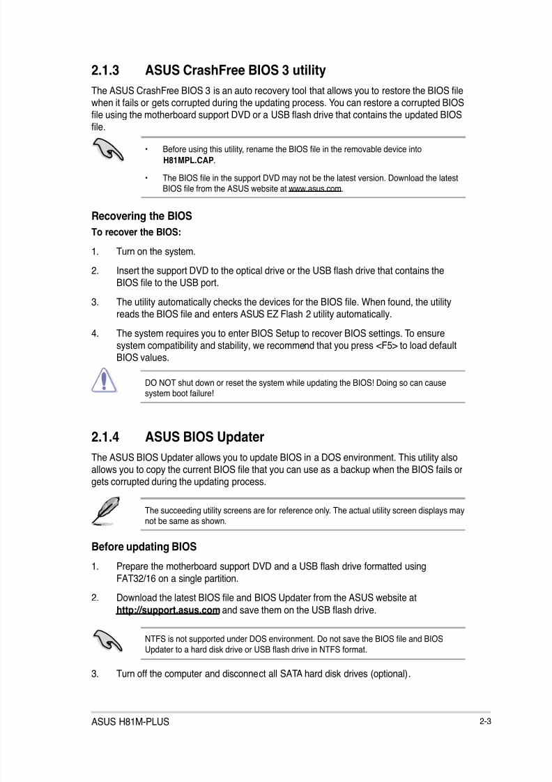
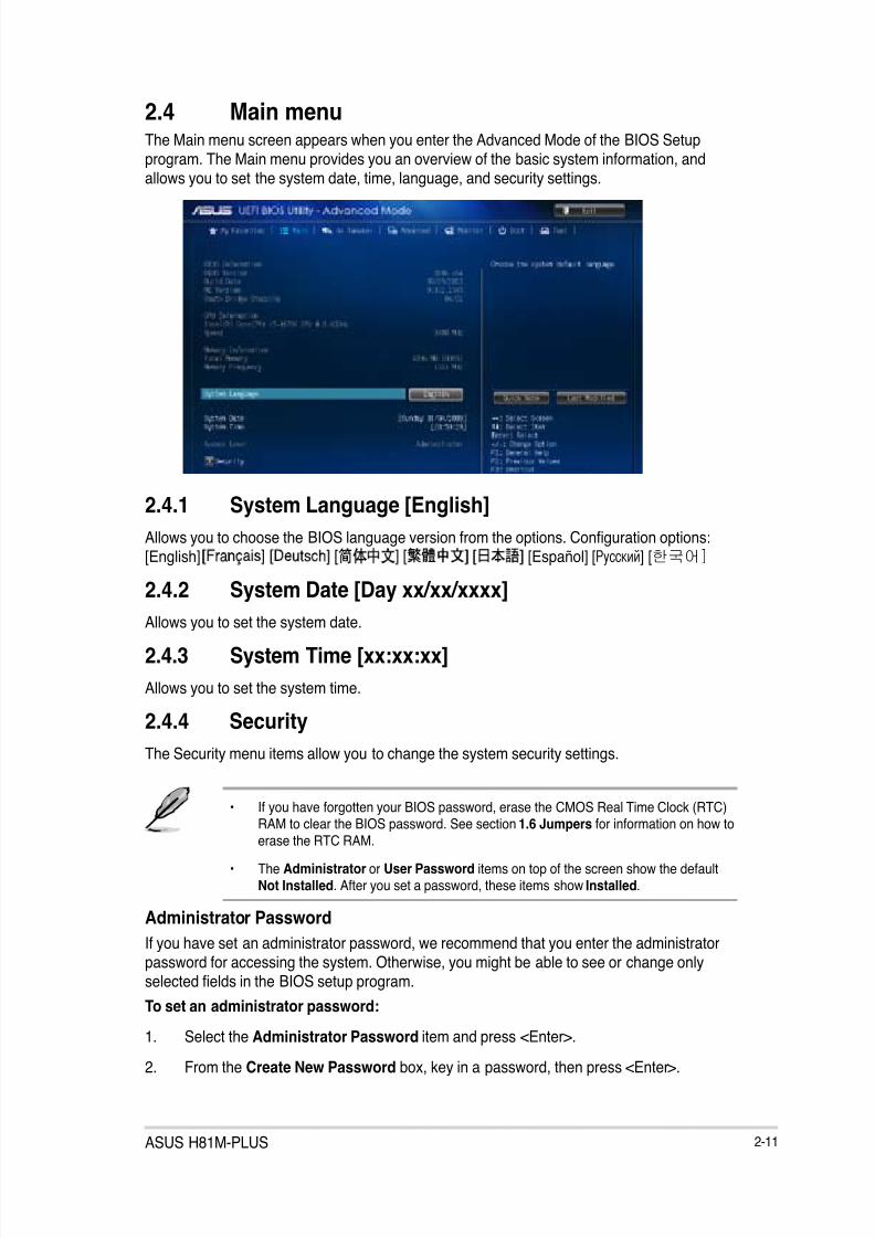
2.4 Main menu .................................................................................. 2-11
2.5 Ai Tweaker menu ........................................................................ 2-13
2.6 Advanced menu ......................................................................... 2-24
2.7 Monitor menu ............................................................................. 2-33
2.8 Boot menu .................................................................................. 2-35
2.9 Tools menu ................................................................................. 2-412.10 Exit menu .................................................................................... 2-42
Appendices
Notices .......................................................................................................A-1
ASUS contact information .......................................................................A-3

7/23/2019 Manual H81M
http://slidepdf.com/reader/full/manual-h81m 4/74
iv
Safety information
Electrical safety
To prevent electrical shock hazard, disconnect the power cable from the electrical outletbefore relocating the system.
When adding or removing devices to or from the system, ensure that the power cablesfor the devices are unplugged before the signal cables are connected. If possible,disconnect all power cables from the existing system before you add a device.
Before connecting or removing signal cables from the motherboard, ensure that allpower cables are unplugged.
Seek professional assistance before using an adapter or extension cord. These devicescould interrupt the grounding circuit.
Ensure that your power supply is set to the correct voltage in your area. If you are notsure about the voltage of the electrical outlet you are using, contact your local power
company.
If the power supply is broken, do not try to x it by yourself. Contact a qualied servicetechnician or your retailer.
Operation safety
Before installing the motherboard and adding components, carefully read all the manualsthat came with the package.
Before using the product, ensure all cables are correctly connected and the powercables are not damaged. If you detect any damage, contact your dealer immediately.
To avoid short circuits, keep paper clips, screws, and staples away from connectors,slots, sockets and circuitry.
Avoid dust, humidity, and temperature extremes. Do not place the product in any areawhere it may be exposed to moisture.
Place the product on a stable surface.
If you encounter technical problems with the product, contact a qualied servicetechnician or your retailer.
About this guideThis user guide contains the information you need when installing and conguring themotherboard.
How this guide is organized
This guide contains the following parts:
• Chapter 1: Product introduction
This chapter describes the features of the motherboard and the new technology it
supports. It includes descriptions of the switches, jumpers, and connectors on themotherboard.
• Chapter 2: BIOS information
This chapter discusses changing system settings through the BIOS Setup menus.
Detailed descriptions fo the BIOS parameters are also provided.
•
•
•
•
•
•
•
•
•
•
•
•

7/23/2019 Manual H81M
http://slidepdf.com/reader/full/manual-h81m 5/74
v
Where to nd more information
Refer to the following sources for additional information and for product and softwareupdates.
1. ASUS websites
The ASUS website provides updated information on ASUS hardware and softwareproducts. Refer to the ASUS contact information.
2. Optional documentation
Your product package may include optional documentation, such as warranty yers,that may have been added by your dealer. These documents are not part of thestandard package.
Conventions used in this guideTo ensure that you perform certain tasks properly, take note of the following symbols usedthroughout this manual.
DANGER/WARNING: Information to prevent injury to yourself whencompleting a task.
CAUTION: Information to prevent damage to the components whencompleting a task
IMPORTANT: Instructions that you MUST follow to complete a task.
NOTE: Tips and additional information to help you complete a task.
Typography
Bold text Indicates a menu or an item to select.
Italics Used to emphasize a word or a phrase.
<Key> Keys enclosed in the less-than and greater-than signmeans that you must press the enclosed key.
Example: <Enter> means that you must press the Enter orReturn key.
<Key1> + <Key2> + <Key3> If you must press two or more keys simultaneously, the keynames are linked with a plus sign (+).

7/23/2019 Manual H81M
http://slidepdf.com/reader/full/manual-h81m 6/74
vi
H81M-PLUS specications summary
(continued on the next page)
CPU LGA1150 socket for 4th Generation Intel® CoreTM i7/i5/i3, Pentium®, Celeron® Processors
Supports Intel® 22nm CPU
Supports Intel® Turbo Boost Technology 2.0*
* The Intel® Turbo Boost Technology 2.0 support depends on the CPU types.
** Refer to www.asus.com for Intel® CPU support list.
Chipset Intel® H81 Express Chipset
Memory 2 x DIMM, max. 16GB, DDR3 1600 / 1333 / 1066 MHz, non-ECC, un-bufferedmemory*
Dual-channel memory architecture
Supports Intel® Extreme Memory Prole (XMP)
* Hyper DIMM support is subject to the physical characteristics of individual CPUs.Please refer to the Memory QVL (Qualied Vendors List) for details.
** Refer to www.asus.com for the latest Memory QVL (Qualied Vendors List).
*** Due to Intel® chipset limitation, the DDR3 1600MHz and higher memory modules onXMP mode will run at the maximum transfer rate of DDR3 1600MHz.
Graphics Integrated graphics processor - Intel® HD Graphics support
Multi-VGA output support: RGB, DVI-D, and HDMI ports
- Supports HDMI with max. resolution of 4096 x 2160 @24Hz / 2560 x 1600
@60Hz - Supports DVI-D with max.resolution of 1920 x 1200 @60Hz
- Supports RGB with max. resolution of 1920 x 1200 @60Hz
Maximum shared memory of 1024 MB
Expansionslots
1 x PCI Express x16 slot (at x16 mode, yellow)
3 x PCI Express x1 slots
Storage Intel® H81 Express Chipset:
- 2 x Serial ATA 6.0 Gb/s connector (yellow)
- 2 x Serial ATA 3.0 Gb/s connector (dark brown)
- Support Intel® Rapid Start Technology* and Intel® Smart Connect
Technology*** Due to the limitation of the Intel H81 chipset, Intel Rapid Start Technology can be
congured only from the BIOS Setup program..
* These functions will work depending on the CPU installed.
LAN Realtek 8111G Gigabit LAN controller
Package contentsCheck your motherboard package for the following items.
Motherboard ASUS H81M-PLUS motherboard
Cables 2 x Serial ATA 6.0 Gb/s cables
Accessories 1 x I/O Shield
Application DVD Support DVD
Documentation User Guide
If any of the above items is damaged or missing, contact your retailer.

7/23/2019 Manual H81M
http://slidepdf.com/reader/full/manual-h81m 7/74
vii
H81M-PLUS specications summary
Audio Realtek® ALC887 8-channel Audio CODEC
- Supports jack-detection, multi-streaming, front panel jack-restasking
* Use a chassis with HD audio module in the front panel to support an 8-channelaudio output.
USB Intel® H81 Express Chipset - supports ASUS USB 3.0 Boost
- 2 x USB 3.0/2.0 ports at mid-board for front panel support
- 8 x USB2.0/1.1 ports (4 ports at midboard, 4 ports at back panel)
ASMedia® ASM1042 USB3.0 Controller - supports ASUS USB 3.0 BoostUASP Mode
- 2 x USB 3.0/2.0 ports at rear panel (blue)
ASUS uniquefeatures
ASUS 5X Protection - ASUS motherboards safeguard your PC with 5X Protection:
DIGI+VRM, DRAM Fuse, ESD Guards, High-quality 5K-Hour SolidCapacitors, and Stainless Steel Back I/O to ensure the best quality,
reliability, and durability
ASUS DIGI+ VRM - ASUS DIGI+ VRM: Digital Power Design for CPU
- ASUS 3 Phase Power Design
- ASUS CPU power utility
ASUS DRAM Fuse - Enhanced DRAM overcurrent protection and short circuit damage
prevention
ASUS ESD Guards
- Ehanced ESD protection
ASUS High-quality 5K-Hour Solid Capacitors
- 2.5x Long Lifespan with excellent durability
ASUS Stainless Steel Back I/O - 3x More durable corrosion-resistant coating
ASUS Exclusive Features: - ASUS EPU
- ASUS Network iControl
- ASUS USB 3.0 Boost
- ASUS Ai Charger+ - ASUS GPU Boost
- ASUS AI Suite 3
- ASUS Anti-surge
ASUS Quiet Thermal Solution: - ASUS Fan Xpert
- ASUS Fanless Design: Stylish Heatsink solution
ASUS EZ DIY: - ASUS UEFI BIOS EZ Mode featuring friendly graphical user interface
- ASUS CrashFree BIOS 3 - ASUS EZ Flash 2
ASUS Q-Design - ASUS Q-Slot
(continued on the next page)

7/23/2019 Manual H81M
http://slidepdf.com/reader/full/manual-h81m 8/74
viii
H81M-PLUS specications summary
Rear panel I/Oports
1 x PS/2 keyboard port (purple)
1 x PS/2 mouse port (green)
1 x DVI port
1 x RGB port
1 x HDMI port
1 x LAN (RJ-45) port
2 x USB 3.0/2.0 ports
4 x USB 2.0/1.1 ports
3 x Audio jacks support 8-channel audio output
Internalconnectors/switches/buttons
1 x USB 3.0/2.0 connector supports additional 2 USB 3.0/2.0 ports (19-pin)
2 x USB 2.0/1.1 connectors support additional 4 USB 2.0/1.1 ports
2 x SATA 6.0 Gb/s connectors
2 x SATA 3.0 Gb/s connectors
1 x CLRTC jumper
1 x 4-pin CPU fan connector
1 x 4-pin Chassis fan connectors
1 x Front panel audio connector (AAFP)
1 x System panel connector
1 x Speaker connector
1 x S/PDIF Header
1 x 24-pin EATX power connector
1 x 4-pin EATX 12V power connector
BIOS features 64 Mb Flash ROM, UEFI AMI BIOS, PnP, DMI v2.0, WfM2.0, SM BIOS v2.7, ACPIv2.0a, Multi-language BIOS, ASUS EZ Flash 2, ASUS CrashFree BIOS 3, MyFavorites, Quick Note, Last Modied log, F12 PrintScreen, F3 Shortcut functionsand ASUS DRAM SPD (Serial Presence Detect) memory information
Manageability WfM 2.0, DMI 2.0, WOL by PME, PXE
Support DVD Drivers
ASUS utilities
EZ Update
Anti-virus software (OEM version)
OperatingSystemSupport
Windows® 8 / Windows® 7
Form factor uATX form factor: 9.6”x 7.2” (24.4cm x 18.3cm)
Specications are subject to change without notice.

7/23/2019 Manual H81M
http://slidepdf.com/reader/full/manual-h81m 9/74
ASUS H81M-PLUS 1-1
Product introduction 11.1 Before you proceedTake note of the following precautions before you install motherboard components or changeany motherboard settings.
• Unplug the power cord from the wall socket before touching any component.
• Before handling components, use a grounded wrist strap or touch a safely groundedobject or a metal object, such as the power supply case, to avoid damaging them dueto static electricity.
• Hold components by the edges to avoid touching the ICs on them.
• Whenever you uninstall any component, place it on a grounded antistatic pad or in thebag that came with the component.
• Before you install or remove any component, ensure that the ATX power supply isswitched off or the power cord is detached from the power supply. Failure to do somay cause severe damage to the motherboard, peripherals, or components.
1.2 Motherboard overviewBefore you install the motherboard, study the conguration of your chassis to ensure that themotherboard ts.
Unplug the power cord before installing or removing the motherboard. Failure to do so cancause you physical injury and damage to motherboard components.
1.2.1 Placement direction
When installing the motherboard, place it into the chassis in the correct orientation. The edge
with external ports goes to the rear part of the chassis as indicated in the image.
1.2.2 Screw holes
Place six screws into the holes indicated by circles to secure the motherboard to the chassis.
Do not overtighten the screws! Doing so can damage the motherboard.

7/23/2019 Manual H81M
http://slidepdf.com/reader/full/manual-h81m 10/74
1-2 Chapter 1: Product introduction
H81M-PLUS
Place this sidetowards the rear
of the chassis
1.2.3 Motherboard layout
H81M-PLUS
PCIEX16_1
PCIEX1_1
PCIEX1_2
PCIEX1_3
RTL
8111G
ASM
1442
U SB11 12 U SB91 0
AAFP
E A T X P W R
CPU_FAN
BATTERY
SuperI/O
ALC887-VD2
ASM
1042
KBMS
D V I_ V G A
64Mb
BIOS
SB_PWR
CLRTC
USBPWF
K B_
U S B P W B
SPEAKER
18.3cm(7.2in)
D D R 3 D I M M
_ A 1 ( 6 4 b i t , 2 4 0 - p i n m o d u l e )
D D R 3 D I M M
_ B 1 ( 6 4 b i t , 2 4 0 - p i n m o d u l e )
SATA3G_1 SATA3G_2
SATA6G_1 SATA6G_2
AUDIO
LAN_USB34
USB56
USB3_E12
HDMI
CHA_FAN
SPDIF_OUT
2 4 . 4 c m ( 9
. 6 i n )
L GA 1 1 5 0
DIGI+VRM
U S B 3_
1 2
Intel®
H81
ATX12V
F_PANEL
21 3 54 3
1215 11 10 91316 14
2
6
7
8

7/23/2019 Manual H81M
http://slidepdf.com/reader/full/manual-h81m 11/74
ASUS H81M-PLUS 1-3
1.2.4 Layout contents
Connectors/Jumpers/Slots/LED Page
1. Keyboard and USB device wakeup (KB_USBPWB) 1-12
2. ATX power connectors (24-pin EATXPWR, 4-pin ATX12V) 1-14
3. CPU and chassis fan connectors (4-pin CPU_FAN, 4-pin CHA_FAN) 1-16
4. Intel® LGA1150 CPU socket 1-3
5. DDR3 DIMM slots 1-7
6. USB 3.0 connector (20-1 pin USB3_12) 1-17
7. Clear RTC RAM (3-pin CLRTC) 1-10
8. Intel® H81 Serial ATA 3.0Gb/s connector (7-pin SATA3G_1~2 [dark brown]) 1-16
9. Intel® H81 Serial ATA 6.0Gb/s connector (7-pin SATA6G_1~2 [yellow]) 1-15
10. System panel connector (10-1 pin F_PANEL) 1-1811. Speaker connector (4-pin SPEAKER) 1-18
12. USB device wake-up (USBPWF) 1-11
13. USB 2.0 connectors (10-1 pin USB910, USB1112) 1-17
14. Digital audio connector (4-1 pin SPDIF_OUT) 1-14
15. Front panel audio connector (10-1 pin AAFP) 1-15
16. Onboard LED (SB_PWR) 1-19
1.3 Central Processing Unit (CPU)This motherboard comes with a surface mount LGA1150 socket designed for the Intel® 4thgeneration Core™ i7 / Core™ i5 / Core™ i3, Pentium® , Celeron® processors.
H81M-PLUS
H81M-PLUS CPU socket LGA1150

7/23/2019 Manual H81M
http://slidepdf.com/reader/full/manual-h81m 12/74
1-4 Chapter 1: Product introduction
1.3.1 Installing the CPU
1
2 3
A
B
Unplug all power cables before installing the CPU.
• Ensure that you install the correct CPU designed for the LGA1150 socket only. DO
NOT install a CPU designed for LGA1155 and LGA1156 sockets on the LGA1150socket.
• Upon purchase of the motherboard, ensure that the PnP cap is on the socket andthe socket contacts are not bent. Contact your retailer immediately if the PnP capis missing, or if you see any damage to the PnP cap/socket contacts/motherboardcomponents. ASUS will shoulder the cost of repair only if the damage is shipment/ transit-related.
• Keep the cap after installing the motherboard. ASUS will process Return MerchandiseAuthorization (RMA) requests only if the motherboard comes with the cap on theLGA1150 socket.
• The product warranty does not cover damage to the socket contacts resulting fromincorrect CPU installation/removal, or misplacement/loss/incorrect removal of the PnPcap.

7/23/2019 Manual H81M
http://slidepdf.com/reader/full/manual-h81m 13/74
ASUS H81M-PLUS 1-5
A
B
C 54
1.3.2 CPU heatsink and fan assembly installation
Apply the Thermal Interface Materialto the CPU heatsink and CPUbefore you install the heatsink andfan if necessary.

7/23/2019 Manual H81M
http://slidepdf.com/reader/full/manual-h81m 14/74
1-6 Chapter 1: Product introduction
3 4
A
B
B
A
To uninstall the CPU heatsink and fan assembly
21
To install the CPU heatsink and fan assembly
2
B
A
A
B
1

7/23/2019 Manual H81M
http://slidepdf.com/reader/full/manual-h81m 15/74
ASUS H81M-PLUS 1-7
1.4 System memory
1.4.1 Overview
This motherboard comes with two Double Data Rate 3 (DDR3) Dual Inline Memory Module
(DIMM) sockets. A DDR3 module is notched differently from a DDR or DDR2 module. DONOT install a DDR or DDR2 memory module to the DDR3 slot.
According to Intel® CPU spec, DIMM voltage below 1.65V is recommended to protect theCPU.
Channel Sockets
Channel A DIMM_A1
Channel B DIMM_B1H81M-PLUS
H81M-PLUS 240-pin DDR3 DIMM sockets
D I M M_
A 1
D I M M_
B 1
1.4.2 Memory congurations
You may install 1GB, 2GB, 4GB, and 8GB unbuffered non-ECC DDR3 DIMMs into the DIMMsockets.
• You may install varying memory sizes in Channel A and Channel B. The system mapsthe total size of the lower-sized channel for the dual-channel conguration. Any excessmemory from the higher-sized channel is then mapped for single-channel operation.
• Due to Intel® chipset limitation, DDR3 1600MHz and higher memory modules on XMPmode will run at the maximum transfer rate of DDR3 1600MHz.
• Always install DIMMs with the same CAS latency. For optimal compatibility, werecommend that you install memory modules of the same version or date code (D/C)
from the same vendor. Check with the retailer to get the correct memory modules.
• Due to the memory address limitation on 32-bit Windows® OS, when you install 4GBor more memory on the motherboard, the actual usable memory for the OS can beabout 3GB or less. For effective use of memory, we recommend that you do any of thefollowing:
- Use a maximum of 3GB system memory if you are using a 32-bit Windows® OS.
- Install a 64-bit Windows® OS if you want to install 4GB or more on themotherboard.
• This motherboard does not support DIMMs made up of 512Mb (64MB) chips or less.

7/23/2019 Manual H81M
http://slidepdf.com/reader/full/manual-h81m 16/74
1-8 Chapter 1: Product introduction
• The default memory operation frequency is dependent on its Serial Presence Detect(SPD), which is the standard way of accessing information from a memory module.Under the default state, some memory modules for overclocking may operate at a
lower frequency than the vendor-marked value. To operate at the vendor-markedor at a higher frequency, refer to section 2.5 Ai Tweaker menu for manual memoryfrequency adjustment.
• For system stability, use a more efcient memory cooling system to support a fullmemory load (2 DIMMs) or overclocking condition.
• Visit the ASUS website at: www.asus.com for the latest QVL.
1.4.3 Installing a DIMM
Unplug the power supply before adding or removing DIMMs or other system components.Failure to do so can cause severe damage to both the motherboard and the components.
1. Press the retaining clipsoutward to unlock a DIMMsocket.
2. Align a DIMM on the socket
such that the notch on the
DIMM matches the DIMMslot key on the socket.
A DIMM is keyed with a notch so that it ts in only one direction. DO NOT force a DIMM intoa socket in the wrong direction to avoid damaging the DIMM.
3. Firmly insert the DIMM into thesocket until the retaining clips snapback in place and the DIMM isproperly seated.
1.4.4 Removing a DIMM
To remove a DIMM:
1. Simultaneously press the retaining clips outward to unlock the DIMM.
Unlocked retaining clip
1
DIMM notch
2
1
DIMM slot key
Locked Retaining Clip
3

7/23/2019 Manual H81M
http://slidepdf.com/reader/full/manual-h81m 17/74

7/23/2019 Manual H81M
http://slidepdf.com/reader/full/manual-h81m 18/74
1-10 Chapter 1: Product introduction
1.5.3 PCI Express x1 slots
This motherboard supports PCI Express x1 network cards, SCSI cards, and other cards thatcomply with the PCI Express specications.
1.5.4 PCI Express x16 slotThis motherboard supports PCI Express x16 network cards, SCSI cards, and other cards thatcomply with the PCI Express specications.
1.6 Jumpers1. Clear RTC RAM (3-pin CLRTC)
This jumper allows you to clear the Real Time Clock (RTC) RAM in CMOS. You canclear the CMOS memory of date, time, and system setup parameters by erasingthe CMOS RTC RAM data. The onboard button cell battery powers the RAM data inCMOS, which include system setup information such as system passwords.
IRQ assignments for this motherboard
H81M-PLUS
H81M-PLUS Clear RTC RAM
1 2 2 3
Normal
(Default)
Clear RTC
CLRTC
A B C D E F G H
LAN – – shared – – – – –
PCIE x16_1 shared – – – – – – –
PCIE x1_1 shared – – – – – – –PCIE x1_2 – shared – – – – – –
PCIE x1_3 – – – shared – – – –
Intel PCH SATA Controller – – – shared – – – –
HD Audio – – – – – – shared –
USB2.0_1 – – – – – – – shared
USB2.0_2 – – – – shared – – –
USB3.0 – – – – – shared – –
To erase the RTC RAM:
1. Turn OFF the computer and unplug the power cord.
2. Move the jumper cap from pins 1-2 (default) to pins 2-3. Keep the cap on pins 2-3for about 5-10 seconds, then move the cap back to pins 1-2.
3. Plug the power cord and turn ON the computer.

7/23/2019 Manual H81M
http://slidepdf.com/reader/full/manual-h81m 19/74

7/23/2019 Manual H81M
http://slidepdf.com/reader/full/manual-h81m 20/74
1-12 Chapter 1: Product introduction
1.7 Connectors
1.7.1 Rear panel connectors
LAN port
SpeedLED
Activity LinkLED
3
9 8 7
2
1011
4 5
6
1
12
1. PS/2 mouse port (green). This port is for a PS/2 mouse.
2. Video Graphics Adapter (VGA) port. This 15-pin port is for a VGA monitor or otherVGA-compatible devices.
3. LAN (RJ-45) port. This port allows Gigabit connection to a Local Area Network (LAN)through a network hub.
LAN port LED indications
Activity/Link LED Speed LED
Status Description Status Description
Off No link OFF 10Mbps connectionOrange Linked ORANGE 100Mbpsconnection
Orange (Blinking) Data activity GREEN 1Gbps connection
Orange (Blinkingthen steady)
Ready to wakeup from S5 mode
3. Keyboard and USB device wake-up (KB_USBPWB)
This jumper allows you to enable or disable the USB device wake-up feature. Whenyou set this jumper to pins 2-3 (+5VSB), you can wake up the computer by pressing akey on the USB keyboard or by clicking on the USB mouse. This feature requires an
ATX power supply that can supply at least 1A on the +5VSB lead, and a correspondingsetting in the BIOS.
H81M-PLUS
H81M-PLUS Keyboard and USB device wake up
1
2 2
3
+5V +5VSB(Default)
KB_USBPWB

7/23/2019 Manual H81M
http://slidepdf.com/reader/full/manual-h81m 21/74

7/23/2019 Manual H81M
http://slidepdf.com/reader/full/manual-h81m 22/74

7/23/2019 Manual H81M
http://slidepdf.com/reader/full/manual-h81m 23/74

7/23/2019 Manual H81M
http://slidepdf.com/reader/full/manual-h81m 24/74

7/23/2019 Manual H81M
http://slidepdf.com/reader/full/manual-h81m 25/74
ASUS H81M-PLUS 1-17
7. USB 2.0 connectors (10-1 pin USB910, USB1112)
These connectors are for USB 2.0 ports. Connect the USB module cable to any ofthese connectors, then install the module to a slot opening at the back of the systemchassis. These USB connectors comply with USB 2.0 specications and supports up to
480Mbps connection speed.
Never connect a 1394 cable to the USB connectors. Doing so will damage themotherboard!
The USB 2.0 module is purchased separately.
H81M-PLUS
H81M-PLUS USB2.0 connectors
U S B + 5 V
U S B_
P 9 -
U S B_
P 9 +
G N D
N C
U S B + 5 V
U S B_
P 1 0 -
U S B_
P 1 0 +
G N D
USB910
PIN 1
U S B + 5 V
U S B_
P 1 1 -
U S B_
P 1 1 +
G N D
N C
U S B + 5 V
U S B_
P 1 2 -
U S B_
P 1 2 +
G N D
USB1112
PIN 1
8. USB 3.0 connector (20-1 pin USB3_12)
This connector allows you to connect a USB 3.0 module for additional USB 3.0 frontor rear panel ports. With an installed USB 3.0 module, you can enjoy all the benets ofUSB 3.0 including faster data transfer speeds of up to 5Gbps, faster charging time forUSB-chargeable devices, optimized power efciency, and backward compatibility withUSB 2.0.
The USB 3.0 module is purchased separately.
H81M-PLUS
H81M-PLUS USB3.0 Front panel connector
USB3_12
USB3+5V
IntA_P1_SSRX-
IntA_P1_SSRX+
GND
IntA_P1_SSTX-
IntA_P1_SSTX+
GND
IntA_P1_D-
IntA_P1_D+
GND
PIN 1
USB3+5v
IntA_P2_SSRX-
IntA_P2_SSRX+
GND
IntA_P2_SSTX-
IntA_P2_SSTX+
GND
IntA_P2_D-
IntA_P2_D+

7/23/2019 Manual H81M
http://slidepdf.com/reader/full/manual-h81m 26/74
1-18 Chapter 1: Product introduction
9. System panel connector (10-1 pin PANEL)
This connector supports several chassis-mounted functions.
• System power LED (2-pin PWR_LED)
This 2-pin connector is for the system power LED. Connect the chassis power LED
cable to this connector. The system power LED lights up when you turn on the systempower, and blinks when the system is in sleep mode.
• Hard disk drive activity LED (2-pin HDD_LED)
This 2-pin connector is for the HDD Activity LED. Connect the HDD Activity LED cable
to this connector. The HDD LED lights up or ashes when data is read from or writtento the HDD.
• ATX power button/soft-off button (2-pin PWR_BTN)
This connector is for the system power button.
• Reset button (2-pin RESET)
This 2-pin connector is for the chassis-mounted reset button for system reboot withoutturning off the system power.
H81M-PLUS
PIN 1
PWR_BTN
P W R_
L E D +
P W R_
L E D -
P W R
G N D
H D D_
L E D +
H D D_
L E D -
G r o u n d
H W R S T #
( N C )
F_PANEL
PWR_LED
+HDD_LED RESET
H81M-PLUS System panel connector
10. Speaker connector (4-pin SPEAKER)
The 4-pin connector is for the chassis-mounted system warning speaker. The speakerallows you hear system beeps and warnings.
H81M-PLUS Speaker Out connector
+ 5 V
G N D
G N D
S p e a k e r O u t
SPEAKER
PIN 1
H81M-PLUS

7/23/2019 Manual H81M
http://slidepdf.com/reader/full/manual-h81m 27/74
ASUS H81M-PLUS 1-19
1.8 Onboard LEDs
1. Standby Power LED
The motherboard comes with a standby power LED that lights up to indicate that the
system is ON, in sleep mode, or in soft-off mode. This is a reminder that you shouldshut down the system and unplug the power cable before removing or plugging in anymotherboard component. The illustration below shows the location of the onboard LED.
SB_PWR
ONStandby Power Powered Off
OFF
H81M-PLUS
H81M-PLUS Onboard LED

7/23/2019 Manual H81M
http://slidepdf.com/reader/full/manual-h81m 28/74

7/23/2019 Manual H81M
http://slidepdf.com/reader/full/manual-h81m 29/74

7/23/2019 Manual H81M
http://slidepdf.com/reader/full/manual-h81m 30/74
2-2 Chapter 2: Getting started
2.1.2 ASUS EZ Flash 2
The ASUS EZ Flash 2 feature allows you to update the BIOS without using an OS-basedutility.
Before you start using this utility, download the latest BIOS le from the ASUS website atwww.asus.com.
To update the BIOS using EZ Flash 2:
1. Insert the USB ash disk that contains the latest BIOS le to the USB port.
2. Enter the Advanced Mode of the BIOS setup program. Go to the Tool menu to selectASUS EZ Flash Utility and press <Enter> to enable it.
3. Press <Tab> to switch to the Drive eld.
4. Press the Up/Down arrow keys to nd the USB ash disk that contains the latest BIOS,and then press <Enter>.
5. Press <Tab> to switch to the Folder Info eld.
6. Press the Up/Down arrow keys to nd the BIOS le, and then press <Enter> to performthe BIOS update process. Reboot the system when the update process is done.
• This function supports USB ash disks formatted using FAT32/16 on a single partitiononly.
• Ensure to load the BIOS default settings to ensure system compatibility and stability.Select the Load Optimized Defaults item under the Exit menu. .
• DO NOT shut down or reset the system while updating the BIOS to prevent systemboot failure!
7/23/2019 Manual H81M
http://slidepdf.com/reader/full/manual-h81m 31/74

7/23/2019 Manual H81M
http://slidepdf.com/reader/full/manual-h81m 32/74

7/23/2019 Manual H81M
http://slidepdf.com/reader/full/manual-h81m 33/74
ASUS H81M-PLUS 2-5
3. Press <Tab> to switch between screen elds and use the <Up/Down/Home/End> keysto select the BIOS le and press <Enter>. BIOS Updater checks the selected BIOS leand prompts you to conrm BIOS update.
4. Select Yes and press <Enter>. When BIOS update is done, press <ESC> to exit BIOSUpdater. Restart your computer.
DO NOT shut down or reset the system while updating the BIOS to prevent system bootfailure!
• For BIOS Updater version 1.30 or later, the utility automatically exits to the DOSprompt after updating BIOS.
• Ensure to load the BIOS default settings to ensure system compatibility and stability.Select the Load Optimized Defaults item under the Exit menu. Refer to section 2.10Exit menu for details.
• Ensure to connect all SATA hard disk drives after updating the BIOS le if you havedisconnected them.

7/23/2019 Manual H81M
http://slidepdf.com/reader/full/manual-h81m 34/74

7/23/2019 Manual H81M
http://slidepdf.com/reader/full/manual-h81m 35/74

7/23/2019 Manual H81M
http://slidepdf.com/reader/full/manual-h81m 36/74
2-8 Chapter 2: Getting started
Navigation keys
General helpMenu bar
Submenu item
Conguration eldsMenu itemsBack button
Pop-up window
Scroll bar
Menu items
The highlighted item on the menu bar displays the specic items for that menu. For example,selecting Main shows the Main menu items.
The other items (Ai Tweaker, Advanced, Monitor, Boot, Tool, and Exit) on the menu bar havetheir respective menu items.
Back button
This button appears when entering a submenu. Press <Esc> or use the USB mouse to clickthis button to return to the previous menu screen.
Submenu items
A greater than sign (>) before each item on any menu screen means that the item has asubmenu. To display the submenu, select the item and press <Enter>.
Last modiedsettings
Quick note
Menu bar
The menu bar on top of the screen has the following main items:
My Favorites For saving the frequently-used system settings and conguration
Main For changing the basic system conguration
Ai Tweaker For changing the overclocking settings
Advanced For changing the advanced system settings
MonitorFor displaying the system temperature, power status, and changing thefan settings
Boot For changing the system boot conguration
Tool For conguring options for special functions
Exit For selecting the exit options and loading default settings

7/23/2019 Manual H81M
http://slidepdf.com/reader/full/manual-h81m 37/74

7/23/2019 Manual H81M
http://slidepdf.com/reader/full/manual-h81m 38/74
7/23/2019 Manual H81M
http://slidepdf.com/reader/full/manual-h81m 39/74

7/23/2019 Manual H81M
http://slidepdf.com/reader/full/manual-h81m 40/74

7/23/2019 Manual H81M
http://slidepdf.com/reader/full/manual-h81m 41/74

7/23/2019 Manual H81M
http://slidepdf.com/reader/full/manual-h81m 42/74

7/23/2019 Manual H81M
http://slidepdf.com/reader/full/manual-h81m 43/74
7/23/2019 Manual H81M
http://slidepdf.com/reader/full/manual-h81m 44/74

7/23/2019 Manual H81M
http://slidepdf.com/reader/full/manual-h81m 45/74

7/23/2019 Manual H81M
http://slidepdf.com/reader/full/manual-h81m 46/74

7/23/2019 Manual H81M
http://slidepdf.com/reader/full/manual-h81m 47/74
ASUS H81M-PLUS 2-19
CPU Power Phase Control [Standard]
Allows you to set the power phase based on the CPU. Conguration options: [Auto][Standard] [Optimized] [Extreme] [Manual Adjustment]
DO NOT remove the thermal module when setting this item to [Extreme] and [ManualAdjustment]. The thermal conditions should be monitored.
This following item appears only when you set the CPU Power Phase Control item to[Manual Adjustment].
Manual Adjustment [Fast]
Allows you to set a response for the CPU power phase control. Conguration options:
[Ultra Fast] [Fast] [Medium] [Regular]CPU Power Duty Control [T.Probe]
DIGI + VRM Duty Control adjusts the current of every VRM phase and the thermal conditionsof every component.
[T. Probe] Select to maintain the VRM thermal balance.
[Extreme] Select to maintain the current VRM balance.
CPU Current Capability [Auto]
Allows you to congure the total power range, and extends the overclocking frequency range
simultaneously. Conguration options: [Auto] [100%] [110%] [120%] [130%] [140%]
Choose a higher value when overclocking, or under a high CPU loading for extra powersupport.
2.5.13 CPU Power Management
The subitems in this menu allow you to set the CPU ratio and features.
Enhanced Intel® SpeedStep Technology [Enabled]
Allows you to enable or disable the Enhanced Intel® SpeedStep Technology (EIST).
[Disabled] Disables this function.
[Enabled] The operating system dynamically adjusts the processor voltage andcore frequency which may result in decreased average consumption anddecreased average heat production.
Turbo Mode [Enabled]
Allows you to enable your core processor’s speed to run faster than the marked frequency ina specic condition. Conguration options: [Disabled] [Enabled]
• Turbo Mode is only available on selected CPU models only.
• The following rst three items appear only when you set the Turbo Mode to [Enabled].

7/23/2019 Manual H81M
http://slidepdf.com/reader/full/manual-h81m 48/74

7/23/2019 Manual H81M
http://slidepdf.com/reader/full/manual-h81m 49/74

7/23/2019 Manual H81M
http://slidepdf.com/reader/full/manual-h81m 50/74
7/23/2019 Manual H81M
http://slidepdf.com/reader/full/manual-h81m 51/74
ASUS H81M-PLUS 2-23
CPU System Agent Voltage Offset [Auto]
This item allows you to set the CPU system agent voltage offset. Increase the value when
increasing DRAM frequency. The values range from 0.001V to 0.999V with a 0.001V interval.
2.5.19 CPU Analog I/O Voltage Offset Mode Sign [+]
This item allows you to set the CPU analog I/O voltage offset mode sign. Conguration
options: [+] [-].
CPU Analog I/O Voltage Offset [Auto]
This item allows you to set the CPU analog I/O voltage offset. Increase the value when
increasing DRAM frequency. The values range from 0.001V to 0.999V with a 0.001V interval.
2.5.20 CPU Digital I/O Voltage Offset Mode Sign [+]
This item allows you to set the CPU digital I/O voltage offset mode sign. Conguration
options: [+] [-].
CPU Digital I/O Voltage Offset [Auto]
This item allows you to set the CPU digital I/O voltage offset. Increase the value when
increasing DRAM frequency. The values range from 0.001V to 0.999V with a 0.001V interval.
2.5.21 SVID Support [Auto]
Disabling SVID Support stops the processor from commmunicating with the external voltageregulator. Conguration options: [Auto] [Disabled] [Enabled].
• We recommend that you disable this function when overclocking.
• The following item appears only when you set SVID Support to [Enabled].
2.5.22 CPU Input Voltage (VCCIN) [Auto]
This item allows you to set the CPU input voltage. The values range from 0.800V to 2.700V
with a 0.010V interval.
2.5.23 DRAM Voltage [Auto]
Allows you to set the DRAM Voltage. The values range from 1.350V to 1.650V with a 0.005Vinterval.
According to Intel CPU specications, DIMMs with voltage requirement over 1.65V maydamage the CPU permanently. We recommend that you install the DIMMs with the voltagerequirement below 1.65V.
2.5.24 DRAM CTRL REF Voltage [Auto]
Allows you to set the DRAM CTRL REF Voltage. The values range from 0.3950x to 0.6300xwith a 0.0050x interval.

7/23/2019 Manual H81M
http://slidepdf.com/reader/full/manual-h81m 52/74

7/23/2019 Manual H81M
http://slidepdf.com/reader/full/manual-h81m 53/74
ASUS H81M-PLUS 2-25
Hyper-threading [Enabled]
The Intel Hyper-Threading Technology allows a hyper-threading processor to appear as twological processors to the operating system, allowing the operating system to schedule two
threads or processes simultaneously.
[Enabled] Two threads per activated core are enabled.[Disabled] Only one thread per activated core is enabled.
Active Processor Cores [All]
Allows you to choose the number of CPU cores to activate in each processor package.Conguration options: [All] [1] [2] [3]
Limit CPUID Maximum [Disabled]
[Enabled] Allows legacy operating systems to boot even without support for CPUswith extended CPUID functions.
[Disabled] Disables this function.
Execute Disable Bit [Enabled]
[Enabled] Enables the No-Execution Page Protection Technology.
[Disabled] Forces the XD feature ag to always return to zero (0).
Intel Virtualization Technology [Disabled]
[Enabled] Allows a hardware platform to run multiple operating systems separately
and simultaneously, enabling one system to virtually function as severalsystems.
[Disabled] Disables this function.
Hardware Prefetcher [Enabled]
[Enabled] Allows a hardware platform to automatically analyze the requirements andprefetch data and codes for the CPU.
[Disabled] Disables this function.
Adjacent Cache Line Prefetch [Enabled]
[Enabled] Allows a hardware platform to perform adjacent cache line prefetching.
[Disabled] Disables this function.
Boot performance mode [Max Non-Tu...]
This item allows you to select the boot performance mode. Conguration options: [Max Non-Turbo Performance] [Max battery] [Turbo Performance]
CPU Power Management Conguration
This item allows you to manage and congure the CPU’s power.
EIST [Enabled]
Allows you to enable or disable the Enhanced Intel®
SpeedStep Technology (EIST).[Disabled] The CPU runs at its default speed.
[Enabled] The operating system controls the CPU speed.

7/23/2019 Manual H81M
http://slidepdf.com/reader/full/manual-h81m 54/74
2-26 Chapter 2: Getting started
Turbo Mode [Enabled]
Allows you to set the processor cores to run faster than the marked frequency in aspecic condition. Conguration options: [Enabled] [Disabled]
Turbo Mode is only available on selected CPU models only.
CPU C states [Auto]
[Auto] Automatic conguration.
[Enabled] Enables the CPU C states.
[Disabled] Disables the CPU C states.
The following items appear only when you set the CPU C states to [Enabled].
Enhanced C1 state [Enabled]
[Enabled] Enables enhanced C1 state.
[Disabled] Disables enhanced C1 state.
CPU C3 Report [Enabled]
Allows you to disable or enable the CPU C3 report to OS. Conguration options:[Enabled] [Disabled]
CPU C6 report [Enabled]
Allows you to disable or enable the CPU C6 report to OS. Conguration options:[Enabled] [Disabled]
C6 Latency [Short]
Allows you to choose short or long latency for C6. Conguration options: [Short] [Long]
CPU C7 report [CPU C7s]
Allows you to disable or enable the CPU C7 report to OS. Conguration options:[Disabled] [CPU C7] [CPU C7s]
C7 Latency [Long]
Allows you to choose short or long latency for C6. Conguration options: [Short] [Long]Package C State Support [Auto]
Allows you to disable or enable the whole C-State package support. Congurationoptions: [Auto] [Enabled] [C0/C1] [C2] [C3] [C6] [CPU C7] [CPU C7s]
2.6.2 PCH Conguration
PCI Express Conguration
DMI Link ASPM Control [Auto]
Allows you to control the Active State Power Managemennt on both NB and SB side ofthe DMI Link. Conguration options: [Auto] [Enabled] [Disabled]
ASPM Support [Disabled]
Allows you to set the ASPM support. Conguration options: [Disabled] [Auto] [L0s] [L1]L0sL1].

7/23/2019 Manual H81M
http://slidepdf.com/reader/full/manual-h81m 55/74

7/23/2019 Manual H81M
http://slidepdf.com/reader/full/manual-h81m 56/74

7/23/2019 Manual H81M
http://slidepdf.com/reader/full/manual-h81m 57/74

7/23/2019 Manual H81M
http://slidepdf.com/reader/full/manual-h81m 58/74

7/23/2019 Manual H81M
http://slidepdf.com/reader/full/manual-h81m 59/74
ASUS H81M-PLUS 2-31
2.6.7 Onboard Devices Conguration
HD Audio Controller [Enabled]
[Enabled] Enables the HD Audio Device.[Disabled] Disables the HD Audio Device.
The following two items appear only when you set the HD Audio Controller item to[Enabled].
Front Panel Type [HD]
Allows you to set the front panel audio connector (AAFP) mode to legacy AC’97 or high-denition audio depending on the audio standard that the front panel audio module supports.
[HD] Sets the front panel audio connector (AAFP) mode to high denition audio.[AC97] Sets the front panel audio connector (AAFP) mode to legacy AC’97
SPDIF Out Type [SPDIF]
[SPDIF] Sets to an SPDIF audio output.
[HDMI] Sets to an HDMI audio output.
Realtek LAN Controller [Enabled]
[Enabled] Enables the Realtek LAN controller.
[Disabled] Disables the controller.
Realtek PXE Option ROM [Disabled]
This item appears only when you set the previous item to [Enabled] and allows you toenable or disable the PXE OptionRom of the Realtek LAN controller. Conguration options:[Enabled] [Disabled]
Asmedia USB 3.0 Controller (USB3-E12) [Disabled]
[Enabled] Enables the USB 3.0 controller.
[Disabled] Disables the controller.
Asmedia USB 3.0 Battery Charging Support [Disabled]This item appears only when the Asmedia USB 3.0 Controller (usb3_E12) is set to[Enabled].
[Enabled] Enables the Asmedia USB 3.0 battery charging function.
[Disabled] Disables this function
2.6.8 APM
Restore AC Power Loss [Power Off]
[Power On] The system goes into on state after an AC power loss.[Power Off] The system goes into off state after an AC power loss.
[Last State] The system goes into either off or on state, whatever the system state wasbefore the AC power loss.

7/23/2019 Manual H81M
http://slidepdf.com/reader/full/manual-h81m 60/74
2-32 Chapter 2: Getting started
Power On By PS/2 Keyboard [Disabled]
[Disabled] Disables the Power On by a PS/2 keyboard.
[Space Bar] Sets the Space Bar on the PS/2 keyboard to turn on the system.
[Ctrl-Esc] Sets the Ctrl+Esc key on the PS/2 keyboard to turn on the system.
[Power Key] Sets Power key on the PS/2 keyboard to turn on the system. This featurerequires an ATX power supply that provides at least 1A on the +5VSB lead.
Power On By PS/2 Mouse [Disabled]
[Disabled] Disables the Power On by a PS/2 mouse.
[Enabled] Enables the Power On by a PS/2 mouse. This feature requires an ATXpower supply that provides at least 1A on the +5VSB lead.
Power On By PCIE [Disabled]
[Disabled] Disables the PCIE devices to generate a wake-on-LAN feature of theIntel®/Realtek LAN device.
[Enabled] Enables the PCIE devices to generate a wake-on-LAN feature of the Intel®/ Realtek LAN device.
Power On By RTC [Disabled]
[Disabled] Disables RTC to generate a wake event.
[Enabled] When set to [Enabled], the items RTC Alarm Date (Days) and Hour/ Minute/Second will become user-congurable with set values.
2.6.9 Network Stack Conguration
Network Stack [Disabled]
This item allows user to disable or enable the UEFI network stack. Conguration options:[Disabled] [Enabled]
The following two items appear only when you set the previous item to [Enabled].
Ipv4 PXE Support [Enabled]
This item allows user to disable or enable the Ipv4 PXE Boot support. Conguration options:[Disable Link] [Enabled]
Ipv6 PXE Support [Enabled]
This item allows user to disable or enable the Ipv6 PXE Boot support. Conguration options:[Disable Link] [Enabled]

7/23/2019 Manual H81M
http://slidepdf.com/reader/full/manual-h81m 61/74

7/23/2019 Manual H81M
http://slidepdf.com/reader/full/manual-h81m 62/74
2-34 Chapter 2: Getting started
CPU Fan Speed Low Limit [200 RPM]
This item appears only when you enable the CPU Q-Fan Control feature and allows you todisable or set the CPU fan warning speed.
Conguration options: [Ignore] [100RPM] [200RPM] [300 RPM] [400 RPM] [500 RPM]
CPU Fan Prole [Standard]
This item appears only when you enable the CPU Q-Fan Control feature and allows you to
set the appropriate performance level of the CPU fan.
[Standard] Sets to [Standard] to make the CPU fan automatically adjust depending onthe CPU temperature.
[Silent] Sets to [Silent] to minimize the fan speed for quiet CPU fan operation.
[Turbo] Sets to [Turbo] to achieve maximum CPU fan speed.
[Manual] Sets to [Manual] to assign detailed fan speed control parameters.
The following four items appear only when you set CPU Fan Prole to [Manual].
CPU Upper Temperature [70]
Use the <+> and <-> keys to adjust the upper limit of the CPU temperature. The valuesrange from 20ºC to 75ºC.
CPU Fan Max. Duty Cycle(%) [100]
Use the <+> and <-> keys to adjust the maximum CPU fan duty cycle. The valuesrange from 20% to 100%. When the CPU temperature reaches the upper limit, the
CPU fan will operate at the maximum duty cycle.CPU Lower Temperature [20]
Displays the lower limit of the CPU temperature.
CPU Fan Min. Duty Cycle(%) [20]
Use the <+> and <-> keys to adjust the minimum CPU fan duty cycle. The valuesrange from 20% to 100%. When the CPU temperature is under the lower limit, the CPUfan will operate at the minimum duty cycle.
2.7.5 Chassis Q-Fan Control [Enabled]
[Disabled] Disables the Chassis Q-Fan control feature.[Enabled] Enables the Chassis Q-Fan control feature.
The following items appear only when you set Chassis Q-FAN Control to [Enabled].
Chassis Fan Speed Low Limit [600 RPM]
This item appears only when you enable the Chassis Q-Fan Control feature and allows youto disable or set the chassis fan warning speed.
Conguration options: [Ignore] [200RPM] [300 RPM] [400 RPM] [500 RPM] [600 RPM]
Chassis Fan Prole [Standard]
This item appears only when you enable the Chassis Q-Fan Control feature and allows you
to set the appropriate performance level of the chassis fan.

7/23/2019 Manual H81M
http://slidepdf.com/reader/full/manual-h81m 63/74
ASUS H81M-PLUS 2-35
[Standard] Sets to [Standard] to make the chassis fan automatically adjust dependingon the chassis temperature.
[Silent] Sets to [Silent] to minimize the fan speed for quiet chassis fan operation.
[Turbo] Sets to [Turbo] to achieve maximum chassis fan speed.
[Manual] Sets to [Manual] to assign detailed fan speed control parameters.
The following four items appear only when you set Chassis Fan Prole to [Manual].
Chassis Upper Temperature [70]
Use the <+> and <-> keys to adjust the upper limit of the chassis temperature. Thevalues range from 40ºC to 75ºC.
Chassis Fan Max. Duty Cycle(%) [100]
Use the <+> and <-> keys to adjust the maximum chassis fan duty cycle. The valuesrange from 60% to 100%. When the chassis temperature reaches the upper limit, the
chassis fan will operate at the maximum duty cycle.
Chassis Lower Temperature [40]
Displays the lower limit of the chassis temperature.
Chassis Fan Min. Duty Cycle(%) [60]
Use the <+> and <-> keys to adjust the minimum chassis fan duty cycle. The valuesrange from 60% to 100%. When the chassis temperature is under 40ºC, the chassisfan will operate at the minimum duty cycle.
2.7.6 Anti Surge Support [Enabled]This item allows you to enable or disable the Anti Surge function.
Conguration options: [Disabled] [Enabled]
2.8 Boot menuThe Boot menu items allow you to change the system boot options.

7/23/2019 Manual H81M
http://slidepdf.com/reader/full/manual-h81m 64/74
2-36 Chapter 2: Getting started
Scroll down to display the following items:
2.8.1 Fast Boot [Enabled]
[Enabled] Select to accelerate the boot speed.
[Disabled] Select to go back to normal boot.
The following ve items appear when you set Fast Boot to [Enabled].
SATA Support [All Devices]
[All Devices] All devices connected to SATA ports will be available duringPOST. This process will extend the POST time.
[Hard Drive Only] Only hard drives connected to SATA ports will be detected during
POST. Any hardware change will disable fast boot.
[Boot Drive Only] Only boot drive connected to SATA ports will be detected duringPOST. Any hardware change will disable fast boot.
USB Support [Partial In...]
[Disabled] All USB devices will not be available until OS boot up for afastest POST time.
[Full Initialization] All USB devices will be available during POST. This process willextend the POST time.
[Partial Initialization] For a faster POST time, only the USB ports with keyboard andmouse connections will be detected.
PS/2 Keyboard and Mouse Support [Auto]
Select any of these settings when PS/2 keyboard and mouse are installed. These settingsonly apply when Fast Boot is enabled.
[Auto] For a faster POST time, PS/2 devices will only be available when the
system boots up or rebooted when the PS/2 devices have not beenreconnected or changed. If you disconnect or change PS/2 devices beforerestarting the system, PS/2 devices will not be available and BIOS setup
program will not be accessible via PS/2 devices.[Full Initialization] For full system control, PS/2 devices will be available during POST at any
circumstances. This process will extend POST time.
[Disabled] For the fastest POST time, all PS/2 devices will not be available until yourcomputer enters the operating system.

7/23/2019 Manual H81M
http://slidepdf.com/reader/full/manual-h81m 65/74
ASUS H81M-PLUS 2-37
Network Stack Driver Support [Disabled]
[Disabled] Select to skip the network stack driver from loading during POST.
[Enabled] Select to load the network stack driver during POST.
Next Boot after AC Power Loss [Normal Boot][Normal Boot] Returns to normal boot on the next boot after AC power loss.
[Fast Boot] Accelerates the boot speed on the next boot after AC power loss.
2.8.2 Boot Logo Display [Auto]
[Auto] Adjust automatically for Windows® requrement.
[Full Screen] Maximize the boot logo size.
[Disabled] Hide the logo during POST.
POST Delay Time [3 sec]This item appears only when you set Boot Logo Display to [Auto] or [Full Screen]. This itemallows you to select the desired additional POST waiting time to easily enter the BIOS setup.You can only execute the POST delay time during Normal Boot. The values range from 0 to10 seconds.
This feature will only work under normal boot.
Post Report [5 sec]
This item appears only when you set Boot Logo Display to [Disabled]. This item allows youto select a desired post report waiting time. Conguration options: [1 sec] ~ [10 sec] [UntilPress ESC].
2.8.3 Bootup NumLock State [On]
[On] Sets the power-on state of the NumLock to [On].
[Off] Sets the power-on state of the NumLock to [Off].
2.8.4 Wait for ‘F1’ If Error [Enabled]
When this item is set to [Enabled], the system waits for the F1 key to be pressed when erroroccurs. Conguration options: [Disabled] [Enabled]
2.8.5 Option ROM Messages [Force BIOS]
[Force BIOS] The third-party ROM messages will be forced to display during the bootsequence.
[Keep Current] The third-party ROM messages will be displayed only if the third-party
manufacturer had set the add-on device to do so.
2.8.6 Interrupt 19 Capture [Disabled]
[Enabled] Allows the option ROMs to trap Interrupt 19.
[Disabled] Disables this function.

7/23/2019 Manual H81M
http://slidepdf.com/reader/full/manual-h81m 66/74

7/23/2019 Manual H81M
http://slidepdf.com/reader/full/manual-h81m 67/74
ASUS H81M-PLUS 2-39
The following item appears when OS Type is set to [Windows UEFI mode].
Key Management
This item appears only when you set Secure Boot Mode to [Custom]. It allows you to managethe Secure Boot keys.
Clear Secure Boot keys
This item appears only when you load the default Secure Boot keys. This item allowsyou to clear all default Secure Boot keys.
Save Secure Boot keys
This item appears only when you load the default Secure Boot keys. This item allows
you to save all default Secure Boot keys.
PK ManagementThe Platform Key (PK) locks and secures the rmware from any non-permissiblechanges. The system veries the PK before your system enters the OS.
Delete PK Allows you to delete the PK from your system. Once the PK is deleted, allthe system’s Secure Boot keys will not be active. Conguration options:[Yes] [No]
Load PK from File Allows you to load the downloaded PK from a USB storage device.
The PK le must be formatted as a UEFI variable structure with time-based authenticated
variable.
KEK Management
The KEK (Key-exchange Key or Key Enrollment Key) manages the Signature database(db) and Revoked Signature database (dbx).
Key-exchange Key (KEK) refers to Microsoft® Secure Boot Key-Enrollment Key (KEK).
Delete the KEK Allows you to delete the KEK from your system. Conguration options:
[Yes] [No]Load KEK from File Allows you to load the downloaded KEK from a USB storage device.
Append KEK from le Allows you to load the additional KEK from a storage device for anadditional db and dbx loaded management.
The KEK le must be formatted as a UEFI variable structure with time-based authenticatedvariable.
DB Management
The db (Authorized Signature database) lists the signers or images of UEFIapplications, operating system loaders, and UEFI drivers that you can load on the
single computer.Delete the db Allows you to delete the db le from your system. Conguration options:[Yes] [No]

7/23/2019 Manual H81M
http://slidepdf.com/reader/full/manual-h81m 68/74

7/23/2019 Manual H81M
http://slidepdf.com/reader/full/manual-h81m 69/74

7/23/2019 Manual H81M
http://slidepdf.com/reader/full/manual-h81m 70/74
2-42 Chapter 2: Getting started
2.10 Exit menuThe Exit menu items allow you to load the optimal default values for the BIOS items, andsave or discard your changes to the BIOS items. You can access the EZ Mode from the Exitmenu.
Load Optimized Defaults
This option allows you to load the default values for each of the parameters on the Setupmenus. When you select this option or if you press <F5>, a conrmation window appears.
Select Yes to load the default values.
Save Changes & Reset
Once you are nished making your selections, choose this option from the Exit menu to
ensure the values you selected are saved. When you select this option or if you press <F10>,
a conrmation window appears. Select Yes to save changes and exit.Discard Changes & Exit
This option allows you to exit the Setup program without saving your changes. When youselect this option or if you press <Esc>, a conrmation window appears. Select Yes to discardchanges and exit.
ASUS EZ Mode
This option allows you to enter the EZ Mode screen.
Launch EFI Shell from lesystem device
This option allows you to attempt to launch the EFI Shell application (shellx64.e) from one of
the available devices that have a lesystem.

7/23/2019 Manual H81M
http://slidepdf.com/reader/full/manual-h81m 71/74
H81M-PLUS A-1
Appendices
Notices
Federal Communications Commission StatementThis device complies with Part 15 of the FCC Rules. Operation is subject to the following twoconditions:
This device may not cause harmful interference.
This device must accept any interference received including interference that may cause
undesired operation.
This equipment has been tested and found to comply with the limits for a Class B digitaldevice, pursuant to Part 15 of the FCC Rules. These limits are designed to provide
reasonable protection against harmful interference in a residential installation. Thisequipment generates, uses and can radiate radio frequency energy and, if not installedand used in accordance with manufacturer’s instructions, may cause harmful interferenceto radio communications. However, there is no guarantee that interference will not occurin a particular installation. If this equipment does cause harmful interference to radio or
television reception, which can be determined by turning the equipment off and on, the useris encouraged to try to correct the interference by one or more of the following measures:
Reorient or relocate the receiving antenna.
Increase the separation between the equipment and receiver.
Connect the equipment to an outlet on a circuit different from that to which the receiver is
connected.
Consult the dealer or an experienced radio/TV technician for help.
The use of shielded cables for connection of the monitor to the graphics card is requiredto assure compliance with FCC regulations. Changes or modications to this unit notexpressly approved by the party responsible for compliance could void the user’s authorityto operate this equipment.
•
•
•
•
•
•
IC: Canadian Compliance Statement
Complies with the Canadian ICES-003 Class B specications. This device complies with RSS210 of Industry Canada. This Class B device meets all the requirements of the Canadian
interference-causing equipment regulations.This device complies with Industry Canada license exempt RSS standard(s). Operation issubject to the following two conditions: (1) this device may not cause interference, and (2)this device must accept any interference, including interference that may cause undesiredoperation of the device.Cut appareil numérique de la Classe B est conforme à la norme NMB-003 du Canada.Cet appareil numérique de la Classe B respecte toutes les exigences du Règlement sur lematériel brouilleur du Canada.Cet appareil est conforme aux normes CNR exemptes de licence d’Industrie Canada. Le
fonctionnement est soumis aux deux conditions suivantes :(1) cet appareil ne doit pas provoquer d’interférences et(2) cet appareil doit accepter toute interférence, y compris celles susceptibles de provoquerun fonctionnement non souhaité de l’appareil.

7/23/2019 Manual H81M
http://slidepdf.com/reader/full/manual-h81m 72/74
A-2 Appendices
REACHComplying with the REACH (Registration, Evaluation, Authorisation, and Restriction ofChemicals) regulatory framework, we published the chemical substances in our products at
ASUS REACH website at http://csr.asus.com/english/REACH.htm.
DO NOT throw the motherboard in municipal waste. This product has been designed toenable proper reuse of parts and recycling. This symbol of the crossed out wheeled binindicates that the product (electrical and electronic equipment) should not be placed inmunicipal waste. Check local regulations for disposal of electronic products.
DO NOT throw the mercury-containing button cell battery in municipal waste. This symbolof the crossed out wheeled bin indicates that the battery should not be placed in municipalwaste.
ASUS Recycling/Takeback Services
ASUS recycling and takeback programs come from our commitment to the highest standardsfor protecting our environment. We believe in providing solutions for you to be able toresponsibly recycle our products, batteries, other components as well as the packagingmaterials. Please go to http://csr.asus.com/english/Takeback.htm for detailed recyclinginformation in different regions.
Canadian Department of Communications Statement
This digital apparatus does not exceed the Class B limits for radio noise emissions fromdigital apparatus set out in the Radio Interference Regulations of the Canadian Departmentof Communications.
This class B digital apparatus complies with Canadian ICES-003.
VCCI: Japan Compliance Statement
VCCI Class B Statement
KC: Korea Warning Statement

7/23/2019 Manual H81M
http://slidepdf.com/reader/full/manual-h81m 73/74
H81M-PLUS A-3
ASUS contact information
ASUSTeK COMPUTER INC.Address 15 Li-Te Road, Peitou, Taipei, Taiwan 11259Telephone +886-2-2894-3447Fax +886-2-2890-7798E-mail [email protected] site www.asus.com.tw
Technical Support Telephone +86-21-38429911Online support support.asus.com
ASUS COMPUTER INTERNATIONAL (America)Address 800 Corporate Way, Fremont, CA 94539, USATelephone +1-812-282-3777Fax +1-510-608-4555Web site usa.asus.com
Technical Support Telephone +1-812-282-2787Support fax +1-812-284-0883Online support support.asus.com
ASUS COMPUTER GmbH (Germany and Austria)Address Harkort Str. 21-23, D-40880 Ratingen, GermanyFax +49-2102-959911Web site www.asus.deOnline contact www.asus.de/sales
Technical Support Telephone +49-1805-010923*
Support Fax +49-2102-9599-11Online support support.asus.com
* EUR 0.14/minute from a German xed landline; EUR 0.42/minute from a mobile phone.
Manufacturer: ASUSTeK Computer Inc.
Address: 4F, No. 150, LI-TE RD., PEITOU, TAIPEI 112,TAIWAN R.O.C.
Authorised representative inEurope:
ASUS Computer GmbH
Address: HARKORT STR. 21-23, 40880 RATINGEN,GERMANY

7/23/2019 Manual H81M
http://slidepdf.com/reader/full/manual-h81m 74/74