Embed Size (px)
Citation preview
Manual for assemblyand operationFurlex 300 H & 400 H
595-119-E2016-10-26
300 H & 400 H

2
Table of contents
Product description 3
Reefing system 4
Checklist Furlex packages 5Forestay 6Luff extrusion tube 6Tools 6
CalculationsForestay wire length 7Luff extrusion length 7Forestay length 8
InstallationForestay installation to deck 9Forestay attachment – guiding principle 10Hydraulic motor 11Through-Deck fitting 11Quick couplings 11Hydraulic hoses 12Switch panel 13
Assembly of the Furlex-systemAssembly of the luff section 300 H 14Assembly of the luff section 400 H 16Forestay wire 18Rigging screw 20The drive unit 21
Halyard leads 22Fitting the halyard leads 23
RiggingMast down 23Mast up 23Adjusting forestay length 24Tensioning the forestay 24
Fitting the Sail 24
OperationUnfurling the sail 25Furling the sail 25Reefing 25Sail shape when reefed can be improved 25Manual operation 26
MaintenanceCleaning 27Greasing 27Storage 27
DismantlingThe drive unit 28With forestay off the mast 28With forestay rigged 28Forestay wire 28Luff extrusion system 29The Hydraulic motor 30Halyard swivel 30
The sailWire head pendant 31Sample luff extrusion 31
Important points to rememberbefore sailing 32
PagePage

3
Product description � Furlex Hydraulic is a hydraulically operated reefing and furling system for foresails. The design
isbased on Seldén’s long experience of roller reefing, and is simple, reliable, and made for demandingconditions.
� Operation is controlled from the cockpit. The sail is fitted and rolled on to a luff foil with double luff grooves. The luff foil is turned by a hydraulic motor operated from the cockpit switch panel.
� Because rotating parts are mounted on ball bearings the sail is easily rolled in or out even under heavy load.
� The drive unit is basically a hydraulic motor driving a self-locking worm gear which holds the sail securely when reefed.
� A high degree of efficiency is assured through the patented design with large ball bearings and few moving parts.
� Two hydraulic hoses run from the motor to a through-deck fitting which has a by-pass valve. Quick couplings permit easy removal of the drive unit.
� We recommend an ecologically sound hydraulic oil for the system. This oil is biologically degra-dable and is not harmful to either people or the environment. Hydraulic fluid for filling and rep-lenishment must be of the same type from the same manufacturer. Fluids from different manu-facturers, even if they are in the same class and conform to the same international specification, must not be mixed. This also applies to different fluids within the same class from the same manufacturer. If fluids are mixed, the characteristics of the mixture are often poorer than either of the pure products.
� A standard winch handle can be used for manual operation.
� The forestay can be adjusted with a rigging-screw. Adjustment does not effect the height of the sail above deck. The rigging-screw is sited inside the drive unit holding tube, and is perfectly protected. It can be exposed by loosening and pushing the drive unit up the luff extrusion.
� The forestay goes right through the drive unit which is free from all forestay forces. Horizontal forces from the sail are taken up by a bushing inside the unit. The torque required for rolling in and holding the sail in reefed condition is taken up by the stem-head fitting.
� All components can easily be dismantled. Read and follow these instructions carefully, and we will guarantee you many years pleasurable use from your Furlex Hydraulic system.

4
Reefing system
Top guard
Halyard swivel
Luff extrusion
Sail feeder
Tack ring
Drive unit
Through-deck fitting
Fig. 4.1

� Drive unit c/w Tack hook, 1 off
� Through-deck fitting, 1 off
� Halyard swivel c/w snap-shackle, 1 off
� Switch
� Top guard c/w 2–4 screws, 1 off
� Prefeeder 1 off
� Halyard leads 508-128 c/w screws (6) and insulating pads, 2 off
� Drill bit, Ø 5.3 mm, for fitting halyard fairleads, 1 off
300 H � Torx-key
� Locking adhesive � Lubricating grease
� Instructions � Certificate of guarantee
5
ChecklistCheck that your set is complete.
Furlex packages

300 H: � One 1000 mm (39 3/8”) luff extrusion with
long joining sleeve.
400 H: � One 1000 mm (39 3/8”) luff extrusion with
long joining sleeve + bearing plug with bushes
300H: � One 2000 mm (78 3/4”) luff extrusion
with distance tube.400H:
� One 1700 mm (67") luff extrusion with distance tube
� 5–8 off, 2400 mm (94 1/2”) luff extrusions with distance tube + joining sleeve (number dependent on length ordered.)
� Sail feeder (sail feeder + sailfeeder connector.)
� One long connecting plate (for sail feeder) 1000 mm (39 3/8”) luff extrusion.
� One short connecting plate for each 2400 mm (94 1/2”) luff extrusion
� 300 H: One locking pin 3 x 25 (1/8” x 1”) for 1000 mm (39 3/8”) luff extrusion
� Forestay wire & bushing, 1 off
6
Forestay wire
Luff extrusion tube
Tools needed for assembly: Screwdriver Hacksaw 2 adjustable spanners (one of smaller type, or No 16 fixed open ended) Channel-joint Pliers Adhesive tape File Marking pen, waterproof 8 mm Allen Key (400 H)
Tools
Torx Key set (supplied with kit). Steel measuring tape (20 m) (60’7”) Knife
For halyard leads: Heavy-duty Philip’s screwdriver Drill Drill bit Ø 5.3 mm (7/32”) (included in package)

7
Cut the new forestay wire at this length (WL, fig. 8:2)
F
G
T
Forestay wire length (see fig. 8.1)
FL
–
–
(6 profiles)
–
16.735
370
16.365
16.365 1.290
15.07514 .400
675
400275
Your stayExample
ø10300 H
Example ø10
300 HYour profileLuff extrusion length (see fig. 8.2)
Shorten the distance tube for the top extrusion: (fixed measurement)
Distance tube length. G =
Calculations1. Determine mast rake with fore and backstays tensioned.
2. Slacken off the backstay as much as possible. Use the genoa halyard to pull the masthead forward. Tie the halyard to the boat, do not use the snap-shackle. Remove the forestay without altering the setting of the rigging screw if fitted. Place the forestay on a smooth surface and measure its length (FL) with the steel measuring tape.
3. Note the forestay length (FL) in the following table. The correct wire length (WL) can then be cal-culated.
4. Measure the new wire from the centre of the hole in its end fitting. Mark off the length WL on the wire in such a way that it cannot be eradicated. Do NOT cut the wire yet.
– =
=
Standard deduction (A + B):
WL
A + B
New forestay wire length as per table above
–
=
–
=
=
Deduction for lower wire terminal (rigging screw 50% extended)::
Old forestay length (FL) without tension, but including rigging screw (if any). (See fig. 8.1)
WL
300 H Ø 8 mm wire: – 360 mm Ø 10 mm wire: – 370 mm
400 H Ø 12 mm wire: – 490 mm Ø 14 mm wire: – 490 mm
300 H Ø 8 mm wire: – 1300 mm Ø 10 mm wire: – 1290 mm
400 H Ø 12 mm wire: – 1350 mm Ø 14 mm wire: – 1350 mm
–
–
=
–
=
If a link or an extra toggle will be fitted then deduct its length from FL. Note: Any additional link or toggle must have a torsional strength (torque capacity) not less than the stem-head fitting requirement stated on page 9, second item.
E + F
E
E + F =
Max. number of 2400 mm extrusions which together are shorter than
E + F: .................off x 2400 mm = E E =
Cut the top extrusion. Chamfer the cut end with a file.Top extrusion length F =
If F is longer than 2000 mm; Cut the top section from a 2400 mm extrusion.If F is between 400 and 2000 mm; Cut the top section from a 2000 mm extrusion.If F is shorter than 400 mm; Replace the topmost 2400 mm extrusion with a 2000 mm extrusion. (See E). The join will then be moved down 400 mm. Also adjust E and F as follows: Reduce measurement E by 400 mm. Increase the F measurement by 400 mm. Cut the top section from a 2400 mm extrusion.
The top extrusion in normally cut from the 1700 mm (67”). If the top extrusion is shorter than 700 mm(27 9/16”) the joint will be too near the top. In this case replace the uppermost full-length 2400 mmextrusion with the 1700 mm extrusion. In this way the joint is moved 700 mm down the stay. Adjust the E and F measurements as follows: Reduce the E measurement by 700 mm. Increase the F measurement by 700 mm.
300 H Ø 8 mm wire: – 380 mm Ø 10 mm wire: – 400 mm
400 H Ø 12 mm wire: – 490 mm Ø 14 mm wire: – 490 mm –
=
Note! Use caution when opening the roll of wire.
300 HØ 8 mm wire/ Ø 10 mm ø wire
400 HØ 12 mm wire/ Ø 14 mm ø wire

8
Fig. 8.1
Fig. 8.2
FL = Existing forestay lengthrstagsländ
AG
E
B
F
WL= W
ire length
T

9
L
G
D1
Fig. 9.2
Installation
Forestay installation to deck1. The forestay is fitted with a stout torsion-resistant lower toggle (see fig. 9.2). This is attached to
the stem-head fitting. The toggle can be fitted either athwardships or fore-and-aft.2. Check that the stem-head fitting and the toggle are suited (see table below). The stem-head fitting
must be able to withstand a torque of 330 Nm for 300 H, or 725 Nm for 400 H. (Maximum wor-king load).
3. Check that the drive unit goes free of the pulpit, bow anchor, or other deck equipment. (See fig. 9.1 and the table.)
Through-deck fitting
G 3/8
Fig. 9.1
Max width 170 mm
1/4” Hydraulic hoses, 2 off 1/4”
Quick couplings, 2 off
B=A=
FLH
v D3
D2
4. Protect the hydraulic hoses an through-deck fitting from the anchor chain.5. Siting of the through-deck fitting is to your choice. Send measurements A and B to Seldén Mast
AB or your dealer. We will then make up the two hydraulic hoses for the motor. See fig. 11.1 for the through-deck fitting dimensions. A Ø 60 mm hole through the deck is required.
All measurements in millimetres
Wire Ø D1 G L Ø D2 Ø D3 H V
8 14 15 30 57 126 298 112
10 14 15 30 57 126 298 112
12 19 19 35 76 136 398 112
12 22 23 40 76 136 403 120

Wire dimension/Toggle Ø 8 mm Ø 10 mm Ø 12 mm Ø 14 mm
Fork/fork-toggle 517-048-02H = 50
517-051-02H = 55
517-52-02H = 65
517-053-02H = 80
T/Fork-toggle 174-124H = 100
10
Forestay attachment - guiding principle
Mast attachmentSome Seldén forestay attachment options are shown below, illustrating the rules and exceptions. The guiding principle is that the forestay connections should allow sufficient articulation in all directions. In most cases a toggle should be fitted between the Furlex stay and the forestay attachments.
Fig. 10.1 Fig. 10.2
Fig. 10.3 Fig. 10.4
FL FL
FL H
FL
H
Forestay attachment on masthead rigs: Always connect the stay with a toggle to give full articulation.
Forestay attachment on fractional rigs, Seldén type:505-018 ø 6 &7 mm wire: Connect with an eye/fork-toggle. 505-020 ø 8 &10 mm wire: Connect to existing toggle.
Forestay attachment, Seldén type: O-35 (517-905) & O-50 (517-911) Connect directly to fit-ting.
Forestay attachment ”T-terminal” type:Fit a T/fork toggle according to the table.

11
InstallationHydraulic motor
� The drive unit and hydraulic motor are tested before delivery.
� The hydraulic motor is a Danfoss OML 12,5 cm3/revolution or a OML 20 cm3/revolution. Maximum recommended pressure (p): 140 bar.
� The oil flow (Q) gives at 10 litres/min (OML 12,5) or 20 litres/min (OML 20) a nominal speed (n) of 40 rpm. The normal working pressure when reefing or unfurling is 40 bar when Q is 10 litres/min (OML 12,5) or 19 litres/min (OML 20).
� A 24 volt hydraulic pump with an effect (P) of 1,5 kW (OML 12,5) or 3 kW (OML 20) is usually sufficient. The advantages of 24 volt compared to 12 volt are many. For example, the amperage is lowered by half at a given effect which means greater safety, thinner cables and lower power loss. More about the above is available in leaflet 595-752-E, which can be provided by your Seldén dealer.
Quick couplingsThe quick couplings (fig. 11.2) are disconnected by pushing the knurled coupling sleeves out from the coupling. The coupling sleeves have safety locks to guard against involuntary disconnection. These are freed by twisting the locking rings until they release. Always check that the quick couplings are locked!
Fig. 11.1G 3/8”
By-pass valve in working position
Ø 100 mm
Ø 60 mm
40 mm
By-pass valve in position for manual operation
Fig. 11.2
Coupling sleeve
Safety lock
FemaleQuick coupling
Male
Through-Deck fittingThe main installation dimensions are shown in fig. 11.1

Relay box
Hydraulic motor Switch panel
Through-Deck fitting
Typical below decks installation.Not supplied.
HydraulicPump unit
Battery
12
Hydraulic hoses1. Hydraulic hoses for installation below deck are not supplied. (See fig. 12.1)2. Connecting threads are G 3/8. (See fig. 11.1)3. Use hydraulic hoses of good quality corresponding to SAE 100R/-ISO3949. Minimum dimension
3/8”. Minimum working pressure 140 bar. Minimum recommended bending radius 150 mm (6”).
Put suitable marks on the hoses where they connect to the quick couplings. If they are crossed over the operation of the hydraulic motor will be reversed.
Fig. 12 .1
Important! Blow through all new hoses with compressed air to clean them from pos-sible dust and dirt before fitting. Check the system very thoroughly during assemblyto ensure that no impurities are present.When disconnecting the quick coupling, always apply the protective covers andsleeves supplied.
13
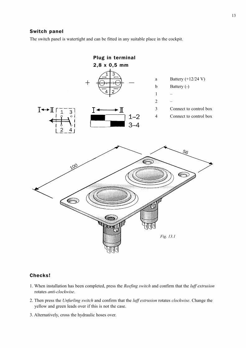
Switch panelThe switch panel is watertight and can be fitted in any suitable place in the cockpit.
Checks!
1. When installation has been completed, press the Reefing switch and confirm that the luff extrusion rotates anti-clockwise.
2. Then press the Unfurling switch and confirm that the luff extrusion rotates clockwise. Change the yellow and green leads over if this is not the case.
3. Alternatively, cross the hydraulic hoses over.
a Battery (+12/24 V)b Battery (-)1 –2 –3 Connect to control box4 Connect to control box
Plug in terminal2,8 x 0,5 mm
Fig. 13.1
14
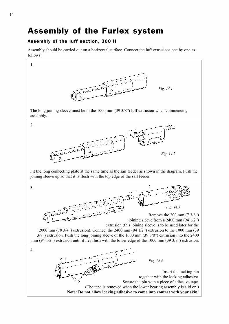
Insert the locking pintogether with the locking adhesive.
Secure the pin with a piece of adhesive tape.(The tape is removed when the lower bearing assembly is slid on.)
Note: Do not allow locking adhesive to come into contact with your skin!
Remove the 200 mm (7 3/8”)joining sleeve from a 2400 mm (94 1/2”)
extrusion (this joining sleeve is to be used later for the2000 mm (78 3/4”) extrusion). Connect the 2400 mm (94 1/2”) extrusion to the 1000 mm (39
3/8”) extrusion. Push the long joining sleeve of the 1000 mm (39 3/8”) extrusion into the 2400 mm (94 1/2”) extrusion until it lies flush with the lower edge of the 1000 mm (39 3/8”) extrusion.
Fit the long connecting plate at the same time as the sail feeder as shown in the diagram. Push thejoining sleeve up so that it is flush with the top edge of the sail feeder.
The long joining sleeve must be in the 1000 mm (39 3/8”) luff extrusion when commencing assembly.
Fig. 14.1
Fig. 14.2
Fig. 14.3
Fig. 14.4
1.
2.
3.
4.
Assembly of the Furlex systemAssembly of the luff section, 300 H
Assembly should be carried out on a horizontal surface. Connect the luff extrusions one by one as follows:

15
Fit a joining sleeve into the next 2400 mm (94 1/2”) extrusion together with a connecting plate.Connect this to the lower extrusions. Using a spare joining sleeve, push in the distance tube fromthe top until the lower joining sleeve touches the distance tube below the join. Check that the dis-tance (J) between the end of the distance tube and the end of the extrusion is approximately halfthe length of a joining sleeve.
Connect the remaining extrusions according to ”Table 2” (see page 7).
Fig. 15.1
Fig. 15.2
J5.
6.
Fit the halyard swivel over the top end of the extrusion, slide it down as far as the sail feeder andsecure it in this position with adhesive tape. Fit the top guard and secure it with the two pre-fittedscrews. Tighten the screws until they bottom, but do not over-tighten.
Fig. 15.3
7.

16
Assembly of the Furlex systemAssembly of the luff section, 400 H
Assembly should be carried out on a horizontal surface. Connect the luff extrusions one by one as follows:
Fit the long joining sleeve at the same time as the long connecting plate into a 2400 mm (94 1/2”) luff extrusion and guide the sail feeder on.
Insert a distance tube (L = 2100 mm (82 11/16”)) and push the joining sleeve until it lies flush with the lower edge of the sail feeder.
Fit the 1000 mm (39 3/8”) luff extrusion onto the connecting plate.
Push the distance tube until the long joining sleeve touches the 1000 mm (39 3/8”) luff extrusion. Use a short joining sleeve to push the distance tube down the last part of the way. Check that the distance (J) between the end of the distance tube and the end of the extrusion is approximately half the length of the joining sleeve.
Fig. 16.1
Fig. 16.2
Fig. 16.3
Fig. 16.4
1.
2.
3.
4. J

17
Fit a joining sleeve into the next 2400 mm (94 1/2”) extrusion together with a connecting plate. Connect this to the lower extrusions. Using a spare joining sleeve, push in the distance tube from the top until the lower joining sleeve touches the distance tube below the join. Check that the dis-tance (J) between the end of the distance tube and the end of the extrusion is approximately half the length of a joining sleeve.
Connect the remaining extrusions according to ”Table 2” (see page 7).
Fit the halyard swivel over the top end of the extrusion, slide it down as far as the sail feeder and secure it in this position with adhesive tape. Fit the top guard and secure it with the four pre-fit-
ted screws. Tighten the screws until they bottom, but do not over-tighten.
5.
6.
7.
Fig. 17.1
Fig. 17.2
J
Fig. 17.3 400 H

18
Forestay wire
1. Chamfer the wire end slightly with a file.
2. Thread the wire through from the top. Should the wire snag inside the extrusions twist it anticlock-wise past the obstruction.
3. Apply tape tightly to both sides of the cutting mark and cut the wire.
4. Slide the drive unit over the 1000 mm extrusion from below.
5.
6.
Dismantle the rigging screw wire terminal.
Thread the Terminal M piece with washer over the wire. twist the wedge on to the wire core. Twist the outer strands correctly over the wedge (anti-clockwise seen from below).
Circular clip
Fig. 18.2
Fig. 18.1
Bushing
Terminal F Former
Wedge
Wedge
Washer
Terminal M
Terminal M
Check again that no strands lie in the wedge slot.
7.
Push the wire with wedge down into Terminal M, ensuring that the wire strands are held evenly spread around the wedge. The wire core should protrude about 2 mm from the wedge. Tap the wedge lightly so that the outer strands become properly wedged. Bend the outer strands inwards slightly with the channel-joint pliers.
Fig. 18.3
ca 2 mm

19
9.
10.
Undo the terminal again and check that the strands are evenly spread. Any strands that may have crossed each other must be separated.
Check again that no strands lie in the wedge slot.
Put a few drops of locking adhesive on the threads and screw the terminal together. Tighten hard – this is a permanent fitting.
Note! Avoid getting locking adhesive on your skin.
Fig. 19.3
Fig. 19.2
8.
Place the former in the Terminal F piece and screw the terminal together so that the strands beco-me formed between the wedge and the former. Avoid damaging the surface of the female terminal piece with your spanner.
Fig. 19.1
Former
Terminal F

20
11.
Any sharp edges in the Terminal F piece caused by spanner damage should be filed down. Fit the bushing and circular clip. Check that the bushing rotates freely and that the circular clip is pro-perly bedded.
Fig. 20.1
Lock washer
BushingTerminal F
Key grip
12.
Assemble the rigging screw and lower toggle. Fully extend the rigging screw to facilitate rigging. Temporarily fit the locking screws.
Rigging screw
Fig. 20.2
Lower toggle
Locking screws
21
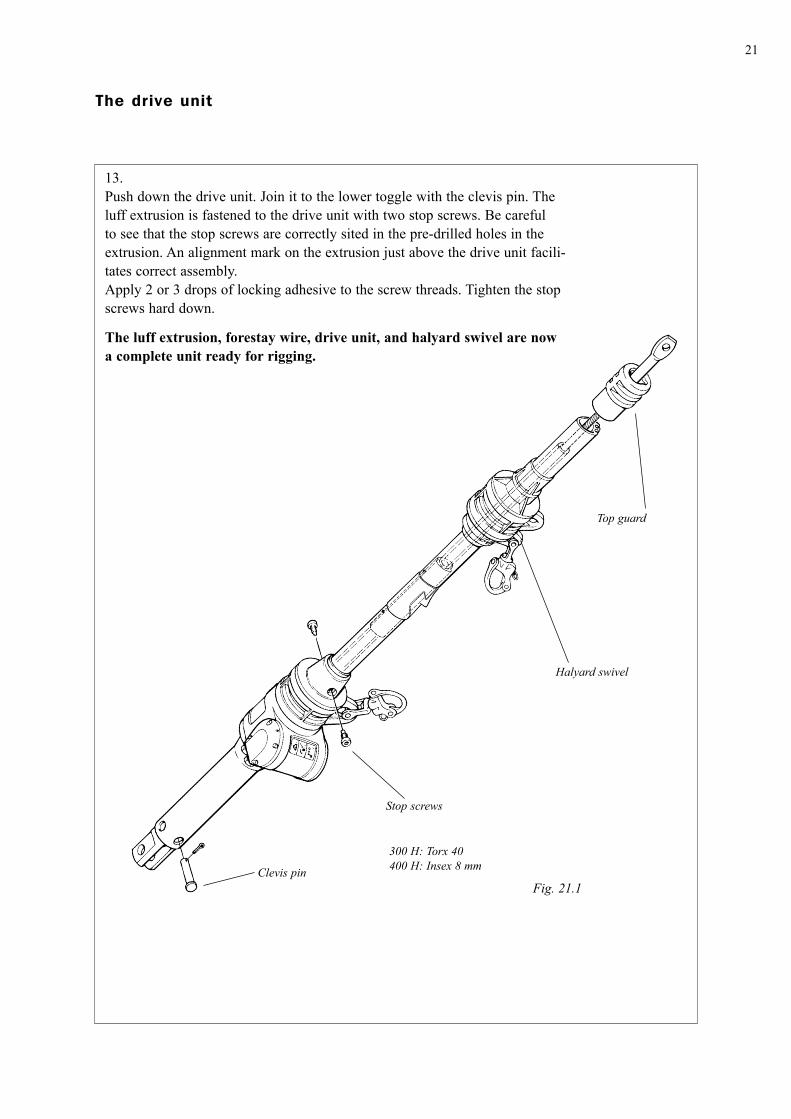
13.Push down the drive unit. Join it to the lower toggle with the clevis pin. The luff extrusion is fastened to the drive unit with two stop screws. Be careful to see that the stop screws are correctly sited in the pre-drilled holes in the extrusion. An alignment mark on the extrusion just above the drive unit facili-tates correct assembly. Apply 2 or 3 drops of locking adhesive to the screw threads. Tighten the stop screws hard down.
The luff extrusion, forestay wire, drive unit, and halyard swivel are now a complete unit ready for rigging.
The drive unit
Top guard
Halyard swivel
Stop screws
Clevis pin
300 H: Torx 40400 H: Insex 8 mm
Fig. 21.1

22
Fig. 22.1 Fig. 22.2
Fig. 22.3 Fig. 22.4
Fig. 22.5 Fig. 22.6
300
mm
Halyard leadsWhen the sail is furled on a rotating luff extrusion the halyard is also inclined totwist around the extrusion because of internal friction in the swivel. If this shouldoccur furling will stop and may cause damage.
To prevent this from happening the halyard should be angled at least 10° from the forestay (see Fig. 22.2). This requirement is seldom fulfilled, in which case the halyard must be led through the halyard lead (No 508-128) supplied. (See figs. 22.3 and 22.4). The kit contains two halyard leads. If the mast is fitted with two genoa halyards then both halyard leads should be fitted in case the No. 2 halyard should be inadvertently connected to the halyard swi-vel. The halyard leads are fitted beside each other. Fitting dimensions for Seldén Masts are given figs. 22.3 and 22.4. The same values can often be used for masts from other suppliers, but the angle must then be carefully checked. Too great an angle can cause severe halyard chafe.
If a new mast is being made for use with Furlex it is recommended to fit a halyard box just under the mast-head box. Halyard chafe from a halyard lead can the be entirely eliminated. It is possible to modify an old mast, but the extensive work involved may not be worth the advantage gained. See figs. 22.5 and 22.6.

23
Fitting the halyard leads1. Determine location of the leads2. Using the adhesive insulation pads as templates, drill the fixing
holes with the 5.2 mm drill bit supplied.3. Fit the leads over the halyards as it is not possible to thread them
through afterwards because of the shackles.4. Grease the screws and fasten the leads. The screws are self-tapping
M6 and will fit the Ø 5.3 mm holes.
RiggingIt is best to handle the Furlex stay together with the mast.
Mast down1. Lift the mast with its aft facing down.2. Allow the stay to rest on the forward face of the mast.3. One person should control the Furlex stay the whole time to make sure it does not get damaged.
Hold it over the side to avoid damages.
Mast up1. Slacken off the backstay to its maximum.2. Pull the mast-top forward with the genoa haly-
ard. Do not use the snap shackle, but use either a bolt shackle or tie it to a cleat.
3. Put a whipping of half-hitches around the top of the luff extrusion. Tape it to prevent it from slip-ping.
4. Haul the stay up with a spinnaker or genoa hal-yard.
5. Climb the mast and fit the top end of the Furlex stay. Use a proper bosun’s chair. Use the main halyard if there is no free foresail halyard. (See Seldén Masts ”Hints and Advice/Working Aloft”
6. After the stay has been fitted to the mast top, attach it to the stem-head fitting.
Fig. 23.2
Fig. 23.1
24
Fitting the sail
Note! Put on the protective sleeves and plugs.
The forestay must be properly tensioned each time the sail is hoisted. You shouldtherefore tension the backstay and any running backstays before hoisting the sail.
Adjusting forestay lengthAdjustment is 100 mm on the 300 H rigging screw, and 110 mm on 400 H.1. Take out the stop screws holding the luff extrusion. (See fig. 21.1)2. Undo the hydraulic hoses from the quick coupling.3. Take out the clevis pin. (See fig. 21.2)
4. Expose the rigging screw by pushing the drive unit up the foil extrusion. Keep it elevated with a halyard.
5. Remove the rigging screw lock screws. (See fig. 20.2)6. Adjust the rigging screw to the desired length.7. Re-assemble in reversed order. Ensure that the stop screws are properly located in the extrusion
holes.
Tensioning the forestayUse the backstay tensioner to tension the forestay to maximum 25% of its breaking load. (See Seldén Masts ”Hints and Advice”). Higher tension can be used for a limited period.A forestay that is tensioned hard gives better furling.
1. First check that the sail has been made to the specifications on page 31.2. Turn the luff extrusion so the luff grooves face aft.3. Turn the tack ring anti-clockwise until it comes to a distinct stop.4. Lash the prefeeder to the tack ring with a maximum 300 mm (12”) length of line. Thread the sail
through the prefeeder starting at the head.5. Connect the halyard swivel to the sail head and the halyard to the halyard swivel.6. Tack down the sail to the tack snap shackle.7. Hoist the sail in the starboard luff groove. This gives lower initial resistance when reefing. (The
sail has to ”bend” less if it is located in the starboard groove.) Check that the luff is feeding pro-perly into the sail feed.
8. Tension the halyard until a vertical crease appears in the luff of the sail, then slacken off until the crease disappears. Belay the halyard.
9. Take off the prefeeder.10. Test furl the sail a few times in harbour to check all functions.
The sail can also be handled from the port side on condition that it is made and set for that purpose.
Roll the sail on to the starboard side of the luff foil.

25
Operation
Unfurling the sailHaul in on the sheet while pressing the unfurling switch. By doing this, the sail will not flap and be subjected to excessive wear.Stop the reefing gear when the sail is fully open and the luff extrusion has a suitable angle to the apparent wind.If you continue to press the unfurling switch, the sail will start to furl again, but in the wrong direc-tion..
Furling the sailFurl the sail on the starboard side of the luff extrusion.Press the reefing switch (See fig. 13.1) while at the same time giving after on the sheet. The amount of counter-pressure you apply to the sheet will decide how tightly the sail is rolled.Continue to roll some of the sheet over the sail when the sail is fully furled.
ReefingFurlex Hydraulic is equipped with a tack-ring which is free to rotate about one revolution in relation to the luff extrusion. This helps to flatten the sail when reefed, as the tack does not start to roll in until the centre of the sail has been rolled in by that amount.god förutsätt-ning för ett plant revat segel.
Remember!Always roll in at least 2–3 revolutions.Pay out the sheet from the winch drum while applyingsome resistance.Experiment in order to find out the best method for justyour sail.Do not subject a light wind sail (light sailcloth) to heavywinds.
Sail shape when reefed can be improvedVarious methods of improving reefed sail shape have been developed. Most sailmakers apply a cloth covered plastic foam (”Luff foam”) along the luff. This material is tailo-red for the draft depth of the sail, and counter-acts draft increases as the sail is rolled in. One can also sew a ”sleeve” along the luff. In this one can place lines of different dimensions for draft compensation. The advantage of this method is that it can be varied to suit the sail with the passage of time. It is the-refore a suitable method to use if an old sail is being altered to suit your Furlex. Ask your sailmaker what method is the most suited to your requirements.

26
Manual operationA standard winch handle can be used in the event of loss of oil pressure or current.The by-pass valve is located on the through-deck fitting (see fig. 11.1).
Warning sign
Switch the by-pass valve over to ”Winch handle”
Thereafter, put the winch handle in the socket.
The hydraulic motor cannot be started when the by-pass valve is in the position for manual operation Manual operation can be undertaken in complete safety. The sail reefs when you turn the handle clockwise.
Warning! Never leave the winch handle in the drive unit. It will rotate very rapidly if the hydraulic motor is started.

27
MaintenancePeriodic examination and maintenance of the system is necessary if it is to operate easily and give long service. Give it a thorough examination on a regular basis. Follow the schedule below.
CleaningWash and rinse the entire Furlex system with fresh water to remove dirt and salt. This is especially important with the lower parts of the unit, and in particular the tack swivel, as these are most exposed to salt water.This is the most important service item.It is alright to use detergents provided that all traces are rinsed off afterwards. Most detergents con-tain elements that can corrode aluminium alloys.Treat all anodized aluminium surfaces afterwards with a silicone-free boat polish or wax. This provi-des good protection and reduces soiling of the sail.
GreasingAvoid using too much grease. The halyard swivel bearings should be greased with the tube of grease supplied with the Furlex (part no. 312-501).The two halyard swivel bearings are lubricated by injecting grease into the ball race gaps.The tack ring top bearing is lubricated by injecting the grease through the gap into the ball race.The tack ring bottom bearing is lubricated via a hole in the centre of the tack ring.
Periodic servicingThe drive unit gearing is greased with a lithium-based grease (SKF LGEP 2/04). We recommend that you have the unit serviced at intervals of no more than 5 years in normal use. Servicing entails disas-sembly and cleaning of the unit, replacement of the glands and O-rings and re-greasing.
For boats used in charter operations or circumnavigation etc the unit should be serviced on a more frequent basis.
StorageRinse the Furlex system to remove all salt and dirt. Store it in a dry, well ventilated place. The drive unit can be detached easily for storage separately. The Furlex stay is best stored together with the mast.
Under no circumstances should an unwashed or damp Furlex be wrapped in plasticor other impervious material.

28
Dismantling
The drive unit
With forestay off the mastThe entire drive unit is dismantled by pushing it upwards over the luff extrusion, see fig 21.1. The sail feeder, halyard swivel, and top guard must first be removed from the extrusion.
With forestay rigged
1. Dismantle the terminal fitting (see pages 18 and 24).2. The drive unit is then removed from the forestay by pushing it downwards.3. Further dismantling of the Hydraulic drive unit should be left to Seldén Mast AB.
(Exception; see under Hydraulic motor unit, page 30.)
Note! This is a simple operation with forestay wires of Ø 8, 10 and 12 mm. However,with Ø 14 mm wire the male terminal piece has a larger diameter than the luff foil.The alternative is either to unrig the forestay, or to saw off the wire just above themale terminal piece. (The stay will then be shortened by 80 mm.)
Forestay wire
The wire terminal must first be removed before the wire can be pulled out of the luff extrusion. As this has been tightened down for permanent fitting (fig. 19.3) it is important that the following iscarefully followed for a successful operation.
1. Unrig the reefing system, see page 23, and lay it out on a clean and smooth surface. Dismantling then mainly follows a reversal of the order of assembly described on pages 14–21. The following describes only what especially applies to dismantling.
2. Dismantle the rigging screw, circular clip, and bushing from the Terminal F piece.3. Unscrew male and Terminal F pieces. The threads are locked with locking adhesive. Heat the
Terminal F piece to approx 100°C (212° Fahrenheit) and unscrew the parts while they are still hot.4. Remove the former lying in the bottom of the Terminal F part and remove the washer from the
Terminal M piece.5. Screw male and Terminal F parts together, and then loosen one or two turns.

29
7. Saw off the outer strands where they are bent inwards, so that the wedge can be removed.8. Pry the wedge open slightly by putting a screwdriver into the slot and twisting. Pull the wedge off.
Correct the twist of the strands. (Anti-clockwise seen from below.)9. Pull the wire out through the top of the extrusion.
Luff extrusion systemFor a better understanding of the following instructions, we recommend that you first read the section on assembly on pages 14–21.1. Make sure that the luff extrusions are straight and pla-
ced on a flat surface.2. Push the wire into the luff extrusion system until the
end of the wire is approx. 50 mm (2”) inside the 1000 mm (39 3/8”) extrusion.
3a. 300 H: Knock out the locking pin at the lower end of the 1000 mm (39 3/8”) luff extrusion.
3.b 400 H: Knock out the bushes at the lower end of the 1000 mm (39 3/8”) luff extrusion. See Fig. 29.2.
4. Slide the wedge over the core of the wire again.5. Hold the luff extrusion system firmly and pull the wires eye terminal. This will bring the forestay,
bearing plug (400 H) in the 1000 mm (39 3/8”) luff extrusion, joining sleeves and distance tubes out together, enabling the luff extrusions to be separated.
If, due to contamination or damage this method fails the connecting plates can be drilled out. Use a Ø 8 mm drill bit.
Reassemble of the luff extrusion.1. Check all metal corners, edges and holes for damage, and file down if necessary.2. Clean the wire and all extrusion parts with fresh water.3. Refit the bearing plug into the 1000 mm luff extrusion.Then follow pages 14–21. The inner strands of the wire must be cut level with the outer strands before starting re-assembly.
400 HFig. 29.2
6. Hold the wire between two aluminium pads in a heavy vice (see fig. 29.1). Protect the threaded stud with a mandrel, and give it a sharp hit with a heavy (appr. 1,5 kg/3 1/2 lbs) hammer. (See arrow.) The wire should then free itself from its conical seat in the male terminal piece. Remove the wire from the vice, and unscrew the male and female terminal pieces.
Jaw pads (Aluminium)
Tube mandrel
Max 10 mm
Fig. 29.1
Heavy vice
Terminal F
Terminal M

30
Halyard swivelDo not dismantle the halyard swivel. It can be very difficult to re-assemble correctly. (The balls in the ball races become loose among other things.)
The Hydraulic Motor
The hydraulic motor should only be removed from the drive unit if it is not possible to turn the winch handle (see Manual Operation, page 26), or if the motor has to be replaced. The most likely reason for this would be that there are impurities in the oil.
Remove the hydraulic hoses. Apply the protective plugs.Remove the four Allen screws holding the cover on the port side (5 mm Allen key). Pull out the cover evenly by using the three dismantling screws (2.5 mm Allen key). Then carefully remove the motor by hand. Do not use any other tools.Cover the open hole where the motor was seated tightly and accurately.The drive unit can easily be operated manually even when the hydraulic motor has been removed.
Important! See ”Installation” page 11.
Important! The cover and the motor form an integral unit that must not be dismant-led.
If service or repair is necessary, contact your Furlex dealer.
Stop screws, 2 off
Allen screws, 4 off
Dismantling screws3 off
Luff extrusion
Drive unit
Fig. 30.1Hydraulic Motor

31
The sail
The sail should be made for rolling up on the starboard side of the luff foil.Any sun-strip should therefore be on the starboard side of the sail.A high cut clew can give a constant sheet angle even when reefing.The luff tape ”hard line” should end above the sail feed. (See fig. 31.1).We recommend webbing on both the head and tack.
Wire head pendantSail with a luff more than 500 mm (19”) shorter than the maximum luff length should be fitted with a per-manent wire head pendant. The pendant and sail luff together should not have a total length exceeding the maximum permissible luff length.
Fig. 31.1
Fig. 31.2
Fig. 31.3
Max luff length = FL (F+E)
FL
1100 mm
E
F
FurlexHydraulic
Type
Extrusion Dimension
Amm
Bmm
MaxLuff tape
mm
Cut-backCB mm
Fmm
Emm
F+EMM
300 H 39/27 3.0 Ø 7.5 Ø 6.5 80 550 490 1040400 H 48/34 3.0 Ø 8 Ø 6.5 100 650 675 1345

Important points to remember before sailing
595-
119-
E
P
rint
ed in
Sw
eden
.
Sel
dén
and
Furl
ex a
re r
egis
tere
d tr
adem
arks
of
Seld
én M
ast A
B
� The sail rolls on to the starboard side of the luff extrusion.
� The halyard angles out 5–10° from the forestay with sail set.
� All sails used have the right total luff length. See page 31.
� No lines or halyards can get caught in either the swivel or sail.
� The tack ring is in the right position. See page 20.
� The winch handle is not in the drive unit when that is out of use. It will rotate very fast if the sail is rolled in or out.
� The by-pass valve is correctly set when operating manually.
� The quick couplings are properly locked. See page 11.
Seldén Mast AB, Sweden Tel +46 (0)31 69 69 00 Fax +46 (0)31 29 71 37 e-mail [email protected]
Seldén Mast Limited, UK Tel +44 (0) 1329 504000 Fax +44 (0) 1329 504049 e-mail [email protected]
Seldén Mast Inc., USA Tel +1 843-760-6278 Fax +1 843-760-1220 e-mail [email protected]
Seldén Mast A/S, DK Tel +45 39 18 44 00 Fax +45 39 27 17 00 e-mail [email protected]
Seldén Mid Europe B.V., NLTel +31 (0) 111-698 120 Fax +31 (0) 111-698 130 e-mail [email protected]
Seldén Mast SAS, FRTel +33 (0) 251 362 110 Fax +33 (0) 251 362 185 e-mail [email protected]
www.seldenmast.com
Dealer:
DINGHIESKEELBOATSYACHTS
The Seldén Group is the world’s leading manu-
facturer of masts and rigging systems in carbon
and aluminium for dinghies, keelboats and yachts.
The Group consists of Seldén Mast AB in Sweden,
Seldén Mast A/S in Denmark, Seldén Mast Ltd in
the UK, Seldén Mid Europe B.V. in the Netherlands,
Seldén Mast Inc in the USA and Seldén Mast SAS
in France. Our well known brands are Seldén and
Furlex. The worldwide success of Furlex has ena-
bled us to build a network of over 750 authorised
dealers covering the world’s marine markets. So
wherever you sail, you can be sure of fast access to
our service, spare parts and know-how.