Embed Size (px)
Citation preview

7/25/2019 Manual for APFC
http://slidepdf.com/reader/full/manual-for-apfc 1/15
Automatic Power Factor Correction Panels
Installation and Maintenance instructions for APFC Panels
Series/Type :
Ordering Code : B2517
Date : Feb 2009
Version : 1.1
EPCOS AG 2008, Reproduction, Publication and dissemination of this data sheet, enclosures hereto and the
information contained therein without EPCOS prior consent is prohibited
PDF created with FinePrint pdfFactory Pro trial version www.pdffactory.com
7/25/2019 Manual for APFC
http://slidepdf.com/reader/full/manual-for-apfc 2/15
Installation and maintenance instructions for APFC panels
Preliminary data
Installation and Maintenance Instructions
Read This First : Read the following >> Installation and maintenance instructions << carefully
before installing a APFC Panel into your application.
About this manual The information stated in this manual applies to typical, approved usage. Pleaserefer to our product specifications, or request our approval for your own
individual specifications, before installing APFC panels
For your safety! Disregarding the guidelines in this manual can result in operational failure
bursting and fire. In case of doubt, contact your local EPCOS sales organization
or distributor for assistance.
General safety notes for Ensure you are using the right APFC panel for your application, please refer to
installation and operation the EPCOS product catalogue and application notes for proper selection ofAPFC Panel and its configuration.
Maintain good and effective grounding for APFC panel
Provide the means to isolate any faulty units/ banks in the system
Follow proper engineering practices
Storage and operation Donot use or keep APFC panel in corrosive atmosphere, especially where
Conditions as, sulphide gas, acid, alkali, salt or similar substances are present. In a dustyenvironment, regular maintenance and cleaning, especially of the contacts, is
required to avoid a conductive path between phases and /or phases and ground.
• The panel has to be stored with outer packing intact in a covered area under
protection from rain. The panel should stand in vertical position as indicated
in the packing crate.
Ambient temperature : The ambient temperature category for most standard types is -40D. This means
a max. temperature of 55DegC, an average temperature over 24 hours of
45DegC, and the average temperature in one year should not exceed 35 Deg C.
PDF created with FinePrint pdfFactory Pro trial version www.pdffactory.com

7/25/2019 Manual for APFC
http://slidepdf.com/reader/full/manual-for-apfc 3/15
Installation and maintenance instructions for APFC panels
Preliminary data
Caution :
PDF created with FinePrint pdfFactory Pro trial version www.pdffactory.com

7/25/2019 Manual for APFC
http://slidepdf.com/reader/full/manual-for-apfc 4/15
Installation and maintenance instructions for APFC panels
Preliminary data
Installation :
Mounting the APFC Panel : The place has to be identified where the panel has to be
erected. It should be level and hard. The incoming cables
should be brought depending upon the cable entry provisions of the panel. The cross section of the cableshould be commensurate with the maximum kVAr rating of
the panel.The panel has to be shifted to the installation place. The
incoming cables has to be connected to the incomer afterfixing the appropriate cable lugs.
Earthing has to be provided at the designated place in the panel.
The panel has to be handled and unloaded carefully withoutdamage.
Proper fork lift and rollers have to be employed. It should be never toppled as it is delicate.
Mounting Positions : APFC Panel should be always Verticle
Warning : Do not install the Panel in-case of
PDF created with FinePrint pdfFactory Pro trial version www.pdffactory.com

7/25/2019 Manual for APFC
http://slidepdf.com/reader/full/manual-for-apfc 5/15
Installation and maintenance instructions for APFC panels
Preliminary data
Incomer Cable sizing : The incomer cable sizing should be commensurate with the kVAr
rating of the panel. Allowances should be considered for increase
in current due to presence of harmonics, overvoltage and kVAr
tolerance. Following table gives the cable sizes to be used for
different kVAr ratings.
Capacitor health checking : It is recommended to check the health of the capacitor in
the APFC panel prior to commission the panel. It is alsoadvisable to periodically check the capacitor health once in
six months to detect any de-rating. The best way to check
the capacitor condition is to measure the capacitance valueafter switching of the panel and completely discharging the
capacitor. The capacitor value should be within the
tolerance value.
The recommended values of capacitance for different kVAr
@ different voltages are given in the following table.
PDF created with FinePrint pdfFactory Pro trial version www.pdffactory.com

7/25/2019 Manual for APFC
http://slidepdf.com/reader/full/manual-for-apfc 6/15
Installation and maintenance instructions for APFC panels
Preliminary data
Pre-charging checks : Check the tightness of internal connections. This should include
capacitor connection, bus bar joints and other connections.Ensure that recommended ratings of fuses are put in the incomer
and there are no loose connections.Ensure the secondary of sensing CT are connected to the panel at t
the designated terminal. The sensing CT has to be mounted suchthat both load and APFC panel current flows through it. It should
be connected upstream of the APFC panel and load.The APFC controller is pre-programmed in EPCOS factory. It
should not be altered. If it has to be changed, it should be done
only by authorized persons under instruction from EPCOS. Therelevant controller manual should be referred for setting the parameters in the APFC controller. Wrong settings can adversely
affect the panel performance and eventual failure of panelcomponents.
PDF created with FinePrint pdfFactory Pro trial version www.pdffactory.com

7/25/2019 Manual for APFC
http://slidepdf.com/reader/full/manual-for-apfc 7/15
Installation and maintenance instructions for APFC panels
Preliminary data
Commissioning procedure : Ensure that some minimum load say 10% of the connectedload is on before switching on the APFC panel.
The APFC controller will display the power factor of theload prior to compensation. It should be inductive
(Lagging). If it is showing as capacitive, then the controlCT terminal has to be reversed.
The reversing of CT terminal has to be done carefully suchthat, the CT terminal is never open circuited. The shorting
link has to be closed at the CT terminal point. The CTconnection going to PF controller should now be reversed.
Then the shorting link should be reversed. Now the PFindicated by the PF controller should read inductive.
After 90 seconds of switching on the APFC panel, the stepsin the APFC panel should switch on one by one depending
upon the quantum of load and its reactive power demand. Ifthis does not happen , then check that the APFC controller
is set to ‘Auto’ mode and if not set it to ‘Auto’ mode.
PDF created with FinePrint pdfFactory Pro trial version www.pdffactory.com

7/25/2019 Manual for APFC
http://slidepdf.com/reader/full/manual-for-apfc 8/15
Important Notes :
The following applies to all products named in this publication:
1. Some parts of this publication contain statements about the suitability of our products for
certain areas of application. These statements are based on our knowledge of typicalrequirements that are often placed on our products in the areas of application concerned. Wenevertheless expressly point out that such statements cannot be regarded as bindingstatements about the suitability of our products for a particular customer application. As arule, EPCOS is either unfamiliar with individual customer applications or less familiar with themthan the customers themselves. For these reasons, it is always ultimately incumbent on thecustomer to check and decide whether an EPCOS product with the properties described in theproduct specification is suitable for use in a particular customer application.
2. We also point out that in individual cases, a malfunction of electronic components orfailure before the end of their usual service life cannot be completely ruled out in thecurrent state of the art, even if they are operated as specified. In customer applicationsrequiring a very high level of operational safety and especially in customer applications in which
the malfunction or failure of an electronic component could endanger human life or health (e.g. inaccident prevention or life-saving systems), it must therefore be ensured by means of suitabledesign of the customer application or other action taken by the customer (e.g. installation ofprotective circuitry or redundancy) that no injury or damage is sustained by third parties in theevent of malfunction or failure of an electronic component.
3. The warnings, cautions and product-specific notes must be observed.
4. In order to satisfy certain technical requirements, some of the products described in thispublication may contain substances subject to restrictions in certain jurisdictions (e.g.because they are classed as hazardous). Useful information on this will be found in ourMaterial Data Sheets on the Internet (www.epcos.com/material). Should you have any moredetailed questions, please contact our sales offices.
5. We constantly strive to improve our products. Consequently, the products described in thispublication may change from time to time. The same is true of the corresponding productspecifications. Please check therefore to what extent product descriptions and specificationscontained in this publication are still applicable before or when you place an order.
We also reserve the right to discontinue production and delivery of products. Consequently,we cannot guarantee that all products named in this publication will always be available. Theaforementioned does not apply in the case of individual agreements deviating from the foregoingfor customer-specific products.
6. Unless otherwise agreed in individual contracts, all orders are subject to the current versionof the “General Terms of Delivery for Products and Services in the Electrical Industry”published by the German Electrical and Electronics Industry Association (ZVEI).
7. The trade names EPCOS, BAOKE, Alu-X, CeraDiode, CSSP, CTVS, DSSP, MiniBlue, MKK,MLSC, MotorCap, PCC, PhaseCap, PhaseMod, SIFERRIT, SIFI, SIKOREL, SilverCap, SIMDAD,SIMID, SineFormer, SIOV, SIP5D, SIP5K, ThermoFuse, WindCap are trademarks registered orpending in Europe and in other countries. Further information will be found on the Internet at
www.epcos.com/trademarks.
PDF created with FinePrint pdfFactory Pro trial version www.pdffactory.com

7/25/2019 Manual for APFC
http://slidepdf.com/reader/full/manual-for-apfc 9/15
PDF created with FinePrint pdfFactory Pro trial version www.pdffactory.com

7/25/2019 Manual for APFC
http://slidepdf.com/reader/full/manual-for-apfc 10/15
Introduction
All electrical equipment needs reactive power apart from active power for their operation.
The need for reactive power arises because the current and voltage waveform are not in phase with each other. In Inductive loads, the current lags the voltage and in capacitive
loads the current leads the voltage. The power factor is defined as the cosine of the angle between current and voltage vector. When the current and voltage vector are perfectly in
phase as in the case of a purely resistive load, the phase angle between voltage andcurrent is zero and the power factor is unity. This power factor is called the displacement
power factor as it relates to displacement of current vector with respect to voltage vector.The displacement power factor is lagging in case of inductive load and leading in case of
capacitive load.
If inductors and capacitors are connected in parallel, then the inductive current which is90 degrees lagging with respect to applied voltage is exactly opposite in direction to
capacitive current which is 90 degrees leading to applied voltage. Thus the capacitive
current can neutralise the inductive current and vice versa thereby reducing the reactivecurrent considerably in the circuit. This is the essence of reactive power compensation.
Since the predominant loads are inductive in nature capacitors are used for reactive power compensation. If the loads are steady, then we can consider fixed compensation by
using fixed capacitors. But usually the loads are fluctuating requiring varying reactive power requirement and to compensate such a load the capacitors need to be switched.
The following types of switching devices are available for switching the capacitors.
1. Ordinary Contactors
They are most cost effective solutions available. They can be used when the variation inreactive power with respect to time is slow and capacitor switching interval greater than
60 seconds. More rapid switching rate is not possible with contactors as it will damagethe contacts. More over minimum time of 60 seconds is to be allowed before
reconnecting a disconnected capacitor to allow the capacitor to completely discharge before reconnection to avoid premature capacitor failure. This makes contactor switched
systems suitable for only slow varying loads.
Another serious issue with use of ordinary contactors is the inrush current associatedwhile switching capacitors. Capacitors tend to draw very large transient currents of 75 to
150 times their steady state currents at the time of switching. This is because the rate of
change of voltage (dv/dt) across the capacitor terminals is very large at the time ofswitching. The current through the capacitor being proportional to dv/dt is also verylarge. The duration of this large current although is very small, typically less than 1 msec,
can cause capacitors to fail and contacts of the contactor to weld. The inrush current isoscillating in nature and can cause failure of sensitive loads in the network. Thus a
serious power quality issue arises by the use ordinary contactors in switching capacitors.
PDF created with FinePrint pdfFactory Pro trial version www.pdffactory.com

7/25/2019 Manual for APFC
http://slidepdf.com/reader/full/manual-for-apfc 11/15
To overcome these difficulties inrush limiting air core coils are used in series withcapacitors. These coils are used only on two of the three phases of the capacitor. The
coils are made out of the connecting wires to the capacitor with 8 to 10 turns anddiameter of approximately 10 cms. Alternatively a capacitor duty contactor can be used
to limit the inrush current as mentioned below.
2. Capacitor duty contactors
Capacitor duty contactors have additional auxiliary contacts with current
limiting resistors (also called pre charging resistors) in series with it. Theinrush current is limited by these auxiliary contacts coming on first and then
the main contacts takes over the steady state current of the capacitors.
3. Thyristor modulesThyristor modules are very effective in eliminating the inrush current of capacitors. They
are controlled switching devices which can be made to switch on when the voltage acrossthe Thyristor is zero, thereby eliminating the inrush current. Additionally, Thyristor are
used when the load variation is rapid like cranes, lifts, spot welding, plastic extrusion etc.
Harmonic environment
Harmonic environment is said to exist when non-linear loads are extensively used in a
network. Non-linear loads are power electronic loads which draws non sinusoidal currentwaveform when fed from sinusoidal voltage waveforms. Examples of such loads are
AC/DC drives, UPS, converter/inverter, computers, CFL Lamps etc.
In the presence of harmonic environment, power factor correction should not be
done by conventional power capacitors as it will cause unhealthy harmonic
amplification due to parallel resonance between power factor correction capacitors and
transformer/system impedance.
In such an environment the power factor correction capacitors have to be replaced byHarmonic filters (Tuned or De-tuned).
PDF created with FinePrint pdfFactory Pro trial version www.pdffactory.com

7/25/2019 Manual for APFC
http://slidepdf.com/reader/full/manual-for-apfc 12/15
Classification of APFC panels
APFC panels can thus be classified as follows.
APFC Panel
Capacitor Based De-Tuned filter
based
Tuned filter based
ContactorBased
ContactorBased
ContactorBased
ThyristorBased
ThyristorBased
ThyristorBased
PDF created with FinePrint pdfFactory Pro trial version www.pdffactory.com

7/25/2019 Manual for APFC
http://slidepdf.com/reader/full/manual-for-apfc 13/15
Panel sizing calculation (kVAr.)
Estimating the panel rating in kVAr has to be done knowing the present uncompensated
power factor (initial PF) and the desired PF after compensation (final PF) and the peakkW loading of the load. Following table gives the multiplying factor to be used inestimating the panel kVAr.
Panel kVAr rating = multiplying factor X kW of the load
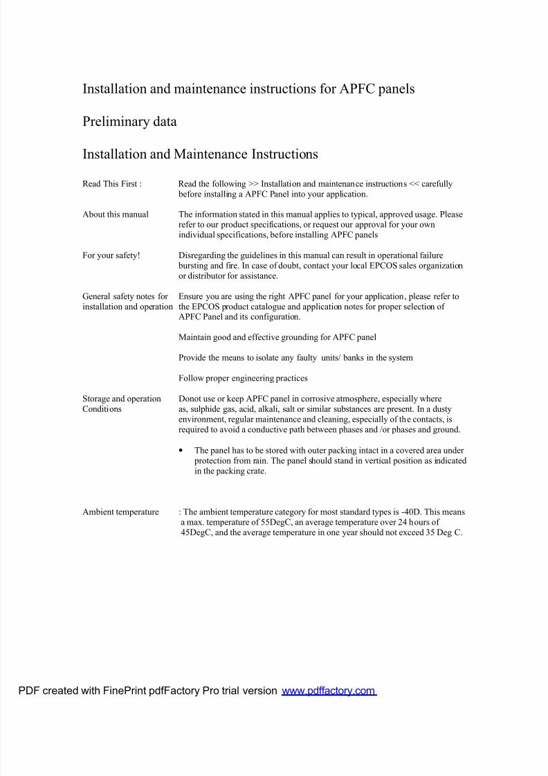
Location of sensing CT
The location of sensing CT which senses the corrected power factor is very important for
proper functioning of the APFC panel. The following diagram shows the correct position
of the sensing CT. Also indicated are commonly used wrong positions of CT, whichshould not be used. The APFC panel will not work properly in these cases.
PDF created with FinePrint pdfFactory Pro trial version www.pdffactory.com

7/25/2019 Manual for APFC
http://slidepdf.com/reader/full/manual-for-apfc 14/15
PDF created with FinePrint pdfFactory Pro trial version www.pdffactory.com

7/25/2019 Manual for APFC
http://slidepdf.com/reader/full/manual-for-apfc 15/15