Embed Size (px)
Citation preview

Using XY-pic in LYX
H. Peter Gumm
January 25, 2013
With the recent versions of LYX and with the preview-style installed inthe LATEX-System, the graph drawing package XY-pic can be convenientlyused inside LYX. Diagrams can be edited and displayed inside the mainLYX editing window. Here, we shall describe how to use the \xymatrix
command from xypic inside LYX in order to draw, to edit and to previewdiagrams as typically used in category theory, algebra, and related fields.
Contents
1 Introduction 2
2 Preparation 3
3 Commutative diagrams 43.1 The matrix layout of diagrams . . . . . . . . . . . . . . . . 43.2 Arrows . . . . . . . . . . . . . . . . . . . . . . . . . . . . . 43.3 Labels . . . . . . . . . . . . . . . . . . . . . . . . . . . . . 53.4 Arrow modification . . . . . . . . . . . . . . . . . . . . . . 6
3.4.1 Arrow design . . . . . . . . . . . . . . . . . . . . . 63.4.2 Designing your own arrows . . . . . . . . . . . . . . 7
3.5 Arrow positioning . . . . . . . . . . . . . . . . . . . . . . . 73.5.1 Inline or centered diagrams . . . . . . . . . . . . . 7
3.6 Bending arrows . . . . . . . . . . . . . . . . . . . . . . . . 83.6.1 Raising the shaft . . . . . . . . . . . . . . . . . . . 83.6.2 Specifying exit- and entrance directions . . . . . . . 8
3.7 Modifying vertices . . . . . . . . . . . . . . . . . . . . . . 93.7.1 Framing objects . . . . . . . . . . . . . . . . . . . . 93.7.2 Framing rectangles . . . . . . . . . . . . . . . . . . 9
1

4 Using LYX’s math editor 104.1 Caveat - how to enter braces . . . . . . . . . . . . . . . . . 104.2 Setting up the matrix . . . . . . . . . . . . . . . . . . . . . 104.3 Entering nodes, arrows and labels . . . . . . . . . . . . . . 104.4 Modifying arrows . . . . . . . . . . . . . . . . . . . . . . . 114.5 What if something goes wrong . . . . . . . . . . . . . . . . 11
5 Hacks 115.1 Horizontal and vertical scaling . . . . . . . . . . . . . . . . 115.2 Label positioning . . . . . . . . . . . . . . . . . . . . . . . 125.3 Invisible stretched arrows . . . . . . . . . . . . . . . . . . . 125.4 Further XY-tricks . . . . . . . . . . . . . . . . . . . . . . . . 13
1 Introduction
The xypic-package has long served as a convenient tool for easily constructing graphsand diagrams in LATEX. Unfortunately, its use in LYX had long been restricted to theinfamous TEX code boxes, meaning that the LYX editor could only display the LATEX-source and not the finished diagram. The new preview-style of LATEX which is part ofthe AUCTEX project[4], finally enables the editing and displaying of xypic-diagrams,constructed, displayed and interactively edited inside LYX.
In this note, we describe how XY-pic can be used from inside LYX, how diagramscan be created and edited. We have tested the following using LYX versions 1.3.7 upto 1.6, running under Windows XP and under Windows Vista.
2

There are two modes of operations: For a start, and for some first tests, it may beeasiest to first enter the XY-pic code inside the LYX-window, select it all and convertit to a graphical representation by pressing Ctrl-m or Ctrl-M. If you use XY-pic morefrequently, or if you want to modify your initial figure, you will want to assemble andmodify your figures using LYX’s math editor.
Once the cursor is moved over a diagram, this is displayed as an array of nodesand arrow-commands. These can be changed interactively. When the cursor leavesthe editing area, the diagram reappears.
In the first two sections of this documentation, we explain how to use LYX in thefirst mentioned mode and we introduce all XY-pic features that might be of use fordrawing commutative diagrams, graphs or automata. Section 4 explains how to usethe XY-pic commands inside a math-editing area.
It is not our intention to write another introduction to XY-pic, rather our motivationis to give an introduction how the most important commands work inside LYX, sincethe keystrokes as explained in the XY-pic manual[1] will not always function correctlyinside LYX.
2 Preparation
The following requires that the LATEX-packages xypic and preview are installed inthe LATEX system. They are available from CTAN, see at [2], resp. at [3]. Afterfreshly installing them, it may be necessary, to run Tools .Reconfigure from the mainLYX menu. The steps to a first diagram output in LYX are then:
1. Activate and test preview
a) Open LYX, choose Tools .Preferences . Look and Feel .Display and turn In-stant Preview on.
b) In Document .Settings .Math Options, uncheck Use AMS Math packageautomatically and check Use AMS Math package.
c) Test, if instant-preview works by opening a LYX-document and enteringany math-formula, e. g. a+ b = c.
d) Move the cursor out of the formula, and watch it change its appearanceto look just like in the finished DVI- or PostScript document.
2. Activate and test XY-pic:
a) Inside your LYX-Document, enter the text\xymatrix{A \ar[r] & B} .
b) Select the whole text and choose Insert .Math .Display Formula, or use thecorresponding keyboard shortcut Ctrl-M.
c) Move the mouse cursor out of the editing box and wait for a split secondto see an arrow appear: A // B .
3

3 Commutative diagrams
The following diagram, which is taken from the documentation of XY-pic[1] by itscreator Kristoffer H. Rose, will provide an example for many of the features availablewith that package. Its source code is:
\xymatrix{
U \ar@/_{1pc}/[ddr]_\psi\ar@/^{1pc}/[drr]^\varphi
\ar@{.>}[dr]|-{(x,y)}\\
& X \times_Z Y \ar[d]^q \ar[r]_p & X \ar[d]_f\\
& Y \ar[r]^g & Z }
Again, to turn this code into a graphical output, select it all at once starting fromthe \xymatrix{ . . . up to the closing brace . . . } and turn it into display-math asexplained above. A moment after the cursor leaves the math-area, you should see thediagram in its full graphical glory as shown below.
U
ψ
%%
ϕ
""(x,y)
$$X ×Z Y
q
��
p// X
f
��Y
g // Z
3.1 The matrix layout of diagrams
xymatrix uses a matrix to define the layout of the vertices of a diagram. For theabove example, we need a 3× 3-matrix of which 5 entries are used for the vertices U ,X ×Z Y , X, Y , Z, the other positions remaining empty. In this case, the followingmatrix determines the layout:
\xymatrix{
U \\
& X\times_Z Y & X \\
& Y & Z }
The pattern should be familiar from LATEX: We see three rows, the first two beingterminated by the end-of-line-marker \\ . Each line consists of entries, separated bythe ampersand &.
3.2 Arrows
Having entered the vertices, we add arrows between them. The basic xypic-commandto produce an arrow is \ar , it is entered into the cell of the matrix where the arrow isto start. The target of the arrow is defined by direction commands u (up) d (down) l
4

(left), or r (right). These can be combined to a path and enclosed in square brackets.As an example, the arrows from the vertex U in the upper left corner down and rightto the vertices X ×Z Y , Y , and X are, respectively, defined as \ar[dr], \ar[ddr]and \ar[drr]. Thus the above diagram with all arrows added becomes:
\xymatrix{
U \ar[ddr] \ar[drr] \ar[dr]\\
& X \times_Z Y \ar[d] \ar[r]& X \ar[d]\\
& Y \ar[r] & Z }
U
��6666666666666666
))TTTTTTTTTTTTTTTTTTTTT
$$HHHHHHHHH
X ×Z Y
��
// X
��Y // Z
3.3 Labels
Labels are attached to arrows by affixing them as upper or lower indices to the \ar-command. Thus, \ar[drr]^\varphi defines an arrow going one cell down, two tothe right and having the label ϕ attached above. To attach a label below the arrow,make it a lower index as in \ar[ddr]_\psi. This explanation is correct only forarrows pointing to the right. More precisely, imagine looking along the arrow in thedirection it is pointing. Then an upper index places a label to the left and a lowerindex places it to the right. Consequently, an arrow pointing from right to left, suchas \ar[l]^\alpha_\beta will have label α below and label β above the arrow, e. g.
.β
αoo Using the character | instead of ˆ or , it is even possible to place the label
right onto the arrow, obscuring part of its shaft.
Normally, a label is placed halfway between an arrow’s start and target objects. Inthe first diagram, the central arrow starting in U has the label (x, y) in the middleof the arrow’s shaft, rather than in the middle between the two objects it connects.This is achieved by prefixing the label with a minus sign, here: \ar[dr]|-{(x,y)}.
\xymatrix{
U \ar[ddr]_\psi \ar[drr]^\varphi\ar[dr]|-{(x,y)}\\
& X \times_Z Y \ar[d]^q \ar[r]_p& X \ar[d]_f\\
& Y \ar[r]^g & Z }
5

U
ψ
��6666666666666666ϕ
))TTTTTTTTTTTTTTTTTTTTT
(x,y)HHHH
$$HHHH
X ×Z Yq
��
p// X
f
��Y
g // Z
XY-pic normally permits labels to be shifted towards the tip or towards the start ofan arrow by prefixing the label with a ratio, such as e. g. (.3). In LYX this worksonly for labels which are placed on top of the arrow, such as \ar[r]|(0.3){\phi}.
For labels placed to the left or to the right of the arrow this does not work. Thecorresponding XY-pic code such as e. g. \ar[r]^(.3)\phi or \ar[r]_(.3)\psi is notcorrectly interpreted by LYX’s math editor. Two workarounds are suggested in thelast section of this note.
3.4 Arrow modification
Modification of the design, the form or the positioning of arrows are introduced bythe @-character. This is followed by a pair of matching brackets, where the form ofthe bracket pair, { } or < > or / / indicates, whether we want to modify the design,the or the curvature of the arrow. Various modifications can be applied to an arrowat the same time.
3.4.1 Arrow design
Various designs such as solid, dotted, dashed or double are possible for the shaft ofan arrow. These can be combined with various ends and various tips. In general, thedesign of an arrow is described by following the command \ar immediately by an@-sign and a pair of braces {. . . } containing characters describing the end, the shaftand the tip of the arrow. These characters are chosen to give some form of ASCII-rendering of the real thing. For instance \ar@{>..>>} produces an arrow with splitend, a dotted shaft and double head. A number of other arrow designs is given inthe table below. Note that the ends of embedding arrows A
� � // B are describedby raising or lowering opening parentheses, such as in \ar@{^(->}[r].
Result Source code in LYX
// \ar
//___ \ar@{-->}
// \ar@{..>}
///o/o/o \ar@{~>}
// // \ar@{->>}
// //___ \ar@{-->>}
// // // \ar@{>->>}
6

�� // \ar@{_(->}� � // \ar@{^(->}
� � \ar@{|-|}
Following the @-character by either a 2, 3, ,or a ˆ, we can produce arrows withdouble, triple shaft or arrows showing only the lower or upper half of their tips andends. Arrows need not have tips nor ends, as the last example shows :
Result Source code for LYX
+3 \ar@2
_ *4 \ar@3
/ \ar@_{->}
/ \ar@^{->}
/ / / / \ar@^{>>->>}
o / \ar@{^<-_>}
___ ___ \ar@2{--}
3.4.2 Designing your own arrows
Within certain limits there is even a way to design your own arrows. Using some thecharacters ><|ox+/()[ one can even design one’s own arrow tips using the \newdir
command in the preamble. For explanations, we refer to the XY-manual, from whichwe take the example:\newdir{|>}{!/4.5pt/@{|}*:(1,-.2)@^{>}*:(1,+.2)@_{>}}.
This defines a new arrow tip, referred to as |> in \ar@{-|>}[r] and which displayscorrectly in LYX as:
A� ,2 B
3.5 Arrow positioning
Arrows are shifted sideways with the modifier @<. . . > where the ellipsis is replaced bya positive or negative measure. For instance, to design a pair of mutually opposingarrows between two nodes, we shift them to see them apart. Note that the directionof the shift (positive) is to the left if one looks along the arrow. Thus\xymatrix{\circ \ar@<1ex>[r]& \circ \ar@<1ex>[l]}
produces◦ // ◦oo
3.5.1 Inline or centered diagrams
Arrows and diagrams can be used inline, such as this one: ◦ // ◦oo . When their codeis written inside LYX as above, select it and choose either Ctrl-m for inline appearance
7
or Ctrl-M for displaystyle. Diagrams constructed inline can later be centered, or,conversely, centered diagrams can be changed to inline formulas with Edit .Math .Change Formula Type.
3.6 Bending arrows
There are two simple methods to make arrows bend. The first is giving an explicitvalue by which the midpoint of the arrow’s shaft is raised or depressed, the otheris by forcing the arrow to leave its origin in a prescribed compass direction and tomake him enter the target at another direction. The necessary bending of the arrowis determined automatically. We describe both methods.
3.6.1 Raising the shaft
For bending arrows we use the modifier @/. . ./ . The ellipsis stands for a TEX-measure which needs to be entered as a lower or upper index. Whereas in xypic,we could simply write, e. g. \ar@/_1pc/ for an arrow bending 1pc downwards, thiscannot directly be done in LYX. It is necessary, to enclose the measure in a pair ofbraces, such as e. g. \ar@/_{1pc}/. As an example, here are two opposing arrowsbetween A and B, each bending by .5 pica, given by the following source code:
\xymatrix{A \ar@/_{.5pc}/[r] & B \ar@/_{.5pc}/[l]}
A 55 Buu
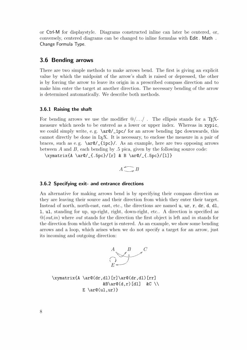
3.6.2 Specifying exit- and entrance directions
An alternative for making arrows bend is by specifying their compass direction asthey are leaving their source and their direction from which they enter their target.Instead of north, north-east, east, etc., the directions are named u, ur, r, dr, d, dl,l, ul, standing for up, up-right, right, down-right, etc.. A direction is specified as@(out,in) where out stands for the direction the first object is left and in stands forthe direction from which the target is entered. As an example, we show some bendingarrows and a loop, which arises when we do not specify a target for an arrow, justits incoming and outgoing direction:
A @@ <<B
oo
C
E��
\xymatrix{A \ar@(dr,dl)[r]\ar@(dr,dl)[rr]
&B\ar@(d,r)[dl] &C \\
E \ar@(ul,ur)}
8

3.7 Modifying vertices
The above example is reminiscent of an automata diagram, except that in such adiagram states would be enclosed in small circles, with double circles denoting finalstates.
3.7.1 Framing objects
With XY-pic, entries can obtain a single or a double frame, such as A or B byprefixing an entry with *[F-] or *[F=] and enclosing the portion of the entry to beframed in braces. Normally, the frame will be very tight so that it must be widened
by prefixing with + or with ++. Round frames, such as GFED@ABCA and GFED@ABC?>=<89:;B are obtained by
specifying the shape as [o]. So the latter figure was constructed as *++[o][F=]{B}.This way, the following automaton
start // ?>=<89:;1 // ?>=<89:;765401232 ii
can be typeset as
\xymatrix{\txt{start}\ar[r]
& *++[o][F]{1}\ar[r]
& *++[o][F=]{2}\ar@(ur,dr)\ar@(ur,ul)[l]
}.
The LATEX command \entrymodifiers={. . . } will make a certain entry style the de-fault, that can, of course be overridden for individual entries. Thus, after \entrymodifiers={++[o][F-]}, all following entries inside XY-matrices would be encircled.
3.7.2 Framing rectangles
Framing a whole rectangle inside an xymatrix is done with the macro pair \save
... \restore. The dimension of the rectangle is given as a dotted pair P0.P1 ofpoints denoting the top left and lower right corners of the rectangle. Each point, inturn,is given as a doubly quoted comma separated pair “x, y” specifying row x andcolumn y. These are followed by the framing commands, to produce figures such asthe following:
A B
φ
ψooC
Here, the code \save"1,1"."2,1"*+[F=]\frm{}\restore produces the doubly framedrectangle, and the code for the extra wide horizontal rectangle is \save"1,1"."1,2"*++[F]\frm{}\restore.This code can be placed in arbitrary cells of the xymatrix.
9

4 Using LYX’s math editor
As an alternative to writing the xypic code, then transforming it into a math-editingenvironment by marking it and applying Ctrl-m, or Ctrl-M, one may construct andmodify the whole xypic-diagram inside LYX’s math editor. We describe the editingsteps for a figure just like the one above.
4.1 Caveat - how to enter braces
Recall that in LYX’s math-editor any pair of braces { and } that are to enclose amacro-parameter must be entered by typing just \{ . The closing brace is auto-matically supplied and in between a box into which to the parameter is entered. Inconnection with XY-diagrams, this applies in particular to arrow modifications thatare normally given in the form @{ . . . } with the ellipsis standing for the descriptionof end, shaft and tip of the arrow. Inside the math-editor, enter just @\{ and letLYX provide the closing brace and the box into which to enter the description of thearrow.
Braces that are entered without the backslash \ will just appear as typed, butcannot be used to receive a macro parameter. They are useful, for instance to denotesets, e. g. {x\in X \mid x\notin x} will display as {x ∈ X | x /∈ x}.
4.2 Setting up the matrix
With Ctrl-m or Ctrl-M open a formula environment and enter: \xymatrix. Thisproduces a 1×1- XY-matrix. Add extra rows by typing Ctrl-Enter and add columnsby typing Alt-m c i.
At any time, further rows or columns can be entered or deleted using commandsavailable from Edit .Math, resp. their shortcuts, beginning with Alt-m c for thecolumn commands or Alt-m w for the row commands. A more direct way uses theicons in the math toolbar once it has been activated via View .Toolbars.
4.3 Entering nodes, arrows and labels
Type the nodes into the correct positions of the matrix. If you move the cursor out ofthe matrix, you should see a first rendering of the node layout. Next, add the arrowsat the nodes from where they should emanate by typing \ar[p], where p can be anypath made up from the characters u, d, l, r. Make sure that the path indeed leadsto an existing node within the matrix. Otherwise, the figure will not display whenthe cursor leaves the editing area.
Next, label the arrows by attaching a label text as upper or lower indices to theend of the arrow’s path. As always in LYX’s math editor, an underscore _ opens abox for a lower index and a ^ followed by a space opens a box for an upper index.You can enter any LATEX-code as a label.
10

4.4 Modifying arrows
Finally, you can modify the appearance of the arrows by entering @-modifiers @{. . . },@<. . .>, @(. . . ,. . . ) or @/. . . /. The above caveat applies to the first form only. Itmust be entered as @\{ with the arrow description entered inside the LYX-suppliedbox. If this box remains empty, you have specified an empty arrow. This is a usefulconstruction, too, as you will see in the next section.
The other modifiers, @<. . . >, @(. . . ,. . . ) and @/. . . / are typed as shown withthe arrow description replacing the ellipsis. The code for bending arrows, whichin xypic is @/_measure/ or @/^measure/ where measure is any valid TEX-measurethat should be entered as upper or lower index to the first slash /. Make sure thatthe ending slash does not end up being part of the upper or lower index.
4.5 What if something goes wrong
When constructing a diagram, you should at times check it by just moving the cursorout of the editing area to see whether instant preview can successfully convert it intographical output. If this does not happen, it may either be that instant preview forsome reason is not aware that it should retranslate the graphics. Moving the cursorinto the editing area and out again sometimes wakes up instant preview.
A more serious reason could be a syntactical error in your input (in that case, themath edition area disappears completely). If necessary, undo the last editing steps,using Ctrl+Z, or try to translate the LYX-file into DVI using Ctrl+D or View .DVI.There should be some error generated, which hopefully gives you a hint as to thesource of the mistake.
5 Hacks
Certain things do not work correctly inside LYX. The ones that we (used to) missmost are the horizontal and vertical scaling of diagrams, and the correct positioningof arrows. There are some workarounds that we are explaining here.
5.1 Horizontal and vertical scaling
It is often convenient to stretch the horizontal or the vertical dimensions of an entirediagram by using spacing commands for rows and/or columns. According to the XY-manual, for instance, \xymatrix@R=1pc{. . . } defines anXY-matrix with row spacing of1 pica. Similarly, \xymatrix@C=. . . {. . . } allows to modify the space between columns.Unfortunately, these commands do currently not work inside LYX, as the @-characteris interpreted by LYX as ending the XY-matrix-macro.
Knowing that XY stores the values for row-spacing and column-spacing in thevariables \xymatrixrowsep@ and \xymatrixrowsep@, add the following macro tothe preamble (Layout .Document .Preamble):
11

\newcommand{\xyR}[1]{%
\xydef@\xymatrixrowsep@{#1}}
A macro \xyC can be defined correspondingly by replacing \xymatrixrowsep@ with\xymatrixcolsep@. Now, a figure can be scaled by entering \xyR{...} into the XY-matrix. Place the cursor inside the matrix, just before the first entry. Then enter\xyR\{ or \xyC\{ or both. Don’t forget the backslashes and remember, that theclosing brace is automatically supplied by LYX. Inside the braces enter the dimen-sions. The default is 2pt. Here you see a diagram which is squashed vertically andstretched horizontally with \xyR{9pc}\xyC{.5pc}:
A //
��
B
C
horizontal stretch
5.2 Label positioning
Another useful XY-command allows the correct positioning of labels along the shaftof arrows. This feature is sometimes necessary, when the default position of a labelwould otherwise clutter the picture, or would even coincide with other items, such asthe intersection of the arrows in the figure below. In order to shift a label positionalongside the shaft of an arrow, XY allows to prefix the label by a decimal number inparentheses, specifying the fraction of distance alongside the arrow where the label isto be placed. For instance, the code \ar[r]|(0.3)\varphi, will place the label onthe shaft, but only about one third of the way.
Doing the same with labels above or below arrows as \ar[dr]^(0.3)\varphi, re-spectively \ar[ur]_(0.3)\phi, does not work from inside LYX. Instead, one has toreplace the hat-symbol ˆ, resp. the underscore , by the macros \sp, resp. \sb, ob-taining \ar[dr]\sp(0.3)\varphi and \ar[ur]\sb(0.3)\phi. It is, in fact, pos-sible to enter several labels this way and those labels are placed correctly, even ifthe arrow bends. In the following figure, the bending arrow with its four labelshas been produced with \ar@(r,r)[d] \sp(0.2){\phi_{1}} \sp(0.4){\phi_{2}}
\sb(0.6){\phi_{3}} \sp(0.8){\phi_{4}}.
• ϕ
&&LLLLLLLLLLLL ◦...
φ1
φ2φ3
φ4qq◦ φ
88rrrrrrrrrrrr •
5.3 Invisible stretched arrows
A more general trick uses invisible arrows to place any object almost anywhere insidea diagram. Produce an invisible arrow, shorten (or prolong) it past its goal by addinga decimal stretching ratio, e. g. (0.6) or (1.4) to its path. Attach a label to thisinvisible arrow.
12

Thus, the down pointing arrow with its label ϕ at (0.3) of its way along the shaftmight as well have been produced by adding to the regular arrow \ar[dr] an invisibleϕ-labelled arrow \ar@{}[dr(0.6)]^\varphi, reaching only 0.6 of the way. Its labelwill now appear at 0.3 of the way of the original visible arrow.
This workaround has two minor drawbacks: First, it does not work with bendingarrows. Secondly, prolonging an invisible arrow beyond the normal dimension of thefigure will invisibly extend the figure box, and thereby cause too much vertical spacebetween the figure and the preceding or the following paragraph.
Nevertheless, invisible arrows are an important tool, since they can, in principle,be used to place information at any chosen place in a diagram. In the above figure,for instance, we have used an invisible arrow to carry the \vdots as label and at theearlier figure we had used an invisible arrow to carry the text “horizontal stretch”into the center of the figure.
5.4 Further XY-tricks
Here we have focused only on the \xymatrix command, which is just one of the fea-tures available in Kris Rose’s amazing XY-package. The XY-pic manual [1] demonstratesmany of the advanced possibilities of that package. Beware, that its style is ratherterse and you will likely need a lot of experimenting and modifying the many workedexamples. Lauda [5] explains how to use XY-pic to make braids, cobordism, stringdiagrams, and much more. You might want to look on inset_preview.lyx exam-ple shipped with LYX, which demonstrates how to use more advanced XY-commandsvia ERT and Instant preview insets. A good and rather systematic introduction toXY-matrix is [6]. Even if you share with me the disadvantage of not being fluent inEsperanto, you will be able to understand most of it.
References
[1] Kristoffer H. Rose: XY-pic User’s Guide. Version 3.7, Feb. 16, 1999.Available as part of the xypic LATEX package.
[2] http://www.tug.org/tex-archive/help/Catalogue/entries/
preview-latex.html
[3] http://www.tug.org/tex-archive/help/Catalogue/entries/
xypic.html
[4] http://www.gnu.org/software/auctex/
[5] Aarlon Lauda: XY-pic tutorial with an archive of examples.http://www.math.columbia.edu/~lauda/xy/
[6] Filipp Ouvaton: XY-pic: Enkonduko pri Xymatrix. http://filip.
ouvaton.org/xypic/xymatrix/index.html
13


