Embed Size (px)
DESCRIPTION
■ After reading this manual, keep it in the place that the user always can contact easily. To prevent injury and property damage, follow these instructions. Incorrect operation due to ignoring instructions will cause harm or damage. The seriousness of which is indicated by the following symbols. ■ This manual should be given to the person who actually uses the products and is responsible for their maintenance. This symbol indicates the possibility of death or serious injury I
Citation preview

I
Thank you for purchasing LS Variable Frequency Drives!
SAFETY INSTRUCTIONS
To prevent injury and property damage, follow these instructions. Incorrect operation due to ignoring instructions will cause harm or damage. The seriousness of which is indicated by the following symbols.
DANGER
WARNING
CAUTION
This symbol indicates the possibility of death or serious injury
This symbol indicates the possibility of injury or damage to property
This symbol indicates the instant death or serious injury if you don’t follow instructions
■ The meaning of each symbol in this manual and on your equipment is as follows.
This is the safety alert symbol. Read and follow instructions carefully to avoid dangerous situation.
This symbol alerts the user to the presence of “dangerous voltage” inside the product that might cause harm or electric shock.
■ After reading this manual, keep it in the place that the user always can contact easily.
■ This manual should be given to the person who actually uses the products and is responsible for their maintenance.

II
WARNING
n Do not remove the cover while power is applied or the unit is in operation. Otherwise, electric shock could occur.
n Do not run the inverter with the front cover removed. Otherwise, you may get an electric shock due to high voltage terminals or charged capacitor exposure.
n Do not remove the cover except for periodic inspections or wiring, even if the input power is not applied. Otherwise, you may access the charged circuits and get an electric shock.
n Wiring and periodic inspections should be performed at least 10 minutes after disconnecting the input power and after checking the DC link voltage is discharged with a meter (below DC 30V). Otherwise, you may get an electric shock.
n Operate the switches with dry hands. Otherwise, you may get an electric shock.
n Do not use the cable when its insulating tube is damaged. Otherwise, you may get an electric shock.
n Do not subject the cables to scratches, excessive stress, heavy loads or pinching. Otherwise, you may get an electric shock.

III
CAUTION
n Install the inverter on a non-flammable surface. Do not place flammable material nearby.
Otherwise, fire could occur.
n Disconnect the input power if the inverter gets damaged. Otherwise, it could result in a secondary accident and fire.
n Do not touch the inverter while the input power is applied or after removed. It will remain hot for a couple of minutes. Otherwise, you may get bodily injuries such as skin-burn or damage.
n Do not apply power to a damaged inverter or to an inverter with parts missing even if the installation is complete. Otherwise, electric shock could occur.
n Do not allow lint, paper, wood chips, dust, metallic chips or other foreign matter into the drive. Otherwise, fire or accident could occur.
OPERATING PRECAUTIONS
(1) Handling and installation
¨ Handle according to the weight of the product.
¨ Do not stack the inverter boxes higher than the number recommended.
¨ Install according to instructions specified in this manual.
¨ Do not open the cover during delivery.
¨ Do not place heavy items on the inverter.
¨ Check the inverter mounting orientation is correct.
¨ Do not drop the inverter, or subject it to impact.
¨ Use the ground impedance of 100ohm or less for 200 V Class and 10ohm or less for
400V class.
¨ Take protective measures against ESD (Electrostatic Discharge) before touching the
pcb for inspection or installation.
¨ Use the inverter under the following environmental conditions:
IV
Ambient temp.
- 10 ~ 40 ℃ (non-freezing)
Relative
humidity
90% RH or less (non-condensing)
Storage
temp.
- 20 ~ 65 ℃
Location Protected from corrosive gas, combustible gas, oil mist
or dust
Altitude,
Vibration
Max. 1,000m above sea level, Max. 5.9m/sec2 (0.6G) or
less
En
viron
men
t
Atmospheric pressure
70 ~ 106 kPa
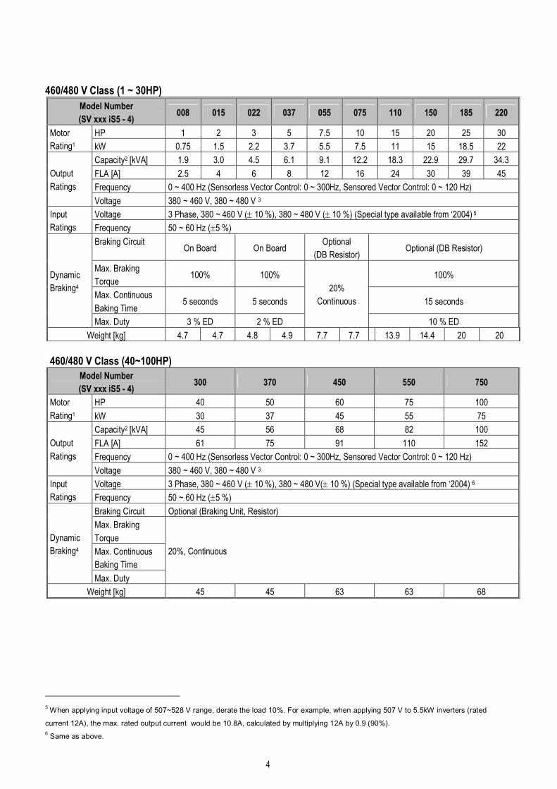
(2) Wiring
¨ Do not connect a power factor correction capacitor, surge suppressor, or RFI filter to
the output of the inverter.
¨ The connection orientation of the output cables U, V, W to the motor will affect the
direction of rotation of the motor.
¨ Incorrect terminal wiring could result in the equipment damage.
¨ Reversing the polarity (+/-) of the terminals could damage the inverter.
¨ Only authorized personnel familiar with LS inverter should perform wiring and
inspections.
¨ Always install the inverter before wiring. Otherwise, you may get an electric shock or
have bodily injury.
(3) Trial run
¨ Check all parameters during operation. Changing parameter values might be required
depending on the load.
¨ Always apply permissible range of voltage to the each terminal as indicated in this
manual. Otherwise, it could lead to inverter damage.
(4) Operation precautions
¨ When the Auto restart function is selected, stay away from the equipment as a motor
will restart suddenly after an alarm stop.
¨ The Stop key on the keypad is valid only when the appropriate function setting has
been made. Prepare an emergency stop switch separately.
¨ If an alarm reset is made with the reference signal present, a sudden start will occur.
Check that the reference signal is turned off in advance. Otherwise an accident could
occur.
¨ Do not modify or alter anything inside the inverter.
¨ Motor might not be protected by electronic thermal function of inverter.
¨ Do not use a magnetic contactor on the inverter input for frequent starting/stopping of
the inverter.
¨ Use a noise filter to reduce the effect of electromagnetic interference. Otherwise
nearby electronic equipment may be affected.

V
¨ In case of input voltage unbalance, install AC reactor. Power Factor capacitors and
generators may become overheated and damaged due to potential high frequency
noise transmitted from inverter.
¨ Use an insulation-rectified motor or take measures to suppress the micro surge voltage
when driving 400V class motor with inverter. A micro surge voltage attributable to
wiring constant is generated at motor terminals, and may deteriorate insulation and
damage motor.
¨ Before operating unit and prior to user programming, reset user parameters to default
settings.
¨ Inverter can easily be set to high-speed operations, Verify capability of motor or
machinery prior to operating unit.
¨ Stopping torque is not produced when using the DC-Break function. Install separate
equipment when stopping torque is needed.
(5) Fault prevention precautions
¨ Provide a safety backup such as an emergency brake which will prevent the machine
and equipment from hazardous conditions if the inverter fails.
(6) Maintenance, inspection and parts replacement
¨ Do not conduct a megger (insulation resistance) test on the control circuit of the
inverter.
¨ Refer to Chapter 8 for periodic inspection (parts replacement).
(7) Disposal
¨ Handle the inverter as an industrial waste when disposing of it.
(8) General instructions
Many of the diagrams and drawings in this instruction manual show the inverter without a circuit
breaker, a cover or partially open. Never run the inverter like this. Always place the cover with
circuit breakers and follow this instruction manual when operating the inverter.

VI
(9) UL Marking
1. Short Circuit Rating
“Suitable For Use On A Circuit Capable Of Delivering Not More Than Table1 RMS Symmetrical
Amperes, 240V for 240V rated inverters, 480V for 480V rated inverters Volts Maximum,”
Table 1. RMS Symmetrical Amperes for iS5 series.
Model Rating
SV008iS5-2, SV008iS5-4, SV015iS5-2, SV015iS5-4, SV022iS5-2, SV022iS5-4,
SV037iS5-2, SV037iS5-4,SV055iS5-2, SV055iS5-4, SV075iS5-2, SV075iS5-4,
SV110iS5-2, SV110iS5-4, SV150iS5-2, SV150iS5-4,SV185iS5-2, SV185iS5-4,
SV220iS5-2, SV220iS5-4, SV3005iS5-2, SV300iS5-4, SV370iS5-2, SV370iS5-4
5,000A
SV450iS5-2, SV450iS5-4, SV550iS5-2, SV550iS5-4, SV750iS5-4, 10,000A
2. OVERLOAD PROTECTION
IOLT: IOLT(inverter Overload Trip) protection is activated at 150% of the inverter rated current for
1 minute and greater.
OLT : Inverter shuts off its output when inverter output current exceeds its overload trip level for
overload trip time. OLT is selected when FU1-56 is set to “Yes” and activated at 120% of FU1-57
[Motor rated current] for 60 sec set in FU1-58.
3. OVER SPEED PROTECTION
“Not Provided With Overspeed Protection”.
4.Risk of Electric Shock
More than one disconnect switch may be required to de-energize the equipment before servicing.

1
CONTENTS
SAFETY INSTRUCTIONS I
USER SELECTION GUIDE (IS5 SPECIFICATIONS).......................................................................................... 3
CHAPTER 1 - INSTALLATION ........................................................................................................................ 6
1.1 Inspection.............................................................................................................................................................. 6
1.2 Environmental Conditions.................................................................................................................................. 6
1.3 Mounting................................................................................................................................................................ 6
1.4 Other Precautions ................................................................................................................................................ 7
1.5 Dimensions ........................................................................................................................................................... 8
1.6 Basic Wiring ........................................................................................................................................................13
1.7 Power Terminals.................................................................................................................................................14
1.8 Control Terminals...............................................................................................................................................19
CHAPTER 2 - OPERATION ........................................................................................................................... 23
2.1 Parameter Groups..............................................................................................................................................23
2.2 LCD Keypad ........................................................................................................................................................24
2.3 7-Segment Keypad.............................................................................................................................................28
2.4 Operation Method...............................................................................................................................................32
2.5 Operating Example.............................................................................................................................................33
CHAPTER 3 - VARIOUS FUNCTION SETTING & DESCRIPTION............................................................. 38
3.1 Function Setting .................................................................................................................................................38
3.2 Operation Example.............................................................................................................................................46
CHAPTER 4 - QUICK-START PROCEDURES............................................................................................. 51
4.1 Operating using keypad....................................................................................................................................52
4.2 Operation using Control Terminals.................................................................................................................53
4.3 Operation using Keypad and Control Terminals ..........................................................................................54
CHAPTER 5 - PARAMETER LIST................................................................................................................. 56
5.1 Drive Group [DRV]..............................................................................................................................................56
5.2 Function 1 Group [FU1].....................................................................................................................................58
5.3 Function 2 Group [FU2].....................................................................................................................................60
5.4 Input/Output Group [I/O] ...................................................................................................................................64
5.5 External Group [EXT].........................................................................................................................................70
5.6 Communication Group [COM]..........................................................................................................................74
5.7 Application Group [APP]...................................................................................................................................75
5.8 Sub-Board Selection Guide According To Function....................................................................................77
CHAPTER 6 - PARAMETER DESCRIPTION ............................................................................................... 79
6.1 Drive group [DRV] ..............................................................................................................................................79
6.2 Function 1 Group [FU1].....................................................................................................................................87
6.3 Function 2 Group [FU2].....................................................................................................................................99
6.4 Input/Output Group [I/O] .................................................................................................................................118
6.5 External Group [EXT].......................................................................................................................................136
6.6 Application Group [APP].................................................................................................................................145

2
CHAPTER 7 - OPTIONS ...............................................................................................................................153
7.1 Sub-A board.......................................................................................................................................................155
7.2 Sub-B Board ......................................................................................................................................................157
7.3 Sub-C Board (Isolated) ....................................................................................................................................161
7.4 Communication option boards.......................................................................................................................163
7.5 Keypad................................................................................................................................................................165
7.6 DB Resistors......................................................................................................................................................167
7.7 DB (Dynamic Brake) Unit.................................................................................................................................175
CHAPTER 8 - TROUBLESHOOTING & MAINTENANCE..........................................................................181
8.1 Fault Display......................................................................................................................................................181
8.2 Fault Remedy.....................................................................................................................................................183
8.3 Troubleshooting................................................................................................................................................185
8.4 How to Check Power Components................................................................................................................186
8.5 Maintenance ......................................................................................................................................................187
8.6 Daily and Periodic Inspection Items..............................................................................................................188
APPENDIX A - FUNCTIONS BASED ON USE ................................................................................................189
APPENDIX B - PARAMETERS BASED ON APPLICATION ..........................................................................190
APPENDIX C- PERIPHERAL DEVICES...........................................................................................................192
DECLARATION OF CONFORMITY..................................................................................................................194
3
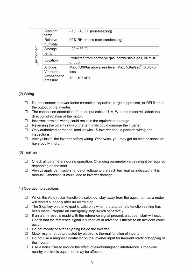
USER SELECTION GUIDE (iS5 SPECIFICATIONS)
230V Class (1 ~ 30HP)
Model Number
(SV xxx iS5 - 2) 008 015 022 037 055 075 110 150 185 220
HP 1 2 3 5 7.5 10 15 20 25 30 Motor
Rating1 kW 0.75 1.5 2.2 3.7 5.5 7.5 11 15 18.5 22
Capacity2 [kVA] 1.9 3.0 4.5 6.1 9.1 12.2 17.5 22.9 28.2 33.5
FLA [A] 5 8 12 16 24 32 46 60 74 88
Frequency 0 ~ 400 Hz (Sensorless Vector Control: 0 ~ 300Hz, Sensored Vector Control: 0 ~ 120 Hz)
Output
Ratings
Voltage 200 ~ 230 V 3
Voltage 3 Phase, 200 ~ 230 V (± 10 %) Input
Ratings Frequency 50 ~ 60 Hz (±5 %)
Braking Circuit On Board On Board Optional
(DB Resistor) Optional (DB Resistor)
Max. Braking
Torque 100% 100% 100%
Max. Continuous
Baking Time 5 seconds 5 seconds 15 seconds
Dynamic
Braking4
Max. Duty 3 % ED 2 % ED
20%,
Continuous
10 % ED
Weight [kg] 4.7 4.7 4.8 4.9 7.7 7.7 13.9 14.4 20 20
230V Class (40 ~ 75HP)
Model Number
(SV xxx iS5 - 2) 300 370 450 550
HP 40 50 60 75 Motor
Rating1 kW 30 37 45 55
Capacity2 [kVA] 46 55 68 84
FLA [A] 122 146 180 220
Frequency 0 ~ 400 Hz (Sensorless Vector Control: 0 ~ 300Hz, Sensored Vector Control: 0 ~ 120 Hz)
Output
Ratings
Voltage 200 ~ 230 V 3
Voltage 3 Phase, 200 ~ 230 V (± 10 %) Input
Ratings Frequency 50 ~ 60 Hz (±5 %)
Braking Circuit Optional (Braking Unit, Resistor)
Max. Braking
Torque
Max. Continuous
Baking Time
Dynamic
Braking4
Max. Duty
20%, Continuous
Weight [kg] 42 42 61 61
1 Indicates the maximum applicable capacity when using a 4-Pole LG motor.
2 Rated capacity (√3*V*I) is based on 220V for 200V class and 440V for 400V class.
3 Maximum output voltage will not be greater than the input voltage. Output voltage less than the input voltage may be programmed.
4 1~5 HP inverters have internal braking resistors as standard. 7.5~100 HP inverters utilize optional braking resistors.
4
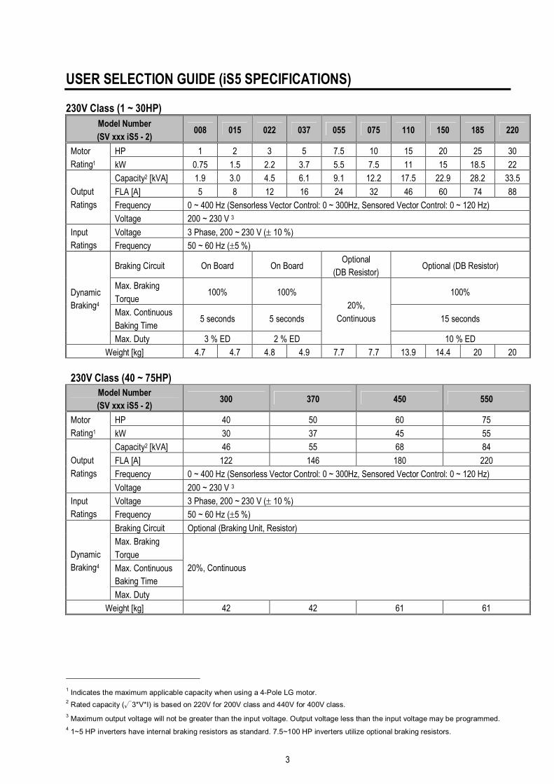
460/480 V Class (1 ~ 30HP)
Model Number
(SV xxx iS5 - 4) 008 015 022 037 055 075 110 150 185 220
HP 1 2 3 5 7.5 10 15 20 25 30 Motor
Rating1 kW 0.75 1.5 2.2 3.7 5.5 7.5 11 15 18.5 22
Capacity2 [kVA] 1.9 3.0 4.5 6.1 9.1 12.2 18.3 22.9 29.7 34.3
FLA [A] 2.5 4 6 8 12 16 24 30 39 45
Frequency 0 ~ 400 Hz (Sensorless Vector Control: 0 ~ 300Hz, Sensored Vector Control: 0 ~ 120 Hz)
Output
Ratings
Voltage 380 ~ 460 V, 380 ~ 480 V 3
Voltage 3 Phase, 380 ~ 460 V (± 10 %), 380 ~ 480 V (± 10 %) (Special type available from ‘2004) 5 Input
Ratings Frequency 50 ~ 60 Hz (±5 %)
Braking Circuit On Board On Board
Optional
(DB Resistor) Optional (DB Resistor)
Max. Braking
Torque 100% 100% 100%
Max. Continuous
Baking Time 5 seconds 5 seconds 15 seconds
Dynamic
Braking4
Max. Duty 3 % ED 2 % ED
20%
Continuous
10 % ED
Weight [kg] 4.7 4.7 4.8 4.9 7.7 7.7 13.9 14.4 20 20
460/480 V Class (40~100HP)
Model Number
(SV xxx iS5 - 4) 300 370 450 550 750
HP 40 50 60 75 100 Motor
Rating1 kW 30 37 45 55 75
Capacity2 [kVA] 45 56 68 82 100
FLA [A] 61 75 91 110 152
Frequency 0 ~ 400 Hz (Sensorless Vector Control: 0 ~ 300Hz, Sensored Vector Control: 0 ~ 120 Hz)
Output
Ratings
Voltage 380 ~ 460 V, 380 ~ 480 V 3
Voltage 3 Phase, 380 ~ 460 V (± 10 %), 380 ~ 480 V(± 10 %) (Special type available from ‘2004) 6 Input
Ratings Frequency 50 ~ 60 Hz (±5 %)
Braking Circuit Optional (Braking Unit, Resistor)
Max. Braking
Torque
Max. Continuous
Baking Time
Dynamic
Braking4
Max. Duty
20%, Continuous
Weight [kg] 45 45 63 63 68
5 When applying input voltage of 507~528 V range, derate the load 10%. For example, when applying 507 V to 5.5kW inverters (rated
current 12A), the max. rated output current would be 10.8A, calculated by multiplying 12A by 0.9 (90%). 6 Same as above.

5
Control Method V/F Control, Sensorless Vector Control, Sensored Vector Control (Velocity, Torque) Selectable
Frequency Setting
Resolution
Digital Reference: 0.01 Hz (Below 100 Hz), 0.1 Hz (Over 100 Hz)
Analog Reference: 0.03 Hz / 60 Hz
Frequency Accuracy Digital: 0.01 % of Max. Output Frequency
Analog: 0.1 % of Max. Output Frequency
V/F Ratio Linear, Squared Pattern, User V/F
Overload Capacity 150 % of Rated Current for 1 Min., 200% of Rated Current for 0.5 sec. (Characteristic is
Inversely Proportional to Time)
CO
NTR
OL
Torque Boost Manual Torque Boost (0 ~ 15 %), Auto Torque Boost
Operation Method Key / Terminal / Communication Operation
Frequency Setting Analog: 0 ~ 10V / 4 ~ 20mA / Additional port for Sub-Board (0 ~ 10V)
Digital: Keypad
Start Signal Forward, Reverse
Multi-Step Up to 8 Speeds can be Set (Use Multi-Function Terminal)
Multi Step Accel/Decel
Time
0 ~ 6,000 sec, Up to 4 Types can be Set and Selected for Each Setting (Use Multi- Function
Terminal). Accel/Decel Pattern: Linear, U-Curve, S-Curve
Emergency Stop Interrupts the Output of Inverter
Jog Jog Operation
Auto Operation Operates from Internal Sequence by Setting Multi-Function Terminal (5 Way * 8 Step)
Inpu
t Sig
nal
Fault Reset Trip Status is Removed when Protection Function is Active
Operating Status Frequency Detection Level, Overload Alarm, Stalling, Over Voltage, Under Voltage, Inverter
Overheating, Running, Stop, Constant Speed, Inverter By-Pass, Speed Searching, Auto-
Operation Step, Auto-Operation Sequence
Fault Output Contact Output (30A, 30C, 30B) – AC250V 1A, DC30V 1A
Out
put S
igna
l
Indicator Choose 1 from Output Frequency, Output Current, Output Voltage, DC Voltage, Output Torque
(Output Voltage: 0 ~ 10V)
OP
ER
ATI
ON
Operation Function DC Braking, Frequency Limit, Frequency Jump, Second Function, Slip Compensation, Reverse
Rotation Prevention, Auto Restart, Inverter By-Pass, Auto-Tuning, PID Control
Inverter Trip Over Voltage, Under Voltage, Over Current, Fuse Open, Ground Fault, Inverter Overheating,
Motor Overheating, Output Phase Open, Overload Protection, External Fault 1, 2,
Communication Error, Loss of Speed Command, Hardware Fault, Option Fault, Overspeed,
M/C Fail etc.
Inverter Alarm Stall Prevention, Overload Alarm, Temperature Sensor Fault
Pro
tect
ion
Momentary Power Loss Auto Restart function activated when FU2-21 [Restart after fault reset] set to 1 (Yes)
Operation
Information
Output Frequency, Output Current, Output Voltage, Frequency Value Setting, Operating
Speed, DC Voltage, Output Torque
Dis
play
Keypad
Trip Information Indicates a Fault when the Protection Function activates, Retains Up to 5 Faults
Ambient Temperature -10 °C ~ 40 °C (14 °F ~ 104 °F), CE Certification: 41 °F ~ 104 °F (5 °C ~ 40 °C)
Storage Temperature -20 °C ~ 65 °C (-4 °F ~ 149 °F)
Ambient Humidity Less Than 90 % RH Max. (Non-Condensing), CE Certification: 5 ~85% (Non-Condensing)
Altitude - Vibration Below 1,000m or 3,300ft · Below 5.9m/sec2 (=0.6g) Env
ironm
ent
Application Site No Corrosive Gas, Combustible Gas, Oil Mist, or Dust
Cooling Method Forced Air Cooling

6
CHAPTER 1 - INSTALLATION
1.1 Inspection l Inspect the inverter for any damage that may have occurred during shipping.
l Check the nameplate on the inverter. Verify the inverter unit is the correct one for the application. The numbering
system for the inverter is as shown below.
LS Inverter Motor Capacity Series Name Input Voltage
008: 1 HP 075: 10 HP 2: 200 ~ 230V (±10%) (50/60Hz)
015: 2 HP 110: 15 HP 4: 380 ~ 460V (±10%) (50/60Hz) UL Listed
022: 3 HP 150: 20 HP 4: 380 ~ 480V(±10%) (50/60Hz)
037: 5 HP 185: 25 HP
055: 7.5 HP 220: 30 HP N: Without Keypad
O/E: UL Open/Enclosed Type 1
DB: Built-in DB Unit
1.2 Environmental Conditions l Verify ambient condition for the mounting location.
- Ambient temperature should not be below 14ºF (-10ºC) or exceed 104ºF (40ºC).
- Relative humidity should be less than 90% (non-condensing).
- Altitude should be below 3,300ft (1,000m).
l Do not mount the inverter in direct sunlight and isolate it from excessive vibration.
l If the inverter is going to be installed in an environment with high probability of penetration of dust, it must be
located inside watertight electrical boxes, in order to get the suitable IP degree.
1.3 Mounting l The inverter must be mounted vertically with sufficient horizontal and vertical space between adjacent equipment
(A= Over 100mm, B= Over 50mm). However, A= Over 500mm and B= 200mm should be obtained for
inverters with 40Hp and above.
B
A
B
A
008 SV iS5 2 XXX U
…
(480)

Chapter 1 – Installation
7
1.4 Other Precautions
l Do not carry the inverter by the front cover.
l Do not install the inverter in a location where excessive vibration is present. Be cautious when installing on
presses or moving equipment.
l The life span of the inverter is greatly affected by the ambient temperature. Install in a location where temperature are within permissible limits (- 10 ~ 40 ℃).
l The inverter operates at high-temperatures - install on a non-combustible surface.
l Do not install the inverter in high-temperature or high-humidity locations.
l Do not install the inverter in a location where oil mist, combustible gas, or dust is present. Install the inverter in a
clean location or in an enclosed panel, free of foreign substance.
l When installing the inverter inside a panel with multiple inverters or a ventilation fan, use caution.
If installed incorrectly, the ambient temperature may exceed specified limits.
l Install the inverter using screws or bolts to insure the inverter is firmly fastened.
Inverter
GOOD (O) BAD (X)
Inverter
Cooling fan
Panel Panel
Inverter
Inverter
[When installing several inverters in a panel]
Ventilating fan
GOOD (O) BAD (X)
[When installing a ventilating fan in a panel]
UL Remark (File number: E124949): “Only intended for use in an enclosure with maximum surrounding air temperature of 45℃” or
equivalent: Models SV022iS5-2/4, SV037iS5-2/4, SV055iS5-4 (not -2), SV075iS5-4 (not -2), SV110iS5-2/4, SV150iS5-2/4, SV185iS5-2/4 and SV220iS5-2/4.
Chapter 1 – Installation
8
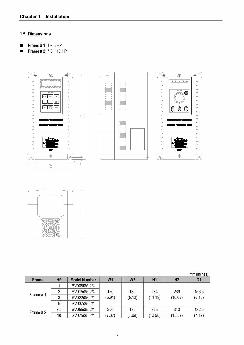
1.5 Dimensions
n Frame # 1: 1 ~ 5 HP
n Frame # 2: 7.5 ~ 10 HP
mm (inches)
Frame HP Model Number W1 W2 H1 H2 D1
1 SV008iS5-2/4
2 SV015iS5-2/4
3 SV022iS5-2/4 Frame # 1
5 SV037iS5-2/4
150
(5.91)
130
(5.12)
284
(11.18)
269
(10.69)
156.5
(6.16)
7.5 SV055iS5-2/4 Frame # 2
10 SV075iS5-2/4
200
(7.87)
180
(7.09)
355
(13.98)
340
(13.39)
182.5
(7.19)
Chapter 1 – Installation
9
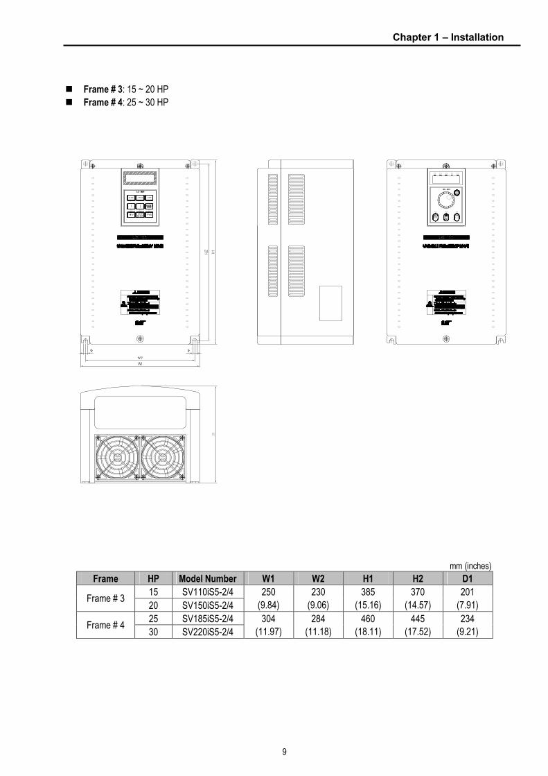
n Frame # 3: 15 ~ 20 HP
n Frame # 4: 25 ~ 30 HP
mm (inches)
Frame HP Model Number W1 W2 H1 H2 D1
15 SV110iS5-2/4 Frame # 3
20 SV150iS5-2/4
250
(9.84)
230
(9.06)
385
(15.16)
370
(14.57)
201
(7.91)
25 SV185iS5-2/4 Frame # 4
30 SV220iS5-2/4
304
(11.97)
284
(11.18)
460
(18.11)
445
(17.52)
234
(9.21)

Chapter 1 – Installation
10
n Frame # 5: 40~50HP
STARVERT-iS5
mm (inches)
Frame HP Model Number W1 W2 H1 H2 D1
40 SV300iS5-2/4 Frame # 5
50 SV370iS5-2/4
350
(13.78)
270
(10.63)
680
(28.77)
662
(26.06)
311
(12.25)

Chapter 1 – Installation
11
n Frame # 6: 60~75HP(200V)
STARVERT-iS5
mm (inches)
Frame HP Model Number W1 W2 H1 H2 D1
60 SV450iS5-2 Frame # 6
75 SV550iS5-2
397
(15.63)
275
(10.83)
780
(30.71)
760.5
(29.94)
330
(12.99)

Chapter 1 – Installation
12
n Frame # 7: 60~100HP (400V)
mm (inches)
Frame HP Model Number W1 W2 H1 H2 D1
60 SV450iS5-4
75 SV550iS5-4 Frame # 7
100 SV750iS5-4
375
(14.76)
275
(10.83)
780
(30.71)
760.5
(29.94)
330
(12.99)
STARVERT-iS5
Chapter 1 – Installation
13
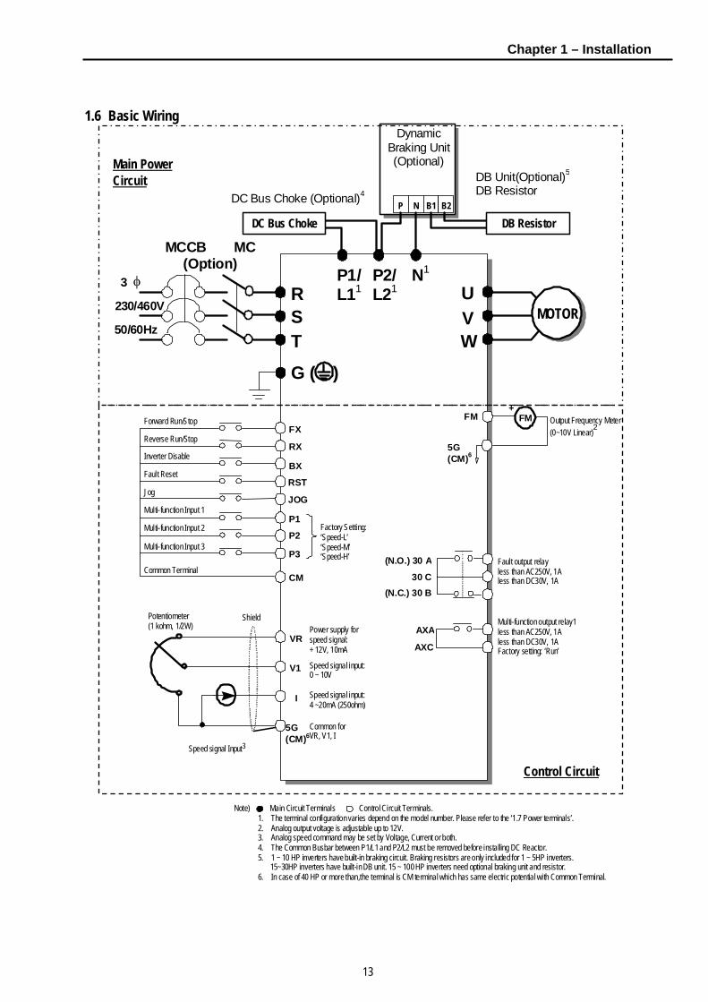
1.6 Basic Wiring
230/460V
50/60Hz
U V W
G ( )
R S T
N1
DB Unit(Optional)5
DB Resistor
φ 3
MCCB MC (Option)
FX
RX
BX
RST
P1
P3
CM
VR
V1
I
5G (CM)6
+ FM
5G (CM)6
(N.O.) 30 A
AXA
AXC
Output Frequency Meter (0~10V Linear)2
P2
MOTOR
Potentiometer (1 kohm, 1/2W)
Speed signal Input3
Forward Run/Stop
Reverse Run/Stop
Inverter Disable
Fault Reset
Multi-function Input 1
Multi-function Input 2
Multi-function Input 3
Common Terminal
Factory Setting: ‘Speed-L’ ‘Speed-M’ ‘Speed-H’
Power supply for speed signal: + 12V, 10mA
Speed signal input: 0 ~ 10V
Speed signal input: 4 ~20mA (250ohm)
Common for VR, V1, I
Fault output relay less than AC250V, 1A less than DC30V, 1A
Multi-function output relay1 less than AC250V, 1A less than DC30V, 1A Factory setting: ‘Run’
Note) Main Circuit Terminals Control Circuit Terminals. 1. The terminal configuration varies depend on the model number. Please refer to the ‘1.7 Power terminals’. 2. Analog output voltage is adjustable up to 12V. 3. Analog speed command may be set by Voltage, Current or both. 4. The Common Busbar between P1/L1 and P2/L2 must be removed before installing DC Reactor. 5. 1 ~ 10 HP inverters have built-in braking circuit. Braking resistors are only included for 1 ~ 5HP inverters.
15~30HP inverters have built-in DB unit. 15 ~ 100 HP inverters need optional braking unit and resistor. 6. In case of 40 HP or more than,the terminal is CM terminal which has same electric potential with Common Terminal.
P2/L21
P1/L11
DC Bus Choke (Optional)4
FM
DynamicBraking Unit(Optional)
P N B1 B2
DC Bus Choke DB Resistor
JOGJog
Shield
(N.C.) 30 B30 C
Main Power Circuit
Control Circuit

Chapter 1 – Installation
14
1.7 Power Terminals n Type A Configuration: 1 ~ 5 HP (230/460/480V)
R S T G N B1 B2 U V W
n Type B Configuration: 7.5 ~ 10 HP (230/460/480V)
R S T G P N B1 B2 U V W
n Type C Configuration: 15 ~ 30 HP (230/460/480V)
R S T G P1 P2 N U V W
n Type C Configuration: 15 ~ 30 HP (230/460/480V), Built-in DBU model
R S T G P1 B1 B2 U V W
n Type D Configuration: 40~ 75 HP (230V), 40 ~ 100 HP (460/480V)
R S T G U V W P1 P2 N
* Jumper should be removed to connect a DC reactor
Symbols Functions
R
S
T
AC Line Voltage Input
(3 Phase, 200 ~ 230VAC or 380 ~ 460/480 VAC)
G Earth Ground
P
Positive DC Bus Terminal
DB Unit (P-P7) Connection Terminals
(DB Unit may be added when more braking duty (More than 30%ED) is required)
P1
P2 External DC Reactor (P1-P2) and DB Unit (P2-N) Connection Terminals
N Negative DC Bus Terminal
DB Unit (N-N8) Connection Terminal
B1
B2 Dynamic Braking Resistor (B1-B2) Terminals for 1-30HP inverters
U
V
W
3 Phase Power Output Terminals to Motor
(3 Phase, 200 ~ 230VAC or 380 ~ 460/480 VAC)
“Suitable for use on a circuit capable of delivering not more than 10,000 rms symmetrical amperes,
240 volts maximum for 230V class models and 480 volts maximum for 460V class models.”
7 This P terminal is provided on optional Dynamic Braking Unit. 8 This N terminal is provided on optional Dynamic Braking Unit.
DB Resistor integrated
Chapter 1 – Installation
15
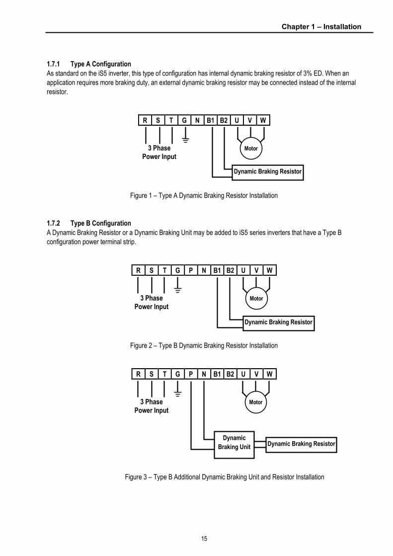
1.7.1 Type A Configuration
As standard on the iS5 inverter, this type of configuration has internal dynamic braking resistor of 3% ED. When an
application requires more braking duty, an external dynamic braking resistor may be connected instead of the internal
resistor.
R S T G N B1 B2 U V W
Figure 1 – Type A Dynamic Braking Resistor Installation
1.7.2 Type B Configuration
A Dynamic Braking Resistor or a Dynamic Braking Unit may be added to iS5 series inverters that have a Type B
configuration power terminal strip.
R S T G P N B1 B2 U V W
Figure 2 – Type B Dynamic Braking Resistor Installation
R S T G P N B1 B2 U V W
Figure 3 – Type B Additional Dynamic Braking Unit and Resistor Installation
Motor
Dynamic Braking Resistor
3 Phase Power Input
Motor 3 Phase Power Input
Dynamic Braking Resistor
Motor 3 Phase Power Input
Dynamic Braking Resistor Dynamic
Braking Unit

Chapter 1 – Installation
16
1.7.3 Type C Configuration
A Dynamic Braking Unit or a DC Bus Choke or both of them may be added to iS5 series inverters that have a Type A
Configuration power terminal strip.
Jumper Between P1 and P2 Must Be Removed in Order
to Install a DC Bus Choke.
R S T G P1 P2 N U V W
Figure 4 – Type C Dynamic Braking Unit, DC Bus Choke Installation
R S T G P1 B1 B2 U V W
Figure 5 – Type C Dynamic Braking Resistor
1.7.4 Type D Configuration
R S T G U V W P1 P2 N
Figure 6 – Type D Dynamic Braking Unit, DC Bus Choke Installation
Motor 3 Phase Power Input
Dynamic
Braking
Unit
DC Bus Choke (remove to
wire DC Reactor
Dynamic Braking Resistor
Motor 3 Phase Power Input
Dynamic Braking Resistor
Motor 3 Phase Power Input
Dynamic
Braking
Unit
DB Resistor
DC Bus Choke
(remove to wire DC Reactor)

Chapter 1 – Installation
17
1.7.5 Wiring Power Terminals
n Wiring Precautions
l The internal circuits of the inverter will be damaged if the incoming power is connected and applied to output
terminals (U, V, W).
l Use ring terminals with insulated caps when wiring the input power and motor wiring.
l Do not leave wire fragments inside the inverter. Wire fragments can cause faults, breakdowns, and malfunctions.
l For input and output, use wires with sufficient size to ensure voltage drop of less than 2%.
l Motor torque may drop of operating at low frequencies and a long wire run between inverter and motor.
l When more than one motor is connected to one inverter, total wire length should be less than 200m (656ft). Do
not use a 3-wire cable for long distances. Due to increased leakage capacitance between wires, over-current
protective feature may operate or equipment connected to the output side may malfunction. (But for products of
less than 3.7kW, the wire length should be less than 50m(146ft).) In case of long wire length, it should be required
to lower carrier frequency or use Micro Surge Filter.
Length between Inverter and Motor Up to 50m Up to 100m More than 100m
Allowable Carrier Frequency Less than 15kHz Less than 5kHz Less than 2.5kHz
l Connect only recommended braking resistor between the B1 and B2 terminals. Never short B1 and B2
terminals. Shorting terminals may cause internal damage to inverter.
l The main circuit of the inverter contains high frequency noise, and can hinder communication equipment near the
inverter. To reduce noise, install line noise filters on the input side of the inverter.
l Do not use power factor capacitor, surge killers, or RFI filters on the output side of the inverter. Doing so may
damage these components.
l Always check whether the LCD and the charge lamp for the power terminal are OFF before wiring terminals. The
charge capacitor may hold high-voltage even after the power is disconnected. Use caution to prevent the
possibility of personal injury.
n Grounding
l The inverter is a high switching device, and leakage current may flow. Ground the inverter to avoid electrical shock.
Use caution to prevent the possibility of personal injury.
l Connect only to the dedicated ground terminal of the inverter. Do not use the case or the chassis screw for
grounding.
l The protective earth conductor must be the first one in being connected and the last one in being disconnected. l As a minimum, grounding wire should meet the specifications listed below. Grounding wire should be as short as
possible and should be connected to the ground point as near as possible to the inverter.
Grounding wire Sizes, AWG (mm²) Inverter Capacity
200V Class 400VClass
Below 3.7kW (5HP) 12 (3.5) 14 (2)
5.5~7.5kW (7.5~10HP) 10 (5.5) 12 (3.5)
11~15kW (15~20HP) 6 (14) 8 (8)
18.5~22kW (25~30HP) 4 (22) 6 (14)
30~37kW (40~50HP) 4 (22) 6 (14)
45~75kW (60~100HP) 2 (38) 4 (22)
WARNING
Normal stray capacitance between the inverter chassis and the power devices inside the inverter and AC line can provide a high impedance shock hazard. Do not apply power to the inverter if the inverter frame (Power terminal G) is not grounded.

Chapter 1 – Installation
18
n Wires and Terminal Lugs
Refer to the following table for wires, terminal lugs, and screws used to connect the inverter power input (R, S, T) and
output (U, V, W). Input and motor output terminal blocks are intended only for use with ring type connectors.
Wire10
Ring Terminals mm² AWG Inverter Capacity
Terminal Screw Size
Screw Torque9
(Kgf·cm)/ lb-in
R,S,T U,V,W R,S,T U,V,W R,S,T U,V,W
0.75~2.2kW(1~3HP) M3.5 7.1~12.2 / 6.2~10.6 2-4 2-4 2 2 14 14
3.7 kW (5HP) M3.5 7.1~12.2 / 6.2~10.6 2-4 2-4 3.5 3.5 12 12
5.5 kW (7.5HP) M4 7.1~12.2 / 6.2~10.6 5.5-5 5.5-5 5.5 5.5 10 10
7.5 kW (10HP) M4 7.1~12.2 / 6.2~10.6 14-5 8-5 14 8 6 8
11 kW (15HP) M5 24.5~31.8 / 21.2~27.6 14-5 14-5 14 14 6 6
15 kW (20HP) M5 24.5~31.8 / 21.2~27.6 22-6 22-6 22 22 4 4
18.5 kW (25HP) M6 30.6~38.2 / 26.6~33.2 38-8 38-8 30 30 2 2
22 kW (30HP) M6 30.6~38.2 / 26.6~33.2 38-8 38-8 38 30 2 2
30~37 kW (40~50HP) M8 61.2~91.8 / 53.1~79.7 60-8 60-8 60 60 2/0 2/0
200V
Class
45~55 kW (60~75HP) M10 89.7~122.0 / 77.9~105.9 100-10 100-10 100 100 4/0 4/0
0.75~3.7 kW (1~5HP) M3.5 7.1~12.2 / 6.2~10.6 2-4 2-4 2 2 14 14
5.5 kW (7.5HP) M4 7.1~12.2 / 6.2~10.6 5.5-5 5.5-5 3.5 2 12 14
7.5 kW (10HP) M4 7.1~12.2 / 6.2~10.6 14-5 8-5 3.5 3.5 12 12
11 kW (15HP) M5 24.5~31.8 / 21.2~27.6 14-5 14-5 5.5 5.5 10 10
15 kW (20HP) M5 24.5~31.8 / 21.2~27.6 22-6 22-6 14 8 6 8
18.5 kW (25HP) M6 30.6~38.2 / 26.6~33.2 38-8 38-8 14 8 6 8
22 kW (30HP) M6 30.6~38.2 / 26.6~33.2 38-8 38-8 22 14 4 6
30~37 kW (40~50HP) M8 61.2~91.8 / 53.1~79.7 38-8 38-8 22 22 4 4
45~55 kW (60~75HP) M8 61.2~91.8 / 53.1~79.7 38-8 38-8 38 38 2 2
400V
Class
75 kW (100HP) M8 61.2~91.8 / 53.1~79.7 60-8 60-8 60 60 2/0 2/0
n Power and Motor Connection
R S T G N B1 B2 U V W
9 Apply the rated torque to terminal screws. Loose screws can cause of short circuit or malfunction. Tightening the screws too much
can damage the terminals and cause a short circuit or malfunction. 10
Use copper wires only with 600V, 75℃ ratings.
Motor 3 Phase Power Input
Power supply must be connected
to the R, S, and T terminals.
Connecting it to the U, V, and W
terminals causes internal damages
to the inverter. Arranging the phase sequence is not necessary.
Motor should be connected to the
U, V, and W terminals.
If the forward command (FX) is on,
the motor should rotate counter
clockwise when viewed from the load
side of the motor. If the motor rotates
in the reverse, switch the U and V
terminals.

Chapter 1 – Installation
19
1.8 Control Terminals
P1 P2 P3 FX RX NC VR V1
30A 30C 30B AXA AXC JOG CM CM BX RST I FM 5G
Type Symbol Name Description
P1, P2, P3 Multi-Function Input 1, 2, 3
Used for Multi-Function Input Terminal. (Factory default is set to “Multi-Step Frequency 1, 2, 3”.)
FX Forward Run Command Forward Run When Closed and Stopped When Open. RX Reverse Run Command Reverse Run When Closed and Stopped When Open.
JOG Jog Frequency Reference
Runs at Jog Frequency when the Jog Signal is ON. The Direction is set by the FX (or RX) Signal.
BX Emergency Stop
When the BX Signal is ON the Output of the Inverter is Turned Off. When Motor uses an Electrical Brake to Stop, BX is used to Turn Off the Output Signal. When BX Signal is OFF (Not Turned Off by Latching) and FX Signal (or RX Signal) is ON, Motor continues to Run.
RST Fault Reset Used for Fault Reset.
Star
ting C
ontac
t Fun
ction
Sele
ct
CM Sequence Common Common Terminal for Contact Inputs. NC - Not Used.
VR Frequency Setting Power (+12V)
Used as Power for Analog Frequency Setting. Maximum Output is +12V, 100mA.
V1 Frequency Reference (Voltage)
Used for 0-10V Input Frequency Reference. Input Resistance is 20 KΩ.
I Frequency Reference (Current)
Used for 4-20mA Input Frequency Reference. Input Resistance is 250 Ω.
Input
signa
l
Analo
g fre
quen
cy se
tting
5G11 Frequency Setting Common Terminal
Common Terminal for Analog Frequency Reference Signal and FM (For Monitoring).
Analo
g
FM Analog Output (0~12V) (For External Monitoring)
Outputs One of the Following: Output Frequency, Output Current, Output Voltage, DC Link Voltage, and Torque. Default is set to Output Frequency. Maximum Output Voltage and Output Current are 0-12V and 1mA, 500Hz.
30A 30C 30B
Fault Contact Output
Activates when Protective Function is Operating. AC250V, 1A or less; DC30V, 1A or less. Fault: 30A-30C Closed (30B-30C Open) Normal: 30B-30C Closed (30A-30C Open)
Outpu
t sign
al
Conta
ct
AXA, AXC Multi-Function Output Relay
Use After Defining Multi-Function Output Terminal. AC250V, 1A or less; DC30V, 1A or less.
* Tightening torque of control terminal blocks TER 1 – 140 Kgf·cm/(93.5 in-lb) TER 2 – 8 Kgf·cm/(5.3 in-lb)
11 In case of above 30kW, it is CM and it has a same electric potential with sequence common terminal CM.
Chapter 1 – Installation
20
1.8.1 Wiring Control Terminals
n Wiring Precautions
l CM and 5G terminals are insulated to each other. Do not connect these terminals with each other and do not
connect these terminals to the power ground. Terminal 5G is indicated as CM from 30kW inverters and has the
same potential as CM (Sequence Common Terminal).
l Use shielded wires or twisted wires for control circuit wiring, and separate these wires from the main power circuits
and other high voltage circuits.
l It is recommended to use the cables of 1.25 mm²(22 AWG) for connection to the control circuit terminals.
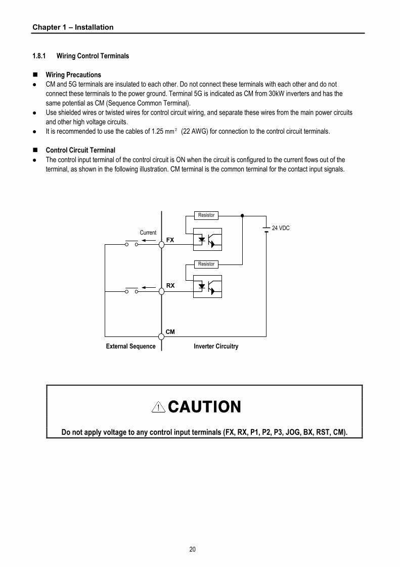
n Control Circuit Terminal
l The control input terminal of the control circuit is ON when the circuit is configured to the current flows out of the
terminal, as shown in the following illustration. CM terminal is the common terminal for the contact input signals.
CAUTION
Do not apply voltage to any control input terminals (FX, RX, P1, P2, P3, JOG, BX, RST, CM).
24 VDC
FX
RX
CM
Current
Inverter Circuitry
Resistor
Resistor
External Sequence
Chapter 1 – Installation
21
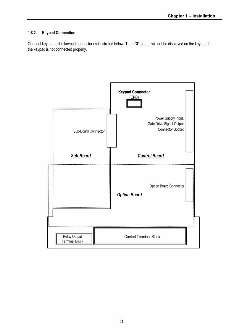
1.8.2 Keypad Connection
Connect keypad to the keypad connector as illustrated below. The LCD output will not be displayed on the keypad if
the keypad is not connected properly.
Control Board
Control Terminal Block Relay Output Terminal Block
Keypad Connector (CN3)
Sub-Board Connector
Power Supply Input,
Gate Drive Signal Output
Connector Socket
Option Board Connector
Sub-Board
Option Board

Chapter 1 – Installation
22
Notes:

23
CHAPTER 2 - OPERATION
The iS5 series inverter has seven parameter groups separated according to their applications as indicated in the
following table.
The iS5 series inverter provides two kinds of keypad. One is of 32-character alphanumeric LCD keypad and the other
is of 7-Segment LED keypad.
2.1 Parameter Groups
Parameter Group
LCD Keypad (Upper left Corner)
7-segment Keypad (LED is lit)
Description
Drive Group DRV ‘DRV’ LED Command Frequency, Accel/Decel Time etc.
Basic Parameters
Function 1 Group FU1 ‘FU1’ LED Max. Frequency, Amount of Torque Boost etc.
Basic Related Parameters
Function 2 Group FU2 ‘FU2’ LED Frequency Jumps, Max./Min. Frequency Limit etc.
Basic Application Related Parameters
Input / Output
Group I/O ‘I/O’ LED
Multi-Function Terminal Setting, Auto Operation etc.
Parameters needed for Sequence Operation
Sub-Board Group EXT ‘EXT’ LED Displayed when Sub-Board is Installed.
Option Group COM ‘I/O’ + ‘EXT’ LED Displayed when Option Board is Installed.
Application Group APP ‘FU2’ + ‘I/O’ + ‘EXT’
LED
Traverse, MMC (Multi-Motor Control), Draw etc.
Application Related Parameters
Refer to the function descriptions in chapter 6 for detailed description of each group.
Chapter 2 - Operation
24
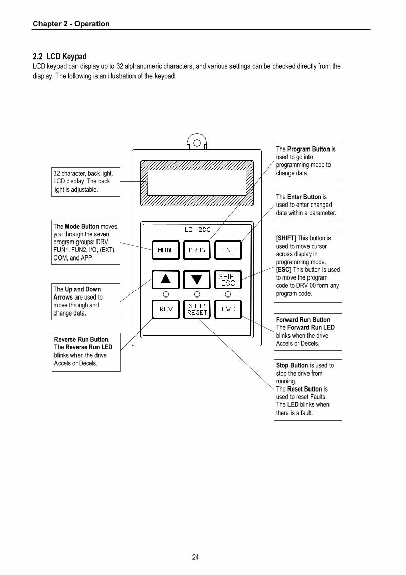
2.2 LCD Keypad LCD keypad can display up to 32 alphanumeric characters, and various settings can be checked directly from the
display. The following is an illustration of the keypad.
32 character, back light, LCD display. The back light is adjustable.
The Mode Button moves you through the seven program groups: DRV, FUN1, FUN2, I/O, (EXT), COM, and APP
The Up and Down Arrows are used to move through and change data.
Reverse Run Button. The Reverse Run LED blinks when the drive Accels or Decels.
The Program Button is used to go into programming mode to change data.
The Enter Button is used to enter changed data within a parameter.
[SHIFT] This button is used to move cursor across display in programming mode. [ESC] This button is used to move the program code to DRV 00 form any program code.
Forward Run Button The Forward Run LED blinks when the drive Accels or Decels.
Stop Button is used to stop the drive from running. The Reset Button is used to reset Faults. The LED blinks when there is a fault.

Chapter 2 - Operation
25
2.2.1 LCD Keypad Display
DRV▶T/K 0.0 A00 STP 0.00 Hz
Displays Description
1) Parameter Group Displays the parameter group. There are DRV, FU1, FU2, I/O, EXT, COM, APP groups.
2) Run/Stop Source Displays the source of motor Run and Stop
K: Run/Stop using FWD, REV buttons on keypad
T: Run/Stop using control terminal input FX, RX
O: Run/Stop via option board
3) Frequency Setting
Source
Displays the source of command frequency setting
K: Frequency setting using keypad
V: Frequency setting using V1 (0 ~10V) or V1 + I terminal
I: Frequency setting using I (4 ~ 20mA) terminal
U: Up terminal input when Up/Down operation is selected
D: Down terminal input when Up/Down operation is selected
S: Stop status when Up/Down operation is selected
O: Frequency setting via Option board
X: Frequency setting via Sub board
J: Jog terminal input
1 ~ 8: Step frequency operation
* During Auto operation, 2) and 3) display the ‘sequence number/step’.
4) Output Current Displays the Output Current during operation.
5) Parameter Code Displays the code of a group. Use the ▲(Up), ▼(Down) key to move through 0~99 codes.
6) Operating Status Displays the operation information.
STP: Stop Status
FWD: During Forward operation
REV: During Reverse operation
DCB: During DC Braking
LOP: Loss of Reference from Option Board (DPRAM fault)
LOR: Loss of Reference from Option Board (Communication network fault)
LOV: Loss of Analog Frequency Reference (V1: 0~10V)
LOI: Loss of Analog Frequency Reference (I: 4~20mA)
LOS: Loss of Reference from Sub-Board
7) Drive Output Frequency
Command Frequency
Displays the Output Frequency during run.
Displays the Command Frequency during stop.
2) Run/Stop Source 3) Frequency Setting Source
4) Output Current
7) Drive Output Frequency During Run,
Command Frequency During Stop 6) Operating Status
5) Parameter Code
1) Parameter group

Chapter 2 - Operation
26
2.2.2 Procedure for Setting Data (LCD Keypad)
1. Press [MODE] key until the desired parameter group is displayed.
2. Press [▲] or [▼] keys to move to the desired parameter code. If you know the desired parameter code, you can
set the code number of each parameter group in “Jump code”, except DRV group.
3. Press [PROG] key to go into the programming mode, the cursor starts blinking.
4. Press [SHIFT/ESC] key to move the cursor to the desired digit.
5. Press [▲] or [▼] keys to change the data.
6. Press [ENT] key to enter the data. The cursor stops blinking.
n Note: Data cannot be changed when:
1) The parameter is not adjustable during the inverter is running. (Refer to the function table in Chapter 5) or
2) Parameter Lock function is activated in FU2-94 [Parameter Lock].

Chapter 2 - Operation
27
2.2.3 Parameter Navigation (LCD Keypad)
The parameter group moves directly to DRV group by pressing [SHIFT/ESC] key in any parameter code.
DRV▶T/K 0.0 A 00 STP 0.00 Hz
FU1▶ Jump code 00 1
FU2▶ Jump code 00 30
MODE
◀
FU1▶Run prohibit 03 None
FU2▶ Last trip-1 01 -------
I/O▶ V1 filter 01 10 ms
DRV▶ Dec. time 02 20.0 sec
FU1▶Acc. pattern 05 Linear
FU2▶ Last trip-2 02 -------
I/O▶ V1 volt x1 02 0.00 V
FU1▶Dec. pattern 06 Linear
FU2▶ Last trip-3 03 -------
I/O▶ V1 freq y1 03 0.00 Hz
DRV▶ Freq mode 04 KeyPad-1
FU1▶ Stop mode 07 Decel
FU2▶ Last trip-4 04 -------
I/O▶ V1 volt x2 04 10.00 V
DRV▶ Step freq-1 05 10.00 Hz
FU1▶ DcSt value 08 50 %
FU2▶ Last trip-5 05 -------
I/O▶ V1 freq y2 05 60.00 Hz
FU1▶ Stall Level 60 150 %
FU2▶ Para. lock 94 0
I/O▶ Way1 / 2D 60 Forward
MODE MODE MODE
MODE
I/O▶ Jump code 00 1
▶
MODE
◀
▶
MODE
◀
▶
MODE
◀
▶
MODE
◀
▶
◀
▶
◀
▶
◀
▶
◀
▶
◀
▶
◀
▶
◀
▶
◀
▶
◀
▶
◀
▶
◀
▶
◀
▶
◀
▶
◀
▶
◀
▶
◀
▶
◀
▶
◀
▶
DRV▶ Drive mode 03 Fx/Rx-1
DRV▶ Fault 12 -------
DRV▶ Acc. time 01 10.0 sec
MODE MODE MODE
MODE MODE MODE MODE
MODE MODE MODE MODE
MODE MODE MODE MODE
MODE MODE MODE MODE
◀
▶
Drive Group FU1 Group FU2 Group I/O Group
.
.
.
.
.
.
.
.
.
.
.
.

Chapter 2 - Operation
28
2.3 7-Segment Keypad
* Parameter Group Display LEDs – When parameter code is located on DRV 20, DRV 21, DRV 22 and DRV 23, respectively by
rotating the encoder knob, the parameter group display LEDs of DRV, FUN1, FUN2, I/O, EXT blink.
LED Parameter Group Description
DRV Drive Group Lit in Drive group.
FU1 FUNCTION 1 Group Blinks when the parameter code is located on DRV 20 [FUN1].
Lit when FUNCTION 1 group is selected.
FU2 FUNCTION 2 Group Blinks when the parameter code is located on DRV 21 [FUN2].
Lit when FUNCTION 2 group is selected.
I/O Input/Output Group Blinks when the parameter code is located on DRV 22 [I/O].
Lit when Input/Output group is selected.
EXT Sub-Board Group
Blinks when the parameter code is located on DRV 23 [EXT].
Lit when Sub-Board group is selected.
This group appears only when a Sub-Board is installed.
I/O + EXT Option Group
Blinks when the parameter code is located on DRV 24 [EXT].
Lit when Option group is selected.
This group appears only when an Option Board is installed.
FU2 + I/O + EXT Application Group Blinks when the parameter code is located on DRV 25 [FUN2].
7-segment display
Encoder knob
Used to move you
through parameter
groups and parameter
code. Also, used to
change data by rotating
knob.
Program Button is used to go into programming mode to change data. Enter Button is used to enter the changed data. The LED blinks during programming mode.
[SHIFT] This button is used to move cursor across display in programming mode. [ESC] This button is used to move the program code to DRV 00 from any program code.
Run Button is used to run the drive. The motor direction is set in DRV 13. The Run LED blinks when the drive Accels or Decels.
Stop Button is used to stop the drive from running. Reset Button is used to reset Faults. The LED blinks when there is a fault.
* Parameter Group Display LEDs.

Chapter 2 - Operation
29
2.3.1 7-Segment Keypad Display
Display Description
1) Parameter Group Displays the parameter groups of DRV, FU1, FU2, I/O, EXT, COM, APP groups.
Each LED is lit when its parameter group is selected and blinks when the parameter code is located on
DRV 20, DRV 21, DRV 22, DRV 23, DRV 24, and DRV 25.
2) Parameter Code and
Operating Status
Displays the code of a group. Rotate the encoder knob to move through 0 ~ 99 codes.
Displays the operation information.
[First digit]
F: Forward operation
r: Reverse operation
[Second digit]
d: DC Braking
J: Jog Terminal Input
1~8: Step Frequency Input (Displays the Step of the Auto operation)
[Two digits] - mark the reference is lost.
PL: Loss of Reference from the Option Board (DPRAM fault)
rL: Loss of Reference from the Option Board (Communication network fault)
vL: Loss of Analog Frequency Reference (V1: 0~10V)
IL: Loss of Analog Frequency Reference (I: 4~20mA)
XL: Loss of Reference from the Sub-Board
3) Output Frequency,
Command Frequency
Displays the Output Frequency during run.
Displays the Command Frequency during stop.
DRV FU1 I/OFU2 EXT
1) Parameter Group
3) Output Frequency during run,
Command Frequency during stop
2) Parameter Code and
Operating Status

Chapter 2 - Operation
30
2.3.2 Procedure for Setting Data (7-Segment Keypad)
n In DRV Group:
1. Rotate the encoder knob until the desired parameter code is displayed.
2. Press [PROG/ENT] key to go into the programming mode, then the display blinks.
3. Press [SHIFT/ESC] key to move the cursor to the desired digit.
4. Rotate the encoder knob to change the data.
5. Press [PROG/ENT] key to enter the changed data.
n In FUN1 Group:
1. Rotate the encoder knob until parameter code ‘20’ is displayed in drive group.
2. Press [PROG/ENT] key to go into the FUN1 group.
3. Rotate the encoder knob until the desired parameter code is displayed.
4. Press [PROG/ENT] key to go into the programming mode, then the display blinks.
5. Press [SHIFT/ESC] key to move the cursor to the desired digit.
6. Rotate the encoder knob to change the data.
7. Press [PROG/ENT] key to enter the changed data.
n In FUN2 Group:
1. Rotate the encoder knob until parameter code ‘21’ is displayed in drive group.
2. Go to step 2 of ‘In FUN1 Group’ above, and follow the rest procedure.
n In I/O Group:
1. Rotate the encoder knob until parameter code ‘22’ is displayed in drive group.
2. Go to step 2 of ‘In FUN1 Group’ above, and follow the rest procedure.

Chapter 2 - Operation
31
2.3.3 Parameter Navigation (7-Segment Keypad)
The parameter group moves directly to DRV group by pressing [SHIFT/ESC] key in any parameter code.
DRV FU1 I/OFU2 EXT
DRV FU1 I/OFU2 EXT
DRV FU1 I/OFU2 EXT
DRV FU1 I/OFU2 EXT DRV FU1 I/OFU2 EXT
DRV FU1 I/OFU2 EXT
DRV FU1 I/OFU2 EXT DRV FU1 I/OFU2 EXT
DRV FU1 I/OFU2 EXT
PROG ENT
DRV FU1 I/OFU2 EXT
DRV FU1 I/OFU2 EXT
DRV FU1 I/OFU2 EXT
Encoder Knob
FU1 Group
DRV Group
FU2 Group
I/O Group
PROG ENT
PROG ENT
SHIFT ESC
PROG ENT

Chapter 2 - Operation
32
2.4 Operation Method The iS5 has several operation methods as shown below.
Operation Method Function Function Setting
Operation using Keypad Run/Stop command and frequency are set only through the
keypad.
DRV 03: Keypad
DRV 04: Keypad-1 or -2
Operation using
Control Terminals
Closing FX or RX terminal performs Run/Stop.
Frequency reference is set through V1 or I or V1+I terminal.
DRV 03: Fx/Rx-1 or -2
DRV 04: V1 or I or V1+I
Run/Stop is performed by the keypad.
Frequency reference is set through the V1 or I or V1+I
terminal.
DRV 03: Keypad-1 or -2
DRV 04: V1 or I or V1+I
Operation using both
Keypad and Control
Terminals
Closing FX or RX terminal performs Run/Stop.
Frequency reference is set through the keypad.
DRV 03: Fx/Rx-1 or -2
DRV 04: Keypad-1 or -2
Operation using
Option Board
Operation using option board.
The iS5 has five option boards and three sub-boards.
Option Boards: RS485, Device-Net, F-Net, ProfiBus and
ModBus
Sub-Boards: Sub-A Board, Sub-B Board, Sub-C Board
(Please refer to ‘Chapter 7 - Options’ for more information.)

Chapter 2 - Operation
33
2.5 Operating Example
2.5.1 Operation via Control terminal + Keypad
1. Check the LCD display when Power ON. Otherwise, change the setting indicated above.
2. Turn the FX (or RX) terminal ON. Then FWD (or REV) LED will be lit.
3. When setting the Ref. Freq to 60 Hz using PROG/ENT/SHIFT, ▲ keys, motor will rotate at 60Hz.
FWD (or REV) LED will be flickering during Acceleration/ Deceleration.
4. Turn Fx (or Rx) terminal Off. Then Stop LED will be lit.
DRV▶T/K 0.0 A00 STP 0.00Hz
DRV▶T/K 0.0 A00 FWD 0.00Hz
DRV▶ Cmd. freq00 0.00Hz
DRV▶ Cmd. freq00 60.00Hz
DRV▶T/K 5.0 A00 FWD 60.00Hz
Note) To enable Run/Stop via keypad & Freq setting via control terminal…
Setting: DRV-03 [Drive Mode (Run/Stop method)] = 0 (Keypad)
DRV-04 [Frequency Mode (Freq. setting method)] = 2 (V1)
Setting: DRV-03 [Drive Mode (Run/Stop method)] = 1 (Fx/Rx-1)
DRV-04 [Frequency Mode (Freq. setting method)] = 0 (Keypad-1)
l With above setting, Freq setting via terminal & Run/Stop via Keypad disabled
DRV▶T/K 0.0 A00 STP 60.00Hz

Chapter 2 - Operation
34
Operation Example (1)
Freq Setting via Keypad + Run/Stop via Terminal (FX/RX)
[Operation condition]
-. Control mode: V/F control
-. Ref. Frequency: 50[Hz] setting via keypad
-. Accel/Decel time: Accel – 10 [Sec], Decel – 20 [Sec]
-. Drive mode: Run/Stop via FX/RX terminal
[Wiring]
R
S
T
G
U
V
W
B1 B2
FXRXBXRST
JOG P1P2P3CM
VRV15G
FM
5G
30A30C30B
AXAAXC
IM3PAC
input
Potentiometer1[kohm],1/2W
S/W
Step Parameter setting Code Description
1 Control Mode Selection FU2-39 Set it to 0 {V/F}.
2 Drive Mode DRV-3 Set it to 1 Fx/Rx-1.
3 Frequency Mode DRV-4 Set it to 0 Keypad-1.
4 50[Hz] freq command
setting DRV-0 Set freq command 50[Hz] via Keypad.
5 Accel/Decel time DRV-2 DRV-3
Set Accel time to 10 [Sec] in DRV-2. Set Decel time to 20 [Sec] in DRV-3.
6 Terminal FX
Motor starts to rotate in Forward direction at 50Hz with Accel time 10 [sec] when FX terminal is turned ON. Motor decelerates to stop with Decel time 25[sec] when FX terminal is turned OFF.
7 Terminal RX When RX terminal is turned ON motor starts to rotate in Reverse direction at 50[Hz] with Accel time 10 [Hz]. When it is OFF, motor decelerates to stop with Decel time 20 [Sec].

Chapter 2 - Operation
35
2.5.2 Operation via Control Terminal
1. Check the LCD display when Power ON. Otherwise, change the setting indicated above.
2. Turn the FX (or RX) terminal ON. Then FWD (or REV) LED will be lit.
3. Set the frequency using V1 (Potentiometer). Output freq (60Hz)., Rotating direction (FWD or REV) and output
current (5A) will be displayed on the LCD.
4. Output freq value is decreasing when turning the potentiometer counterclockwise. Inverter output stops at 0.00Hz
and motor is stopped.
5. Turn FX (or RX) terminal OFF.
Setting: DRV-03 [Drive Mode (Run/Stop method)] = 1 (Fx/Rx-1)
DRV-04 [Frequency Mode (Freq. setting method)] = 2 (V1)
DRV▶T/V 0.0 A00 STP 0.00Hz
DRV▶T/V 0.0 A00 FWD 0.00Hz
DRV▶T/V 5.0 A00 FWD 60.00Hz
DRV▶T/V 0.0 A00 FWD 0.00Hz
DRV▶T/V 0.0 A00 STP 0.00Hz
Chapter 2 - Operation
36
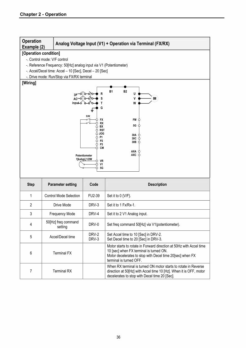
Operation Example (2)
Analog Voltage Input (V1) + Operation via Terminal (FX/RX)
[Operation condition]
-. Control mode: V/F control
-. Reference Frequency: 50[Hz] analog input via V1 (Potentiometer)
-. Accel/Decel time: Accel – 10 [Sec], Decel – 20 [Sec]
-. Drive mode: Run/Stop via FX/RX terminal
[Wiring]
R
S
T
G
U
V
W
B1 B2
FXRXBXRST
JOG P1P2P3CM
VRV15G
FM
5G
30A30C30B
AXAAXC
IM3PAC
input
Potentiometer1[kohm],1/2W
S/W
Step Parameter setting Code Description
1 Control Mode Selection FU2-39 Set it to 0 {V/F}.
2 Drive Mode DRV-3 Set it to 1 Fx/Rx-1.
3 Frequency Mode DRV-4 Set it to 2 V1 Analog input.
4 50[Hz] freq command
setting DRV-0 Set freq command 50[Hz] via V1(potentiometer).
5 Accel/Decel time DRV-2 DRV-3
Set Accel time to 10 [Sec] in DRV-2. Set Decel time to 20 [Sec] in DRV-3.
6 Terminal FX
Motor starts to rotate in Forward direction at 50Hz with Accel time 10 [sec] when FX terminal is turned ON. Motor decelerates to stop with Decel time 20[sec] when FX terminal is turned OFF.
7 Terminal RX When RX terminal is turned ON motor starts to rotate in Reverse direction at 50[Hz] with Accel time 10 [Hz]. When it is OFF, motor decelerates to stop with Decel time 20 [Sec].
Chapter 2 - Operation
37
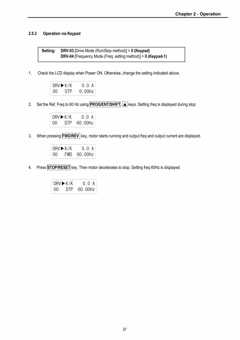
2.5.3 Operation via Keypad
1. Check the LCD display when Power ON. Otherwise, change the setting indicated above.
2. Set the Ref. Freq to 60 Hz using PROG/ENT/SHIFT, ▲ keys. Setting freq is displayed during stop.
3. When pressing FWD/REV key, motor starts running and output freq and output current are displayed.
4. Press STOP/RESET key. Then motor decelerates to stop. Setting freq 60Hz is displayed.
DRV▶K/K 0.0 A00 STP 0.00Hz
Setting: DRV-03 [Drive Mode (Run/Stop method)] = 0 (Keypad)
DRV-04 [Frequency Mode (Freq. setting method)] = 0 (Keypad-1)
DRV▶K/K 0.0 A00 STP 60.00Hz
DRV▶K/K 5.0 A00 FWD 60.00Hz
DRV▶K/K 0.0 A00 STP 60.00Hz
38
CHAPTER 3 - VARIOUS FUNCTION SETTING & DESCRIPTION
3.1 Function Setting
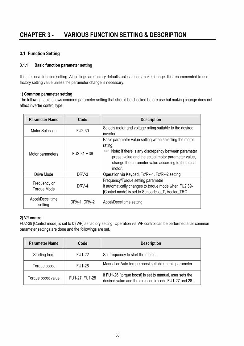
3.1.1 Basic function parameter setting
It is the basic function setting. All settings are factory defaults unless users make change. It is recommended to use
factory setting value unless the parameter change is necessary.
1) Common parameter setting
The following table shows common parameter setting that should be checked before use but making change does not
affect inverter control type.
Parameter Name Code Description
Motor Selection FU2-30 Selects motor and voltage rating suitable to the desired
inverter.
Motor parameters FU2-31 ~ 36
Basic parameter value setting when selecting the motor
rating.
☞ Note: If there is any discrepancy between parameter
preset value and the actual motor parameter value,
change the parameter value according to the actual
motor.
Drive Mode DRV-3 Operation via Keypad, Fx/Rx-1, Fx/Rx-2 setting
Frequency or
Torque Mode DRV-4
Frequency/Torque setting parameter
It automatically changes to torque mode when FU2 39-
[Control mode] is set to Sensorless_T, Vector_TRQ.
Accel/Decel time
setting DRV-1, DRV-2 Accel/Decel time setting
2) V/f control
FU2-39 [Control mode] is set to 0 (V/F) as factory setting. Operation via V/F control can be performed after common
parameter settings are done and the followings are set.
Parameter Name Code Description
Starting freq. FU1-22 Set frequency to start the motor.
Torque boost FU1-26 Manual or Auto torque boost settable in this parameter
Torque boost value FU1-27, FU1-28 If FU1-26 [torque boost] is set to manual, user sets the
desired value and the direction in code FU1-27 and 28.

Chapter 3 – Function Settings
39
3) V/F + PG control
If FU2-39 [control mode] is set to V/F with PG (encoder) feedback using SUB-B board, the control type is automatically
changed to V/F + PG. The following parameters should be set accordingly to enable PG feedback using SUB-B board.
Parameter Name Code Description
Usage of Pulse Input
Signal EXT-12
Defines the use of pulse input signal with SUB-B
mounted. This parameter should be set to 1 {Feed-back}.
Pulse Signal Input
Selection EXT-15
Three types of input signal settable;
(A+B), A, -(A+B)
Encoder Pulse
Number EXT-16 Defines the number of encoders of the motor.
P-Gain for ‘Sub-B’
I-Gain for ‘Sub-B’ EXT-22, EXT-23 PI gains for PI controller during PG operation
Slip Frequency for
‘Sub-B’ Board EXT-24 Set as a percent of FU2-32 [Rated Motor Slip].
4) Slip compensation
Operation is done via Slip compensation if FU2-39 is set to 1 {Slip compen}. This control keeps motor speed constant
regardless of load change.
5) Auto-tuning of motor constant
This parameter enables auto-tuning of the motor constants. If set to 1 {All mode}, tuning type varies according to what
control mode is set in [FU2-39]. Auto-tuning can be done in two ways – one is motor non-rotation mode, the other is
motor rotation mode.
① Auto-tuning by non-rotation mode: Rs+Lsigma
② Auto-tuning by rotation mode: All, Enc Test, Tr
Before performing Auto-tuning, set motor rating, motor parameter in common setting and select the desired control
mode in FU2-39 [control mode selection]. However, when auto-tuning parameters related to encoder, detail functions
settings of vector control should be pre-defined. If Enc Test, Tr and control mode are set to vector control, Sub-B board
should be mounted.
Parameter Name Code Description
Auto-tuning FU2-40 No, All, Rs+Lsigma, Enc Test, Tr
Parameter value
display
FU2-34,
FU2-41 ~ 44
Tuned value monitoring
(No-load current, stator/rotor resistance, leakage
inductance, rotor filter time constant)

Chapter 3 – Function Settings
40
FU2-40 Description
No Motor constants calculation disabled.
All
All constants can be measured in this code but different constants are tuned
according to control mode;
For V/F, Slip compen, Sensorless_S, Sensorless_T:
(No-load current, stator resistance, leakage inductance, stator inductance
available)
☞ Note: Only no-load current can be calculated during V/F and Slip
compensation.
For Vector_SPD, Vector_T:
(No-load current, stator resistance, leakage inductance, stator inductance,
encoder test, rotor filter time constant)
Rs+Lsigma Calculates stator resistance, leakage inductance.
Enc Test Calculates the encoder status.
Tr Calculates Rotor filter time constant.
6) Sensorless vector control
Set FU2-39 to 2 {Sensorless_S} or 3 {Sensorless_T} to enable Sensorless vector control. It is strongly recommended
to perform Auto-tuning for Sensorless before starting Sensorless control in order to maximize performance. Two types
of Sensorless vector control are available; Sensorless_S or Sensorless_T.
Parameter Name Code Description
Control mode selection FU2-39 Select Sensorless_S or Sensorless_T.
P, I gain for
sensorless control FU2-45, FU2-46 Set gain for Sensorless_S control.
Starting freq FU1-22 Starting freq of the motor
7) Vector control
Set FU2-39 to 4 {Vector_SPD} or 5 {Vector_TRQ} to enable Vector control. Encoder should be installed to the motor
with Sub-B board in the inverter to start this control.
Parameter Name Code Description
Usage of Pulse
Input Signal EXT-12
Defines the method of pulse input with SUB-B board
mounted. Vector control setting is valid only after this
parameter is set to 1 {Feed-back}.
Pulse Input Signal
Selection EXT-15
3 types of pulse input: (A+B), A, -(A+B)
Encoder Pulse Number EXT-16 Enters the pulse number of encoder in the motor.
Before selecting Vector control mode, encoder setting should be done as indicated above. If the parameter value of
actual motor is set in common setting, execute Auto-tuning before selecting vector control mode.

Chapter 3 – Function Settings
41
Parameter Name Code Description
Control Mode Selection FU2-39 Selects Vector_SPD or Vector_TRQ.
Forward/ Reverse
Torque Limit EXT-27, EXT-28
Sets the FWD/REV limit to the torque current.
P-Gain/ I-Gain for
(Sensored) Vector_SPD EXT-25, EXT-26 Sets P/I Gain for Vector_SPD control.
Speed Limit setting EXT-50, EXT-51
EXT-52, EXT-53 Sets speed limit for Vector_TRQ.
Zero Speed Detection
Level/ Bandwidth EXT-54, EXT-55
Sets on/off of Multi-function output terminal relay when the
motor speed reaches to 0.
Torque Detection
Level/Bandwidth EXT-56, EXT-57 Detects certain level/bandwidth of Torque.
3.1.2 Advanced function setting
SV-iS5 inverter features advanced function parameters to maximize efficiency and performance of the motor. It is
recommended to use as factory setting unless parameter value change is necessary.
1) V/F control
Parameter Name Code Description
V/F Pattern FU1-29
Use it according to load characteristics. If User V/F is
selected, user can select the optimum output V/F
characteristic for the application and load characteristics
in [FU1-30]~[FU1-37].
Dwell operation FU2-07
FU2-08
Used to output torque in an intended direction. Inverter
stops acceleration for the preset [FU2-08] Dwell time
while running at Dwell frequency [FU2-07] and starts
acceleration at commanded frequency. Setting [FU2-08]
Dwell time to 0 disable the Dwell operation.
Frequency jump FU2-10
FU2-11~16
When it is desired to avoid resonance attributable to the
natural frequency of a mechanical system, these
parameters allow resonant frequencies to be jumped. Up
to three areas can be set, with the jump frequencies set to
either the top or bottom point of each area. To enable the
function, set [FU2-10] to ‘Yes’ and set the value in [FU2-
11]~[FU2-16].
S-curve Accel/Decel
pattern FU2-17/ FU2-18
This pattern has an effect on the prevention of cargo
collapse on conveyor etc and reduction in an acceleration/
deceleration shock.

Chapter 3 – Function Settings
42
2) Sensorless vector control
Related parameters for starting in Sensorless vector control when FU2-39 [Control Mode Selection] is set to 2
{Sensorless_S}
Status Code Description
FU1-14 Pre-excitation time setting
When starting I/O12~14
EXT2~4 Multi-function input terminal P1- P6 define
3) Vector control [Vector_SPD, Vector_TRQ]
Related parameters for running/ stopping in Vector control when FU2-39 [Control Mode Selection] is set to 4
{Vector_SPD}
Status Code Description
FU1-14 Pre-excitation time setting
When starting I/O12~14
EXT2~4 Multi-function input terminal P1- P6 define
Pre-excitation current FU1-16 Pre-excitation current setting
FU1-15 Hold time at a stop setting When stopping
FU1-7 Stopping method selection
This parameter can limit the over-speeding (motor running above limit level) of the motor when FU2-39 [Control mode]
is set to 5 {Vector_TRQ}.
Parameter Name Code Description
Speed limit level
/ bias / gain
EXT-50
~
EXT-53
Function to limit the speed and change reference torque
value according to speed
4) Parameters to monitor motor and inverter status
Parameter Name Code Description
Output current/
motor speed DRV-8 ~ 9 Displays output current and motor rpm.
DC link voltage DRV-10 Displays DC link voltage.
User display selection
(Voltage and watt)
DRV-11
FU2-73
Either output voltage or power selected in FU2-73 is
displayed in DRV11.
Reference/ Feedback
frequency display DRV-15 Displays Reference/ Feedback frequency display.
Fault display DRV-14 Displays the current inverter fault.

Chapter 3 – Function Settings
43
5) Parameter initialize
Parameter Name Code Description
Software version FU2-79 Displays the inverter software version.
Parameter
Read/Write/Initialize/Lock
FU2-91
FU2-92
FU2-93
FU2-94
[FU2-91], [FU2-92]: Copying parameters from other
inverter
[FU2-93]: Initializing parameters to factory setting values
[FU2-94]: Parameter write disabled
☞ Note: Motor parameters (FU2-31~37, FU2-41~44) are back to factory setting once Parameter Read/Writie is
executed.
6) Protection & Trip level setting
Parameter Name Code Description
Electronic thermal
FU1-50
FU1-51
FU1-52
FU1-53
Protection of the motor from overheating without the use of
external thermal relay. Refer to parameter descriptions for
more detail.
Overload alarm and trip
FU1-54, FU1-55
FU1-56, FU1-57
FU1-58
Warning alarm outputs and displays the trip message when
overcurrent above the threshold value keeps on.
Stall prevention FU1-59, FU1-60
Set the output current level at which the output freq will be
adjusted to prevent the motor from stoping due to over-
current etc. it activates during accel/ constant speed/ decel
to prevent the motor stall.
7) Starting / Accel/ Decel / Stopping pattern setting
Parameter Name Code Description
Accel/Decel pattern FU1-05
FU1-06
5 types of Accel/ Decel pattern: ‘Linear’, ‘S-curve’, ’U-
curve’, ’Minimum’, ‘Optimum’ settable according to
appplication and load characteristic. If ‘S-curve’ is selected,
the desired value of [FU2-17], [FU2-18] is settable.
Stopping method FU1-07
3 types of stopping method ‘Decel’, ‘DC-brake’, ‘Free-run’
selectable. If ‘DC-brake’ is selected, the desired value of
[FU1-8]~ [FU1-11] is settable.
Starting DC Injection
Braking Voltage/ Time
FU1-12
FU1-13
The motor accelerates after the preset [FU1-12] for the
preset [FU1-13] is applied. Starting DC injection braking is
inactive when the value is set to 0 in control mode other
than V/F and Slip compensation.
Frequency Limit selection
FU1-23
FU1-24
FU1-25
Limits the active frequency. Inverter operates at the freq
range between upper freq limit [FU1-25] and bottom freq
limit [FU1-24] and higher/ lower freq value is entered, it is
automatically replaced by limit value. Setting range: [FU1-
20] Maximum freq to [FU1-21] Base freq.
Dynamic braking FU2-75
FU2-76
Select the DB resistor mode when the regenerative load. Is
connected. Refer to DBU manual for more details.

Chapter 3 – Function Settings
44
8) Operation-starting method
Parameter Name Code Description
Starting method
FU2-20
FU2-21
FU2-26
FU2-27
Motor starting method:
[FU2-20]: Power-on run,
[FU2-21] Restart after Fault Reset,
[FU2-26] Number of Auto Restart Attempt
[FU2-27] Delay Time Before Auto Restart
See parameter description for more details.
Speed Search Selection
FU2-22
FU2-23
FU2-24
FU2-25
Speed search function is available during Accel, trip,
instant power failure, restart after fault reset and auto
restart. See parameter description for more details.
3.1.3 Application function setting
1) PID operation
The inverter can be used to exercise process control, e.g. flow rate, air volume or pressure via PID feedback control.
Parameter Name Code Description
PID control setting FU2-41~ FU2-60 Parameters for PID control setting
2) Jog and Multi-speed operation
Parameter Name Code Description
Multi function input
terminal setting
I/O-12 ~14
EXT2 ~ 4
If I/O-12 ~14 are set to Speed-H, Speed-M, Speed-L,
multi- speed operation up to speed 7 is available.
Filter time constant for
input terminal I/O-17 Effective for eliminating noise in the freq. setting circuit
Speed reference value DRV-05 ~ 7
I/O-21 ~ I/O-24 Speed reference value for each step setting
Accel/Decel time
setting for each step I/O-25 ~ 38 Accel/Decel time for each step setting
Jog freq. I/O-20 Jog freq for jog operation setting
Speed-H Speed-M Speed-L JOG Speed Signal Parameter value
0 0 0 0 Speed 0 DRV-00
X X X 1 Jog freq. I/O-20
0 0 1 0 Speed –1 DRV-05
0 1 0 0 Speed –2 DRV-06
0 1 1 0 Speed –3 DRV-07
1 0 0 0 Speed –4 I/O-21
1 0 1 0 Speed –5 I/O-22
1 1 0 0 Speed –6 I/O-23
1 1 1 0 Speed –7 I/O-24

Chapter 3 – Function Settings
45
3) Auto sequence operation
If I/O-50 [Auto (Sequence) Operation selection] is set to 1 {Auto-A} or 2 {Auto-B}, up to 5 sequences can be set with
max of 8 steps (speed) in each sequence. Therefore, max 40 operating steps can be made. Two different types of auto
sequence (A, B) operation are available.
Parameter Name Code Description
Auto operation setting I/O-50 ~ 84 Sets 8 steps and 5 sequences (Max).
4) 2nd motor operation
2nd function setting is required to run the two motors by one inverter by exchange. If the terminal defined for 2nd function
signal input is turned ON, 2nd motor operation is valid.
Parameter Name Code Description
Multi-function input
terminals setting
I/O-12 ~14
EXT2 ~ 4
2nd motor operation is available with Multi-function input
terminals P1 ~ P3 or P4 ~ 6 set to 7 {2nd Func}.
Parameter setting for
2nd motor operation FU2-81 ~ FU2-90
Setting parameters necessary to operate 2nd motor such
as base freq., Accel/Decl time, Stall.
5) Energy-saving operation
FU1-39 [Energy Save Level] tunes the inverter output voltage to minimize the inverter output voltage during during
constant speed operation. Appropriate for energy-saving applications such as fan, pump and HVAC.

Chapter 3 – Function Settings
46
3.2 Operation Example
Operation Example (1)
V/F Control + Analog Voltage Input (V1) + Operation via Terminal (FX/RX)
[Operation condition]
-. Control mode: V/F control
-. Frequency command: 50[Hz] analog input via V1 terminal
-. Accel/Decel time: Accel – 15 [Sec], Decel – 25 [Sec]
-. Drive mode: Run/Stop via FX/RX terminal
[Wiring]
R
S
T
G
U
V
W
B1 B2
FXRXBXRST
JOG P1P2P3CM
VRV15G
FM
5G
30A30C30B
AXAAXC
IM3PAC
input
Potentiometer1[kohm],1/2W
S/W
Step Parameter setting Code Description
1 Control Mode Selection FU2-39 Set it to 0 {V/F}.
2 Drive Mode DRV-3 Set it to Fx/Rx-1.
3 Frequency Mode DRV-4 Set V1 Analog input value in frequency mode.
4 50[Hz] freq command setting
DRV-0 Set freq command 50[Hz] via V1 (potentiometer).
5 Accel/Decel time DRV-2 DRV-3
Set Accel time to 15 [Sec] in DRV-2. Set Decel time to 25 [Sec] in DRV-3.
6 Terminal FX
Motor starts to rotate in Forward direction at 50Hz with Accel time 15 [sec] when FX terminal is turned ON. Motor decelerates to stop with Decel time 25[sec] when FX terminal is turned OFF.
7 Terminal RX When RX terminal is turned ON motor starts to rotate in Reverse direction at 50[Hz] with Accel time 15 [Hz]. When it is OFF, motor decelerates to stop with Decel time 25 [Sec].

Chapter 3 – Function Settings
47
Operation example (2)
(V/F + PG) Control + Operation (Run/Stop) via Keypad
[Operation condition]
-. Control mode: V/F + PG control
-. Frequency command: 50[Hz] Digital input via Keypad
-. Accel time: 15[sec], Decel time: 25 [sec]
-. Drive mode: Run/Stop via Keypad
-. Wiring block diagram when an Open Collector- type encoder is used.
[Wiring]
AOC
R
S
T
G
U
V
W
B1 B2
FXRXBXRSTJOGP1P2P3CM
VRV15G
IM3PAC
Input
BOC
A+
A-
B+
B-FBA
FBB
GND
EEncoder
GND+5V
+5V
VCC
VCC
Keypadconnector
MODE PROG ENT
REV
SHIFTESC
STOPRESET
FWD
LC-200
Sub-B
PowerSupply
12V-15V DC
Step Parameter setting Code Description
1 Control Mode Selection FU2-39 Set it to 0 {V/F}.
2 Drive mode DRV-3 Set it to 0 {KeyPad}.
3 Frequency Mode DRV-4 Set it to 0 {KeyPad-1}.
4 Digital Command Frequency setting
DRV-0 Press PROG key on the keypad to set 50 Hz
5 Accel/Decel time setting DRV-2 DRV-3
Accel time: set DRV-2 to 15[sec] Decel time: set DRV-3 to 25[sec]
6 Sub-B board setting EXT-12 EXT-15 EXT-16
Set EXT-12 [Usage of Pulse Input Signal] to 1 {Feed-back} and set EXT-15 and EXT-16 after checking encoder rating on the nameplate.
7 FWD Operation
Motor runs at 50[Hz] in forward direction with Accel time 15[sec] by PG control when pressing FWD key on the keypad. Motor decelerates to stop with Decel time 25[sec] when pressing Stop key.
8 REV Operation
Motor runs at 50[Hz] in reverse direction with Accel time 15[sec] by PG control when pressing REV key on the keypad. Motor decelerates to stop with Decel time 25[sec] when pressing Stop key.

Chapter 3 – Function Setting
48
Operation Example (3)
2nd motor operation
[Operation condition]
-. Control mode: V/F control
-. 1st motor + 2nd motor Operation by exchange using [2nd Func] (Values can be set differently)
-. Frequency command: Using Multi-step operation
(1st motor --- 50[Hz] as main speed, 2nd motor --- 20[Hz] with P1 terminal set as multi- step operation)
-. Accel/Decel time: 1st motor --- Accel time: 15[Sec], Decel time: 25 [Sec]
2nd motor --- Accel time: 30[Sec], Decel time: 40 [Sec]
-. Drive mode: Run/Stop via FX/RX
[Wiring]
RSTG
U
V
W
B1 B2
FXRXBXRSTJOGP1P2P3CM
VRV15G
FM
5G
30A30C30B
AXAAXC
IM 1st motor3PAC
input
IM2nd
motor
1st /2nd motorSwitch-over
FXRXBX
CM
1st / 2ndmotorselect
Step Parameter setting Code Description
1 Control Mode Selection FU2-39 Set it to 0 {V/F}.
2 Drive mode DRV-3 Set it to Fx/Rx-1.
3 Frequency Mode setting DRV-4 Set it to 0 {keypad-1}. 1st motor freq setting
4 Multi-function input terminal P2 I/O-13 Set P2 to 2nd Func.
5 Multi-function input terminal P1 I/O-12 Set P1 to Speed-L. 2nd motor freq setting
6 Freq setting for 1st motor DRV-0 Set it to 50[Hz].
7 Accel/Decel time setting for 1st motor
DRV-1, DRV-2
Set Accel/Decel time to 15[sec]/25[sec].
8 Freq setting for 2nd motor DRV-5 Set it to 10[Hz].
9 Accel/Decel time setting for 2nd motor
FU2-81/82 Set Accel/Decel time to 30[sec]/50[sec].
10 1st motor operation Set it as main motor by turning P1, P2, output relay OFF. Run the motor in FWD/REV direction using FX/RX terminal.
11 2nd motor operation
Set 2nd motor parameters by turning terminal P2 ON. Change the freq setting to 20[Hz] by turning terminal P1 ON. Change 2nd motor terminal by turning output relay ON. Run the motor in FWD/REV direction by terminal FX/RX.
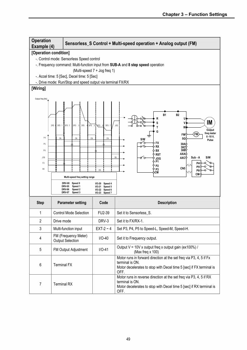
Chapter 3 – Function Settings
49
Operation Example (4)
Sensorless_S Control + Multi-speed operation + Analog output (FM)
[Operation condition]
-. Control mode: Sensorless Speed control
-. Frequency command: Multi-function input from SUB-A and 8 step speed operation
(Multi-speed 7 + Jog freq 1)
-. Accel time: 5 [Sec], Decel time: 5 [Sec]
-. Drive mode: Run/Stop and speed output via terminal FX/RX
[Wiring]
I/O-20 Speed 4I/O-21 Speed 5I/O-22 Speed 6I/O-23 Speed 7
Multi-speed freq setting range
DRV-00 Speed 0DRV-05 Speed 1DRV-06 Speed 2DRV-07 Speed 3
ON ON ON ON
ON
ON
ON
ON
ON
ON
SPD 0 SPD 1 SPD 2 SPD 3 SPD 4 SPD 5 SPD 6 SPD 7 JOG
P4
P5
P6
JOG
FX
RX
Output freq [Hz]
Outputfreq meter
0 -10 V,Pulse
R
S
T
G
U
V
W
B1 B2
FXRX
BX
RST
JOGP1
P2P3
CM
FM
5G
30C30B
AXA
AXC
IM
S/W
P4
CN5 P5P6
CM
Sub - A S/W
FM
30A
Step Parameter setting Code Description
1 Control Mode Selection FU2-39 Set it to Sensorless_S.
2 Drive mode DRV-3 Set it to FX/RX-1.
3 Multi-function input EXT-2 ~ 4 Set P3, P4, P5 to Speed-L, Speed-M, Speed-H.
4 FM (Frequency Meter) Output Selection
I/O-40 Set it to Frequency output.
5 FM Output Adjustment I/O-41 Output V = 10V x output freq x output gain (ex100%) / (Max freq x 100)
6 Terminal FX
Motor runs in forward direction at the set freq via P3, 4, 5 if Fx terminal is ON. Motor decelerates to stop with Decel time 5 [sec] if FX terminal is OFF.
7 Terminal RX
Motor runs in reverse direction at the set freq via P3, 4, 5 if RX terminal is ON. Motor decelerates to stop with Decel time 5 [sec] if RX terminal is OFF.

Chapter 3 – Function Setting
50
Operation Example (5)
Vector_SPD Control
[Operation condition]
-. Control Mode: Vector_SPD Control, -. Encoder specification: Pulse number (1024), Line Drive type
-. Freq command: set 55[Hz] via KPD-1
-. Accel/Decel time: Accel – 15 [sec], Decel – 25 [sec], -. Drive mode: Run/Stop via terminal FX/RX
[Wiring]
AOC
R
S
T
G
U
V
W
B1 B2
FXRXBXRSTJOGP1P2P3CM
VRV15G
IM
3PAC
Input
BOCA+
A-
B+
B-FBA
FBB
GND
EEncoder
GND
+5V+5V
VCCVCC
Keypadconnector
MODE PROG ENT
REV
SHIFTESC
STOPRESET
FWD
LC-200
Sub-B
Step Parameter setting Code Description
1 Motor related setting FU2-30 ~ FU2-36
Set motor capacity, pole number, rated voltage/ current/slip and efficiency.
2 Encoder related setting EXT-12 EXT-15 EXT-16
Set EXT-12 to Feed-back, EXT-1 to A+B. Set EXT-16 to 1024.
3 Control Mode Selection Fu2-39 Encoder related setting should be done before setting control mode to Vector_SPD.
4 Auto-tuning FU2-40 Auto-tuning starts when set to ALL. Read the encoder manual carefully to clear the error if the messages ” Enc Err”, “Enc Rev” are displayed.
5 Keypad input setting DRV-4 DRV-0
Set DRV-4 to KPD-1 and press the Prog key to set 55 [Hz] in Drv-0.
6 Accel/Decel time setting DRV-2 DRV-3
Accel time: set 15[Sec] Decel time: set 25[Sec]
7 Drive mode DRV-3 Set it to FX/RX-1.
8 FX/RX terminal
Motor runs with Accel time 15 [Sec] at 55 [Hz] if FX/RX terminal is turned ON. Motor decelerates to stop with Decel time 25 [Sec] if FX/RX terminal is turned OFF.

51
CHAPTER 4 - QUICK-START PROCEDURES
These Quick-Start Up instructions are for those applications where:
l The user wants to get the iS5 inverter started quickly.
l The factory-preset values are suitable for the user application.
The factory-preset values are shown on the ‘Chapter 5 - Parameter List’. The iS5 inverter is configured to operate a
motor at 60Hz (base frequency). If the application requires coordinated control with other controllers, it is
recommended the user become familiar with all parameters and features of the inverter before applying AC power.
1. Mounting the inverter (mount the inverter as described in ‘1.3 Mounting’)
l Install in a clean, dry location.
l Allow a sufficient clearance around top and sides of inverter.
l The ambient temperature should not exceed 40°C (104°F).
l If two or more inverters are installed in an enclosure, add additional cooling.
2. Wiring the inverter (connect wiring as described in ‘1.7 Power Terminals’)
l AC power should be turned OFF.
l Verify the AC power matches the nameplate voltage.
l Remove the screw on the bottom front cover of the inverter for terminal board access (For terminal board
access on 15~ 30HP inverters you must disconnect the keypad cable from the inverter and fully remove the
cover).

Chapter 4 – Quick start procedures
52
4.1 Operating using keypad
1. Apply AC power.
2. LCD: Press [▲] key three times.
7-Seg: Rotate the encoder knob until
‘03’ is displayed.
3. LCD: Press [PROG] key.
7-Seg: Press [PROG/ENT] key.
4. LCD: Press [▼] key one time.
7-Seg: Rotate the encoder knob left.
5. LCD: Press [PROG] key.
7-Seg: Press [PROG/ENT] key.
6. Press [PROG/ENT] key.
7. LCD: Press [PROG] key.
7-Seg: Press [PROG/ENT] key.
8. LCD: Press [SHIFT/ESC] key and
press [▲] key to increase the
command frequency.
7-Seg: Rotate the encoder knob right
to change the command frequency.
The changing digit moves by pressing
the [SHIFT/ESC] key.
9. LCD: Press [ENT] key to save the
data.
7-Seg: Press [PROG/ENT] key to
save the data.
10. LCD: Press [FWD] or [REV] key to
start motor.
7-Seg: Press [RUN] key to start
motor.
11. Press [STOP/RESET] key to stop
motor.
LCD Display
7-Segment Display
DRV►T/K 0.0 A
00 STP 0.00Hz
DRV► Cmd. freq 00 0.00Hz
DRV► Cmd. freq
00 60.00Hz
DRV►K/K 0.0 A
00 STP 60.00Hz
DRV► Drive mode
03 Fx/Rx-1
DRV► Drive mode 03 Fx/Rx-1
DRV► Drive mode
03 Keypad
DRV► Drive mode
03 Keypad
The PROG/ENT LED turned ON.
The PROG/ENT LED is turned ON.
The DRV LED is ON.
The DRV LED is turned ON.
DRV►K/K 0.0 A 00 STP 0.00Hz
The PROG/ENT LED is turned ON.
The PROG/ENT LED is turned ON.
The FWD or REV LED starts blinking. The RUN LED starts blinking. To change the motor running direction, change DRV 13 to ‘1’.
The STOP/RESET LED starts blinking. The STOP/RESET LED starts blinking.

Chapter 4 – Quick start procedures
53
4.2 Operation using Control Terminals
1. Install a potentiometer on terminals
V1, VR, 5G and connect wiring as
shown below.
2. Apply AC power.
3. Confirm that the DRV 03 is set at
‘Fx/Rx-1’.
4. LCD: Press [▲] key to move DRV 04.
7-Seg: Rotate encoder knob until ‘04’
is displayed.
5. LCD: Press [PROG] key.
7-Seg: Press [PROG/ENT] key.
6. LCD: Press [▲] key and set at ‘V1’.
7-Seg: Rotate encoder knob and set
at ‘2’.
7. LCD: Press [ENT] key.
7-Seg: Press [PROG/ENT] key.
8. Press [SHIFT/ESC] key.
9. Set the frequency by rotating the
potentiometer.
10. Close the FX or RX contact to run the
motor.
11. Open the FX or RX contact to stop the
motor.
LCD Display
7-Segment Display
DRV►T/K 0.0 A
00 STP 0.00Hz The DRV LED is ON.
DRV► Drive mode
03 Fx/Rx-1
DRV► Freq mode
04 Keypad-1
DRV► Freq mode 04 Keypad-1
DRV► Freq mode
04 V1
DRV► Freq mode 04 V1
DRV►T/V 0.0 A 00 STP 0.00Hz
DRV►T/V 0.0 A 00 STP 60.00Hz
The PROG/ENT LED is turned ON.
The PROG/ENT LED is turned ON.
The PROG/ENT LED is turned OFF.
The FWD or REV LED starts blinking. The RUN LED starts blinking.
The STOP/RESET LED starts blinking. The STOP/RESET LED starts blinking.
1 ㏀, 1/2 W
P1 P2
JOG CM
P3 FX RX NC
CM BX RST I
VR VI
FM 5G

Chapter 4 – Quick start procedures
54
4.3 Operation using Keypad and Control Terminals
4.3.1 Frequency set by External Source and Run/Stop by Keypad
1. Install a potentiometer on terminals V1, VR, 5G and connect wiring as shown below left.
When a ‘4 to 20mA’ current source is used as the frequency reference, use terminals I and 5G as shown below.
2. Apply AC power.
3. LCD: Press [▲] key to move DRV 03.
7-Seg: Rotate encoder knob until ‘03’ is
displayed.
4. LCD: Press [PROG] key.
7-Seg: Press [PROG/ENT] key.
5. LCD: Press [▲] key one time.
7-Seg: Rotate encoder knob and set at ‘0’.
6. LCD: Press [ENT] key.
7-Seg: Press [PROG/ENT] key.
7. Confirm that the DRV 04 is set at ‘V1’.
8. Press [SHIFT/ESC] key.
Set the frequency by rotating the
potentiometer.
9. LCD: Press [FWD] or [REV] key.
7-Seg: Press [RUN] key.
P1 P2
JOG CM
P3 FX RX NC
CM BX RST I
VR VI
FM 5G
4 to 20mA signal
1 ㏀, 1/2 W
P1 P2
JOG CM
P3 FX RX NC
CM BX RST I
VR VI
FM 5G
DRV 04 must be set at V1. DRV 04 must be set at I.
DRV►T/K 0.0 A 00 STP 0.00Hz
The DRV LED is ON.
DRV► Drive mode
03 Fx/Rx-1
DRV► Drive mode 03 Fx/Rx-1
The PROG/ENT LED is turned ON.
DRV► Drive mode 03 Keypad
The PROG/ENT LED is turned ON.
DRV► Drive mode 03 Keypad
The PROG/ENT LED is turned OFF.
DRV► Freq mode 04 V1
The PROG/ENT LED is turned ON.
DRV►T/V 0.0 A
00 STP 60.00Hz
The FWD or REV LED starts blinking. The RUN LED starts blinking. To change the motor running direction, change DRV 13 to ‘1’.
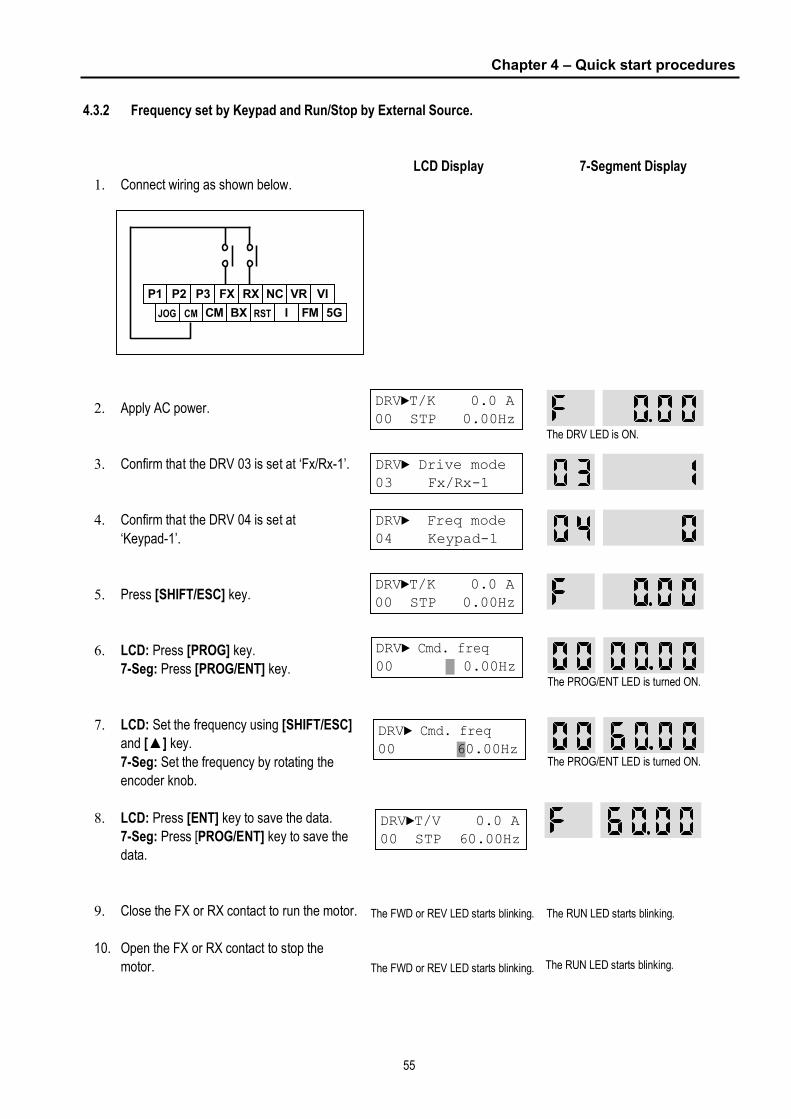
Chapter 4 – Quick start procedures
55
4.3.2 Frequency set by Keypad and Run/Stop by External Source.
1. Connect wiring as shown below.
2. Apply AC power.
3. Confirm that the DRV 03 is set at ‘Fx/Rx-1’.
4. Confirm that the DRV 04 is set at
‘Keypad-1’.
5. Press [SHIFT/ESC] key.
6. LCD: Press [PROG] key.
7-Seg: Press [PROG/ENT] key.
7. LCD: Set the frequency using [SHIFT/ESC]
and [▲] key.
7-Seg: Set the frequency by rotating the
encoder knob.
8. LCD: Press [ENT] key to save the data.
7-Seg: Press [PROG/ENT] key to save the
data.
9. Close the FX or RX contact to run the motor.
10. Open the FX or RX contact to stop the
motor.
LCD Display
7-Segment Display
P1 P2
JOG CM
P3 FX RX NC
CM BX RST I
VR VI
FM 5G
DRV►T/K 0.0 A 00 STP 0.00Hz
DRV► Drive mode 03 Fx/Rx-1
DRV► Freq mode 04 Keypad-1
DRV►T/K 0.0 A 00 STP 0.00Hz
DRV► Cmd. freq 00 0.00Hz
DRV►T/V 0.0 A 00 STP 60.00Hz
The FWD or REV LED starts blinking.
DRV► Cmd. freq 00 60.00Hz
The FWD or REV LED starts blinking.
The DRV LED is ON.
The PROG/ENT LED is turned ON.
The PROG/ENT LED is turned ON.
The RUN LED starts blinking.
The RUN LED starts blinking.

56
CHAPTER 5 - PARAMETER LIST
5.1 Drive Group [DRV]
Keypad Display Setting Range Code Description
LCD 7-Segment LCD 7-Segment Units
Factory Default
Adj. During
Run Page
DRV-0011
Command Frequency or
Command Torque
(Output Frequency/
Torque during motor run,
Reference Frequency/
Torque during motor
stop)
Output Current (LCD)
Cmd. freq
or
Cmd. Trq
F or r
(DRV-13) 0 to FU1-20 (Max. freq) 0.01 0.00 [Hz] Yes 79
DRV-01 Acceleration Time Acc. time 01 0 to 6000 0.1 20.0 [sec] Yes 80
DRV-02 Deceleration Time Dec. time 02 0 to 6000 0.1 30.0 [sec] Yes 81
Keypad 0
Fx/Rx-1 1 DRV-03 Drive Mode
(Run/Stop Method) Drive mode 03
Fx/Rx-2 2
- Fx/Rx-1 No 81
Keypad-1 0
Keypad-2 1
V1 2
I 3
DRV-04
Frequency Mode or
Torque Mode
(Frequency/Torque
setting Method)
Freq mode
or
Torque mode
04
V1+I 4
- Keypad-1 No 82
DRV-05 Step Frequency 1 Step freq-1 05 10.00 [Hz]
DRV-06 Step Frequency 2 Step freq-2 06 20.00 [Hz]
DRV-07 Step Frequency 3 Step freq-3 07
0 to FU1-20
(0 to Max. freq) 0.01
30.00 [Hz]
Yes 83
DRV-08 Output Current Current 08 Load Current in RMS - [A] - 84
DRV-09 Motor Speed Speed 09 Motor Speed in rpm - [rpm] - 84
DRV-10 DC link Voltage DC link Vtg 10 DC Link Voltage inside inverter - [V] - 84
DRV-11 User Display Selection User disp 11 Selected in FU2-73 (User Disp) - - - 84
DRV-12 Fault Display Fault 12 - - - None
nOn - 84
0 [Forward] DRV-13 Motor Direction Set
Not displayed in
LCD keypad 13 Not available
1 [reverse] - 0 Yes 85
DRV-14 Target/Output Frequency
Display Tar/Out Freq. 14 - - - 0.00 [Hz] Yes 85
DRV-1512 Reference/Feedback
Frequency Display Ref/Fbk Freq. 15 - - - 0.00 [Hz] Yes 85
Hz disp 0 DRV-16 Speed Unit Selection Hz/Rpm Disp 16
Rpm disp 1 - - Yes 85
DRV-20 FU1 Group Selection 20 85
DRV-21 FU2 Group Selection 21 85
DRV-22 I/O Group Selection 22 85
DRV-2313 EXT Group Selection
Not displayed in
LCD keypad
23
Not available Press
[PROG/ENT]
key - 1 Yes
85
11 The speed unit is changed to [%] when FU2-39 is set to ‘Sensorless_T’ or ‘Vector_TRQ’. 12 Code DRV-15 appears only when FU2-47 is set to ‘Yes’. 13 Code DRV-23 through DRV-24 appears only when a Sub-Board or an Option Board is installed.

Chapter 5 - Parameter List
57
Keypad Display Setting Range Code Description
LCD 7-Segment LCD 7-Segment Units
Factory Default
Adj. During
Run Page
DRV-24 COM Group Selection 24 - 1 Yes 85
DRV-25 APP Group Selection 25 - 1 Yes 85
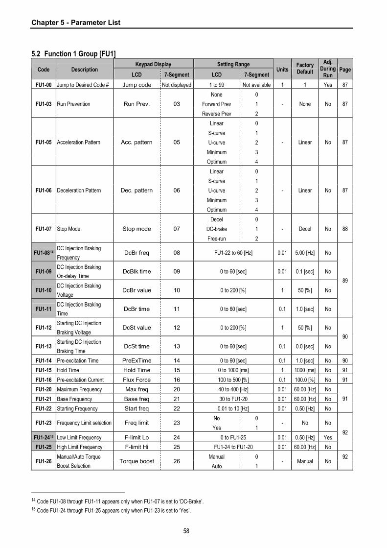
Chapter 5 - Parameter List
58
5.2 Function 1 Group [FU1]
Keypad Display Setting Range Code Description
LCD 7-Segment LCD 7-Segment Units
Factory Default
Adj. During
Run Page
FU1-00 Jump to Desired Code # Jump code Not displayed 1 to 99 Not available 1 1 Yes 87
None 0
Forward Prev 1 FU1-03 Run Prevention Run Prev. 03
Reverse Prev 2
- None No 87
Linear 0
S-curve 1
U-curve 2
Minimum 3
FU1-05 Acceleration Pattern Acc. pattern 05
Optimum 4
- Linear No 87
Linear 0
S-curve 1
U-curve 2
Minimum 3
FU1-06 Deceleration Pattern Dec. pattern 06
Optimum 4
- Linear No 87
Decel 0
DC-brake 1 FU1-07 Stop Mode Stop mode 07
Free-run 2
- Decel No 88
FU1-0814 DC Injection Braking
Frequency DcBr freq 08 FU1-22 to 60 [Hz] 0.01 5.00 [Hz] No
FU1-09 DC Injection Braking
On-delay Time DcBlk time 09 0 to 60 [sec] 0.01 0.1 [sec] No
FU1-10 DC Injection Braking
Voltage DcBr value 10 0 to 200 [%] 1 50 [%] No
FU1-11 DC Injection Braking
Time DcBr time 11 0 to 60 [sec] 0.1 1.0 [sec] No
89
FU1-12 Starting DC Injection
Braking Voltage DcSt value 12 0 to 200 [%] 1 50 [%] No
FU1-13 Starting DC Injection
Braking Time DcSt time 13 0 to 60 [sec] 0.1 0.0 [sec] No
90
FU1-14 Pre-excitation Time PreExTime 14 0 to 60 [sec] 0.1 1.0 [sec] No 90
FU1-15 Hold Time Hold Time 15 0 to 1000 [ms] 1 1000 [ms] No 91
FU1-16 Pre-excitation Current Flux Force 16 100 to 500 [%] 0.1 100.0 [%] No 91
FU1-20 Maximum Frequency Max freq 20 40 to 400 [Hz] 0.01 60.00 [Hz] No
FU1-21 Base Frequency Base freq 21 30 to FU1-20 0.01 60.00 [Hz] No
FU1-22 Starting Frequency Start freq 22 0.01 to 10 [Hz] 0.01 0.50 [Hz] No
91
No 0 FU1-23 Frequency Limit selection Freq limit 23
Yes 1 - No No
FU1-2415 Low Limit Frequency F-limit Lo 24 0 to FU1-25 0.01 0.50 [Hz] Yes
FU1-25 High Limit Frequency F-limit Hi 25 FU1-24 to FU1-20 0.01 60.00 [Hz] No
92
Manual 0 FU1-26
Manual/Auto Torque
Boost Selection Torque boost 26
Auto 1 - Manual No
92
14 Code FU1-08 through FU1-11 appears only when FU1-07 is set to ‘DC-Brake’. 15 Code FU1-24 through FU1-25 appears only when FU1-23 is set to ‘Yes’.
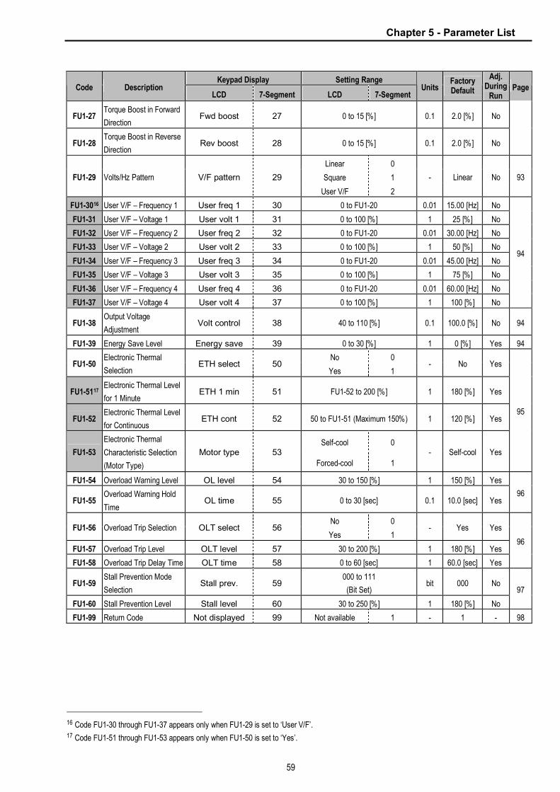
Chapter 5 - Parameter List
59
Keypad Display Setting Range Code Description
LCD 7-Segment LCD 7-Segment Units
Factory Default
Adj. During
Run Page
FU1-27 Torque Boost in Forward
Direction Fwd boost 27 0 to 15 [%] 0.1 2.0 [%] No
FU1-28 Torque Boost in Reverse
Direction Rev boost 28 0 to 15 [%] 0.1 2.0 [%] No
Linear 0
Square 1 FU1-29 Volts/Hz Pattern V/F pattern 29
User V/F 2
- Linear No 93
FU1-3016 User V/F – Frequency 1 User freq 1 30 0 to FU1-20 0.01 15.00 [Hz] No
FU1-31 User V/F – Voltage 1 User volt 1 31 0 to 100 [%] 1 25 [%] No
FU1-32 User V/F – Frequency 2 User freq 2 32 0 to FU1-20 0.01 30.00 [Hz] No
FU1-33 User V/F – Voltage 2 User volt 2 33 0 to 100 [%] 1 50 [%] No
FU1-34 User V/F – Frequency 3 User freq 3 34 0 to FU1-20 0.01 45.00 [Hz] No
FU1-35 User V/F – Voltage 3 User volt 3 35 0 to 100 [%] 1 75 [%] No
FU1-36 User V/F – Frequency 4 User freq 4 36 0 to FU1-20 0.01 60.00 [Hz] No
FU1-37 User V/F – Voltage 4 User volt 4 37 0 to 100 [%] 1 100 [%] No
94
FU1-38 Output Voltage
Adjustment Volt control 38 40 to 110 [%] 0.1 100.0 [%] No 94
FU1-39 Energy Save Level Energy save 39 0 to 30 [%] 1 0 [%] Yes 94
No 0 FU1-50
Electronic Thermal
Selection ETH select 50
Yes 1 - No Yes
FU1-5117 Electronic Thermal Level
for 1 Minute ETH 1 min 51 FU1-52 to 200 [%] 1 180 [%] Yes
FU1-52 Electronic Thermal Level
for Continuous ETH cont 52 50 to FU1-51 (Maximum 150%) 1 120 [%] Yes
Self-cool 0 FU1-53
Electronic Thermal
Characteristic Selection
(Motor Type)
Motor type 53
Forced-cool 1
- Self-cool Yes
95
FU1-54 Overload Warning Level OL level 54 30 to 150 [%] 1 150 [%] Yes
FU1-55 Overload Warning Hold
Time OL time 55 0 to 30 [sec] 0.1 10.0 [sec] Yes
96
No 0 FU1-56 Overload Trip Selection OLT select 56
Yes 1 - Yes Yes
FU1-57 Overload Trip Level OLT level 57 30 to 200 [%] 1 180 [%] Yes
FU1-58 Overload Trip Delay Time OLT time 58 0 to 60 [sec] 1 60.0 [sec] Yes
96
FU1-59 Stall Prevention Mode
Selection Stall prev. 59
000 to 111
(Bit Set) bit 000 No
FU1-60 Stall Prevention Level Stall level 60 30 to 250 [%] 1 180 [%] No
97
FU1-99 Return Code Not displayed 99 Not available 1 - 1 - 98
16 Code FU1-30 through FU1-37 appears only when FU1-29 is set to ‘User V/F’. 17 Code FU1-51 through FU1-53 appears only when FU1-50 is set to ‘Yes’.
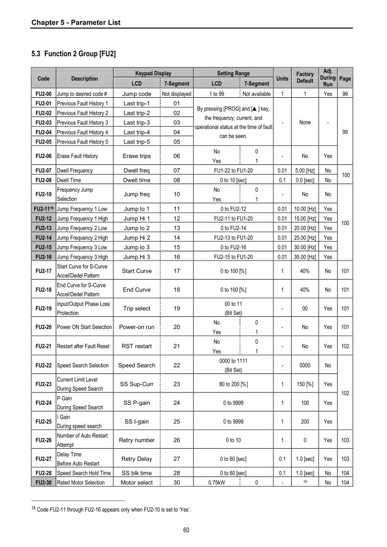
Chapter 5 - Parameter List
60
5.3 Function 2 Group [FU2]
Keypad Display Setting Range Code Description
LCD 7-Segment LCD 7-Segment Units
Factory Default
Adj. During
Run Page
FU2-00 Jump to desired code # Jump code Not displayed 1 to 99 Not available 1 1 Yes 99
FU2-01 Previous Fault History 1 Last trip-1 01
FU2-02 Previous Fault History 2 Last trip-2 02
FU2-03 Previous Fault History 3 Last trip-3 03
FU2-04 Previous Fault History 4 Last trip-4 04
FU2-05 Previous Fault History 5 Last trip-5 05
By pressing [PROG] and [▲] key,
the frequency, current, and
operational status at the time of fault
can be seen.
- None -
No 0 FU2-06 Erase Fault History Erase trips 06
Yes 1 - No Yes
99
FU2-07 Dwell Frequency Dwell freq 07 FU1-22 to FU1-20 0.01 5.00 [Hz] No
FU2-08 Dwell Time Dwell time 08 0 to 10 [sec] 0.1 0.0 [sec] No 100
No 0 FU2-10
Frequency Jump
Selection Jump freq 10
Yes 1 - No No
FU2-1118 Jump Frequency 1 Low Jump lo 1 11 0 to FU2-12 0.01 10.00 [Hz] Yes
FU2-12 Jump Frequency 1 High Jump Hi 1 12 FU2-11 to FU1-20 0.01 15.00 [Hz] Yes
FU2-13 Jump Frequency 2 Low Jump lo 2 13 0 to FU2-14 0.01 20.00 [Hz] Yes
FU2-14 Jump Frequency 2 High Jump Hi 2 14 FU2-13 to FU1-20 0.01 25.00 [Hz] Yes
FU2-15 Jump Frequency 3 Low Jump lo 3 15 0 to FU2-16 0.01 30.00 [Hz] Yes
FU2-16 Jump Frequency 3 High Jump Hi 3 16 FU2-15 to FU1-20 0.01 35.00 [Hz] Yes
100
FU2-17 Start Curve for S-Curve
Accel/Dedel Pattern Start Curve 17 0 to 100 [%] 1 40% No 101
FU2-18 End Curve for S-Curve
Accel/Dedel Pattern End Curve 18 0 to 100 [%] 1 40% No 101
FU2-19 Input/Output Phase Loss
Protection Trip select 19
00 to 11
(Bit Set) - 00 Yes 101
No 0 FU2-20 Power ON Start Selection Power-on run 20
Yes 1 - No Yes 101
No 0 FU2-21 Restart after Fault Reset RST restart 21
Yes 1 - No Yes 102
FU2-22 Speed Search Selection Speed Search 22 0000 to 1111
(Bit Set) - 0000 No
FU2-23 Current Limit Level
During Speed Search SS Sup-Curr 23 80 to 200 [%] 1 150 [%] Yes
FU2-24 P Gain
During Speed Search SS P-gain 24 0 to 9999 1 100 Yes
FU2-25 I Gain
During speed search SS I-gain 25 0 to 9999 1 200 Yes
102
FU2-26 Number of Auto Restart
Attempt Retry number 26 0 to 10 1 0 Yes 103
FU2-27 Delay Time
Before Auto Restart Retry Delay 27 0 to 60 [sec] 0.1 1.0 [sec] Yes 103
FU2-28 Speed Search Hold Time SS blk time 28 0 to 60 [sec] 0.1 1.0 [sec] No 104
FU2-30 Rated Motor Selection Motor select 30 0.75kW 0 - 19 No 104
18 Code FU2-11 through FU2-16 appears only when FU2-10 is set to ‘Yes’.

Chapter 5 - Parameter List
61
Keypad Display Setting Range Code Description
LCD 7-Segment LCD 7-Segment Units
Factory Default
Adj. During
Run Page
1.5kW 1
2.2kW 2
3.7kW 3
5.5kW 4
7.5kW 5
11.0kW 6
15.0kW 7
18.5kW 8
22.0kW 9
30.0 kW 10
37.0 kW 11
45.0 kW 12
55.0 kW 13
75.0 kW 14
FU2-31 Number of Motor Poles Pole number 31 2 to 12 1 4 No 104
FU2-32 Rated Motor Slip Rated-Slip 32 0 t o10 [Hz] 0.01 No 104
FU2-33 Rated Motor Current
(RMS) Rated-Curr 33 1 to 200 [A] 1 No 104
FU2-34 No Load Motor Current
(RMS) Noload-Curr 34 0.5 to 200 [A] 1 No 104
FU2-35 Motor Rated Voltage Motor Volt 35 180..460 [V] No 104
FU2-36 Motor Efficiency Efficiency 36 70 to 100 [%] 1
20
No 104
FU2-37 Load Inertia Inertia rate 37 0 to 1 1 0 No 104
FU2-38 Carrier Frequency Carrier freq 38 1 to 15 [kHz] 1 5 [kHz] Yes 106
V/F 0
Slip comp 1
Sensorless_S 2
Sensorless_T 3
Vector_SPD 4
FU2-39 Control Mode Selection Control mode 40
Vector_TRQ 5
- V/F No 106
No 0
All 1
Rs + Lsigma 2
Enc Test 3
FU2-40 Auto Tuning Auto tuning 41
Tr 4
- No No
FU2-4121 Stator Resistance of
Motor Rs 42 0 to (depend on FU2-30) [ohm] 0.001 No
FU2-42 Leakage Inductance of
Motor Lsigma 44 0 to (depend on FU2-30) [mH] 0.001 No
FU2-43 Stator Inductance of
Motor Ls 43 0 to (depend on FU2-30) [mH]
22
No
108
19 The rated motor is automatically set according to the inverter model name. If different, set the motor capacity connected. 20 This value is automatically entered according to the rated motor set in FU2-30. If different, set the correct value of the motor. 21 Code FU2-41 through FU2-46 appears only when FU2-39 is set to ‘Sensorless_X’ or ‘Vector_XXX’. 22 This value is automatically entered according to the rated motor set in FU2-30. If different, set the correct value of the motor.

Chapter 5 - Parameter List
62
Keypad Display Setting Range Code Description
LCD 7-Segment LCD 7-Segment Units
Factory Default
Adj. During
Run Page
FU2-44 Rotor Time Constant Tr 44 0 to (depend on FU2-30) [mS] No
FU2-45 P Gain for Sensorless
Control SL P-gain 45 0 to 32767 1 1000 Yes 109
FU2-46 I Gain for Sensorless
Control SL I-gain 46 0 to 32767 1 100 Yes 109
No 0 FU2-47 PID Operation Selection Proc PI mode 47
Yes 1 - No No 110
FU2-4823 PID F Gain PID F-gain 48 0 to 999.9 [%] 0.1 0 [%] Yes
None 0
Keypad-1 1
Keypad-2 2
V1 3
I 4
FU2-49 PID Auxiliary Reference
Mode Selection Aux Ref Mode 49
V2 5
- None No
FU2-50 PID Output Direction
Selection PID Out Dir 50 Target freq. 0 - Target freq. No
110
I 0
V1 1 FU2-51 PID Feedback Signal
Selection PID F/B 51
V2 2
- I No
FU2-52 P Gain for PID Control PID P-gain 52 0 to 999.9 [%] 0.1 1.0 [%] Yes
FU2-53 I Gain for PID Control PID I-time 53 0 to 32.0 [sec] 0.1 10.0 [sec] Yes
FU2-54 D Gain for PID Control PID D-time 54 0 to 1000 [msec] 0.1 0.0 [msec] Yes
FU2-55 High Limit Frequency for
PID Control PID limit-H 55 0 to 300.00 [Hz] 0.01 60.00 [Hz] Yes
FU2-56 Low Limit Frequency for
PID Control PID limit-L 56 0 to 300.00 [Hz] 0.01 0.00 [Hz] Yes
110
No 0 FU2-57 PID Output Inversion PID Out Inv. 57
Yes 1 - No No
FU2-58 PID Output Scale PID Out Scale 58 0.1 to 999.9 [%] 0.1 100 [%] No
FU2-59 PID P2 Gain PID P2-gain 59 0 to 999.9 [%] 0.1 100 [%] No
FU2-60 P Gain Scale P-gain Scale 60 0 to 100 [%] 0.1 100 [%] No
111
FU2-69 Accel/Decel Change
Frequency Acc/Dec ch F 69 0 to FU1-20 0.00 [Hz] No 114
Max freq 0 FU2-70
Reference Frequency for
Accel and Decel Acc/Dec freq 70
Delta freq 1 - Max freq No 114
0.01 [sec] 0
0.1 [sec] 1 FU2-71 Accel/Decel Time Scale Time scale 71
1 [sec] 2
0.01 0.1 [sec] Yes 114
FU2-72 Power On Display PowerOn disp 72 0 to 12 1 0 Yes 114
Voltage 0 FU2-73 User Display Selection User disp 73
Watt 1 - Voltage Yes 115
FU2-74 Gain for Motor Speed
Display RPM factor 74 1 to 1000 [%] 1 100 [%] Yes 115
23 Code FU2-48 through FU2-62 appears only when FU2-47 is set to ‘Yes’.

Chapter 5 - Parameter List
63
Keypad Display Setting Range Code Description
LCD 7-Segment LCD 7-Segment Units
Factory Default
Adj. During
Run Page
None 0
Int. DB-R 1 FU2-75 DB (Dynamic Braking)
Resistor Mode Selection DB mode 75
Ext. DB-R 2
- Int. DB-R Yes 115
FU2-7624 Duty of Dynamic Braking
Resistor DB %ED 76 0 to 30 [%] 1 10 [%] Yes 115
FU2-79 Software Version S/W version 79 Ver x.xx - - - 116
FU2-8125 2nd Acceleration Time 2nd Acc time 81 0 to 6000 [sec] 0.1 5.0 [sec] Yes
FU2-82 2nd Deceleration Time 2nd Dec time 82 0 to 6000 [sec] 0.1 10.0 [sec] Yes
FU2-83 2nd Base Frequency 2nd BaseFreq 83 30 to FU1-20 0.01 60.00 [Hz] No
Linear 0
Square 1 FU2-84 2nd V/F Pattern 2nd V/F 84
User V/F 2
- Linear No
FU2-85 2nd Forward Torque Boost 2nd F-boost 85 0 to 15 [%] 0.1 2.0 [%] No
FU2-86 2nd Reverse Torque
Boost 2nd R-boost 86 0 to 15 [%] 0.1 2.0 [%] No
FU2-87 2nd Stall Prevention Level 2nd Stall 87 30 to 150 [%] 1 150[%] No
FU2-88 2nd Electronic Thermal
Level for 1 minute 2nd ETH 1min 88 FU2-89 to 200 [%] 1 150 [%] Yes
FU2-89 2nd Electronic Thermal
Level for continuous 2nd ETH cont 89
50 to FU2-88
(Maximum 150%) 1 100 [%] Yes
FU2-90 2nd Rated Motor Current 2nd R-Curr 90 1 to 200 [A] 0.1 3.6 [A] No
116
No 0 FU2-91
Read Parameters into
Keypad from Inverter Para. Read 91
Yes 1 - No No
No 0 FU2-92
Write Parameters to
Inverter from Keypad Para. Write 92
Yes 1 - No No
116
No 0
All Groups 1
DRV 2
FU1 3
FU2 4
I/O 5
FU2-93 Initialize Parameters Para. Init 93
EXT 6
- No No 117
FU2-94 Parameter Write
Protection Para. Lock 94 0 to 255 1 0 Yes 117
FU2-99 Return Code Not displayed 99 Not available
[PROG/ENT]
or
[SHIFT/ESC]
- 1 Yes 117
☞ Note: FU2-41, 42, 43, 44, 45, 46 not displayed when FU2-39 is set to V/f or Slip compen.
24 Code FU2-76 appears only when FU2-75 is set to ‘Ext. DB-R’. 25 Code FU2-81 through FU2-90 appear only when one of I/O-12 ~ I/O-14 is set to ‘2nd function’.

Chapter 5 - Parameter List
64
5.4 Input/Output Group [I/O]
Keypad Display Setting Range Code Description
LCD 7-Segment LCD 7-Segment Units
Factory Default
Adj. During
Run Page
I/O-00 Jump to Desired Code # Jump code Not displayed 1 to 99 Not available 1 1 Yes 118
I/O-01 Filtering Time Constant
for V1 Signal Input V1 filter 01 0 to 9999 [ms] 1 10 [ms] Yes
I/O-02 V1 Input Minimum
Voltage V1 volt x1 02 0 to 10 [V] 0.01 0.00 [V] Yes
I/O-03
Frequency
Corresponding to V1
Input Minimum Voltage
V1 freq y1/
V1 [%] y1 03
0 to FU1-20 [Hz]/
0-150 [%] 0.01
0.0 [Hz]/
0[%] Yes
I/O-04 V1 Input Maximum
Voltage V1 volt x2 04 0 to 10 [V] 0.01 10.00 [V] Yes
I/O-05
Frequency
Corresponding to V1
Input Maximum Voltage
V1 freq y2/
V1 [%] y2 05
0 to FU1-20/
0-150 [%] 0.01
60.00 [Hz]/
100[%] Yes
118
I/O-06 Filtering Time Constant
for I Signal Input I filter 06 0 to 9999 [ms] 1 10 [ms] Yes
I/O-07 I Input Minimum Current I curr x1 07 0 to 20 [mA] 0.01 4.00 [mA] Yes
I/O-08
Frequency
Corresponding to I Input
Minimum Current
I freq y1/
I [%] y1 08
0 to FU1-20
0-150 [%] 0.01
0.0 [Hz]/
0[%] Yes
118
I/O-09 I Input Maximum Current I curr x2 09 0 to 20 [mA] 0.01 20.00 [mA] Yes
I/O-10
Frequency
Corresponding to I Input
Maximum Current
I freq y2/
I [%] y2 10
0 to FU1-20/
0-150 [%] 0.01
60.00 [Hz]/
100[%] Yes
118
None 0
half of x1 1 I/O-11 Criteria for Analog Input
Signal Loss Wire broken 11
below x1 2
- None Yes 119
Speed-L 0
Speed-M 1
Speed-H 2
XCEL-L 3
XCEL-M 4
XCEL-H 5
Dc-brake 6
2nd Func 7
Exchange 8
- Reserved - 9
Up 10
Down 11
3-Wire 12
Ext Trip-A 13
Ext Trip-B 14
iTerm Clear 15
Open-loop 16
I/O-12 Multi-Function Input
Terminal ‘P1’ Define
P1 define 12
Main-drive 17
- Speed-L Yes 120

Chapter 5 - Parameter List
65
Keypad Display Setting Range Code Description
LCD 7-Segment LCD 7-Segment Units
Factory Default
Adj. During
Run Page
Analog hold 18
XCEL stop 19
P Gain2 20
SEQ-L 21
SEQ-M 22
SEQ-H 23
Manual 24
Go step 25
Hold step 26
Trv Off.Lo 27
Trv Off.Hi 28
Interlock1 29
Interlock2 30
Interlock3 31
Interlock4 32
Speed-X 33
Reset 34
BX 35
JOG 36
FX 37
RX 38
Ana Change 39
Pre excite 40
Spd/Trq 41
ASR P/PI 42
I/O-13 Multi-function Input
Terminal ‘P2’ Define P2 define 13 - Speed-M Yes
I/O-14 Multi-function Input
Terminal ‘P3’ Define P3 define 14
Same as Above
- Speed-H Yes
120
I/O-15 Terminal Input Status In status 15 000000000 to 111111111 - - -
I/O-16 Terminal Output Status Out status 16 0000 to 1111 - - - 126
I/O-17
Filtering Time Constant
for Multi-Function Input
Terminals
Ti Filt Num 17 2 to 50 1 15 Yes 126
I/O-20 Jog Frequency Setting Jog freq 20 10.00 [Hz] Yes 126
I/O-21 Step Frequency 4 Step freq-4 21 40.00 [Hz] Yes
I/O-22 Step Frequency 5 Step freq-5 22 50.00 [Hz] Yes
I/O-23 Step Frequency 6 Step freq-6 23 40.00 [Hz] Yes
I/O-24 Step Frequency 7 Step freq-7 24
0 to FU1-20 0.01
30.00 [Hz] Yes
126
I/O-25 Acceleration Time 1
for Step Frequency Acc time-1 25 0 to 6000 [sec] 0.1 20.0 [sec] Yes
I/O-26 Deceleration Time 1
for Step Frequency Dec time-1 26 0 to 6000 [sec] 0.1 20.0 [sec] Yes
I/O-27 Acceleration Time 2 Acc time-2 27 0 to 6000 [sec] 0.1 30.0 [sec] Yes
I/O-28 Deceleration Time 2 Dec time-2 28 0 to 6000 [sec] 0.1 30.0 [sec] Yes
I/O-29 Acceleration Time 3 Acc time-3 29 0 to 6000 [sec] 0.1 40.0 [sec] Yes
127

Chapter 5 - Parameter List
66
Keypad Display Setting Range Code Description
LCD 7-Segment LCD 7-Segment Units
Factory Default
Adj. During
Run Page
I/O-30 Deceleration Time 3 Dec time-3 30 0 to 6000 [sec] 0.1 40.0 [sec] Yes
I/O-31 Acceleration Time 4 Acc time-4 31 0 to 6000 [sec] 0.1 50.0 [sec] Yes
I/O-32 Deceleration Time 4 Dec time-4 32 0 to 6000 [sec] 0.1 50.0 [sec] Yes
I/O-33 Acceleration Time 5 Acc time-5 33 0 to 6000 [sec] 0.1 40.0 [sec] Yes
I/O-34 Deceleration Time 5 Dec time-5 34 0 to 6000 [sec] 0.1 40.0 [sec] Yes
I/O-35 Acceleration Time 6 Acc time-6 35 0 to 6000 [sec] 0.1 30.0 [sec] Yes
I/O-36 Deceleration Time 6 Dec time-6 36 0 to 6000 [sec] 0.1 30.0 [sec] Yes
I/O-37 Acceleration Time 7 Acc time-7 37 0 to 6000 [sec] 0.1 20.0 [sec] Yes
I/O-38 Deceleration Time 7 Dec time-7 38 0 to 6000 [sec] 0.1 20.0 [sec] Yes
Frequency 0
Current 1
Voltage 2
DC link Vtg 3
I/O-40 FM (Frequency Meter)
Output Selection FM mode 40
Torque 4
- Frequency Yes
I/O-41 FM Output Adjustment FM adjust 41 10 to 200 [%] 1 100 [%] Yes
128
I/O-42 Frequency Detection
Level FDT freq 42 0 to FU1-20 0.01 30.00 [Hz] Yes
I/O-43 Frequency Detection
Bandwidth FDT band 43 0 to FU1-20 0.01 10.00 [Hz] Yes
128
FDT-1 0
FDT-2 1
FDT-3 2
FDT-4 3
FDT-5 4
OL 5
IOL 6
Stall 7
OV 8
LV 9
OH 10
Lost Command 11
Run 12
Stop 13
Steady 14
INV line 15
COMM line 16
Ssearch 17
Step pulse 18
Seq pulse 19
Ready 20
Trv. ACC 21
Trv. DEC 22
MMC 23
Zspd Dect 24
I/O-44
Multi-Function Auxiliary
Contact Output Define
(AXA, AXC)
Aux mode 44
Torq Dect 25
- Run Yes 129
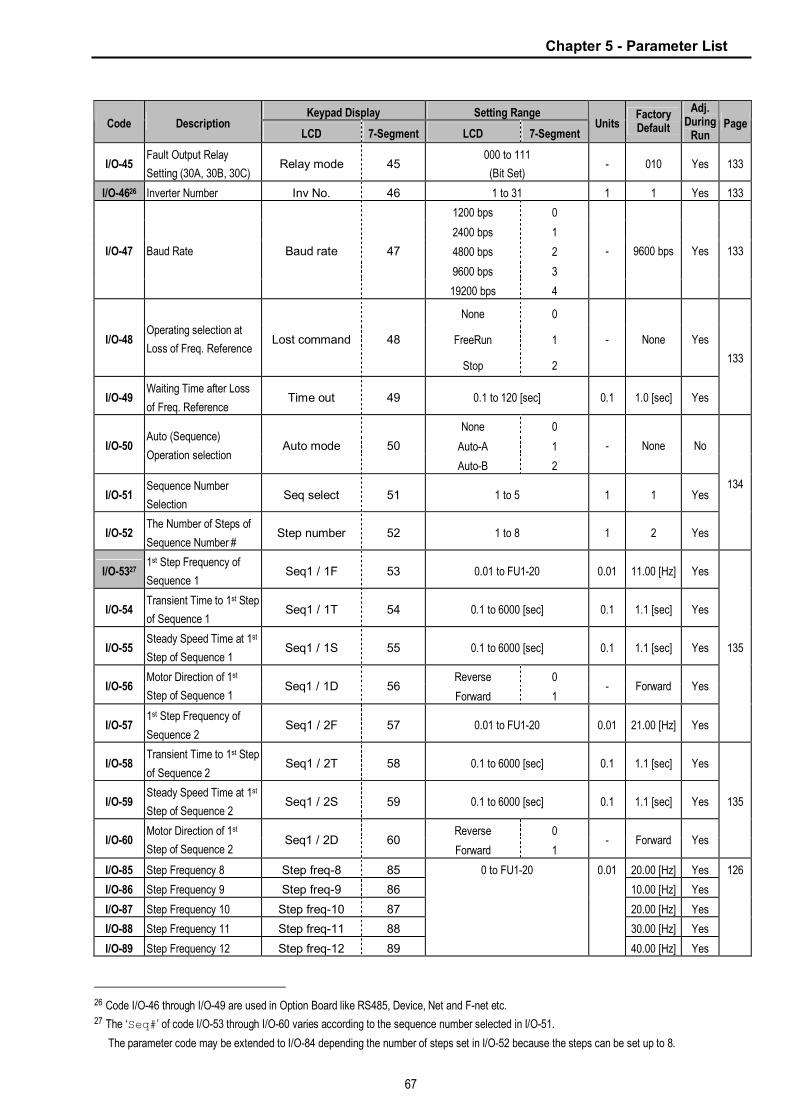
Chapter 5 - Parameter List
67
Keypad Display Setting Range Code Description
LCD 7-Segment LCD 7-Segment Units
Factory Default
Adj. During
Run Page
I/O-45 Fault Output Relay
Setting (30A, 30B, 30C) Relay mode 45
000 to 111
(Bit Set) - 010 Yes 133
I/O-4626 Inverter Number Inv No. 46 1 to 31 1 1 Yes 133
1200 bps 0
2400 bps 1
4800 bps 2
9600 bps 3
I/O-47 Baud Rate Baud rate 47
19200 bps 4
- 9600 bps Yes 133
None 0
FreeRun 1 I/O-48 Operating selection at
Loss of Freq. Reference Lost command 48
Stop 2
- None Yes
I/O-49 Waiting Time after Loss
of Freq. Reference Time out 49 0.1 to 120 [sec] 0.1 1.0 [sec] Yes
133
None 0
Auto-A 1 I/O-50 Auto (Sequence)
Operation selection Auto mode 50
Auto-B 2
- None No
I/O-51 Sequence Number
Selection Seq select 51 1 to 5 1 1 Yes
I/O-52 The Number of Steps of
Sequence Number # Step number 52 1 to 8 1 2 Yes
134
I/O-5327 1st Step Frequency of
Sequence 1 Seq1 / 1F 53 0.01 to FU1-20 0.01 11.00 [Hz] Yes
I/O-54 Transient Time to 1st Step
of Sequence 1 Seq1 / 1T 54 0.1 to 6000 [sec] 0.1 1.1 [sec] Yes
I/O-55 Steady Speed Time at 1st
Step of Sequence 1 Seq1 / 1S 55 0.1 to 6000 [sec] 0.1 1.1 [sec] Yes
Reverse 0 I/O-56
Motor Direction of 1st
Step of Sequence 1 Seq1 / 1D 56
Forward 1 - Forward Yes
I/O-57 1st Step Frequency of
Sequence 2 Seq1 / 2F 57 0.01 to FU1-20 0.01 21.00 [Hz] Yes
135
I/O-58 Transient Time to 1st Step
of Sequence 2 Seq1 / 2T 58 0.1 to 6000 [sec] 0.1 1.1 [sec] Yes
I/O-59 Steady Speed Time at 1st
Step of Sequence 2 Seq1 / 2S 59 0.1 to 6000 [sec] 0.1 1.1 [sec] Yes
Reverse 0 I/O-60
Motor Direction of 1st
Step of Sequence 2 Seq1 / 2D 60
Forward 1 - Forward Yes
135
I/O-85 Step Frequency 8 Step freq-8 85 20.00 [Hz] Yes
I/O-86 Step Frequency 9 Step freq-9 86 10.00 [Hz] Yes
I/O-87 Step Frequency 10 Step freq-10 87 20.00 [Hz] Yes
I/O-88 Step Frequency 11 Step freq-11 88 30.00 [Hz] Yes
I/O-89 Step Frequency 12 Step freq-12 89
0 to FU1-20 0.01
40.00 [Hz] Yes
126
26 Code I/O-46 through I/O-49 are used in Option Board like RS485, Device, Net and F-net etc. 27 The ‘Seq#’ of code I/O-53 through I/O-60 varies according to the sequence number selected in I/O-51.
The parameter code may be extended to I/O-84 depending the number of steps set in I/O-52 because the steps can be set up to 8.

Chapter 5 - Parameter List
68
Keypad Display Setting Range Code Description
LCD 7-Segment LCD 7-Segment Units
Factory Default
Adj. During
Run Page
I/O-90 Step Frequency 13 Step freq-13 90 50.00 [Hz] Yes
I/O-91 Step Frequency 14 Step freq-14 91 40.00 [Hz] Yes
I/O-92 Step Frequency 15 Step freq-15 92 30.00 [Hz] Yes
Speed-L 0
Speed-M 1
Speed-H 2
XCEL-L 3
XCEL-M 4
XCEL-H 5
Dc-brake 6
2nd Func 7
Exchange 8
- Reserved - 9
Up 10
Down 11
3-Wire 12
Ext Trip-A 13
Ext Trip-B 14
iTerm Clear 15
Open-loop 16
Main-drive 17
Analog hold 18
XCEL stop 19
P Gain2 20
SEQ-L 21
SEQ-M 22
SEQ-H 23
Manual 24
Go step 25
Hold step 26
Trv Off.Lo 27
Trv Off.Hi 28
Interlock1 29
Interlock2 30
Interlock3 31
Interlock4 32
Speed-X 33
Reset 34
BX 35
JOG 36
FX 37
RX 38
Ana Change 39
Pre excite 40
Spd/Trq 41
I/O-93 Multi-Function Input
Terminal ‘RST’ Define RST define 93
ASR P/PI 42
- Reset Yes 120

Chapter 5 - Parameter List
69
Keypad Display Setting Range Code Description
LCD 7-Segment LCD 7-Segment Units
Factory Default
Adj. During
Run Page
I/O-94 Multi-Function Input
Terminal ‘BX’ Define BX define 94 BX Yes 120
I/O-95 Multi-Function Input
Terminal ‘JOG’ Define JOG define 95 JOG Yes 120
I/O-96 Multi-Function Input
Terminal ‘FX’ Define FX define 96 FX Yes 120
I/O-97 Multi-Function Input
Terminal ‘RX’ Define RX define 97
Same as Above -
RX Yes 120
I/O-99 Return Code Not Displayed 99 Not available
[PROG/ENT]
or
[SHIFT/ESC]
- 1 Yes
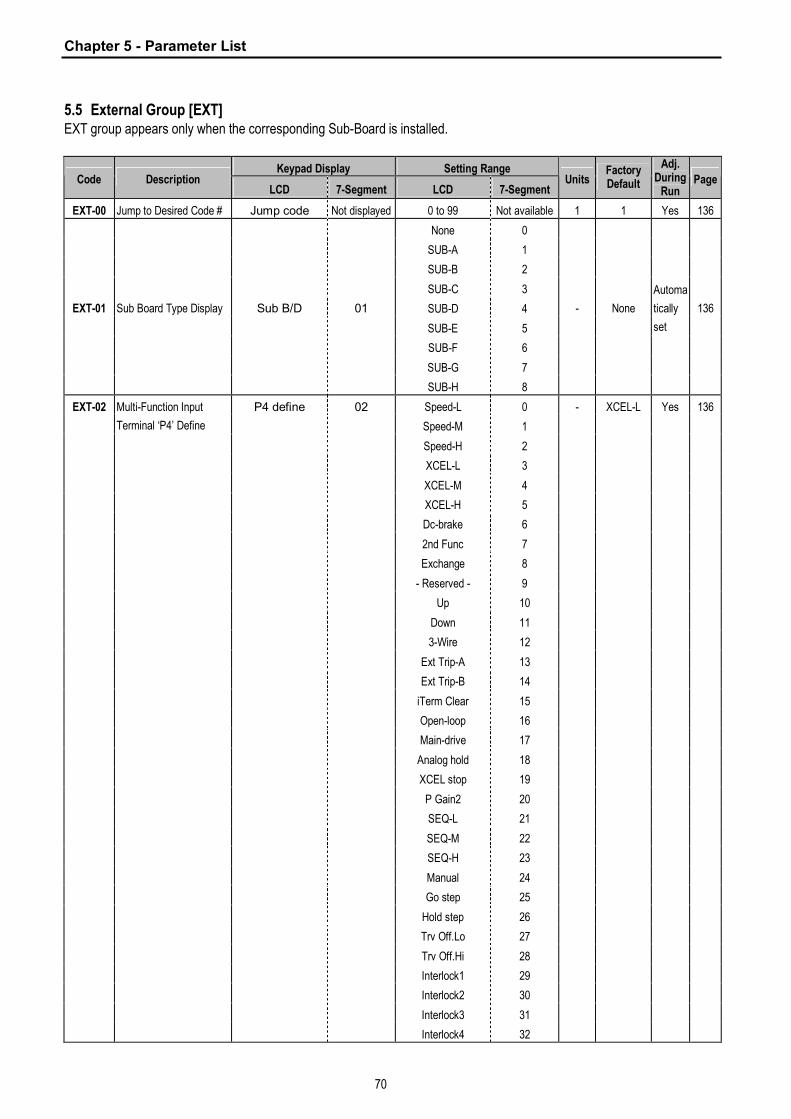
Chapter 5 - Parameter List
70
5.5 External Group [EXT] EXT group appears only when the corresponding Sub-Board is installed.
Keypad Display Setting Range Code Description
LCD 7-Segment LCD 7-Segment Units
Factory Default
Adj. During
Run Page
EXT-00 Jump to Desired Code # Jump code Not displayed 0 to 99 Not available 1 1 Yes 136
None 0
SUB-A 1
SUB-B 2
SUB-C 3
SUB-D 4
SUB-E 5
SUB-F 6
SUB-G 7
EXT-01 Sub Board Type Display Sub B/D 01
SUB-H 8
- None
Automa
tically
set
136
Speed-L 0
Speed-M 1
Speed-H 2
XCEL-L 3
XCEL-M 4
XCEL-H 5
Dc-brake 6
2nd Func 7
Exchange 8
- Reserved - 9
Up 10
Down 11
3-Wire 12
Ext Trip-A 13
Ext Trip-B 14
iTerm Clear 15
Open-loop 16
Main-drive 17
Analog hold 18
XCEL stop 19
P Gain2 20
SEQ-L 21
SEQ-M 22
SEQ-H 23
Manual 24
Go step 25
Hold step 26
Trv Off.Lo 27
Trv Off.Hi 28
Interlock1 29
Interlock2 30
Interlock3 31
EXT-02 Multi-Function Input
Terminal ‘P4’ Define
P4 define 02
Interlock4 32
- XCEL-L Yes 136

Chapter 5 - Parameter List
71
Keypad Display Setting Range Code Description
LCD 7-Segment LCD 7-Segment Units
Factory Default
Adj. During
Run Page
Speed-X 33
Reset 34
BX 35
JOG 36
FX 37
RX 38
Ana Change 39
Pre excite 40
Spd/Trq 41
ASR P/PI 42
EXT-03 Multi-Function Input
Terminal ‘P5’ Define P5 define 03 - XCEL-M Yes
EXT-04 Multi-Function Input
Terminal ‘P6’ Define P6 define 04
Same as Above
- XCEL-H Yes
136
None 0
Override 1 EXT-05 V2 Mode Selection V2 mode 05
Reference 2
- None No 137
EXT-06 Filtering Time Constant
for V2 Input Signal V2 filter 06 0 to 9999 [ms] 1 10 [ms] Yes
EXT-07 V2 Input Minimum
Voltage V2 volt x1 07 0 to V2 volt x2 [V] 0.01 0.00 [V] Yes
EXT-08
Frequency
Corresponding to V2
Input Minimum Voltage
V2 freq y1 08 0 to FU1-20 0.01 0.00 [Hz] Yes
EXT-09 V2 Input Maximum
Voltage V2 volt x2 09 V2 volt x1 to 10 [V] 0.01 10.00 [V] Yes
EXT-10
Frequency
Corresponding to V2
Input Maximum Voltage
V2 freq y2 10 0 to FU1-20 0.01 60.00 [Hz] Yes
137
None 0
Feed-back 1 EXT-12 Usage of Pulse Input
Signal F mode 12
Reference 2
- None No 138
Reverse 0 EXT-13 Real Speed Direction RealSpdDir 13
Forward 1 - - - 138
EXT-14 Encoder Feedback
Frequency ENC FeedBack 14 * [Hz] - - - 138
A+B 0
A 1 EXT-15 Pulse Input Signal
Selection F pulse set 15
- (A+B) 2
- A+B No 139
EXT-16 Encoder Pulse Number F pulse num 16 10 to 4096 1 1024 No 139
EXT-17 Filtering Time Constant
for Pulse Input Signal F filter 17 0 to 9999 [ms] 1 10 [ms] Yes 139
EXT-18 Pulse Input Minimum
Frequency F pulse x1 18 0 to 10 [kHz] 0.01 0.00 [kHz] Yes 139

Chapter 5 - Parameter List
72
Keypad Display Setting Range Code Description
LCD 7-Segment LCD 7-Segment Units
Factory Default
Adj. During
Run Page
EXT-19
Frequency Output
Corresponding to Pulse
Input Minimum
Frequency
F freq y1 19 0 to FU1-20 0.01 0.00 [Hz] Yes
EXT-20 Pulse Input Maximum
Frequency F pulse x2 20 0 to 100 [kHz] 0.01 10.00 [kHz] Yes
EXT-21
Frequency Output
Corresponding to Pulse
Input Maximum
Frequency
F freq y2 21 0 to FU1-20 0.01 60.00 [Hz] Yes
139
EXT-22 P-Gain for ‘Sub-B’ PG P-gain 22 0 to 9999 1 3000 Yes
EXT-23 I-Gain for ‘Sub-B’ PG I-gain 23 0 to 9999 1 50 Yes 140
EXT-24 Slip Frequency for
‘Sub-B’ Board PG Slip Freq 24 0 to 200 [%] 1 100 [%] Yes 140
EXT-25 P-Gain for
(Sensored) Vector_SPD ASR P-Gain 25 10 to 500 [%] 0.1 100.0 [%] Yes
EXT-26 I-Gain for
(Sensored) Vector_SPD ASR I-Gain 26 10 to 9999 [ms] 1 200 [ms] Yes
EXT-27 Forward Torque Limit Trq + Limit 27 0 to 200 [%] 1 180 [%] Yes
EXT-28 Reverse Torque Limit Trq - Limit 28 0 to 200 [%] 1 180 [%] Yes
-
FDT-1 0
FDT-2 1
FDT-3 2
FDT-4 3
FDT-5 4
OL 5
IOL 6
Stall 7
OV 8
LV 9
OH 10
Lost Command 11
Run 12
Stop 13
Steady 14
INV line 15
COMM line 16
Ssearch 17
Step pulse 18
Seq pulse 19
Ready 20
Trv. ACC 21
Trv. DEC 22
MMC 23
Zspd Dect 24
EXT-30 Multi-Function Output
Terminal ‘Q1’ Define Q1 define 30
Torq Dect 25
- FDT-1 Yes 140

Chapter 5 - Parameter List
73
Keypad Display Setting Range Code Description
LCD 7-Segment LCD 7-Segment Units
Factory Default
Adj. During
Run Page
EXT-31 Multi-function Output
Terminal ‘Q2’ Define Q2 define 31 - FDT-2 Yes
EXT-32 Multi-function Output
Terminal ‘Q3’ Define Q3 define 32
Same as Above
- FDT-3 Yes
140
Frequency 0
Current 1
Voltage 2
DC link Vtg 3
EXT-34 LM (Load Meter) Output
Selection LM mode 34
Torque 4
- Current Yes 141
EXT-35 LM Output Adjustment LM adjust 35 10 to 200 [%] 1 100 [%] Yes 141
Frequency 0
Current 1
Voltage 2
DC link Vtg 3
EXT-40 AM1 (Analog Meter 1)
Output Selection AM1 mode 40
Torque 4
- Frequency Yes
EXT-41 AM1 Output Adjustment AM1 adjust 41 10 to 200 [%] 1 100 [%] Yes
Frequency 0
Current 1
Voltage 2
DC link Vtg 3
EXT-42 AM2 (Analog Meter 2)
Output Selection AM2 mode 42
Torque 4
- DC link Vtg Yes
EXT-43 AM2 Output Adjustment AM2 adjust 43 10 to 200 [%] 1 100 [%] Yes
141
EXT-50 Speed Limit Level Speed Limit 44 0 to 100 [%] 0.1 100 [%] No
EXT-51 Speed Limit Bias Speed Bias 45 0 to 200 [%] 0.1 100 [%] No
EXT-52 Speed Limit Gain Speed Gain 46 1 to 10 1 1 No
Reverse 0 EXT-53 Speed Limit Direction Speed Dir 47
Forward 1 - Forward No
142
EXT-54 Zero Speed Detection
Level ZSD Level 48 0 to 120 [Hz] 0.01 2 [Hz] Yes
EXT-55 Zero Speed Detection
Bandwidth ZSD Band 49 0 to 5 [Hz] 0.01 1 [Hz] Yes
144
EXT-56 Torque Detection Level TD Level 50 0 to 150 [%] 0.1 100 [%] Yes
EXT-57 Torque Detection
Bandwidth TD Band 51 0 to 10 [%] 0.1 5 [%] Yes
144
EXT-99 Return Code Not displayed 99 Not available - 1 Yes -

Chapter 5 - Parameter List
74
5.6 Communication Group [COM] COM group appears only when the corresponding Option Boards are installed. Please refer to the option manual for
detail.
Keypad Display Setting Range Code Description
LCD 7-Segment LCD 7-Segment Units
Factory Default
Adj. During
Run Page
COM-00 Jump to Desired Code # Jump code Not displayed 0 to 99 Not available 1 1 Yes
None 0
Device Net 1
Synchro 2
PLC-GF 3
Profibus-DP 4
Digital-In 5
RS485 6
COM-01 Option Board Type Opt B/D 01
Modbus-RTU 7
- None Yes
None 0
Command 1
Freq 2 COM-02 Option Mode Opt Mode 02
Cmd + Freq 3
- None No
COM-03 Option Version Opt Version 03 - - - - No
8 Bit Bin 0
8 BCD 1% 1
8 BCD 1Hz 2
12 Bit Bin 3
12 BCD 0.1% 4
12 BCD 0.1Hz 5
COM-04 Binary Option Input
Selection D-In Mode 04
12 BCD 1Hz 6
- 8 Bit Bin No
COM-05 Binary Input Filter Value Digital Ftr 05 2-50 1 15 Yes
None 0 COM-06
Input Torque Limit
(Option) Opt TrqLmt 06
TrqLmt 1 None Yes
None 0 COM-07
Control Mode Select
(Option) Opt CntlMode 07
Opt Control 1 None No
COM-10 Device Net ID MAC ID 10 0-63 1 0 Yes
125 kbps 0
250 kbps 1 COM-11 Device Net
Communication Speed Baud Rate 11
500 kbps 2
- 125 kbps Yes
20 0
21 1
100 2 COM-12
Device Net Output
Instance Out Instance 12
101 3
- 20 No
70 0
71 1
110 2 COM-13 Device Net Input Instance In Instance 13
111 3
- 70 No
COM-17 PLC Option Station
Number Station ID 17 0 to 63 1 1 Yes
COM-20 Profibus ID Profi MAC ID 20 0 to 127 1 1 Yes
COM-30 Output Number Output Num 30 0 to 8 1 3 Yes
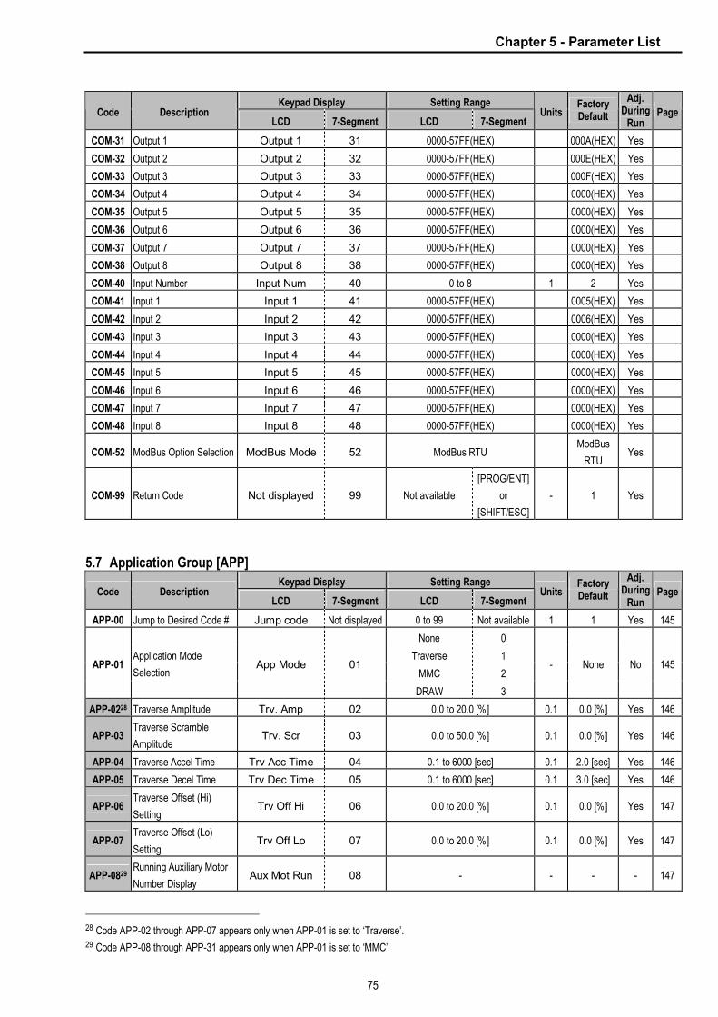
Chapter 5 - Parameter List
75
Keypad Display Setting Range Code Description
LCD 7-Segment LCD 7-Segment Units
Factory Default
Adj. During
Run Page
COM-31 Output 1 Output 1 31 0000-57FF(HEX) 000A(HEX) Yes
COM-32 Output 2 Output 2 32 0000-57FF(HEX) 000E(HEX) Yes
COM-33 Output 3 Output 3 33 0000-57FF(HEX) 000F(HEX) Yes
COM-34 Output 4 Output 4 34 0000-57FF(HEX) 0000(HEX) Yes
COM-35 Output 5 Output 5 35 0000-57FF(HEX) 0000(HEX) Yes
COM-36 Output 6 Output 6 36 0000-57FF(HEX) 0000(HEX) Yes
COM-37 Output 7 Output 7 37 0000-57FF(HEX) 0000(HEX) Yes
COM-38 Output 8 Output 8 38 0000-57FF(HEX) 0000(HEX) Yes
COM-40 Input Number Input Num 40 0 to 8 1 2 Yes
COM-41 Input 1 Input 1 41 0000-57FF(HEX) 0005(HEX) Yes
COM-42 Input 2 Input 2 42 0000-57FF(HEX) 0006(HEX) Yes
COM-43 Input 3 Input 3 43 0000-57FF(HEX) 0000(HEX) Yes
COM-44 Input 4 Input 4 44 0000-57FF(HEX) 0000(HEX) Yes
COM-45 Input 5 Input 5 45 0000-57FF(HEX) 0000(HEX) Yes
COM-46 Input 6 Input 6 46 0000-57FF(HEX) 0000(HEX) Yes
COM-47 Input 7 Input 7 47 0000-57FF(HEX) 0000(HEX) Yes
COM-48 Input 8 Input 8 48 0000-57FF(HEX) 0000(HEX) Yes
COM-52 ModBus Option Selection ModBus Mode 52 ModBus RTU ModBus
RTU Yes
COM-99 Return Code Not displayed 99 Not available
[PROG/ENT]
or
[SHIFT/ESC]
- 1 Yes
5.7 Application Group [APP]
Keypad Display Setting Range Code Description
LCD 7-Segment LCD 7-Segment Units
Factory Default
Adj. During
Run Page
APP-00 Jump to Desired Code # Jump code Not displayed 0 to 99 Not available 1 1 Yes 145
None 0
Traverse 1
MMC 2 APP-01
Application Mode
Selection App Mode 01
DRAW 3
- None No 145
APP-0228 Traverse Amplitude Trv. Amp 02 0.0 to 20.0 [%] 0.1 0.0 [%] Yes 146
APP-03 Traverse Scramble
Amplitude Trv. Scr 03 0.0 to 50.0 [%] 0.1 0.0 [%] Yes 146
APP-04 Traverse Accel Time Trv Acc Time 04 0.1 to 6000 [sec] 0.1 2.0 [sec] Yes 146
APP-05 Traverse Decel Time Trv Dec Time 05 0.1 to 6000 [sec] 0.1 3.0 [sec] Yes 146
APP-06 Traverse Offset (Hi)
Setting Trv Off Hi 06 0.0 to 20.0 [%] 0.1 0.0 [%] Yes 147
APP-07 Traverse Offset (Lo)
Setting Trv Off Lo 07 0.0 to 20.0 [%] 0.1 0.0 [%] Yes 147
APP-0829 Running Auxiliary Motor
Number Display Aux Mot Run 08 - - - - 147
28 Code APP-02 through APP-07 appears only when APP-01 is set to ‘Traverse’. 29 Code APP-08 through APP-31 appears only when APP-01 is set to ‘MMC’.

Chapter 5 - Parameter List
76
Keypad Display Setting Range Code Description
LCD 7-Segment LCD 7-Segment Units
Factory Default
Adj. During
Run Page
APP-09 Starting Aux. Motor
Selection Starting Aux 09 1 to 4 1 1 Yes 147
APP-10 Operation Time Display
on Auto Change Auto Op Time 10 - - - - 147
APP-11 Start Frequency of Aux.
Motor 1 Start freq 1 11 0 to FU1-20 0.01 49.99 [Hz] Yes
APP-12 Start Frequency of Aux.
Motor 2 Start freq 2 12 0 to FU1-20 0.01 49.99 [Hz] Yes
APP-13 Start Frequency of Aux.
Motor 3 Start freq 3 13 0 to FU1-20 0.01 49.99 [Hz] Yes
APP-14 Start Frequency of Aux.
Motor 4 Start freq 4 14 0 to FU1-20 0.01 49.99 [Hz] Yes
147
APP-15 Stop Frequency of Aux.
Motor 1 Stop freq 1 15 0 to FU1-20 0.01 15.00 [Hz] Yes
APP-16 Stop Frequency of Aux.
Motor 2 Stop freq 2 16 0 to FU1-20 0.01 15.00 [Hz] Yes
APP-17 Stop Frequency of Aux.
Motor 3 Stop freq 3 17 0 to FU1-20 0.01 15.00 [Hz]] Yes
APP-18 Stop Frequency of Aux.
Motor 4 Stop freq 4 18 0 to FU1-20 0.01 15.00 [Hz] Yes
148
APP-19 Delay Time before
Operating Aux Motor Aux start DT 19 0 to 9999 [sec] 0.1 60.0 [sec] Yes
APP-20 Delay Time before
Stopping Aux Motor Aux stop DT 20 0 to 9999 [sec] 0.1 60.0 [sec] Yes
148
APP-21 The Number of Aux Motor Nbr Aux’s 21 0 to 4 1 4 Yes 148
No 0 APP-22 PID Bypass Selection Regul Bypass 22
Yes 1 - No Yes 148
APP-23 Sleep Delay Time Sleep Delay 23 0 to 9999 [sec] 0.1 60.0 [sec] Yes 149
APP-24 Sleep Frequency Sleep Freq 24 0 to FU1-20 0.01 0.19 [Hz] Yes 149
APP-25 Wake-Up Level WakeUp Level 25 0 to 100 [%] 1 35.0 [%] Yes 149
APP-26 Auto Change Mode
Selection AutoCh-Mode 26 0 to 2 1 1 Yes 149
APP-27 Auto Change Time AutoEx-intv 27 00:00 to 99:00 00:01 72:00 Yes
APP-28 Auto Change Level AutoEx-level 28 0 to 100 [%] 0.1 20 [%] Yes 150
No 0 APP-29 Inter-Lock Selection Inter-lock 29
Yes 1 - No Yes 150
APP-30 Feedback Freq/
Percentage Display Fbk/PER 30 [Hz] / [%] - 150
APP-31 Actual Value Display Prs 31 [Bar]/[Pa] - - - - 151
APP-32 Pressure Display Scale Scale Disp 32 0 to 50000 - 1000 Yes 151
None 0
V1_Draw 1
I_Draw 2 APP-3330 Draw Mode Selection Draw Mode 33
V2_Draw 3
- None Yes 151
APP-34 Draw Size Setting DrawPerc 34 0 to 150 [%] 0.1 100 [%] Yes 151
30 Code APP-32 through APP-33 appears only when APP-01 is set to ‘Draw’.

Chapter 5 - Parameter List
77
5.8 Sub-Board Selection Guide According To Function Sub-Board Type
Code Function Description LCD Display SUB-A Board SUB-B Board SUB-C Board
EXT-02 Multi-function Input Terminal ‘P4’ P4 define ● ●
EXT-03 Multi-function Input Terminal ‘P5’ P5 define ● ●
EXT-04 Multi-function Input Terminal ‘P6’ P6 define ● ●
EXT-05 V2 Mode Selection V2 mode ● ●
EXT-06 Filtering Time Constant for V2 Input Signal V2 filter ● ●
EXT-07 V2 Input Minimum Voltage V2 volt x1 ● ●
EXT-08 Frequency Corresponding to V2 Input
Minimum Voltage V2 freq y1 ● ●
EXT-09 V2 Input Maximum Voltage V2 volt x2 ● ●
EXT-10 Frequency Corresponding to V2 Input
Maximum Voltage V2 freq y2 ● ●
EXT-14 Usage for Pulse Input Signal F mode ●
EXT-15 Pulse Input Signal Selection F pulse set ●
EXT-16 Encoder Pulse Selection F pulse num ●
EXT-17 Filtering Time Constant for Pulse Input Signal F filter ●
EXT-18 Pulse Input Minimum Frequency F pulse x1 ●
EXT-19 Frequency Output corresponding to Pulse
Input Minimum Frequency F freq y1 ●
EXT-20 Pulse Input Maximum Frequency F pulse x2 ●
EXT-21 Frequency Output corresponding to Pulse
Input Maximum Frequency F freq y2 ●
EXT-22 P-Gain for PG Option PG P-gain ●
EXT-23 I-Gain for PG Option PG I-gain ●
EXT-24 Slip Frequency for PG Option PG Slip freq ●
EXT-30 Multi-function Output Terminal ‘Q1’ Q1 define ● ●
EXT-31 Multi-function Output Terminal ‘Q2’ Q2 define ●
EXT-32 Multi-function Output Terminal ‘Q3’ Q3 define ●
EXT-34 LM (Load Meter) Output Selection LM mode ●
EXT-35 LM Output Adjustment LM adjust ●
EXT-40 AM1 (Analog Meter 1) Output Selection AM1 mode ●
EXT-41 AM1 Output Adjustment AM1 adjust ●
EXT-42 AM2 (Analog Meter 2) Output Selection AM2 mode ●
EXT-43 AM2 Output Adjustment AM2 adjust ●
EXT-50 Speed Limit Level Speed Limit ●
EXT-51 Speed Limit Bias Speed Bias ●
EXT-52 Speed Limit Gain Speed Gain ●
EXT-53 Speed Limit Direction Speed Dir ●
EXT-54 Zero Speed Detection Level ZSD Level ●
EXT-55 Zero Speed Detection Bandwidth ZSD Band ●
EXT-56 Torque Detection Level TD Level ●
EXT-57 Torque Detection Bandwidth TD Band ●

Chapter 5 - Parameter List
78
Notes:

79
CHAPTER 6 - PARAMETER DESCRIPTION
6.1 Drive group [DRV]
DRV-00: Command Frequency or Command Torque/ Output Current (LCD)
* In Torque mode: LCD display - Cmd. Trq
7 Segment - r (Rpm) l In FU2-39 [Control Mode Selection], 4
(Sensorless_T) 6 (Vector_TRQ) is torque mode. l DRV-00 [Command Frequency or Command
Torque] has two functions. 1) Digital frequency setting - When DRV-04 [Frequency or Torque Mode] is set to 0 (KeyPad-1) or 1 (KeyPad-2), command freq is not settable above FU1-20 [Maximum Frequency]. 2) Monitoring function setting - Command frequency displayed during stop - Output current/frequency displayed during run. Analog/digital frequency command setting in DRV-04 [Frequency or Torque Mode]: l DRV-04 [Frequency or Torque Mode] is set to 2
(V1),3 (I) or 4 (V1+I), frequency command is set via I/O-01~10 [Analog Frequency command/Torque]. Refer to I/O-01~10 for detail description.
l DRV-16 [Speed Unit Selection] is set to 1 (Rpm), speed is displayed in Rpm.
l If FU2-39 is set to 4 (Sensorless_T) or 6 (Vector_TRQ), speed is displayed as the percent [%] to the rated torque. Torque command is settable in DRV-04 [Frequency or Torque Mode].
* Factory default setting = 100[%] (Up to 150[%] settable)
l Setting the DRV-04 [Frequency or Torque Mode] ☞ Note: In torque mode, speed unit is automatically
displayed in [%].
Setti
ng DRV-04
Parameter
Name Programming Description
0 KeyPad-1
1. In DRV-00, press the [PROG]
key. 2. Enter the desired freq. 3.
Press the [ENT] key to write the
new value into memory.
1 KeyPad-2
Digital freq.
command
1. In DRV-00, press the [PROG]
key. 2. Press the [ñ(Up)] or
[ò(Down)] key to set the desired
freq., while the inverter keeps
running. 3. Press the [ENT] key
to write the new value into
memory.
2 V1
Control terminal “V1” Voltage
analog input (0 to 10V)
See the description of I/O-01~05.
3 I
Control terminal “I” Current
analog input (4 to 20mA)
See the description of I/O-06~10.
4 V1+I
Analog
freq.
command
Control terminal “V1”+“I”
(0-10V/4-20mA) Analog input.
See the description of I/O-01~10.
l Command Freq/Torque setting via “V1” input terminal when set DRV-04 [Frequency/Torque mode] to 2 (V1) or 4 (V1+I)
Code Default setting Setting range I/O-01 10 [msec] 0 ~ 10000 [msec] I/O-02 0 [V] 0 ~ 10 [V] I/O-03 0 [Hz] 0 ~ Max. freq I/O-04 10 [V] 0 ~ 10 [V] I/O-05 60 [Hz] 0 ~ Max freq
DRV► Cmd. Freq* 00 0.00 Hz
0.00
F *
Factory Default: 0.00 Hz 0.00

Chapter 6 - Parameter Description [DRV]
80
Code Keypad Display Parameter Name
I/O-01 V1 filter Filter Time Constant for V1
Signal Input
I/O-02 V1 volt x1 V1 Input
Minimum Voltage
I/O-03 V1 freq y1 Frequency Corresponding to V1 Input Minimum Voltage
I/O-04 V1 volt x2 V1 Input Maximum Voltage
I/O-05 V1 freq y2 Frequency Corresponding to V1
Input Maximum Voltage
è Important: Increase I/O-01-[Filter Time Constant for V1
Signal Input] if the V1 signal is affected by noise causing
unstable operation. Increasing this value makes
response time slower.
I/O-06~10 [Analog Current Input “ I “ Signal adjustment] l Command Freq/Torque setting via “I” input terminal
when set DRV-04 [Frequency/Torque mode] to 3 (I) or 4 (V1+I)
Code Default setting Setting range I/O-06 10 [msec] 0 ~ 10000 [msec] I/O-07 4 [mA] 0 ~ 20 [mA] I/O-08 0 [Hz] 0 ~ Max. freq
I/O-09 20 [mA] 0 ~ 20 [mA] I/O-10 60 [Hz] 0 ~ Max. freq
Code Keypad display Parameter Name
I/O-06 I filter Filter time constant for I signal
Input I/O-07 I curr x1 I Input Minimum Current
I/O-08 I freq y1 Frequency Corresponding to I
Input Minimum Current I/O-09 I curr x2 I Input Maximum Current
I/O-10 I freq y2 Frequency Corresponding to I
Input Maximum Current
è Important: Increase I/O-06-[Filter time constant for I
signal Input] if the I signal is affected by noise causing
unstable operation. Increasing this value makes
response time slower.
DRV-01: Acceleration Time
V1 analog input (0~10V)
Set freq.
I/O-02
V1 Minimum V
I/O-03
I/O-05
I/O-04
V1 Maximum V
Terminal I ( 0 ~ 20 mA )
Set freq
I/O-07 I Minimum
current
I/O-08
I/O-10
I/O-09 I Maximum
current
DRV► Acc. time 01 20.0 sec
20.0
01
Factory Default: 20.0 sec 20.0
Related Functions: DRV-04 [Frequency or Torque Mode] DRV-16 [Speed Unit Selection] FU1-20 [Maximum Frequency] FU2-39 [Control Mode Selection]
I/O-1~10 [Analog Frequency Command/Torque]

Chapter 6 - Parameter Description [DRV]
81
DRV-02: Deceleration Time
The inverter targets the FU2-70 when accelerating or
decelerating. When the FU2-70 is set to “Maximum
Frequency”, the acceleration time is the time taken by
the motor to reach FU1-20 from 0 Hz. The deceleration
time is the time taken by the motor to reach 0 Hz from
FU1-20 [Maximum Frequency].
When the FU2-70 is set to ‘Delta Frequency’, the
acceleration and deceleration time is the time taken to
reach a targeted frequency (instead the maximum
frequency) from a frequency.
The acceleration and deceleration time can be changed
to a preset transient time via multi-function inputs. By
setting the multi-function inputs (P1, P2, P3) to ‘XCEL-L’,
‘XCEL-M’, ‘XCEL-H’ respectively, the Accel and Decel
time set in I/O-25 to I/O-38 are applied according to the
binary inputs of the P1, P2, P3.
☞ Note: I/O-12 to I/O-14: Sets the terminal function of P1, P2, P3 terminal inputs.
Code LCD
display Description
XCEL-
H
XCEL-
M
XCEL-
L
Factory
setting
DRV-
01 Acc time Acc time 0 0 0 0 10 sec
DRV-
02 Dec time Dec time 0 0 0 0 20 sec
I/O-25 ACC-1 Acc time 1 0 0 1 20 sec
I/O-26 DEC-1 Dec time 1 0 0 1 20 sec
I/O-27 ACC-2 Acc time 2 0 1 0 30 sec
I/O-28 DEC-2 Dec time 2 0 1 0 30 sec
I/O-29 ACC-3 Acc time 3 0 1 1 40 sec
I/O-30 DEC-3 Dec time 3 0 1 1 40 sec
I/O-31 ACC-4 Acc time 4 1 0 0 50 sec
I/O-32 DEC-4 Dec time 4 1 0 0 50 sec
I/O-33 ACC-5 Acc time 5 1 0 1 40 sec
I/O-34 DEC-5 Dec time 5 1 0 1 40 sec
I/O-35 ACC-6 Acc time 6 1 1 0 30 sec
I/O-36 DEC-6 Dec time 6 1 1 0 30 sec
I/O-37 ACC-7 Acc time 7 1 1 1 20 sec
I/O-38 DEC-7 Dec time 7 1 1 1 20 sec
FU2-71 [Accel/Decel time scale]
l Set the Accel / Decel time unit.
Setting Unit Description
0 0.01 sec Minimum 0 sec settable
Maximum 60 sec settable
1 0.1 sec
Minimum 0 sec settable
Maximum 600 sec settable
(Factory setting)
2 1 sec Minimum 0 sec settable
Maximum 6000 sec settable*
* Up to 6000 sec setting is available via LE-200 keypad.
DRV-03: Drive Mode (Run/Stop Method)
Select the source of run/stop command.
Setting Range
LCD 7-Seg Description
Keypad 0 Run/Stop is controlled by Keypad.
Fx/Rx-1 1 Control Terminals FX, RX and 5G control Run/Stop. (Method 1)
Fx/Rx-2 2 Control Terminals FX, RX and 5G control Run/Stop. (Method 2)
DRV► Dec. time 02 30.0 sec 30.0
02
Factory Default: 30.0 sec 30.0
Related Functions: FU1-20 [Max freq] FU2-70 [Reference freq. for Accel/Decel] FU2-71 [Accel/Decel time scale] I/O-12 to I/O-14 [Multi-function input terminal P1, P2, P3] I/O-25 to I/O-38 [Acc/Dec time for step frequency] n FU2-70: Selects the frequency to be targeted for acceleration
and deceleration. [Max Freq, Delta Freq] n FU2-71: Selects the time scale. [0.01, 0.2, 1] n I/O-12 to I/O-14: Sets the terminal function of P1, P2, P3
terminal inputs. n I/O-25 to I/O-38: Presets the Accel/Decel time activated via
multifunction inputs (P1, P2, P3)
Output Frequency
Max. Freq.
Time
Acc. time Dec. time
DRV► Drive mode
03 Keypad 1
03
Factory Default: Fx/Rx-1 1

Chapter 6 - Parameter Description [DRV]
82
[Drive Mode: ‘Fx/Rx-1’]
[Drive Mode: ‘Fx/Rx-2’]
DRV-04: Frequency or Torque Mode (Frequency / Torque Setting Method)
* In Torque mode: LCD display: “Torque mode”
7 Segment: “04”
l If the DRV-04 [Frequency or Torque Mode] is set to 2 (V1), 3 (I), 4 (V1+I), see the description of I/O-01~10 [Analog Voltage/Current input signal adjustment].
l If FU2-39 is set to 4 (Sensorless_T) or 6 (Vector_TRQ), speed is displayed as the percent [%] to the rated torque. Torque command is settable in DRV-04 [Frequency or Torque Mode].
l DRV-04 setting value is separately saved according to which control mode (Speed or Torque) is selected in FU2-39 [Control mode selection].
Setting Range
LCD 7-Seg Description
Keypad-1 0
Frequency is set at DRV-00. The frequency is changed by pressing PROG key and entered by pressing ENT key. The inverter does not output the changed frequency until the ENT key is pressed.
Keypad-2 1
Frequency is set at DRV-00. Press PROG key and then by pressing the ▲, ▼ key, the inverter immediately outputs the changed frequency. Pressing the ENT key saves the changed frequency.
V1 2 Input the frequency reference (0-10V) to the “V1” control terminal. Refer to the I/O-01 to I/O-05 for scaling the signal.
I 3 Input the frequency reference (4~20mA) to the “I” control terminal. Refer to the I/O-06 to I/O-10 for scaling the signal.
V1+I 4 Input the frequency reference (0~10V, 4~20mA) to the “V1”,“I” control terminals. The ‘V1’ signal overrides the ‘I’ signal.
Output Frequency
FX-CM
Time
ON
RX-CM ON
Forward
Reverse
Forward Run
Reverse Run
Output Frequency
FX-CM
Time
ON
RX-CM ON
Forward
Reverse
Run/Stop
Direction
DRV► Freq mode*
04 Keypad-1 0
04
Factory Default: Keypad-1 0
DRV ▶ Cmd. Freq
00 00.00 Hz
DRV ▶ Cmd. Trq
00 0.0 %
[Initial screen of Torque Mode]
[Initial screen of Frequency Mode]

Chapter 6 - Parameter Description [DRV]
83
[Freq Mode: ‘V1’]
[Freq Mode: ‘I’]
[Freq Mode: V1+’I’]
DRV-05 ~ DRV-07: Step Frequency 1 ~ 3
The inverter outputs preset frequencies set in these
codes according to the multi-function terminals
configured as ‘Speed-L’, ‘Speed-M’ and ‘Speed-H’. The
output frequencies are decided by the binary
combination of P1, P2, P3 configured in I/O-12 to I/O-17.
Refer to the following table for the preset frequency
outputs.
Binary Combination of
P1, P2, P3 Speed-L Speed-M Speed-H
Output Frequency
Step Speed
0 0 0 DRV-00 Speed 0 1 0 0 DRV-05 Speed 1 0 1 0 DRV-06 Speed 2 1 1 0 DRV-07 Speed 3
[Step Frequency Output]
Output Frequency
Analog Signal Input (V1)
Freq. max
0V 10V
Reference Freq. Range
Output Frequency
Freq. Max
4mA 20mA
Reference Freq. Range
Analog Signal Input (I)
Output Frequency
Freq. Max
0V+4mA
Reference Freq. Range
10V+20mA
Analog Signal Input (‘V1+I’)
DRV► Step freq-1 05 10.00 Hz
10.00
05
Factory Default: 10.00 Hz 10.00
DRV► Step freq-2
06 20.00 Hz 20.00
06
Factory Default: 20.00 Hz 20.00
DRV► Step freq-3
07 30.00 Hz 30.00
07
Factory Default: 30.00 Hz 30.00
P1-CM ON
Output Frequency
Time
Time
P2-CM ON Time
P3-CM Time
ON
Speed 3
Speed 0
Speed 2
Speed 1
Related functions: DRV-00 [Digital Command Frequency or Command Torque]
FU2~39 [Control Mode Selection] I/O-01~10 [Analog Voltage/Current input signal adjustment]

Chapter 6 - Parameter Description [DRV]
84
☞ Note: The frequency setting method of ‘Speed 0’ is
decided by DRV-04.
DRV-08: Output Current
This code displays the output current of the inverter in
RMS.
DRV-09: Motor Speed
This code displays the motor speed in RPM while the
motor is running.
Use the following equation to scale the mechanical
speed using FU2-74 [Gain for Motor Speed display] if
you want to change the motor speed display to rotation
speed (r/min) or mechanical speed (m/min).
Motor speed = 120 * (F/P) * FU2-74
Where, F= Output Frequency and P= the Number of Motor Poles
DRV-10: DC Link Voltage
This code displays the DC link voltage inside the inverter.
DRV-11: User Display Selection
This code displays the parameter selected in FU2-73
[User Display]. There are types of parameters in FU2-73:
Voltage, Watt and Torque.
DRV-12: Fault Display
This code displays the current fault (trip) status of the inverter. Use the PROG, ▲ and ▼ key before pressing
the RESET key to check the fault content(s), output
frequency, output current, and whether the inverter was
accelerating, decelerating, or in constant speed at the time of the fault occurred. Press the ENT key to exit.
The fault content will be stored in FU2-01 to FU2-05 when the RESET key is pressed. For more detail,
please refer to Chapter 7.
[Fault Contents] Keypad display
Fault (Trip) LCD 7-Segment
Over-Current 1 Over Current
1 OC
Over-Voltage Over Voltage OV
External Trip Input A External-A EXTA
Emergency Stop (Not Latched) BX BX
Low-Voltage Low Voltage LV
Fuse Open Fuse Open FUSE
Ground Fault Ground Fault GF
Over-Heat on Heat sink Over Heat OH
Electronic Thermal Trip E-Thermal ETH
Over-Load Trip Over Load OLT
Inverter H/W Fault - EEP Error - ADC Offset - WDOG Error - In-Phase Open
HW-Diag HW
External Trip Input B External-B EXTB
Over-Current 2 Arm Short ASHT
Option Error Option OPT
Output Phase Loss Phase Open PO
Inverter Over-Load Inv. OLT IOLT
DRV► Current 08 0.0 A
0.0
08
Factory Default: 0.0 A 0.0
DRV► Speed 09 0rpm
0
09
Factory Default: 0rmp 0
Related Functions: I/O-12 to I/O-14 [Reference Inputs] I/O-17 [Filtering Time Constant] I/O-21 to I/O-21 [Step Frequency 4~7] n I/O-01 to I/O-10: Scaling the analog input signals (V1 and I)
for frequency reference. n I/O-17: Adjusts the response sensibility of the input terminal
to eliminate contact noise. n I/O-21 to I/O-24: Sets the step frequency from 4 to 7.
DRV► DC link vtg
10 ----- V ----
10
Factory Default: ---- V ----
DRV► User disp
11 Out 0.0 V 0.0
11
Factory Default: 0.0 V 0.0
DRV► Fault 12 None
nOn
12
Factory Default: None nOn
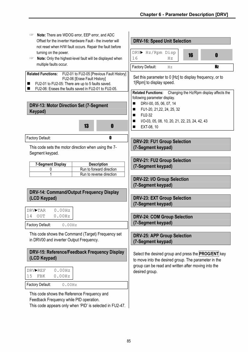
Chapter 6 - Parameter Description [DRV]
85
☞ Note: There are WDOG error, EEP error, and ADC
Offset for the inverter Hardware Fault - the inverter will
not reset when H/W fault occurs. Repair the fault before
turning on the power.
☞ Note: Only the highest-level fault will be displayed when
multiple faults occur.
DRV-13: Motor Direction Set (7-Segment Keypad)
This code sets the motor direction when using the 7-
Segment keypad.
7-Segment Display Description
0 Run to forward direction 1 Run to reverse direction
DRV-14: Command/Output Frequency Display (LCD Keypad)
This code shows the Command (Target) Frequency set
in DRV00 and inverter Output Frequency.
DRV-15: Reference/Feedback Frequency Display (LCD Keypad)
This code shows the Reference Frequency and
Feedback Frequency while PID operation.
This code appears only when ‘PID’ is selected in FU2-47.
DRV-16: Speed Unit Selection
Set this parameter to 0 [Hz] to display frequency, or to 1[Rpm] to display speed.
DRV-20: FU1 Group Selection (7-Segment keypad)
DRV-21: FU2 Group Selection (7-Segment keypad)
DRV-22: I/O Group Selection (7-Segment keypad)
DRV-23: EXT Group Selection (7-Segment keypad)
DRV-24: COM Group Selection (7-Segment keypad)
DRV-25: APP Group Selection (7-Segment keypad)
Select the desired group and press the PROG/ENT key
to move into the desired group. The parameter in the
group can be read and written after moving into the
desired group.
Related Functions: FU2-01 to FU2-05 [Previous Fault History] FU2-06 [Erase Fault History] n FU2-01 to FU2-05: There are up to 5 faults saved. n FU2-06: Erases the faults saved in FU2-01 to FU2-05.
0
13
Factory Default: 0
DRV►TAR 0.00Hz 14 OUT 0.00Hz
Factory Default: 0.00Hz
DRV►REF 0.00Hz 15 FBK 0.00Hz
Factory Default: 0.00Hz
Related Functions: Changing the Hz/Rpm display affects the following parameter display.
n DRV-00, 05, 06, 07, 14
n FU1-20, 21,22, 24, 25, 32
n FU2-32
n I/O-03, 05, 08, 10, 20, 21, 22, 23, 24, 42, 43 n EXT-08, 10
DRV► Hz/Rpm Disp 16 Hz
0
16
Factory Default: Hz Hz

Chapter 6 - Parameter Description [DRV]
86
Notes:
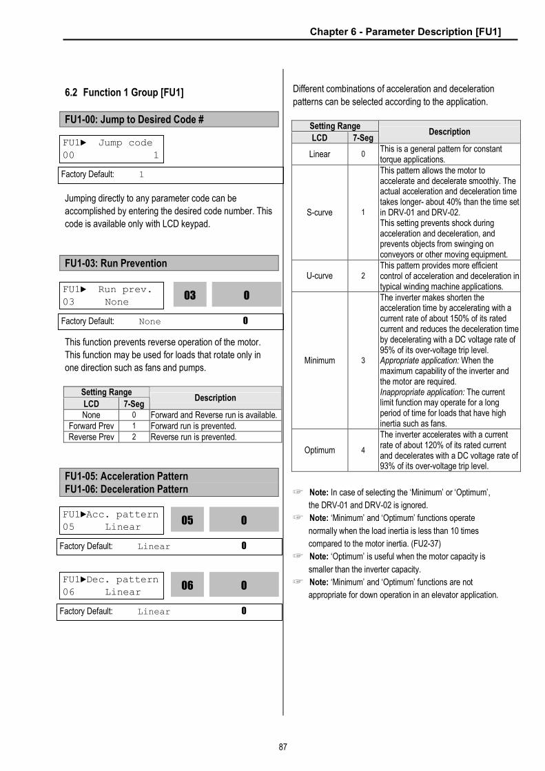
Chapter 6 - Parameter Description [FU1]
87
6.2 Function 1 Group [FU1]
FU1-00: Jump to Desired Code #
Jumping directly to any parameter code can be
accomplished by entering the desired code number. This
code is available only with LCD keypad.
FU1-03: Run Prevention
This function prevents reverse operation of the motor.
This function may be used for loads that rotate only in
one direction such as fans and pumps.
Setting Range
LCD 7-Seg Description
None 0 Forward and Reverse run is available. Forward Prev 1 Forward run is prevented. Reverse Prev 2 Reverse run is prevented.
FU1-05: Acceleration Pattern FU1-06: Deceleration Pattern
Different combinations of acceleration and deceleration
patterns can be selected according to the application.
Setting Range
LCD 7-Seg Description
Linear 0 This is a general pattern for constant torque applications.
S-curve 1
This pattern allows the motor to accelerate and decelerate smoothly. The actual acceleration and deceleration time takes longer- about 40% than the time set in DRV-01 and DRV-02. This setting prevents shock during acceleration and deceleration, and prevents objects from swinging on conveyors or other moving equipment.
U-curve 2 This pattern provides more efficient control of acceleration and deceleration in typical winding machine applications.
Minimum 3
The inverter makes shorten the acceleration time by accelerating with a current rate of about 150% of its rated current and reduces the deceleration time by decelerating with a DC voltage rate of 95% of its over-voltage trip level. Appropriate application: When the maximum capability of the inverter and the motor are required. Inappropriate application: The current limit function may operate for a long period of time for loads that have high inertia such as fans.
Optimum 4
The inverter accelerates with a current rate of about 120% of its rated current and decelerates with a DC voltage rate of 93% of its over-voltage trip level.
☞ Note: In case of selecting the ‘Minimum’ or ‘Optimum’,
the DRV-01 and DRV-02 is ignored.
☞ Note: ‘Minimum’ and ‘Optimum’ functions operate
normally when the load inertia is less than 10 times
compared to the motor inertia. (FU2-37)
☞ Note: ‘Optimum’ is useful when the motor capacity is
smaller than the inverter capacity.
☞ Note: ‘Minimum’ and ‘Optimum’ functions are not
appropriate for down operation in an elevator application.
FU1► Jump code 00 1
Factory Default: 1
FU1► Run prev. 03 None
0
03
Factory Default: None 0
FU1►Acc. pattern 05 Linear
0
05
Factory Default: Linear 0
FU1►Dec. pattern 06 Linear
0
06
Factory Default: Linear 0

Chapter 6 - Parameter Description [FU1]
88
[Accel/Decel Pattern: ‘Linear’]
[Accel/Decel Pattern: ‘S-curve’]
[Accel/Decel Pattern: ‘U-curve’]
FU1-07: Stop Mode
Sets the stopping method for the inverter.
Setting Range
LCD 7-Seg Description
Decel 0 Inverter stops by the deceleration pattern.
Dc-brake 1
Inverter stops with DC injection braking. Inverter outputs DC voltage when the frequency reached the DC injection braking frequency set in FU1-08 during decelerating.
Free-run (Coast to stop)
2 Inverter cuts off its output immediately when the stop signal is commanded.
[Stop Mode: ‘Decel’]
[Stop Mode: ‘Dc-brake’]
Output Frequency
Time
Acc. Pattern Dec. Pattern
Output Frequency
Time
Acc. Pattern Dec. Pattern
Output Frequency
Time
Acc. Pattern Dec. Pattern
FU1► Stop mode 07 Decel
0
07
Factory Default: Decel 0
Output Frequency
Time
FX-CM ON
Output Voltage
Time
Time
Stop Command
Output Frequency
Time
FX-CM ON
Output Voltage
Time
Time
Stop Command
FU1-08
FU1-10 [DCBr Value]
t1 t2
t1: FU1-09
t2: FU1-11

Chapter 6 - Parameter Description [FU1]
89
[[Stop Mode: ‘Free-run’]
FU1-08: DC Injection Braking Frequency FU1-09: DC Injection Braking On-delay Time FU1-10: DC Injection Braking Voltage FU1-11: DC Injection Braking Time
By introducing a DC voltage to the motor windings this
function stops the motor immediately. Selecting ‘DC-
Brake’ in FU1-07 activates FU1-08 through FU1-11.
FU1-08 [DC Injection Braking Frequency] is the
frequency at which the inverter starts to output DC
voltage during deceleration.
FU1-09 [DC Injection Braking On-delay Time] is the
inverter output blocking time before DC injection braking.
FU1-10 [DC Injection Braking Voltage] is the DC voltage
applied to the motor and is based on FU2-33 [Rated
Current of Motor].
FU1-11 [DC Injection Braking Time] is the time the DC
current is applied to the motor.
[DC Injection Braking Operation]
Output Frequency
Time
FX-CM ON
Output Voltage
Time
Time
Stop Command
Output Cutoff
Output Cutoff
FU1► DcBr freq 08 5.00 Hz
5.00
08
Factory Default: 5.00 Hz 5.00
FU1► DcBlk time
09 0.10 sec 0.10
09
Factory Default: 0.10 sec 0.10
FU1► DcBr value
10 50 % 50
10
Factory Default: 50 % 50
FU1► DcBr time 11 1.0 sec
1.0
11
Factory Default: 1.0 sec 1.0
Output Frequency
Time
FX-CM ON
Output Voltage
Time
Time
Stop Command
FU1-08 [DCBr Freq]
FU1-10 [DCBr Value]
t1 t2
t1: FU1-09
t2: FU1-11

Chapter 6 - Parameter Description [FU1]
90
FU1-12: Starting DC Injection Braking Time FU1-13: Staring DC Injection Braking Time
Inverter holds the starting frequency for Starting DC
Injection Braking Time. It outputs DC voltage to the
motor for FU1-13 [Starting DC Injection Braking Time]
with the FU1-12 [Starting DC Injection Braking Voltage]
before accelerating.
[Starting DC Injection Braking Operation]
☞ Note: The DC injection braking function does not function
when either FU1-12 or FU1-13 is set to “0”.
☞ Note: FU1-12 [Starting DC Injection Braking Voltage] is
also used as the DC Injection Braking Voltage for the
multifunction input when the multifunction input is set to
“DC braking”.
FU1-14: Pre-excitation Time
When you set ON to the operation command (FWD,
REV), the inverter conducts pre-exciting automatically
for the time specified by this parameter. l After FU1-14 [Pre-excitation Time] elapses the
inverter starts normal operation in the following graph.
Code LCD display Factory setting Setting range
FU1-14 PreExTime 1 [sec] 0 ~ 60 [sec]
FU1► DcSt value 12 50 %
50
12
Factory Default: 50 % 50
FU1► DcSt time
13 0.0 sec 0.0
13
Factory Default: 0.0 sec 0.0
Output Frequency
Time
FX-CM ON
Output Voltage
Time
Time
Run Command
FU1-22
FU1-12
t1 t1: FU1-13 [Starting DC Injection Braking Time]
Output Current
Time
Related Functions: FU2-33 [Rated Current of Motor] n FU2-33: the DC current is limited by this parameter.
FX-CM
Output freq [Hz]
Output
voltage [V]
T1 = Pre-excitation time
Related function: FU2-34 [No Load Motor Current (RMS)]
FU1-16 [Pre-excitation Current]
FU1► PreExTime 14 1.0 sec
1.0
14
Factory Default: 1.0 sec 1.0
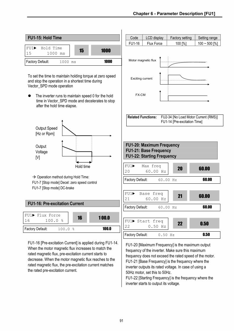
Chapter 6 - Parameter Description [FU1]
91
FU1-15: Hold Time
To set the time to maintain holding torque at zero speed and stop the operation in a shortest time during Vector_SPD mode operation l The inverter runs to maintain speed 0 for the hold
time in Vector_SPD mode and decelerates to stop after the hold time elapse.
à Operation method during Hold Time:
FU1-7 [Stop mode] Decel: zero speed control
FU1-7 [Stop mode] DC-brake
FU1-16: Pre-excitation Current
FU1-16 [Pre-excitation Current] is applied during FU1-14.
When the motor magnetic flux increases to match the
rated magnetic flux, pre-excitation current starts to
decrease. When the motor magnetic flux reaches to the
rated magnetic flux, the pre-excitation current matches
the rated pre-excitation current.
Code LCD display Factory setting Setting range
FU1-16 Flux Force 100 [%] 100 ~ 500 [%]
FU1-20: Maximum Frequency FU1-21: Base Frequency FU1-22: Starting Frequency
FU1-20 [Maximum Frequency] is the maximum output
frequency of the inverter. Make sure this maximum
frequency does not exceed the rated speed of the motor.
FU1-21 [Base Frequency] is the frequency where the
inverter outputs its rated voltage. In case of using a
50Hz motor, set this to 50Hz.
FU1-22 [Starting Frequency] is the frequency where the
inverter starts to output its voltage.
Output
Voltage
[V]
Output Speed [Hz or Rpm]
Hold time
FX-CM
Motor magnetic flux
Exciting current
FU1► Max freq
20 60.00 Hz 60.00
20
Factory Default: 60.00 Hz 60.00
FU1► Base freq 21 60.00 Hz
60.00
21
Factory Default: 60.00 Hz 60.00
FU1► Start freq 22 0.50 Hz
0.50
22
Factory Default: 0.50 Hz 0.50
FU1► Hold Time 15 1000 ms
1000
15
Factory Default: 1000 ms 1000
FU1► Flux Force 16 100.0 %
1 00.0
16
Factory Default: 100.0 % 100.0
Related Functions: FU2-34 [No Load Motor Current (RMS)] FU1-14 [Pre-excitation Time]
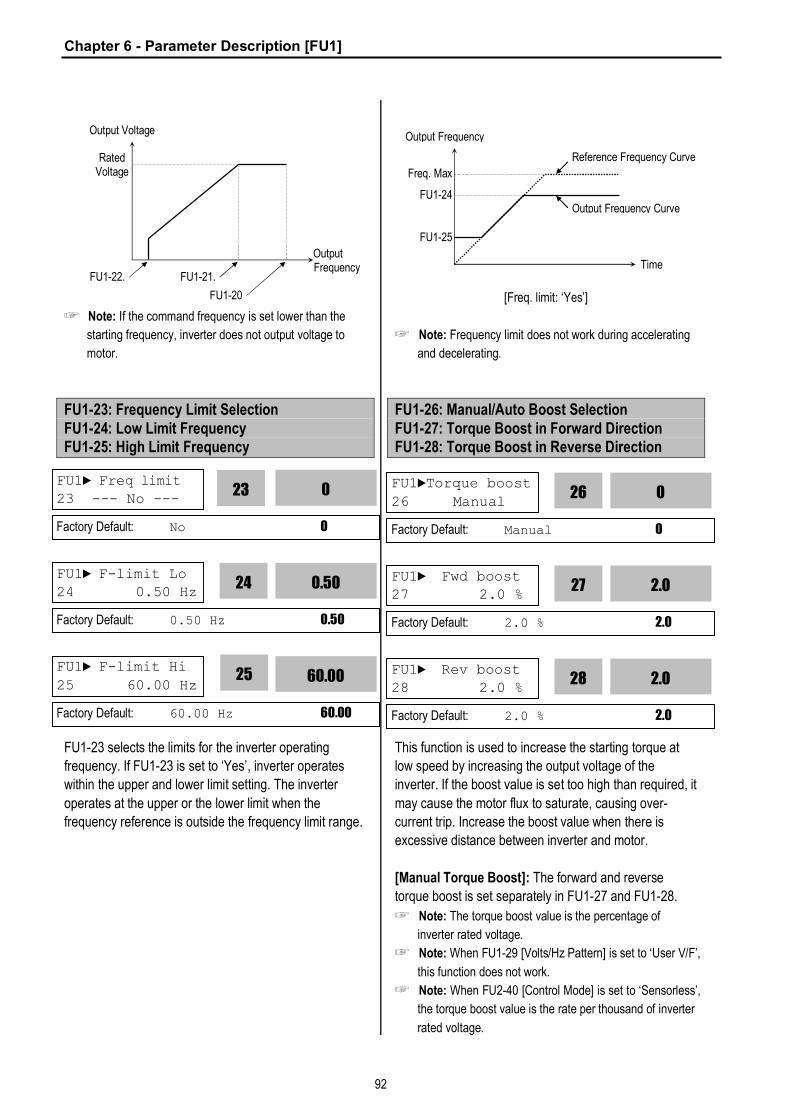
Chapter 6 - Parameter Description [FU1]
92
☞ Note: If the command frequency is set lower than the
starting frequency, inverter does not output voltage to
motor.
FU1-23: Frequency Limit Selection FU1-24: Low Limit Frequency FU1-25: High Limit Frequency
FU1-23 selects the limits for the inverter operating
frequency. If FU1-23 is set to ‘Yes’, inverter operates
within the upper and lower limit setting. The inverter
operates at the upper or the lower limit when the
frequency reference is outside the frequency limit range.
[Freq. limit: ‘Yes’]
☞ Note: Frequency limit does not work during accelerating
and decelerating.
FU1-26: Manual/Auto Boost Selection FU1-27: Torque Boost in Forward Direction FU1-28: Torque Boost in Reverse Direction
This function is used to increase the starting torque at
low speed by increasing the output voltage of the
inverter. If the boost value is set too high than required, it
may cause the motor flux to saturate, causing over-
current trip. Increase the boost value when there is
excessive distance between inverter and motor.
[Manual Torque Boost]: The forward and reverse
torque boost is set separately in FU1-27 and FU1-28.
☞ Note: The torque boost value is the percentage of
inverter rated voltage.
☞ Note: When FU1-29 [Volts/Hz Pattern] is set to ‘User V/F’,
this function does not work.
☞ Note: When FU2-40 [Control Mode] is set to ‘Sensorless’,
the torque boost value is the rate per thousand of inverter
rated voltage.
Output Voltage
Rated Voltage
Output Frequency
FU1-22. FU1-21.
FU1-20
FU1► Freq limit 23 --- No ---
0
23
Factory Default: No 0
FU1► F-limit Lo 24 0.50 Hz
0.50
24
Factory Default: 0.50 Hz 0.50
FU1► F-limit Hi
25 60.00 Hz 60.00
25
Factory Default: 60.00 Hz 60.00
Output Frequency
Freq. Max
Time
FU1-24
FU1-25
Reference Frequency Curve
Output Frequency Curve
FU1►Torque boost
26 Manual 0
26
Factory Default: Manual 0
FU1► Fwd boost 27 2.0 %
2.0
27
Factory Default: 2.0 % 2.0
FU1► Rev boost 28 2.0 %
2.0
28
Factory Default: 2.0 % 2.0

Chapter 6 - Parameter Description [FU1]
93
[Auto Torque Boost]: Inverter outputs high starting
torque by automatic boosting according to the load.
☞ Note: Auto torque boost is only available for the 1st motor.
Manual torque boost must be used for the 2nd motor.
☞ Note: The auto torque boost value is added to the
manual torque boost value.
☞ Note: Auto torque boost is available only when FU2-40
[Control Mode] is set to ‘V/F’.
☞ Note: Conduct Auto tuning in FU2-41 [Auto tuning] to use
Auto torque boost effectively.
[Constant Torque Loads: Conveyor, Moving Equip. etc.]
[Ascending and Descending Loads: Parking, Hoist etc.]
FU1-29: Volts/Hz Pattern
This is the pattern of voltage/frequency ratio. Select the
proper V/F pattern according to the load. The motor
torque is dependent on this V/F pattern.
[Linear] pattern is used where constant torque is
required. This pattern maintains a linear volts/frequency
ratio from zero to base frequency. This pattern is
appropriate for constant torque applications.
[Square] pattern is used where variable torque is
required. This pattern maintains squared volts/hertz ratio.
This pattern is appropriate for fans, pumps, etc.
[User V/F] pattern is used for special applications. Users
can adjust the volts/frequency ratio according to the
application. This is accomplished by setting the voltage
and frequency, respectively, at four points between
starting frequency and base frequency. The four points
of voltage and frequency are set in FU1-30 through FU1-
37.
[V/F Pattern: ‘Linear’]
[V/F Pattern: ‘Square’]
[V/F Pattern: ‘User V/F’]
Output Voltage
Output Frequency
Freq. Base
100%
Manual Boost Value
Forward and Reverse direction (Set the same value for FU1-27 and FU1-28)
Output Voltage
Output Frequency
FU1-21
100%
Manual Boost Value
Forward Direction - Motoring (Set FU1-27 to a value)
Reverse Direction - Regenerating (Set FU1-28 to ‘0’)
FU1► V/F pattern 29 Linear
0
29
Factory Default: Linear 0
Related Functions: FU1-29 [Volts/Hz Pattern] FU2-40 [Control Mode selection]
Output Voltage
Output Frequency
Freq. Base
100%
Output Voltage
Output Frequency
Freq. Base
100%
Output Voltage
Output Frequency
Freq. Base
100%
FU1-31
FU1-30
FU1-34
FU1-33
FU1-35
FU1-37
FU1-36
FU1-32
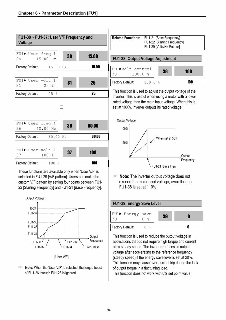
Chapter 6 - Parameter Description [FU1]
94
FU1-30 ~ FU1-37: User V/F Frequency and Voltage
□
□
□
These functions are available only when ‘User V/F’ is
selected in FU1-29 [V/F pattern]. Users can make the
custom V/F pattern by setting four points between FU1-
22 [Starting Frequency] and FU1-21 [Base Frequency].
[User V/F]
☞ Note: When the ‘User V/F’ is selected, the torque boost
of FU1-26 through FU1-28 is ignored.
FU1-38: Output Voltage Adjustment
This function is used to adjust the output voltage of the
inverter. This is useful when using a motor with a lower
rated voltage than the main input voltage. When this is
set at 100%, inverter outputs its rated voltage.
☞ Note: The inverter output voltage does not exceed the main input voltage, even though FU1-38 is set at 110%.
FU1-39: Energy Save Level
This function is used to reduce the output voltage in
applications that do not require high torque and current
at its steady speed. The inverter reduces its output
voltage after accelerating to the reference frequency
(steady speed) if the energy save level is set at 20%.
This function may cause over-current trip due to the lack
of output torque in a fluctuating load.
This function does not work with 0% set point value.
Related Functions: FU1-21 [Base Frequency] FU1-22 [Starting Frequency] FU1-29 [Volts/Hz Pattern]
FU1► User freq 1
30 15.00 Hz 15.00
30
Factory Default: 15.00 Hz 15.00
FU1► User volt 1 31 25 %
25
31
Factory Default: 25 % 25
FU1► User volt 4 37 100 %
100
37
Factory Default: 100 % 100
FU1► User freq 4
36 60.00 Hz 60.00
36
Factory Default: 60.00 Hz 60.00
Output Voltage
Output Frequency
Freq. Base
100%
FU1-31
FU1-30
FU1-34
FU1-33
FU1-35
FU1-37
FU1-36
FU1-32
FU1►Volt control 38 100.0 %
100
38
Factory Default: 100.0 % 100
Output Voltage
Output Frequency
FU1-21 [Base Freq]
100%
50% When set at 50%
FU1► Energy save
39 0 % 0
39
Factory Default: 0 % 0

Chapter 6 - Parameter Description [FU1]
95
[When Energy Save Level is set at 20%]
☞ Note: This function is not recommended for a large load
or for an application that need frequent acceleration and
deceleration.
☞ Note: This function does not work when ‘Sensorless’ is
selected in FU2-40 [Control Mode].
FU1-50: Electronic Thermal (Motor i2t) Selection FU1-51: Electronic Thermal Level for 1 Minute FU1-52: Electronic Thermal Level for Continuous FU1-53: Electronic Thermal Characteristic (Motor type) selection
These functions are to protect the motor from
overheating without using additional thermal overload
relay. Inverter calculates the temperature rising of the
motor using several parameters and determines whether
or not the motor is overheated. Inverter will turn off its
output and display a trip message when the electronic
thermal feature is activated.
This function activates the ETH parameters by setting
‘Yes’.
This is the reference current when the inverter
determines the motor has overheated. It trips in one
minute when 150% of rated motor current established in
FU2-33 flows for one minute.
☞ Note: The set value is the percentage of FU2-33 [Rated
Motor Current].
This is the current at which the motor can run
continuously. Generally, this value is set to ‘100%’ and
which means the rated motor current set in FU2-33. This
value must be set less than FU1-52 [ETH 1min].
☞ Note: The set value is the percentage of FU2-33 [Rated
Motor Current].
[Motor i2t Characteristic Curve]
To make the ETH function (Motor i2t) work correctly, the
motor cooling method must be selected correctly
according to the motor.
[Self-cool] is a motor that has a cooling fan connected
directly to the shaft of the motor. Cooling effects of a
self-cooled motor decrease when a motor is running at
low speeds. The motor current is derated as the motor
speed decreases.
[Forced-cool] is a motor that uses a separate motor to
power a cooling fan. As the motor speed changes, the
cooling effect does not change.
Output Voltage
Output Frequency
Reference Frequency (Steady Speed)
100%
80%
FU1► ETH select 50 --- No ---
0
50
Factory Default: No 0
FU1► ETH 1min
51 180 % 180
51
Factory Default: 180 % 180
FU1► ETH cont 52 120 %
120
52
Factory Default: 120 % 120
Load Current [%]
Trip Time
FU1-51 [ETH 1min]
1 minute
FU1-52 [ETH cont]
FU1► Motor type
53 Self-cool 0
53
Factory Default: Self-cool 0

Chapter 6 - Parameter Description [FU1]
96
[Load Current Derating Curve]
☞ Note: Despite the motor current changing frequently due
to load fluctuation or acceleration and deceleration, the
inverter calculates the i2t and accumulates the value to
protect the motor.
FU1-54: Overload Warning Level FU1-55: Overload Warning Time
The inverter generates an alarm signal when the output
current has reached the FU1-54 [Overload Warning
Level] for the FU1-55 [Overload Warning Time]. The
alarm signal persists for the FU1-55 even if the current
has become the level below the FU1-54.
Multi-function output terminal (AXA-AXC) is used as the
alarm signal output. To output the alarm signal, set I/O
44 [Multifunction Auxiliary Contact Output] to ‘OL’.
☞ Note: Inverter is not tripped by this function.
☞ Note: The set value is the percentage of FU2-33 [Rated
Motor Current].
[Overload Warning]
FU1-56: Overload Trip Selection FU1-57: Overload Trip Level FU1-58: Overload Trip Delay Time
Inverter cuts off its output and displays fault message
when the output current persists over the FU1-57
[Overload Trip Level] for the time of FU1-58 [Overload
Trip Time]. This function protects the inverter and motor
from abnormal load conditions.
100%
95%
65%
Output Current
20Hz 60Hz
Self-Cool
Forced-Cool
Related Functions: FU2-33 [Rated Motor Current]
FU1► OL level 54 150 %
150
54
Factory Default: 150 % 150
FU1► OL time
55 10.0 sec 10.0
55
Factory Default: 10.0 sec 10.0
t1: FU1-55 [Overload Warning Time]
Output Current
Time
Time
FU1-54 [OL Level]
FU1-54 [OL Level]
AXA-AXC ON
t1 t1
Related Functions: FU2-33 [Rated Motor Current] I/O-44 [Multi-function Auxiliary Contact Output]
FU1► OLT select 56 --- Yes ---
1
56
Factory Default: Yes 1
FU1► OLT level 57 180 %
180
57
Factory Default: 180 % 180
FU1► OLT time
58 60.0 sec 60.0
58
Factory Default: 60.0 sec 60.0
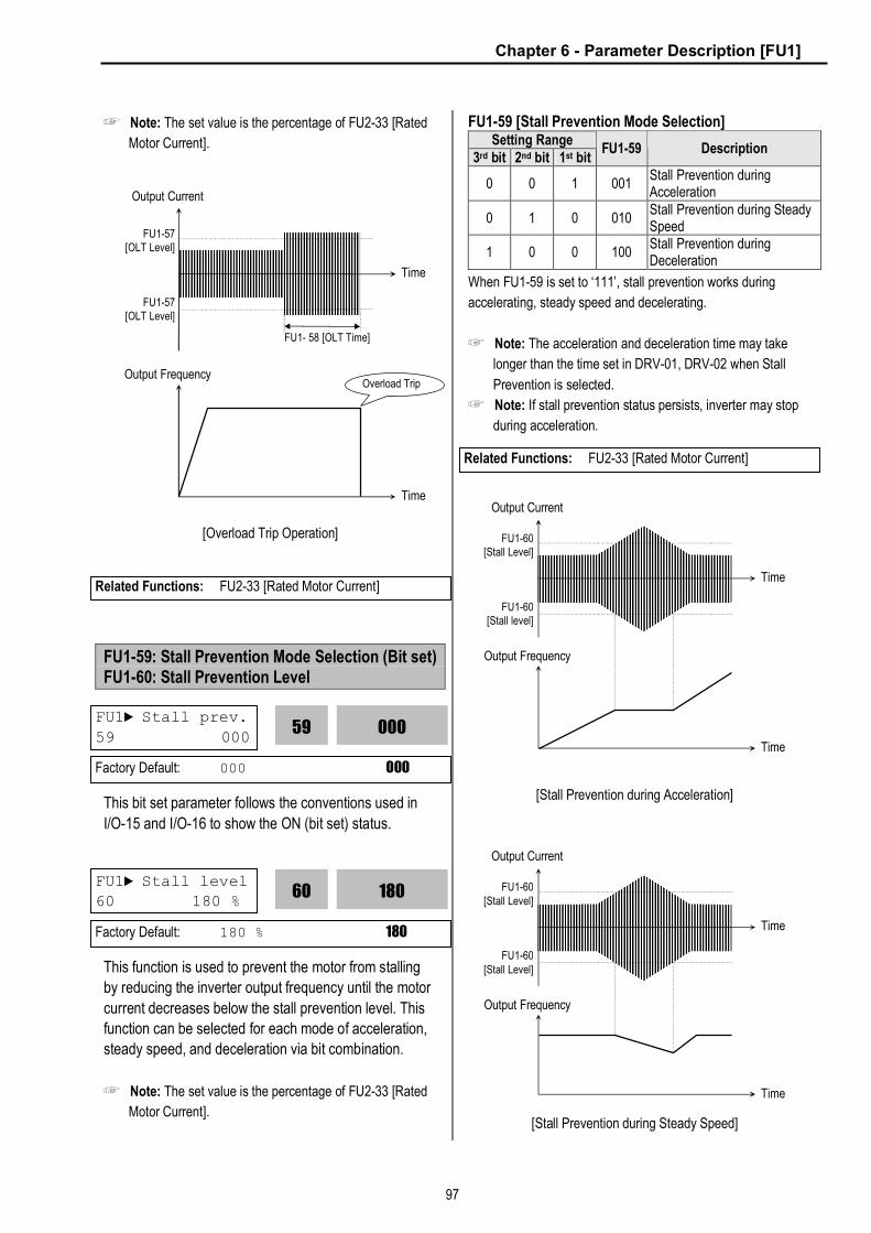
Chapter 6 - Parameter Description [FU1]
97
☞ Note: The set value is the percentage of FU2-33 [Rated
Motor Current].
[Overload Trip Operation]
FU1-59: Stall Prevention Mode Selection (Bit set) FU1-60: Stall Prevention Level
This bit set parameter follows the conventions used in
I/O-15 and I/O-16 to show the ON (bit set) status.
This function is used to prevent the motor from stalling
by reducing the inverter output frequency until the motor
current decreases below the stall prevention level. This
function can be selected for each mode of acceleration,
steady speed, and deceleration via bit combination.
☞ Note: The set value is the percentage of FU2-33 [Rated
Motor Current].
FU1-59 [Stall Prevention Mode Selection] Setting Range
3rd bit 2nd bit 1st bit FU1-59 Description
0 0 1 001 Stall Prevention during Acceleration
0 1 0 010 Stall Prevention during Steady Speed
1 0 0 100 Stall Prevention during Deceleration
When FU1-59 is set to ‘111’, stall prevention works during
accelerating, steady speed and decelerating.
☞ Note: The acceleration and deceleration time may take
longer than the time set in DRV-01, DRV-02 when Stall
Prevention is selected.
☞ Note: If stall prevention status persists, inverter may stop
during acceleration.
[Stall Prevention during Acceleration]
[Stall Prevention during Steady Speed]
Output Current
Time
Time
FU1-57 [OLT Level]
FU1-57 [OLT Level]
Output Frequency
FU1- 58 [OLT Time]
Overload Trip
Related Functions: FU2-33 [Rated Motor Current]
FU1► Stall prev.
59 000 000
59
Factory Default: 000 000
FU1► Stall level 60 180 %
180
60
Factory Default: 180 % 180
Related Functions: FU2-33 [Rated Motor Current]
Output Current
Time
Output Frequency
Time
FU1-60[Stall level]
FU1-60[Stall Level]
Output Current
Time
Output Frequency
Time
FU1-60[Stall Level]
FU1-60[Stall Level]

Chapter 6 - Parameter Description [FU1]
98
[Stall Prevention during Deceleration]
FU1-99: Return Code (7-Segment Keypad)
This code is used to exit a group when using a 7-
segment keypad. After pressing PROG/ENT key, set the
value to ‘1’ and press the PROG/ENT key again to exit.
Time
DC Link Voltage
Time
Output Frequency
390VDC or680V DC
1
99
Factory Default: 1
Related Functions: FU2-99 [Return Code] I/O-99 [Return Code] EXT-99 [Return Code] COM-99 [Return Code]

Chapter 6 - Parameter Description [FU2]
99
6.3 Function 2 Group [FU2]
FU2-00: Jump to desired code #
Jumping directly to any parameter code can be
accomplished by entering the desired code number. This
code is available only with LCD keypad.
FU2-01: Previous Fault History 1 FU2-02: Previous Fault History 2 FU2-03: Previous Fault History 3 FU2-04: Previous Fault History 4 FU2-05: Previous Fault History 5 FU2-06: Erase Fault History
□
□
□
This code displays up to five previous fault (trip) status of the inverter. Use the PROG, ▲ and ▼ key before
pressing the RESET key to check the fault content(s),
output frequency, output current, and whether the
inverter was accelerating, decelerating, or in constant speed at the time of the fault occurred. Press the ENT
key to exit. The fault content will be stored in FU2-01 through FU2-05 when the RESET key is pressed. For
more detail, please refer to Chapter 7.
[Fault Contents] Keypad Display
Fault (Trip) LCD 7-Segment
Over-Current 1 Over Current 1 OC
Over-Voltage Over Voltage OV
External Trip Input A External-A EXTA
Emergency Stop (Not Latched)
BX BX
Low-Voltage Low Voltage LV
Fuse Open Fuse Open FUSE
Ground Fault Ground Fault GF
Over-Heat on Heat sink Over Heat OH
Electronic Thermal Trip E-Thermal ETH
Over-Load Trip Over Load OLT
Inverter H/W Fault - EEP Error - ADC Offset - WDOG Error - In-Phase Open
HW-Diag HW
External Trip Input B External-B EXTB
Over-Current 2 Arm Short ASHT
Option Error Option OPT
Output Phase Loss Phase Open PO
Inverter Over-Load Inv. OLT IOLT
☞ Note: There are WDOG error, EEP error, and ADC
Offset for the inverter Hardware Fault, and the inverter
will not reset when H/W fault occurs. Repair the fault
before turning on the power.
☞ Note: When multiple faults occur, only the highest-level
fault will be displayed.
This function erases all fault histories of FU2-01 to FU-
05 from the memory.
FU2► Jump code 00 1
Factory Default: 1
Related Functions: DRV-12 [Fault Display] displays current fault status.
FU2► Last trip-1 01 None
0
01
Factory Default: None 0
FU2► Last trip-5
05 None 0
05
Factory Default: None 0
FU2► Erase trips
06 --- No ---
0
06
Factory Default: No 0
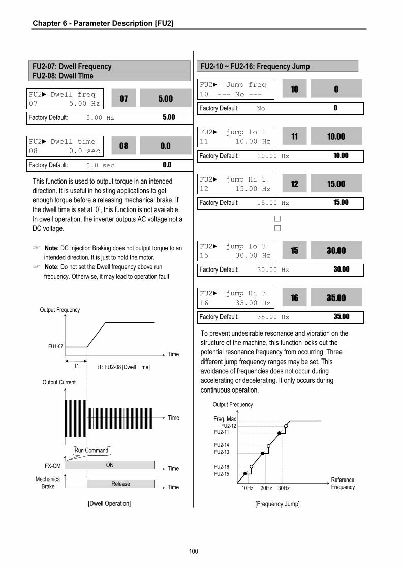
Chapter 6 - Parameter Description [FU2]
100
FU2-07: Dwell Frequency FU2-08: Dwell Time
This function is used to output torque in an intended
direction. It is useful in hoisting applications to get
enough torque before a releasing mechanical brake. If
the dwell time is set at ‘0’, this function is not available.
In dwell operation, the inverter outputs AC voltage not a
DC voltage.
☞ Note: DC Injection Braking does not output torque to an
intended direction. It is just to hold the motor.
☞ Note: Do not set the Dwell frequency above run
frequency. Otherwise, it may lead to operation fault.
[Dwell Operation]
FU2-10 ~ FU2-16: Frequency Jump
□
□
To prevent undesirable resonance and vibration on the
structure of the machine, this function locks out the
potential resonance frequency from occurring. Three
different jump frequency ranges may be set. This
avoidance of frequencies does not occur during
accelerating or decelerating. It only occurs during
continuous operation.
[Frequency Jump]
FU2► Dwell freq 07 5.00 Hz
5.00
07
Factory Default: 5.00 Hz 5.00
FU2► Dwell time 08 0.0 sec
0.0
08
Factory Default: 0.0 sec 0.0
FX-CM ON
Output Frequency
Time
Time
Run Command
FU1-07
t1 t1: FU2-08 [Dwell Time]
Output Current
Time
Mechanical Brake Release
Time
FU2► Jump freq 10 --- No ---
0
10
Factory Default: No 0
Output Frequency
Freq. Max
Reference Frequency 10Hz 20Hz 30Hz
FU2-12 FU2-11
FU2-14 FU2-13
FU2-16
FU2-15
FU2► jump lo 1
11 10.00 Hz 10.00
11
Factory Default: 10.00 Hz 10.00
FU2► jump Hi 1 12 15.00 Hz
15.00
12
Factory Default: 15.00 Hz 15.00
FU2► jump lo 3 15 30.00 Hz
30.00
15
Factory Default: 30.00 Hz 30.00
FU2► jump Hi 3
16 35.00 Hz 35.00
16
Factory Default: 35.00 Hz 35.00

Chapter 6 - Parameter Description [FU2]
101
☞ Note: When the reference frequency is set inside the jump
frequency, the output frequency goes to the frequency
marked by “n” symbol.
☞ Note: If one frequency jump range is required, set all
ranges to the same range.
FU2-17: Start Curve for S-Curve Accel/Decel Pattern FU2-18: End Curve for S-Curve Accel/Decel Pattern
This parameter is used to adjust the Accel and Decel
pattern when ‘S-Curve’ is selected in FU1-05 and FU1-
06 respectively. To use this function, the Reference
Frequency for Accel and Decel set in FU2-70 should be
set to ‘Delta freq’.
[S-Curve Adjustment]
Actual Accel Time = DRV-01 + (DRV-01 * FU2-17)/2 +
(DRV-01*FU2-18)/2
Actual Decel Time = DRV-02 + (DRV-02 * FU2-17)/2 +
(DRV-02*FU2-18)/2
Ex) If DRV-10: 1 sec, FU2-17: 40%, FU2-18: 20%,
Actual Accel Time = 1 sec + (1sec*0.4)/2 + (1sec*0.2)/2
= 1.3 sec
FU2-19: Input/Output Phase Loss Protection (Bit Set)
This function is used to cut the inverter output off in case
of phase loss in either input power or inverter output.
FU2-19 [Phase Loss Protection Select] Setting Range 2nd bit 1st bit
FU2-19 Description
0 0 00 Phase loss protection does not work 0 1 01 Protect inverter from output phase loss 1 0 10 Protect inverter from input phase loss
1 1 11 Protect inverter from input and output phase loss
FU2-20: Power ON Start Selection
If FUN-20 is set to ‘No’, restart the inverter by cycling the
FX or RX terminal to CM terminal after power has been
restored.
If FUN-20 is set to ‘Yes’, the inverter will restart after
power is restored. If the motor is rotating by inertia at the
time power is restored, the inverter may trip. To avoid
this trip, use ‘Speed Search’ function by setting FU2-22
to ‘1xxx’.
FU2► Trip select 19 00
00
19
Factory Default: 00 00
FU2►Power-on run 20 --- No ---
0
20
Factory Default: No 0
Related Functions: FU2-22 to FU2-25 [Speed Search]
FU2► Start Curve 17 40 %
40
17
Factory Default: 40% 40
FU2► End Curve
18 40 % 40
18
Factory Default: 40% 40
Output Frequency
Time
Max. Freq./2
FU2-17 FU2-18 FU2-17 FU2-18
Linear Linear

Chapter 6 - Parameter Description [FU2]
102
[Power ON Start: ‘No’]
[Power ON Start: ‘Yes’]
☞ Note: In case of using ‘Power ON Start’ to ‘Yes’, make
sure to utilize appropriate warning notices to minimize the
potential for injury or equipment damage.
FU2-21: Restart After Fault Reset
If FU2-21 is set to ‘Yes’, inverter will restart after the
RST (reset) terminal has been reset a fault.
If FU2-21 is set to ‘No’, restart the inverter by cycling the
FX or RX terminal to CM terminal after the fault has
been reset. If the motor is rotating by inertia at the time
power is restored, the inverter may trip. To avoid this trip,
use ‘Speed Search’ function by setting FU2-22 to ‘xx1x’.
[Reset restart: ‘No’]
[Reset restart: ‘Yes’]
☞ Note: In case of using ‘Reset Restart’ to ‘Yes’, make sure
to utilize appropriate warning notices to minimize the
potential for injury or equipment damage.
FU2-22: Speed Search Selection (Bit Set) FU2-23: Current Limit Level During Speed Search FU2-24: P Gain During Speed Search FU2-25: I Gain During Speed Search
Input Power
Time
FX-CM ON Time
ON
No Effect Start
Power On
Output Frequency
Time
Input Power
Time
FX-CM ON Time
Start
Power On
Output Frequency
Time
FU2► RST restart
21 --- No --- 0
21
Factory Default: No 0
Output Frequency
Time
FX-CM ON Time
RST-CM ON Time
ON
No Effect Start
Tripped
Output Frequency
Time
FX-CM ON Time
RST-CM ON Time
Start
Tripped
Related Functions: FU2-22 ~ FU2-25 [Speed Search]
Related Functions: FU2-22 ~ FU2-25 [Speed Search]
FU2►Speed Search 22 0000
0000
22
Factory Default: 0000 0000
FU2► SS Sup-Curr
23 150 % 150
23
Factory Default: 150 % 150

Chapter 6 - Parameter Description [FU2]
103
This function is used to permit automatic restarting after
Power ON, Fault Reset, and Instant Power Failure
without waiting for the motor to stop.
The speed search gain should be set after considering
the inertia moment (GD2) and magnitude of torque of the
load. FU2-37 [Load Inertia] must be set at the correct
value to make this function operate correctly.
FU2-22 [Speed Search Select] Setting Range
4th bit 3rd bit 2nd bit 1st bit Description
0 0 0 0 Speed search function does not work 0 0 0 1 Speed search during Accelerating
0 0 1 0 Speed search during a Fault Reset restarting (FU2-21) and Auto restarting (FU2-26)
0 1 0 0 Speed search during Instant Power Failure restarting.
1 0 0 0 Speed search during Power ON starting (FU2-20)
When FU2-22 is set to ‘1111’, Speed Search works for all
conditions.
FU2-22 [Speed Search Selection] selects the speed
search function.
FU2-23 [Current Limit Level] is the current that the
inverter limits its current rise during speed searching.
(The set value is the percentage of FU2-33 [Rated Motor
Current])
FU2-24 [P Gain] is the proportional gain used for speed
search. Set this value according to load inertia set in
FU2-37.
FU2-25 [I Gain] is the Integral gain used for speed
search. Set this value according to load inertia set in
FU2-37.
[Speed Search Operation]
FU2-26: Number of Auto Restart Attempt FU2-27: Delay Time Before Auto Restart
This function is used to allow the inverter to reset itself
for a selected number of times after a fault has occurred.
The inverter can restart itself automatically when a fault
occurs. To use the speed search function during auto
restarting set FU2-22 to ‘xx1x’. See FU2-22 ~ FU2-25.
When an under voltage (LV) fault, inverter disable (BX)
Input Power
Time
Motor Speed
Time
Output Frequency
Output Voltage
Time
Time
Input Power loss
FU2► SS P-gain
24 100 100
24
Factory Default: 100 100
FU2► SS I-gain 25 200
200
25
Factory Default: 200 200
FU2►Retry number
26 0 0
26
Factory Default: 0 0
FU2►Retry delay 27 1.0 sec
1.0
27
Factory Default: 1.0 sec 1.0
Related Functions: FU2-20 [Power ON Start] FU2-21 [Restart after Fault Reset] FU2-26 ~ FU2-27 [Auto Restart] FU2-30 ~ FU2-37 [Motor Parameters]
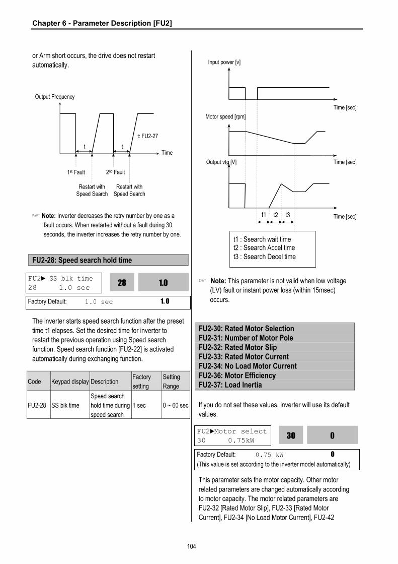
Chapter 6 - Parameter Description [FU2]
104
or Arm short occurs, the drive does not restart
automatically.
☞ Note: Inverter decreases the retry number by one as a
fault occurs. When restarted without a fault during 30
seconds, the inverter increases the retry number by one.
FU2-28: Speed search hold time
The inverter starts speed search function after the preset
time t1 elapses. Set the desired time for inverter to
restart the previous operation using Speed search
function. Speed search function [FU2-22] is activated
automatically during exchanging function.
Code Keypad display Description Factory
setting
Setting
Range
FU2-28 SS blk time
Speed search
hold time during
speed search
1 sec 0 ~ 60 sec
☞ Note: This parameter is not valid when low voltage
(LV) fault or instant power loss (within 15msec)
occurs.
FU2-30: Rated Motor Selection FU2-31: Number of Motor Pole FU2-32: Rated Motor Slip FU2-33: Rated Motor Current FU2-34: No Load Motor Current FU2-36: Motor Efficiency FU2-37: Load Inertia
If you do not set these values, inverter will use its default
values.
This parameter sets the motor capacity. Other motor
related parameters are changed automatically according
to motor capacity. The motor related parameters are
FU2-32 [Rated Motor Slip], FU2-33 [Rated Motor
Current], FU2-34 [No Load Motor Current], FU2-42
Output Frequency
Time
1st Fault 2nd Fault
Restart with Speed Search
Restart with Speed Search
t t
t: FU2-27
Input power [v]
Time [sec]
Motor speed [rpm]
t1 t2 t3
t1 : Ssearch wait time t2 : Ssearch Accel time t3 : Ssearch Decel time
Output vtg [V]
Time [sec]
Time [sec]
FU2►Motor select 30 0.75kW
0
30
Factory Default: 0.75 kW 0
(This value is set according to the inverter model automatically)
FU2► SS blk time 28 1.0 sec
1.0
28
Factory Default: 1.0 sec 1. 0

Chapter 6 - Parameter Description [FU2]
105
[Stator Resistance], FU2-43 [Rotor Resistance], and
FU2-44 [Leakage Inductance].
If you know the motor parameters, set the values in the
relevant codes for better control performance.
This is used to display the motor speed. If you set this
value to 2, inverter will display 3600 rpm instead
1800rpm at 60Hz output frequency. (See motor
nameplate)
This is used in ‘Slip Compensation’ control. If you set
this value incorrectly, motor may stall during slip
compensation control. (See motor nameplate)
This is very importance parameter that must be set
correctly. This value is referenced in many other inverter
parameters. (See motor nameplate)
This parameter is only displayed when ‘Slip Compen’ is
selected in FU2-40 [Control Method].
This function is used to maintain constant motor speed.
To keep the motor speed constant, the output frequency
varies within the limit of slip frequency set in FU2-32
according to the load current. For example, when the
motor speed decreases below the reference speed
(frequency) due to a heavy load, the inverter increases
the output frequency higher than the reference
frequency to increase the motor speed. The inverter
increases or decreases the output by delta frequency
shown below.
Output frequency = Reference freq. + Delta freq.
This value is used for calculating the output wattage
when FU2-72 is set to ‘Watt’.
This parameter is used for sensorless control, minimum
Accel/Decel, optimum Accel/Decel and speed search.
For better control performance, this value must be set as
exact as possible.
Set ‘0’ for loads that has load inertia less than 10 times
that of motor inertia.
Set ‘1’ for loads that have load inertia about 10 times that of motor inertia.
FU2► Pole number 31 4
Factory Default: 4 4
FU2► Rated-Slip 32 3.00 Hz
Factory Default: 3.00 Hz 3.00
FU2► Rated-Curr 33 3.6 A
3.6
33
Factory Default: 3.6 A 3.6 (This value is set according to the motor capacity set in FU2-30)
FU2► Noload-Curr 34 1.8 A
1.8
34
Factory Default: 1.8 A 1.8
(This value is set according to the motor capacity set in FU2-30)
Delta Freq.
= Output current – No load current
Rated current – No load current Rated Slip ×
3.00
32
4
31
FU2► Efficiency 36 72 %
72
36
Factory Default: 72% 72
(This value is set according to the motor capacity set in FU2-30)
FU2►Inertia rate 37 0
0
37
Factory Default: 0 0
FU2► Motor Volt 35 %
-
35
Factory Default: % -
(This value is set according to the motor capacity set in FU2-30)

Chapter 6 - Parameter Description [FU2]
106
FU2-38: Carrier Frequency
Code LCD
Display Description Setting Setting range
FU2-
38 Carrier freq
Carrier
Frequency 5 [kHz] 1 ~ 15 [kHz]
This parameter affects the audible sound of the motor,
noise emission from the inverter, inverter termperature,
and leakage current. If the ambient temperature where
the inverter is installed is high or other equipment may
be affected by potential inverter noise, set this value
lower. If set above 10kHz, use it by reducing 5%[1kHz]
of the rated current. Setting Carrier freqeuncy set below
2.5[kHz] when the FU2-39 [Control mode selection] is
set to Vector_SPD, Vector_TRQ could weaken the
control performance.
Note) Max carrier frequency for inverters above
40HP(30kW) are indicated as below;
200V 400V
30/37kW (40/50HP) 10kHz 10kHz
45/55kW (60/75HP) 8kHz 8kHz
75kW (100HP) - 7kHz
Max carrier frequency for DB integrated models
(11~22kW/15~30HP) is 10kHz.
FU2-39: Control mode selection
l Selects the control mode of the inverter
FU2-40 setting
LCD Display Description
0 V/F V/F Control 1 Slip compen Slip compensation
2 Sensorless_S Sensorless vector control speed operation
3 Sensorless_T Sensorless vector control torque operation
4 Vector_SPD Vector control speed operation
5 Vector_TRQ Vector control torque operation
☞ Note: Setting Vector_SPD, Vector_TRQ is only valid
when the inverter is equipped with SUB-B board and
EXT-12 [F mode] is set to Feed-back. Vector control
comprises of Vector_SPD, Vector_TRQ with
Sensorless_S and Sensorless_T.
l V/F control:
This parameter controls the voltage/frequency ratio
constant. It is recommended to use the torque boost
function when a greater starting torque is required.
Related function: FU1-26~28 [Torque boost] l Slip compensation:
This function is used to maintain constant motor speed.
To keep the motor speed constant, the output frequency
varies within the limit of slip frequency set in FU2-32
according to the load current. For example, when the
motor speed decreases below the reference speed
(frequency) due to a heavy load, the inverter increases
the output frequency higher than the reference
frequency to increase the motor speed. The inverter
increases or decreases the output by delta frequency
shown below.
Delta freq = Rated slip * (Output current - Motor No load current) / rated current - Motor No load current)
Output freq = Reference freq + Delta freq
☞ Note: Motor parameters must be set correctly for
optimal performance of control.
FU2-32~36 [Motor related parameters] is automatically
determined by FU2-30 [Rated Motor selection]. Most
suitable motor capacity corresponding inverter capacity
is set as factory setting, but the following setting value
can be adjusted if necessary.
Related parameter: FU2-30~37 [Motor related
parameters]
Code LCD Display Description FU2-30 Motor select Select motor capacity FU2-32 Rated-Slip Motor rated slip (Hz)
FU2-33 Rated-Curr Motor rated current (rms) FU2-34 Noload-Curr Motor no load current (rms) FU2-36 Efficiency Motor efficiency (%) FU2-37 Inertia rate Motor inertia rate
FU2►Carrier freq
38 5 kHz 5
38
Factory Default: 5 kHz 5
FU2►Control mode 39 V/F
0
39
Factory Default: V/F 0

Chapter 6 - Parameter Description [FU2]
107
l Sensorless_S (Sensorless vector speed control) Vector_SPD (Vector control speed) operation:
Use it when 1) high starting torque needed at low speed
2) load fluctuation is high 3) rapid response needed. To
activate this function, set FU2-30~37 and FU2-39
properly.
If not using LG 220V/440V Class motor: Set Yes in FU2-
40 [Auto tuning] first.
Vector_SPD control is Only valid when Sub-B board is
mounted (Speed-detecting Encoder installed to the
motor).
Conditions for Sensorless Vector Control
Conditions for sensorless control are as follows. If one of
the following conditions is not satisfied, the inverter may
malfunction with insufficient torque, irregular rotation, or
excessive motor noise. It is recommended to use V/F
control.
¨ Use a motor capacity that is equal to or one
horsepower lower than the inverter capacity.
¨ Two different kinds of motor parameters can be set
for one inverter, but use only one motor parameter
in Sensorless control mode.
¨ If the motor in use is not LG 220V/440V Class
motor or using 220V/380V dual use motor, utilize
the auto tuning feature in FU2-40 [Auto tuning]
before starting.
¨ Set appropriate values for the electronic thermal
function, the overload limit function and the stall
prevention. The set values should exceed 150% of
the rated motor current.
¨ When DRV–04 [Frequency Mode] is set to “V1”, “I”,
or “V1+I”, eliminate any potential noise influence
with the frequency reference.
¨ The number of the motor pole should be 2 pole, 4
pole, or 6 pole.
¨ The distance between the inverter and the motor
should not exceed 100m (328 ft).
Precautions When Using Sensorless Vector Control
¨ Forced-cooling should be used for the motor when
the average operating speed is under 20Hz and
more than 100% load is used constantly.
¨ The motor may rotate 0.5% faster than the
maximum speed if the motor temperature does not
reach normal operating temperature.
¨ Installing the DB (Dynamic Brake) braking unit
option can improve the performance during
regeneration for systems with frequent acceleration
and deceleration operations.
¨ Utilize the auto-tuning feature when the motor
reaches normal temperature (average temperature
where the motor normally operates).
¨ Output torque may be reduced when an output filter
option is used between the inverter and the motor.
¨ If the speed is unstable when the FU2–38 [Carrier
Frequency Selection] is set to a value more than
10kHz, change the setting to 5~10kHz.
¨ Over current fault can occur if the FU2-41 [Stator
Resistance (Rs)] is set to a value more than twice
the auto tuned value
¨ Max setting range is 300 Hz.
Detail Tuning Method for Sensorless Vector Control
¨ Adjust the FU2–34 [No Load Motor Current (RMS)]
value larger or smaller by 5% units if the current is
larger or smaller than that of V/F control with small
load.
¨ Adjust the FU2–32 [Rated Motor Slip] value larger
or smaller by 5% units if the speed is faster or
slower than that of V/F control with small load.
l Sensorless_T(Sensorless Vector Torque) Operation: All settings are the same as Sensorless_S except using torque reference for torque control.
l Vector_TRQ (Vector control torque) Operation: All settings are the same as Vector_SPD except using torque reference for torque control.
Related Functions: FU2-30~37 [Motor related parameters] FU2-41~44 [Motor constant] FU2-45~46 [P/I gain for Sensorless] EXT-25~26 [P/I gain for Vector_SPD], EXT-27~28 [Torque limit for Vector_SPD]
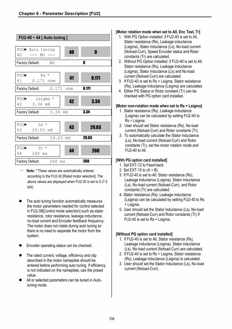
Chapter 6 - Parameter Description [FU2]
108
FU2-40 ~ 44 [ Auto tuning ]
☞ Note: * These values are automatically entered
according to the FU2-30 [Rated motor selection]. The
above values are displayed when FU2-30 is set to 5 (7.5
kW).
l The auto tuning function automatically measures the motor parameters needed for control selected in FU2-39[Control mode selection] such as stator resistance, rotor resistance, leakage inductance, no-load current and Encoder feedback frequency. The motor does not rotate during auto tuning so there is no need to separate the motor from the system.
l Encoder operating status can be checked. l The rated current, voltage, efficiency and slip
described in the motor nameplate should be entered before performing auto tuning. If efficiency is not indicated on the nameplate, use the preset value.
l All or selected parameters can be tuned in Auto-tuning mode.
[Motor rotation mode when set to All, Enc Test, Tr] 1. With PG Option installed: if FU2-40 is set to All,
Stator resistance (Rs), Leakage inductance (Lsigma), Stator inductance (Ls), No-load current (Noload-Curr), Speed Encoder status and Rotor constants (Tr) are calculated.
2. Without PG Option installed: if FU2-40 is set to All, Stator resistance (Rs), Leakage inductance (Lsigma), Stator inductance (Ls) and No-load current (Noload-Curr) are calculated.
3. If FU2-40 is set to Rs + Lsigma, Stator resistance (Rs), Leakage inductance (Lsigma) are calculated.
4. Either PG Status or Rotor constant (Tr) can be checked with PG option card installed.
[Motor non-rotation mode when set to Rs + Lsigma]
1. Stator resistance (Rs), Leakage inductance (Lsigma) can be calculated by setting FU2-40 to Rs + Lsigma.
2. User should set Stator resistance (Rs), No-load current (Noload-Curr) and Rotor constants (Tr).
3. To automatically calculate the Stator inductance (Ls), No-load current (Noload-Curr) and Rotor constants (Tr), set the motor rotation mode and FU2-40 to All.
[With PG option card installed]
1. Set EXT-12 to Feed-back. 2. Set EXT-15 to (A + B). 3. If FU2-40 is set to All, Stator resistance (Rs),
Leakage inductance (Lsigma), Stator inductance (Ls), No-load current (Noload-Curr), and Rotor constants (Tr) are calculated.
4. Stator resistance (Rs), Leakage inductance (Lsigma) can be calculated by setting FU2-40 to Rs + Lsigma.
5. User should set the Stator inductance (Ls), No-load current (Noload-Curr) and Rotor constants (Tr) if FU2-40 is set to Rs + Lsigma.
[Without PG option card installed]
1. If FU2-40 is set to All, Stator resistance (Rs), Leakage inductance (Lsigma), Stator inductance (Ls), No-load current (Noload-Curr) are calculated.
2. If FU2-40 is set to Rs + Lsigma, Stator resistance (Rs), Leakage inductance (Lsigma) is calculated.
3. User should set the Stator inductance (Ls), No-load current (Noload-Curr).
FU2► Auto tuning
40 --- NO --- 0
40
Factory Default: NO 0
FU2► Rs *
41 0.171 ohm 0.171
41
Factory Default: 0.171 ohm 0.171
FU2► Ls *
43 29.03 mH 29.03
43
Factory Default: 29.03 mH 29.03
FU2► Tr *
44 260 ms 260
44
Factory Default: 260 ms 260
FU2► Lsigma *
42 3.34 mH 3.34
42
Factory Default: 3.34 mH 3.34

Chapter 6 - Parameter Description [FU2]
109
FU2-40 LCD display Description 0 No Auto-tuning disabled
1 All Auto-tuning all
parameters
2 Rs + Lsigma Stator resistance (Rs)
and Leakage inductance (Lsigma) Auto-tuning
3 Enc Test PG status check
4 Tr Rotor constant(Tr)
calculation
☞ Note 1: Ls and Noload-Curr are only valid during Motor Rotation mode.
☞ Note 2: The motor constants values change with temperature change, so auto tuning is to be conducted after the temperature of the motor is stabilized.
☞ Note 3: The auto-tuning result could be different unless LG motor is used.
☞ Note 4: The actual motor parameters (Rs, Rr, Lsigma, Tr) can be used or set by user.
Code LCD display Name Description
FU2-34
Noload-Curr
No Load Motor
Current (RMS)
Setting and display the No Load Motor Current
(RMS)
FU2-40
Auto tuning Auto Tuning Auto-tuning enable
FU2-41
Rs Stator
resistance Setting and display the Stator resistance Rs
FU2-42
Lsigma Leakage
inductance Setting and display the
Lsigma FU2-43
Ls Stator
inductance Setting and display the Stator inductance Ls
FU2-44
Tr Rotor
constant Setting and display the
Rotor constant Tr. [Keypad display during Auto-tuning of motor parameters]
Display Code
LED 7-Seg. Description
Rs Tuning T1 Displayed during Stator
resistance (Rs) Auto-tuning
Lsigma Tuning
T2 Displayed during Leakage inductance (Lsigma) auto-tuning.
Ls Tuning T3 Displayed during Stator
inductance (Ls) and No-load current auto-tuning.
ENC Test T4 Displayed during Encoder auto-
tuning.
FU2-40
Tr Tuning T5 Displayed during Rotor filter
time constant (Tr) auto-tuning
[Keypad error display after Encoder test]
Display Code
LED 7-Segment Description
Enc Err T6 Displayed when incorrect
Encoder wiring error occurs FU2-40
Enc Rev T7 Displayed when Encoder
wiring is connected reversly. [Motor parameter display corresponding to inverter capacity]
Motor parameter Class
inverter capacity Rs Lsigma Ls Tr
0.8[kW] ~ 5.5[kW]
X.XXX ohm
X.XX mH
X.XX mH
XXX ms
200V 7.5[kW] ~ 55[kW]
X.X mohm
X.XXX mH
X.XX mH
XXX ms
0.8[kW] ~ 1.5[kW]
X.XX ohm
X.X mH X. mH XXX ms
2.2[kW] ~ 15[kW] X.XXX ohm
X.XX mH
X.X mH XXX ms
400V
18.5[kW] ~ 75[kW]
X.X mohm
X.XXX mH
X.XX XXX ms
☞ Note: For 7-segment Keypad, parameter unit is not displayed.
FU2-45: P Gain for Sensorless Control FU2-46: I Gain for Sensorless Control
SL P-gain is the proportional gain of speed controller. If
this value is set high, you can get fast speed response
characteristic. However, if this value is set too high, the
steady state characteristics may become unstable.
SL I-gain is the integral gain of speed controller. If this
value is set low, you can get better transient response
characteristic and steady state characteristic. However,
if this value is set too low, there may be an overshoot in
speed control.
FU2► SL P-gain 45 1000
1000
45
Factory Default: 1000 1000
FU2► SL I-gain 46 100
100
46
Factory Default: 100 100
Related Functions: FU2-30~37 [Motor related parameters] FU2-39 [Control mode selection] EXT-01 [Sub Board Type Display] EXT-14 [Encoder Feedback Frequency] EXT-15 [Pulse Input Signal Selection]

Chapter 6 - Parameter Description [FU2]
110
☞ Note: The response time of a system is affected by the
load inertia. For better control performance, set the FU2-
37 [Load Inertia] correctly.
FU2-47: PID Operation Selection
This code selects the PID control.
For HVAC or Pump applications, the PID control can be
used to adjust the actual output by comparing a
feedback with a ‘Set-point’ given to the inverter. This
‘Set-point’ can be in the form of Speed, Temperature,
Pressure, Flow level, etc. The ‘Set-point’ and the
feedback signals are provided externally to the inverter
analog input terminals V1, V2 or I. The inverter
compares the signals in calculating ‘total-error’ which is
reflected in the inverter output.
Please see FU2-50 to FU2-54 for more detail.
☞ Note: PID control can be bypassed to manual operation
temporarily by defining one of the multifunction input
terminals (P1~P3) to “Open-loop”. The inverter will
change to manual operation from PID control when this
terminal is ON, and change back to PID control when this
terminal is OFF.
FU2-48: PID F Gain FU2-49: PID Reference Mode Selection FU2-50: PID Output Direction Selection
This code sets F Gain value for use of Feed Forward
control.
When it is set to 100%, the responsiveness (%) of output
F gain value from controller reference value is 100%.
Used when fast response is needed.
Caution) Control System output may become unstable if
this value is set too high.
This code selects reference input for PID control.
This code selects the direction of output value of PID
controller. The output value is added to Target frequency.
FU2-51: PID Feedback Signal Selection FU2-52: P Gain for PID Control FU2-53: I Time for PID Control FU2-54: D Time for PID Control FU2-55: High Limit Frequency for PID Control FU2-56: Low Limit Frequency for PID Control
Select the feedback signal for PID control. This can be
set one of ‘I’ (4-20mA), ‘V1’, ‘V2’ according to the signal
(current or voltage) and the terminal (V1 (0-10V) or V2
(Sub-B board)). Refer to I/O 6-10 for I, I/O1-5 for V1 and
EXT-5-10 [V2 Analog Ref. Freq setting] for V2.
Set the proportional gain for PID control. When P-Gain is
set at 100% and I-Time at 0.0 second, it means the PID
controller output is 100% for 100% error value. P-Gain is
set to 50% and I- Time to 0.0 sec, PID controller output
becomes 50% for 100% error value.
Related Functions: FU2-30 ~ FU2-37 [Motor Parameters] FU2-40 [Control Method]
FU2►Proc PI mode
47 --- No --- 0
47
Factory Default: No 0
Related Functions: DRV-04 [Frequency Mode] I/O-01 to I/O-10 [Analog Signal Setting] I/O-12 to I/O-14 [Multi-Function Input] EXT-15 to EXT-21 [Pulse Input Setting] FU2-50 to FU2-54 [PID Feedback]
FU2► PID F/B
51 I 0
51
Factory Default: I 0
FU2► PID P-gain 52 1.0 % 1.0
52
Factory Default: 1.0 % 1.0
FU2► PID I-time 53 10.0 sec
10.0
53
Factory Default: 10.0 sec 10.0
FU2► PID F-Gain 48 0.0 %
0.0
48
Factory Default: 0.0% 0.0
FU2►Aux Ref Mode 49 None
0
49
Factory Default: None 0
FU2► PID Out Dir 50 Target Freq.
0
50
Factory Default: Target Freq. 0

Chapter 6 - Parameter Description [FU2]
111
Set the integral gain for PID control. This is the time the
PID controller takes to output 100% for 100% error value.
Set the differential gain for PID control.
This is the frequency upper limit at which the output
frequency is limited during PID control.
This is the frequency lower limit at which the output
frequency is limited during PID control.
FU2-57: PID Output Inversion FU2-58: PID Output Scale FU2-59: PID P2 Gain FU2-60: P Gain Scale
This code is used to invert PID controller output.
This code sets the scale of PID controller output.
This code sets the second P-Gain for PID control.
This code sets the scale of P-Gain and P2-Gain. (FU2-
52, FU2-59)
l PID output value can be set to ‘0’ by setting a multi-
function input terminal (P1 ~ P6) to ‘Open loop’ in
I/O-12 ~ I/O-14 or EXT-02 ~ EXT-04.
l The accumulated value by I-Gain can be set to ‘0’
by setting a multi-function input terminal (P1 ~ P6) to
‘iTerm Clear’ in I/O-12 ~ I/O-14 or EXT-02 ~ EXT-04.
l The second P-Gain can be selected for PID
controller by setting a multi-function input (I/O-12 ~
I/O14 or EXT-02 ~ EXT-04) to ‘Open-loop’.
[P Control] This is to compensate the error of a system
proportionally. This is used to make the controller
response fast for an error. When P control is used alone,
the system is easily affected by an external disturbance
during steady state.
[I Control] This is to compensate the error of a system
integrally. This is used to compensate the steady state
error by accumulating them. Using this control alone
makes the system unstable.
[PI control] This control is stable in many systems. If “D
control” is added, it becomes the 3rd order system. In
some systems this may lead to system instability.
[D Control] Since the D control uses the variation ratio
of error, it has the merit of controlling the error before the
error is too large. The D control requires a large control
quantity at start, but has the tendency of increasing the
stability of the system. This control does not affect the
steady state error directly, but increases the system gain
because it has an attenuation effect on the system. As a
result, the differential control component has an effect on
decreasing the steady state error. Since the D control
operates on the error signal, it cannot be used alone.
Always use it with the P control or PI control.
FU2► PID D-time 54 0.0 ms
0.0
54
Factory Default: 0.0 ms 0.0
FU2► PID limit-H 55 60.00 Hz
60.00
55
Factory Default: 60.00 Hz 60.00
Related Functions: DRV-04 [Frequency Mode] FU2-40 [Control Method] I/O-01 ~ I/O-10 [Analog Signal Scaling] EXT-15 ~ EXT-21 [Pulse Input Signals]
FU2► PID limit-L
56 0.00 Hz 0.00
56
Factory Default: 0.00 Hz 0.00
FU2► PID Out Inv.
57 --- No --- 0
57
Factory Default: No 0
FU2►PID Out Scale
58 100.0 % 100.0
58
Factory Default: 100.0 % 100.0
FU2► PID P2-gain
59 100.0 % 100.0
59
Factory Default: 100.0 % 100.0
FU2►P-gain Scale
60 100.0 % 100.0
60
Factory Default: 100.0 % 100.0

Chapter 5 - Parameter Description [FU2]
112
PID Control Block Diagram
Process PID Control Setting
FreqMode
PID FBKselect
Accel/Decel
FU2-49
Aux Ref Mode FU2-51
wTarFreq
SamplingTime
(10msec)
V1
I
V2
DRV-15
PID REFDisplay
DRV-15
PID FBKDisplay
DRV-14
FU2-47
proc PI mode
PID
Kf
Limit
FU2-55
PID upper limitfrequency
proc PI dis
FU2-61
PIDBand Con
FU2-58
Gain
FU2-56
PID Low LimitFrequency
EXT- 2~4
I/O-12~14
Multi-functioninput terminal
(P1~P6) setting
PID outputdirection:(Target)
FU2-50
PID GainOutput
PID F Gain: FeedForward
DRV-04
PID Refsetting
Keypad-1
Keypad-2
V1I
V2
FU2-49
Keypad-1
Keypad-2
V1
I
V2
0
Aux Ref Mode
1, 23, 4, 5
Freq
FU2-62
PID Band
When PID error > PIDBand freq. & during
Acceleration
FU2-52
FU2-53
FU2-54
PID P Gain
PID I Gain
PID D Gain
KP
KI
KD
0
I/O- 12~14 Multi-function inputterminal (P1~P6)
settingEXT- 2~4
I Term Clear
KP 2K
FU2-59 PID P2 Gain
P Gain2
FU2-60 PID P Gain Scale
PID
Target Freq.Deviation

Chapter 6 - Parameter Description [FU2]
113
PID Wiring Example
PID Control
Selection
Power
Supply
U
V
W
G
R
S
T
FX FWD Run/Stop
RX REV Run/Stop
P1 (Setting: Open-loop)
CM Common Terminal
M
VR Power for Speed Signal (+12V, 10mA)
V1 Speed Signal Input
0-10V (1kohm)
I Reference Feed back
5G Common for VR, V1, I
0V 24V Power Supply
AC220V 50/60 Hz
(OUT) (COM) (24V)
Feedback (4~20mA)
Set point setting
PUMP

Chapter 6 - Parameter Description [FU2]
114
FU2-69: Accel/Decel Change Frequency
This function is used to change Accel/Decel ramp at a
certain frequency. This is useful in textile machine
application.
☞ Note: If the multi-function input terminal (I/O-12 ~ I/O-14)
is set to ‘XCEL-L’, XCEL-M’, or XCEL-H’, The Multi-
Accel/Decel Time (I/O-25 ~ I/O-38) has the priority.
[Accel/Decel Change Operation]
FU2-70: Reference Frequency for Accel/Decel
This is the reference frequency for acceleration and
deceleration. If a decided Accel/Decel time from a
frequency to a target frequency is required, set this value
to ‘Delta freq’.
Setting Range
LCD 7-Seg Description
Max freq 0 The Accel/Decel time is the time that takes to reach the maximum frequency from 0 Hz.
Delta freq 1
The Accel/Decel time is the time that takes to reach a target frequency from a frequency (currently operating frequency).
FU2-71: Accel/Decel Time Scale
This is used to change the time scale.
Setting Range
LCD 7-Seg Description
0.01 sec 0 The Accel/Decel time is changed by 0.01 second. The maximum setting range is 600 seconds.
0.1 sec 1 The Accel/Decel time is changed by 0.1 second. The maximum setting range is 6000 seconds.
1 sec 2 The Accel/Decel time is changed by 1 second. The maximum setting range is 60000 seconds.
FU2-72: Power On Display
This code selects the parameter to be displayed first on
keypad (DRV-00) when the power is turned on.
FU2►PowerOn disp 72 0
0
72
Factory Default: 0 0
FU2►Acc/Dec freq
70 Max freq 0
70
Factory Default: Max freq 0
Related Functions: DRV-01, DRV-02 [Accel/Decel Time] FU2-71 [Accel/Decel Time Scale] I/O-25 ~ I/O-38 [1st ~ 7th Accel/Decel Time]
FU2► Time scale
71 0.1 sec 1
71
Factory Default: 0.1 sec 0.1
Related Functions: DRV-01, DRV-02 [Accel/Decel Time] FU2-70 [Reference Freq. for Accel/Decel] I/O-25 ~ I/O-38 [1st ~ 7th Accel/Decel Time]
FU2►Acc/Dec ch F 69 0.00 Hz
0
69
Factory Default: 0.00 Hz 0
Output Frequency
FX
Max. Frequency Accel/Decel Change
Frequency
DRV-01 [AccTime] DRV-02 [DecTime]
I/O-25 [Acc Time1] I/O-26 [Dec Time1]

Chapter 6 - Parameter Description [FU2]
115
Setting Range
Description
0 DRV-00 [Command Frequency]
1 DRV-01 [Acceleration Time]
2 DRV-02 [Deceleration Time]
3 DRV-03 [Drive Mode]
4 DRV-04 [Frequency Mode]
5 DRV-05 [Step Frequency 1]
6 DRV-06 [Step Frequency 2]
7 DRV-07 [Step Frequency 3]
8 DRV-08 [Output Current]
9 DRV-09 [Motor Speed]
10 DRV-10 [DC link Voltage
11 DRV-11 [User Display selected in FU2-73]
12 DRV-12 [Fault Display]
FU2-73: User display selection
Related Function: DRV-11 [User display selection]
Select the display as shown below in FU2-73 [User
display selection].
Setting FU2-73 Name Description
0 Voltage Output voltage
Display output voltage of the inverter (Factory setting)
1 Watt Output power
Display output power of the inverter
☞ Note: The displayed vlaue of “Watt” is approximate value.
FU2-74: Gain for Motor Speed Display
This code is used to change the motor speed display to
rotating speed (r/min) or mechanical speed (m/min). The
display is calculated by following equation.
Rotating speed = 120 x F / P, where F=Output frequency,
P= motor pole number
Mechanical speed = Rotating speed x Motor RPM
Display Gain
FU2-75: DB (Dynamic Braking) Resistor Mode Selection
This code is used to protect the DB resistor from over
heating. Setting Range
LCD 7-Seg Description
None 0 This is selected when there is no resistor connected. At this time, inverter does not generate DB turn on signal.
Int. DB-R 1
This is selected when using the internal DB resistor. This must be selected for 1~5 HP inverters because they have internal DB resistor as a default. Enable Duty (%): 2 ~ 3 % Continuous Turn On Time: 5 seconds
Ext. DB-R 2
This is selected when using an external DB resistor. This must be selected for 1~30 HP inverters. This must be selected for 1~5 HP inverters in case of using an external DB resistor. Enable Duty (%): 0 ~ 30 % Continuous Turn On Time: 15 seconds
l The inverter turns the DB turn on signal OFF when the
Continuous Turn On Time expires during dynamic
braking, and an over voltage fault could occur. When this
happens, increase the deceleration time or install an
external high-duty DB resistor.
l Install an exterior high-duty DB resistor when the load
accelerates and decelerates frequently. Set the FU2-75
[DB Resistor Mode selection] to ‘Ext. DB-R’, and set the
FU2-76 [Duty of DB Resistor]. Refer to Basic Wiring in
Chapter 1. Installation or Power Terminal Wiring.
l This does not apply to 40~100 HP inverters. They need
the Optional DB unit to use DB resistor.
FU2-76: Duty of DB (Dynamic Braking) Resistor
FU2► RPM factor 74 100 %
100
74
Factory Default: 100 % 100
FU2► DB mode
75 Int. DB-R 1
75
Factory Default: Int. DB-R 1
Related Functions: DRV-00 [Output Frequency] DRV-09 [Motor Speed] FU2-31 [Number of Motor Pole]
FU2► DB %ED 76 10 %
10
76
Factory Default: 10 % 10

Chapter 6 - Parameter Description [FU2]
116
This must be set when using an external DB resistor.
The duty is calculated by ‘%ED=Decel time * 100 /
(Accel time + Steady speed time + Decel time + Stop
status time)’.
FU2-79: Software Version
Displays the software version. This will vary depending
on software version integrated.
FU2-81 ~ FU2-90: 2nd Motor Related Functions
These functions are displayed only when one of the
multifunction inputs is set at ‘2nd func’ in I/O-12 to I/O-14.
When using two motors with an inverter by exchanging
them, different values can be set for the 2nd motor by
using the multifunction input terminal.
Following table is the 2nd functions corresponding to the
1st functions.
2nd Functions 1st Functions Description
FU2-81 [2nd Acc time]
DRV-01 [Acc. time]
Acceleration time
FU2-82 [2nd Dec time]
DRV-02 [Dec. time]
Deceleration time
FU2-83 [2nd BaseFreq]
FU1-21 [Base freq]
Base Frequency
FU2-84 [2nd V/F]
FU1-29 [V/F Pattern]
Volts/Hz mode
FU2-85 [2nd F-boost]
FU1-27 [Fwd Boost]
Forward torque boost
FU2-86 [2nd R-boost]
FU1-28 [Rev Boost]
Reverse torque boost
FU2-87 [2nd Stall]
FU1-60 [Stall Level]
Stall prevention level
FU2-88 [2nd ETH 1min]
FU1-51 [ETH 1min]
ETH level for 1 minute
FU2-88 [2nd ETH cont]
FU1-52 [ETH cont]
ETH level for continuous
FU2-90 [2nd R-Curr]
FU2-33 [Rated-Curr]
Motor rated current
l The 1st functions are applied if the multifunction terminal
is not defined to ‘2nd Func’ or if it is not ON. The 2nd function parameters are applied when the multifunction input terminal set to ‘2nd Func’ is ON. Parameters not listed on the table above are applied to the 2nd motor as to the 1st motor.
l Exchange the motor connection from the 1st motor to the 2nd motor or the opposite when the motor is stopped. Over voltage or over current fault can occur when the motor connection is exchanged during operation.
l The ‘User V/F’ function of FU1-29 [V/F Pattern] is used for both the 1st motor and the 2nd motor.
FU2-91: Parameter Read FU2-92: Parameter Write
This is useful for programming multiple inverters to have
same parameter settings. The LCD keypad can read
(upload) the parameter settings from the inverter
memory and can write (download) them to other
inverters. This function is only available with LCD
keypad.
iS5
VARIABLE FREQUENCY DRIVE
Risk of Injury or Electric Shock
Risk of Electric Shock
Risk of Electric Shock
WARN ING
E XT
RUN
ESCSHIFT
FU2FU1D RV
ENTPROG
RESETSTOP
LE -200
I /O
iS5
VARIABLE FREQUENCY DRIVE
Risk of Injury or Electric Shock
Risk of Electric Shock
Risk of Electric Shock
WARN ING
E XT
RUN
ESCSHIFT
FU2FU1D RV
ENTPROG
RESETSTOP
LE -200
I /O
FU2► S/W Version 79 Ver X.X
X.X
79
Factory Default: Ver. X.X X.X FU2► Para. read
91 --- No ---
Factory Default: No
FU2► Para. write 92 --- No ---
Factory Default: No
FU2► Para. read 91 --- Yes ---
Parameter Upload
Parameter Download
FU2► Para. write 92 --- Yes ---

Chapter 6 - Parameter Description [FU2]
117
FU2-93: Parameter Initialize
This is used to initialize parameters back to the factory
default values. Each parameter group can be initialized
separately.
Setting Range
LCD 7-Seg Description
No 0 Displayed after initializing parameters.
All Groups 1 All parameter groups are initialized to factory default value.
DRV 2 Only Drive group is initialized. FU1 3 Only Function 1 group is initialized. FU2 4 Only Function 2 group is initialized. I/O 5 Only Input/Output group is initialized.
EXT 6 Only External group is initialized.
COM 7 Only Communication group is initialized.
APP 8 Only Application group is initialized.
☞ Note: FU1-30 ~ FU1-37 [Motor Parameters] must be set
first after initializing parameters.
FU2-94: Parameter Lock
This function is used to lock the parameters from being
changed. When the parameters are locked, the display
arrow changes from solid to dashed line.
The lock and unlock code is ‘12’.
FU2-99: Return Code (7-Segment Keypad)
This code is used to exit a group when using a 7-segment keypad. After pressing PROG/ENT key, set the
value to ‘1’ and press the PROG/ENT key again to exit.
FU2► Para. init 93 --- No ---
0
93
Factory Default: No 0
FU2► Para. lock 94 0
0
94
Factory Default: 0 0
1
99
Factory Default: 1
Related Functions: FU1-99 [Return Code] I/O-99 [Return Code] EXT-99 [Return Code] COM-99 [Return Code]

Chapter 5 - Parameter Description [I/O]
118
6.4 Input/Output Group [I/O]
I/O-00: Jump to Desired Code #
Jumping directly to any parameter code can be
accomplished by entering the desired code number. This
code is available only with LCD keypad.
I/O-01 ~ I/O-05: Analog Voltage Input (V1) Signal Adjustment
This is used to adjust the analog voltage input signal
when the frequency is referenced by the control terminal
‘V1’. This function is applied when DRV-04 is set to ‘V1’
or ‘V1+I’. Reference frequency versus Analog voltage
input curve can be made by four parameters of I/O-02 ~
I/O-04.
This is the filtering time constant for V1 signal input.
Increase this value if the V1 signal is affected by noise
causing unstable operation of the inverter. Increasing
this value makes response time slower.
This is the minimum voltage of the V1 input at which
inverter outputs minimum frequency.
This is the inverter output minimum frequency when
there is the minimum voltage (I/O-02) on the V1 terminal.
In torque mode, the display is changed to [%].
This is the maximum voltage of the V1 input at which
inverter outputs maximum frequency.
This is the inverter output maximum frequency when
there is the maximum voltage (I/O-03) on the V1 terminal.
In torque mode, the display is changed to [%].
Setting FU2-39 [Control mode select] to Vector_Torque
or Sensorless_T, the setting value is changed to Torque
value as below.
Code Factory Default Setting Range I/O-02 0 [V] 0 ~ 10 [V] I/O-03 0 [%] 0 ~ 150[%]
I/O-04 10 [V] 0 ~ 10 [V] I/O-05 100 [%] 0 ~ 150[%]
[Reference Frequency vs. Analog Voltage Input, V1 (0 to 10V)]
I/O-06 ~ I/O-10: Analog Current Input (I) Signal Adjustment
This is used to adjust the analog current input signal
when the terminal ‘I’ references the frequency. This
function is applied when DRV-04 is set to ‘V1’ or V1+I’.
Reference frequency versus Analog current input curve
can be made by four parameters of I/O-07 ~ I/O-10.
I/O► Jump code 00 1
Factory Default: 1
I/O► V1 filter
01 10 ms 10
01
Factory Default: 10 ms 10
I/O► V1 volt x1
02 0.00 V 0.00
02
Factory Default: 0.00 V 0.00
I/O► V1 freq y1 03 0.00 Hz
0.00
03
Factory Default: 0.00 Hz 0.00
I/O► V1 volt x2 04 0.00 V
10.00
04
Factory Default: 10.00 V 10.00
I/O► V1 freq y2 05 60.00 Hz 60.00
05
Factory Default: 60.00 Hz 60.00
Reference Frequency
I/O-05
Analog Voltage Input (V1)
I/O-03
I/O-02 I/O-04
Related Functions: DRV-04 [Frequency Mode] FU1-20 [Maximum Frequency]
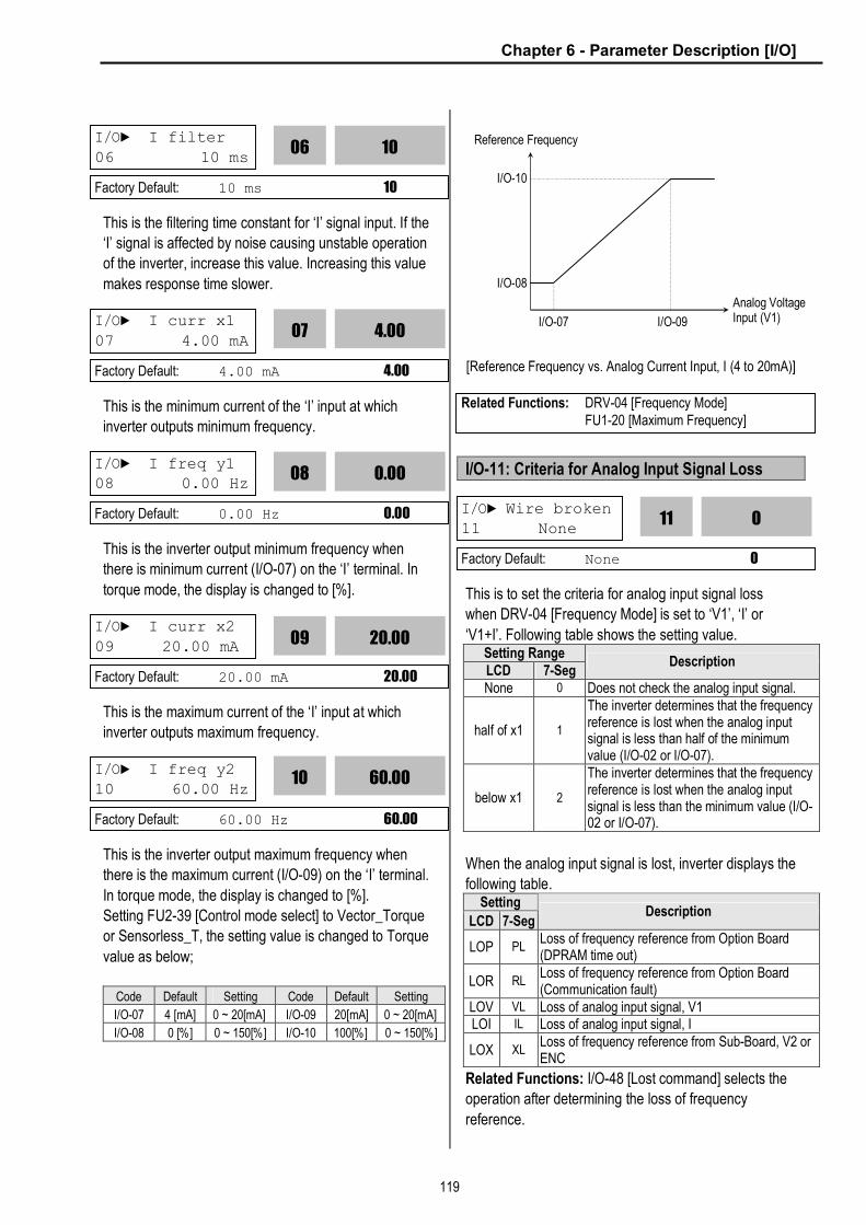
Chapter 6 - Parameter Description [I/O]
119
This is the filtering time constant for ‘I’ signal input. If the
‘I’ signal is affected by noise causing unstable operation
of the inverter, increase this value. Increasing this value
makes response time slower.
This is the minimum current of the ‘I’ input at which
inverter outputs minimum frequency.
This is the inverter output minimum frequency when
there is minimum current (I/O-07) on the ‘I’ terminal. In
torque mode, the display is changed to [%].
This is the maximum current of the ‘I’ input at which
inverter outputs maximum frequency.
This is the inverter output maximum frequency when
there is the maximum current (I/O-09) on the ‘I’ terminal.
In torque mode, the display is changed to [%].
Setting FU2-39 [Control mode select] to Vector_Torque
or Sensorless_T, the setting value is changed to Torque
value as below;
Code Default Setting Code Default Setting
I/O-07 4 [mA] 0 ~ 20[mA] I/O-09 20[mA] 0 ~ 20[mA]
I/O-08 0 [%] 0 ~ 150[%] I/O-10 100[%] 0 ~ 150[%]
[Reference Frequency vs. Analog Current Input, I (4 to 20mA)]
I/O-11: Criteria for Analog Input Signal Loss
This is to set the criteria for analog input signal loss
when DRV-04 [Frequency Mode] is set to ‘V1’, ‘I’ or
‘V1+I’. Following table shows the setting value. Setting Range LCD 7-Seg
Description
None 0 Does not check the analog input signal.
half of x1 1
The inverter determines that the frequency reference is lost when the analog input signal is less than half of the minimum value (I/O-02 or I/O-07).
below x1 2
The inverter determines that the frequency reference is lost when the analog input signal is less than the minimum value (I/O-02 or I/O-07).
When the analog input signal is lost, inverter displays the
following table. Setting
LCD 7-Seg Description
LOP PL Loss of frequency reference from Option Board (DPRAM time out)
LOR RL Loss of frequency reference from Option Board (Communication fault)
LOV VL Loss of analog input signal, V1 LOI IL Loss of analog input signal, I
LOX XL Loss of frequency reference from Sub-Board, V2 or ENC
Related Functions: I/O-48 [Lost command] selects the
operation after determining the loss of frequency
reference.
I/O► I filter
06 10 ms 10
06
Factory Default: 10 ms 10
I/O► I curr x1
07 4.00 mA 4.00
07
Factory Default: 4.00 mA 4.00
I/O► I freq y1 08 0.00 Hz
0.00
08
Factory Default: 0.00 Hz 0.00
I/O► I curr x2
09 20.00 mA 20.00
09
Factory Default: 20.00 mA 20.00
I/O► I freq y2 10 60.00 Hz
60.00
10
Factory Default: 60.00 Hz 60.00
Reference Frequency
I/O-10
Analog Voltage Input (V1)
I/O-08
I/O-07 I/O-09
Related Functions: DRV-04 [Frequency Mode] FU1-20 [Maximum Frequency]
I/O► Wire broken 11 None
0
11
Factory Default: None 0

Chapter 6 - Parameter Description [I/O]
120
The following table shows the selection in I/O-48. Setting Range LCD 7-Seg
Description
None 0 Continuous operating after loss of frequency reference.
FreeRun 1 Inverter cuts off its output after determining loss of frequency reference.
Stop 2 Inverter stops by its Decel pattern and Decel time after determining loss of frequency reference.
I/O-49 [Time out] sets the waiting time before
determining the loss of reference signal. Inverter waits to
determine the loss of a reference signal until times out.
Command frequency can be issued as Rpm when
setting rpm in DRV-16 [Hz/Rpm Display] and as Torque
reference when FU2-39 [Control Mode Select]. Torque
reference sets as the percentage of Rated Torque
Current.
☞ Note: I/O-48 and I/O-49 also apply when DRV-04 is set
to ‘Keypad-1’ or ‘Keypad-2’ for determining the loss of
command frequency.
I/O-12~14, 93~97: Multi-function Input Terminal ‘P1, P2, P3’, ‘RST’, ‘BX’, ‘JOG’, ‘FX’, ‘RX’ Define
Multi-function input terminals can be defined for many
different applications. The following table shows the
various definitions for them.
☞ Note: From 40HP and above inverter, only BX is
settable In I/O-94. Setting Range LCD 7-Seg
Description
Speed-L 0 Multi-step speed - Low Speed-M 1 Multi-step speed - Mid Speed-H 2 Multi-step speed - High XCEL-L 3 Multi-accel/decel - Low XCEL-M 4 Multi-accel/decel - Mid XCEL-H 5 Multi-accel/decel - High Dc-brake 6 DC injection braking during stop 2nd Func 7 Exchange to 2nd functions Exchange 8 Exchange to commercial power line -Reserved- 9 Reserved for future use
Up 10 Up drive Down 11 Down drive 3-Wire 12 3 wire operation
Ext Trip-A 13 External trip A Ext Trip-B 14 External trip B
iTerm Clear 15 Used for PID control
Open-loop 16 Exchange between PID mode and V/F mode
Main-drive 17 Exchange between Option and Inverter
Analog hold 18 Hold the analog input signal XCEL stop 19 Disable accel and decel
P Gain2 20 Used for PID control SEQ-L 21 Sequence operation - Low SEQ-M 22 Sequence operation - Mid SEQ-H 23 Sequence operation - High
Manual 24 Exchange between Sequence operation and Manual operation
Go step 25 Triggering Sequence operation (Auto-B)
Hold step 26 Hold last step (Auto-A) Trv Off.Lo 27
Trv Off.Hi 28 Used for Traverse Operation
Interlock1 29
Interlock2 30
Interlock3 31
Interlock4 32
Used for MMC operation
Speed-X 33 Additional Step frequency selection Reset 34 Reset
BX 35 Emergency Stop JOG 36 Jog FX 37 Forward Run/Stop RX 38 Reverse Run/Stop
Ana Change 39 Analog input Switch-over Pre excite 40 Pre excitation.
Spd/Torque 41 Speed/Torque Switch-over ASR P/PI 42 ASR P/PI control select
☞ Note: Refer to DRV-05~7, I/O-20~24, I/O-85~92 for I/O
~2, 33 Speed-L, Speed-M, Speed-H and Speed-X.
Related Functions: DRV-04 [Frequency Mode] I/O-02 [V1 Input Minimum Voltage] I/O-07 [I Input Minimum Current] I/O-48 [Lost command] I/O-49 [Time out]
I/O► P1 define
12 Speed-L 0
12
Factory Default: Speed-L 0
I/O► P2 define 13 Speed-M 1
13
Factory Default: Speed-M 1
I/O► P3 define
14 Speed-H 2
14
Factory Default: Speed-H 2

Chapter 6 - Parameter Description [I/O]
121
[Speed-L, Speed-M, Speed-H]
By setting P1, P2, P3 terminals to ‘Speed-L’, ‘Speed-M’
and ‘Speed-H’ respectively, inverter can operate at the
preset frequency set in DRV-05 ~ DRV-07 and I/O-20 ~
I/O-24.
The step frequencies are determined by the combination
of P1, P2 and P3 terminals as shown in the following
table.
Step
Frequency
Parameter
Code
Speed-H
(P3)
Speed-M
(P2)
Speed-L
(P1)
Step Freq-
0 DRV-00 0 0 0
Step Freq-
1 DRV-05 0 0 1
Step Freq-
2 DRV-06 0 1 0
Step Freq-
3 DRV-07 0 1 1
Step Freq-
4 I/O-21 1 0 0
Step Freq-
5 I/O-22 1 0 1
Step Freq-
6 I/O-23 1 1 0
Step Freq-
7 I/O-24 1 1 1
0: OFF, 1: ON
☞ I/O-20 [Jog Frequency] can be used as one of the step
frequencies.
☞ If the ‘Jog’ terminal is ON, inverter operates to Jog
frequency regardless of other terminal inputs.
[Multi-Step Frequency Operation]
☞ Note: The frequency for ‘Speed 0’ is determined by DRV-
04.
P1-CM ON ON
Output Frequency
Time
Time
P2-CM ON ON Time
P3-CM ON Time
JOG-CM ON Time
FX-CM ON Time
RX-CM ON Time
ON ON
Step 0
Step 1
Step 2
Step 3
Step 4
Step 5
Step 6
Step 7
Jog
Related Functions: DRV-05 ~ DRV-07 [Step Frequency] I/O-20 [Jog Frequency] I/O-20 ~ I/O-24 [Step Frequency]

Chapter 6 - Parameter Description [I/O]
122
[XCEL-L, XCEL-M, XCEL-H]
By setting P1, P2 and P3 terminals to ‘XCEL-L’, ‘XCEL-
M’ and ‘XCEL-H’ respectively, up to 8 different Accel and
Decel times can be used. The Accel/Decel time is set in
DRV-01 ~ DRV-02 and I/O-25 ~ I/O-38.
The Accel/Decel time is determined by the combination
of P1, P2 and P3 terminals as shown in the following
table.
Accel/Decel
Time
Parameter
Code
XCEL-H
(P3)
XCEL-M
(P2)
XCEL-L
(P1)
Accel Time-0 DRV-01
Decel Time-0 DRV-02 0 0 0
Accel Time-1 I/O-25
Decel Time-1 I/O-26 0 0 1
Accel Time-2 I/O-27
Decel Time-2 I/O-28 0 1 0
Accel Time-3 I/O-29
Decel Time-3 I/O-30 0 1 1
Accel Time-4 I/O-31
Decel Time-4 I/O-32 1 0 0
Accel Time-5 I/O-34
Decel Time-5 I/O-35 1 0 1
Accel Time-6 I/O-36
Decel Time-6 I/O-37 1 1 0
Accel Time-7 I/O-38
Decel Time-7 I/O-39 1 1 1
0: OFF, 1: ON
[Multi-Accel/Decel Time Operation]
[Dc-brake]
DC Injection Braking can be activated during inverter
stopped by configuring one of the multi-function input
terminals (P1, P2, P3) to ‘Dc-bake’. To activate the DC
Injection Braking, close the contact on the assigned
terminal while the inverter is stopped.
[Exchange]
Exchange is used to bypass the motor from the inverter
line to commercial power or the opposite. To bypass the
motor to commercial line, set the ‘Exchange’ function in
multi-function output terminal and ‘INV line’, ‘COMM line’
function in multi-function output terminal. Speed search
function (FU2-22) is activated automatically during
exchanging operation.
M2
U
V
W
G
R
S
T
FX
RX
P1
P3
CM
VR
V1
I
5G
FM
5G
30A
30B
30C
AXA
AXC
P2
MOTOR
Potentiometer (1 kohm, 1/2W)
Speed signal Input2
Forward Run/Stop
Reverse Run/Stop
‘Exchange’
Common Terminal
Factory Setting: ‘Speed-L’ ‘Speed-M’ ‘Speed-H’
Power supply for speed signal: + 11V, 10mA
Speed signal input: 0 ~ 10V
Speed signal input: 4 ~20mA (250ohm)
Common for VR, V1, I
Shield
MCCB
M1
M2
AC220V Line
M1
M1
[Wiring to By-Pass Motor to Commercial line]
P1-CM ON
Output Frequency
Time
Time
P2-CM ON Time
P3-CM ON Time
FX-CM ON Time
ON ON ON
ON
Ref.Freq.
Time 0 Time 1 Time 2 Time 3 Time 4 Time 5 Time 6 Time 7
Related Functions: I/O-25 ~ I/O-38 [1st ~7th Accel/Decel Time]
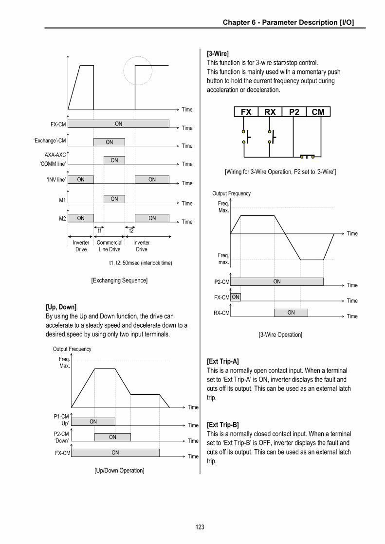
Chapter 6 - Parameter Description [I/O]
123
[Exchanging Sequence]
[Up, Down]
By using the Up and Down function, the drive can
accelerate to a steady speed and decelerate down to a
desired speed by using only two input terminals.
[Up/Down Operation]
[3-Wire]
This function is for 3-wire start/stop control.
This function is mainly used with a momentary push
button to hold the current frequency output during
acceleration or deceleration.
[Wiring for 3-Wire Operation, P2 set to ‘3-Wire’]
[3-Wire Operation]
[Ext Trip-A]
This is a normally open contact input. When a terminal
set to ‘Ext Trip-A’ is ON, inverter displays the fault and
cuts off its output. This can be used as an external latch
trip.
[Ext Trip-B]
This is a normally closed contact input. When a terminal
set to ‘Ext Trip-B’ is OFF, inverter displays the fault and
cuts off its output. This can be used as an external latch
trip.
P1-CM ‘Up’ ON
Output Frequency
Time
Time
P2-CM ‘Down’
ON Time
FX-CM ON Time
Freq.Max.
FX RX P2 CM
P2-CM ON
Output Frequency
Time
Time
FX-CM ON Time
RX-CM ON Time
Freq.Max.
Freq.max.
‘Exchange’-CM
FX-CM ON
Time
Time
ON Time
AXA-AXC
‘COMM line’ ON
Time
M1 ON Time
M2 ON Time
ON
t1 t2
Inverter Drive
Inverter Drive
Commercial Line Drive
t1, t2: 50msec (interlock time)
‘INV line’ ON Time
ON

Chapter 6 - Parameter Description [I/O]
124
[iTerm Clear]
This function is used for PID control. When this terminal
is ON, the accumulated value by I-Gain is set to ‘0’.
Refer to PID Control Block Diagram.
[Open-loop]
This is used to exchange the control mode of inverter
from PID mode (Close Loop) to V/F mode (Open Loop).
DRV-03 [Drive Mode] and DRV-04 [Frequency Mode]
are applied when the mode has been changed.
☞ Note: This function can be used only when the inverter is
stopped.
[Main-drive]
When an option board (like RS485, DeviceNet, F-Net) is
installed and used for the frequency setting and the
run/stop command, the inverter operation can be
changed to manual operation using this function without
changing parameters.
FU1-02 [Frequency Mode] and FU1-01 [Drive Mode] are
applied when the mode has been changed.
☞ Note: this function can be used only when the inverter is
stopped.
[Analog hold]
When there is an analog input signal for frequency
reference and ‘Analog hold’ terminal is ON, inverter fixes
its output frequency regardless of the frequency
reference change. The changed frequency reference is
applied when the terminal is OFF.
This function is useful when a system requires constant
speed after acceleration.
[Analog hold Operation]
[XCEL stop]
Inverter stops accelerating and decelerating when this
terminal is ON.
[P Gain2]
This function is used to change P-Gain during PID
operation. When this terminal is ON, PID controller
changes P-Gain with PID P2-Gian set in FU2-59.
Refer to PID Control Block Diagram.
[SEQ-L, SEQ-M, SEQ-H]
These functions are used for Auto drive (I/O-50).
Five different sequences can be selected according to
the combination of these terminals. Eight step
frequencies, Accel/Decel time and steady speed time
can be set for each sequence. The following table shows
the sequence of selection.
Sequence # Parameter
Code
Speed-H
(P3)
Speed-M
(P2)
Speed-L
(P1)
Sequence 1 0 0 1
Sequence 2 0 1 0
Sequence 3 1 0 0
Sequence 4 0 1 1
Sequence 5
I/O-50 ~
I/O-84
1 0 1
0: OFF, 1: ON
☞ Note: The inverter stops after finishing all steps of that
sequence once the Auto (Sequence) operation is started.
To stop the inverter during sequence operation, use ‘BX’
terminal on the control terminal strip.
[Manual]
This is used to exchange the operation mode of inverter
from Auto (Sequence) to manual operation.
DRV-03 [Drive Mode] and DRV-04 [Frequency Mode]
are applied when the mode has been changed.
☞ Note: This function can be used only when the inverter is
stopped.
[Go step]
This is used to trigger the next step in a sequence of
Auto-B operation.
P1-CM ‘Analog hold’
Reference Frequency,
Output frequency
Time
ON Time
Reference Frequency
Output Frequency
Related Functions: I/O-51 ~ I/O-84 [Sequence Operation]

Chapter 6 - Parameter Description [I/O]
125
[Hold step]
This is used to hold the last step frequency in Auto-A
operation.
[‘Go step’ in Auto-B Operation]
[‘Hold step’ in Auto-A Operation]
[Trv Off.Lo]
This function is used to make negative offset during
traverse operation.
[Trv Off.Hi]
This function is used to make positive offset during
traverse operation.
[Interlock1, 2, 3, 4]
This function is used for MMC operation. Refer to MMC
operation.
[Reset]
This function is set to use it as fault reset terminal when
ON.
[BX]
This function is set to use it as Emergency Stop terminal
when ON.
[JOG]
This function is set to use Jog operation terminal when
ON.
[FX]
This function is set to issue Forward Run.
[RX]
This function is set to issue Reverse Run.
[Ana Change]
Inverter changes its frequency reference source from V1
to I when ON.
[Pre excite]
This setting switches the inverter in pre-exciting state
when assignning Pre excite to the desired terminal. This
function applies only the exciting current to a motor in
Sensorless_S control. In Vector_SPD control, the
inverter conducts pre-exciting to start a motor after the
magnetic-flux is established and holding torque, even
200% of motor nominal torque is guaranteed. When the
operation command is set to ON, the state changes from
pre-exciting to normal.
Related Functions: I/O-51 ~ I/O-84 [Sequence Operation]
Time
P1-CM ‘SEQ-L’ ON
Output Frequency
Time
ON Time
ON Time
P2-CM‘SEQ-M’
P3-CM‘Go step’ ON ON ON ON
Minimum 100msec
SEQ1 / 2F
SEQ2 / 2F
SEQ1 / 1F
SEQ3 / 2F
SEQ3 / 1F
Sequence 1 Sequence 3 Sequence 2
P1-CM ‘SEQ-L’
Output Frequency
Time
Time
Time
P2-CM‘SEQ-M’
P3-CM ‘Hold step’ ON
SEQ2 / 2F
SEQ1 / 2F
SEQ2 / 1FSEQ1 / 1F
Sequence 1 Sequence 2
ON
ON
Time
Related Functions: APP-06 ~ APP-07 [Traverse Offset]
Related Functions: APP-06 ~ APP-07 [Traverse Offset]
Related Functions: APP-29 [Inter-Lock Selection]
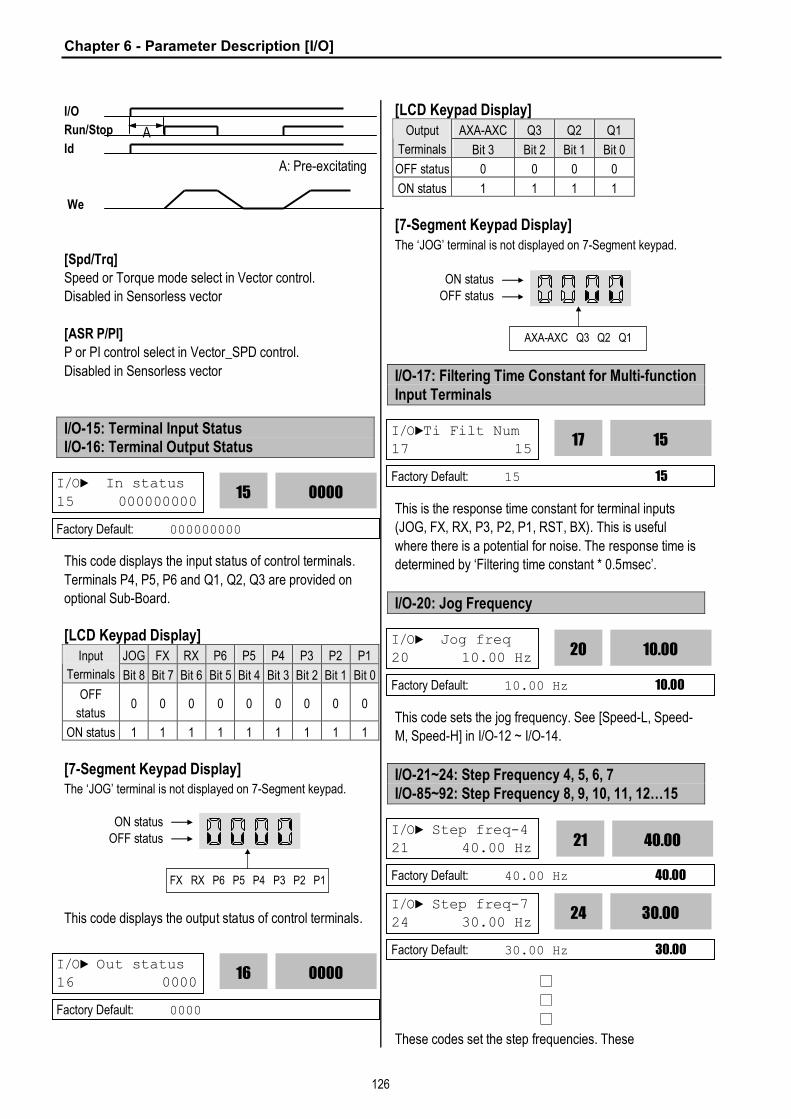
Chapter 6 - Parameter Description [I/O]
126
I/O
Run/Stop
Id
A: Pre-excitating
We
[Spd/Trq]
Speed or Torque mode select in Vector control.
Disabled in Sensorless vector
[ASR P/PI]
P or PI control select in Vector_SPD control.
Disabled in Sensorless vector
I/O-15: Terminal Input Status I/O-16: Terminal Output Status
This code displays the input status of control terminals.
Terminals P4, P5, P6 and Q1, Q2, Q3 are provided on
optional Sub-Board.
[LCD Keypad Display] JOG FX RX P6 P5 P4 P3 P2 P1 Input
Terminals Bit 8 Bit 7 Bit 6 Bit 5 Bit 4 Bit 3 Bit 2 Bit 1 Bit 0
OFF
status 0 0 0 0 0 0 0 0 0
ON status 1 1 1 1 1 1 1 1 1
[7-Segment Keypad Display] The ‘JOG’ terminal is not displayed on 7-Segment keypad.
This code displays the output status of control terminals.
[LCD Keypad Display] AXA-AXC Q3 Q2 Q1 Output
Terminals Bit 3 Bit 2 Bit 1 Bit 0
OFF status 0 0 0 0
ON status 1 1 1 1
[7-Segment Keypad Display] The ‘JOG’ terminal is not displayed on 7-Segment keypad.
I/O-17: Filtering Time Constant for Multi-function Input Terminals
This is the response time constant for terminal inputs
(JOG, FX, RX, P3, P2, P1, RST, BX). This is useful
where there is a potential for noise. The response time is
determined by ‘Filtering time constant * 0.5msec’.
I/O-20: Jog Frequency
This code sets the jog frequency. See [Speed-L, Speed-
M, Speed-H] in I/O-12 ~ I/O-14.
I/O-21~24: Step Frequency 4, 5, 6, 7 I/O-85~92: Step Frequency 8, 9, 10, 11, 12…15
□
□
□
These codes set the step frequencies. These
I/O► In status
15 000000000 0000 15
Factory Default: 000000000
OFF status ON status
FX RX P6 P5 P4 P3 P2 P1
I/O► Out status 16 0000
0000
16
Factory Default: 0000
OFF status ON status
AXA-AXC Q3 Q2 Q1
I/O►Ti Filt Num 17 15
15
17
Factory Default: 15 15
I/O► Jog freq 20 10.00 Hz 10.00
20
Factory Default: 10.00 Hz 10.00
I/O► Step freq-4 21 40.00 Hz 40.00
21
Factory Default: 40.00 Hz 40.00
I/O► Step freq-7 24 30.00 Hz
30.00
24
Factory Default: 30.00 Hz 30.00
A

Chapter 6 - Parameter Description [I/O]
127
frequencies are applied when the multi-function input
terminals (P1, P2, P3, RST, BX, JOG, FX and RX) select
the step. See [Speed-L, Speed-M, Speed-H, Speed-X] in
I/O-12 ~14, I/O-33.
Step
Freq. Code Spd-X
Spd-H
(P3)
Spd-
M(P2)
Spd-L
(P1)
Jog
Ter.
Step
Freq-0 DRV-00 0 0 0 0 0
Jog I/O-20 X X X X 1
Step
Freq-1 DRV-05 0 0 0 1 0
Step
Freq-2 DRV-06 0 0 1 0 0
Step
Freq-3 DRV-07 0 0 1 1 0
Step
Freq-4 I/O-21 0 1 0 0 0
Step
Freq-5 I/O-22 0 1 0 1 0
Step
Freq-6 I/O-23 0 1 1 0 0
Step
Freq-7 I/O-24 0 1 1 1 0
Step
Freq-8 I/O-85 1 0 0 0 0
Step
Freq-9 I/O-86 1 0 0 1 0
Step
Freq-10 I/O-87 1 0 1 0 0
Step
Freq-11 I/O-88 1 0 1 1 0
Step
Freq-12 I/O-89 1 1 0 0 0
Step
Freq-13 I/O-90 1 1 0 1 0
Step
Freq-14 I/O-91 1 1 1 0 0
Step
Freq-15 I/O-92 1 1 1 1 0
7- 0: OFF, 1: ON, X: Jog
** Speed-X: The highest speed input bit (used when one of
RST, BX, JOG, FX, RX set to Speed-X)
☞ I/O-20 [Jog Frequency] can be used as one of the step
frequencies.
☞ If the ‘Jog’ terminal is ON, inverter operates to Jog
frequency regardless of other terminal inputs.
[‘JOG’ and ‘Multi-Step’ Operation]
I/O-25 ~ I/O-38: 1st ~ 7th Accel/Decel Time
□
□
□
These codes are applied when the multi-function input
terminals (P1, P2, P3) select the Accel/Decel time. See
[XCEL-L, XCEL-M, XCEL-H] in I/O-12 ~ I/O-14.
Related Functions: DRV-04 [Frequency mode] DRV-05 ~ DRV-07 [Step Frequency 1 ~ 3] I/O-12 ~ 14, 93~97 [Multi-function inputs] I/O-17 [Filtering Time Constant]
I/O► Acc time-1
25 20.0 sec 20.00
25
Factory Default: 20.0 sec 20.0
I/O► Dec time-7 38 20.0 sec
20
38
Factory Default: 20.0 sec 20.0
Related Functions: DRV-01 ~ DRV-02 [Accel/Decel Time] FU2-70 [Reference Freq. for Accel/Decel] FU2-71 [Accel/Decel Time Scale] I/O-12 ~ I/O-14 [Multi-function inputs]
P1-CM ON ON
Output Frequency
Time
Time
P2-CM ON ON Time
P3-CM ON Time
JOG-CM ON Time
FX-CM ON Time
RX-CM ON Time
ON ON
Step 0
Step 1
Step 2
Step 3
Step 4
Step 5
Step 6
Step 7
Jog
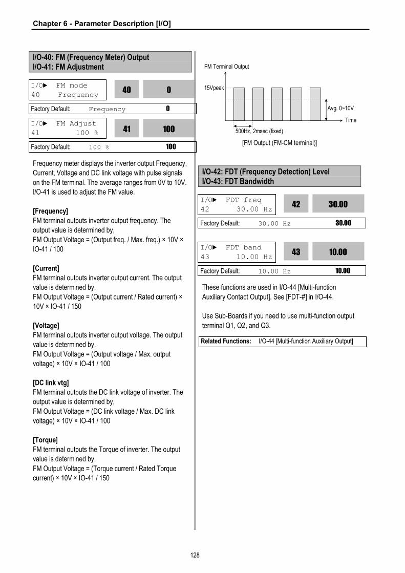
Chapter 6 - Parameter Description [I/O]
128
I/O-40: FM (Frequency Meter) Output I/O-41: FM Adjustment
Frequency meter displays the inverter output Frequency,
Current, Voltage and DC link voltage with pulse signals
on the FM terminal. The average ranges from 0V to 10V.
I/O-41 is used to adjust the FM value.
[Frequency]
FM terminal outputs inverter output frequency. The
output value is determined by,
FM Output Voltage = (Output freq. / Max. freq.) × 10V ×
IO-41 / 100
[Current]
FM terminal outputs inverter output current. The output
value is determined by,
FM Output Voltage = (Output current / Rated current) ×
10V × IO-41 / 150
[Voltage]
FM terminal outputs inverter output voltage. The output
value is determined by,
FM Output Voltage = (Output voltage / Max. output
voltage) × 10V × IO-41 / 100
[DC link vtg]
FM terminal outputs the DC link voltage of inverter. The
output value is determined by,
FM Output Voltage = (DC link voltage / Max. DC link
voltage) × 10V × IO-41 / 100
[Torque]
FM terminal outputs the Torque of inverter. The output
value is determined by,
FM Output Voltage = (Torque current / Rated Torque
current) × 10V × IO-41 / 150
[FM Output (FM-CM terminal)]
I/O-42: FDT (Frequency Detection) Level I/O-43: FDT Bandwidth
These functions are used in I/O-44 [Multi-function
Auxiliary Contact Output]. See [FDT-#] in I/O-44.
Use Sub-Boards if you need to use multi-function output
terminal Q1, Q2, and Q3.
I/O► FM mode 40 Frequency
0
40
Factory Default: Frequency 0
I/O► FM Adjust 41 100 % 100
41
Factory Default: 100 % 100
I/O► FDT freq 42 30.00 Hz
30.00
42
Factory Default: 30.00 Hz 30.00
I/O► FDT band
43 10.00 Hz 10.00
43
Factory Default: 10.00 Hz 10.00
Related Functions: I/O-44 [Multi-function Auxiliary Output]
FM Terminal Output
Time
15Vpeak
Avg. 0~10V
500Hz, 2msec (fixed)

Chapter 6 - Parameter Description [I/O]
129
I/O-44: Multi-function Auxiliary Contact Output define (AXA-AXC)
The auxiliary contact works (Close) when the defined
condition has occurred.
Setting Range
LCD 7-Seg Description
FDT-1 0 Output frequency arrival detection FDT-2 1 Specific frequency level detection FDT-3 2 Frequency detection with pulse
FDT-4 3 Frequency detection with contact closure
FDT-5 4 Frequency detection with contact closure (inverted FDT-4)
OL 5 Overload detection IOL 6 Inverter overload detection Stall 7 Stall prevention mode detection OV 8 Over voltage detection LV 9 Low voltage detection OH 10 Overheat detection
Lost Command 11 Lost command detection Run 12 Inverter running detection Stop 13 Inverter stop detection
Steady 14 Steady speed detection INV line 15
COMM line 16 Exchange signal outputs
Ssearch 17 Speed search mode detection Step pulse 18 Step detection in Auto mode Seq pulse 19 Sequence detection in Auto mode
Ready 20 Inverter ready detection Trv. ACC 21 Traverse acceleration frequency Trv. DEC 22 Traverse deceleration frequency
MMC 23 Used for MMC operation Zspd Dect 24 0 rpm Detection in Vector control Torq Dect 25 Torque Detection
[FDT-1]
When the output frequency reaches the reference
frequency (target frequency), AXA-AXC terminal is
CLOSED.
[AXA-AXC configured as ‘FDT-1’]
[FDT-2]
AXA-AXC is CLOSED when the reference frequency is
in I/O-43 [FDT Bandwidth] centered on I/O-42 [FDT
Frequency], and the output frequency reaches I/O-43
centered on I/O-42.
[AXA-AXC configured as ‘FDT-2’]
[FDT-3]
AXA-AXC is CLOSED when the output frequency
reaches the band centered on the FDT frequency. The
output is OPENED when the output frequency goes
outside the FDT bandwidth centered on the FDT
frequency.
I/O► Aux mode 44 Run
Factory Default: Run 12
AXA-AXC CLOSED
Output Frequency
Time
Time
I/O-43 / 2
I/O-42
Reference Frequency
AXA-AXC CLOSED
Output Frequency
Time
Time
I/O-43 / 2
Reference Frequency
12
44
FM-5G
10 V
0 % 100
I/O-41*10 V
Output V
I/O-40

Chapter 6 - Parameter Description [I/O]
130
[AXA-AXC configured as ‘FDT-3’]
[FDT-4]
AXA-AXC is CLOSED when the output frequency
reaches the FDT frequency. The output is OPENED
when the output frequency goes below the FDT
bandwidth centered on the FDT frequency.
[AXA-AXC configured as ‘FDT-4’]
[FDT-5]
This is the inverted output of [FDT-4].
[AXA-AXC configured as ‘FDT-5’]
[OL]
AXA-AXC is CLOSED when the output current has
reached the FU1-54 [Overload Warning Level] for the
FU1-55 [Overload Warning Time].
[AXA-AXC configured as ‘OL’]
[IOL]
AXA-AXC is CLOSED when the output current is above
the 150% of rated inverter current for 36 seconds. If this
situation is continued for one minute, the inverter will cut
off its output and displays ‘IOL’ (Inverter overload) Trip.
See the nameplate for the rated inverter current.
[AXA-AXC configured as ‘IOL’]
AXA-AXC ON
Output Frequency
Time
Time
I/O-43 / 2
ON
I/O-42
AXA-AXC
Output Frequency
Time
Time
I/O-43 / 2
CLOSED
I/O-42
AXA-AXC
Output Frequency
Time
Time
I/O-43 / 2
ON
I/O-42
ON
Related Functions: FU1-54 [Overload Warning Level] FU1-55 [Overload Warning Time]
t1: FU1-55 [Overload Warning Time]
Output Current
Time
Time
FU1-54[OL level]
FU1-54[OL level]
AXA-AXC ON
t1 t1
Output Current
Time
Time
150% of Rated Inverter Current
AXA-AXC ON
36sec
150% of Rated Inverter Current
24sec

Chapter 6 - Parameter Description [I/O]
131
[Stall]
AXA-AXC is CLOSED when the inverter is on the stall
prevention mode.
[AXA-AXC configured as ‘Stall’]
[OV]
AXA-AXC is CLOSED when the DC link voltage is above
the Over-voltage level.
[AXA-AXC configured as ‘OV’]
[LV]
AXA-AXC is CLOSED when the DC link voltage is below
the Low-voltage level.
[AXA-AXC configured as ‘LV’]
[OH]
AXA-AXC is CLOSED when the heat sink of the inverter
is above the reference level.
[Lost Command]
AXA-AXC is CLOSED when frequency reference is lost.
[Run]
AXA-AXC is CLOSED when the inverter is running.
[Stop]
AXA-AXC is CLOSED when the inverter is stopped.
[INV line, COMM line]
This function is used in conjunction with ‘Exchange’
function of multi-function input for commercial line
exchange. To use both signal of ‘INV line’ and ‘COMM
line’, the optional Sub-A or Sub-C board must be
installed.
[AXA-AXC configured as ‘COMM line’ and ‘Q1’ as INV line’]
Output Current
Time
Output Frequency
Time
FU1-60 [Stall Level]
FU1-60 [Stall Level]
Time CLOSED AXA-AXC
Related Functions: FU1-59 [Stall Prevention Mode] FU1-60 [Stall Prevention Level]
AXA-AXC ON
DC Link Voltage
Time
Time
LV Level (200V DC or 400V DC)
AXA-AXC ON
DC Link Voltage
Time
Time
OV Level (380V DC or 760V DC)
Related Functions: I/O-11 [Criteria for Analog Signal Loss] I/O-48 [Operating Method at Signal Loss] I/O-49 [Waiting Time for Time Out]
‘Exchange’-CM
FX-CM ON
Output Frequency
Time
Time
ON Time
AXA-AXC
‘COMM line’ ON
Time
ON Time
ON
t1 t2
Inverter Drive
Inverter Drive
Commercial Line Drive
t1, t2: 50msec (interlock time)
Speed Search
Q1-EXTG
‘INV line’
Related Functions: I/O-12 ~ I/O-14 [Multi-function input] - [Exchange]

Chapter 6 - Parameter Description [I/O]
132
[Ssearch]
AXA-AXC is CLOSED during the inverter is speed
searching.
[Step pulse]
When Auto (Sequence) operation is selected in I/O-50,
AXA-AXC outputs pulse signals on every step.
[AXA-AXC configured as ‘Step pulse’]
[Seq pulse]
When Auto (Sequence) operation is selected in I/O-50,
AXA-AXC outputs pulse signals on the last step.
[AXA-AXC configured as ‘Step pulse’]
[Ready]
AXA-AXC is CLOSED when the inverter is ready to run.
[Trv. ACC]
CLOSED when output frequency reaches Accel
frequency.
[Trv. DEC]
CLOSED when output frequency reaches Decel
frequency.
[MMC]
Automatically set to ‘MMC’ when ‘MMC’ is selected in
APP-01.
[Zspd Dect]
0 rpm detection signal in Vector Control
[Torq Dect]
Torque detection signal in Vector and Sensorless Vector
Control.
Output Frequency
Time
Seq# / 2F
Seq# / 1F
Seq# / 3F
1T 1S 2T 2S 3T 3S
1D (Forward)
2D (Forward)
3D (Reverse)
DRV-02
AXA-AXC ‘Step pulse’ Time
ON
Minimum 100msec
AXA-AXC ‘Step pulse’
P1-CM ‘SEQ-L’ ON
Output Frequency
Time
ON Time
ON Time
P2-CM‘SEQ-M’
P3-CM‘Go step’ ON ON ON ON
SEQ1 / 2F
SEQ2 / 2F
SEQ1 / 1F
SEQ3 / 2F
SEQ3 / 1F
Sequence 1 Sequence 3 Sequence 2
ON Time
ON ON ON ON
Minimum 100msec
Time
Related Functions: I/O-50 ~ I/O-84 [Auto Operation]

Chapter 6 - Parameter Description [I/O]
133
I/O-45: Fault Output Relay (30A, 30B, 30C)
This function is used to allow the fault output relay to
operate when a fault occurs. The output relay terminal is
30A, 30B, 30C where 30A-30C is a normally open
contact and 30B-30C is a normally closed contact.
Bit Settin
g Display Description
0 000 Fault output relay does not
operate at ‘Low voltage’ trip. Bit 0
(LV) 1 001
Fault output relay operates at
‘Low voltage’ trip.
0 000 Fault output relay does not
operate at any fault. Bit 1
(Trip) 1 010
Fault output relay operates at
any fault except ‘Low voltage’
and ‘BX’ (inverter disable) fault.
0 000
Fault output relay does not
operate regardless of the retry
number. Bit 2
(Retry)
1 100
Fault output relay operates
when the retry number set in
FU2-26 decreases to 0 by
faults.
☞ When several faults occurred at the same time, Bit 0 has
the first priority.
I/O-46: Inverter Number I/O-47: Baud Rate
This code sets the inverter number. This number is used
in communication between inverter and communication
board.
This code sets the communication speed. This is used in
communication between inverter and communication
board.
I/O-48: Operating at Loss of Freq. Reference I/O-49: Waiting Time after Loss of Freq. Reference
There are two kinds of loss of frequency reference. One
is the loss of digital frequency reference and the other is
of analog frequency reference.
Loss of digital frequency reference is applied when DRV-
04 [Frequency Mode] is set to ‘Keypad-1’ or ‘Kepad-2’.
At this time, the ‘Loss’ means the communication error
between inverter and keypad or communication board
during the time set in I/O-49.
Loss of analog frequency reference is applied when
DRV-04 [Frequency Mode] is set to other than ‘Keypad-
1’ or ‘Kepad-2’. At this time, the ‘Loss’ is determined by
the criteria set in I/O-11 [Criteria for Analog Input Signal
Loss].
Setting Range
LCD 7-Seg Description
None 0 Inverter keeps on operating at the previous frequency.
FreeRun (Coast to stop)
1 Inverter cuts off its output.
Stop 2 Inverter stops with Decel time (DRV-02) and Decel pattern (FU1-26).
This is the time inverter determines whether there is a
frequency reference or not. If there is no frequency
reference satisfying I/O-11 during this time, inverter
determines that it has lost of frequency reference.
I/O► Relay mode 45 010
010
45
Factory Default: 010 010
I/O► Inv No.
46 1 1
46
Factory Default: 1 1
I/O► Baud rate 47 9600 bps 9600
47
Factory Default: 9600 9600
Related Functions: DRV-12 [Fault Display] FU2-26 [Retry number]
I/O►Lost command
48 None 0
48
Factory Default: None 0
I/O► Time out 49 1.0 sec
1.0
49
Factory Default: 1.0 sec 1.0
Related Functions: DRV-04 [Frequency Mode] I/O-11 [Criteria for Analog Signal Loss]

Chapter 6 - Parameter Description [I/O]
134
I/O-50: Auto (Sequence) Operation I/O-51: Sequence Number Selection (Seq #) I/O-52: The Number of Steps of Sequence #
There are two modes of ‘Auto-A’ and ‘Auto-B’ in Auto
mode. Auto operation is activated by the multi-function
input terminals set to [SEQ-L], [SEQ-M], [SEQ-H] and
[Go step] in I/O-12 ~ I/O-14.
This code selects the sequence to set frequency,
transient time, steady speed time and motor direction the
steps.
This code sets the number of steps to use for the
sequence number selected in I/O-51.
[Auto-A]
This mode will allow the inverter to operate automatically
followed by its pre-programmed sequence. According to
this sequence, eight different steps of Frequency,
Transient Time, Steady Speed time and Motor Direction
can be initiated with only a single multi-function input
contact closure (I/O-12 ~ I/O-14). The sequence and
steps are set in I/O-51 ~ I/O-84.
Step
Frequency
Parameter
Code
Speed-H
(P3)
Speed-M
(P2)
Speed-L
(P1)
Sequence 1 0 0 1
Sequence 2 0 1 0
Sequence 3 1 0 0
Sequence 4 0 1 1
Sequence 5
I/O-50 ~
I/O-84
1 0 1
0: OFF, 1: ON
[Example 1 of ‘Auto-A’ operation]
[Example 2 of ‘Auto-A’ operation]
I/O► Auto mode 50 None
0
50
Factory Default: None 0
Output Frequency
Time
Seq1 / 2F
Seq1 / 1F
Seq1 / 3F
1T 1S 2T 2S 3T 3S
1D (Forward)
2D (Forward)
3D (Reverse)
P1-CM ‘SEQ-L’ ON
Time
I/O► Seq select 51 3
1
51
Factory Default: 1 1
I/O► Step number 52 2 2
52
Factory Default: 2 2
P1-CM ‘SEQ-L’ ON
Output Frequency
Time
ON Time
P2-CM ‘SEQ-M’
SEQ1 / 2F
SEQ2 / 2F
SEQ1 / 1F
SEQ3 / 2F
SEQ3 / 1F
Sequence 1 Sequence 3 Sequence 2
Time
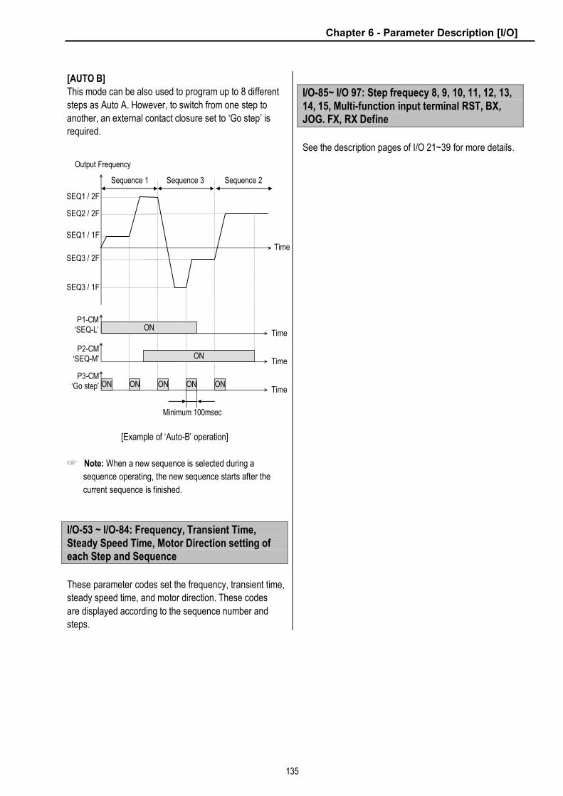
Chapter 6 - Parameter Description [I/O]
135
[AUTO B]
This mode can be also used to program up to 8 different
steps as Auto A. However, to switch from one step to
another, an external contact closure set to ‘Go step’ is
required.
[Example of ‘Auto-B’ operation]
☞ Note: When a new sequence is selected during a
sequence operating, the new sequence starts after the
current sequence is finished.
I/O-53 ~ I/O-84: Frequency, Transient Time, Steady Speed Time, Motor Direction setting of each Step and Sequence
These parameter codes set the frequency, transient time,
steady speed time, and motor direction. These codes
are displayed according to the sequence number and
steps.
I/O-85~ I/O 97: Step frequecy 8, 9, 10, 11, 12, 13, 14, 15, Multi-function input terminal RST, BX, JOG. FX, RX Define
See the description pages of I/O 21~39 for more details.
P1-CM ‘SEQ-L’ ON
Output Frequency
Time
ON Time
ON Time
P2-CM‘SEQ-M’
P3-CM‘Go step’ ON ON ON ON
Minimum 100msec
SEQ1 / 2F
SEQ2 / 2F
SEQ1 / 1F
SEQ3 / 2F
SEQ3 / 1F
Sequence 1 Sequence 3 Sequence 2
Time
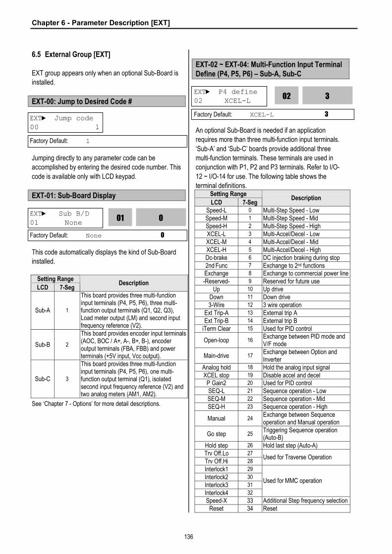
Chapter 6 - Parameter Description [EXT]
136
6.5 External Group [EXT]
EXT group appears only when an optional Sub-Board is
installed.
EXT-00: Jump to Desired Code #
Jumping directly to any parameter code can be
accomplished by entering the desired code number. This
code is available only with LCD keypad.
EXT-01: Sub-Board Display
This code automatically displays the kind of Sub-Board
installed.
Setting Range
LCD 7-Seg Description
Sub-A 1
This board provides three multi-function input terminals (P4, P5, P6), three multi-function output terminals (Q1, Q2, Q3), Load meter output (LM) and second input frequency reference (V2).
Sub-B 2
This board provides encoder input terminals (AOC, BOC / A+, A-, B+, B-), encoder output terminals (FBA, FBB) and power terminals (+5V input, Vcc output).
Sub-C 3
This board provides three multi-function input terminals (P4, P5, P6), one multi-function output terminal (Q1), isolated second input frequency reference (V2) and two analog meters (AM1, AM2).
See ‘Chapter 7 - Options’ for more detail descriptions.
EXT-02 ~ EXT-04: Multi-Function Input Terminal Define (P4, P5, P6) – Sub-A, Sub-C
An optional Sub-Board is needed if an application
requires more than three multi-function input terminals.
‘Sub-A’ and ‘Sub-C’ boards provide additional three
multi-function terminals. These terminals are used in
conjunction with P1, P2 and P3 terminals. Refer to I/O-
12 ~ I/O-14 for use. The following table shows the
terminal definitions. Setting Range
LCD 7-Seg Description
Speed-L 0 Multi-Step Speed - Low Speed-M 1 Multi-Step Speed - Mid Speed-H 2 Multi-Step Speed - High XCEL-L 3 Multi-Accel/Decel - Low XCEL-M 4 Multi-Accel/Decel - Mid XCEL-H 5 Multi-Accel/Decel - High Dc-brake 6 DC injection braking during stop 2nd Func 7 Exchange to 2nd functions Exchange 8 Exchange to commercial power line -Reserved- 9 Reserved for future use
Up 10 Up drive Down 11 Down drive 3-Wire 12 3 wire operation
Ext Trip-A 13 External trip A Ext Trip-B 14 External trip B
iTerm Clear 15 Used for PID control
Open-loop 16 Exchange between PID mode and V/F mode
Main-drive 17 Exchange between Option and Inverter
Analog hold 18 Hold the analog input signal XCEL stop 19 Disable accel and decel
P Gain2 20 Used for PID control SEQ-L 21 Sequence operation - Low SEQ-M 22 Sequence operation - Mid SEQ-H 23 Sequence operation - High
Manual 24 Exchange between Sequence operation and Manual operation
Go step 25 Triggering Sequence operation (Auto-B)
Hold step 26 Hold last step (Auto-A) Trv Off.Lo 27
Trv Off.Hi 28 Used for Traverse Operation
Interlock1 29
Interlock2 30
Interlock3 31
Interlock4 32
Used for MMC operation
Speed-X 33 Additional Step frequency selection Reset 34 Reset
EXT► Jump code 00 1
Factory Default: 1
EXT► Sub B/D 01 None
0
01
Factory Default: None 0
EXT► P4 define 02 XCEL-L
3
02
Factory Default: XCEL-L 3

Chapter 6 - Parameter Description [EXT]
137
Setting Range
LCD 7-Seg Description
BX 35 Emergency Stop JOG 36 Jog FX 37 Forward Run/Stop RX 38 Reverse Run/Stop
Ana Change 39 Analog input Switch-over Pre excite 40 Pre excitation.
Spd/Torque 41 Speed/Torque Switch-over ASR P/PI 42 ASR P/PI control select
EXT-05: V2 Mode Selection – Sub-A, Sub-C
‘V2’ signal can be used as the frequency reference and
override function.
[None]
V2 signal is not used.
[Override]
‘V2’ signal override the frequency reference signal (V1, I,
V1+I) selected in DRV-04.
[Reference]
‘V2’ signal is used as the frequency reference. At this
time, the frequency reference selected in DRV-04 is
ignored.
EXT-06 ~ EXT-10: Analog Voltage Input (V2) Signal Adjustment – Sub-A, Sub-C
This is used to adjust the analog voltage input signal
when the frequency is referenced or overridden by the
‘V2’ control terminal. This function is applied when EXT-
05 is set to ‘Override’ or ‘Reference’. Reference
Frequency versus Analog Voltage Input Curve can be
made by four parameters of EXT-07 ~ EXT-10.
This is the filtering time constant for ‘V2’ signal input. If
the ‘V2’ signal is affected by noise causing unstable
operation of the inverter, increase this value. Increasing
this value may make response time slower.
This is the minimum voltage of the ‘V2’ input at which the
inverter outputs minimum frequency.
This is the minimum frequency the inverter outputs when
there is the minimum voltage (EXT-07) on the ‘V2’
terminal.
This is the maximum voltage of the ‘V2’ input at which
the inverter outputs maximum frequency.
This is the maximum frequency the inverter outputs
when there is the maximum voltage (EXT-09) on the ‘V2’
terminal.
EXT► V2 mode 05 None
0
05
Factory Default: None 0
EXT► V2 filter 06 10 ms 10
06
Factory Default: 10 ms 10
EXT► V2 volt x1
07 0.00 V
Factory Default: 0.00 V 0.00
EXT► V2 volt y1 08 0.00 Hz
0.00
08
Factory Default: 0.00 Hz 0.00
EXT► V2 volt x2
09 0.00 V 10.00
09
Factory Default: 10.00 V 10.00
EXT► V2 volt y2 10 60.00 Hz 60.00
10
Factory Default: 60.00 Hz 60.00
0.00
07

Chapter 6 - Parameter Description [EXT]
138
[Reference Frequency vs. Analog Voltage Input, V2 (0 to 10V)]
EXT-12: Usage of Pulse Input Signal – Sub-B
This function is to select the usage of encoder pulse
signal of ‘Sub-B’ board. The pulse signal from encoder
can be used as the motor speed feedback or frequency
reference.
[None]
The encoder pulse signal is not used.
[Feed-back]
The encoder pulse signal is used as the motor speed
feedback. The inverter can maintain the motor speed
constantly, regardless of the load fluctuation, by using
the encoder feedback. Set the encoder pulse method
and the number of pulse in EXT-15 and 16. Main speed
is set in DRV-04 [Frequency mode]. The encoder pulse
related functions must be set correctly for better
performance in EXT-15 ~ EXT-24.
Code LCD Display Setting in Feed back
EXT-12 F mode Feed-back
EXT-15 F pulse set A+B
EXT-16 F pulse num 360 ~ 4096
EXT-22 PG P-gain 0 ~ 30000
EXT-23 PG I-gain 0 ~ 30000
EXT-24 PG Slip Freq 0 ~ 200[%]
EXT-25 ASR P-Gain 10 ~ 500[%]
EXT-26 ASR I-Gain 10 ~ 9999[mSec]
EXT-27 Trq + Limit 0 ~ 200[%]
EXT-28 Trq – Limit 0 ~ 200[%]
[Reference]
The encoder pulse signal is used as the frequency
reference. When this function is selected, the frequency
reference selected in DRV-04 is ignored. Reference
Frequency versus Pulse Input Curve can be made by
four parameters of EXT-18 ~ EXT-21.
Code LCD Display Setting in Reference
EXT-12 F mode Reference
EXT-15 F pulse set A
EXT-17 F filter 0 ~ 10000[msec]
EXT-18 F pulse x1 0 ~ 10 [kHz]
EXT-19 F freq y1 0 ~ Max Freq [Hz]
EXT-20 F pulse x2 0 ~ 10 [kHz ]
EXT-21 F freq y2 0 ~ Max Freq [Hz]
[Reference Frequency vs. Pulse Input]
Reference Frequency
EXT-10
Analog Voltage Input (V2)
EXT-08
EXT-07 EXT-09
Related Functions: DRV-04 [Frequency Mode] I/O-01 ~ I/O-05 [V1 Adjustment]
EXT► F mode
12 None 0
12
Factory Default: None 0
Reference Frequency
EXT-21
Pulse Input (0 to 10 kHz)
EXT-19
EXT-18 EXT-20

Chapter 6 - Parameter Description [EXT]
139
EXT-13: Real Speed Direction - Sub-B
It displays actual motor rotation direction regardless of
control mode selected, when Sub-B board is installed
and EXT-12 is set to Feed-back.
EXT-14: Encoder Feedback Frequency - Sub-B
It displays frequency regardless of control mode
selected, when Sub-B board is installed and EXT-12 is
set to Feed-back.
EXT-15: Pulse Input Signal Selection – Sub-B
This code sets the encoder pulse to use. [A+B] uses two
encoder signal lines of A and B, and [A] uses one
encoder signal line of A or B.
EXT-16: Encoder Pulse Number – Sub-B
This code sets the encoder pulse per rotation of encoder.
EXT-17: Filtering Time Constant for Pulse Input Signal – Sub-B
This is the filtering time constant of pulse input signal.
This is used to make the inverter respond slowly to the
pulse input signal when the EXT-14 is set to ‘Reference’.
EXT-18 ~ EXT-21: Pulse Input Signal Adjustment – Sub-B
This is used to adjust the pulse input signal when the
pulse input through Sub-B board references the
frequency. This function is applied when EXT-14 is set to
‘Reference’. Reference Frequency versus Analog
Voltage Input Curve can be made by four parameters of
EXT-18 ~ EXT-21.
This is the minimum pulse frequency at which the
inverter outputs minimum frequency.
This is the minimum frequency the inverter outputs when
there is the minimum pulse frequency (EXT-18).
This is the maximum pulse frequency at which the
inverter outputs maximum frequency.
This is the maximum frequency the inverter outputs
when there is the maximum pulse frequency (EXT-20).
EXT► F pulse set
15 A + B 0
15
Factory Default: A + B 0
EXT► F pulse num
16 1024 1024
16
Factory Default: 1024 1024
EXT► F filter 17 10 ms
10
17
Factory Default: 10 ms 10
EXT► F pulse x1
18 0.0 kHz 0.0
18
Factory Default: 0.0 kHz 0.0
EXT► F freq y1 19 0.00 Hz 0.00
19
Factory Default: 0.00 Hz 0.00
EXT► F pulse x2 20 10.0 kHz 10.0
20
Factory Default: 10.0 kHz 10.0
EXT► F freq y2
21 60.00 Hz 60.00
21
Factory Default: 60.00 Hz 60.00
EXT► RealSpdDir
13 RX 0
13
Factory Default: Reverse 0
EXT► ENC FeedBac 14 0.00 Hz
0.00
14
Factory Default: N/A

Chapter 6 - Parameter Description [EXT]
140
EXT-22 ~ EXT-23: Gains for ‘Sub-B’ Board
This is the proportional gain when the EXT-14 is set to
‘Feed-back’.
This is the integral gain when the EXT-14 is set to ‘Feed-
back’.
EXT-24: Slip Frequency for ‘Sub-B’ Board
This is the limit frequency the inverter uses to
compensate the motor speed drop due to load
fluctuation. The set point value is the percentage of
FUN-32 [Rated Motor Slip].
EXT-25: Sensored Vector_SPD P
This is the proportional gain when the control mode is set to ‘Sensored Vector_SPD’. Adjust the gain when the speed and torque response is slow.
EXT-26: Sensored Vector_SPD I
This is the integral gain when the control mode is set to ‘Sensored Vector_SPD’. Adjust the gain when the speed and torque response is slow.
EXT-27: + Torque Limit
This is the Forward Torque Limit when the control mode
is set to ‘Sensored Vector_SPD’.
EXT-28: - Torque Limit
This is the Reverse Torque Limit when the control mode
is set to ‘Sensored Vector_SPD’.
EXT-30 ~ EXT-32: Multi-Function Output Terminal (Q1, Q2, Q3) Define – Sub-A, Sub-C
Q1, Q2, Q3 terminals are provided on Sub-A and Sub-C
board as an open collector output. The functions of
these terminals can be selected the same as I/O-44
[Multi-function Auxiliary Contact Output Define].
EXT► PG P-gain
22 3000 3000
22
Factory Default: 3000 3000
EXT► PG I-gain 23 50 50
23
Factory Default: 50 50
EXT►PG Slip Freq
24 100 % 100
24
Factory Default: 100 % 100
EXT► Q1 define
30 FDT-1 0
30
Factory Default: FDT-1 0
EXT► Q2 define 31 FDT-2
1
31
Factory Default: FDT-2 1
Factory Default: FDT-3 2
Related Functions: FU1-54 [Overload Warning Level] FU1-55 [Overload Warning Time] FU1-59 [Stall Prevention Mode] FU1-60 [Stall Prevention Level] I/O-12 ~ I/O-14 [Multi-function Input Terminal define] I/O-42 ~ I/O-43 [Frequency Detection] I/O-44 [Multi-function Auxiliary Contact Output define] I/O-50 ~ I/O-56 [Auto Operation]
25
Factory Default: 100 % 100
100
EXT► ASR P-Gain 25 100 %
26
Factory Default: 200ms 200
200
EXT► ASR I-Gain 26 200ms
27
Factory Default: 180 % 180
180
EXT► Trq + Limit 27 180 %
28
Factory Default: 180 % 180
180
EXT► Trq - Limit
28 180 %

Chapter 6 - Parameter Description [EXT]
141
EXT-34: LM (Load Meter) Output – Sub-A EXT-35: LM Adjustment
Load meter displays the inverter output Frequency,
Current, Voltage and DC link voltage with pulse signals
on the LM terminal of Sub-A board. The average ranges
from 0V to 10V. EXT-35 is used to adjust the LM value.
[Frequency]
LM terminal outputs inverter output frequency. The
output value is determined by,
LM Output Voltage = (Output freq. / Max. freq.) × 10V ×
FM output gain (I/O-41) / 100
[Current]
LM terminal outputs inverter output current. The output
value is determined by,
LM Output Voltage = (Output current / Rated current) ×
10V × X FM output gain (I/O-41) / 150
[Voltage]
LM terminal output inverter output voltage. The output
value is determined by,
LM Output Voltage = (Output voltage / Max. output
voltage) × 10V × FM output gain (I/O-41) / 100 [DC link
vtg]
LM terminal outputs the DC link voltage of inverter. The
output value is determined by,
LM Output Voltage = (DC link voltage / Max. DC link
voltage) × 10V × FM output gain (I/O-41) / 100
[Torque]
FM terminal outputs the motor torque. The output value
is determined by,
FM terminal output voltage= (Torque current/Rated
torque current) X10V X FM output gain (I/O-41) / 150
[LM Output (LM-CM terminal)]
EXT-40: AM1 (Analog Meter 1) Output – Sub-C EXT-41: AM1 Adjustment EXT-42: AM2 (Analog Meter 2) Output – Sub-C EXT-43: AM2 Adjustment
These terminals are provided on Sub-C board.
Analog meter displays the inverter output Frequency,
Current, Voltage, DC link voltage and Torque with
analog voltage on the AM1 and AM2 terminals of Sub-C
board. The output voltage ranges from 0V to 10V. EXT-
41 and EXT-43 are used to adjust the AM output value.
[Frequency]
The AM terminal outputs inverter output frequency. The
output value is determined by,
AM Output Voltage = (Output freq. / Max. freq.) × 10V X
AM Output Gain (EXT41~42)/ 100
EXT► LM mode 34 Current
1
34
Factory Default: Current 1
EXT► LM Adjust 35 100 % 100
35
Factory Default: 100 % 100
EXT► AM1 mode
40 Frequency 0
40
Factory Default: Frequency 0
EXT► AM1 Adjust 41 100 %
100 41
Factory Default: 100 % 100
EXT► AM2 mode 42 DC link Vtg
3
42
Factory Default: DC link Vtg 3
EXT► AM2 Adjust
43 100 % 100 43
Factory Default: 100 % 100
Related Functions: I/O-40 ~ I/O-41 [FM Output]
LM Terminal Output
Time
15Vpeak
Avg. 0~10V
500Hz, 2msec (fixed)
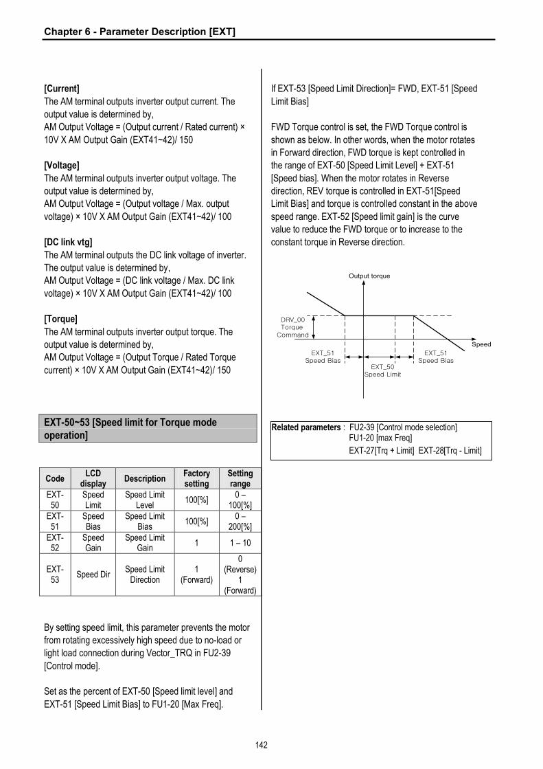
Chapter 6 - Parameter Description [EXT]
142
[Current]
The AM terminal outputs inverter output current. The
output value is determined by,
AM Output Voltage = (Output current / Rated current) ×
10V X AM Output Gain (EXT41~42)/ 150
[Voltage]
The AM terminal outputs inverter output voltage. The
output value is determined by,
AM Output Voltage = (Output voltage / Max. output
voltage) × 10V X AM Output Gain (EXT41~42)/ 100
[DC link vtg]
The AM terminal outputs the DC link voltage of inverter.
The output value is determined by,
AM Output Voltage = (DC link voltage / Max. DC link
voltage) × 10V X AM Output Gain (EXT41~42)/ 100
[Torque]
The AM terminal outputs inverter output torque. The
output value is determined by,
AM Output Voltage = (Output Torque / Rated Torque
current) × 10V X AM Output Gain (EXT41~42)/ 150
EXT-50~53 [Speed limit for Torque mode operation]
Code LCD
display Description
Factory setting
Setting range
EXT-50
Speed Limit
Speed Limit Level
100[%] 0 –
100[%] EXT-
51 Speed Bias
Speed Limit Bias
100[%] 0 –
200[%] EXT-
52 Speed Gain
Speed Limit Gain
1 1 – 10
EXT-53
Speed Dir Speed Limit
Direction 1
(Forward)
0 (Reverse)
1 (Forward)
By setting speed limit, this parameter prevents the motor
from rotating excessively high speed due to no-load or
light load connection during Vector_TRQ in FU2-39
[Control mode].
Set as the percent of EXT-50 [Speed limit level] and
EXT-51 [Speed Limit Bias] to FU1-20 [Max Freq].
If EXT-53 [Speed Limit Direction]= FWD, EXT-51 [Speed
Limit Bias]
FWD Torque control is set, the FWD Torque control is
shown as below. In other words, when the motor rotates
in Forward direction, FWD torque is kept controlled in
the range of EXT-50 [Speed Limit Level] + EXT-51
[Speed bias]. When the motor rotates in Reverse
direction, REV torque is controlled in EXT-51[Speed
Limit Bias] and torque is controlled constant in the above
speed range. EXT-52 [Speed limit gain] is the curve
value to reduce the FWD torque or to increase to the
constant torque in Reverse direction.
Speed
Output torque
EXT_51Speed Bias
DRV_00Torque
Command
EXT_51Speed Bias
EXT_50Speed Limit
Related parameters : FU2-39 [Control mode selection] FU1-20 [max Freq]
EXT-27[Trq + Limit] EXT-28[Trq - Limit]

Chapter 6 - Parameter Description [EXT]
143
The following illustrations show the relationship between torque, motor speed and speed limit direction.
Torque Dir. FWD REV
Speed limit direction
FWD REV
Torque change
SPD
Output TRQ
EXT_51SpeedBias
EXT_51SpeedBias
EXT-28Trq -Limit
EXT-27Trq +Limit
EXT-50SpeedLimit
SPD
Output TRQ
EXT-51SpeedBias
EXT-51SpeedBias
EXT-28Trq -Limit
EXT-27Trq +Limit
EXT-50SpeedLimit
Torque change
SPD
Output TRQ
EXT-51Speed Bias
EXT-51Speed Bias
EXT-28Trq -Limit
EXT-27Trq +Limit
EXT-50SpeedLimit
SPD
Output TRQ
EXT_51Speed Bias
EXT_51Speed Bias
EXT-28Trq -Limit
EXT-27Trq +Limit
EXT-50SpeedLimit

Chapter 6 - Parameter Description [EXT]
144
EXT-54: Zero Speed Detection Level EXT-55: Zero Speed Detection Bandwidth
Used to set the zero speed detection (SUB-B) l Only valid when FU2-39 [Control mode selection] is
set to Vector_SPD, Vector_TRQ. l Detect the zero speed using I/O-44 [Multi-function
auxiliary contact output selection]. Set Zspd Dect in I/O-44 [Multi-function auxiliary contact output] to activate this function.
☞ Note: Sub-board is needed to use multi-function
output terminal Q1, Q2, Q3.
Code Keypad Display
Parameter Name
Factory setting
Setting range
EXT-54
ZSD Level
Zero Speed Detection
Level 2 [Hz]
0 – 120
[Hz]
EXT-55
ZSD Band
Zero Speed Detection Bandwidth
1 [Hz] 0 – 5 [Hz]
Auxiliary contact relay activates as shown below if the following settings are applied to EXT-54 [Zero Speed Detection Level] and EXT-55 [Zero Speed Detection Bandwidth].
SPEED
AXA-AXC
Close
EXT-54ZSDLevel
EXT-55ZSDBand
EXT-54ZSD
Level
Close
EXT-56: Torque Detection Level EXT-57: Torque Detection Bandwidth
Use to set output torque detection (SUB-B) l Only valid when FU2-39 [Control mode selection] is
set to Vector_SPD, Vector_TRQ. l Detect Torque using I/O-44 [Multi-function auxiliary
contact output selection]. ☞ Note: Sub-board should be mounted to use multi-
function output terminal Q1, Q2, Q3.
EXT-56 [Torque Detection Level] and EXT-57 [Torque Detection Bandwidth] are activated in the following conditions as shown below.
TORQUE
AXA-AXC
EXT-56TD Level
EXT-57TD Band/
2
EXT-56TD Level
Close
Code Keypad Display
Description Factory setting
Setting range
EXT-56 TD Level Torque
Detection Level
100[%] 0 – 150 [%]
EXT-57 TD Band Torque
Detection Bandwidth
5[%] 0 – 10 [%]
Related Functions: FU2-39 [Control mode selection] I/O-44 [Multi-function auxiliary contact output]
Related Functions: FU2-39 [Control mode select] I/O-44 [Multi-function auxiliary contact output selection]

Chapter 6 - Parameter Description [APP]
145
6.6 Application Group [APP]
APP-00: Jump to desired code #
Jumping directly to any parameter code can be
accomplished by entering the desired code number. This
code is available only with LCD keypad.
APP-01: Application Mode Selection
This code sets the application mode.
Setting Range
LCD 7-Seg Description
None 0 Application mode is not selected.
Traverse 1 Traverse mode is selected in application group. Related functions (APP-02~07) are displayed.
MMC 2 MMC (Multi-Motor Control) mode is selected in application group. Related functions (APP-08~31) are displayed.
DRAW 3 DRAW mode is selected in application group. Related functions (APP-32~33) are displayed.
[Traverse]: This is a mechanism to wind thread to an
intended shape on a reel with a rotary motion and
reciprocation. Adjusting the speed of mechanical
reciprocation can make different shapes of thread reel.
The following figure shows an example. The guide
should move with low speed at the center of the reel and
fast at the edge of the reel.
[An example of Traverse Operation]
[Traverse Operation Pattern]
[MMC]: The ‘PID’ control should be selected in FU2-47
to use this function.
¨ One inverter can control multiple motors. This function
is often used when controlling the amount and pressure
of flow in fans or pumps. Built-in PI controller controls a
main motor after receiving process control value and
keeps the control value constant by connecting auxiliary
motors to commercial line when needed.
¨ In case that flow amount or flow pressure is beyond or
below the reference so the main drive cannot control by
itself, auxiliary motors are automatically turned on/off.
Maximum four (Q1~3 and Aux. output) auxiliary motors
can be run. Each Starting and Stop Frequency should
be set to four auxiliary motors.
¨ Auto Change can be selected to automatically switch
the order of the running motors for keeping motor run-
time constant. Set mode ‘1’ for automatic changing of
auxiliary motors only and set mode ‘2’ for automatic
changing of all motors including main motor. For mode
‘2’, external sequence (Refer to APP-26) should be
configured.
APP► Jump code 00 1
Factory Default: 1
APP► App. mode 01 None
0
01
Factory Default: None 0
Traverse Rotary Motion
Thread
Traverse Reciprocation (Mechanical)
Thread (Constant Speed)
APP-05 Traverse Dec
APP-03 Trv. Scr
APP-04 Traverse Acc
APP-06 Offset-High
APP-07 Offset-Low
Reference Speed
APP-02 Trv. Amp
Related Functions: APP-02 to APP-07 [Traverse Parameters] I/O-12 to I/O-14 [Multi-Function Input] EXT-30 to EXT-32 [Multi-Function Output]

Chapter 6 - Parameter Description [APP]
146
¨ Abnormal motor can be skipped from running by
using the multi-function input terminals (P1, P2, P3, and
P4). If a multi-function terminal is opened, the inverter
stops all running motors and restarts operation with only
normal motors except the abnormal motor. (Refer to
APP-29)
¨ Sleep function is initiated when flow demand is low.
Inverter stops motor when the motor runs below Sleep
Frequency (APP-24) during Sleep Delay Time (APP-23).
While in the sleep state, inverter keeps monitoring and
initiates Wake-Up function when the real value of the
controlling amount has decreased below the Wake-Up
level (APP-25).
☞ Note: Only one auxiliary motor can be connected with
AUX terminal on control terminal strip without using MMC
Option Board.
[MMC Diagram]
[Draw]: This is a kind of Open-Loop Tension Control.
This is used to maintain constant tension of material with
the speed difference between main motor and
subordinate motor.
APP-02: Traverse Amplitude
This code sets the frequency amplitude of traverse
operation. The value is the percentage of reference
frequency. The output value is determined by,
Trv. Amp Frequency = (Reference Freq. * Trv. Amp)/100
APP-03: Traverse Scramble Amplitude
This code sets the frequency amplitude of scramble
operation. The output value is determined by, Trv. Scr Frequency = (Trv. Amp Frequency * (100 - Trv. Scr))/100
APP-04: Traverse Accel Time APP-05: Traverse Decel Time
Sets the acceleration and deceleration time for traverse
operation.
APP►Trv. Amp[%]
02 0.0% 0.0
02
Factory Default: 0.0% 0.0
APP►Trv. Scr[%] 03 0.0%
0.0
03
Factory Default: 0.0% 0.0
APP►Trv Acc Time 04 2.0 sec 2.0
04
Factory Default: 2.0 sec 2.0
APP►Trv Dec Time 05 3.0 sec
3.0
05
Factory Default: 3.0 sec 3.0
Related Functions: APP-08 to APP-31 [MMC Parameters] DRV-04 [Frequency Mode] FU2-47 [PID Operation Selection] I/O-01 to I/O-10 [Analog Signal Input] EXT 15 to EXT21 [Pulse Input Signal] I/O-12 to I/O-14 [Multi-Function Input] EXT-30 to EXT-32 [Multi-Function Output]
Related Functions: APP-32 to APP-33 [Draw Parameters] DRV-04 [Frequency Mode] I/O-01 to I/O-10 [Analog Signal Input]
EXT 06 to EXT-10 [Analog Input Setting] I/O-12 to I/O-14 [Multi-Function Input] EXT-02 to EXT-04 [Multi-Function Input]
V1 V2
I
M1
M2
M3
M4 M
iS5
Input Power
Main Motor
Aux. Motor 4
Aux. Motor 3
Aux. Motor 2
Aux. Motor 1
MMC Board
AUX
RLY1
RLY2
RLY3

Chapter 6 - Parameter Description [APP]
147
☞ The ‘Trv Acc’ terminal set in EXT-30 to EXT-32 is ON
during traverse acceleration time. (Open Collector
Output)
☞ The ‘Trv Dec’ terminal set in EXT-30 to EXT-32 is ON
during traverse deceleration time. (Open Collector
Output)
☞ APP-04 and APP-05 should be set to a value less than
APP-03. If not, traverse control does not accomplished
correctly.
APP-06: Traverse Offset (Hi) Setting APP-07: Traverse Offset (Lo) Setting
This code makes positive offset during traverse
operation by multi-function input terminal. When the ‘Trv
Off Hi’ terminal is ON, the offset frequency is added to
the reference frequency. To use this function, set a
terminal out of multi-function input terminals (P1, P2, P3)
to ‘Trv Off Hi’ in I/O-12 ~ I/O-14. The offset value is
determined by,
Trv. Off Hi Frequency =(Reference Frequency * Trv. Off
Hi)/100
This code makes negative offset during traverse
operation by multi-function input terminal. When the ‘Trv
Off Lo’ terminal is ON, the offset frequency is subtracted
from the reference frequency. To use this function, set a
terminal out of multi-function input terminals (P1, P2, P3)
to ‘Trv Off Lo’ in I/O-12 ~ I/O-14. The offset value is
determined by,
Trv. Off Lo Frequency =(Reference Frequency * Trv. Off
Lo)/100
APP-08: Running Auxiliary Motor Number Display
This code shows how many auxiliary motors are running
by MMC control.
APP-09: Starting Auxiliary Motor Selection
This code sets the starting auxiliary motor for MMC
control.
APP-10: Operation Time Display on Auto Change
This code displays the operation time after Auto Change
is accomplished.
APP-11: Start Frequency of Aux. Motor 1 APP-12: Start Frequency of Aux. Motor 2 APP-13: Start Frequency of Aux. Motor 3 APP-14: Start Frequency of Aux. Motor 4
The inverter turns on AUX, RLY1, RLY2, and RLY3 in
APP► Trv Off Hi 06 0.0 %
0.0
06
Factory Default: 0.0 % 0.0
APP► Trv Off Lo
07 0.0 % 0.0
07
Factory Default: 0.0 % 0.0
APP►Aux Mot Run
08 0 0
08
Factory Default: 0 0
APP►Starting Aux
09 1 1
09
Factory Default: 1 1
APP►Auto Op Time
10 00:00 00:00
10
Factory Default: 00:00 00:00
APP►Start freq1 11 49.99 Hz
49.99
11
Factory Default: 49.99 Hz 49.99
APP►Start freq2
12 49.99 Hz 49.99
12
Factory Default: 49.99 Hz 49.99
APP►Start freq3 13 49.99 Hz
49.99
13
Factory Default: 49.99 Hz 49.99
APP►Start freq4 14 49.99 Hz
49.99
14
Factory Default: 49.99 Hz 49.99

Chapter 6 - Parameter Description [APP]
148
When the Flowincrese
When the Flowdecrease
Start
Stop
Aux. MotorStart/Stop
Frequency rise according toAPP-19
OutputFrequency
Aux start DT(APP-19)
Stop freq1(APP-15)
StartingFreq. Aux stop DT(APP-20)
Frequency drop according toAPP-20
Flow
Start freq 1(APP-11)
order if the output frequency is over the frequencies set
in APP-11 to APP-14, respectively, and the time is over
APP-19.
APP-15: Stop Frequency of Aux. Motor 1 APP-16: Stop Frequency of Aux. Motor 2 APP-17: Stop Frequency of Aux. Motor 3 APP-18: Stop Frequency of Aux. Motor 4
The inverter turns off RLY3, RLY2, RLY1, and AUX in
order if the output frequency is below the frequencies set
in APP-15 to APP-18, respectively, and the time is over
APP-20.
APP-19: Delay Time before Operating Aux. Motor APP-20: Delay Time before Stopping Aux. Motor
Sets the time the inverter waits before starting the
auxiliary motors.
Sets the time the inverter waits before stopping the
auxiliary motors.
[Aux. Motor Start/Stop with MMC]
APP-21: The Number of Aux. Motors
Sets the number of auxiliary motors connected to the
inverter.
APP-22: PID Bypass Selection
This is used to bypass the PID operation selected in
FU2-47. Select this code to ‘Yes’ when using MMC
function without PID control. The frequency is
determined by real value of control amount instead PID
controller output. The real value is also used as the
Start/Stop reference of Aux. motors.
The following figure shows the running pattern with this
function applied for controlling the flow rate of a tank. To
control the flow rate according to the water level of a
tank, divide the water level of the tank into the region to
the number of Aux. motors plus one, and map each
region from staring frequency to maximum frequency.
The inverter increases output frequency to lower the
water level in the tank when the water level in the tank
rises. When reaching maximum frequency, inverter
APP► Stop freq1 15 15.00 Hz
15.00
15
Factory Default: 15.00 Hz 15.00
APP► Stop freq2
16 15.00 Hz 15.00
16
Factory Default: 15.00 Hz 15.00
APP► Stop freq3 17 15.00 Hz
15.00
17
Factory Default: 15.00 Hz 15.00
APP► Stop freq4 18 15.00 Hz
15.00
18
Factory Default: 15.00 Hz 15.00
APP► Aux Start DT
19 60.0 sec 60.0
19
Factory Default: 60.0 sec 60.0
APP► Aux Stop DT
20 60.0 sec 60.0
20
Factory Default: 60.0 sec 60.0
APP►Nbr Aux’s 21 4
4
21
Factory Default: 4 4
APP►Regul Bypass 22 --- No ---
0
22
Factory Default: No 0

Chapter 6 - Parameter Description [APP]
149
connects aux. motors connected directly to commercial
line. After connecting aux. motor, inverter starts again
from the starting frequency. By selecting APP-22 to ‘Yes’,
PID operation is disabled and Control Mode (FU2-47) is
changed to ‘V/F’. PID Bypass is available only when
Freq. Mode (DRV-04) is set to ‘V1’, ‘1’ or ‘V2’. The level
in a tank can be checked in APP-30 [Actual Value] and
APP-31 [Actual Percent].
[Aux. Motor Start/Stop without PID Control]
APP-23: Sleep Delay Time APP-24: Sleep Frequency APP-25: Wake-Up Level
Sleep function is initiated when flow demand is low.
Inverter stops motor when the motor runs below Sleep
Frequency (APP-24) during Sleep Delay Time (APP-23).
While in the sleep state, inverter keeps monitoring and
initiates Wake-Up function when the real value of the
controlling amount has decreased below the Wake-Up
level (APP-25).
☞ Note: Sleep function is not operated if the Sleep Delay
Time (APP-23) is set to ‘0’.
[Sleep Operation]
APP-26: Auto Change Mode Selection
This function is used to change the running order of the
motors to regulate their run-time when multiple motors
are connected for MMC.
[0]: Not using Auto Change Function. The inverter keeps the order Main motor ⇒RLY1 ⇒
RLY2 ⇒ RLY3 ⇒ AUX and do not change the running
order of auxiliary motors.
[1]: Auto Change Function is applied only to aux. motors.
The inverter changes the order of auxiliary motors
except the main motor connected to the drive. Running order is Main Motor ⇒ RLY1 ⇒ RLY2 ⇒ RLY3 ⇒
AUX. And then it is changed to Main Motor ⇒ RLY2 ⇒
RLY3 ⇒ AUX ⇒ RLY1.
[2]: Auto Change Function is applied to all motors. The
inverter changes the order of all motors. The inverter
operates the initial motor and the others are directly
powered by commercial line. It should be used with
Inter-lock function after configuring external inter-lock
sequence circuit as shown below.
OutputFrequency
Max. Freq.
StartingFreq.
RUNSTOP
RUNSTOP
H-min H-max
Water Level ina Tank
Main Motor
Aux. Motor
APP► Sleep Delay 23 60.0 sec
60.0
23
Factory Default: 60.0 sec 60.0
APP► Sleep Freq 24 0.19 Hz
0.19
24
Factory Default: 0.19 Hz 0.19
APP► WakeUp level
25 35 % 35
25
Factory Default: 35 % 35
Actual Value
Time
Time
t<APP23
Sleep delay(APP23)
Stop Start
Wakeup level(APP25)
Sleep freq(APP24)
MainMotor
Output Frequency
APP► AutoCh_Mode 26 1
1
26
Factory Default: 1 1

Chapter 6 - Parameter Description [APP]
150
[Wiring Diagram for Inter-Lock Configuration]
[Sequence Circuit for Inter-Lock Configuration]
APP-27: Auto Change Time APP-28: Auto Change Level
This function is used to protect motor from running alone
for a long time by changing operation to other motor.
Auto Change is accomplished when the following
conditions are satisfied:
1) The time set in APP-27 is over.
2) The actual value of controlling amount is less than the
value set in APP-28.
3) Only one motor is running.
When above three conditions are met, the inverter stops
the running motor, and changes motor to run by the
order set in APP-26. and then continues operation
according to new order.
If Auto Change Level (APP-28) is set to ‘0’, the function
is initiated only when the motor is in Stop or Sleep state.
The count time for Auto Change is depend on Auto
Change Mode (APP-26). In mode ‘0’, inverter starts
counting only when auxiliary motor is running. In mode
‘1’ or ‘2’, inverter starts counting when any motor is
running including main motor.
APP-29: Inter-Lock Selection
By setting this code to ‘Yes’, the multi-function input
terminals (P1 ~ P4) are used as auxiliary motor
operating condition of RLY1, RLY2, RLY3, and AUX.
The multi-function input terminal should be turned on to
run the corresponding auxiliary motor. If running with
any multi-function input terminal open with this function,
the inverter starts motors except the corresponding
motor. If multi-function input happens to be turned off
during motor running, the inverter stops all running
motors and restarts running with only normal motors
except the subject motor. By setting this parameter to
‘Yes’, the multi-function input terminals (P1~P4) are set
to ‘Interlock1’ through ‘Interlock4’ automatically.
☞ Note: P1 through P4 cannot be used for other purpose it
this code is set to ‘Yes’.
3 Phase Input
K1
K1.1
K2
K2.2
U V W
R S T
iS5
M1 M
2
230VAC
SV-iS5
M1/iS5 M2/iS5 M1/main
K1 K1.1 K2 K2.1
K2.1
K1 K1
K1
K2 K2
K2 K1.1
Auto Auto Main Main
RLY RLYP1 P2 CM
S1 S2
APP► AutoEx-intv
27 72:00 72:00
27
Factory Default: 72:00 72:00
APP► AutoEx-level 28 20 %
20
28
Factory Default: 20 % 20
APP► Inter-lock 29 --- No ---
0
29
Factory Default: No 0
Related Functions: I/O-12 to I/O-14 [Multi-Function Input] EXT-02 to EXT-04 [Multi-Function Input]
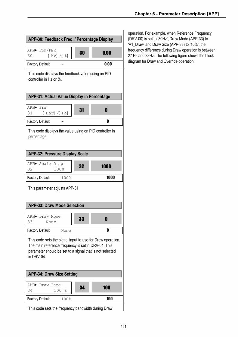
Chapter 6 - Parameter Description [APP]
151
APP-30: Feedback Freq. / Percentage Display
This code displays the feedback value using on PID
controller in Hz or %.
APP-31: Actual Value Display in Percentage
This code displays the value using on PID controller in
percentage.
APP-32: Pressure Display Scale
This parameter adjusts APP-31.
APP-33: Draw Mode Selection
This code sets the signal input to use for Draw operation.
The main reference frequency is set in DRV-04. This
parameter should be set to a signal that is not selected
in DRV-04.
APP-34: Draw Size Setting
This code sets the frequency bandwidth during Draw
operation. For example, when Reference Frequency
(DRV-00) is set to ‘30Hz’, Draw Mode (APP-33) to
‘V1_Draw’ and Draw Size (APP-33) to ‘10%’, the
frequency difference during Draw operation is between
27 Hz and 33Hz. The following figure shows the block
diagram for Draw and Override operation.
APP► Fbk/PER 30 [Hz]/[%]
0.00
30
Factory Default: - 0.00
APP► Prs
31 [Bar]/[Pa] 0
31
Factory Default: - 0
APP► Draw Mode 33 None
0
33
Factory Default: None 0
APP► Draw Perc
34 100 % 100
34
Factory Default: 100% 100
APP► Scale Disp
32 1000 1000
32
Factory Default: 1000 1000
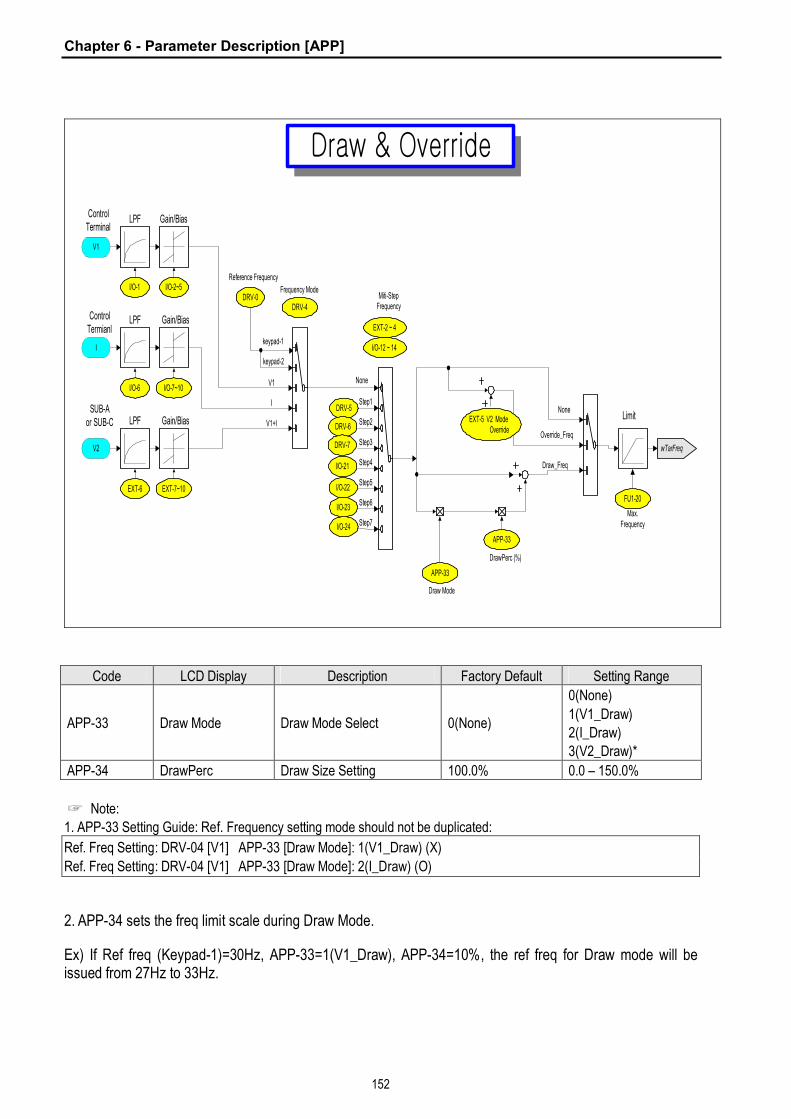
Chapter 6 - Parameter Description [APP]
152
Draw & Override
Gain/Bias
I/O-2~5
DRV-5
DRV-6
I/O-1DRV-0
DRV-4
Frequency Mode
Reference Frequency
Miti-StepFrequency
I/O-12 ~ 14
LPF
Step2
V1
ControlTerminal
EXT-2 ~ 4
DRV-7
I/O-21
I/O-22
I/O-23
I/O-24
keypad-1
keypad-2
Gain/Bias
I/O-7~10I/O-6
LPF
I
ControlTermianl
V1
SUB-Aor SUB-C Gain/Bias
EXT-7~10EXT-6
LPF
V2
None
I
V1+I
FU1-20
Max.Frequency
Limit
wTarFreq
None
APP-33
DrawPerc (%)
Override_Freq
Draw_Freq
EXT-5 V2 Mode Override
Step1
Step3
Step4
Step5
Step6
Step7
APP-33
Draw Mode
Code LCD Display Description Factory Default Setting Range
APP-33 Draw Mode Draw Mode Select 0(None)
0(None)
1(V1_Draw)
2(I_Draw)
3(V2_Draw)*
APP-34 DrawPerc Draw Size Setting 100.0% 0.0 – 150.0%
☞ Note:
1. APP-33 Setting Guide: Ref. Frequency setting mode should not be duplicated:
Ref. Freq Setting: DRV-04 [V1] APP-33 [Draw Mode]: 1(V1_Draw) (X)
Ref. Freq Setting: DRV-04 [V1] APP-33 [Draw Mode]: 2(I_Draw) (O)
2. APP-34 sets the freq limit scale during Draw Mode.
Ex) If Ref freq (Keypad-1)=30Hz, APP-33=1(V1_Draw), APP-34=10%, the ref freq for Draw mode will be issued from 27Hz to 33Hz.

153
CHAPTER 7 - OPTIONS
The iS5 series inverter provides many options for various applications. See the following option table and select the
proper options according to your application.
Option Name Description
Sub-A Board
(Extended I/O)
¨ Extended I/O Module
¨ Three Multi-Function Inputs (P4, P5, P6)
¨ Three Multi-Function Outputs (Q1, Q2, Q3)
¨ Auxiliary Analog Frequency Reference (V2)
¨ LM (Load Meter) Output (0 ~ 10V)
Sub-B Board
(Speed Feedback)
¨ Encoder Pulse Input – Speed Feedback (AOC, BOC / A+, A-, B+, B-)
¨ Encoder Pulse Output (FBA, FBB)
¨ Vector control (PG operation) and reference freq via pulse input
Sub-C Board
(Extended I/O)
¨ Extended I/O Module
¨ Three Multi-Function Inputs (P4, P5, P6)
¨ One Multi-Function Outputs (Q1)
¨ Isolated Auxiliary Analog Frequency Reference (V2)
¨ Two Isolated Analog Meter Output (AM1, AM2)
PLC Communication
(F-Net)
¨ Connection with Fnet Communication Module for GLOFA PLC
¨ Inverter Connection: Max. 64
¨ Baud Rate: 1M bps
Inte
rnal
Inst
alla
tion
Sub Boards
RS-485
¨ RS-485 Communication
¨ Inverter Connection: Max. 32
¨ Baud Rate: Max. 19200 bps
LCD ¨ 32-Character Display
¨ Download and Upload from the Keypad Keypad
7-Segment ¨ Six Digit 7-Sengment Display
Remote
Cable Remote Cable ¨ 2m, 3m, 5m long keypad cables for separate keypad installation
DB Resistor ¨ Enables Inverter to decelerate rapidly. Ext
erna
l Ins
talla
tion
Dynamic
Braking DB Unit ¨ DB units are provided as an option for 40 ~ 100 HP inverters.
☞ Note: Refer to option manual for more details.

Chapter 7 - Options
154
The following table shows the Sub-Board Selection Guide according to Functions.
Sub-Board Type Code Function Description
SUB-A Board SUB-B Board SUB-C Board
EXT-02 Multi-Function Input Terminal ‘P4’ √ √
EXT-03 Multi-Function Input Terminal ‘P5’ √ √
EXT-04 Multi-Function Input Terminal ‘P6’ √ √
EXT-05 V2 Mode Selection √ √
EXT-06 Filtering Time Constant for V2 Input Signal √ √
EXT-07 V2 Input Minimum Voltage √ √
EXT-08 Frequency Corresponding to V2 Input Minimum Voltage √ √
EXT-09 V2 Input Maximum Voltage √ √
EXT-10 Frequency Corresponding to V2 Input Maximum Voltage √ √
EXT-14 Usage for Pulse Input Signal √
EXT-15 Pulse Input Signal Selection √
EXT-16 Encoder Pulse Selection √
EXT-17 Filtering Time Constant for Pulse Input Signal √
EXT-18 Pulse Input Minimum Frequency √
EXT-19 Frequency Output corresponding to Pulse Input Minimum
Frequency √
EXT-20 Pulse Input Maximum Frequency √
EXT-21 Frequency Output corresponding to Pulse Input Maximum
Frequency √
EXT-22 P-Gain for PG Option √
EXT-23 I-Gain for PG Option √
EXT-24 Slip Frequency for PG Option √
EXT-25 P-Gain for (Sensored) Vector_SPD
EXT-26 I-Gain for (Sensored) Vector_SPD
EXT-27 Forward Torque Limit
EXT-28 Reverse Torque Limit
EXT-30 Multi-function Output Terminal ‘Q1’ √ √
EXT-31 Multi-function Output Terminal ‘Q2’ √
EXT-32 Multi-function Output Terminal ‘Q3’ √
EXT-34 LM (Load Meter) Output Selection √
EXT-35 LM Output Adjustment √
EXT-40 AM1 (Analog Meter 1) Output Selection √
EXT-41 AM1 Output Adjustment √
EXT-42 AM2 (Analog Meter 2) Output Selection √
EXT-43 AM2 Output Adjustment √

Chapter 7 - Options
155
7.1 Sub-A board
7.1.1 Board configuration
3 P230/460 V50/60 Hz
IM
U
VW
E
R
S
T+FM
5G
30A
30B
30C
AXA
AXC
Multi-function output relay
VR
V1
I
5G
(0-10V, 1 kohm)
Common for VR,V1,I
3. Three types of External speed signal input available. (V, I, V+I, Refer to Parameter list and description for more details)
NFB MC
24 V
CM
LM
P4
P5
P6
Q1
Q2
Q3
EXTG
VR
V2
5G
XCEL-L
Multi-functioninput
Commonterminal for
Multi-functioninput & LM
Common terminal for multi-function output Q1, Q2, Q3
FDT -1
FDT -2
FDT -3
+
Sub - ABoard
FM
LM
XCEL-M
XCEL-H
Factory setting
Common Terminal
Forward Run / Stop
Emergency stop
Fault reset
Jog
Multi-function input 1
Multi-function input 2
Multi-function input 3
FX
RX
BX
RST
JOG
P2
P3
P1
CM
Output freq *2
Analog Meter
0-10V, 1mA
*2Output freqAnalog Meter
Potentiometer1 kohm, 1/2W
Fault output relay
Less than AC 250V,1ALess than DC 30V, 1A
Less than AC 250V,1ALess than DC 30V, 1AFactory setting: 'Run'
Power supply forspeed signal
(+12V 10mA)
Speed signal input
4-20mA (250 ohm)
Speed signal input
Speed signal input *3
Note) 1. : Main circuit : Control circuit2. Output voltage is adjustable up to 12V.
.
I/O-12~14:Factory setting:Multi-speed input(Speed-L,M,H)
Reverse Run / Stop
1 k ohm,1/2W
Potentiometer
Power supply for V2 (+12V 10mA)
Voltage input 0-10V(1kohm)
Multi-functionoutput
Maximumcurrent thruPC: 5mA
0-10V, 1mA

Chapter 7 - Options
156
7.1.2 Terminal Configuration
VR V2 5G NC Q1 Q2 Q3 EXTG NC P4 P5 P6 LM CM
7.1.3 Terminal Description
Section Terminal Name Description
P4, P5, P6 Multi-Function Input Used as the extended function of P1, P2, P3
(I/O-12 ~ I/O-14) Contact Input
CM Common Terminal Common terminal for P4, P5, P6
VR Power Supply for V2 DC voltage output terminal for V2 (+12V, 10mA)
V2 Analog Voltage Input Analog voltage input terminal for frequency reference or override.
Inpu
t
Analog
Frequency
Reference 5G Common Terminal Common terminal for VR and V2
LM Load Meter
Used to monitor one of Output Frequency, Output Current, Output
Voltage, DC link Voltage.
(+15V Pulse output, Average voltage: 0 ~ 10V DC)
+15V Pulse
Output
CM Common Terminal Common terminal for LM
Q1, Q2, Q3 Multi-Function Output
(Open-Collector Output) Used as the extended function of AXA, AXC (I/O-44)
Out
put
Open Collector
Output EXTG External Common Terminal Common terminal for Q1, Q2, Q3
NC Not Used
7.1.4 Parameters of Sub-A Board
Code Parameter Description Code Parameter Description
EXT-01 Sub Board Type Display EXT-09
EXT-02 EXT-10 Analog Voltage Input Signal (V2) Adjustment
EXT-03 EXT-30
EXT-04
Multi-Function Input Terminal (P4, P4, P6) Define
EXT-31
EXT-05 V2 Mode Selection EXT-32
Multi-Function Output Terminal (Q1, Q2, Q3)
Define
EXT-06 Filtering Time Constant for V2 Input Signal EXT-34
EXT-07 EXT-35 LM Output Adjustment
EXT-08 Analog Voltage Input Signal (V2) Adjustment
+24V DC
24V Ground
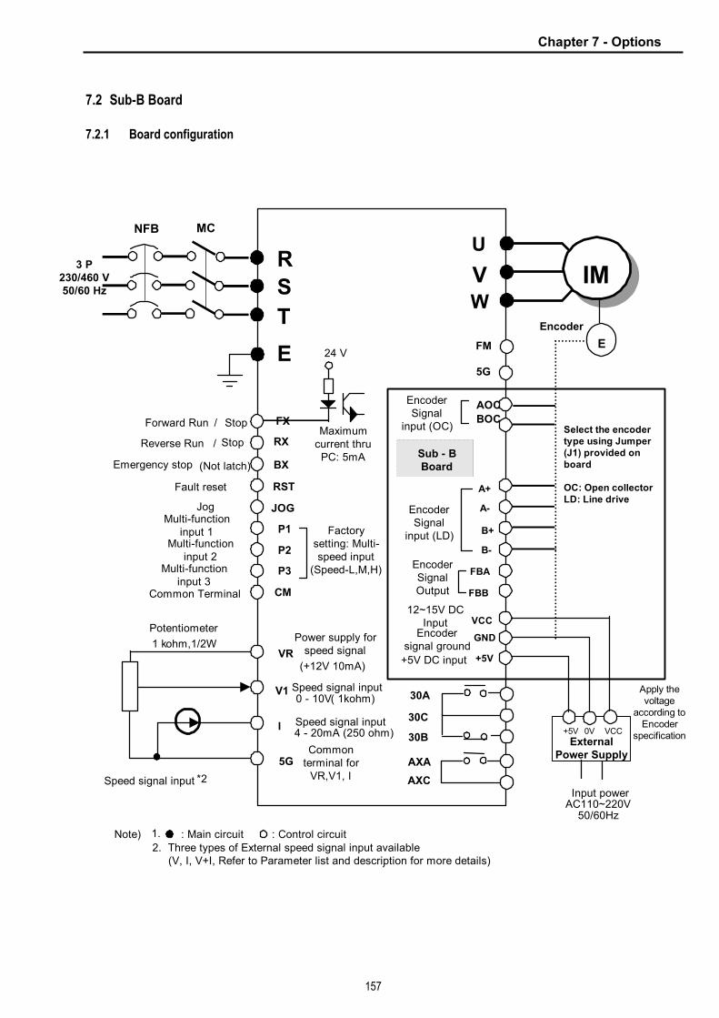
Chapter 7 - Options
157
7.2 Sub-B Board
7.2.1 Board configuration
3 P230/460 V50/60 Hz
IM
U
VW
E
R
S
T
FX
RX
BX
RST
JOG
P2
P3
FM
5G
30A
30B
30C
AXA
AXC
P1
VR
V1
I
5G
Speed signal input0 - 10V( 1kohm)
4 - 20mA (250 ohm)
1 kohm,1/2W
Speed signal input *2
Commonterminal for
VR,V1, I
CM
NFB MC
24 V
A-
A+
B+
B-
FBA
FBB
VCC
GND
BOC
EncoderSignal
input (OC)
0
EncoderSignalOutput
Encodersignal ground
Sub - BBoard
Apply thevoltage
according toEncoder
specificationExternal
Power Supply
E
Encoder
Input powerAC110~220V
50/60Hz
12~15V DCInput
+5V
+5V
Common Terminal
Potentiometer
Reverse Run /
Forward Run / Stop
Emergency stop (Not latch)
Fault reset
JogMulti-function
input 1
Stop
Multi-functioninput 2
Multi-functioninput 3
0V VCC
Power supply forspeed signal
(+12V 10mA)
Speed signal input
Factorysetting: Multi-speed input
(Speed-L,M,H)
Select the encodertype using Jumper(J1) provided onboard
OC: Open collectorLD: Line drive
EncoderSignal
input (LD)
+5V DC input
AOC
Note) 1. : Main circuit : Control circuit 2. Three types of External speed signal input available (V, I, V+I, Refer to Parameter list and description for more details).
Maximumcurrent thru
PC: 5mA

Chapter 7 - Options
158
7.2.2 Terminal Configuration (total 14 pins)
AOC BOC A+ A- B+ B- FBA FBB GND GND +5V +5V VCC VCC
7.2.3 Terminal Description
Section Terminal Name Description
AOC A Pulse Input Terminal Connects A signal of Open Collector type encoder. Open
Collector
Type BOC B Pulse Input Terminal Connects B signal of Open Collector type encoder.
A+ A+ Pulse Input Terminal Connects A+ signal of Line Drive type encoder.
A- A- Pulse Input Terminal Connects A- signal of Line Drive type encoder.
B+ B+ Pulse Input Terminal Connects B+ signal of Line Drive type encoder.
Encoder
Signal
Input Line Drive
Type
B- B- Pulse Input Terminal Connects B- signal of Line Drive type encoder.
FBA Encoder A Pulse Output Outputs A signal received from the encoder. Signal
Output
Encoder
Signal
Output FBB Encoder B Pulse Output Outputs B signal received from the encoder.
+5V +5V DC Input Terminal
(For Line Drive type)
Provides +5V DC power output to encoder.
(5V DC, Minimum 0.5A)
VCC
+12 to 15V DC Input/output
Terminal from External Power
Supply to Encoder
(For Open collector type)
Encoder supply voltage, Supply proper voltage according to the
encoder specification.
(+12 to 15V DC, Minimum 0.5A)
Power Supply Input
GND Ground Terminal Ground for Power supply and encoder signal.
7.2.4 Parameters of Sub-B Board
Code Parameter Description Code Parameter Description
EXT-01 Sub Board Type Display EXT-21 Pulse Input Signal Adjustment
EXT-14 Usage for Pulse Input Signal EXT-22 P-Gain
EXT-15 Pulse Input Signal Selection EXT-23 I-Gain
EXT-16 Encoder Pulse Number EXT-24 Slip Frequency
EXT-17 Filtering Time Constant EXT-25 P-Gain for (Sensored) Vector_SPD
EXT-18 EXT-26 I-Gain for (Sensored) Vector_SPD
EXT-19 EXT-27 Forward Torque Limit
EXT-20
Pulse Input Signal Adjustment
EXT-28 Reverse Torque Limit

Chapter 7 - Options
159
AOC
R
S
T
G
U
V
W
FX
RX
BX
RST
JOG
P1
P2
P3
CM
VR
V1
5G
IM
Motor
3phase
ACinput
BOC
A+
A-
B+
B-
FBA
FBB
GND
EEncoder
GND
+5V
+5V
VCC
VCC
Sub-B
MCNFC
FWD Run/Stop
REV Run/Stop
Emergency stop
Fault reset
JOG
I
Potentiometer1 kohm, 1/2W
24 V
FM
5G
30A
30C
30B
AXA
AXC
Encodersignal
(LD) input
Encodersignaloutput
Encodersignal
ground
Note) 1. : Main circuit, : Control circuit. 2. External speed signal: V1, I, V1+I (Refer to Parameter list)
Shield
+5 V poweroutput toEncoder
1. Sub-B board with Line Drive type encoder
I/O-12~14 :Factory setting:
Multi-speed input(Speed-L, M, H)
Common Terminal
Multi-functioninput 1
Multi-functioninput 2
Multi-functioninput 3
Power supply forspeed signal+12V 10mASpeed signal input0~10V(1 kohm)
Speed signal input4~20mA (250ohm)
(Common forVR, V1, I )
Maximumcurrent thruPC: 5mA

Chapter 7 - Options
160
AOC
R
S
T
G
U
V
W
FX
RX
BX
RST
JOG
P1
P2
P3
CM
VR
V1
5G
IM
3phase
ACinput
BOC
A+
A-
B+
B-
FBA
FBB
GND
EEncoder
GND
+5V
+5V
VCC
VCC
Sub-B
MCNFC
FWD Run/Stop
REV Run/Stop
Emergency stop
Fault reset
JOG
Multi-functioninput 1
Common Terminal
I
Power supply forspeed signal+12V 10mASpeed signal input0~10V(1 kohm)
Speed signal input4~20mA (250ohm)
(Common forVR, V1, I )
Potentiometer1 kohm, 1/2W
I/O-12~14 :Factory setting:
Multi-speed input(Speed-L, M, H)
24 V
FM
5G
30A
30C
30B
AXA
AXC
Encoder signalinput(Open collector)
Encodersignaloutput
12~15 V DCinput/output
terminal
Encodersignal ground
Note) 1. : Main circuit, : Control circuit 2. External speed command: V1, I, and V1+I (Refer to Function list)
Shield
ExternalPowerSupply
2. Sub-B board with Open collector type encoder
Multi-functioninput 2
Multi-functioninput 3
Maximumcurrent thru
PC: 5mA
*2

Chapter 7 - Options
161
7.3 Sub-C Board (Isolated)
7.3.1 Board Configuration
3P230/460 V50/60 Hz
IM
U
VW
E
R
S
T
FX
RX
BX
RST
JOG
P2
P3
+FM
5G
30A
30B
30C
AXA
AXC
Output freqanalog meter(0-10V, 1mA)
*2
P1
Fault output relayLess than AC 250V, 1ALess than DC 30V, 1A
VR
V1
I
5G
0- 10V(1 kohm)
*3
Maximumcurrent thruPC: 5mA
CM
NFB MC
24 V
AM2
AM1
P4
P5
P6
Q1
EXTG
VR
V2
GND
XCEL-LMulti-function
input
Open collectorMulti-function
input (Less than25V, 50mA)
FDT-1
Analog meter output 1(0-10V, 1mA)
Sub- CBoard
FM
CM
FWD Run/Stop
REV Run/Stop
Fault reset
JOG
Multi-function input 1
Common Terminal
Multi-function input 2
Multi-function input 3
Emergency brake
Note) 1. : Main circuit : Control circuit
2. Output voltage is adjustable up to 12V
3. Three types of External speed signal input available (V, I, V+I, Refer to Parameter list and description for more details)
.
4 - 20mA (250 ohm)
Speed signal input
Commonterminal forVR,V1, I
Power supply forspeed signal(+12V 10mA)
Speed signal input
Factory setting:Multi-speed
input(Speed-L,M,H)
Potentiometer1kohm, 1/2W
Potentiometer1kohm, 1/2W
Speed signal input
Analog meter output 2(0-10V, 1mA)
XCEL-M
XCEL-H
Common terminalfor P4-6
Common terminalfor Q1
Multi-function output relayLess than AC 250V, 1ALess than DC 30V, 1AFactory setting:'Run'
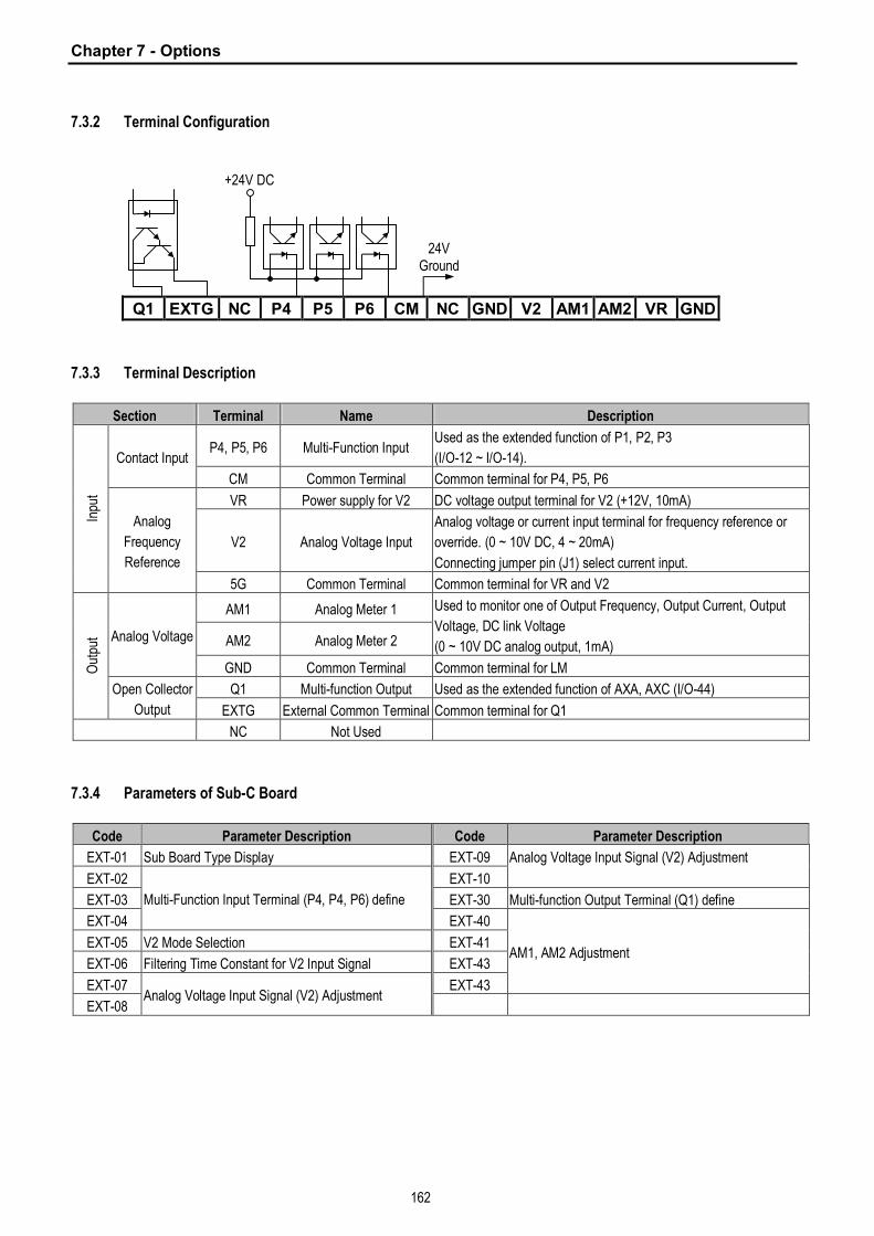
Chapter 7 - Options
162
7.3.2 Terminal Configuration
Q1 EXTG NC P4 P5 P6 CM NC GND V2 AM1 AM2 VR GND
7.3.3 Terminal Description
Section Terminal Name Description
P4, P5, P6 Multi-Function Input Used as the extended function of P1, P2, P3
(I/O-12 ~ I/O-14). Contact Input
CM Common Terminal Common terminal for P4, P5, P6
VR Power supply for V2 DC voltage output terminal for V2 (+12V, 10mA)
V2 Analog Voltage Input
Analog voltage or current input terminal for frequency reference or
override. (0 ~ 10V DC, 4 ~ 20mA)
Connecting jumper pin (J1) select current input.
Inpu
t
Analog
Frequency
Reference
5G Common Terminal Common terminal for VR and V2
AM1 Analog Meter 1
AM2 Analog Meter 2
Used to monitor one of Output Frequency, Output Current, Output
Voltage, DC link Voltage
(0 ~ 10V DC analog output, 1mA) Analog Voltage
GND Common Terminal Common terminal for LM
Q1 Multi-function Output Used as the extended function of AXA, AXC (I/O-44)
Out
put
Open Collector
Output EXTG External Common Terminal Common terminal for Q1
NC Not Used
7.3.4 Parameters of Sub-C Board
Code Parameter Description Code Parameter Description
EXT-01 Sub Board Type Display EXT-09
EXT-02 EXT-10
Analog Voltage Input Signal (V2) Adjustment
EXT-03 EXT-30 Multi-function Output Terminal (Q1) define
EXT-04
Multi-Function Input Terminal (P4, P4, P6) define
EXT-40
EXT-05 V2 Mode Selection EXT-41
EXT-06 Filtering Time Constant for V2 Input Signal EXT-43
EXT-07 EXT-43
AM1, AM2 Adjustment
EXT-08 Analog Voltage Input Signal (V2) Adjustment
+24V DC
24V Ground
Chapter 7 - Options
163
7.4 Communication option boards
7.4.1 F-Net (Needed for Communication with LS GLOFA PLC)
Open network system protocol based on IEC/ISA FieldBus ² Specification l Topology: Linear Bus Topology l Band Method: Baseband l Protocol: Fnet Protocol l Media Access Method: Token l Drive link: Fiber optics l Number of nodes: up to 64 nodes/Bus l Max. Data transmission size: 256byte l Baud rate: 1Mbps l Transmission distance: 750m Max. l Error check: CRC-16 l Encoding method: Menchester Biphase-L l Station: 0 – 63 (Setting via Keypad. Dip-switch not provided)
7.4.2 Device-Net (Field bus)
² Features l Topology: Linear Bus Topology l Band Method: Baseband l Protocol: DeviceNet Protocol l Media Access Method: CSMA/CD-NBA l (Carrier Sense Multiple Access / Collision Detection – Nondestructive Bitwise Arbitration) l Drive link: 5-wire Cable (Twisted Pair) l Number of nodes: 64 nodes/Bus Max l Max. Data transmission size: max 8 bytes (64bits) l Data rates and Max. Cable length (thick): 125kbps (500m/1640ft), 250kbps (250m/820ft), 500kbps
(100m/328ft) ² Specification l Device type: AC Drive l Communication control method:
① Explicit Peer to Peer Messaging ② Master/Scanner (Predefined M/S Connection) ③ I/O Slave Messaging: Polling Connection
l Baud rate: 125kbps, 250kbps, 500kbps l Supply voltage: 11 - 25V l Faulted Node Recovery l Station: 0 – 63 (Setting via Keypad, Dip-switch not provided) l Output Assembly Instance: 20, 21(100, 101 vendor specific) l Input Assembly Instance: 70, 71(110, 111 vendor specific) l Open Style Connector l Interface: DPRAM l Supports EDS files
* Refer to communication option manuals for details.

Chapter 7 - Options
164
7.4.3 RS485 & MODBUS-RTU Communication [Performance Specification]
Category Specification
Communication Method RS485 (RS232-485 Converter)
Transmission Form Bus method Multi-drop Link System Applicable Inverter SV-iS5 series Converter Converter equipped with RS232 Number of connectable Inverter 31, Max. Transmission Distance Max. 1200m (Within 700m is desired)
[Hardware Specification]
Category Specification
Installation Install on the Control Board of Inverter using option connector (CN2) Control Board Powered by Inverter Power
Supply Communication Board Powered by Control Board Power (Isolated Power) [Communication Specification]
Category Specification
Communication Speed 19200/9600/4800/2400/19200 bps User Selectable Control Procedure Asynchronous Communication System Communication System Half duplex system Character System ASCII (8 bit) Stop Bit Length 1 bit Error Check (CRC16) 2 byte Parity check None
7.4.4 12Bit Binary (DI) Input Category Specification
BIT Digital 12Bit input Communication Install on the Control Board of Inverter using option connector (CN2)
Control Board Powered by Inverter Power Supply 24V Power Powered by Inverter 24V using connector
7.4.5 Installing Option Board
Connect the option board to Control board using Connector CN2.
CN2
Connector
Mounting
poles
Option board Control board
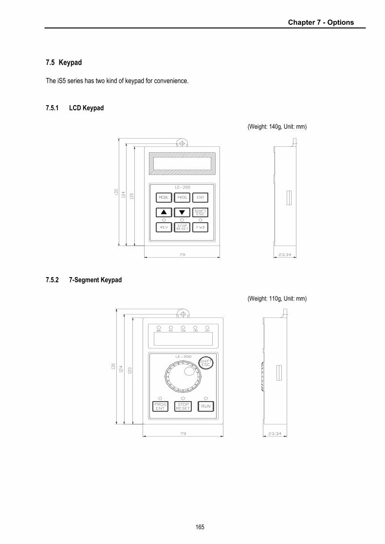
Chapter 7 - Options
165
7.5 Keypad
The iS5 series has two kind of keypad for convenience.
7.5.1 LCD Keypad
(Weight: 140g, Unit: mm)
7.5.2 7-Segment Keypad
(Weight: 110g, Unit: mm)
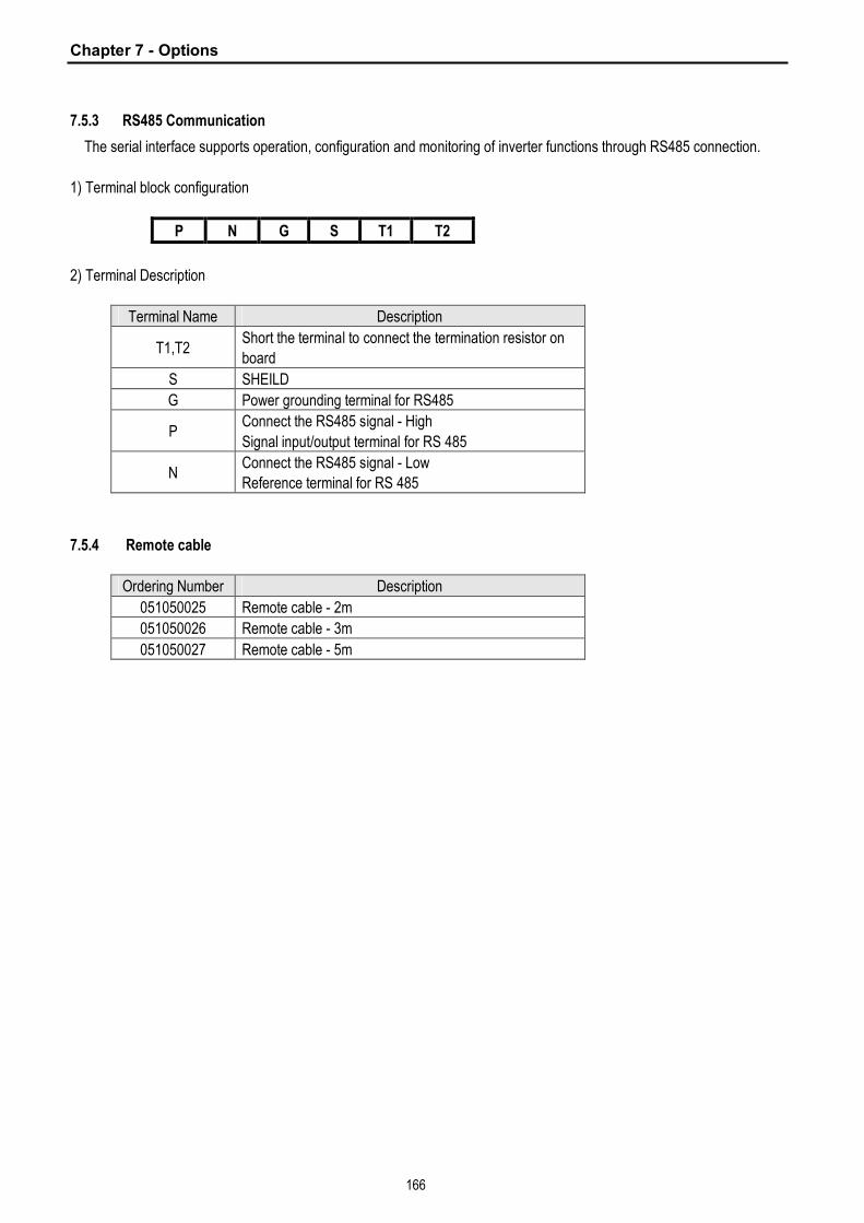
Chapter 7 - Options
166
7.5.3 RS485 Communication
The serial interface supports operation, configuration and monitoring of inverter functions through RS485 connection.
1) Terminal block configuration
P N G S T1 T2
2) Terminal Description
Terminal Name Description
T1,T2 Short the terminal to connect the termination resistor on
board
S SHEILD
G Power grounding terminal for RS485
P Connect the RS485 signal - High
Signal input/output terminal for RS 485
N Connect the RS485 signal - Low
Reference terminal for RS 485
7.5.4 Remote cable
Ordering Number Description
051050025 Remote cable - 2m
051050026 Remote cable - 3m
051050027 Remote cable - 5m

Chapter 7 - Options
167
7.6 DB Resistors
1) Internal DB Resistor
SV-iS5 inverters up to 3.7kW have built-in DB resistor on Power stack as factory installation. Installing the external
DB resistor (Optional) kit is strongly recommended when the unit is used for continuous operation or motor rating
is above 3.7kW.
Voltage Applied motor
capacity (kW/HP)
Operating rate
(%ED/Continuous Braking Time)
Built in DB resistor
(Braking Torque: 100%)
0.75 / 1 3%/ 5Sec 200 ohm, 100W
1.5 / 2 3% / 5 Sec 100 ohm, 100W
2.2 / 3 2% / 5 Sec 60 ohm, 100W 200V Class
3.7 / 5 2% / 5 Sec 40 ohm, 100W
0.75 / 1 3% / 5 Sec 900 ohm, 100W
1.5 / 2 3% / 5 Sec 450 ohm, 100W
2.2 / 3 2% / 5 Sec 300 ohm, 100W 400V Class
3.7 / 5 2% / 5 Sec 200 ohm, 100W

Chapter 7 - Options
168
2) DB Resistor (For External Installation, Optional)
DB transistor is integrated for ratings below 7.5kW. Install the external DB resistor if necessary. However, DB
transistor is not provided for the ratings above 11kW, installing both external DB unit and DB resistor are required.
See the following table for more details (ED: 5%, Continuous Braking Time: 15 sec). If Enable duty (%ED) is
increased to 10%, use the external DB resistor having twice Wattage rating.
100 % Braking Torque 150% Braking Torque
Applied motor
capacity
(kW / HP)
Operating rate
(ED/Continuous
Braking Time) [ohm] [W] Type [ohm] [W] Type
0.75 / 1 5% / 15 Sec 200 100 TYPE 1 150 150 TYPE 1
1.5 / 2 5% / 15 Sec 100 200 TYPE 1 60 300 TYPE 1
2.2 / 3 5% / 15 Sec 60 300 TYPE 1 50 400 TYPE 1
3.7 / 5 5% / 15 Sec 40 500 TYPE 2 33 600 TYPE 2
5.5 / 7.5 5% / 15 Sec 30 700 TYPE 3 20 800 TYPE 3
7.5 / 10 5% / 15 Sec 20 1000 TYPE 3 15 1200 TYPE 3
11 / 15 5% / 15 Sec 15 1400 TYPE 3 10 2400 TYPE 3
15 / 20 5% / 15 Sec 11 2000 TYPE 3 8 2400 TYPE 3
18.5 / 25 5% / 15 Sec 9 2400 TYPE 3 5 3600 TYPE 3
22 / 30 5% / 15 Sec 8 2800 TYPE 3 5 3600 TYPE 3
30 / 40 10% / 6 Sec 4.2 6400 - - - -
37 / 50 10% / 6 Sec 4.2 6400 - - - -
45 / 60 10% / 6 Sec 2.8 9600 - - - -
2
0
0
V
55 / 75 10% / 6 Sec 2.8 9600 - - - -
0.75 / 1 5% / 15 Sec 900 100 TYPE 1 600 150 TYPE 1
1.5 / 2 5% / 15 Sec 450 200 TYPE 1 300 300 TYPE 1
2.2 / 3 5% / 15 Sec 300 300 TYPE 1 200 400 TYPE 1
3.7 / 5 5% / 15 Sec 200 500 TYPE 2 130 600 TYPE 2
5.5 / 7.5 5% / 15 Sec 120 700 TYPE 3 85 1000 TYPE 3
7.5 / 10 5% / 15 Sec 90 1000 TYPE 3 60 1200 TYPE 3
11 / 15 5% / 15 Sec 60 1400 TYPE 3 40 2000 TYPE 3
15 / 20 5% / 15 Sec 45 2000 TYPE 3 30 2400 TYPE 3
18.5 / 25 5% / 15 Sec 35 2400 TYPE 3 20 3600 TYPE 3
22 / 30 5% / 15 Sec 30 2800 TYPE 3 20 3600 TYPE 3
30 / 40 10% / 6 Sec 16.9 6400 - - - -
37 / 50 10% / 6 Sec 16.9 6400 - - - -
45 / 60 10% / 6 Sec 11.4 9600 - - - -
55 / 75 10% / 6 Sec 11.4 9600 - - - -
4
0
0
V
75 / 100 10% / 6 Sec 8.4 12800 - - - -

Chapter 7 - Options
169
3) DB Resistor Wiring
When wiring, connect the DB Resistor as SHORT as possible.
· DB resistor wiring for 1 – 5 HP Inverter
DB resistor terminal Terminal description
B1, B2 Connect the DB Resistor to Inverter terminal B1, B2.
TH1, TH2
Thermal sensors provided with the DB resistor.
P1 is ON (TH1-TH2 Shorted) at normal (ambient temp) and P1 is OFF (TH1-TH2
Open) at overheated status. Connect the thermal sensor to one of the multi-function
input (P1, P2 or P3, I/O 12-14 setting: Ext Trip-B).
IM U V W
G
R S T
B2
DB Resistor
FX
RX
BX
RST
JOG
P2
P3
FM +
FM
5G
Analog freq output 2) (0-10V)
P1
REV Run / Stop
FWD Run / Stop
Fault Reset
Jog
Max Current thru PC: 5mA
CM
24 V
TH1 TH2
Max distance between inverter and
DB Resistor: 5m
Multi-function input terminal
(I/O-12 Setting: Ext Trip-B)
B2 B1
B1

Chapter 7 - Options
170
· DB resistor wiring for 7.5 - 10HP Inverter
DB resistor terminal Terminal description
B1, B2 Connect the DB Resistor to Inverter terminal B1, B2.
TH1, TH2
Thermal sensors provided with the DB resistor.
P1 is ON (TH1-TH2 Shorted) at normal (ambient temp) and P1 is OFF (TH1-TH2
Open) at overheated status. Connect the thermal sensor to one of the multi-function
input (P1, P2 or P3, I/O 12-14 setting: Ext Trip-B).
IM U
V
W
G
R
S
T
B1 B2
DB Resistor
FX
RX
BX
RST
JOG
P2
P3
FM
+
FM
5G
Analog freq output 2) (0-10V)
P1
REV Run / Stop
FWD Run / Stop
Fault reset
Jog
Max Current thru PC: 5mA
CM
24 V
TH1 TH2
Max distance between
inverter and DB Resistor: 5m
Multi-function input terminal
(I/O-12 Setting: Ext Trip-B)
B2 B1
N
Emergency Stop
P

Chapter 7 - Options
171
· DB resistor wiring for 15~30HP Built-in DB Unit Inverter
DB resistor terminal Terminal description
B1, B2 Connect the DB Resistor to Inverter terminal B1, B2.
TH1, TH2
Thermal sensors provided with the DB resistor.
P1 is ON (TH1-TH2 Shorted) at normal (ambient temp) and P1 is OFF (TH1-TH2
Open) at overheated status. Connect the thermal sensor to one of the multi-function
input (P1, P2 or P3, I/O 12-14 setting: Ext Trip-B).
IM U
V
W
G
R
S
T
B1 B2
DB Resistor
FX
RX
BX
RST
JOG
P2
P3
FM
+
FM
5G
Analog freq output 2) (0-10V)
P1
REV Run / Stop
FWD Run / Stop
Fault reset
Jog
Max Current thru PC: 5mA
CM
24 V
TH1 TH2
Max distance between inverter and
DB Resistor: 5m
Multi-function input terminal
(I/O-12 Setting: Ext Trip-B)
P1
B2 B1

Chapter 7 - Options
172
· DB Resistor/Unit wiring for 15-100 HP Inverter
DB resistor terminal Terminal description
B1, B2 Connect the DB Resistor to DBU terminal P/B1, B2.
TH1, TH2
Thermal sensors provided with the DB resistor.
P1 is ON (TH1-TH2 Shorted) at normal (ambient temp) and P1 is OFF (TH1-TH2
Open) at overheated status. Connect the thermal sensor to one of the multi-function
input (P1, P2 or P3, I/O 12-14 setting: Ext Trip-B).
* For DBU, refer to 7.7 DB Unit.
IM U
V
W
G
R
S
T
P2
DB Resistor
FX
RX
BX
RST
JOG
P2
P3
FM +
FM
5G
Analog freq output 2) (0-10V)
P1
REV Run / Stop
FWD Run / Stop
Fault reset
Jog
Max Current thru PC: 5mA
CM
24 V
TH1
TH2
Max distance between N&N: 5m
Wires should be Twisted.
Multi-function input terminal
(I/O-12 Setting: Ext Trip-B)
P1
Short
N
N B1
G B2 B2
B1
DB Unit
Max distance between P& P2: 5m
P
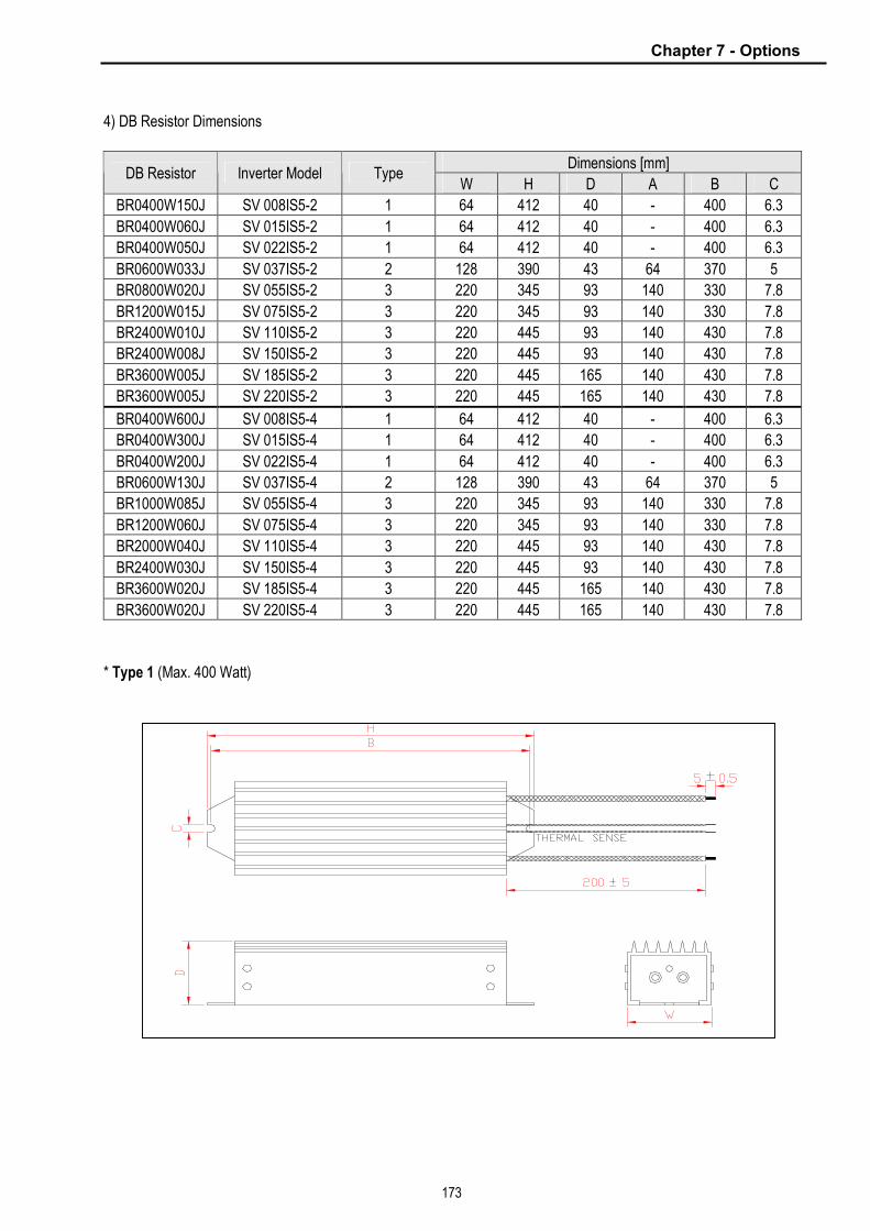
Chapter 7 - Options
173
4) DB Resistor Dimensions
Dimensions [mm] DB Resistor Inverter Model Type
W H D A B C
BR0400W150J SV 008IS5-2 1 64 412 40 - 400 6.3
BR0400W060J SV 015IS5-2 1 64 412 40 - 400 6.3
BR0400W050J SV 022IS5-2 1 64 412 40 - 400 6.3
BR0600W033J SV 037IS5-2 2 128 390 43 64 370 5
BR0800W020J SV 055IS5-2 3 220 345 93 140 330 7.8
BR1200W015J SV 075IS5-2 3 220 345 93 140 330 7.8
BR2400W010J SV 110IS5-2 3 220 445 93 140 430 7.8
BR2400W008J SV 150IS5-2 3 220 445 93 140 430 7.8
BR3600W005J SV 185IS5-2 3 220 445 165 140 430 7.8
BR3600W005J SV 220IS5-2 3 220 445 165 140 430 7.8
BR0400W600J SV 008IS5-4 1 64 412 40 - 400 6.3
BR0400W300J SV 015IS5-4 1 64 412 40 - 400 6.3
BR0400W200J SV 022IS5-4 1 64 412 40 - 400 6.3
BR0600W130J SV 037IS5-4 2 128 390 43 64 370 5
BR1000W085J SV 055IS5-4 3 220 345 93 140 330 7.8
BR1200W060J SV 075IS5-4 3 220 345 93 140 330 7.8
BR2000W040J SV 110IS5-4 3 220 445 93 140 430 7.8
BR2400W030J SV 150IS5-4 3 220 445 93 140 430 7.8
BR3600W020J SV 185IS5-4 3 220 445 165 140 430 7.8
BR3600W020J SV 220IS5-4 3 220 445 165 140 430 7.8
* Type 1 (Max. 400 Watt)

Chapter 7 - Options
174
* Type 2 (Max. 600 Watt)
* Type 3
A

Chapter 7 - Options
175
7.7 DB (Dynamic Brake) Unit
1) DBU models
UL Inverter Applicable motor rating DB Unit Dimension
200V 11 ~ 15 kW SV150DBU-2
200V 18.5 ~ 22 kW SV220DBU-2
Group 1.
See 4) Dimensions
200V 30 ~ 37 kW SV370DBU-2
200V 45 ~ 55 kW SV550DBU-2
Group 2.
See 4) Dimensions
400V 11 ~ 15 kW SV150DBU-4
400V 18.5 ~ 22 kW SV220DBU-4
Group 1.
See 4) Dimensions
400V 30 ~ 37 kW SV370DBU-4
400V 45 ~ 55 kW SV550DBU-4
Non UL
type
400V 75 kW SV750DBU-4
Group 2.
See 4) Dimensions
200V 11 ~ 15 kW SV150DBU-2U
200V 18.5 ~ 22 kW SV220DBU-2 U
200V 30 ~ 37 kW SV370DBU-2 U
200V 45 ~ 55 kW SV550DBU-2 U
400V 11 ~ 15 kW SV150DBU-4 U
400V 18.5 ~ 22 kW SV220DBU-4 U
400V 30 ~ 37 kW SV370DBU-4 U
400V 45 ~ 55 kW SV550DBU-4 U
UL Type
400V 75 kW SV750DBU-4 U
Group 3.
See 4) Dimensions
2) Terminal configuration
- Group 1:
- Group 2:
- Group 3:
Terminal Description
G Grounding terminal
B2 Connect it to DB Resistor terminal B2
B1 Connect it to DB Resistor terminal B1
N Connect it to Inverter terminal N
P Connect it to Inverter terminal P
CM Common for Terminal OH
OH* Overheat Trip Output Terminal
(Open Collector output: 20mA, 27V DC)
B2 B1 N P CM OH G
N B2 P/B1 G
B2 B1 N P G
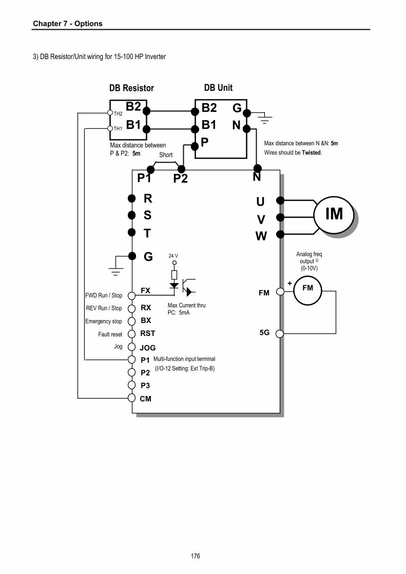
Chapter 7 - Options
176
3) DB Resistor/Unit wiring for 15-100 HP Inverter
IM U
V
W
G
R
S
T
P2
DB Resistor
FX
RX
BX
RST
JOG
P2
P3
FM +
FM
5G
Analog freq output 2) (0-10V)
P1
REV Run / Stop
FWD Run / Stop
Fault reset
Jog
Max Current thru PC: 5mA
CM
24 V
TH1
TH2
Max distance between N &N: 5m
Wires should be Twisted.
Multi-function input terminal
(I/O-12 Setting: Ext Trip-B)
P1
Short
N
N B1
G B2 B2
B1
DB Unit
Max distance between P & P2: 5m
P
Emergency stop
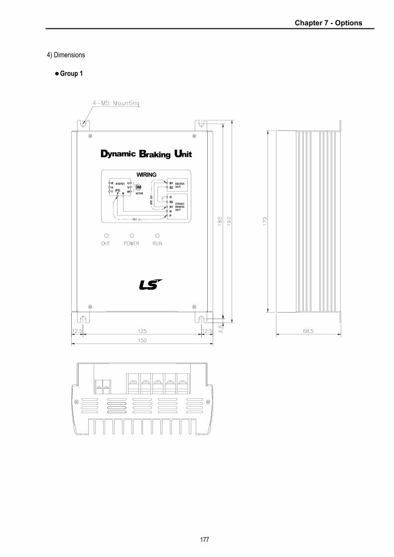
Chapter 7 - Options
177
4) Dimensions
l Group 1
(Unit: mm)
N
ynamic
TP
D
R
S(P2) W
N
P
B2
B1
G
rakingB
WIRING
V
U
IM
nitU
B2
B1

Chapter 7 - Options
178
l Group 2
5.5
258
5
245
2-Ø5.5
80
80
123
Dynamic Braking Unit
RESET
POWER
RUN
OHT
OCT
231.
5
12
15
27
130
75
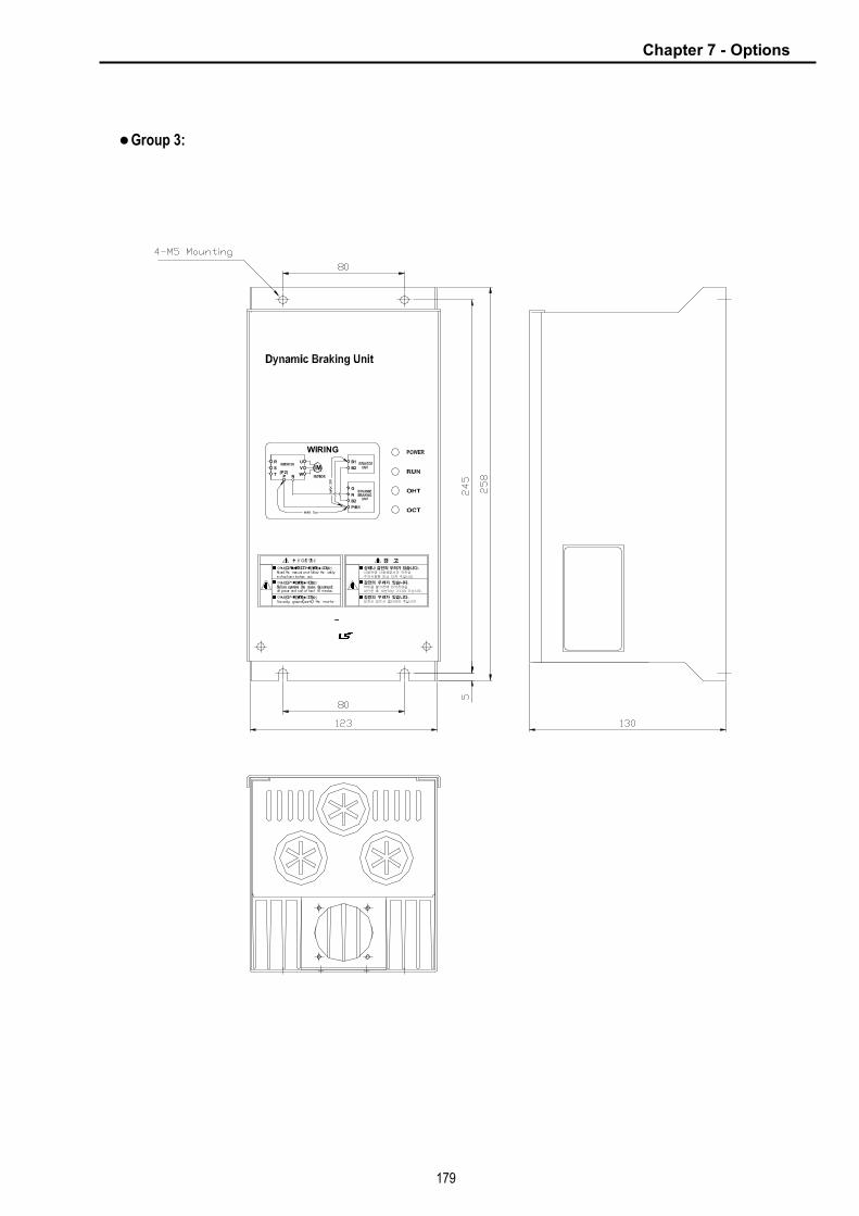
Chapter 7 - Options
179
l Group 3:
P/B1
B2
N
G
B2
B1R
S
T
IMW
V
U
N
WIRING
P(P2)
Risk of Electric Shock
Risk of Electric Shock
Risk of Injury or Electric Shock
W ARNING
설치시 반드시 접 하여 주십시 .
상해나 감 의 우려가 있습니다.
주 사항 고 주십시 .
차단한 후 10분 상 기다려 주십시 .
감 의 우려가 있습니다.
감 의 우려가 있습니다.
커버를 열기전에 력전원
사 전에 사 설명서 안전상
경 고

Chapter 7 - Options
180
(5) Monitoring LEDs
* Group 1
* Group 2
* Group 3
RESET
POWER
RUN
OHT
OCT
POWER
RUN
OHT
OCT
FOT
LED Description OHT
(GREEN, LEFT)
When heat sink is overheated and the level exceeds its setting limit, overheat protection is activated and OHT LED is turned ON after DBU’s signal is shut off.
POWER (RED)
POWER LED is turned ON upon inverter Power ON because normally it is connected to the inverter.
RUN (GREEN, RIGHT)
RUN LED is blinking while DBU is operating normally by motor regenerating energy.
OHT POWER RUN
LED Description
RESET Press this switch to release OCT FAULT status. Pressing this turns the OCT LED off.
POWER (GREEN)
POWER LED is turned ON upon inverter Power ON because normally it is connected to the inverter.
RUN (GREEN)
RUN LED is blinking while DBU is operating normally by motor regenerating energy.
OHT (RED) When heat sink is overheated and the level exceeds its setting
limit, overheat protection is activated and OHT LED is turned ON
after DBU’s signal is shut off.
OCT (RED) Over current trip signal. When overcurrent is flowed to the iGBT, protection function shuts off the operating signal and OCT LED is tured ON.
LED Description POWER (RED)
POWER LED is turned ON upon inverter Power ON because normally it is connected to the inverter.
RUN (GREEN)
RUN LED is blinking while DBU is operating normally by motor regenerating energy.
OHT (RED)
When heat sink is overheated and the level exceeds its setting limit, overheat protection is activated and OHT LED is turned ON after DBU’s signal is shut off.
OCT (RED)
Over current trip signal. When overcurrent is flowed to the iGBT, protection function shuts off the operating signal and OCT LED is tured ON.
FOT (RED)
FOT LED is turned ON when fuse is opened to shut the overcurrent during braking.
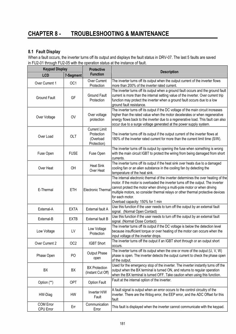
181
CHAPTER 8 - TROUBLESHOOTING & MAINTENANCE
8.1 Fault Display When a fault occurs, the inverter turns off its output and displays the fault status in DRV-07. The last 5 faults are saved
in FU2-01 through FU2-05 with the operation status at the instance of fault.
Keypad Display
LCD 7-Segment
Protective Function
Description
Over Current 1 OC1 Over Current
Protection The inverter turns off its output when the output current of the inverter flows more than 200% of the inverter rated current.
Ground Fault GF Ground Fault
Protection
The inverter turns off its output when a ground fault occurs and the ground fault current is more than the internal setting value of the inverter. Over current trip function may protect the inverter when a ground fault occurs due to a low ground fault resistance.
Over Voltage OV Over voltage
protection
The inverter turns off its output if the DC voltage of the main circuit increases higher than the rated value when the motor decelerates or when regenerative energy flows back to the inverter due to a regenerative load. This fault can also occur due to a surge voltage generated at the power supply system.
Over Load OLT
Current Limit Protection (Overload Protection)
The inverter turns off its output if the output current of the inverter flows at 180% of the inverter rated current for more than the current limit time (S/W).
Fuse Open FUSE Fuse Open The inverter turns off its output by opening the fuse when something is wrong with the main circuit IGBT to protect the wiring from being damaged from short currents.
Over Heat OH Heat Sink Over Heat
The inverter turns off its output if the heat sink over heats due to a damaged cooling fan or an alien substance in the cooling fan by detecting the temperature of the heat sink.
E-Thermal ETH Electronic Thermal
The internal electronic thermal of the inverter determines the over heating of the motor. If the motor is overloaded the inverter turns off the output. The inverter cannot protect the motor when driving a multi-pole motor or when driving multiple motors, so consider thermal relays or other thermal protective devices for each motor. Overload capacity: 150% for 1 min
External-A EXTA External fault A Use this function if the user needs to turn off the output by an external fault signal. (Normal Open Contact)
External-B EXTB External fault B Use this function if the user needs to turn off the output by an external fault signal. (Normal Close Contact)
Low Voltage LV Low Voltage Protection
The inverter turns off its output if the DC voltage is below the detection level because insufficient torque or over heating of the motor can occurs when the input voltage of the inverter drops.
Over Current 2 OC2 IGBT Short The inverter turns off the output if an IGBT short through or an output short occurs.
Phase Open PO Output Phase
open
The inverter turns off its output when the one or more of the output (U, V, W) phase is open. The inverter detects the output current to check the phase open of the output.
BX BX BX Protection
(Instant Cut Off)
Used for the emergency stop of the inverter. The inverter instantly turns off the output when the BX terminal is turned ON, and returns to regular operation when the BX terminal is turned OFF. Take caution when using this function.
Option (**) OPT Option Fault Fault at the internal option of the inverter.
HW-Diag HW Inverter H/W
Fault
A fault signal is output when an error occurs to the control circuitry of the inverter. There are the Wdog error, the EEP error, and the ADC Offset for this fault
COM Error CPU Error
Err Communication
Error This fault is displayed when the inverter cannot communicate with the keypad.

Chapter 8 - Troubleshooting & Maintenance
182
Keypad Display
LCD 7-Segment
Protective Function
Description
LOP LOR LOV LOI LOX
PL RL VL IL XL
Operating Method when the
Frequency Reference is Lost
According to the I/O-48 [Operating Method when the Frequency Reference is Lost] setting, there are three modes: continue operation, decelerate and stop, and free run, LOP: Displayed when option frequency reference is lost (DPRAM time out) LOR: Displayed when option frequency reference is lost (Communication network fault) LOV: Displayed when ‘V1’ analog frequency reference is lost. LOI: Displayed when ‘I‘ analog frequency reference is lost. LOX: Displayed when sun-board (V2, ENC) analog frequency reference is lost.
Inv. OLT IOLT Inverter Overload The inverter turns off its output when the output current of the inverter flows more than the rated level (150% for 1 minute, 200% for 0.5 seconds).
NTC open NTC Thermal Sensor
Opened
Inverter uses NC thermal sensor for detecting heat sink temperature. If this message is displayed, the thermal sensor wire may be cut. (Inverter keeps operating)
Over Speed OSPD Overspeed Inverter shuts off its output when a motor rotates at the frequency exceeding 20 Hz of its max speed.
MC Fail MCF M/C Fail It is displayed when input power is not applied or M/C inside the inverter malfunctions.
To reset fault, Press RESET key, Close RST-CM terminals or connect input power.
If a problem persists, please contact the factory or your local distributor.

Chapter 8 - Troubleshooting & Maintenance
183
8.2 Fault Remedy
Protective Function
Cause Remedy
Over Current Protection
1) Acceleration/Deceleration time is too short compared to the GD²of the load.
2) Load is larger than the inverter rating. 3) Inverter turns output on when the motor is free running. 4) Output short or ground fault has occurred. 5) Mechanical brake of the motor is operating too fast. 6) Components of the main circuit have overheated due
to a faulty cooling fan.
1) Increase Accel/Decel time. 2) Increase inverter capacity. 3) Operate after motor has stopped. 4) Check output wiring. 5) Check mechanical brake operation. 6) Check cooling fan. (Caution) Operating inverter prior to correcting fault may damage the IGBT.
Ground Current Protection
1) Ground fault has occurred at the output wiring of inverter. 2) The insulation of the motor is damaged due to heat.
1) Investigate the output wiring of inverter. 2) Exchange motor.
Over Voltage Protection
1) Acceleration time is too short compared to the GD²of
load. 2) Regenerative load at the output 3) Line voltage high
1) Increase deceleration time. 2) Use regenerative resistor option. 3) Check line voltage.
Current Limit Protection (Overload Protection)
1) Load is larger than the inverter rating. 2) Incorrect inverter capacity selected. 3) Set incorrect V/F pattern.
1) Increase capacity of motor and inverter. 2) Select correct inverter capacity. 3) Select correct V/F pattern.
Fuse Damage 1) Damaged due to over use of over current protection. 2) Damaged due to instant deceleration when motor is at an
excessive excitation status.
Exchange the fuse. (Caution) The IGBT receives damages on many occasions when Fuse Open Trip occurs.
Heat Sink Overheat
1) Cooling fan damaged or an alien substance inserted. 2) Cooling system has faults. 3) Ambient temperature high.
1) Exchange cooling fans and/or eliminate alien substance.
2) Check for alien substances in the heat sink. 3) Keep ambient temperature under 40 ℃.
Electronic Thermal
1) Motor has overheated. 2) Load is larger than inverter rating. 3) ETH level too low. 4) Incorrect inverter capacity selected. 5) Set incorrect V/F pattern. 6) Operated too long at low speeds.
1) Reduce load and/or running duty. 2) Increase inverter capacity. 3) Adjust ETH level to an appropriate level. 4) Select correct inverter capacity. 5) Select correct V/F pattern. 6) Install a cooling fan with a separate power supply.
External fault A External fault has occurred. Eliminate fault at circuit connected to external fault terminal or cause of external fault input.
External fault B External fault has occurred. Eliminate fault at circuit connected to external fault terminal or cause of external fault input.
Low Voltage Protection
1) Line voltage low. 2) Load larger than line capacity is connected to line.
(welding machine, motor with high starting current connected to the commercial line)
3) Faulty magnetic switch at the input side of the inverter
1) Check line voltage. 2) Increase line capacity. 3) Exchange magnetic switch.
Over Current 2
1) Short has occurred between the upper and lower IGBT. 2) Short has occurred at the output of the inverter. 3) Acceleration/Deceleration time is too short compared to
the GD²of load.
1) Check IGBT. 2) Check output wiring of inverter. 3) Increase acceleration time.
Output Phase Open
1) Faulty contact of magnetic switch at output 2) Faulty output wiring
1) Check magnetic switch at output of inverter. 2) Check output wiring.
Overspeed 1) Encoder wiring error (A and B wiring switched) 2) Encoder parameter setting is incorrect. 3) Sub-B board or Encoder error
1) Check for the wiring of inverter and encoder 2) Check for parameter setting of EXT-14, 15, and 16. 3) Exchange inverter and encoder for a new one.
H/W Fault 1) Wdog error (CPU fault) 2) EEP error (memory fault)
Exchange inverter.

Chapter 8 - Troubleshooting & Maintenance
184
Protective Function
Cause Remedy
3) ADC Offset (current feedback circuit fault)
Communication Fault
1) Faulty connection between inverter and keypad 2) Inverter CPU malfunction
1) Check connector. 2) Exchange inverter.
Operating Method when the
Speed Reference is
Lost
LOP (Loss of reference from the Option), LOR (Remote) LOV (V1), LOI (I), LOX (Sub-V2, ENC)
Eliminate cause of fault.
Inverter Overload
1) Load is larger than inverter rating. 2) Incorrect inverter capacity selected.
1) Increase motor and/or inverter capacity. 2) Select correct inverter capacity.
M/C Fail M/C does not work properly. Check the operating contact is closed after giving
signal.

Chapter 8 - Troubleshooting & Maintenance
185
8.3 Troubleshooting
Condition Check Point
The Motor Does Not Rotate.
1) Main circuit inspection:
☞ Is the input (line) voltage normal? (Is the LED in the inverter is lit?)
☞ Is the motor connected correctly? 2) Input signal inspection:
☞ Check the operating signal input to the inverter.
☞ Check the forward and the reverse signal input simultaneously to the inverter?
☞ Check the command frequency signal input to the inverter. 3) Parameter setting inspection:
☞ Is the reverse prevention (FU1-03) function set?
☞ Is the operation mode (FU1-01) set correctly?
☞ Is the command frequency set to 0? 4) Load inspection:
☞ Is the load too large or is the motor jammed? (Mechanical brake) 5) Other:
☞ Is the alarm displayed on the keypad or is the alarm LED lit? (STOP LED blinks)
The Motor Rotates in Opposite Directions.
☞ Is the phase sequence of the output terminal U, V, W correct?
☞ Is the starting signal (forward/reverse) connected correctly?
The Difference Between the Rotating Speed and the Reference is Too Large.
☞ Is the frequency reference signal correct? (Check the level of the input signal)
☞ Is the following parameter setting is correct? Lower Limit Frequency (FU1-24), Upper Limit Frequency (FU1-25), Analog Frequency Gain (I/O-1~10)
☞ Is the input signal line influenced by external noise? (Use a shielded wire)
The Inverter Does Not Accelerate or Decelerate Smoothly.
☞ Is the acceleration/deceleration time is set too short a period of time?
☞ Is the load too large?
☞ Is the Torque Boost (FU1-27, 28) value is too high that the current limit function and the stall prevention function do not operate?
The Motor Current is Too High.
☞ Is the load too large?
☞ Is the Torque Boost Value (manual) too high?
The Rotating Speed Does Not Increase.
☞ Is the Upper Limit Frequency (FU1-25) value correct?
☞ Is the load too large?
☞ Is the Torque Boost (FU1-27, 28) value too high that the stall prevention function (FU1-59, 60) does not operate?
The Rotating Speed Oscillates When the Inverter is Operating.
1) Load inspection:
☞ Is the load oscillating? 2) Input signal inspection:
☞ Is the frequency reference signal oscillating? 3) Other:
☞ Is the wiring too long when the inverter is using V/F control? (over 500m)
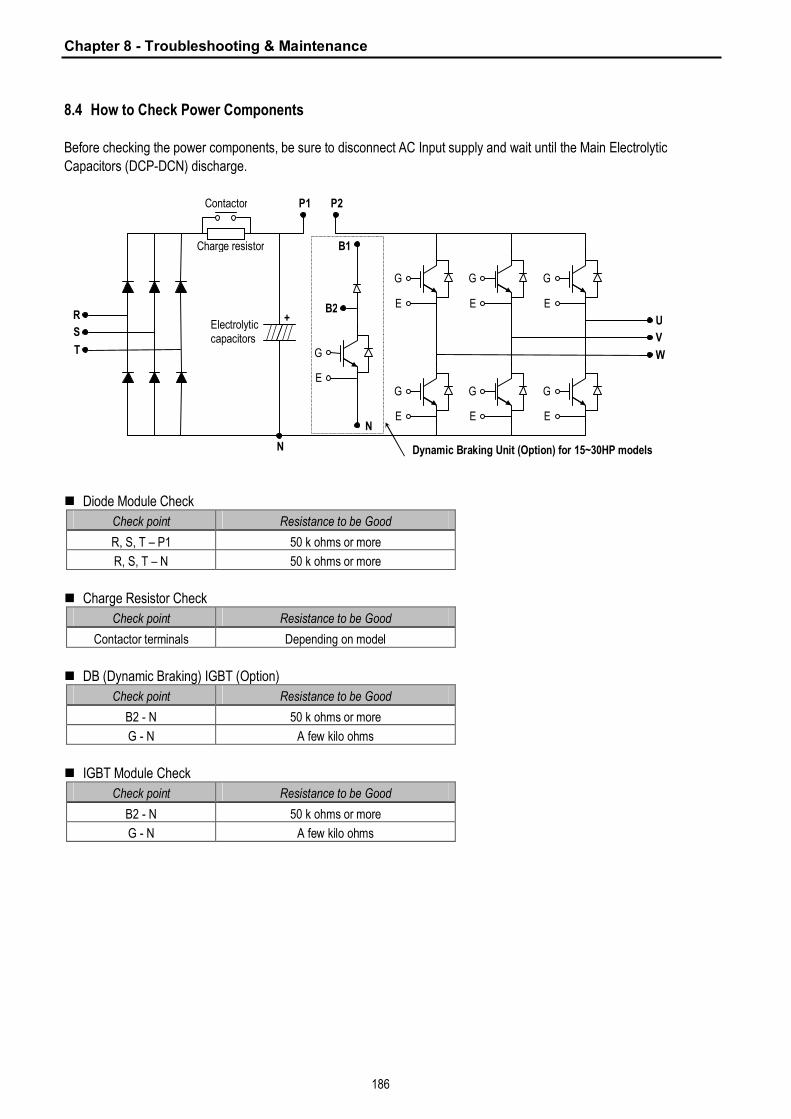
Chapter 8 - Troubleshooting & Maintenance
186
8.4 How to Check Power Components Before checking the power components, be sure to disconnect AC Input supply and wait until the Main Electrolytic
Capacitors (DCP-DCN) discharge.
n Diode Module Check
Check point Resistance to be Good
R, S, T – P1 50 k ohms or more
R, S, T – N 50 k ohms or more
n Charge Resistor Check
Check point Resistance to be Good
Contactor terminals Depending on model
n DB (Dynamic Braking) IGBT (Option)
Check point Resistance to be Good
B2 - N 50 k ohms or more
G - N A few kilo ohms
n IGBT Module Check
Check point Resistance to be Good
B2 - N 50 k ohms or more
G - N A few kilo ohms
R
G
E
G
E
G
E
G
E
G
E
G
E
S
T
U
V
W G
E
P1 P2
B1
N
Dynamic Braking Unit (Option) for 15~30HP models N
Charge resistor
Contactor
+ Electrolytic capacitors
B2

Chapter 8 - Troubleshooting & Maintenance
187
8.5 Maintenance The iS5 series is an industrial electronic product with advanced semiconductor elements. However, temperature,
humidity, vibration and aging parts may still affect it. To avoid this, it is recommended to perform routine inspections.
8.5.1 Precautions
n Be sure to remove the drive power input while performing maintenance.
n Be sure to perform maintenance only after checking that the bus has discharged. The bus capacitors in the
electronic circuit can still be charged even after the power is turned off.
n The correct output voltage can only be measured by using a rectifier voltage meter. Other voltage meters,
including digital voltage meters, are likely to display incorrect values caused by the high frequency PWM output
voltage of the drive.
8.5.2 Routine Inspection
Be sure to check the following before operation:
n The conditions of the installation location
n The conditions of the drive cooling
n Abnormal vibration
n Abnormal heating
8.5.3 Periodical Inspection
n Are there any loose bolt, nut or rust caused by surrounding conditions? If so, tighten them up or replace them.
n Are there any deposits inside the drive-cooling fan? If so, remove using air.
n Are there any deposits on the drive’s PCB (Printed Circuit Boards)? If so, remove using air.
n Are there any abnormalities in the various connectors of the drive’s PCB? If so, check the condition of the connector
in question.
n Check the rotating condition of the cooling fan, the size and condition of the capacitors and the connections with the
magnetic contactor. Replace them if there are any abnormalities.
8.5.4 Internal Fuse Replacement
When the internal fuse is opened the IGBT’s should be checked thoroughly before replacing the fuse.
Contact the factory for replacement fuse information.

Chapter 8 - Troubleshooting & Maintenance
188
8.6 Daily and Periodic Inspection Items
Period
Insp
ecti
on
Lo
cati
on
Insp
ecti
on
Item
Inspection
Dai
ly
1 ye
ar
2 ye
ar
Inspection Method Criterion Measuring Instrument
Ambient Environ-
ment
Is there any dust? Is the ambient temperature and humidity adequate? O
Refer to the precautions. Temperature: -10~+40 no freezing. Humidity: Under 50% no dew
Thermometer, Hygrometer, Recorder
Equipment Is there any abnormal oscillation or noise? O Use sight and hearing. No abnormality
All
Input Voltage
Is the input voltage of the main circuit normal?
O Measure the voltage between the terminals R, S, T.
Digital Multi-Meter/Tester
All
Megger check (between the main circuit and the ground) Are any fixed parts removed? Are there any traces of overheating at each component’s cleaning?
O
O O
O
Undo the inverter connections short the terminals R, S, T, U, V, W and measure between these parts and the ground. Tighten the screws. Visual check.
Over 5MΩ No fault
DC 500V class Megger
Conductor/Wire
Is the conductor rusty? Is the wire coating damaged?
O O
Visual check No fault
Terminal Is there any damage? O Visual check No fault
IGBT Module /Diode Module
Check the resistance between each of the terminals.
O Undo the inverter connection and measure the resistance between R, S, T ⇔ P, N and U, V, W ⇔ P, N with a tester.
(Refer ‘How to Check Power Components”)
Digital Multi-Meter/Analog Tester
Smoothing Capacitor
Is there any liquid coming out? Is the safety pin out, and is there any swelling? Measure the capacitance.
O O
O
Visual check Measure with a capacitance-measuring device.
No fault Over 85% of the rated capacity
Capacitance Measuring Device
Relay Is there any chattering noise during operation? Is there any damage to the contact
O O
Auditory check Visual check
No fault
Mai
n C
ircui
t
Resistor
Is there any damage to the resistor insulation? Is the wiring in the resistor damaged (open)?
O O
Visual check Disconnect one of the connections and measure with a tester.
No fault Error must be within ±10% the displayed resistance.
Digital Multi-Meter/Analog Tester
Con
trol
Circ
uit
Pro
tect
ive
Circ
uit
Operation Check
Is there any unbalance between each phases of the output voltage? Nothing must be wrong with display circuit after executing the sequence protective operation.
O
O
Measure the voltage between the output terminals U, V and W. Short and open the inverter protective circuit output.
The voltage balance between the phases for 200V (800V) class is under 4V (8V). The fault circuit operates according to the sequence.
Digital Multi-Meter/Rectifying Voltmeter
Coo
ling
Sys
tem
Cooling Fan
Is there any abnormal oscillation or noise? Is the connection area loose?
O O
Turn OFF the power and turn the fan by hand. Tighten the connections.
Must rotate smoothly. No fault
Dis
play
Meter
Is the displayed value correct? O O Check the meter reading at the exterior of the panel.
Check the specified and management values.
Voltmeter/ Ammeter etc.
All Are there any abnormal vibrations or noise? Is there any unusual odor?
O O
Auditory, sensory, visual check. Check for overheat and damage.
No fault
Mot
or
Insulation Resistor
Megger check (between the output terminals and the ground terminal)
O Undo the U, V and W connections and tie the motor wiring.
Over 5MΩ 500V class Megger
☞ Note: Values in ( ) is for the 400V class inverters.

189
APPENDIX A - FUNCTIONS BASED ON USE
Set the function properly according to the load and operating conditions. Application and related functions are listed in
the following table.
Use Related Parameter Code
Accel/Decel Time, Pattern Adjustment DRV-01 [Acceleration Time], DRV-02 [Deceleration Time], FU1-05 [Acceleration Pattern], FU1-06 [Deceleration Pattern]
Reverse Rotation Prevention FU1-03 [Forward, Reverse Prevention]
Minimum Accel/Decel Time FU1-05 [Acceleration Pattern], FU1-06 [Deceleration Pattern] Accel/Decel at Continuous Rating Range FU1-05 [Acceleration Pattern], FU1-06 [Deceleration Pattern]
Braking Operation Adjustment FU1-07 [Stop Method], FU1-08~11 [DC Braking], FU1-12~13 [DC braking at start]
Operations for Frequencies Over 60 Hz
FU1-20 [Maximum Frequency], FU1-25 [Frequency Upper Limit], I/O-05 [Frequency Corresponding to Max. Voltage of V1], I/O-10 [Frequency Corresponding to Max. Current of I]
Selecting an Appropriate Output Characteristics for the Load
FU1-20 [Maximum Frequency], FU1-21 [Base Frequency]
Motor Output Torque Adjustment
FU1-22 [Starting Frequency], FU1-26~28 [Torque Boost], FU1-59~60 [Stall Prevention], FU2-30 [Rated Motor]
Output Frequency Limit FU1-23~25 [Frequency Upper/Lower Limit], I/O-01~10 [Analog Frequency Setting]
Motor Overheat Protection FU1-50~53 [Electronic Thermal], FU2-30 [Rated Motor]
Multi Step Operation I/O-12~14 [Define the Multi Function Input Terminals], I/O-20~27 [Jog, Multi Step Frequency], FU1-23~25 [Frequency Upper/Lower Limit]
Jog Operation I/O-20 [Jog Frequency] Frequency Jump Operation FU2-10~16 [Frequency Jump]
Timing the Electronic Brake Operation I/O-42~43 [Frequency Detection Level], I/O-44 [Multi Function Output]
Displaying the Rotating Speed DRV-04 [Motor Speed], FU2-74 [Motor RPM Display Gain]
Function Alteration Prevention FU2-94 [Parameter Lock] Energy Saving FU1-39 [Energy Saving] Auto Restart Operation After Alarm Stop FU2-27~28 [Auto Retry] 2nd Motor Operation FU2-81~90 [2nd Function] PID Feedback Operation FU2-50~54 [PID Operation] Frequency Reference Signal and Output Adjusting
I/O-01~10 [Analog Frequency Setting]
Define the Multi-Function Input Terminals I/O-12~14 [Define the Multi-Function Input Terminals] Define the Multi-Function Input Terminals I/O-44 [Multi Function Auxiliary Contact Output Setting]
Commercial Line ⇔ inverter Switchover
Operation
I/O-12~14 [Define the Multi-Function Input Terminals], I/O-44 [Multi-Function Auxiliary Contact Output Setting]
Frequency Meter Calibration I/O-40~41 [FM Output]
Operate by Communicating with a Computer I/O-46 [Inverter No.], I/O-47 [communication Speed], I/O-48~49 [Loss of Reference]

190
APPENDIX B - PARAMETERS BASED ON APPLICATION
Application Parameter Code
DRV Group
When you want to change the frequency setting DRV-00
When you want to change the acceleration and deceleration time of the motor DRV-01, DRV-02
When you want to change the run/stop method DRV-03
When you want to change the frequency reference source DRV-04
When you want to set the multi-function DRV-005 ~ 07
When you want to see the output current, motor speed and the DC link voltage of inverter DRV-08 ~ 10
When you want to see the output voltage, output power, output torque from the user display DRV-11
When you want to check the fault of the inverter DRV-12
FU1 Group
When you want to use the Jump Code FU1-00
When you want to prevent the motor from rotating at opposite directions FU1-03
When you want to select the acceleration and deceleration pattern suitable for your application FU1-05 ~ 06
When you want to change the stopping method FU1-07
When you want to change the stopping accuracy for steady stop FU1-08 ~ 11
When DC injection braking is required before starting FU1-12 ~ 13
When you want to set the maximum frequency and the base frequency according to the rated torque of the
motor
FU1-20 ~ 21
When you want to adjust the starting frequency FU1-22
When you want to limit the mechanical rotating speed to a fixed value FU1-23 ~ 25
When a large starting torque is needed for loads such as elevators (Manual/Auto Torque Boost) FU1-26 ~ 28
When you want to select an appropriate output characteristic (V/F characteristic) according to loads FU1-29
When you want to se up your own V/F pattern FU1-30 ~ 37
When you want to adjust the output voltage of the inverter FU1-38
When you want to use the energy saving function FU1-39
When you want to protect the motor from overheating FU1-50 ~ 53
When you want to output a signal when the overload condition lasts more than a fixed amount of time FU1-54 ~ 55
When you want to cut off the output when the overload condition lasts more than a fixed amount of time FU1-56 ~ 58
When you want to set the stall prevention function FU1-59 ~ 60
FU2 Group
When you want to check the fault history of the inverter FU2-01 ~ 06
When you want to use dwell function FU2-07 ~ 08
When you want to prevent the resonance from the oscillating characteristics of a machine FU2-10 ~ 16
When you want to protect inverter from input/output phase loss FU2-19
When you want to start the inverter as soon as the power is turned ON FU2-20
When you want to restart the inverter by resetting the fault when a fault occur FU2-21
When you want to use the instant power failure restart function (Speed Search) FU2-22 ~ 25
When you want to use the retry function FU2-26 ~ 27
When you want to enter the motor constants FU2-30 ~ 37
When you want to reduce noise or leakage current by changing the PWM carrier frequency FU2-39 When you want to change the control method (V/F, slip compensation, PID, or sensorless operation) FU2-40
When you want to use the auto tuning function FU2-41 ~ 44
When you want to operate using PID feedback FU2-50 ~ 54
When you want to change the reference frequency for acceleration and deceleration FU2-70

191
Application Parameter Code When you want to change the acceleration and deceleration time scale FU2-71
When you want to set the initial keypad display that is displayed when the power is turned ON FU2-72 When you want to set the user defined display FU2-73
When you want to adjust the gain for the motor RPM display FU2-74 When you want to set the dynamic braking (DB) resistor mode FU2-75 ~ 76
When you want to verify the inverter software version FU2-79
When you want to change the connection from one motor to the other motor which use difference parameters FU2-81 ~ 90 When you want to copy the inverter parameter to another inverter FU2-91 ~ 92
When you want to initialize the parameters FU2-93
When you want to prevent the parameters from being changed FU2-94
I/O Group When you want to set the analog voltage or current for the frequency reference I/O-01 ~ 10
When you want to set the operating method when the frequency reference is lost I/O-11
When you want to change the functions for the input terminals P1, P2, and P3 I/O-12 ~ 14 When you want to check the status of the input/output terminals I/O-15 ~ 16
When you want to change the response time of the input terminals I/O-17
When you want to use the JOG and multi step speed operation I/O-20 ~ 24 When you want to change the 1st ~ 7th acceleration/deceleration time I/O-25 ~ 38
When you want to use the FM meter terminal output I/O-40 ~ 41 When you want to set the frequency detection level I/O-42 ~ 43
When you want to change the functions of the multi function auxiliary contact output (AXA-AXC) I/O-44
When you want to exchange the motor to commercial power line from inverter or the opposite I/O-44
When you want to use the fault relay (30A, 30B, 30C) functions I/O-45
When you want to use RS232/485 communication I/O-46 ~ 47 When you want to set the operating method when the frequency reference is lost I/O-48 ~ 49
When you want to use the auto (sequence) operation I/O-50 ~ 84
EXT Group (When a Sub-board and/or an option board is installed)
When you want to define the functions for the input terminals P4, P5, P6 (SUB-A, SUB-C) EXT-02 ~ 04 When you want to use the analog voltage (V2) input (SUB-A, SUB-C) EXT-05 ~ 10 When you want to use the encoder pulse for feedback to control the motor speed, or use the pulse input for frequency reference (SUB-B)
EXT-14 ~ 24
When you want to change the functions of the output terminals Q1, Q2, Q3 (SUB-A, SUB-C) EXT-30 ~ 32
When you want to use the LM meter terminal output (SUB-A, SUB-C) EXT-34 ~ 35
When you want to use the analog outputs (AM1, AM2 terminals) EXT-40 ~ 43

192
APPENDIX C- PERIPHERAL DEVICES
Wire, mm2 (AWG) Inverter Models
Motor [HP]
MCCB, ELB Magnetic Contactor R, S, T U, V, W Ground
AC Input Fuse
AC Reactor DC Reactor
SV008iS5-2 1 TD125U/EBS33b GMC-9 2 (14) 2 (14) 3.5 (12) 10 A 2.13 mH, 5.7 A 7.00 mH, 5.4 A SV015iS5-2 2 TD125U/EBS33b GMC-12 2 (14) 2 (14) 3.5 (12) 15 A 1.20 mH, 10 A 4.05 mH, 9.2 A SV022iS5-2 3 TD125U/EBS33b GMC-18 2 (14) 2 (14) 3.5 (12) 25 A 0.88 mH, 14 A 2.92 mH, 13 A SV037iS5-2 5 TD125U/EBS33b GMC-32 3.5 (12) 3.5 (12) 3.5 (12) 40 A 0.56 mH, 20 A 1.98 mH, 19 A SV055iS5-2 7.5 TD125U/EBS53b GMC-40 5.5 (10) 5.5 (10) 5.5 (10) 40 A 0.39 mH, 30 A 1.37 mH, 29 A SV075iS5-2 10 TD125U/EBS63b GMC-50 8 (8) 8 (8) 5.5 (10) 50 A 0.28 mH, 40 A 1.05 mH, 38 A SV110iS5-2 15 TD125U/EBS103b GMC-65 14 (6) 14 (6) 14 (6) 70 A 0.20 mH, 59 A 0.74 mH, 56 A SV150iS5-2 20 TD125U/EBS203b GMC-100 22 (4) 22 (4) 14 (6) 100 A 0.15 mH, 75 A 0.57 mH, 71 A SV185iS5-2 25 TS250U/EBS203b GMC-125 30 (3) 30 (3) 22 (4) 100 A 0.12 mH, 96 A 0.49 mH, 91 A SV220iS5-2 30 TS250U/EBS203b GMC-150 38(2) 30 (3) 22 (4) 125 A 0.10 mH, 112 A 0.42 mH, 107 A SV300iS5-2 40 TS250U/EBS203b GMC-180 60(2/0) 60(2/0) 22 (4) 190 A 0.07 mH, 160 A 0.34 mH, 152 A SV370iS5-2 50 TS400U/EBS403b GMC-220 60(2/0) 60(2/0) 22 (4) 220 A 0.06 mH, 191 A 0.29 mH, 181 A SV450iS5-2 60 TS400U/EBS403b GMC-300 100(4/0) 100(4/0) 38 (2) 270 A 0.05 mH, 223 A 0.29 mH, 233 A SV550iS5-2 75 TS800U/EBS603b GMC-400 100(4/0) 100(4/0) 38 (2) 330 A 0.04 mH, 285 A 0.25 mH, 270 A SV008iS5-4 1 TD125U/EBS33b GMC-9 2 (14) 2 (14) 2 (14) 6 A 8.63 mH, 2.8 A 28.62 mH, 2.7 A SV015iS5-4 2 TD125U/EBS33b GMC-9 2 (14) 2 (14) 2 (14) 10 A 4.81 mH, 4.8 A 16.14 mH, 4.6 A SV022iS5-4 3 TD125U/EBS33b GMC-12 2 (14) 2 (14) 2 (14) 10 A 3.23 mH, 7.5 A 11.66 mH, 7.1 A SV037iS5-4 5 TD125U/EBS33b GMC-18 2 (14) 2 (14) 2 (14) 20 A 2.34 mH, 10 A 7.83 mH, 10 A SV055iS5-4 7.5 TD125U/EBS33b GMC-22 3.5 (12) 2 (14) 3.5 (12) 20 A 1.22 mH, 15 A 5.34 mH, 14 A SV075iS5-4 10 TD125U/EBS33b GMC-32 3.5 (12) 3.5 (12) 3.5 (12) 30 A 1.14 mH, 20 A 4.04 mH, 19 A SV110iS5-4 15 TD125U/EBS53b GMC-40 5.5 (10) 5.5 (10) 8 (8) 35 A 0.81 mH, 30 A 2.76 mH, 29 A SV150iS5-4 20 TD125U/EBS63b GMC-50 14 (6) 8 (8) 8 (8) 45 A 0.61 mH, 38 A 2.18 mH, 36 A SV185iS5-4 25 TD125U/EBS103b GMC-65 14 (6) 8 (8) 14 (6) 60 A 0.45 mH, 50 A 1.79 mH, 48 A SV220iS5-4 30 TD125U/EBS103b GMC-65 22 (4) 14 (6) 14 (6) 70 A 0.39 mH, 58 A 1.54 mH, 55 A SV300iS5-4 40 TD125U/EBS203b GMC-100 22 (4) 22 (4) 14 (6) 90 A 0.287mH, 80A 1.191mH, 76A SV370iS5-4 50 TS250U/EBS203b GMC-125 22 (4) 22 (4) 14 (6) 110 A 0.232mH, 98A 0.975mH, 93A SV450iS5-4 60 TS250U/EBS203b GMC-150 38(2) 38(2) 22 (4) 140 A 0.195mH, 118A 0.886mH, 112A SV550iS5-4 75 TS250U/EBS203b GMC-180 38(2) 38(2) 22 (4) 170 A 0.157mH, 142A 0.753mH, 135A SV750iS5-4 100 TS400U/EBS403b GMC-220 60(2/0) 60(2/0) 22 (4) 230 A 0.122mH, 196A 0.436mH, 187A
Note 1. The capacity of the MCCB should be 1.5 to 2 times the rated output current of the drive. 2. Use an MCCB keep the drive from faulting out instead of using overheat protection (150% for
one minute at the rated output current.)

193
SHORT CIRCUIT FUSE/BREAKER MARKING
Use Class H or K5 UL Listed Input Fuse and UL Listed Breaker Only. See the table below for the
Voltage and Current rating of the fuses and the breakers. External Fuse Breaker Internal Fuse
Input Voltage
Motor [kW]
Inverter Current [A]
Voltage [V]
Current [A]
Voltage [V]
Current [A]
Voltage [V]
Maker Model
Number
0.75 SV008 iS5-2
10 500 30 220 10 600 Hinode
Elec 660CF10
1.5 SV015 iS5-2
15 500 30 220 15 600 Hinode
Elec 660CF15
2.2 SV022 iS5-2
25 500 30 220 20 600 Hinode
Elec 660CF20
3.7 SV037 iS5-2
40 500 30 220 30 600 Hinode
Elec 660CF30
5.5 SV055 iS5-2
40 500 50 220 60 250 Hinode
Elec 250FH-60
7.5 SV075 iS5-2
50 500 60 220 60 250 Hinode
Elec 250FH-60
11 SV110 iS5-2
70 500 100 220 125 250 Hinode
Elec 250GH-125
15 SV150 iS5-2
100 500 100 220 150 250 Hinode
Elec 250GH-150
18.5 SV185 iS5-2
100 500 225 220 175 250 Hinode
Elec 250GH-175
22 SV220 iS5-2
125 500 225 220 225 250 Hinode
Elec 250GH-225
30 SV300 iS5-2
150 500 225 220 250 250 Hinode
Elec 250GH-250SUL
37 SV370 iS5-2
220 500 225 220 250 250 Hinode
Elec 250GH-250SUL
45 SV450 iS5-2
270 500 300 220 350 250 Hinode
Elec 250GH-350SUL
200V CLASS
55 SV550 iS5-2
330 500 350 220 350 250 Hinode
Elec 250GH-350SUL
0.75 SV008 iS5-4
10 500 30 460 10 600 Hinode
Elec 660CF10
1.5 SV015 iS5-4
10 500 30 460 10 600 Hinode
Elec 660CF10
2.2 SV022 iS5-4
15 500 30 460 15 600 Hinode
Elec 660CF15
3.7 SV037 iS5-4
20 500 30 460 15 600 Hinode
Elec 660CF15
5.5 SV055 iS5-4
20 500 30 460 35 600 Hinode
Elec 660GH-35
7.5 SV075 iS5-4
30 500 30 460 35 600 Hinode
Elec 660GH-35
11 SV110 iS5-4
35 500 50 460 63 600 Hinode
Elec 660GH-63
15 SV150 iS5-4
45 500 60 460 80 600 Hinode
Elec 660GH-80
18.5 SV185 iS5-4
60 500 100 460 100 600 Hinode
Elec 660GH-100
22 SV220 iS5-4
70 500 100 460 125 600 Hinode
Elec 660GH-125
30 SV300 iS5-4
100 500 100 460 125 600 Hinode
Elec 600FH-125S
37 SV370 iS5-4
100 500 225 460 150 600 Hinode
Elec 600FH-150S
45 SV450 iS5-4
100 500 225 460 200 600 Hinode
Elec 600FH-200S
55 SV550 iS5-4
150 500 225 460 200 600 Hinode
Elec 600FH-200S
400V CLASS
75 SV750 iS5-4
200 500 225 460 125 600 Hinode
Elec 600FH-125S
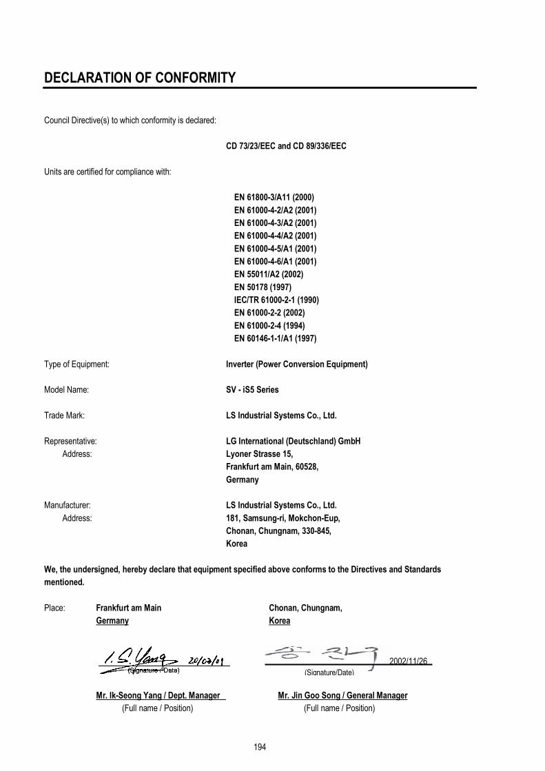
194
DECLARATION OF CONFORMITY
Council Directive(s) to which conformity is declared:
CD 73/23/EEC and CD 89/336/EEC
Units are certified for compliance with:
EN 61800-3/A11 (2000)
EN 61000-4-2/A2 (2001)
EN 61000-4-3/A2 (2001)
EN 61000-4-4/A2 (2001)
EN 61000-4-5/A1 (2001)
EN 61000-4-6/A1 (2001)
EN 55011/A2 (2002)
EN 50178 (1997)
IEC/TR 61000-2-1 (1990)
EN 61000-2-2 (2002)
EN 61000-2-4 (1994)
EN 60146-1-1/A1 (1997)
Type of Equipment: Inverter (Power Conversion Equipment)
Model Name: SV - iS5 Series
Trade Mark: LS Industrial Systems Co., Ltd.
Representative: LG International (Deutschland) GmbH
Address: Lyoner Strasse 15,
Frankfurt am Main, 60528,
Germany
Manufacturer: LS Industrial Systems Co., Ltd.
Address: 181, Samsung-ri, Mokchon-Eup,
Chonan, Chungnam, 330-845,
Korea
We, the undersigned, hereby declare that equipment specified above conforms to the Directives and Standards
mentioned.
Place: Frankfurt am Main Chonan, Chungnam,
Germany Korea
Mr. Ik-Seong Yang / Dept. Manager Mr. Jin Goo Song / General Manager
(Full name / Position) (Full name / Position)
(Signature/Date) 2002/11/26
195
TECHNICAL STANDARDS APPLIED
The standards applied in order to comply with the essential requirements of the Directives 73/23/CEE "Electrical material intended
to be used with certain limits of voltage" and 89/336/CEE "Electromagnetic Compatibility" are the following ones:
• EN 50178 (1997) “Electronic equipment for use in power installations”.
• EN 61800-3/A11 (2000) “Adjustable speed electrical power drive systems. Part 3: EMC product standard
including specific methods”
• EN 55011/A2 (2002) “Industrial, scientific and medical (ISM) radio-frequency equipment. Radio disturbances
characteristics. Limits and methods of measurement”
• EN 61000-4-2/A2 (2001) “Electromagnetic compatibility (EMC). Part 4: Testing and measurement techniques.
Section 2: Electrostatic discharge immunity test.
• EN 61000-4-3/A2 (2001) “Electromagnetic compatibility (EMC). Part 4: Testing and measurement techniques.
Section 3: Radiated, radiofrequency, electromagnetic field immunity test.
• EN 61000-4-4/A2 (2001) “Electromagnetic compatibility (EMC). Part 4: Testing and measurement techniques.
Section 4: Electrical fast transients / burst immunity test.
• EN 61000-4-5/A1 (2000) “Electromagnetic compatibility (EMC). Part 4: Testing and measurement techniques.
Section 5: Surge immunity test.
• EN 61000-4-6/A1 (2001) “Electromagnetic compatibility (EMC). Part 4: Testing and measurement techniques.
Section 6: Immunity to conducted disturbances, induced by radio-frequency fields.
• CEI/TR 61000-2-1 (1990) “Electromagnetic compatibility (EMC). Part 2: Environment. Environment description for
low-frequency conducted disturbances and signalling in public low voltages supply
systems”
• EN 61000-2-2 (2002)
(<22Kw)
“Electromagnetic compatibility (EMC). Part 2: Environment. Compatibility level for low-
frequency conducted disturbances and signalling in public low voltages supply
systems”
• EN 61000-2-4 (1997)
(>22Kw)
“Electromagnetic compatibility (EMC). Part 2: Environment. Compatibility level in
industrial plants for low-frequency conducted disturbances”
• EN 60146-1-1/A1 (1997)
(>22Kw)
“Semiconductor converters. General requirements and line commutated converters. Part
1-1: Specifications of basic requirements”

EMI / RFI POWER LINE FILTERS
196
RFI FILTERS
THE L.G. RANGE OF POWER LINE FILTERS FF (Footprint) – FE (Standard) SERIES, HAVE BEEN SPECIFICALLY DESIGNED WITH HIGH
FREQUENCY LS INVERTERS, THE USE L.G. FILTERS, WITH THE INSTALLATION ADVICE OVERLEAF HELP TO ENSURE TROUBLE
FREE USE ALONG SIDE SENSITIVE DEVICES AND COMPLIANCE TO CONDUCTED EMISSION AND IMMUNITY STANDARDS TO
EN50081 -> EN 61000-6-3:02 and EN 61000-6-1:02
CAUTION
IN CASE OF A LEAKAGE CURRENT PROTECTIVE DEVICES IS USED ON POWER SUPPLY, IT MAY BE FAULT AT POWER-ON OR OFF.
IN AVOID THIS CASE, THE SENSE CURRENT OF PROTECTIVE DEVICE SHOULD BE LARGER THAN VALUE OF LAKAGE CURRENT AT
WORST CASE IN THE BELOW TABLE.
RECOMMENDED INSTALLATION INSTRUCTIONS
To conform to the EMC directive, it is necessary that these instructions be followed as closely as possible. Follow the usual safety
procedures when working with electrical equipment. All electrical connections to the filter, inverter and motor must be made by a
qualified electrical technician.
1-) Check the filter rating label to ensure that the current, voltage rating and part number are correct.
2-) For best results the filter should be fitted as closely as possible to the incoming mains supply of the wiring enclosure, usually directly after the
enclosures circuit breaker or supply switch.
3-) The back panel of the wiring cabinet of board should be prepared for the mounting dimensions of the filter. Care should be taken to remove
any paint etc... from the mounting holes and face area of the panel to ensure the best possible earthing of the filter.
4-) Mount the filter securely.
5-) Connect the mains supply to the filter terminals marked LINE, connect any earth cables to the earth stud provided. Connect the filter
terminals marked LOAD to the mains input of the inverter using short lengths of appropriate gauge cable.
6-) Connect the motor and fit the ferrite core (output chokes) as close to the inverter as possible. Armoured or screened cable should be used
with the 3 phase conductors only threaded twice through the center of the ferrite core. The earth conductor should be securely earthed at both
inverter and motor ends. The screen should be connected to the enclosure body via and earthed cable gland.
7-) Connect any control cables as instructed in the inverter instructions manual.
IT IS IMPORTANT THAT ALL LEAD LENGHTS ARE KEPT AS SHORT AS POSSIBLE AND THAT INCOMING MAINS AND
OUTGOING MOTOR CABLES ARE KEPT WELL SEPARATED.

EMI / RFI POWER LINE FILTERS
197
RFI Filters (Footprint - Standard) for iS5 SERIES
(x) (1) Industrial environment EN 50081-0 (A class) -> EN 61000-6-4:02
(2) Domestic and industrial environment EN 50081-1 (B class) -> EN 61000-6-3:02
iS5 series / Filtros Footprint / Footprint Filters
VARIADOR INVERTER
POT. POWER
CODIGO CODE
INTENS. CURRENT
TENSION VOLTAGE
CORRIENTE DE FUGAS LEAKAGE CURRENT
DIMENSIONES DIMENSIONS L W H
MONTAJE MOUNTING Y X
PESO WEIGHT
TORNILLOS DE FIJACION
MOUNT
CHOQUES DE SALIDA
OUTPUT CHOKES
TRIFASICOS THREE PHASE NOM. MAX. SV008iS5-2 0.8kW SV015iS5-2 1.5kW
FFS5-T012-(x) 12A 250VAC 0.3A 18A 329 x 149.5 x 50 315 x 120 M5 FS – 2
SV022iS5-2 2.2kW SV037iS5-2 3.7kW
FFS5-T020-(x) 20A 250VAC 0.3A 18A 329 x 149.5 x 50 315 x 120 M5 FS – 2
SV055iS5-2 5.5kW FFS5-T030-(x) 30A 250VAC 0.3A 18A 415 x 199.5 x 60 401 x 160 M5 FS – 2
SV075iS5-2 7.5kW FFS5-T050-(x) 50A 250VAC 0.3A 18A 415 x 199.5 x 60 401 x 160 M5 FS – 2
SV110iS5-2 11kW SV150iS5-2 15kW
100A 250VAC 0.3A 18A FS – 3
SV185iS5-2 18kW SV220iS5-2 22kW
120A 250VAC 0.3A 18A FS – 3
SV008iS5-4 0.8kW SV015iS5-4 1.5kW
FFS5-T006-(x) 6A 380VAC 0.5A 27A 329 x 149.5 x 50 315 x 120 M5 FS – 1
SV022iS5-4 2.2kW SV037iS5-4 3.7kW
FFS5-T012-(x) 12A 380VAC 0.5A 27A 329 x 149.5 x 50 315 x 120 M5 FS – 2
SV055iS5-4 5.5kW SV075iS5-4 7.5kW
FFS5-T030-(x) 30A 380VAC 0.5A 27A 415 x 199.5 x 60 401 x 160 M5 FS – 2
SV110iS5-4 11kW SV150iS5-4 15kW
FFS5-T051-(x) 51A 380VAC 0.5A 27A 466 x 258 x 65 440.5 x 181 M8 FS – 2
SV185iS5-4 18kW FFS5-T060-(x) 60A 380VAC 0.5A 27A 541 x 332 x 65 515.5 x 255 M8 FS – 2
SV220iS5-4 22kW FFS5-T070-(x) 70A 380VAC 0.5A 27A 541 x 332 x 65 515.5 x 255 M8 FS – 2
iS5 series / Filtros Estándar / Standard Filters
VARIADOR INVERTER
POT. POWER
CODIGO CODE
INTENS. CURRENT
TENSION VOLTAGE
CORRIENTE DE FUGAS LEAKAGE CURRENT
DIMENSIONES DIMENSIONS L W H
MONTAJE MOUNTING Y X
PESO WEIGHT
TORNILLOS DE FIJACION
MOUNT
CHOQUES DE SALIDA
OUTPUT CHOKES
TRIFASICOS THREE PHASE NOM. MAX. SV008iS5-2 0.8kW SV015iS5-2 1.5kW
FE-T012-( x ) 12A 250VAC 0.3A 18A 250 x 110 x 60 238 x 76 --- FS – 2
SV022iS5-2 2.2kW SV037iS5-2 3.7kW
FE-T020-( x ) 20A 250VAC 0.3A 18A 270 x 140 x 60 258 x 106 --- FS – 2
SV055iS5-2 5.5kW FE-T030-( x ) 30A 250VAC 0.3A 18A 270 x 140 x 60 258 x 106 --- FS – 2
SV075iS5-2 7.5kW FE-T050-( x ) 50A 250VAC 0.3A 18A 270 x 140 x 90 258 x 106 --- FS – 2
SV110iS5-2 11kW SV150iS5-2 15kW
FE-T100-( x ) 100A 250VAC 0.3A 18A 420 x 200 x 130 408 x 166 --- FS – 3
SV185iS5-2 18kW SV220iS5-2 22kW
FE-T120-( x ) 120A 250VAC 1.3A 180A 420 x 200 x 130 408 x 166 --- FS – 3
SV008iS5-4 0.8kW SV015iS5-4 1.5kW
FE-T006-( x ) 6A 380 VAC 0.5A 27A 250 x 110 x 60 238 x 76 --- FS – 2
SV022iS5-4 2.2kW SV037iS5-4 3.7kW
FE-T012-( x ) 12A 380 VAC 0.5A 27A 250 x 110 x 60 238 x 76 --- FS – 2
SV055iS5-4 5.5kW SV075iS5-4 7.5kW
FE-T030-( x ) 30A 380 VAC 0.5A 27A 270 x 140 x 60 258 x 106 --- FS – 2
SV110iS5-4 11kW SV150iS5-4 15kW
FE-T050-( x ) 50A 380VAC 0.5A 27A 270 x 140 x 90 258 x 106 --- FS – 2
SV185iS5-4 18kW FE-T060-( x ) 60A 380VAC 0.5A 27A 270 x 140 x 90 258 x 106 --- FS – 2
SV220iS5-4 22kW FE-T070-( x ) 70A 380VAC 0.5A 27A 350 x 180 x 90 338 x 146 --- FS – 2

EMI / RFI POWER LINE FILTERS
198
DIMENSIONS
Polígono Industrial de Palou
08400 Granollers (Barcelona)
SPAIN / ESPAÑA
Tel: +34 93 861 14 60
Fax: +34 93 879 26 64
E-mail: [email protected]
http: //www.lifasa.com
TIPO D W H X O FS – 1 21 85 46 70 5 FS – 2 28.5 105 62 90 5 FS – 3 48 150 110 125 x 30 5 FS – 4 58 200 170 180 x 45 5
RFI Filters (Standard) iS5 SERIES
iS5 series / Filtros Estándar / Standard Filters
VARIADOR INVERTER
POT. POWER
CODIGO CODE
INTENS. CURRENT
TENSION VOLTAGE
CORRIENTE DE FUGAS LEAKAGE CURRENT
DIMENSIONES DIMENSIONS L W H
MONTAJE MOUNTING Y X
PESO WEIGHT
TORNILLOS DE FIJACION
MOUNT
CHOQUES DE SALIDA
OUTPUT CHOKES
TRIFASICOS THREE PHASE NOM. MAX. SV300iS5-2 30kW FE-T150-2 150A 250VAC 1.3mA 150mA 480 x 200 x 160 468 x 166 --- FS – 3 SV370iS5-2 37kW FE-T170-2 170A 250VAC 1.3mA 150mA 480 x 200 x 160 468 x 166 --- FS – 3 SV450iS5-2 45kW FE-T230-2 230A 250VAC 1.3mA 150mA 580 x 250 x 205 560 x 170 --- FS – 4 SV550iS5-2 55kW FE-T280-2 280A 250VAC 1.3mA 150mA 580 x 250 x 205 560 x 170 --- FS – 4 SV300iS5-4 30kW FE-T070-2 70A 380VAC 1.3mA 150mA 350 x 180 x 90 338 x 146 --- FS – 3 SV370iS5-4 37kW FE-T100-2 100A 380VAC 1.3mA 150mA 425 x 200 x 130 408 x 166 --- FS – 3 SV450iS5-4 45kW SV550iS5-4 55kW
FE-T120-2 120A 380VAC 1.3mA 150mA 425 x 200 x 130 408 x 166 --- FS – 3
SV750iS5-4 75kW FE-T170-2 170A 380VAC 1.3mA 150mA 480 x 200 x 160 468 x 166 --- FS – 3

199
Revisions
Publishing
date Changes to be made
S/W
Version Note
1 Feb, 1999 1.00
2 April, 2000 1.03
3 March, 2001 1.05
4 July, 2001 1.06
5 May, 2002 1.07
6 June, 2002 2.00
7 Dec, 2002 2.01
8 Jan, 2003 Chapter 7. DB Unit,
Appendix C 2.01
Models and description added
Peripheral devices added or changed
9 April, 2003 Sub-D board excluded 2.01 Sub-D not available
10 July, 2003 Declaration of Conformity
(DOC) 2.01
CE models units ranging from 30kW to 75kW
added to DOC.
11 Jan., 2004 2.01
1) Page 178, Group 3 DBU dimension revised
2) Page 192~195, DOC revised
3) Page 138, EXT-12 description revised
4) Page 122, [Exchange] diagram, AXBà AXC
revised
5) Page 131, 132, CLOEDà CLOSED
6) Page 149, APP-24 7-segment display 23à24
7) Page 153, DB Unit, 15~30HPà 15~100HP
8) Page 181, MC Fail and Over speed protection
added
12 April, 2004 S/W Update 2.11
1) UL Marking added
2) Fuse and breakers specification added
3) Power/Control Terminal specification revised
13 Feb, 2005 2.11
1) Built-in DBU models included
2) Over speed & M/C fail added
3) Power Terminal explanation changed
14 June, 2005 2.11 CI changed
15 Nov, 2005 S/W Update 2.12
16 Nov, 2006 S/W Update 2.13 1) Wire and terminal lugs specification changed