Embed Size (px)
DESCRIPTION
Owners Manual for craftsman model 113.298750 10 inch table saw
Citation preview
[ Save This ManualFor F_ure R_erence
ownersmanual
MODEL NO.113.298720
SAW WiTH LEGSTWO CAST iRON
TABLE EXTENSIONSMOTOR AND
QUICK RELEASERiP FENCE
SerialNumber
Model and serial
number may be found
at the left-hand side
of the base.
You should record both
model and serial numoer
in a safe place forfuture use.
CAUTION:
Read GENERAL
and ADDITIONALSAFETY
INSTRUCTIONS
carefully
Sold by SEARS,
Part No SP5!16
IO-INCH TABLE SAW
. assembly
. operating
e repair parts
ROEBUCK AND CO., Chicaqo, IL. 60684 U.S.A.
P_irqed in US.A.

FULL ONE YEAR 'WARRANTY ON CRAFTSMAN TABLE SAW
If within one year from the date of purchase, this Craftsman Table Saw fails due to a defect inmaterial or workmanship, Sears will repel r it, free of charge. This warranty applies only whilethis product is in use in the United States.WARRANTY SERVICE IS AVAILABLE BY SIMPLY CO NTACTI NG THE NEAREST SEARSSERVICE CENTER/DEPARTMENT THROUGHOUT THE UNITED STATES.
This warranty gives you specific legal rights, and you may also have other rights which varyfrom state to state.
SEARS, ROEBUCK AND CO,, Dept. 698/731A, Sears Tower. Chicago, IL 60684
SAFETY INSTRUCTIONS FOR TASLE SAWSafety is a combination of common sense, slayingalert and knowing how your table saw works. Readthis manual to understand this saw.
BEFORE USING THE SAW:WARNING: TO AVOID MISTAKES THA'Ir L;OULDCAUSE SERIOUS, PER MANENT INJURY, DO NOTPLUG THE SAW IN UNTIL THE FOLLOWING STEPSHAVE BEEN SATISFACTORILY COMPLETED:
ed for 120 volt 15 amp circuits. The greenconductor in the cord is the grounding wire. Toavoid electrocution, NEVER connect the greenwire to a live terminal.
5. To avoid injury from electrical shock, make sureyour fingers do not touch the plug's metal prongswhen plugging in or unplugging the saw.
6. To avoid back n.ury, get help or use recom-mended casters when you need to move the saw.Always get help if you need to lift the saw. Holdthe saw close to your body. Bend your knees soyou can lift with your legs, not your back.NEVER STAND ON TOOL. Serious injury couldoccur if the tool t_ps or you accidentally hit thecutting tool. Do not store anything above or nearthe tool where anyone might stand on the tool toreach them.
1. Assembly and alignment (See pages9 - 21 ).
2. Learn the use and function of the ON-OFF switch,
guard, spreader, anti-kickback device, miter gauge, 7.fence, table insert and blade elevation and bevelcontrols. (See page 22)
3. Review and understanding of all safety instructionsand operating procedures in this manual.
BEFORE EACH USE:
4. Review of the maintenance methods for this saw. 1. Inspect your saw.(See page 41) a. To avoid injury from accidental starting, unplug
Read the following DANGER label found on the front of the saw, turn the switch off and remove thethe saw: switch key before raising or removing the
DANGER I FOR YOUR OWN SAFETY:
REA, D AND UNDERSTAND OWNERS MANUAL BEFORL;. OPERATING MACHINE
2 USE_;AWBLAOEGIJARDFOR ''THRUSAWING' 6 DO NOT PERFORM _) _ _E_
3 _(E[PHANOS;OUY OF PATH OF SAWBLAOE ? NEVERREACHAROUNDOROVEflSAWBLAD_
4 IJSE A "pUSH _'r_CK' WIltON R_:OIJIR_O
W_RNI_G: 'J_.£ 12o VOLT I$ _.MP BRANCH CIrCUiT AND UE>E1_ AMP TIMI_ DEL_,V FUSE
WHEN INSTALLING OR MOVING THE SAW:1. AVOID DANGEROUS ENVIRONMENT. Use the
saw in a dry place protectedfrom rain. Keep work
2. To avoidinjury from unexpected saw movement:
b. Support the saw so the table is level and thesaw does not rock.
C Bolt the saw to the floor if it tends to stip walk;
or slide during normal use. ,d. When Using table extensions Over 24;'wide _n
any side of ;_hesaw, bo t the saw to the floor6rprop Upthe outer end" of the extension fromthe floor to keep the saw from tipping,
3 put the saw where neither operators or bystand-ers must stand in line with the saw blade.
4. 'GROUND THE SAW- This saw has an approved3-conductor cord and a 3-prong grounding typeplug. The plug fits grounding type outlets design-
guard, changing the cutting tool. changingthe setup or adjusting anything.
b. Check for alignment of moving parts, bindingof moving parts, breakage of parts, mounting,and any other conditions that may affect theway it works. If any part is missing, bent, orbroken in anyway, or any electrical parts don'twork properly, turn the saw off and unplug thesaw.
c. Replace damaged, missing, or failed partsbefore using the saw again.
d. Use the sawblade guard, spreader, and anti-kickback pawls for any thru-sawing (wher)everthe blade comes through the top of the work-piece). Make sure the pawls work properly.Make sure the spreader is in line with thesawblade.
e. REMOVE ADJUSTING KEYS ANDWRENCHES. Form habit,of checking for andremoving keys and adjusting wrenches fromtool belt;re turning it on: ....
f. To avoid injury from jams, slips or thrown pieces(kickback an(Jthrowback)_1. USE ONLY RECOMMENDED ACCESSO:
R|ES. Follow the instructions that come withthe accessories. Consult the owners manual!or recommended accessories. The use ofimproper accessories may cause risk of injuryto persons.

2. Choose the right blade orcutting accessoryfor the material and the type of cutting youplan to do.
3. Never use grinding wheels, abrasive cut-offwheels, friction wheels (metal slittingblades) wire wheels or buffing wheel. Theycan fly apart explosively.
4. Choose and inspect your cutting tool care-fully.a. To avoid cutting tool failure and thrown
shrapnel (broken pieces of blade), useonly 10" or smaller blades or other cuttingtools marked for speeds of 3450 rpm orhigher.
b. Always use unbroken, balanced bladesdesigned to fit this saw's 5/8" arbor.
c. When thru-sawing, (making cuts wherethe blade comes through the workpiecetop) always use a 10 inch diameter blade.This keeps the spreader in closest to theblade.
d. Do not overtighten arbor nut. Use arborwrenches to "snug" it securely.
e. Use only sharp blades with properly setteeth. Consult a professional blade sharp-ener when in doubt.
f. Keep blades clean of gum and resin.
5. Adjust table inserts flush with the table top.NEVER use the saw without the properinsert.
6. Make sure all clamps and locks are tightand no parts have any excessive play,
2. KEEP WORK AREA CLEANa. Cluttered areas and benches invite accidents,
Floor must not be slippery from wax orsawdus_
b. To avoid burns or ott_er fire damage, never usethe saw near flammable liauids, vapors orgases.
Plan ahead to protect your eyes, hands, face.'ears.
a. To avoid injury, don't do layout, assembly, orsetup work on the table while the blade isspin ning. It could cut or throw anything hittingthe blade.
AVOID ACCIDENTAL STARTING - Make sureswitch is "OFF" before plugging saw in.
Plan your work1. USE THE RIGHT TOOL - Don't force tool or
attachment to do a job it was not designed for.
2. Dress for safety:- Do not wear loose clothing, gloves, neckties
or jewelry (rings, wristwatches). They can getcaught and draw you into moving parts.
- Wear nonslip footwear.- Tie back long hair.
- Roll long sleeves above the elbow- Noise levels vary widely. To avoid possible
hearing damage, wear ear plugs or muffswhen using saw for long periods of time.
- Any power saw can throw foreign objects intothe eyes. This can cause permanent eyedamage, Wear safety goggles (not glasses)that comply with ANSI Z87.1 (shown on pack-age). Everyday eyeglasses have only impactresistant lenses. They are not safety glasses.Safety goggles are available at Sears retailcatalog stores. Glasses or goggles not incompliance with ANSI Z87,1 could seriouslyhurt you when they break.
WEAR YOUR
- For dusty operations, wear a dust mask alongwith the safety goggles.
3. Inspect your workpiece. Make sure there are nonails or foreign objects in the part of the work-piece to be cut.
4. Plan your cut toavoid KICKBACKSand THROW-BACKS - when a part or all of the workpiecebinds on the blade and is thrown violently backtoward the front of the saw:
- Never cut FREEHAND: Always use either a ripfence, miter gauge or fixture to position andguide the work. so it won't twist, bind on theblade and kickback.
-Make sure there's no debris between theworkpiece and its supports.
- When cutting irregularly shaped workpieces,plan your work so it will not slip and pinch theblade:
- A piece of molding, for example, must lieflat or be held by a fixture or jig that will notlet it twist, rock or slip while being cut, Usejigs. fixtures where needed to prevent work-piece shifting.
- Use a different, better suited type of tool forwork that can't be made stable.
- Use extra caution with large, very small orawkward workpieces:-Use extra supports (tables, saw horses,
blocks, etc.) for any workpieces largeenough to tip when not held down to thetable top. NEVER use another person as asubstitutefor a table extension, or as addi-tional support for a workpiece that is longeror wider then the basic saw table, orto helpfeed. support or pull the workpiece.
- Never confine the piece being cut oft. Thatis, the piece NOT against the fence, mitergauge or fixture. Never hold it. clamp it,touch it, or use length stops against it. ttmust be free to move. If confined, it couldget wedged against the blade and cause akickback or throwback.
- Never cut more than one workpiece at atime.
- Never turn your table saw "ON" beforeclearing everything except the workpieceand related support devices off the table.
Plan the way you will push the workpiece through.- NEVER putt the workpiece through. Start and
finish the cut from the front of the table saw.
- NEVER put your fingers or hands in the path ofthe sawblade or other cutting tool.
- NEVER reach in back of the cutting tool witheither hand to hold down or support the work-piece, remove wood scraps, or for any otherreason.
- Avoid hand positions where a sudden slip couldcause fingers or hand to move into a saw blade orother cutting tool.
- DON'T OVERREACH. Always keep good footingand balance.
- Push the workpiece against the rotation of theblade. NEVER feed material into the cutting toolfrom the rear of the saw.
- Always push the workpiece all the way past thesawblade.
- As much as possible, keep you r face and body toone side of the sawblade, out of line with apossible kickback or throwback.
- NEVER turn the saw "ON" before clearing thetable of all tools, wood scraps, etc.. except thewerkpiece and related feed or support devicesfor the cut planned.
WHENEVER SAW IS RUNNING
WARNING: DON'T LET FAMILIARITY (GAINEDFROM FREQUENT USE OF YOUR TABLE SAW)CAUSE A CARELESS MISTAKE. ALWAYSREMEMBER THAT A CARELESS FRACTION OF ASECOND IS ENOUGH TO CAUSE A SEVEREINJURY.
1. Before actually cutting with the saw watch itwhile it runs for a short while. If it makes anunfamiliar noise or vibrates a lot, stop immedi-ately. Turn the saw off. Unplug the saw. Do notrestart until finding and fixing the problem.
,2. Make sure the top of the arbor or cutting toolturns toward the front of the saw.
3. Set the cutting tool as low as possible for the cutyou're planning.
4. KEEPCHILDREN AWAY. All visitors should be
5. Let the blade reachfull speed before cutting.
c. Wait for all moving parts to stop.
d, Check blade, spreader and fence for properalignment before starting, again.
8. To avoid throwback of small, cut off pieces:
a. Use the guard assembly.b. To remove pieces trapped inside the guard:
1. Turn saw off.
2. Remove switch key.3. Unplug saw.4. Wait for blade to stop before lifting the
guard.
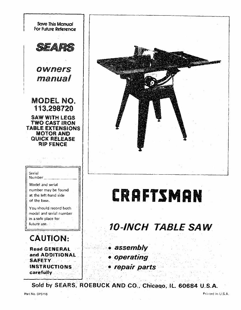
additional instructions forRiP TYPE CUTS
- NEVER use the miter gauge when ripping.- Use a push stick whenever the fence is 2 to 6
inches from the blade. Use an auxiliary fence andpush block whenever the fence must be within 2inches of the blade. (See "Basic Saw OperationUsing The Rip Fence" section.)
- Never rip anything shorter than 10" long.-When using a push stick or push block, the
trailing end of the _)oard must be square. A pushstick or block against an uneven end could slipoff or push the work away from the fence.
- A FEATHERBOARD can help guide the work-piece. See BASIC SAW OPERATION - USINGTHE RIP FENCE. Always use featherboards forany non-thru rip type cuts.
,__24"___
KERFS ABOUT !_,
5/16" APART IJ_4-1/2 '' _''_'.'-''_ 5
Before Starting-To avoid kickbacks and slips into the blade,
make surethe rip fence is parallel to the sawblade.- Check the antikickback pawls. (See BASIC SAW
OPERATION - USING THE RIP FENCE.) Thepawls must stop a kickback once it has started.Replace or sharpen antikickback pawls whenpoints become dul t.
- Plastic and composition (like hardboard) mater-ials may be cut on your saw. However, sincethese are usually quite hard and slippery, theantikickback pawls may not stop a kickback.Therefore, be especially careful in your set-upand cutting procedures.6. DON T FORCE TOOL. It will do the job bette
and,safer at its designed rate. Feed the workpieceinto the blade only fast enough to let it cut While cuttingwithout bogging down or binding. -To avoid kickbacks and slips into the bade
always push forward on the section of the work-

addiUonai instructions forCROSS CUT TYPE CUTS
Before starting- NEVER use the rip fence when crosscutting.- An auxiliary wood facing attached to the miter
gauge can help prevent workpiece twisting andthrowbacks. Attach it to the holes provided.Make the facing long enough and big enough tosupport your work, Make sure, however, it willnot interfere with the sawblade guard.
- Use jigs or fixtures to help hold any piece toosmall to extend across the full length of the mitergauge face during the cut. This lets you properlyhold the miter gauge and workpiece and hetpskeep your hands away from the blade.
While cutting- To avoid blade contact, always hold the miter
gauge as shown in the BASIC SAW OPERA-TIONS - USING THE MITER GAUGE.
BEFORE LEAVING THE SAW1. Turn the saw off.
2. Wait for blade to stop spinning.3. Make workshop child-proof. Lock the shop. Dis-
connect master switches. Remove the yellowswitch key. Store it away from children andothers not qualified to use the tool.
4. Unplug the saw.
GLOSSARY OF TERMS FOR WOODWORKING
Anti-Kickback Pawls (AKB)Device which, when properly maintained, is design-ed to stop the workpiece from being kicked back atthe operator during ripping operations.ArborThe shaft on which a cutting tool is mounted.CrosscutA cutting or shaping operation made across thewidth of the workpiece.DadoA non-through cut which produces a square sidednotch or trough in the workpiece.FeatherboardA device which can help guide workpqeces during nptype operations.
FreehandPerforming a cut without using a fence, miter gauge,fixture, hold down or other proper device to keep theworkpiece from twisting during the cut.GumA sticky, sap based residue from wood products.HeelMisalignment of the blade.KerrThe amount of material removed by the blade in athrough cut or the slot produced by the blade in anon-through or partial cut.KickbackAn uncontrolled grabbing and throwing of the work-piece back toward the front of the saw during a riptype operation.Leading EndThe end of the workp_ece which during a r_p typeoperation, is pushed into the cutting tool first.
MoldingA non-through cut which produces a special shapein the workpiece used for joining or decorat on.
Push StickA device used to feed the workpiece through the sawduring narrow ripping type operations and helpkeep the operator's hands well away from the blade.Push BlockA device used for ripping type operations too narrowto allow use of a push stick.RabbetA notch in the edge of a workpiece.ResinA sticky, sap base substance that has hardened.RippingA cutting operation along the length of the work-piece.Revolutions Per Minute (RPM)The number of turns completed by a spinning objectin one minute.Sawblade PathThe area of the workpsece or table top directly in linewith the part of the workpiece which wil! be. or hasbeen, cut by the blade.SetThe distance that the tip of the sawbJade tooth isbent (or set) outward from the face of the blade.
Throw-BackThrowing of pieces in a manner similar to a kickback.
Thru-SawingAny cutting operation where the blade extendscompletely through the thickness of the workplece.
Trailing EndThe workpiece end last cut bythe blade in a rippingoperation.WorkpieceThe item on which the cutting operation is beingdone_ The surfaces of a workpiece are commonlyreferred to as faces, ends, and edges.
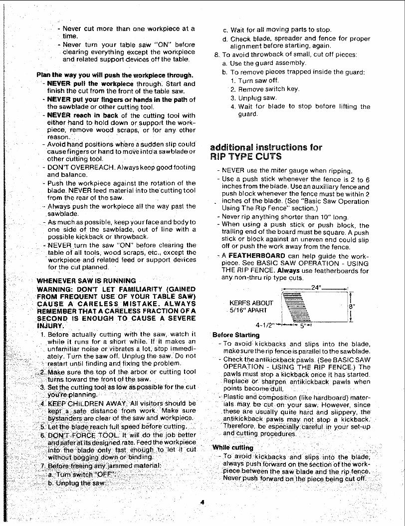
MOTOR SPECIFICATIONS ANThis saw is designed to use a 3450 RPM motor onmy.Do not use any motor that runs faster than 345,0RPM, It is wired for operation on 110-120 volts, 60Hz.. Alternating current. IT MUST NOT BECONVERTED TO OPERATE ON 230 VOLTS.
The Black and Red motor leads are connected toqu_ck connect tabs "A" and "g" on terminal board.
WARNING: Do not change any of these connec-tions with current on.
POWER LEAD T_
POWER LEAD'---_ i
BLACK
REEN"_ GROUND SCREW
IB RED
CAUTION: Do not use blower or washing machinemotors or any motor with an automatic resetoverload protector as their use may be hazardous.For replacement motor refer to parts list in thismanual.
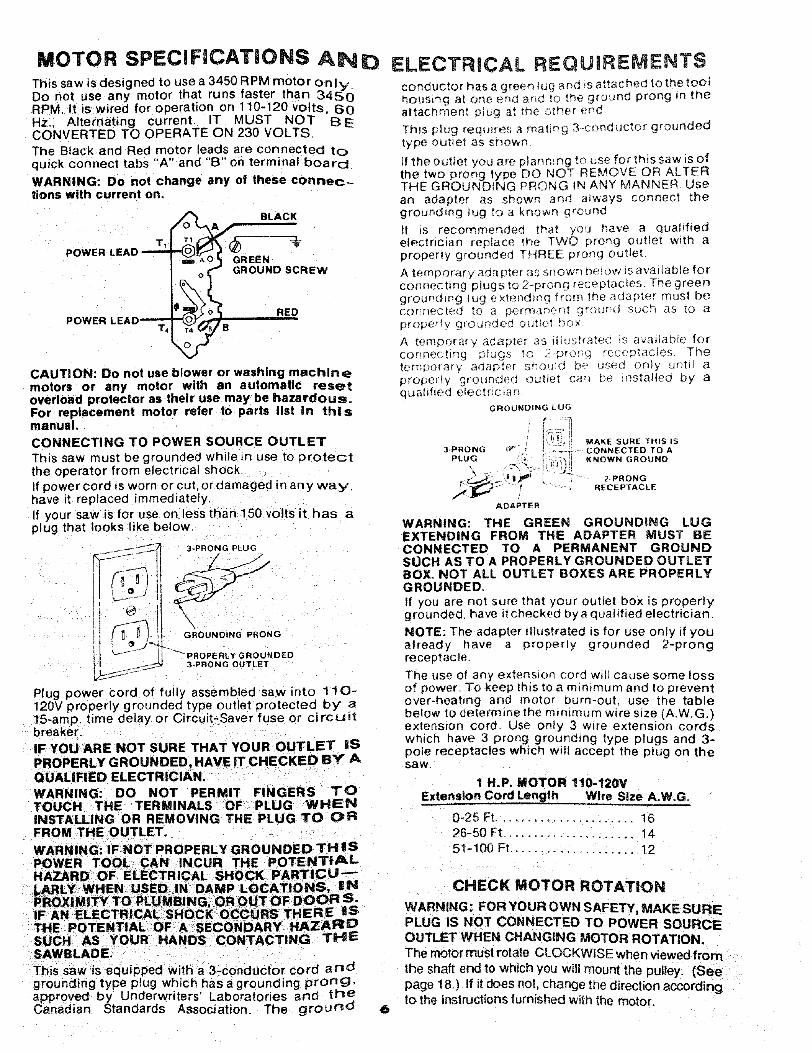
CONNECTING TO POWER SOURCE OUTLET
This saw must be grounded while in use to protectthe operator from electrical shockIf power cord is worn or cut, or damaged in any wa y,have it replaced immediately.
If your saw is for use on less than 150 volts it has aplug that looks like below.
3-PRONG PLUG
D
GROUNDING PRONG
GROUNDED3-PRDNG OUTLET
Plug power cord of fully assembled saw into 11 0-120V properly grounded type outlet protected by" a15-amp. time delay or Circuit-Saver fuse or ci rcuitbreaker.
IF YOU ARE NOT SURE THAT YOUR OUTLET iSPROPERLY GROUNDED, HAVE IT CHECKED BY AQUALIFIED ELECTRICIAN.
WARNING: DO NOT PERMIT FINGERS TOTOUCH THE TERMINALS OF PLUG WHENINSTALLING OR REMOVING THE PLUG TO CPRFROM THE OUTLET.
WARNING: IF NOT PROPERLY GROUNDED THISPOWER TOOL CAN INCUR THE POTENTIALHAZARD OF ELECTRICAL SHOCK PARTICU-
LARLY WHEN USED, IN DAMP LOCATIONS, iNPROX|MITY TO rk_,,,,_U'S NG, OR OUT OF I)OOR S.IF AN ELECTRICAL SHOCK OCCURS THERE ISTHE POTENTIAL OF A SECONDARY HAZARDSUCH AS YOUR HANDS CC)NTACTING THESAWBLADE.
This saw is equipped with a 3-conductor cord andgrounding type plug which has a grounding prong,approved by Underwriters' Laboratories and theCanadian Standards Association. The ground
ELECTRICAL REQUIREMENTSconductor has a green _ug _ nd _sattached to the tOOthousing a[ one _nd and _o the ground prong mtrleattachrnent plu_ at tr_e otf_e _ end
Th_s p_ug rerau_res a rnat_ng 3-cunductor groundedtype outlet as sr_owf_
If the outlet you are planmng tc _Jsefor this saw is ofthe two prong type DO NOT REMOVE OR ALTERTHE GROUNDING PRONG tN ANY MANNER. Usean adapter as strewn and a_ways connect thegrounding _ug to a known ground
it _s recommended that y'ou have a qualifiedelectrician replace fh_ TWO prong outlet with aproperly grounded THREE ;_rong outlet.
A temperat, ado pter _s snown De_(_WtS avaliab;e forconnechnq ptugs to 2-prong receptacles. The greenground ing Iug e ×ter_din(_ f torn the aoa [)terrn us| becorlr/f_,c|_(] t_ °) a _)ermanen! _!"©_rltJ S(;Ctq B5 [o a
proper_¥ _rt-_unded o(J'Je_ D()×
A temporary a(]aDter as _uusrrate(; m avadabte forconnecting plugs to 2-_)ronq receptacles Theternp_}rarv adapt_:l ShOUld De use(] only _,n_tl aproperW _gro_Jnded out_et can be m_taHed oy aqt_alified elec[nc_arl
GROUNDING LUG
MAK[ SURE THIS tS3PRO_NG _ " . _,_-. CONNECTED TD A
PLUG "* I' ;_")_iKNOWN GROUND
ADAPTER
WARNING: THE GREEN GROUNDING LUGEXTENDING FROM THE ADAPTER MUST BECONNECTED TO A PERMANENT GROUNDSUCH AS TO A PROPERLY GROUNDED OUTLETBOX, NOT ALL OUTLET BOXES ARE PROPERLYGROUNDED.
If you are not sure that your outlet box is properlyg rounded, have it checked by a qualified electrician.
NOTE: The adapter dlustrated is for use only if youalready have a properly grounded 2-prongreceptacle
The use of any extension cord will cause some lossof power_ To keep this to a minimum and to preventover-heating and motor burn-out use the tablebelow to determine the mm_mum w_re size (A.W.G.}extension cord Use only 3 wire extension cordswhich have 3 prong grounding type plugs and 3-pole receptacles which will accept the plug on theS_W.
1 H.P. MOTOR 110-120V
Extension Cord Length Wire Size A.W.G.
0-25 Ft...................... 16
26-50 Ft ..................... 14
51-100 FI .................... 12
CHECK MOTOR ROTATION
WARNING: FORYOUROWN SAFETY, MAKESURE
PLUG IS NOT CONNECTED TO POWER SOURCEOUTLET WHEN CHANGING MOTOR ROTATION.
The motor must rotate CLOCKWISE when viewed from
the shaft end to which you wilt mount the pulley. (See
page 18.) tf it does not, change the direction accordingto the instructions furnished with the motor.

CONTENTS
WARRANTY ............................................................... 2SAFETY INSTRUCTIONS FOR TABLE SAWS ......... 2
Rip Type Cuts ........................................................ 4Cross Cut Type Cuts ............................................. 5
GLOSSARY OF WOODWORKING TERMS .............. 5MOTOR SPECIFICATIONS AND ELECTRICAL
REQUIREMENTS .................................................. 6UNPACKING AND CHECKING CONTENTS ............ 7
Tools Needed ......................................................... 7List of Loose Parts ................................................. 8
AS SEM SLY ................................................................ 9Installing Handwheels ............................................ 9Checking Table Insert ............................................ 9Checking Blade Squareness to Table ................... 9Assembling Steel Legs ........................................ 10Mounting Saw ...................................................... 10Attaching Table Extensions ................................. 11Mounting Switch .................................................. 12Installing Rip Fence Guide Bars .......................... 12Aligning Rip Fence ............................................... 14Adjusting Rip Scale Pointer ................................. 16Installing Blade Guard ......................................... 16Mounting the Motor .............................................. 18installing Belt Guard ............................................. 20Plugging in Motor ................................................. 21
GETTING TO KNOW YOUR SAW .......................... 22On-Off Switch ....................................................... 22Elevation Handwheel ........................................... 23Tilt Handwheel ................................................... 23Tilt Lock Handle ................................................... 23Rip Fence ............................................................ 23Miter Gauge ......................................................... 23Blade Guard ......................................................... 23Table Insert .......................................................... 23
Removing and Installing Sawblade ...................... 24Exact-I-Cut ........................................................... 24
BASIC SAW OPERATION ....................................... 25Work Helpers ....................................................... 25Safety Instuctions for Basic Saw Operation ......... 26Using the Miter Gauge ......................................... 29
Crosscutting ..................................................... 29Repetitive Cutting ............................................ 30Miter Cutting .................................................... 30Bevel Crosscutting ........................................... 31Compound Miter Cutting .................................. 31
Using the Rip Fence ............................................ 31Ripping ............................................................ 32Bevel Ripping .................................................. 32Using Featherboards for Thru-Sawing ............ 32Resawing ......................................................... 35Cutting Panels ................................................. 35Using Featherboards for Non-Thru Sawing ..... 35Rabbeting ........................................................ 36Ploughing and Molding .................................... 36Dadoing ........................................................... 36Melding Cutting ................................................ 37
ADJ USTM ENTS ....................................................... 37Miter Gauge ......................................................... 37Heeling Adjustment or Parallelism of Sawblade
to Miter Gauge Groove ................................... 38Blade Tilt or Squareness of Blade to Table ......... 39Tilt Mechanism ..................................................... 41
MAINTENANCE ....................................................... 41LUBRICATION ......................................................... 42RECOMM ENDED ACCESSORIES ........................ 42TFIOUBLESHOQTING ............................................. 43REPAIR PARTS ....................................................... 45
UNPACKING
NEEDED
_- ,_-,=-- _ Medium Screwdriver(_ Hammer Small Screwdriver
__ .................... Wrenche3/8 in. 7/16 in.1/2 in. 9/16 in.
Combination Square 3/4 in.
Separate all parts from packing materials and checkeach one with the illustration and the list of LooseParts to make certain all items are accounted for,before discarding any packing material.
If any parts are missing, do not attempt to assemblethe table saw, plug in the power cord or turn theswitch on until the missing parts are obtained andare installed correctly.
Remove the protective oil that is applied to the tabletop and edges of the table, Use any ordinary house-hold type grease and spot remover.
AND CHECKING CONTENTSCOMBINATION SOUARE MUST BE TRUE.
DRAW LIGHT LINE ONBOARD ALONG THIS EDGE. '_
I
L_
STRAIGHT EDGE OF BOARD3/4" THICK. THIS EDGE MUST
BE PERFECTLY STRAIGHT.
SHOULD BE NO GAP OR OVERLAPHERE WHEN SQUARE IS FLIPPED
O_R tNDOTTEDPosmoN.WARNING: TO AVOID FIRE OR HEALTH HAZARD,NEVER USE GASOLINE, NAPTHA OR SIMILARHIGHLY VOLATILE SOLVENTS.Apply a coat of automobile wax to the table.
Wipe all parts thoroughly with a clean, dry cloth.
WARNING: FOR YOUR OWN SAFETY, NEVERCONNECT PLUG TO POWER SOURCE OUTLETUNTIL ALL ASSEMBLY STEPS ARE COMPLETE,AND YOU HAVE READ AND UNDERSTAND THESAFETY AND OPERATIONAL INSTRUCTIONS,
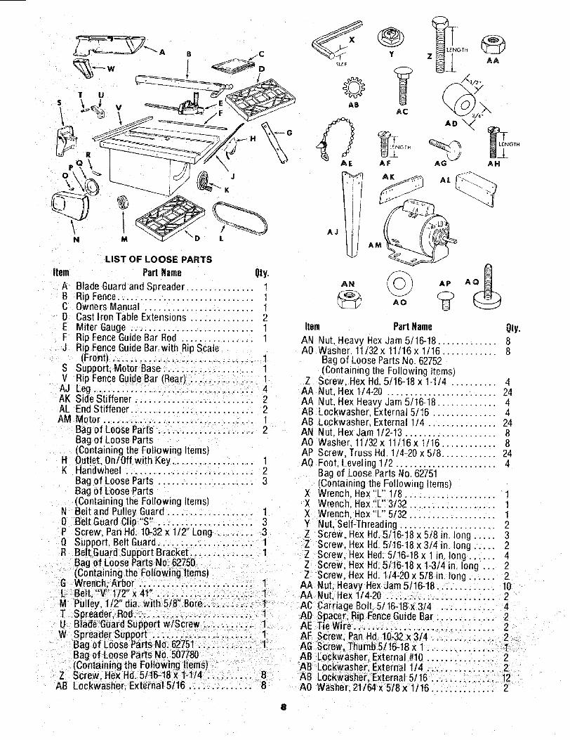
LIST OF LOOSE PARTS
item Part Name Qty.
A Blade Guard and Spreader ............... 1B Rip Fence. ............................. 1C Owners Manual . ....................... 1D Cast Iron Table Extensions .............. 2E Miter Gauge ........................... 1F Rip Fence Guide Bar Rod ................ 1J Rip Fence Guide Bar with Rip Scale
(Front) .............................. 1S Support, Motor Base .................... 1V Rip Fence Guide Bar (Rear) .............. 1AJ Leg ............................... 4AK Side Stiffener ........................... 2AL End Stiffener ........................... 2AM Motor ................................. 1
Bag of Loose Parts ..................... 2Bag of Loose Parts(Containing the Following Items)
H Outlet. 0n/0ff with Key .................. 1K Handwheel ............................ 2
Bag of Loose Parts ..................... 3Bag of Loose Parts(Containing the Following Items)
N Belt and Pulley Guard ................... 10 Belt Guard Clip "S' . ......................P Screw, Pan Hd. 10-32 x 1/2" Long ........ 3Q Support, Belt Guard ..................... 1R Belt Guard Support Bracket .............. 1
Bag of Loose Parts No. 62750(Containing the Following Items)
G Wrench: Arbor ..; ............. 1L Belt, V 1/2 x41 .................. ...
Z AA
AO "_
AG AH
M Pulley, 1/2" dia. with 5t8" Bore... ........T Spreader, Rod.. ........................ 1U Blade Guard Support wlScrew ........... 1W Spreader Support .......: ........ _.... 1
Bag of Loose Parts No. 62751 ............ 1Bag of Loose Parts No. 507780(Containing the Following Items)
Z Screw, He;<Hd; 5/16-t8 x 1-1/4 ... : ...... 8AB Lockwasher. External 5/16 .............. 8
AL
Item Part Name
AN Nut. Heavy Hex Jam 5/16-18 ............. 8A0 Washer. 11/32 x 11t16 x 1/16 ............ 8
Bag of Loose Parts No 62752(Containing the Following Items)
Z Screw. Hex Hd. 5/!6-18 x 1-1/4 .......... 4AA Nut, Hex 1/4-20 ........................ 24AA Nut, Hex Heavy Jam 5/!6-18 ............. 4AB Lockwasher External 5/16 .............. 4AB Lockwasher External 1/4 ............... 24AN Nut. Hex Jam 1/2-13 .................... 8A0 Washer, 11/32 x 11/16x t/16 ............ 8AP Screw, Truss Hd 1/4-20 x 5/8 ............ 24AQ Foot Leveling 1/2 ...................... 4
Bag of Loose Parts No. 62751(Containing the Following Items)
X Wrench, Hex"L" 1/8 ....................X Wrench. Hex "L" 3/32 ................... 1X Wrench. Hex"L" 5/32 ................... 1Y Nut, Self-Threading ..................... 2Z Screw. Hex Hd. 5/16-18 x 5/8 in. long ..... 3Z Screw, Hex Hd. 5/16-18 x 3/4 in. long ...... 2Z Screw, Hex Hed. 5/16-18 x t n. long ...... 4g Screw. Hex Hd. 5/16-18 x 1-314 in. long .. 2Z Screw, Hex Hd. 114-20 x 518 in. long ...... 2
AA Nut, Heavy Hex Jar_ 5/16-18 ............. 101 AA Nut, Hex 1/4-20 ................. 21 AC Carriage Bolt. 5/16-18 x 3/4 ............ 4
AI) Spacer, Rip Fence Guide Bar ............. 2AE T_eWire ........ i ...................... 2AF Screw; Pan Hd 10-32 x 3/4 ............ 2AG Screw, Thurnb5/16-18x 1 ............... 1AB Lockwasher External #10 ....... 2A8 Lockwasher External 1/4 .............. 2AB Lock_vasher,:External 5/16 .......... 12A0 W'asher. 21/64 x 5/8 x 1/16 .............. 2
8
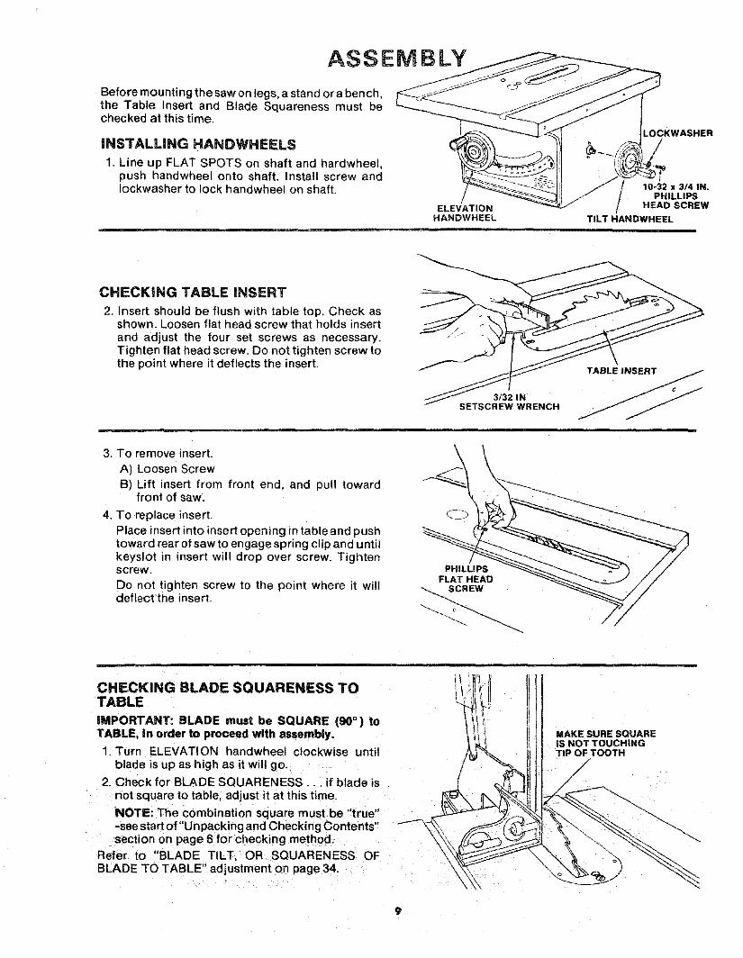
ASSEMBLY
Before mounting the saw on legs, a stand or a bench,the Table Insert and Blade Squareness must bechecked at this time.
iNSTALLING HANDWHEELS
1. Line up FLAT SPOTS on shaft and hardwheel,push handwheel onto shaft. Install screw andIockwasher to lock handwheet on shaft.
.OCKWASHER
/10-32 x 314 IN.
PHILLIPSELEVATION HEAD SCREW
HANDWHEEL TILT HANDWHEEL
= =
CHECKING TABLE iNSERT
2. Insert should be flush with table top, Check asshown. Loosen flat head screw that holds insertand adjust the four set screws as necessary.Tighten flat head screw. Do not tighten screw tothe point where it deflects the insert.
3/32 INSETSCREW WRENCH
3. To remove insert.A) Loosen Screw
B) Lift insert from front end, and pull towardfront of saw.
4. To replace insert.Place insert into insert opening in table and pushtoward rear of saw to engage spring clip and untilkeyslot m insert will drop over screw. Tightenscrew.
Do not tighten screw to the point where it willdeflect the insert.
FLAT HEAD _"__ //
CHECKING BLADE SQUARENESS TOTABLE
iMPORTANT: BLADE must be SQUARE (90° ) toTABLE, in order to proceed with assembly.
1. Turn ELEVATION handwhee! clockwise untilblade is up as high as it will go.
2. Check for BLADE SQUARENESS... if blade isnot square to table, adjust it at this time.
NOTE: The combination square must be "true"-see start of "Un packing and Checking Contents"section on page 6 for checking method.
Refer to "BLADE TILT, OR SQUARENESS OFBLADE TO TABLE" adjustment on page 34.
MAKE SURE SQUAREiS NOT TOUCHINGTiP OF TOOTH
/

ASSEMBLING STEEL LEGS
From among the loose parts, find the followingHardware:
24 Truss Head Screws, 1/4-20 x 5/8 in. long (top ofscrew is rounded)24 Lockwashers, 1/4 in, External Type (approx.dia. of hote 1/4 in.)24 Hex Nuts, 1/4-20 (approx. dia. of hole 1/4 in.)8 Hex Nuts, 1/2-13 (approx. dia. of hole 1/2 in.)
4 Leveling feet
Assemble the legs as shown..
1. Insert the Truss Head Screws through the holesin the legs, then through the holes in the stiffen-ers MAKE SURE THE SCREWS TO THROUGHTHE HOLES IN THE SIDE STIFFENERSMARKED "X'"
2. Install the Iockwashers.. _screw on the nuts butdo not tighten until completely assembled.
3. Install leveling feet. .-,+_71!2 IN. HEX NUTS
......... LEVELING FOOT
MOUNTING SAW
1. From among the loose parts, find the followinghardware:
4 Hex Head Screws, 5/16-18 x 1-1/4 in. long.4 Hex Nuts, 5/16-18 (approx. dia. of hole 5/16 in.)4 Lockwashers, 5/16 in. External Type (approx.dia. of hole, 5/16 in.]8 Flat Washers, (dia. of hole 11/32 in.)
2. Ptase saw on legs so that holes in bottom of sawline up with holes in top of legs.
3. Install screws, washers, Iockwashersand nuts asshown.
tf you mount the saw on any other bench, make surethat there is an opening in the top of the bench thesame size as the opening n the bottom of the saw sothat the sawdust can drop through. Recommendedworking height is 33 to 37 inches from the top of thesaw table to the floor.
SAW BASE ]_[
HEXHEAOSC.EW
FLAT WASHE R'----_ _ tl
END f _ ""STIFFENER--_L
FLAT WASHER ]/
7/16 DIA. HOLES
/_-- ................. 11-1/4 .....................
,o,I ............'_{' OPENIN G
\, /I
13
2-3/4
/
16 _\
/
\;/ \
FRONT OF SAW
NOTE: All dimensions in inches
13
Q__3_
112
IO
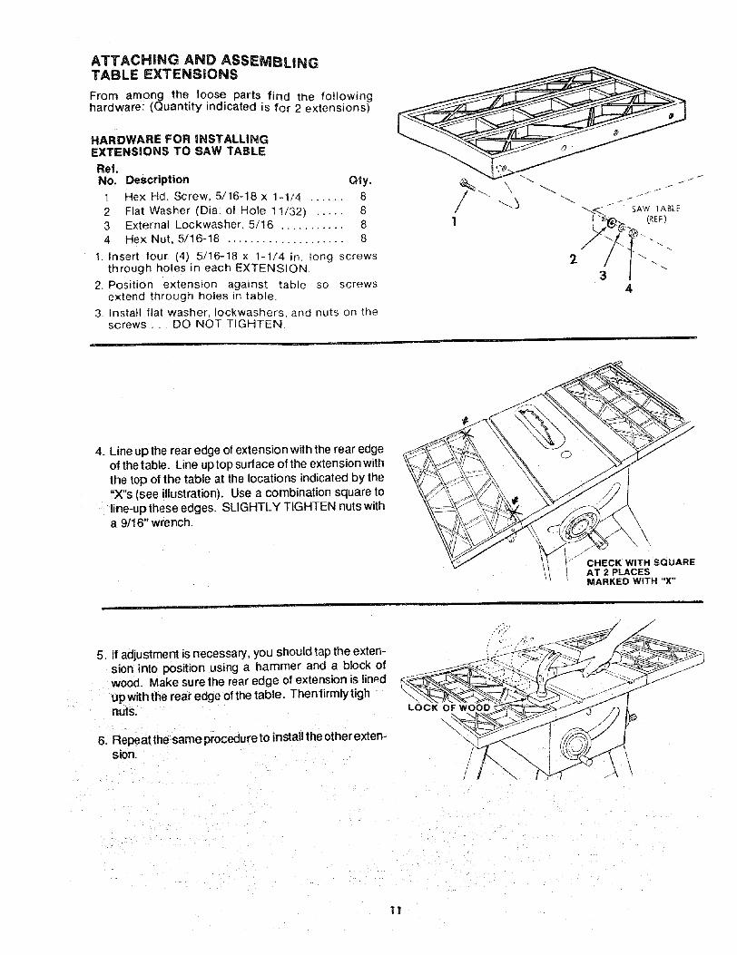
ATTACHING AND ASSEMBLINGTABLE EXTENSIONS
From among the loose parts find the followinghardware: (Quantity indicated is for 2 extensions)
HARDWARE FOR INSTALLINGEXTENSIONS TO SAW TABLE
Ref.No. Description Qty,
1 Hex Hdl Screw, 5/16-18 x 1-1/4 ...... 8
2 Flat Washer (Dia: of Hole 11/32) ..... 83 External Lockwasher, 5/16 ........... 84 He× Nut, 5/16-18 .................... 8
1. |nsert four (4) 5/16-18 x 1-1/4 in. tong screwsthrough holes in each EXTENSION.
2. Position extension against table so screwsextend through holes in table.
3_ Install flat washer, Iockwashers, and nuts on thescrews... DO NOT TIGHTEN.
4. Line up the rear edge of extension with the rear edgeof the table. Line u0 top sudace of the extension withthe top of the table at the locations indicated by the"X"s (see illustration). Use a combination square toline-up these edges. SLIGHTLY TIGHTEN nutswitha 9/16" wrench.
_'_ JCHECK WITH SQUARE
AT 2 PLACESMARKED WITH "X"
5. If adjustment is necessary, you should tap the exten-sion into position using a hammer and a block ofwood. Make sure the rear edge of extension is linedup withthe rear edge of the table. Thenfirmlytighnuts.
6. Repeatthe sameprocedureto installthe otherexten-sion.
LOCK OF WOOD "
\
11

MOUNTING SWITCH
1. From among loose parts find the following:
2 Hex Head Screws, 5/16-18 x 3/4 in. long2 Flatwashers (dia. of hole 21/64 in.)2 External Lockwashers
2 Hex Nuts, 5/16-18
2. Insert two 3/4 inch screws through two flatwashers then through holes in switch.
3. Insert screws through holes eight and ten in frontfence guide bar as illustrated
4. Install two Iockwashers and nuts Tighten nuts,
INSTALLING RiP FENCE GUIDE BARS
1. From among the loose parts find the followinghardware:
2 Hex Head Screws. 5/16-18 x 1-3/4 in. long
2 Hex Head Screws, 5/16-18 x 1 in. long4 External Lockwashers, 5/16 in.(approx. dia. of hole 5/16 in.)4 Hex Nuts, 5/16-18(approx. dia. of hole 5/16 in.)2 Spacers. 3/4 in. dia. x 1/2 in. long
2 Self-threading nuts1 Fence Guide Bar Rod
2. Lay guide bars on saw table.NOTE: The various holes in the bar allows themto be positioned on this saw and also makesthem adaptable to other models.
3. Insert a 1-3/4 inch long screw through theTHIRD hole IN THE FRONT BAR as illustrated... Insert another 1-3/4 inch long screwthroughthe SEVENTH hole in bar.
4. Place spacers on screws,
JAM NUT5116-18
7TH HOLE
t_---_ WASHER
IHEX HEAD SCREW
5/16-18 x 3/4 IN.
3RD HOLE
LEFT SIDE OFFRONT GUIDE BAR
(GUIDE BAR IS TO BETURNED END FOR ENEAFTER SCREWS ARE
INSTALLED)
HEX HEADSCREW
5/16-18 x 1-3/4 IN
5. Turn front bar end for end and insert boltsthrough holes in middle and on right sides offront of saw table as illustrated . . . installIockwashers and nuts. DON'T SCREW NUTSON ALL THE WAY, just get them started on thescrews.
4TH OR 5TH 2ND HOLE
_k"_ SELF-THR EAD|NG NUT HOLE
6. Inse[t 1 in. long screws in SECOND and _ - /"
FOURTH or FI FTH holes of rear bar and attachto table the same way as front bar.
7. Insert ends of FEKICE GUIDE BAR ROD Fthrough holes in bars as illustrated. BAR RODNOTE: The ends of the ROD are not threaded ...the SELl: THREADING NUTS wil! cut threadson the rod as they are screwed on. Just start nuts conto ends of rod.
]2
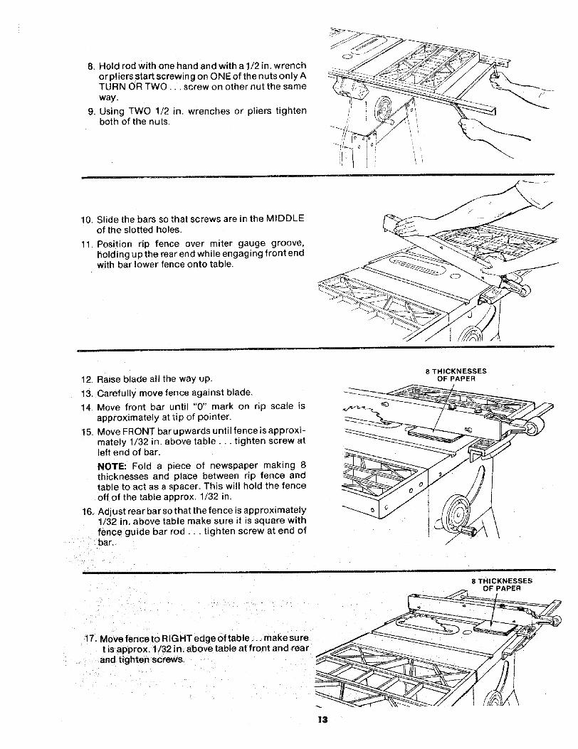
8. Hold rod with one hand and with a 1/2 in. wrenchor pliers start screwing on ONE of the nuts only ATURN OR TWO... screw on other nut the sameway.
9. Using TWO 1/2 in. wrenches or pliers tightenboth of the nuts.
10. Slide the bars so that screws are in the MIDDLEof the slotted holes.
11, Position rip fence over miter gauge groove,holding up the rear end while engaging front endwith bar lower fence onto table.
12. Raise blade all the way up.
13. Carefully move fence against blade.
14. Move front bar until "0" mark on rip scale isapproximately at tip of pointer.
15. Move FRONT bar upwards until fence is approxi-mately 1/32 in. above table.., tighten screw atleft end of bar.
NOTE: Fold a piece of newspaper making 8thicknesses and place between rip fence andtable to act as a spacer. This wil! hold the fenceoff of the table approx. 1/32 in.
16. Adjust rear bar so that the fence is approximately1/32 in. above table make sure it is square withfence guide bar rod.., tighten screw at end ofbar.
8 THICKNESSESOF PAPER
8 THICKNESSESOF PAPER
17. Move fence to RIGHT edge of table.., make suret is approx. 1/32 in. above table at front and rear
and tighten screws.
13

ALIGNING RiP FENCE
The fence should slide easily along the bars andalways remain in alignment (parallel to sawbladeand miter gauge grooves).
The alignment is maintained by a spring underneaththe fence which bears against the front guide bar.
TO movethe fence, loosen the lock handle and graspthe fence with one hand at the front.
For very close adjustments, grasp theguide bar withboth hands and move the fence with your thumbs.
\
SELF ALIGNING ADJUSTMENT
Place fence on saw but DO NOT LOCK IT.
Move the R EAR END of the fence slightly to the rightor left. , . when you release it, the fence should"spring" back to its original position.If i| does not, the spring pressure must be IN-
1. Looser, the screws.
2 Move Spring slightly toward front of fence.
14

If fence does not slide easily along the bars, thepressure of the spring can be REDUCED.
1. Loosen the screws.
2. Move spring slightly toward rear of fence . . .tighten screws.
WARNING: TO AVOID INJURY FROM JAMS ORKICKBACK, BE SURE TO PROPERLY ADJUST ANDPUSH LOCK LEVER ALL THE WAY DOWN UNTILTHE LEVER RESTS ON THE STOP BEFORE USINGTHIS RIP FENCE.
SPRING
SCREWS,
SLIDE SPRING TOADJUST PRESSURE
RIP FENCE LOCK LEVER ADJUSTMENT
The ripfence lock lever when locked down, should holdthe rip fence securely, it should not be difficultto pushdown and lock.
If lock lever does not lock fence securely...1. Raise lock lever.
2. Tighten the aOjusting nut using a small screwdriveruntil the lever, when locked, holds the rip fencesecurely.
If lock lever is difficult to push down...
1. Raise lock lever.
2. Loosen the adjusting nut using a small screwdriveruntil the lever is easy to push down and holds the ripfence securely.
AD3USTING NUT
FENCE HEAD
RiP FENCE ALIGNMENT ADJUSTMENT
The riptence must be PARALLEL with the sawblade andMiter Gauge grooves_..Move fence until it is along sideof groove. Do NOT LOCK IT. It should be parallel togroove. If it is not;
1. Loosen the two "Hex Head Screws".
2. Hold fence head tightly against bar.., move end offence so that it is parallel with groove.
3. Alternately tighten the screws.
4. Recheck alignment.
5. Repeat steps as needed.
HEX SCREWS
FENCE HEAD
\\
15

ADJUSTING RiP SCALE POINTER
1. Turn ELEVATION HANDWHEEL clockwise untHblade is up as high as it will go,IMPORTANT: BLADE must be SQUARE (90 ° ) toTABLE. in order to ALIGN rip fence.
2. Position fenceon right side of sawblade so that ittouches the sides of the teeth.., tighten lockhandle.
3. Loosen screw holding the pointer . . . adjustpointer so that it points to "0" .. tighten screw.
NOTE: If you cannot adjust pointer so that itpoints to "0", loose n the screws holding the fro ntguide bar and move the guide bar.
POINTER
_-K HANDLE
INSTALLING BLADE GUARD
1_ From among the loose parts, find:2 Hex Head Screws, 1/4-20 x 5/8 in. long3 Hex Head Screws, 5/16-18 x 5/8 in. long2 Hex Head Screws, 5/16-18 x 1 in. long2 Hex Nuts, 1/4-20 (approx. dia. of hole 1/4 in.)2 Lockwashers, 1/4 in. External Type
(approx. dia. of hole 1/4 in.)2 Lockwashers, 5/16 in. External Type
(approx. dia. of hole 5/16 in.)1 ThumbscrewBlade Guard SupportSpreader SupportSpreader Rod
2. Before installing the blade guard, you mustcheck theheeling adjustment (parallelism of sawblade to mitergauge groove). The procedure for making this checkand adjusting it are found inthe "Adjustments" sect ionof this manual. Refer to "Heeling Adjustment orParallelism ol Saw Blade to Miter Gauge Groove".
BLADE GUARD _,_ ''-_
SUPPORT 5/16-18\ HEX HD.
5/16ol 8 X: \
HEX HD.SCREW
5/16 IN.LOCKWASHERS
5/16-18 X 5/8 INHEX HD. SCREWS
3. Lower the blade.
4. Screw the MOTOR BASE CLAMP SCREWS partway into cradle. Screw the 5t16-18 x 5/8 inch HexHead screw into the blade guard support.
5. Attach BLADE GUARD SUPPORT... DO NOTTIGHTEN SCREWS,r
THUMB SCR EW//__
6 Insert SPREADER ROD intoSPREADER SUPPORT SPREADER
ti;thleP_nitlits int° n°tch" Insert THUMBSCREW and sFRLFATcESPREADER
(INTO SUPPORT), SUPPORT
,,

7. Slide SPREADER ROD into BLADE GUARDSUPPORT until end of ROD is even With edge ofSUPPORT . . . Tighten Hex Head _crew insupport,
8. Attach SPREADER to SPREADER SUPPORT sothat the edge of the spreader is even with theedge of the spreader support. •, tighten screws.
9. Raise ANTIKICKBACK PAWL (hoSd it in placewith a piece of masking tape)
•.. align spreader SQUARE to table
• . . Tighten both 5/16-18 x ! in. HEX HEADSCREWS.
1/4-20 HEXHD. SCREW
1/d IN. LOCKWASHER-_/4~20 HEX NUT
sPREADER EDGEEVEN WiTH SPREADER
SUPPORT EDGE
END OF RODEVEN WITH EDGE
OF SUPPORT
F
t5/16-18 X 1 IN,
HEX HD. SCREWS
10. Raise blade all the way up... make sure it issquare with table.
I1. Raise Blade Guard ... lift up both ANTIKICK-BACK PAWLS.,. insert one of the SETSCREWWRENCHES in the notches to hold the pawls outof the way.
12. Lay blade of square or other straightedge along-side of blade.
13. Loosen Hex Head Screw in BLADE GUARDSUPPORT and move spreader so that it touchesblade of square.,, tighten screw•
14. NOTE: The spreader is now square with the tableand approximately in line with the sawb_ade. Thespreader requires further adjustment to align itPARALLEL to the blade and in the MIDDLE of thecut (KERF) made by the sawblade. SCREW
15.IMPORTANT: To work property, the SPREADERmust always be PARALLEL to the sawblade andadjusted so the cut workpiece will pass on eitherside at the spreader without binding or skewingto the side.
NOTE: The spreader is thinner than the width ofthe cut (KERF) made by the 8awblade by approxi-mately six thicknesses of paper.
KERF WOOD
iw
SPREADER
LOOKING DOWN ON SAW
BLADE
//
17
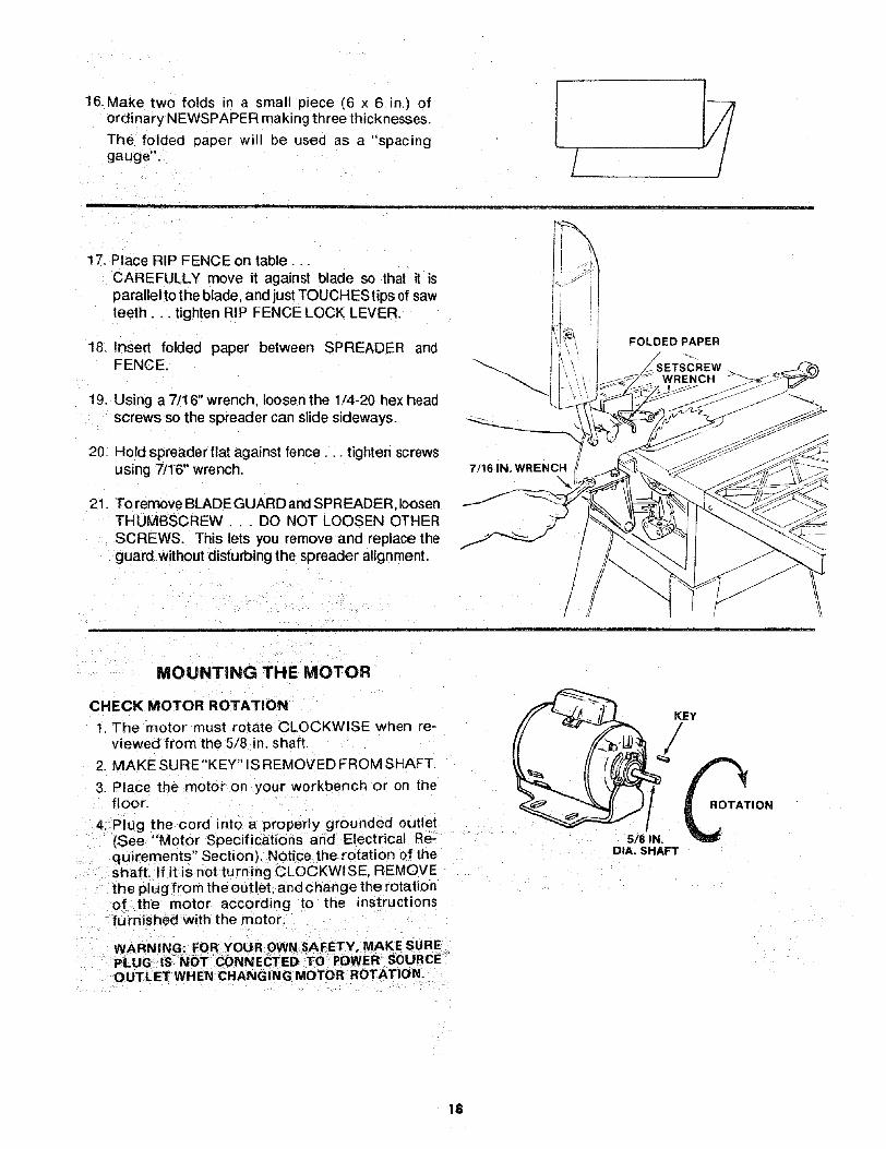
16.Make two folds n a small piece (6 x 6 in,) ofordinary NEWSPAPER making three thicknesses.
The folded paper will be used as a "spacinggauge". / I
17. Place RIP FENCE on table...CAREFULLY move it against blade so that it isparalletto the blade and just TOUCHES tips of sawteeth.., tighten RIP FENCE LOCK LEVER.
18. Insert folded paper between SPREADER andFENCE,
19. Using a 7/16" wrench, loosen the 1/4-20 hex headscrews so the spreader can slide sideways.
20. Hold spreader flat against fence.., tighten screwsusing 7/16" wrench.
21. To remove BLADE GUARD and SPREADER, loosenTHUMBSCREW . DO NOT LOOSEN OTHERSCREWS. This lets you remove and replace theguard without disturbing the spreader alignment.
7/16 IN, WRENCH
\
FOLDEDPAPER
MOUNTING THE MOTOR
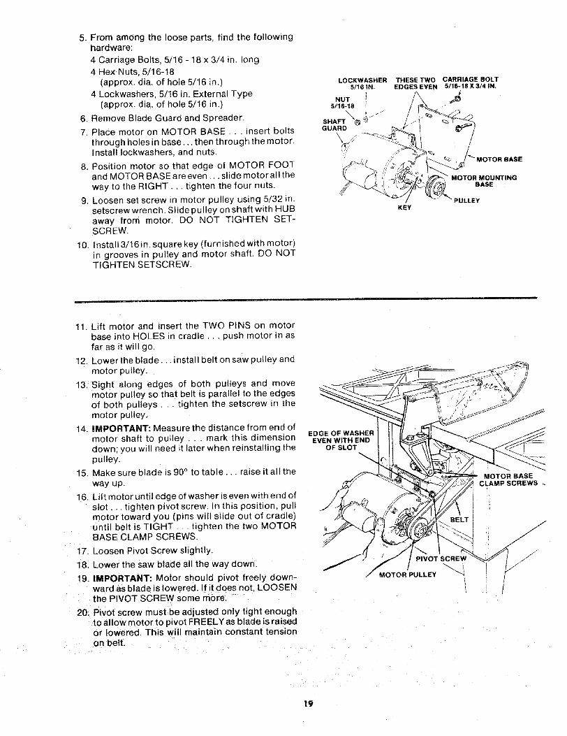
CHECK MOTOR ROTATION
1. The motor must rotate CLOCKWISE when re-viewed from the 5/8 in. shaft,
2. MAKE SURE"KEY" IS REMOVED FROM SHAFT
3. Place the motor on your workbench or on thefloor.
4. Plug the cord into a properly grounded outlet(See "Motor Specifications and Electrical Re-quirements" Section). Notice the rotation of theshaft. If it is not turning CLOCKWISE, REMOVEthe plug from the outlet, and change the rotationof the motor according to the instructionsfurnished with the motor,
KEY/
J
5/8 IN. _ION
DIA, SHAFT
OUTLET WHEN CHANGING MOTOR ROTATION.
18
5. From among the loose parts, find the followinghardware:
4 Carriage Bolts, 5/16 - 18 x 3/4 in. long4 Hex Nuts, 5/16-18
(approx. dia. of hole 5/t6 in.)4 Lockwashers, 5/16 in. External Type
(approx. dia. of hole 5/16 in.)
6. Remove Blade Guard and Spreader.
7. Place motor on MOTOR BASE,.. insert boltsthrough holes in base.., then through the motor.Install Iockwashers, and nuts.
8. Position motor so that edge of MOTOR FOOTand MOTOR BASE are even ... slide motor all theway to the RIGHT... tighten the four nuts.
9. Loosen set screw in motor pulley using 5/32 in.setscrew wrench, Slide pulley on shaft with HUBaway from motor. DO NOT TIGHTEN SET-SCREW.
10. Install 3/16 in. square key (furnished with motor)in grooves in pulley and motor shaft. DO NOTTIGHTEN SETSCREW.
LOCKWASHER5/16 IN.
NUT l5/16-18
SHAFT _'_ ,,_"GUARD
THESE TWOEDGES EVEN
KEY
CARRIAGE BOLT5./16-18 X 3/4 IN.
MOTOR MOUNTINGBASE
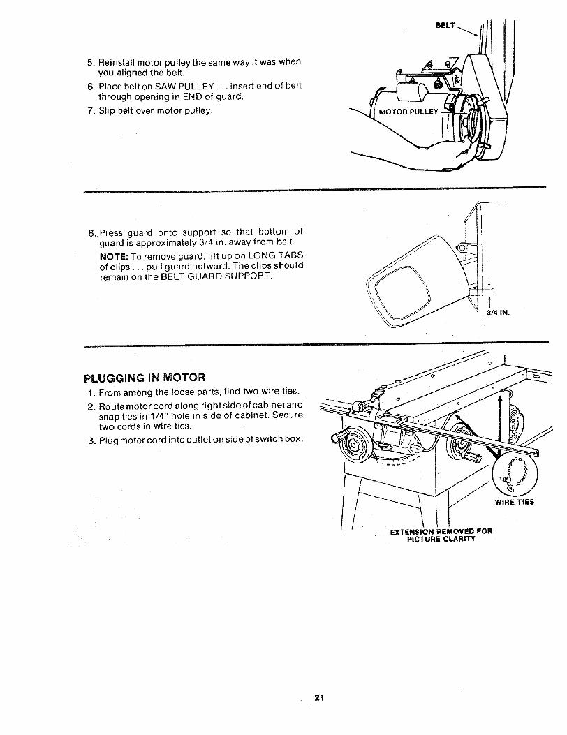
11. Lift motor and insert the TWO PINS on motorbase into HOLES in cradle,., push motor in asfar as it will go.
12. Lower the blade.., install belt on saw pulley andmotor pulley.
13, Sight along edges of both pulleys and movemotor pulley so that belt is parallel to the edgesof both pulleys.., tighten the setscrew in themotor pulley.
14. IMPORTANT: Measure the distance from end ofmotor shaft to pulley . . . mark this dimensiondown: you will need it later when reinstalling thepulley.
15, Make sure blade is 90° to table., raise it al! theway up.
16. Lift motor until edge of washer is even with end ofslot., tighten pivot screw. In this position, pullmotor toward you (pins will slide out of cradle)until belt is TIGHT.. tighten the two MOTORBASE CLAMP SCREWS.
17. Loosen Pivot Screw slightly.
18, Lower the saw blade all the way down.
19. IMPORTANT: Motor should pivot freely down-ward as blade is lowered. If it does not. LOOSENthe PIVOT SCREW some more.
20. Pivot screw must be adjusted only tight enoughto allow motor to pivot FREELY as blade is raisedor lowered. This will maintain constant tensionon belt.
EDGE OF WASHEREVEN WITH END
OF SLOT
PIVOTSCREW
MOTOR PULLEY ""
1
" MOTOR BASECLAMP SCREWS
19

21. Loosen the two MOTOR CLAMP SCREWS oneach end of motor. Rotate the motor so that theCAPACITOR COVER is on top.., tighten thescrews. The ventilation holes are now facingdownward which will help prevent sawdust fromentering motor.
CAPACITORCOVER
\\
VENTILATIONHOLES
\MOTOR
CLAMP SCREW
(BOTH ENDS)
I
iNSTALLING BELT GUARD
1. Remove the belt and motor pulley.
2. Screws furnished with guard are "self threading"• . screw them into holes in BELT GUARDSUPPORT BRACKET, then remove them.
3. Position BELT GUARD SUPPORT BRACKETand BELT GUARD SUPPORT as shown andinstall the screws •,. make sure motor shaft is inCENTER of hole in SUPPORT.
BELT GUARD
\PIVOT
SCREW
_""J TWO HOLES CLOSEST
BELT GUARD (SUPPORT BRACKET
SCREW\
BELT GUARD SUPPORT
CENTERED
OPENING/
4. Install three CLIPS (furnished with guard) 90°apart starting with one clip at the end of theguard as shown.. , LONG END of clip facing BELTGUARDAWAY from you.
LONG END
2O
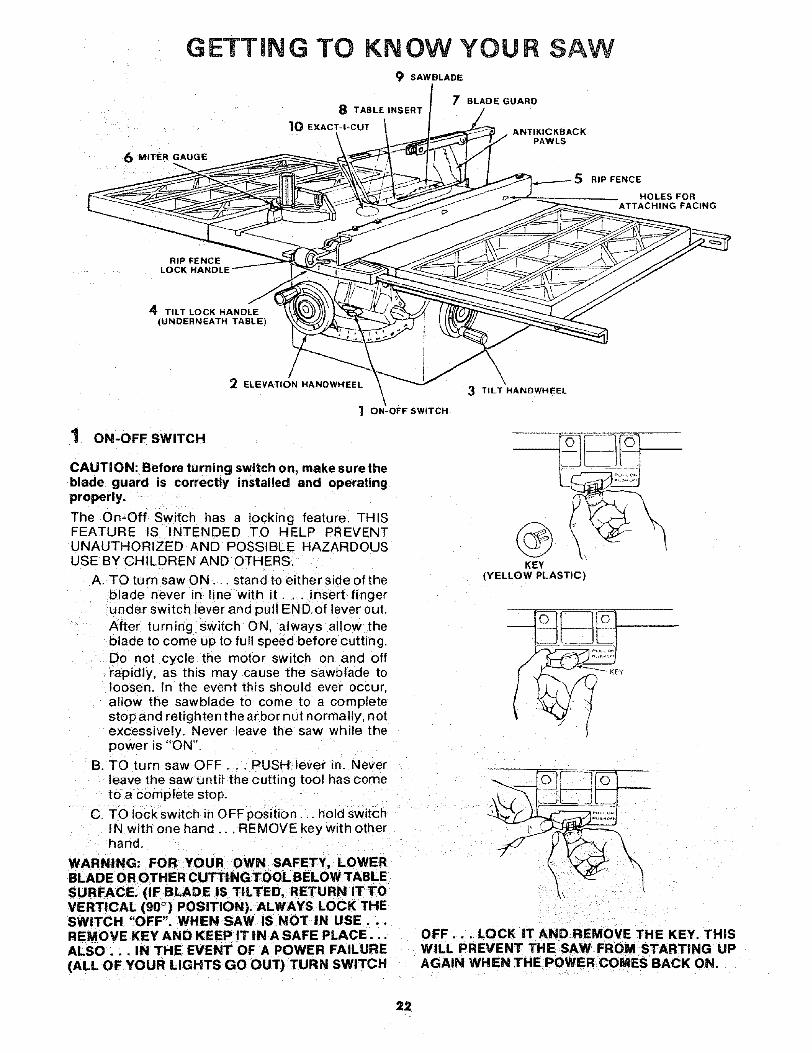
5. Reinstall motor pulley the same way it was whenyou aligned the belt.
6. Place belt on SAW PULLEY... insert end of beltthrough opening in END of guard,
7. Slip belt over motor pulley.
BELT
8. Press guard onto support so that bottom ofguard is approximately 3/4 in. away from belt,
NOTE: To remove guard, lift up on LONG TABSof clips.., pull guard outward, The clips shouldremain on the BELT GUARD SUPPORT.
13/4 IN.
PLUGGING IN MOTOR
1. From among the loose parts, find two wire ties.
2. Route motor cord along right side of cabinet andsnap ties in 1/4" hole in side of cabinet. Securetwo cords in wire ties,
3. Plug motor cord into outlet on side of switch box,
WIRE TIES
EXTENSION REMOVED FORPICTURE CLARITY
21
GETTING TO KNOW YOUR SAW9 SAWBLADE
8 TABLE INSERT
10 EXACT-I-CUT
6 MITER GAUGE
RIP FENC_
LOCK HANDLE _ _,_
4 TILT LOCK HANDLE -\_.C(UNDERNEATH TABLE)
12 ELEVATION HANDWHEEL
\"_ ON-OFF SWITCH
7 BLADE GUARD
ANTIKICKBACKPAWLS
\3 TILT HANDWHEEL
ON-OFF SWITCH
CAUTION: Before turning switch on, make suretheblade guard is correctly installed and operatingproperty.
The On-Off Switch has a locking feature. THISFEATURE IS INTENDED TO HELP PREVENTUNAUTHORIZED AND POSSIBLE HAZARDOUSUSE BY CHILDREN AND OTHERS.
A. TO turn saw ON... stand to either side of theblade never in line with it... insert fingerunder switch lever and pull END of lever out.After turning switch ON, always allow theblade to come up to full speed before cutting.Do not cycle the motor switch on and offrapidly, as this may cause the sawblacle toloosen. In the event this should ever occur,allow the sawblade to come to a completestop and retighten the arbor nut normally, notexcessively. Never leave the saw while thepower is "ON'!.
B. TO turn saw OFF.. PUSH lever in. Neverleave the saw until the cutting tool has cometo a complete stop.
C. TO lock switch in OFF position.., hold switchIN with one hand ... REMOVE key with otherhand.
RIP FENCE
HOLES FORATTACHING FACING
KEY(YELLOW PLASTIC)
= ",, ;o,....
WARNING: FOR YOUR OWN SAFETY, LOWERBLADE OR OTHER CUTTING TOOL BELOW TABLESURFACE. (IF BLADE IS TILTED, RETURN IT TOVERTICAL (90 ° ) POSITION), ALWAYS LOCK THESWITCH "OFF". WHEN SAW iS NOT IN USE...REMOVE KEY AND KEEP IT iN A SAFE PLACE... OFF... LOCK IT AND REMOVE THE KEY. THISALSO... IN THE EVENT OF A POWER FAILURE WiLL PREVENT THE SAW FROM STARTING UP(ALL OF YOUR LIGHTS GO OUT) TURN SWITCH AGAIN WHEN THE POWER COMES BACK ON.
22
2 ELEVATION HANDWHEEL...elevates or lowersthe blade, Turn clockwise to elevate.,, counter-clockwise to lower.
3 TILT HANDWHEEL... tilts the blade for bevelcutting. Turn clockwise to tilt toward left . . .counterclockwise to tilt toward right.
When the blade is tilted to the LEFT as far as itwill go, it should be at 45° to the table and thebevel pointer should point 45°.
NOTE: There are LIMIT STOPS inside the sawwhich prevent the blade from tilting beyond 45°to the LEFT and 90° to the RIGHT. (See "Adjust-ments" section "Blade Tilt, or Squareness ofBlade to Table").
4 TILT LOCK HANDLE.. : locks the blade in thedesired tilt position. To loosen, turn counter-clockwise. Push handle in and turn itto anotherposition if necessary in order to tighten orloosen.
5 RIP FENCE... is locked in place by pushing thelock lever down until the lever rests on the stop.To move the fence, lift the lock lever and graspthe fence with one hand at the front.Holes are provided in the rip fence for attachinga wood facing when using the dado head, ormolding head.Select a piece of smooth straight wood approx.3/4 in. thick and the same size as the rip fence.Attach it to the fence with three Round Head #10Wood Screws 2 in. long. To remove the facing,loosen the screws, slide the facing forward andpull the screws through the round holes.
WOOD FACINGt
o q
\ / ///\ ROUND HEAD ./
# 'tO WOOD SCREWS
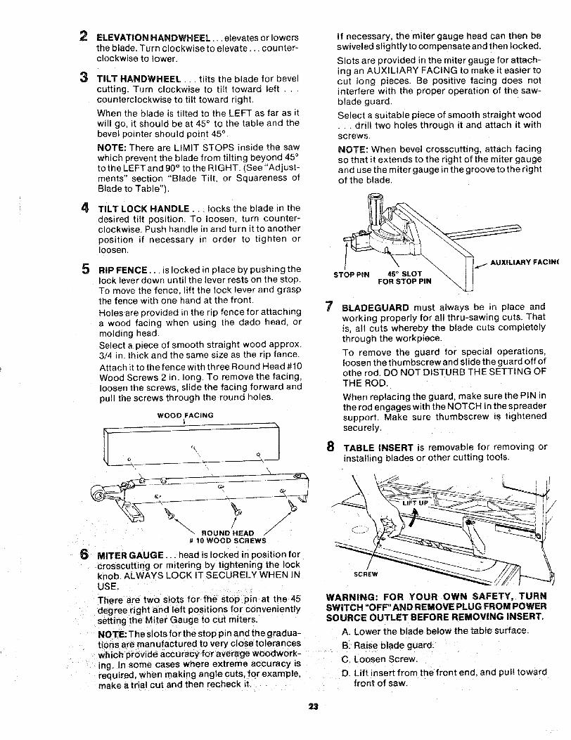
6 MITER GAUGE... head is locked in position forc rosscutting or mitering by tightening the lockknob ALWAYS LOCK IT SECURELY WHEN INUSE.
There are two slots for the stop pin at the 45degree right and left positions for convenientlysetting the Miter Gauge to cut miters.
NOTE: The slots for the stop pin and the gradua-tions are manufactured to very closetoleranceswhich provide accuracyfor average woodwor k-ing. In some cases where extreme accuracy isrequired, when making angle cuts, for example,make a trial cut and then recneck it.
If necessary, the miter gauge head can then beswiveled slightly to compensate and then locked.
Slots are provided in the miter gauge for attach-ing an AUXILIARY FACING to make it easier tocut long pieces. Be positive facing does notinterfere with the proper operation of the saw-blade guard.
Select a suitable piece of smooth straight wood•.. drill two holes through it and attach it withscrews.
NOTE: When bevel crosscutting, attach facingso that it extends to the right of the miter gaugeand use the miter gauge in the groove to the rightof the blade.
STOP PiN 45 _ SLOTFOR STOP PIN
IXtLIARY FACIN(
7 BLADEGUARD must always be in place andworking properly for all thru-sawing cuts. Thatis, all cuts whereby the blade cuts completelythrough the workpiece.
To remove the guard for special operations,loosen the thumbscrew and slide the guard off ofothe rod. DO NOT DISTURB THE SETTING OFTHE ROD.
When replacing the guard, make sure the PIN inthe rod engages with the NOTCH inthe spreadersupport. Make sure thumbscrew is tightenedsecurely.
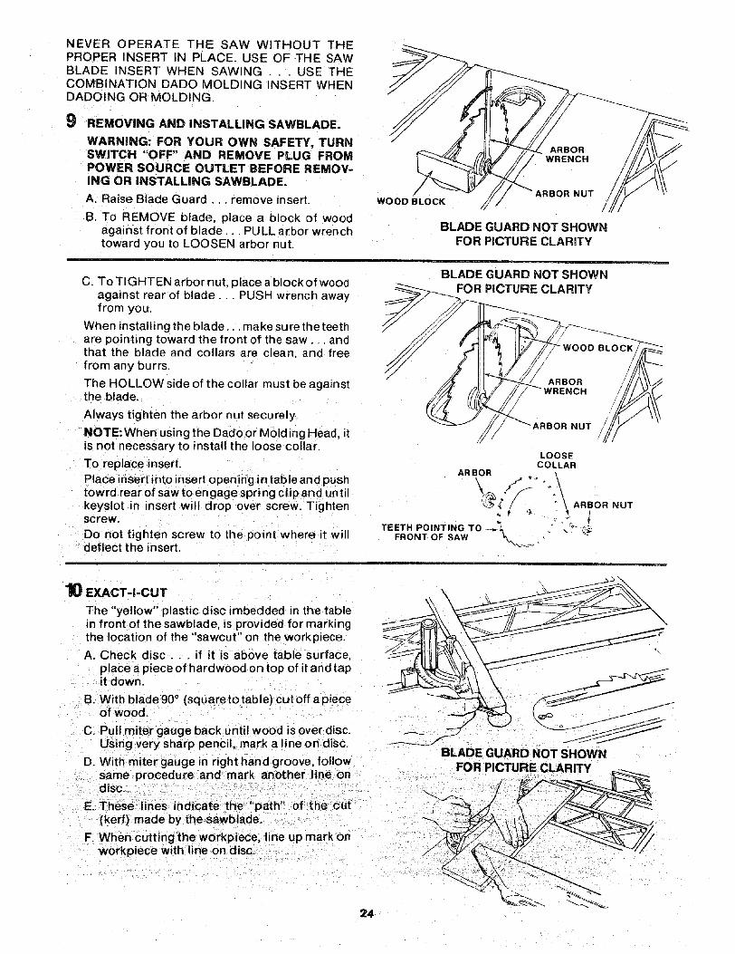
8 TABLE INSERT is removable for removing orinstalling blades or other cutting tools.
\
SCREW
WARNING: FOR YOUR OWN SAFETY, TURNSWITCH "OFF" AND REMOVE PLUG FROM POWERSOURCE OUTLET BEFORE REMOVING INSERT.
A. Lower the blade below the table surface.
B. Raise blade guard.
C. Loosen Screw.
D. Lift insert from the front end, and pull towardfront of saw.
NEVEROPERATETHE SAWWITHOUT THEPROPERINSERTIN PLACE.USEOFTHE SAWBLADEINSERTWHENSAWING. . . USETHECOMBINATrONDADOMOLDINGINSERTWHENDADOINGORMOLDING.
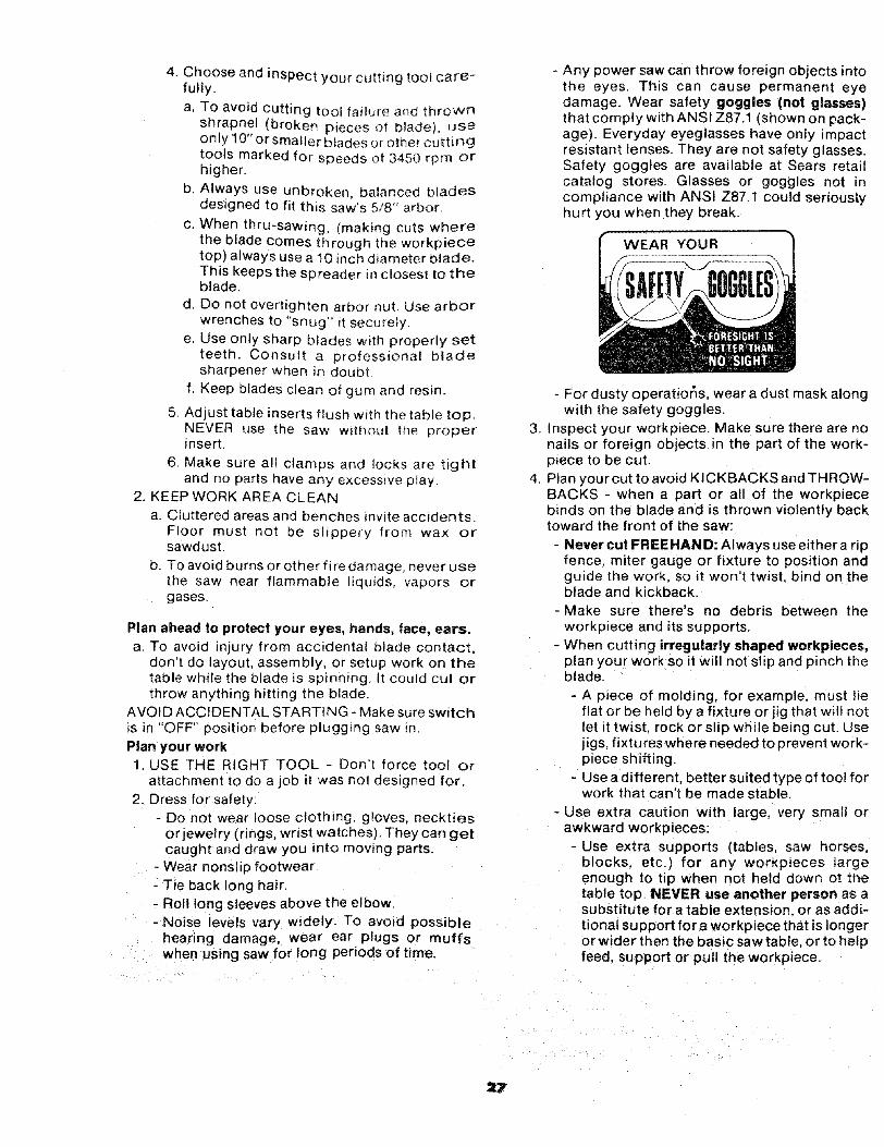
9 REMOVING AND iNSTALLING SAWBLADE.
WARNING: FOR YOUR OWN SAFETY, TURNSWITCH "OFF" AND REMOVE PLUG FROMPOWER SOURCE OUTLET BEFORE REMOV-ING OR INSTALLING SAWBLADE.
A. Raise Blade Guard... remove insert.
B. To REMOVE blade, place a block of woodagainst front of blade... PULL arbor wrenchtoward you to LOOSEN arbor nut.
ARBORWRENCH
/!
WOOD BLOCKARBOR NUT
BLADE GUARD NOT SHOWNFOR PICTURE CLARITY
C. To TIGHTEN arbor nut, place a block of woodagainst rear of blade... PUSH wrench awayfrom you.
When installing the blade.., make sure the teethare pointing toward the front of the saw.. andthat the blade and collars are clean, and freefrom any burrs.
The HOLLOW side of the collar must be againstthe blade.
Always tighten the arbor nut securely.
NOTE: When using the Dado or Mold ing Head, itis not necessary to install the loose collar.
To replace insert.
Place insert into insert opening in table and pushtowrd rear of saw to engage spring clip and untilkeyslot in insert will drop over screw. Tightenscrew.
Do not tighten screw to the point where it willdeflect the insert.
BLADE GUARD NOT SHOWNPICTURE CLARITY
NUT
LOOSECOLLAR
ARBOR
TEETH POINTING TO _ _T" -_;-FRONT OF SAW _'_ .
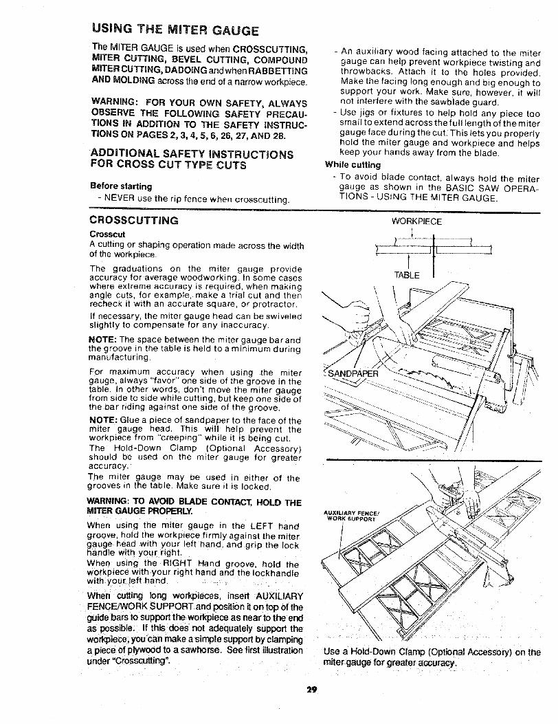
10 EXACT-I-CUT
The "yellow" plastic disc imbedded in the tablein front of the sawblade, is provided for markingthe location of the "sawcut" on the workpiece.
A. Check disc.., if it is above table surface,place a piece of hardwood on top of it and tapit down.
B. With blade90 ° (squaretotable} cutoff apieceof wood.
C. Pull miter gauge back until wood is over disc.Using very sharp pencil, mark a line on disc.
D. With miter gauge in right hand groove, followsame procedure and mark another line ondisc.
..... ,i 71 tE. These lines ndcate the path of the cu(kerf) made by the sawblade.
F. When cutting the workpiece, line up mark onworkpiece with line on disc.
8LADEGUARDNOTS.OW.
24

BASIC SAW OPERATION
WORK HELPERS
Before cutting any wood on your saw, study all of the"Basic Saw Operations".Notice that in order to make some of the cuts, it isnecessary to use certain devices "Work Helpers" likethe Push Stick, the Push Block and the AuxiliaryFence/Work Support, which you can make yourself.
After you have made a few practice cuts, make upthese "helpers" before starting any projects. Makethe "Push Stick" first.
SLIGHTLY LESS THANTHICKNESS OF WORKPIECE
UP TO 3/8"
1-5/8
"-_i _" 1/245° NOTCH
PUSH STICK AND PUSH BLOCK
Make the Push S'_ick using a piece of 1 x 2, or rip onefrom a wide board, say 11-1/2 in. wide, and set the ripfence 9-7/8 in. from the sawblade.
Make the Push Block using a piece of 3/8 in. and 3/4in. plywood.
The small piece of wood 3/8 in. x 3/8 in. x 2-1/2 in.should be GLUED to the plywood... DO NOT USENAILS. This isto prevent dulling the sawblade in theevent you mistakingly cut into the push block.
Position the handle in the center of the plywood andfasten together with glue and woodscrews.
NOTE: All dimensions in inches
PUSH STICK
THESE EDGES MUSTBE PARALLEL
4-3/4 \3/4 PLYWOOD
3/8
NOTE: All dimensions in inchesPUSH BLOCK
3/83/8 PLYWOOD
25

AUXILIARY FENCE/WORK SUPPORT
Make one using a piece of 3t8 in. and 3/4 in. Plywood.Fasten together with glue and wood screws.
NOTE: Since the Push Block is used with the AuxiliaryFence, the 4-3/4 in. dimensions must be held identicalon both the pieces.
THIS FACE ANDEDGE MUST BEPARALLEL
3/8 PLYWOOD
NOTE All dimension in qches_"'_ 5"1/2
AUXILIARY FENCE!WORK SUPPORT
1-1/4
AUXILIARY PANEL WORK SUPPORTMake using a piece of 3/4" and 3/8" plywood. Fastentogether with glue and wood screws. Use this auxiliarypanel work support only when cutting large panels thatrequire the rip fence to be positioned past the exposedside of the extension,
3/4 PLYWOOD
3-5/8
FACE & EDGEMUST BE "_ .IPARALLEL _"
/ 2""3/8 PLYWOOD
NOTE: All dimension in inches
AUXILIARY PANEL/WORK SUPPORT
SAFETY INSTRUCTIONS FOR
BEFORE EACH USE:
1. Inspect your saw.a. To avoid injury from accidental starting, unplug
the saw, turP, the switch off and remove theswitch key before raising or removing theguard, changing the cutting tool, changingthe setup or adjusting anything.
b. Check for alignment of moving parts, bindingof moving parts, breakage of parts mounting,and any other conditions that may affect theway it works. If any part is missing, bent, orbroken in any way, or any electrical parts don'twork properly, turn the saw off and unplug thesaw.
c. Replace damaged, missing, or failed partsbefore using the saw again.
d. Use the sawblade guard, spreader, and anti-
piece). Make sure the pawls work properly.
BASIC SAW OPERATIONS
Make sure the spreader is in line with thesawblade,REMOVE ADJUSTING KEYS ANDWRENCHES. Form habit of checking for andremoving keys and adjusting wrenches fromtool before turning _ton.To avoid injury from jams, slips or thrownpieces (kickback and throwback):
1. USE ONLY RECOMMENDED ACCESSO-RIES (See page 42) - Follow the instructionsthat comewiththeaccessories. Usingotheraccessories may be dangerous.
2. Choose the right blade or cutting accessoryfor the matedal and the type of cutting youplan to de.
3, Never use grinding wheels, abrasive cut-off
wire wheels or buffing wheel. They can flyapart explosively.
4, Choose and inspect your cutting tool care-fully.
a, To avoid cutting toot failure a_d thrownshrapnel (broken pieces of blade), Ljseonly 10" or Smaller blades or other cuttingtools marked for speeds o_ 3450 rpm orhigher.
b. Always use unbroken, balanced bladesdesigned to fit this saw's 5/8" arbor.
c. When thru-sawing, (making cuts wherethe blade comes through the workpiecetop) always use a 10 inch diameter blade.This keeps the spreader in closest to theblade.
d Do not overtighten arbor nut. Use arborwrenches to "snug" it securely,
e. Use only sharp b_ades with properly setteeth. Consult a professional bladesharpener when in doubt.
f, Keep blades clean of gum and resin.
5. Adjust table inserts flush with the table top.NEVER use the saw without the properinsert,
6, Make sure all clamps and locks are tightand no parts have any excessive play.
2. KEEPWORK AREA CLEAN
a. Cluttered areas and benches invite accrdents.
Floor must not be slippery from wax orsawdust.
b. To avoid burns or other fi re damage, never usethe saw near flammable liquids, vapors or
gases,
Plan ahead to protect your eyes, hands, lace, ears.
a. To avoid injury from accidental blade contact,don't do layout, assembly, or setup work on thetable while the blade is spinning It could cut or
throw anything hitting me blade.
AVOID ACCIDENTAL STARTING - Make sure switch
is in "OFF" position before plugging saw Jn
Plan your work1 USE THE RIGHT TOOL - Don't force toot or
attachment to do a job it was not designed for.
2. Dress for safety:
- Do not wear loose ctothing, gloves, neckties
or jewelry (rings, wrist watches). They can getcaught and draw you into moving parts.
- Wear nonslip footwear
- Tie back long hair.
- Roll long sleeves above the elbow.
- Noise levels vary widely. To avoid possible
heanng damage, wear ear plugs or muffswhen using saw for long periods of time.
- Any power saw can throw foreign objects intothe eyes, This can cause permanent eyedamage. Wear safety goggles (not glasses)that comply with ANSI Z87.1 (shown on pack-age). Everyday eyeglasses have only impactresistant lenses. They are not safety glasses,Safety goggles are available at Sears retailcatalog stores. Glasses or goggles not incompliance with ANSI Z87.1 could seriouslyhurt you when they break.
WEAR YOUR
- For dusty operatior_s, wear a dust mask alongwith the safety goggles,
3. Inspect your workpiece. Make sure there are nonails or foreign objects in the part of the work-piece to be cut.
4. Plan your cut to avoid KICKBACKS and THROW-BACKS - when a part or all of the workpiecebinds on the blade and is thrown violently backtoward the front of the saw:
- Never cut FREEHAN D: Always use either a ripfence, miter gauge or fixture to position andguide the work, so it won't twist, bind on theblade and kickback.
-Make sure there's no debris between theworkp_ece and its supports.
- When cutting irregularly shaped workpieces,plan your work so it will not slip and pinch theblade.- A piece of molding, for example, must lie
flat or be held by a fixture or jig that wiil notlet it twist, rock or slip while being cut. Usejigs, fixtures where needed to prevent work-piece shifting.
- Use a different, better suited type of tool forwork that can't be made stable.
- Use extra caution with large, very small orawkward workpieces:
- Use extra supports (tables saw horses,blocks, etc.) for any wor_pieces largeenough to tip when not held down ot thetable top. NEVER use another person as asubstitute for a table extension, or as addi-tional support fora workpiece that is longeror wider then the basic saw table or to helpfeed. support or pul! the workpiece.
:=7

- Never c0nfinethe piece being cut off.Thatis, the piece NOT against the fence, mitergauge or fixture. Never hold it. clamp it.touch it, or use length stops against it. Itmust be free to move. If confined, it couldget wedged against the blade and cause akickback or throwback.
- Never cut more than one workpiece at atime.
-Never turn your table saw "ON" beforeclearing everything except the workpieceand related support devices off the table.
Plan the way you will push the workpiece through.- NEVER pull the workpiece through. Start and
finished the cut from the fron of the tabel saw.
- NEVER put your fingers or hands in the path ofthe sawblade or other cutting tool.
- NEVER reach in back of the cutting tool witheither hand to hold down or support the work-piece, remove wood scraps, or for any otherreason.
-Avoid awkward operations and hand positionswhere a sudden slip couldcause fingers or handto move into a sawblade or other cutting tool.
- DON'T OVERREACH. Always keep good footingand balance.
- Push the workpiece against the rotation of theblade. NEVER feed material into the cutting toolfrom the rear of the saw.
- Always push the workpiece all the way past thesawblade.
- As much as possible, keep your face and body toone side of the sawblade, out of line with apossible kickback or throwback.
- NEVER turn the saw "ON" before clearing thetable of all tools, wood scraps, etc, except theworkpiece and related feed or support devicesfor the cut planned.
WHENEVER SAW IS RUNNING
WARNING: DON'T LET FAMILiARiTY (GAINEDFROM FREQUENT USE OF YOUR TABLE SAW)CAUSE A CARELESS MISTAKE. ALWAYSREMEMBER THAT A CARELESS FRACTION OF ASECOND IS ENOUGH TO CAUSE A SEVEREINJURY.
1. Before actually cutting with the saw. watch itwhile it runs for a short while. If it makes anunfamiliar noise or vibrates excessively, stopimmediately, Turn the saw off_ Unplug the saw.Do not restart until finding and correcting tl_eproblem.
2. Make sure the top of the arbor or cuthng toolturns toward the front of the saw.
3. Set the cutting tool as low as possible for othe cutyou're _)tanning.
4. KEEP CHILDREN AWAY. All visitors should bekept a safe distance from work. Make surebystanders are clear of the saw and workp_ece.
5, Let the blade reach full speed before cutting.6. DON'T FORCE TOOL. It will do the job better
and safer at its designed rate. Feed the work p=eceinto the blade only fast enough to let it cutwithout bogging down or binding.
7 Before freeing any jammed material:a. Turn switch "OFF"
D Unplug the saw.c. Wait for all moving parts to stop.d. Check blade, spreader and fence for proper
alignment before starting, again.8. T(_ avoid throwback of small, cut off pieces:
a. Use the guard assembly.b. To remove pieces trapped inside the guard:
1. Turn saw off.
2. Remove switch key.
3. Unplug saw.4. Wait for blade to stop before lifting-the
guard
BEFORE LEAVING THE SAW1. Turn saw off2. Wait for blade to stop spinning.3. Make workshop child-proof. Lock the shop. Dis-
connect master switches. Remove the yellowswitch key. Store it away from children andothers not qualified to use the tool.
4. Unplug the saw.
USING THE MITER GAUGE
The MITER GAUGE is used when CROSSCUTTING,MITER CUTTING, BEVEL CUTTING, COMPOUNDMITER CUTTING, DADOING and when RABBETTINGAND MOLDING across the end of a narrow workpiece.
WARNING: FOR YOUR OWN SAFETY, ALWAYSOBSERVE THE FOLLOWING SAFETY PRECAU-TIONS IN ADDITION TO THE SAFETY INSTRUC-TIONS ON PAGES 2, 3, 4, 5, 6, 26, 27, AND 28.
ADDITIONAL SAFETY iNSTRUCTiONSFOR CROSS CUT TYPE CUTS
Before starting
- NEVER use the rip fence when crosscutting.
- An auxiliary wood facing attached to the mitergauge can help prevent workpiece twisting andthrowbacks. Attach it to the holes provided.Make the facing long enough and big enough tosupport your work. Make sure, however, it willnot in.terfere with the sawblade guard.
- Use jigs or fixtures to help hold any piece toosmall to extend across the full length of the mitergauge face during the cut. This lets you properlyhold the miter gauge and workpiece and helpskeep your hands away from the blade.
While cutting
- To avoid blade contact, always hold the mitergauge as shown in the BASIC SAW OPERA-TIONS- USING THE MITER GAUGE.
CROSSCUTTING
Crosscut
A cutting or shaping operation made across the widthof the workpiece.
The graduations on the miter gauge provideaccuracy for average woodworking. In some caseswhere extreme accuracy is required, when makingangle cuts, for example, make a trial cut and thenrecheck it with an accurate square, or protractor.
If necessary, the miter gauge head can be swiveledslightly to compensate for any inaccuracy.
NOTE: The space between the miter gauge barandthe groove in the table is held to a minimum duringmanufacturing
For maximum accuracy when using the mitergauge, always "favor" one sade of the groove in thetable. In other words, don't move the miter gaugefrom side to side while cutting, but keep one side ofthe bar riding against one side of the groove.
NOTE: Glue a piece of sandpaoer to the face of themiter gauge head. This will help prevent theworkpiece from "creeping" while it is being cut.The Hold-Down Clamp (Optional Accessory)sP]ould be used on the miter gauge for greateraccuracy.
The miter gauge may _e used in either of thegrooves m the table. Make sure it is locked.
WARNING: TO AVOID BLADE CONTACT, HOLD THEMITER GAUGE PROPERLY.
When using the miter gauge in the LEFT handgroove, hold the workpiece firmly against the mitergauge head with your left hand. and grip the Fockhandle with your r_ght.
When using the RIGHT Hand groove, hold theworkpiece with your right hand and the !ockhandlewith your left hand
When cutting long workpieces, insert AUXILIARYFENCE/WORK SUPPORT and position it on top of the
guide bars to support the workpiece as near to the end
as possible. If this does not adequately support the
workpiece, you can make a simple support by clamping
a piece of plywood to a sawhorse. See first illustrationunder "Crosscutting.
\
\
PER
AUXILIARY FENCE!WORK SUPPORT
ir
WORKPIECE
1
l I Jt l-2TABLE
\\
\
Use a Hold-Down Clamp (Optional Accessory) on themiter gauge for greater accuracy,
29
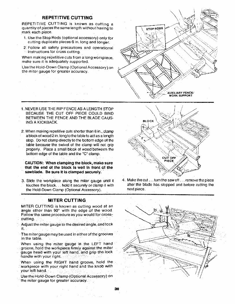
REPETITIVE CUTTING
REPETITIVE CUTTING is known as cutting aquantity of pieces the same length without having tomark each piece.
1. Use the Stop Rods (optional accessory) only forcutting duplicate pieces 6 in. long and longer,
2. Follow all safety precautions and operationalinstructions for cross cutting,
When making repetitive cuts from a long workpiece,make sure it is adequately supported.
Use the Hold-Down Clam p (Optional Accessory) onthe miter gauge for greater accuracy,
_'_ AUXILIARY FENCE/WORK SUPPORT
1. NEVER USE THE RIP FENCE AS A LENGTH STOPBECAUSE THE CUT OFF PIECE COULD BINDBETWEEN THE FENCE AND THE BLADE CAUS-ING A KICKBACK.
2. When making repetitive cuts shorter than 6 in,. clampa block of wood 2 in. tong to the table to act as a lengthstop. Do not clamp directly to the bottom edge of thetable because the swivel of the clamp will not gripproperly. Place a small blcok of wood between thebottom edge of the table and the "C" clamp.
CAUTION: When clamping the block, make surethat the end of the block Is well in front of thesawblade. Be sure it is clamped securely.
3. Slide the workpiece along the miter gauge until ittouches the block, hold it securely or clamp it withthe Hold-Down Clamp (Optional Accessory).
\\\
BLOCK
4. Make the cut ... turn the saw off.., remove the pieceafter the blade has stopped and before cutting thenext piece.
MITER CUTTING
MITER CUTTING is known as cutting wood at an_rngle other than 90 ° with the edge of the wood.Follow the same procedure as you would for cross-cutting.
Adjust the miter gauge to the desired angle, and lockit,
The miter gauge may be used in either of the groovesin the table,
When us=rig the mi_er gauge in the LEFT handgroove, hold the workpiece firmly against the mitergauge head with your left hand. and grip the lockhandle with your right.
When using the RIGHT hand groove, hold theworkpiece with your right hand and the knob withyour left hand.
Use the Hold-Down Clamp (Optional Accessory) onthe miter gauge for greater accuracy.
30
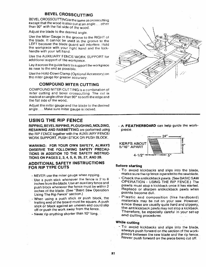
BEVEL CROSSCUTTING
BEVEL CROSSCUTTI NG is the same as crosscuttingexcept that the wood is also cut at an ang{e,, • otherthan 90° with the flat side of the wood.
Adjust the blade to the desired angle.
Use the Miter Gauge in the groove to the RIGHT ofthe blade. _t cannot be used in the groove to theLEFT because the blade guard wilm interfere. Holdthe workpiece with your right hand and the lock-handle with your left hand.
Use the AUXILIARY FENCE/WORK SUPPORT foradditional support of the workpiece_
Lay it across the guide bars to support the workpieceas near to the end as possible.
Use the Hold-Down Clamp (Optional Accessory) onthe miter gauge for greater accuracy.
COMPOUND MITER CUTTmNG
COMPOUND MITER CUTTING is a combination ofmiter cutting and bevel crosscutting. The cut ismade at an angle other than 90° to both the edge andthe flat side of the wood.
Adjust the miter gauge and the blade to the desiredangle... Make sure miter gauge is locked.
USING THE RiP FENCERIPPING, BEVEL RIPPING, PLOUGHING, MOLDING,RESAWING AND RABBETTING are performed usingthe RIP FENCE together with the AUXILIARY FENCE/WORK SUPPORT, PUSH STICK OR PUSH BLOCK.
WARNING: FOR YOUR OWN SAFETY, ALWAYSOBSERVE THE FOLLOWING SAFETY PRECAU-TIONS iN ADDITION TO THE SAFETY INSTRUC-TIONS ON PAGES 2, 3, 4, 5, 6, 26, 27, AND 28.
ADDiTiONAL SAFETY iNSTRUCTiONSFOR RiP TYPE CUTS
- NEVER use the miter gauge when ripping.- Use a push stick whenever the fence is 2 to 6
inches from the blade. Use an auxitiary fence andpush block whenever the fence must be within 2inches of the blade. (See "Basic Saw OperationUsing The Rip Fence" section.)
-When using a push stick or push block thetrailing end of the board must be square. A pushstick or block against an uneven end could slipoff or push the work away from the fence.
- Never rip anything shorter than !0" long.
- A FEATHERBOARD can help guide the work-piece.
I-- 24"
KERFS ABOUT ]_,5/16" APART
4-1/2' 5"
Before starting-To avoid kickbacks and slips into the blade,
make su re the rip fence is parallel to the sawblade.- Check the antikickback pawls. (See BASIC SAW
OPERATION - USING THE RIP FENCE.) Thepawls must stop a kickback once it has started.Replace or sharpen antikickback pawls whenpoints become dull.
-Plastic and composition (ike hardboard)materials may be cut on your saw. However,since these are usually quite hard and slippery,the antikickback pawls may not stop a kickback.Therefore, be especially careful in your set-upand cutting procedures.
While cutting-To avoid kickbacks and slips into the blade.
a!ways push forward on the section of the work-piece between the saw blade and the rip fence.Never push forward on the piece beinq cut off.
31
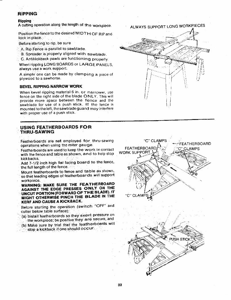
RIPPING
RippingA cutting operation along the length of the workpiece.
Position the fence to the desired WIDTH OF RIP andlock in place.
Before starting to rip, be sure
A_ Rip Fence is parallel to sawblade.B. Spreader is properly aligned with sawbladeC. Antikickback pawls are functioning properly
When ripping LONG BOARDS or LARGE PANEL_always usea work support.
A simple one can be made by clamping a piece olplywood to a sawhorse.
BEVEL RIPPING NARROW WORK
When bevel ripping material 6 in. or narrower, usefence on the right side of the blade ONLY. This willprovide more space between the fence and thesawblade for use of a push stick. If the fence ismounted to the left, the sawblade guard may _nterferewith proper use of a push stick.
ALWAYS SUPPORT LONG WORKPIECES
//
USING FEATHERBOARDS FORTHRU-SAWlNG
Featherboards are not employed for thru-sawingoperations when using the miter gauge.Feat herboards are used to keep the work in contactwith the fence and table as shown, and to heip stopkickbacks.Add 7-1/2 inch high flat facing board to the fence,the full length of the fence.Mount featherboards to fence and table as shown,so that leading edges of featherboards will supportworkpiece.WARNING: MAKE SURE THE FEATHERBOARDAGAINST THE EDGE PRESSES ONLY ON THEUNCUT PORTION (FORWARD OF THE BLADE). ITMIGHT OTHERWISE PINCH THE BLADE IN THEKERF AND CAUSE A KICKBACK.
Before starting the operation (switch "OFF" andcutter below table surface):(a) Install featherboards so they exert pressure on
the workpiece; be positive they are secure, and
(b} Make sure by trial that the featherboards willstop a kickback if one should occur.
"C" CLAMPS
FEATHERBOARDWORK SUPPORT..
"C'" CLAMPS
_FEATHERBOARD
32
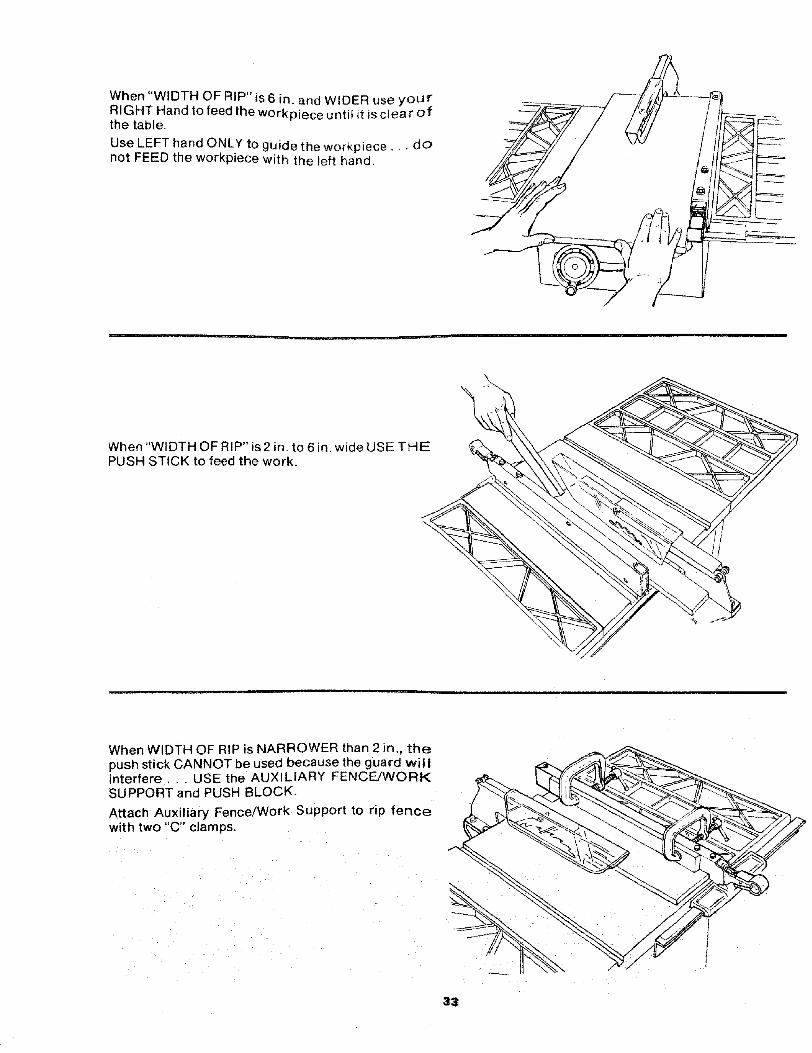
When "WIDTH OF RIP" is6 in, and WIDER use yourRIGHT Hand to feed the workpiece until it is clear ofthe table,
Use LEFT hand ONLY to guide the workpiece.,, donot FEED the workpiece with the left hand.
When "Wl DTH OF RIP" is 2 in. to 6 in, wide USE THEPUSH STICK to feed the work.
When WIDTH OF RIP is NARROWER than 2 in., thepush stick CANNOT be used because the guard wil!interfere, . . USE the AUX LIARY FENCE/WORKSUPPORT and PUSH BLOCK,
Attach Auxiliary Fence/Work Support to rip fencewith two "C" clam ps.
33
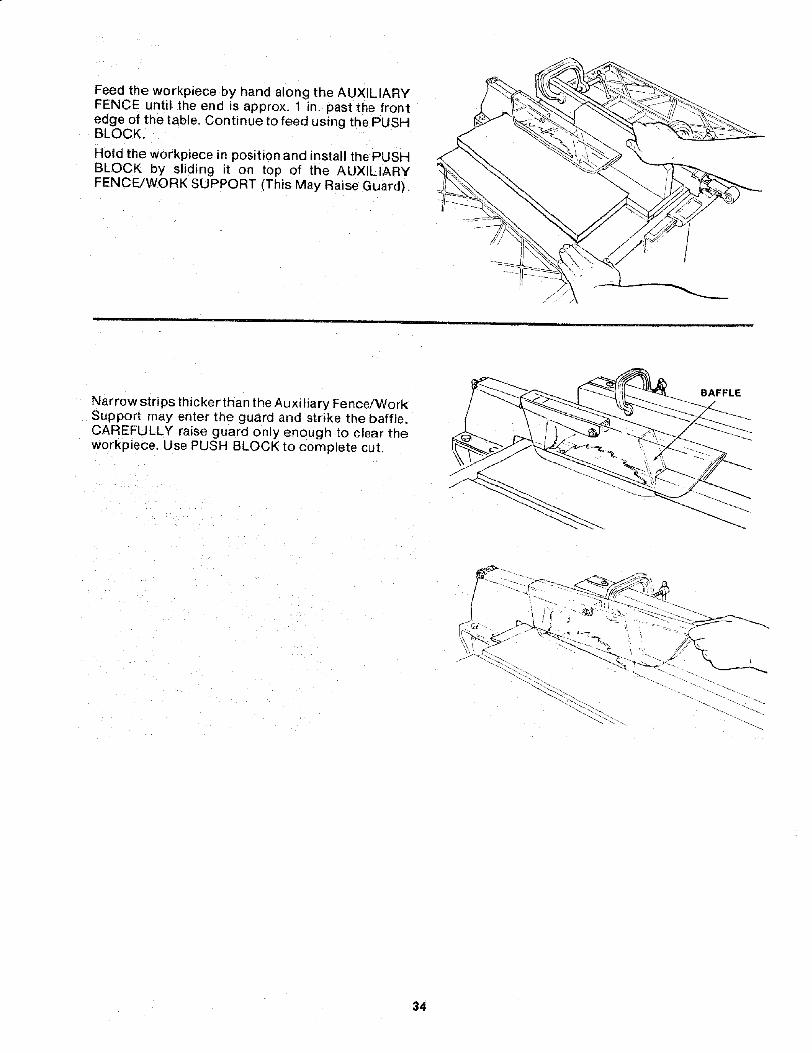
Feed the workpiece by hand along the AUXILIARYFENCE until the end is approx. 1 in. past the frontedge of the table. Continue to feed using the PUSHBLOCK,
Hold the workpiece in position and install the PUSHBLOCK by sliding it on top of the AUXILIARYFENCE/WORK SUPPORT (This May Raise Guard).
Narrow strips thicker than the Auxiliary Fence!WorkSupport may enter the guard and strike the baffle.CAREFULLY raise guard only enough to clear theworkpiece. Use PUSH BLOCK to complete cut.
BAFFLE
34

RE;SAWING
RESAWING is known as ripping a piece of woodthrough its thickness. Do not attempt to resawBOWED or WARPED material. NOTE: To RESAW apiece of wood wider than 3-3/8 inch . . . it will benecessary to remove the blade guard,,, and use theAUXILIARY FENCE/WORK SUPPORT (See "WorkHelpers").
Clamp itto the table so that the workpiece will SLIDEEASILY but not TILT or MOVE SIDEWAYS withoutBINDING between the two fences.
Do not clamp directly to the bottom edge of the tablebecause the "swivel" of the clamp will not gripproperly. Place a small block of wood between thebottom edge of the table and the "C" clamp.
WARNING: FOR YOUR OWN SAFETY,..1. DO NOT "BACK UP" (REVERSE FEED)
SMALL BLOCKOF WOOD
//
2. MAKE FIRST PASS TO A DEPTH SLIGHTLY LES.€THAN ONE-HALF THE WIDTH OF THE BOARDKEEP SAME FACE OF BOARD AGASINT FENCiFOR SECOND PASS AS THE FIRST PASS.
3. INSTALL BLADE GUARD IMMEDIATELY UPOI_COMPLETION OF THE RESAWING OPERATION
CUTTING PANELS
When cutting panels (whenever fence is positionedoutside of table surface), ALWAYS use the AUX-ILIARY PANEL/WORK SUPPORT.
1. Unlock fence and raise rear end.
2. Position AUXILIARY FENCE/WORK SUPPORTas shown and attach it with two "C" clamps.
AUXILIARY PANE
USING FEATHERBOARDS FORNON-THRU SAWING
Featherboards are not employed during non thru-sawing operations when using the miter gauge.Use featherboards for all other non "thru-sawlng"operations (when sawblade guard must beremoved). Featherboards are used to keep the workin contact with the fence and table as shown, and tostop kickbacks.Add 7-1/2 inch high flat facing board to the fence,the full length of the fence.Mount featherboards to fence and table as shown,so that leading edges of featherboards will supportworkoiece until cut is complete, and the workpiece
has been pushed completely past the cutte(sawblade, dado head, molding head, etc.) withpushstick, as n ripping.
Before starting the operation (switch "OFF" antcutter below table surface):
(a) Instalt featherboards so they exert pressure orthe workpiece: be positive they are secure an€
(b) Make sure by trial that the featherboards wilstop a kickback if one should occur.
Replace the sawblade guard as soon as the nonthru-sawing operation is complete.
"C" CLAMPSBOARD
FEATHERBOARD "C'" CLAMPS
WORK SUPPORT
"'C" CLAMPS
35
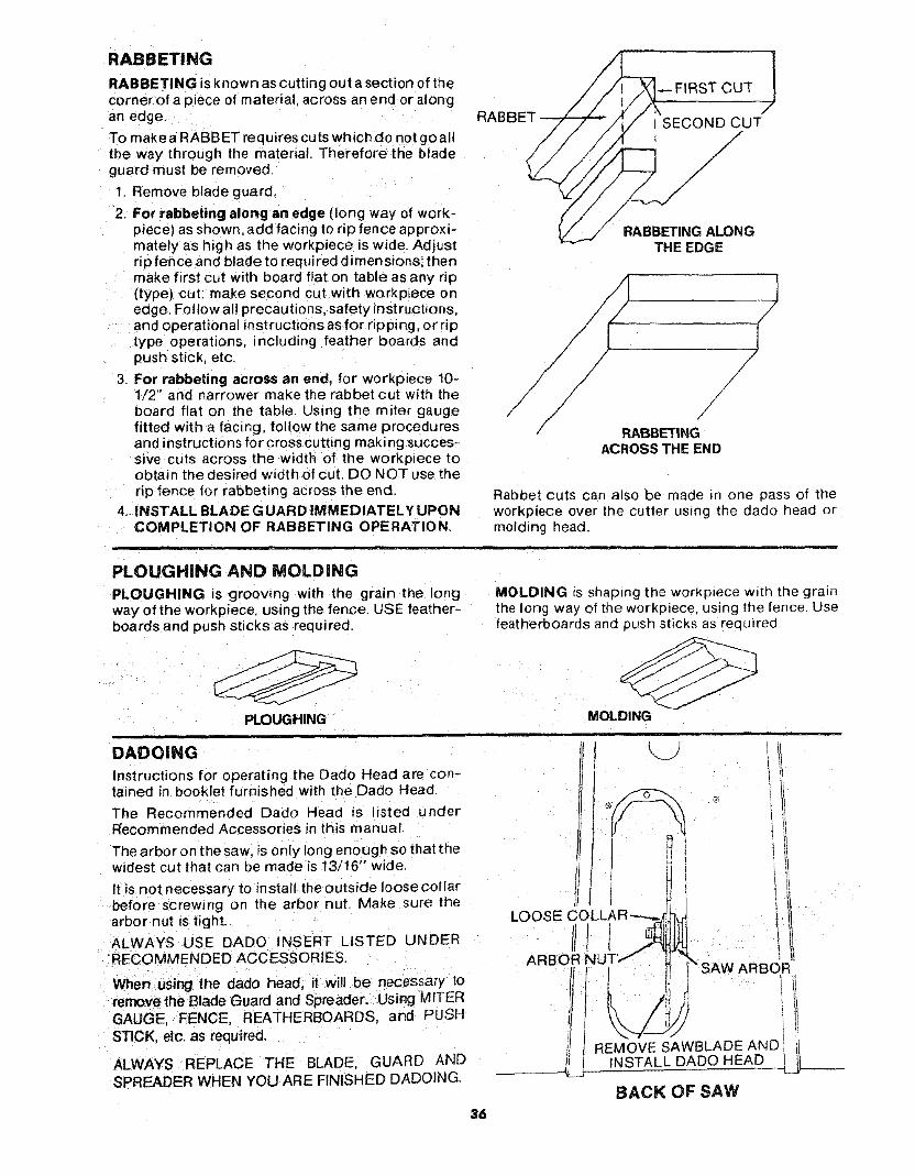
RABBETING
RABBETING is known as cutting out a section of thecorner of a piece of material, across an end or alongan edge
To make a RABBET requires cuts which do not go allthe way through the material. Therefore the bladeguard must be removed
1 Remove blade guard.
2. For rabbeting along an edge (long way of work-piece) as shown, add facing to rip fence approxi-mately as high as the workplece is wide. Adjustrip fence and blade to required dimensions; thenmake first cut with board flat on table as any rip(type) cut: make second cut with workpiece onedge. Follow al! precautions, safety instructions,and operational instructions as for ripping, or riptype operations, including feather boards andpush stick etc.
3. For rabbeting across an end, for workpiece 10-1/2" and narrower make the rabbet cut with theboard flat on the table. Using the miter gaugefitted with a facing, follow the same proceduresand instructions for cross cutting making succes-sive cuts across the width of the workpiece toobtain the desired width of cut. DO NOT use therip fence for rabbeting across the end.
4. iNSTALL BLADE G UARD IMMEDIATELY UPONCOMPLETION OF RABBETING OPERATION,
RA
_FIRST CUT J
J
SECOND CUT/
//
//
//
/
RABBETING ALONGTHE EDGE
/
//
//
/RABBETING
ACROSS THE END
Rabbet cuts can also be made in one pass of theworkpiece over the cutter using the dado head ormolding head.
i
PLOUGHING AND MOLDaNG
PLOUGHING is grooving with the grain the longway of the workpiece using the fence. USE feather-boards and push sticks as req ui red,
PLOUGHING
DADOING
Instructions for operating the Dado Head are con-tained in booklet furnished with the Dado Head.
The Recommended Dado Head is isted underRecommended Accessories in this manual.
The arbor on the saw, is only long enough so that thewidest cut that can be made is 13/16" wide.
It is not necessary to install the outside loose cotlarbefore screwing o_ the arbor nut. Make sure thearbor nut is tight.
ALWAYS USE DADO INSERT LISTED UNDERRECOMMENDED ACCESSORIES.
MOLDING _sshaping the worKplece w_th the grainthe long way of the workpiece, using the fence. Usefeatherboards and push sticks as rec uired
MOLDING,, ,p ,
LOOSE COLLAR'-----_j
1ARBOR NUT"
When using the dado head, it will be necessary toremovelhe Blade Guard and Spreader. Using MITERGAUGE, FENCE, REATHERBOARDS and PUSHSTICK, etc. as required,
ALWAYS REPLACE THE BLADE, GUARD ANDSPREADER WHEN YOU ARE FINISHED DADOING.
_SAW ARBOR
REMOVE SAWBLADEANDINSTALL DADO HEAD
BACK OF SAW
36
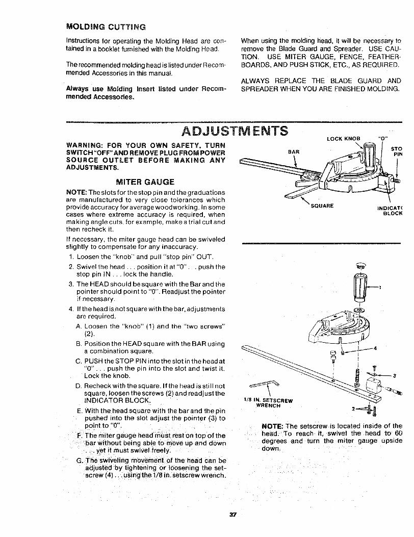
MOLDING CUTTING
Instructionsfor operating the Molding Head are con-tained in a booklet furnished with the Molding Head.
The recommended molding head is listed under Recom-mended Accessories in this manual.
Always use Molding Insert listed under Recom-mended Accessories.
When using the molding head, it wil! be necessary toremove the Blade Guard and Spreader. USE CAU-TION. USE MITER GAUGE, FENCE, FEATHER-BOARDS, AND PUSH STICK, ETC., AS REQUIRED.
ALWAYS REPLACE THE BLADE GUARD ANDSPREADER WHEN YOU ARE FINISHED MOLDING.
ADJUSTMENTSWARNING: FOR YOUR OWN SAFETY, TURNSWITCH "OFF" AND REMOVE PLUG FROM POWERSOURCE OUTLET BEFORE MAKING ANYADJUSTMENTS.
BAR
i
LOCK KNOB\
"0"
STOPIN
MITER GAUGE
NOTE: The slots for the stop pin and the graduationsare manufactured to very close tolerances whichprovide accuracy for average woodworking. In somecases where extreme accuracy is required, whenmaking angle cuts, for example, make a trial cut andthen recheck it.
f necessary, the miter gauge head can be swiveledslightly to compensate for any inaccuracy.
1. Loosen the "knob" and pull "stop ;)in" OUT.
2. Swivel the head., position it at "0"... push thestop pin IN... lock the handle.
3. The HEAD should be square with the Bar and thepointer should point to "0". Readjust the pointerif necessary.
4. If the head is not square with the bar. adjustmentsare required.
A Loosen the "knob" (1) and the "two screws"(2).
B Position the HEAD square with the BAR usinga combination square.
C PUSH the STOP PIN into the slot in the head at"0" .. push the pin into the slot and twist it.Lock the knob.
D. Recheck with the square. If the head is still notsquare, loosen thescrews (2) and readjust theINDICATOR BLOCK.
E. With the head square with the bar and the pmpushed into the slot adjust the pointer (3) topoint to "0".
F. The miter gauge head must rest on top of thebar without being able to move up and down•.. yet it must swivel freely
G. The swiveling movement of the head can beadjusted by tightening or loosening the set-screw (4)... using the 1/8 in. setscrew wrench.
SQUARE IND|CAT(BLOCK
I
t
V
1/8 IN. SETSCREw
WRENCH 2_
NOTE: The setscrew is located inside of thehead. To reach it, swivel the head to 60degrees and turn the miter gauge upsidedown.
37

HEELING ADJUSTMENT orPARALLELISM OF SAWBLADE TO MITER
GAUGE GROOVE
While cutting, the material must move in a straightline PARALLEL to the SAWBLADE... therefore boththe miter gauge GROOVE and the RIP FENCE mustbe PARALLEL to the SAWBLADE,
If the sawblade IS NOT parallel to the miter gaugegroove, the blade will bind at one end of the cut.(This is known as "HEELING"),
To check for parallelism:
WARNING -- FOR YOUR OWN SAFETY, TURNSWITCH "OFF" AND REM OVE PLUG FROM POWERSOURCE OUTLET.
1. Raise blade all the way up., • raise blade guard.
2. Mark an "'x" on one of the teeth which is SET(bent) to the LEFT
3. Place the head of a combination square in theGROOVE ,,. adjust blade of square so that it justtouches the tip of the MARKED tooth_
4, Move square to REAR. rotate blade to see ifMARKED tooth again touches blade of square.
5, If tooth touches square at FRONT and REAR..sawblade is PARALLEL to MITER GAUGEGROOVE.
6. If tooth does not touch the same amount .. themechanism underneath must be adjusted tomake the blade PARALLEL to GROOVE.
A. Rear trunnion must be moved TOWARD thecombination square if there is a space betweenmarked tooth and end of square in step 4
13.Rear trunnion must be moved AWAY from thesquare if marked tooth pushes square out ofposition in the groove,
FRONT TRUNNION REAR TRUNNION
7, Loosen all three screwsthat hold the rear trun nionand all three screws that hold the front trunnion,
NOTE: All six screws can be reached throughback of saw. Use a 9/16 in, wrench. To reachleft-hand front trunnion screw, tilt blade to 45 ° .After loosening screws reposition blade at 90 ° .
REAR-TRUNNIONSCREWS
(BEHIND HERE) (BEHIND HERE)i \FRONT-TRUNNION SCREWS
38
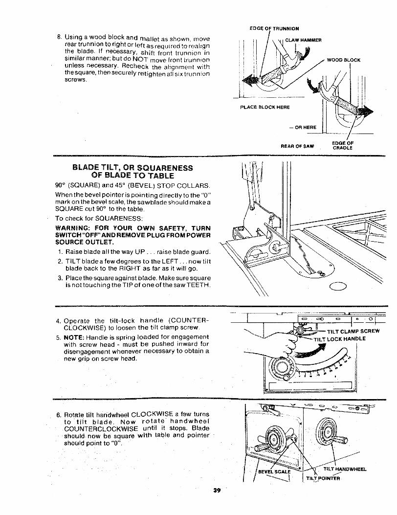
8. Using a wood block and mallet as showm moverear trunnion to right or left as required to realignthe blade. If necessary, shift front trunnion insimilar manner; but do NOT move front trunnionunless necessary. Recheck the alignment withthe square, then securely retighten a!l six trunnionscrews.
EDGE OF TRUNNION
CLAW HAMMER
WOOD BLOCK
PLACE BLOCK HERE_ OR HERE
),
EDGE OFREAR OF SAW CRADLE
BLADE TILT, OR SQUARENESSOF BLADE TO TABLE
90° (SQUARE) and 45° (BEVEL) STOP COLLARS.
When the bevel pointer is pointing directly to the "0"mark on the bevel scale, the sawblade should makeaSQUARE cut 90° to the table.
To check for SQUARENESS:
WARNING: FOR YOUR OWN SAFETY, TURNSWITCH "OFF' AND REMOVE PLUG FROM POWERSOURCE OUTLET.
1. Raise blade all the way UP... raise blade guard.
2. TILT blade a few degrees to the LEFT... now dltblade back to the RIGHT as far as it will go.
3. Place the square against blade. Make sure squareis not touching the TIP of one of the saw TEETH.
4. Operate the tilt-lock handle (COUNTER-CLOCKWISE) to loosen the tilt clamp screw.
5. NOTE: Handle is spring loaded for engagementwith screw head - must be pushed inward fordisengagement whenever necessary to obtain anew grip on screw head.
"ILT LOCK HANDLE
6. Rotate tilt handwheel CLOCKWISE a few turnsto tilt blade, Now rotate handwheelCOUNTERCLOCKWISE until it stops. Bladeshould now be square with table and pointershould point to "0".
39
BEVEL SCALETILT HANDWHEEL
TILLPOINTER
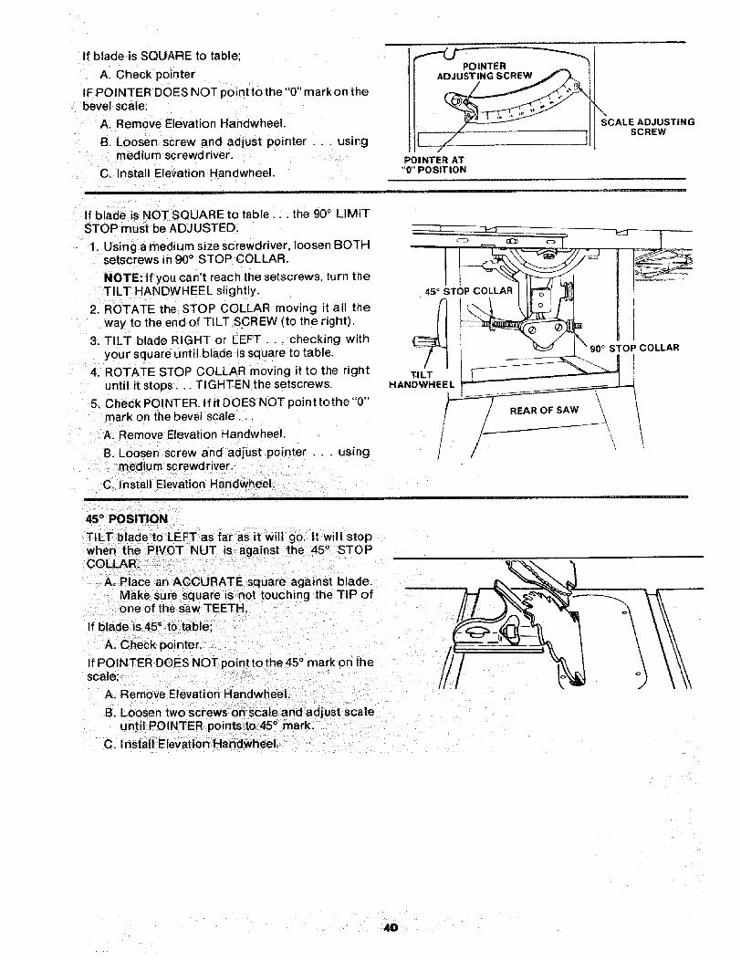
If blade is SQUARE to table;
A. Check pointer
IF POINTER DOES NOT pointto the"0" mark on thebevel scale:
A. Remove Elevation Handwheel.
B. Loosen screw and adjust pointer . . . usingmedium screwdriver.
C. Install Elevation Handwheel.
POINTER
POINTER AT"O"POSITION
SCALE ADJUSTINGSCREW
If blade is NOT SQUARE tc table.., the 900 LIMITSTOP must be ADJUSTED.
1. Using amedium sizescrewdriver, loosen BOTHsetscrews in 90° STOP COLLAR.
NOTE: If you can't reach the setscrews, turn theTILT HANDWHEEL slightly.
2. ROTATE the STOP COLLAR moving it all theway to the end of TILT SCREW (to the right).
3. TILT blade RIGHT or LEFT... checking withyour square until blade is square to table+
4. ROTATE STOP COLLAR moving it to the rightuntil it stops,, _TIGHTEN the setscrews.
5. Check POINTER. If it DOES NOT point tothe "0"mark on the bevel scale.
A. Remove Elevation Handwheel.
B. Loosen screw and adjust pointer . . . usingmedium screwdriver.
C. Install Elevation HandwheeL
45 ° STOP COLLAR
4TI LT
HANDWHEEL
STOP COLLAR
45° POSITION
TILT blade to LEFTas farasit will go, It will stopwhen the PIVOT NUT is against the 45 ° STOPCOLLAR.
A. Place an ACCURATE square against blade.Make sure square is not touching the TiP ofone of the saw TEETH.
If bladeis45 ° to table;
A. Check pointer.
If POINTER DOES NOT point tothe45 ° mark on thescale;
A. Remove Elevation HandwheeL
B. Loosen two screws on scale and adjust scaleunt I PC NTER points to 45° mark.
C. install Elevation Handwheel.
4O

IfbladeisNOT45° STOPCOLLARandSCALEmustbeADJUSTED.1.RemoveElevationHandwheel.2. Usingasmallsizescrewdriver,reachthrucurved
slot in front trim paneland loosenBOTHset-screwsin45° STOP COLLAR.
NOTE: If you can't reach the setscrews, turn theTILT HANDWHEEL slightly.
3. ROTATE the STOP COLLAR moving it IN orOUT and TILT blade RIGHT or LEFT . . .checking with your square until blade is 45° totable.
4. TIGHTEN the setscrews.
NOTE: If you can't reach the setscrews, turnTILT HANDWHEEL slightly.
5. Loosen two screws on scale and adjust scaleuntil POINTER points to 45° mark.
6. Install Elevation Handwheel.
TiLT MECHANISM
The handwheel should turn freely without binding.The turning action can be adjusted by tightening orloosening the screws in the bearing retainer.
NOTE: Tilt Handwheel must be removed to adjust.When adjusting the screws _nthe bearing retainer,hold the nut inside using a 3/8 in. wrench.
TILT HANDWHEEL
JJ/
ADJUST THESETWO SCREWS
MAINTENANCEWARNING: FOR YOUR OWN SAFETY, TURNSWITCH "OFF" AND REMOVE PLUG FROM POWERSOURCE OUTLET BEFORE MAINTAINING ORLUBRICATING YOUR SAW,
Do not allow sawdust to accumulate inside the saw.
Frequently blow out any dust that may accumulateinside the saw cabinet and the motor.
Frequently clean your cutting tools with CraftsmanGum and Pitch Remover.
A coat of automobile-type wax applied to the tablewill help to keep the surface clean and allow work-pieces to slide more freely.
If the power cord is worn or cut, or damaged in anyway, have it replaced immediately.
Make sure the teeth of the ANTIKICKBACK pawlsare always sharp. To sharpen:
1 Remove blade guard.
2. Rotate paw l toward rear of spreader so that tee1are above top of spreader.
3. Hold spreade rwith left hand and place pawl ovcorner of workbench.
4. Using a smatl round file (Smooth Cut) sharp_the teeth.
4t
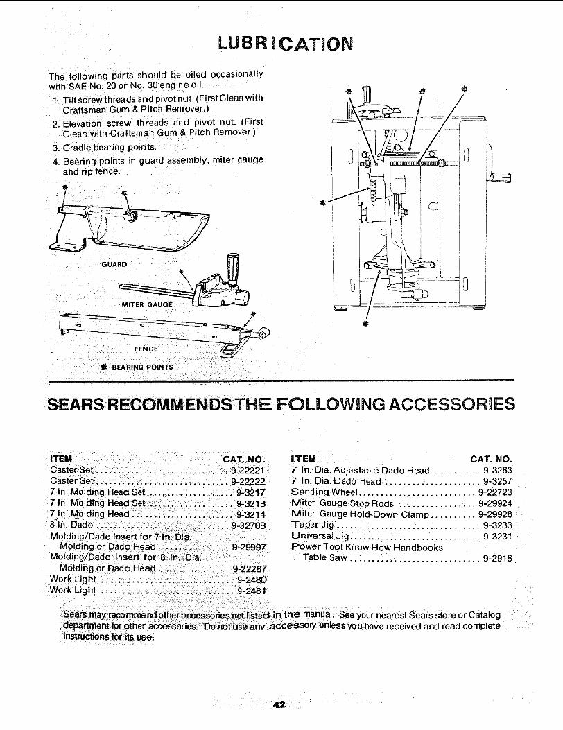
LUBRiCATiON
The following parts should be oiled occasionallywith SAE No. 20 or No. 30 engine oil.
1. Tilt screw th reads and pivot nut. (First Clean withCraftsman Gum & Pitch Remover.)
2. Elevation screw threads and pivot nut. (FirstClean with Craftsman Gum & Pitch Remover.)
3. Cradle bearing points.
4. Bearing points n guard assembly, miter gaugeand rip fence.
0t
t BEARING POINTS
SEARS RECOMMENDS THE FOLLOWING ACCESSORIES
CAT. NO.7" In: Dia. Adjustable Dado Head ........... 9.3263
.._. :,_:,, ,:::;, 9_22222 7' In: Dia. Dado Head ....................... 9-325771nl U0iding Head set i i ,;: ii :, 9:3217 sanding Wheel.. i.. :_ ......... i ......... 9-22723
7 In: Molding i 9-32i8 Miter--Gauge stop Rods ................. 9-299247 In! Molding Head _: ::: :i _ 9:3214 Miter'Gauge Hoid-Down Clamp ...... :.. 9-299288'In. Dado ;i ::. 9_32708 Taper,Jig .... ,.._.. ...................... 9'3233Mold}ngiDad0 Universal Jig. :. i: _.:::., ................. 9=3231
Molding or Dado Power Tool KnoW How HandbooksMod ngiDado TabieSaW.. :.:i:!:_ ..... ..... 9-2918
Mbidi_g Or 0ad0 i::i i 9_22287WorkUght _i:,i., :! 9_2480
nearest Sears store or CatalogI read complete

TROUBLE SHOOTING
WARNING: FOR YOUR OWN SAFETy, TURN SWITCH "OFF" AND ALWAYS REMOVE PLUG FROM POWER SOURCEOUTLET BE FORE TROUBLESHOOTING.
TROUBLE SHOOTING "- GENERAL
TROUBLE
Excessive vibration.
Cannot make square
Cut when crosscutting,
Cut binds, burns or
stalls motor when
ripping.
PROBABLE CAUSE
1. Blade out of balanceL,____
1. Miter gauge not adjusted
properly,
1. Dull blade with improper
tooth set.
2. Blade is Heeling.
3. Warped board.
REMEDY
1, Discard Blade and use a different blade.
1. See "Adjustments" section "Miter Gauge."
4. Rip fence not parallel
to blade,
5. Spreader out of
alignment
1. Stop collars not properly
adjusted.
1. Sawdust on threads of ti_t
screw or elevating screw.
2. Bearing retainers
to tight,
1. Sharpen or replace blade.
2. See "Adjustments" section, "Heeling Adjustment...'"
3, Make sure concave or hollow side is facing
"down," feed slowly.
4. See "Assembly" section, "Aligning Rip Fence"
5. See "Assembly" section, "Installing
Blade Guard."
Cut not true at B0 ° 1. See "Adjustments" section, "'Blade Tilt, or
or 45 ° positions. "Squareness of Blade to Table."Jn " " _' " nTilt and elevating 1. See Maintenance and Lubrication sect o .
handwhee| turn hard.2. See "Maintenance" section
"Tilt and Elevation Mechanism."
TROUBLE SHOOTmNG -- MOTOR
NOTE: Motors used on wood-working tools are particularlysusceptible to the accumulation of sawdust and wood chipsand should be blown out or "vacuumed" frequently toprevent interference with normal motor ventilation.
TROUBLE PROBABLE CAUSE
Excessive noise. 1. Motor.
Motor fails to develop
full power. (Power
output of motor decreases
rapidly with decrease in
voltage at motor terminals.
For example, a reduction
of !0% in voltage causes
a reduction of 19% in
maximum power output
of which the motor is
capable, while a reduction
of 20% in voltage causes
a reduction of 36% in
maximum power output.)
1. Circuit overloaded with
lights, appliances and
other motors.
2. Undersize wires or circuit
too long.
3. General overloading of
power company
facilities, (In some
sections of the
country, demand for
electrical power may
exceed the capacity
of existing generating
and distribution systems, }
4. Incorrect fuses or circuit
REMEDY
1. Have motor checked by qualified service
technician. Repair service is available at
your nearest Sears store.
1, Do not use other appliances or motors on
same circuit when using the saw.
2. Increase wire sizes, or reduce length of wiring.
See "Motor Specification and Electrical
Requirements" section.
3. Request a voltage check from the power company.
breakers in power line.
4. Install correct fuses or circuit breakers.

TROUBLE SHOOTING MOTOR (Continued)
I PROBABLE CAUSETROUBLE
to full speed,
Motor overheats,
REMEDY
Starting switch in
motor will not
operate.
1. Low voltage will not j
2. Windings burned out
' or open.
3. Starting relay not
operating.
1. Motor overloaded,
2. Improper cooling. (Air
circulation restricted
through motor due to
sawdust, accumulating
• inside of saw).
1. Burned switch contacts
(due to extended
hold-in periods caused
by low line voltage, etc.}
2. Shorted capacitor
(when equipped)
1. Request voltage check from the power company.
2. Have motor repaired or replaced.
3. Have relay replaced.
I. Feed work slower into blade.
2. Clean out sawdust to provide normal air
circulation through motor.
See "Maintenance and Lubrication" section.
1. Have switch replaced and request a voltage check
from the power company.
2. Test capacitor and replace if defective.
3. Loose or broken " 3. Have wiring checked and repaired.
connections. II. Starting switch' not 1'. Have switch replaced.
t{resulting in blown operating.o I o r I 1fuses or tripped 2. Voltage to ow t pe m't I 2. Request voltage check from the power company.
circuit breakers), motor to reach operating I
, speed.
! 3. Fuses or circuit breakers 3. Install proper size fuses or circuit breakers.
do not have sufficientt
capac=ty
I. Motor overloaded. I. Feed work slower into blade.
2. Fuses or circuit breakers i 2. Install proper size fuses or circuit breakers.
breakers, do not have sufficient
I capac=ty.3. Starting switch not
operating (motor does
not reach speed).
3. Have switch replaced,
44
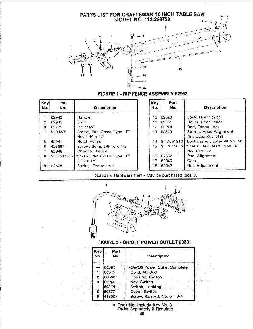
PARTS LiST FOR CRAFTSMAN 10 INCH TABLE SAW 9 10
MODELNO.113.298720 , /_!
I#,_ /
; &_]s
FIGURE 1 - RIP FENCE ASSEMBLY 62952
KeyNo.
1
23
4
5678
Part
No.
62942
6294562775
9404336
6294142356762946STD600805
62528
Description
Handle
ShoeIndicator
Screw, Pan Cross Type "T"No. 4-40 x 1/4
Head. FenceScrew, Sems 3/8-16 x 1/2
Channel, Fence
*Screw. Pan Cross Type "T"8-32 x 1/2
Spring, Fence Lock
Key PartNo. No.
10 6252911 62531
12 62944
13 62533
14 STD551210
15 STD611005
16 6253217 62940
18 62943
Description
Lock, Rear Fence
Roller, Rear FenceRod. Fence Lock
Spring, Head Alignment(Includes Key #18)
*Lockwasher, External No. 10
*Screw, Hex Head Type "A"No. 10 x 1/2
Pad, AlignmentCam
Nut, Adjustment
* Standard Hardware Item - May be purchased locally.
5
FIGURE 2 - ON/OFF POWER OUTLET 60381
DescriptionK iey I PaNNo. No.
-- 60381
1 603752 60380
3 60256
4 603745 60377
6 i448007
oOn/Off Power Outlet CompleteCord, Molded
Housing. SwitchKey, SwitchSwitch, Locking
Cover, SwitchScrew, Pan Hd. No. 6 x 3/4
• Does Not Include Key No. 3Order Separately if Required.
45

PARTS LIST FOR CRAFTSMAN 10 INCH TABLE SAWMODEL NO. 113.298720
12 13 16
1
32 33
31
Figure 3
//
i j3O
27 28
29 28
! !
_///_ /524 23

PARTS LiST FOR CRAFTSMAN 10 iNCH TABLE SAWMODEL NO. 113.298720
Always order by Part Number - not by Key Number.
FIGURE 3 PARTS LIST
Key I PartNo. I No.
1 625792 ISTD5225063 ISTD551225
4 ISTD5410255 ISTD5231106 16254!7 'STD5512318 ISTD541031
9 J6031310 !627O3
11 16271812 ISTD50110213 113364514 162584
15 16249316 16295217 16271018 162709
19 16253920 16038121 ISTD52311722 16270423 ISTD511107
Description
Guard Assembly (See Fig. 6)*Screw. Hex Hd. 1/4-20 x 5/8
*Lockwasher, External 1/4*Nut. Hex 1/4-20*Screw. Hex 5/16-18 x 1Bar Fence Rear
*Lockwasher, External 5/16*Nut, Hex 5/16-18
Nut, Self-threadingInsert Assembly,
(Includes Key No. 11 & 12)Clip, Retaining
*Screw. Locking Set 10-32 x 3/16Screw. Flat Hd. 10-32 x 1
Rod, SeparationInsert, Exact-l-Cut
Fence Assembly, Rip (See Fig. 1)Tape, FenceBar Assembly, Fence Guide
ncludes Key No. 17)Spacer. Fence Guide Bar
Switch Assembly Box (See Fig. 2)*Screw, Hex 5/16-18 x 1-3/4Gauge Assembly, Miter (See Fig. 5)
*Screw. Pan Hd. t0-32 x 3/4
Key PartNo. No, Description
24 STD55121025 6268926 STD51110327 6270128 STD61080529 6270230 62700
31 6025232 6025533 STD60110534 6025335 6025436 45489637 STD55123738 7116539 STD5414!140 6261841 STD52250742 STD551031
62750
62751SP5116
*Lockwasher, External No. 10Handwheet Assembly
*Screw, Pan Hd. 10-32 x 3/8
Panel, Front*Screw, Pan Hd. Ty "AB" No. 8 x 1/2Scale, Adjustable BevelBase
Guard, Belt
Clip, "S"*Screw, Pan Hd. Ty "T" 10-32 x t/2Support, Belt GuardBracket, Support
*Screw, Hex Hal. 3/8-!6 x 1/2*Lockwasher, External 3/8Tie, WireNut, Lock 10-32
+Motor*Screw, Hex Hd. 5/16-18 x 3/4*Washer, 21/64 x 5/8 x 1/16
Bag of Loose Parts (Not Illustrated)(Includes Bag 62751 )
Bag of Loose Parts (Not Illustrated)Owners Manual (Not Illustrated)
* Standard Hardware Item -. May Be Purchased Locally.
NOTE: Shipping and handling charges for standard hardware items(identified by *) such as nuts, screws, washers, etc., makebuying these items by mail uneconomical. To avoid shippingand handling charges, you may obtain most of these locally.
+ Stock Item - May be secured through the hardware department ofmost Sears Retail Stores or Catalog Order Houses.

PARTS LIST FOR CRAFTSMAN 10 INCH TABLE SAWMODEL NO. 113.298720
44
1213
62
14/
59 56
58
43
31 41 40
f//
16
39
[
i
18 19 20
25
\22
_. 2323
29 30
38 37 36 35 34 34
33 32
21
Figure 4

PARTS LIST FOR CRAFTSMAN 10 INCH TABLE SAWMODEL NO. 113,298720
FIGURE 4 PARTS LIST
Key INo. I
5 I
6 I
8 I
10 t
11 I
12 I
13 t
14 !
15 I16 I
17 I
18 I19 I
20 I
21 I
22 I
23 I
24 t
26 I
26 I
27 I
28 I29 I
30 I31 I
32 I
33 I
PartNo.
62587
60204
STD 571812
STD 523106
STD 523110
STD 551231
62292
STD 541031
STD 532507
60206
60205
STD 551037
6301162295
3042662696
6017562498
6362
35406243762698
37900
STD 523710STD 551237
37899
63054
3782818
37829
STD 581062
3783860178
Description
Support, Spreader
Screw, Thumb 5/16-18 x 1
*Pin, Roll 3/16 x 1-1/4
*Screw, Hex Hd. 5/16-18 x 5/8
*Screw, Hex Hd. 5/16-18 x 1
* Lockwasher, External 5/16
Support, Guard
*Nut, Hex 5/!6-18
*Bolt, Carriage 5/16-18 x 3/4
*Screw, Hex Ind. Wash. Hd.1/4-20 x 1-I/2
Spring
*Washer, 380 x 47/64 x 3/32
Washer, Knob Clamp
Spacer
Table, Trunnion
Table, 10 In. Saw
+Blade, Saw 10 In.
Collar; Blade
Nut, Arbor
Wrench, Arbor
Retainer, Bearing
Screw, Tilt
Collar, Stop
*Screw, Hex Hd. 3/8-16 x 1
*Lockwasher, External 3/8
Nut, Tilt
Ring, Retaining 3/4
Spring, Clamp ScrewHandle, Clamp Screw
Screw, Clamp
*Ring, Retaining 5/8
Washer .629 x 7/8 x 1/64
Washer, Spr!ng
Standard Hardware Item - May Be Purchased Locally.
KeyNo.
34
35
3637
38
39
40
4142
43
44
45
46
47
49
5O51
52
53
5455
56
5758
59
6061
62
63
6465
PartNo,
STD 302111
62697
62699STD 601103
STD 551210
62489
30509
30767
623126527
STD 328022
STD 304410
30419
STD 600803
3508
37158
3509
30420
STD 580025
6532
37825
37824
37823
STD 581037
37836
37887
37837
30628
6423
STD 551025
62585
Description
*O-Ring
Screw, Lift
Pointer
*Screw, Pan Hd. Ty "T" 10-32 x 3/8
* Lockwasher, External No. !0
Cradle (Includes Key No's. 42 and 43)
Washer, End Play (.005 Thick)
Washer, End Play (.010 Thick)
Link
Ring, Retaining 3/4
*Pulley, 5/8 Bore (Includes Set Screw)
*Belt, V 1/2 x 41
Housing, Arbor Assembly (Includes Key No's.44, 47, 49, 50, 51,52, 53, 54)
*Screw, Pan Hd. Ty "T" 8-32 x 3/8
Retainer, Arbor Bearing
Ring, Retaining 5/8
Bearing. Saw Arbor
Housing, Arbor
* Key, Woodruff
Arbor (Includes Key No's. 31,50, 53)
Support, Motor Base
Base, Motor
Pin, Hinge
Ring, Retaining 3/8
Wrench, Hex L 3/32
Wrench, Hex L 1/8
Wrench, Hex L 5/32
Screw, Pivot Arm
Washer, Spring
*Washer, 17/64 x 47/64 x 1/16
Rod, Spreader
+ Stock Item -- May be secured through the Hardware Departmentnf mnst S_rs Rp,tail Storp.s or CataloQ Order Houses.

PARTS LIST FOR CRAFTSMAN 10 INCH TABLE SAWMODEL NO. 113.298720
FIGURE 5 - 62704 MITER GAUGE ASSEMBLY
Key Part
No. No. Description
-- 627041 1626932 62692
I 3
4567
8i9
10
11 STD54123112 5222513 62383
14 60288
STD 55103137893STD 51080313537895378969417295
62230
+Gauge Assembly, MiterPlug, Button
Knob, Miter Gauge(Includes Key No. t)
*Washer, Plain, 21/64 × 1 x 1/16Gauge, Miter
*Screw, Pan Hd. 8-32 x 5/15Indicator
Block, Miter Gauge IndicatorPin, Miter Gauge StopScrew, Pan lid.,
w/Lockwasher, 8-32 x 5/8
Rod Assembly, Miter Gauge,Consisting of Items 11, 12, t3
*Nut, Hex., 5/16-18Stud, ClampStud, PivotScrew, LoCking Set 1/4-20 x 3/8
1
12
11 ! 6
_8 10 9
5 I
FIGURE 6 - 62579 GUARD ASSEMBLY
KeyNo. Description
123456789
101112
PartNo.
62579602976239162395623896239OSTD 55102562520628796258062410STD 57181062519
Guard Assembly, SawNut, PushPin I/4 x 1-I/2'"
Support, GuardGuard, SawPin, 1/4 x 1-3/4"
*Washer, 17/64 x 5/8 x 1t16 °'Spacer, PawlPawl
Spreader, Assembly BladePin, 1/4 x 1"
*Pin, Roll, 3/16 x 15/16"
Spring, Pawl
" Stendard Hardware Item - May Be Purchased Locally.
+ Stock Item - May be secured through the Hardware Departmentof most Sears Retail Stores or Catalog Order Houses.
5O
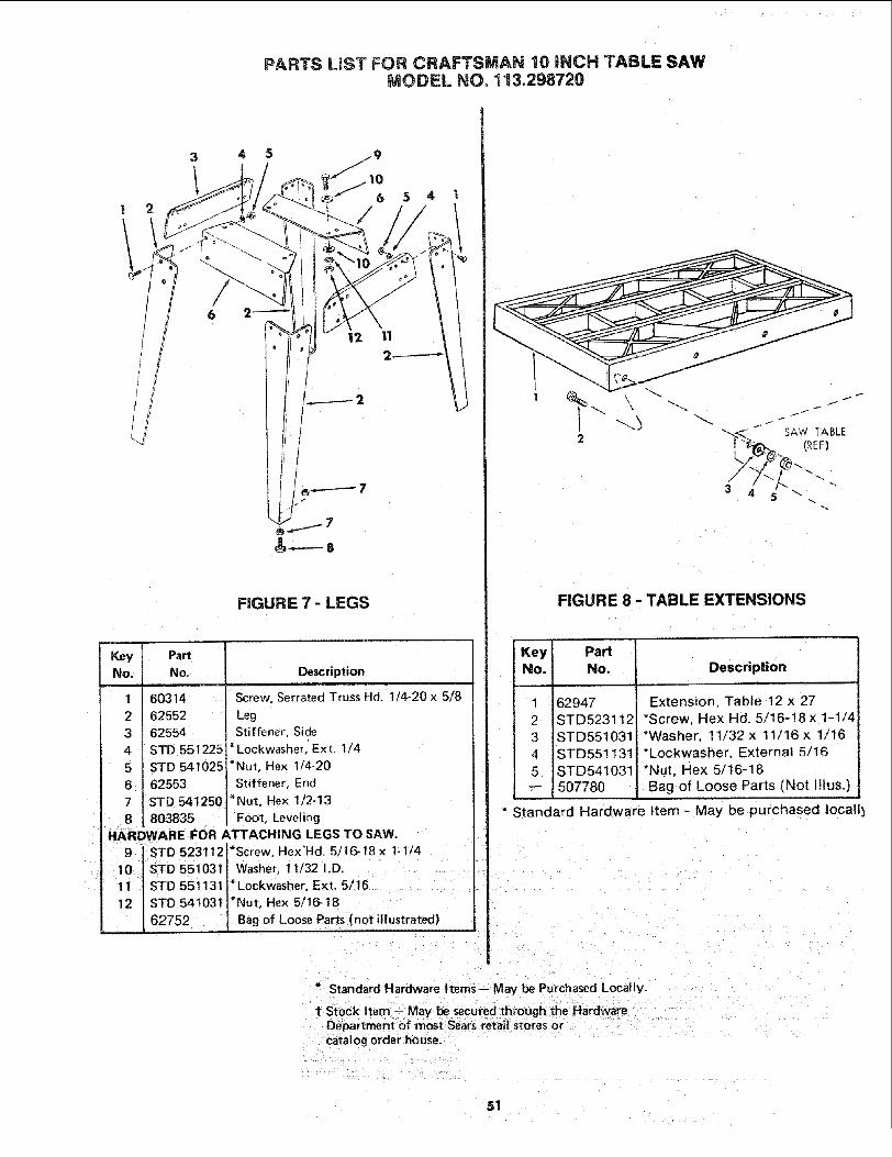
PARTS LiST FOR CRAFTSMAN 10 iNCH TABLE SAWMODEL NO. 113.298720
5 4
I/
FIGURE 7 - LEGS
Key PartNo. No.
1 603142 62552
3 62554
4 STD 551225'
5 STD 541025
6 62553
7 STD 5412508 803835
Description
Screw, Serrated Truss Hd. 1/4-20 x 5/8
Leg
Stiffener, Side
*Lockwasher,' Ext. 1/4
*Nut, Hex 1/4-20
Stiffener, End
*Nut, Hex 1/2-13
Foot, Leveling
HARDWARE FOR ATTACHING LEGS TO SAW.9 STD 523112 *Screw, Hex'Hd. 5/16-18 x 1-1/4
10 " STD 551031 Washer, 11/32 I.D.11 STD 551131 *Lockwasher, Ext. 5/16
12 STD 541031 *Nut, Hex 5/16-18
62752 Bag of Loose Parts (not illustrated)
2
\_3
f
FIGURE 8 - TABLE EXTENSIONS
Key! PartNo. No. Description
1 62947
2 STD523112i
3 STD551031
4 STD5511315 STD541031
Extension, Table 12 x 27
*Screw, Hex Hd. 5/16-18x 1-1/4*Washer, 11/32 x 11/16 x 1/16
*Lockwasher, External 5/16
*Nut, Hex 5/16-18
-- 507780 , Bag of Loose Parts (Not Illus.)
" Standard Hardware Item - May be purchased Iocall_
Standard Hardware Items-- May be Purchased Locally.
t Stock Item - May be secured through the HardwareDepartment of most Sears retail stores orcatalog order house.
51

SERVICE
MODEL NO.113.298720
HOW TO ORDER
REPAIR PARTS
10 iNCH TABLE SAW
Now that you have purchased your 10-inch table saw should aneed ever exist for repair parts or service, simply contact anySears Service Center and most Sears, Roebuck and Co. stores.Be sure to provide all pertinent facts when you call or visit.
The model number of your 10-inch table saw will be found on aplate attached to your saw, at the left-hand side of the base.
WHEN ORDERING REPAIR PARTS, ALWAYS GIVE THEFOLLOWING INFORMATION:
PART NUMBER PART DESCRIPTION
MODEL NUMBER113.298720
NAME OF ITEM10-INCH TABLE SAW
All parts listed may be ordered from any Sears Service Centerand most Sears stores. If the parts you need are not stockedlocally, your order will be electronically transmitted to a SearsRepair Parts Distribution Center for handling.
=
Sold by SEARS, ROEBUCK AND CO., Chicago, IL. 6;0684 U.S.A.Part No. SP5116 Form No. SP51t 6-4 Printedin U.S.A_2/gO