Embed Size (px)
Citation preview

Manual BoardMaster 4.0
English, Version 1.0
LPKF Laser & Electronics AGOsteriede 7D-30827 Garbsen
Telefon : ++ 49 - 51 31 - 70 95 - 0 Telefax : ++ 49 - 51 31 - 70 95 - 90eMail : [email protected] : http: //www.lpkf.de

Copyright (c) 2001 LPKF AGPrinted in Germany. LPKF reserves the right to change specifications and other product information without notice. Systems and products offered by LPKF and its subsidiaries are covered by issued and pending German and foreign patents. Products mentioned are for identification purposes only and may be trademarks or registered trademarks of their respective companies. LPKF logo and ProtoMat are registered trademarks of LPKF Laser & Electronics AGAll rights reserved.
2 BoardMaster 4.0

About this manual This manual
It is an introduction into the operation of BoardMaster 4.0 for Windows. LPKF BoardMaster is a program for the automatic control of HP-GL compatible LPKF circuit board plotters. LPKF BoardMaster 4.0 is capable of importing production data generated by LPKF CircuitCAM 4.0 in LMD format and production data generated by other programs in HP-GL format, of displaying this data graphically on the screen and processing it together with process and job information. The circuit board plotter is fully controlled through BoardMaster. The WYSIWYG (What You See Is What You Get) representation of the data to be processed, the manual control of the circuit board plotter through the Windows interface and the incorporated tool library with all the requisite information guarantees largely automatic prototype production. This manual will guide you from the LMD/HP-GL circuit board data created by CircuitCAM or other programs, through job preparation, to the production of the circuit board prototypes with the circuit board plotter. You will be guided step by step through the program; at critical points in the program we will point out possible sources of errors that might arise because of the structure of the various data sources. In this way, we hope to allow you to identify errors correctly from the outset and to avoid them by defining the important parameters correctly.
BoardMaster 4.0 3
Using this Manual
This tutorial does not cover the basic operation of the Windows interface. Please first refer to your Windows documentation if you are not familiar with the techniques of handling Windows objects.
I. Orientationthis manual is divided into the following chapters::
1. Safety notes2. Installation3. Introduction4. Description of the Menu bar 5. Description of the Function bar6. Specific functions7. Step by Step
II. Conventions used in this manualBold text is used to emphasise important information.
Illustrations are numbered by a system indicating the chapter number and the illustration number.Example: Figure 5-11: illustration 11 in Chapter 5
› Prompts for actions are identified with an arrow.
Italic text is used to inicate the reactions consequent on an action.
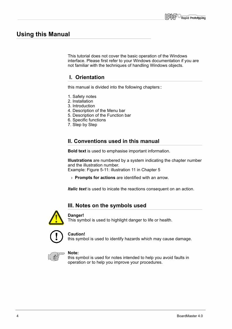
III. Notes on the symbols usedDanger!This symbol is used to highlight danger to life or health.
Caution!this symbol is used to identify hazards which may cause damage.
Note: this symbol is used for notes intended to help you avoid faults in operation or to help you improve your procedures.
4 BoardMaster 4.0

Table of contents
1.0 Safety notes . . . . . . . . . . . . . . . . . . . . . . . . . 7
2.0 Installation . . . . . . . . . . . . . . . . . . . . . . . . . . 8
2.1 System requirements . . . . . . . . . . . . . . . . . . . . . . . .8
2.2 Materials supplied. . . . . . . . . . . . . . . . . . . . . . . . . . .8
2.3 Installation . . . . . . . . . . . . . . . . . . . . . . . . . . . . . . . .8
2.4 Folders created during installation . . . . . . . . . . . . .10
3.0 Getting started . . . . . . . . . . . . . . . . . . . . . . 11
3.1 Starting BoardMaster . . . . . . . . . . . . . . . . . . . . . . .11
3.2 Plotter standby mode . . . . . . . . . . . . . . . . . . . . . . .12
3.3 Waiting for machine response . . . . . . . . . . . . . . . .12
3.4 BoardMaster user interface . . . . . . . . . . . . . . . . . .13
4.0 The Menu bar . . . . . . . . . . . . . . . . . . . . . . . 15
4.1 The CONFIGURATION menu . . . . . . . . . . . . . . . .15
4.1.1 Serial interface. . . . . . . . . . . . . . . . . . . . . . . . . . . 15 4.1.2 Circuit board plotter . . . . . . . . . . . . . . . . . . . . . . . 17 4.1.3 Tool parameters. . . . . . . . . . . . . . . . . . . . . . . . . . 21 4.1.4 The Heads dialog box . . . . . . . . . . . . . . . . . . . . . 23
4.1.4.1 New determination of the offsets. . . . . . . . . . . . . . . . 24 4.1.5 PHASES - Production phases . . . . . . . . . . . . . . . 25 4.1.6 MATERIAL - Base material size . . . . . . . . . . . . . 26
4.2 The GO TO menu . . . . . . . . . . . . . . . . . . . . . . . . . .28
4.3 The FILE menu. . . . . . . . . . . . . . . . . . . . . . . . . . . .29
4.4 The EDIT menu . . . . . . . . . . . . . . . . . . . . . . . . . . .30
BoardMaster 4.0 5

4.4.1 Tool Assignment .... . . . . . . . . . . . . . . . . . . . . . . . 31 4.4.2 Placement ... . . . . . . . . . . . . . . . . . . . . . . . . . . . . 33 4.4.3 Tool Selection .... . . . . . . . . . . . . . . . . . . . . . . . . . 35 4.4.4 Check Drill ... . . . . . . . . . . . . . . . . . . . . . . . . . . . . 36 4.4.5 Reload... - rework function . . . . . . . . . . . . . . . . . 36
4.5 The VIEW menu . . . . . . . . . . . . . . . . . . . . . . . . . . .38
5.0 The tool bar . . . . . . . . . . . . . . . . . . . . . . . . . 40
5.1 Status information . . . . . . . . . . . . . . . . . . . . . . . . .40
5.2 Variable parameters . . . . . . . . . . . . . . . . . . . . . . . .41
5.3 Project Placement functions . . . . . . . . . . . . . . . . . .42
5.4 Control functions for manual control. . . . . . . . . . . .43
5.5 Select production phase . . . . . . . . . . . . . . . . . . . . .44
5.6 Tool change . . . . . . . . . . . . . . . . . . . . . . . . . . . . . .46
5.6.1 Circuit board plotters with manual tool change . . 46 5.6.2 Circuit board plotters with automatic tool change. 46
5.7 Selection functions . . . . . . . . . . . . . . . . . . . . . . . . .48
5.8 Start / Stop function for the data processing . . . . .49
6.0 Special functions . . . . . . . . . . . . . . . . . . . . 50
6.1 LPKF AutoContac. . . . . . . . . . . . . . . . . . . . . . . . . .50
6.2 Special Dialog Boxes and Functions for ProtoMat© 95s / 95s/II . . . . . . . . . . . . . . . . . . . . . .56
6.3 The Teach In dialog box . . . . . . . . . . . . . . . . . . . . .59
7.0 Step by Step . . . . . . . . . . . . . . . . . . . . . . . . 62
8.0 Index . . . . . . . . . . . . . . . . . . . . . . . . . . . . . . 66
6 BoardMaster 4.0

Safety notes
1.0 Safety notes
The following points must be observed without fail to ensure your safety. Of course, the use of BoardMaster on its own constitutes only a very slight hazard potential.
Caution:
• Make sure that your computer is plugged into the main supply properly and correctly connected to the circuit board plotter.
• Make sure that no-one enters the working area of the circuit board plotter while data transfer between BoardMaster and the circuit board plotter is taking place.
• Make sure that no-one can access the working area of the circuit board plotter or come into contact with the tools while the operations controlled by BoardMaster are being executed.
• Make sure, when working on the circuit board plotter, for example when changing tools manually or lining up the board material, that it is impossible for an unauthorized person to operate BoardMaster.
• In an emergency, switch off the circuit board plotter and the PC connected to the circuit board plotter immediately.
• You must also follow the safety instructions given in the manual for the circuit board plotter .
• You should also take account of additional safety instructions in this manual.
BoardMaster 4.0 7

Installation
2.0 Installation
2.1 System requirementsThe minimum system requirements for an installation of BoardMaster are:
• Pentium Iprocessor 75 MHz or better
• 32 MByte RAM (recomended 64 MByte
• VGA/XGA graphics card (recommended resolution 1024 x 768)
• Microsoft Windows 95/98/ME/NT/2000
• 4x CD ROM drive
BoardMaster requires approximately 3 MB free hard disk space for its installation.
2.2 Materials supplied The materials supplied with BoardMaster include:
• 1x CD ROM
• this manual
2.3 Installation BoardMaster is installed from CD ROM. The CD ROM contains all the programs and files necessary for the correct operation of BoardMaster.
How to install BoardMaster:
› Insert the CD ROM in your CD drive.
› Select RUN from the WINDOWS START menu.
› Then click to Browse... .
› Select the BoardMaster 4.0 installation directory and double click „Setup.exe“.
The installation routine for BoardMaster starts running
Note: Clicking on CANCEL allows you to close the dialog box and cancel the installation.
8 BoardMaster 4.0

Installation
Then follow the instructions in the installation program:
› Choose the language of the setup.After welcome and warning screen you will enter the license agreement.
› If you agree with the license agreement, choose YES to move on to the installation directory screen.
› Choose the destination directory of the installation.
› Next choose the destination start menu folder.
› Now, you will beasked to select the language of the INSTALLATION. Note, that this is different the the language of the SETUP.
› Choose the actual COM port that your machine is, or will be, physically connected up to.
Note, that you may choose to set the COM port up manually at alater time if you do not know what COM port it willbe attached to.
› Select whether this is to be a new installation, or an update to an existing one.
If you choose „update“, you will be ask for the location of the existing BoardMaster installation. Navigate to the directory where this is located and choose OK.If you choose „NEW“, you will be prompted, after the files are copied onto your hard disk drive, to insert the configuration floppy disk, which contains your machines specific calibration information
Now it is recommended that you view the „read me“ file, which contains important information.
The installation program creates in additon to the entrie in the Windows Start menu a BoardMaster 4.0 short cut on the desktop. This short cut contains all important parameter files within its command line.
Note: The shortcut for BoardMaster which was created by the install programm contents not only the target to BoardMaster execute file (BMaster.exe). Further it contents two other very importent files which must be in command line to start BoardMaster.
The correct comand line is:
c:/lpkf40/BMaster/bmaster.exe bm-eng.txt bm-C60.INI
Parameter files:bm-eng.txt language file: English versionbm-C60.INI individuall machine config file (e.g. ProtoMat C60)
Caution: Without parameter files BoardMaster starts undefined!
That means BoardMaster in English version without machine and library assignment.
BoardMaster 4.0 9

Installation
2.4 Folders created during installation By default, the installation program creates an "LPKF40" directory to which the program files for BoardMaster are saved.
The following subdirectories will be created in the LPKF40 directory:
• BMaster contains all program files for BoardMaster as well as all necessary configuration files.
• Data this is used as the working folder for BoardMaster. This working folder already contains some sample files for BoardMaster and may be used as standard directory to save data from CircuitCAM.
10 BoardMaster 4.0

Getting started
3.0 Getting started
In this chapter, we would like to give you a first look at BoardMaster and familiarize you with the BoardMaster user interface.
Note: This manual uses the default settings suggested during the installation for the name of the program group and the folders created.
3.1 Starting BoardMaster Following installation of BoardMaster, you will find a new folder called LPKF40 in the Windows Start menuas well as a short cut icon on the desktop.
How to start BoardMaster:
› Click on the BOARDMASTER 4.0 icon in the LPKF LPKF40 folder in Start menu or double-click on the icon on the desktop.
Starting BoardMaster for ProtoMat 95s*:
When starting BoardMaster for ProtoMat 95s and 95s/II the TOOL STATUS dialog box will appear
fig. 1 : Tool Status dialog box
CAUTION:You must determine if there any tool is present when the ProtoMat 95s* is switched on. If a tool is located in one of the clamps then you must specify the free tool position in the tool magazine.
Comment:Position 1 = tool 1 is on the far right, Position 30 = tool 30 is therefore on the far left of the tool magazine.
When starting BoardMaster for ProtoMat 95s* the very first time the TOOL STATUS dialog box appears as shown above. The tool status has to be defined by the user.
BoardMaster 4.0 11
Getting started
Every time BoardMaster is started anew, it will remember the previous tool status. This status will be shown and needs to be confirmed by pressing OK. If the status does not match with the real situation the user needs to correct it.Then BoardMaster will ask whether the current tool should be removed to the tool magazin or should remain in the spindle.
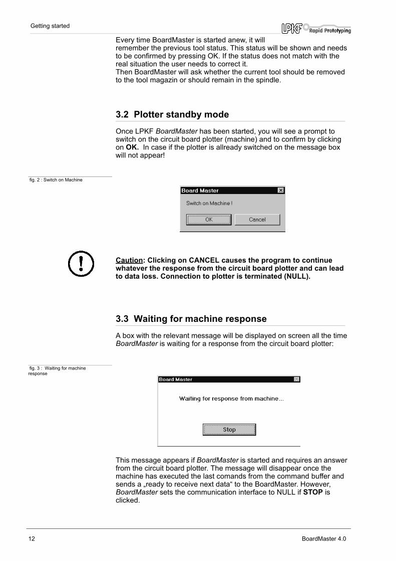
3.2 Plotter standby modeOnce LPKF BoardMaster has been started, you will see a prompt to switch on the circuit board plotter (machine) and to confirm by clickingon OK. In case if the plotter is allready switched on the message box will not appear!
fig. 2 : Switch on Machine
Caution: Clicking on CANCEL causes the program to continue whatever the response from the circuit board plotter and can lead to data loss. Connection to plotter is terminated (NULL).
3.3 Waiting for machine response A box with the relevant message will be displayed on screen all the time BoardMaster is waiting for a response from the circuit board plotter:
fig. 3 : Waiting for machine response
This message appears if BoardMaster is started and requires an answer from the circuit board plotter. The message will disappear once the machine has executed the last comands from the command buffer and sends a „ready to receive next data“ to the BoardMaster. However, BoardMaster sets the communication interface to NULL if STOP is clicked.
12 BoardMaster 4.0

Getting started
This is not an error message. It is possible to change to other applications while this message is being displayed. As soon as the plotter sends the response required to the PC, the message disappears and the program continues as normal.
3.4 BoardMaster user interface The illustration shows the BoardMaster user interface with the project "tutor.lmd" already imported:
fig. 4 :
A complete prepared production file, containing information regarding material size, LMD- or HP-GL files used, their placement and all production phases and tool assignments is referred to such a job.
The structure of a job file will be described in detail in the sections below.
You can import the "tutor.lmd" file for testing and practice purposes after you have started BoardMaster by selecting IMPORT - LMD from the FILE menu.
The BoardMaster user interface is divided up into a number of areas:
• The Title bar shows the name of the program and specifies the circuit board plotter type in use and the name of any job that has been loaded or freshly created.
• The Menu bar lists the menus available.
• The tool bar contains various buttons, displays and functions for controlling the circuit board plotter and for modifying a job.
• The Graphic Area shows the current view of the circuit board plotter in graphical form.
BoardMaster 4.0 13

Getting started
• This area is for its part divided into the actual working area of the circuit board plotter (shown in light grey) and the area of the board material in use (shown in dark grey) with the circuit board data to be processed. You can customize the graphical representation of the graphic area to your requirements using the VIEW menu functions.
• The Scroll bars beneath and to the right of the graphic area can be used to move the visible detail around the graphic area.
• The current mouse pointer position is shown on the left hand side of the horizontal scroll bar.
• The Status bar beneath the horizontal scroll bar shows information about the buttons, displays or areas where the mouse pointer is currently located.
14 BoardMaster 4.0

The Menu bar
4.0 The Menu bar
In this chapter we would like to introduce the menu functions in BoardMaster in a typical sequence in which they might be used.
4.1 The CONFIGURATION menu This menu groups together all the functions you might need in configuring BoardMaster and the connected circuit board plotter:
fig. 5 :
4.1.1 Serial interface
CAUTION:Make sure that no-one can access the working area of the circuit board plotter during the configuration procedure, as changing to the correct interface could cause a data transfer and thus cause the circuit board plotter to start.
Open the CONFIGURATION menu and select Connect... to open the following dialog box:
fig. 6 :
BoardMaster 4.0 15
The Menu bar
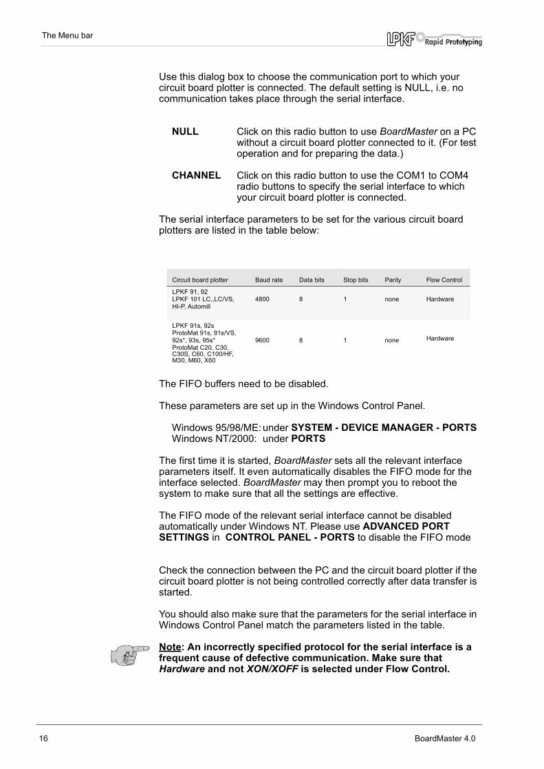
Use this dialog box to choose the communication port to which your circuit board plotter is connected. The default setting is NULL, i.e. no communication takes place through the serial interface.
NULL Click on this radio button to use BoardMaster on a PCwithout a circuit board plotter connected to it. (For testoperation and for preparing the data.)
CHANNEL Click on this radio button to use the COM1 to COM4radio buttons to specify the serial interface to whichyour circuit board plotter is connected.
The serial interface parameters to be set for the various circuit board plotters are listed in the table below:
The FIFO buffers need to be disabled.
These parameters are set up in the Windows Control Panel.
Windows 95/98/ME: under SYSTEM - DEVICE MANAGER - PORTS Windows NT/2000: under PORTS
The first time it is started, BoardMaster sets all the relevant interface parameters itself. It even automatically disables the FIFO mode for the interface selected. BoardMaster may then prompt you to reboot the system to make sure that all the settings are effective.
The FIFO mode of the relevant serial interface cannot be disabled automatically under Windows NT. Please use ADVANCED PORT SETTINGS in CONTROL PANEL - PORTS to disable the FIFO mode
Check the connection between the PC and the circuit board plotter if the circuit board plotter is not being controlled correctly after data transfer is started.
You should also make sure that the parameters for the serial interface in Windows Control Panel match the parameters listed in the table.
Note: An incorrectly specified protocol for the serial interface is a frequent cause of defective communication. Make sure that Hardware and not XON/XOFF is selected under Flow Control.
Circuit board plotter Baud rate Data bits Stop bits Parity Flow Control
LPKF 91, 92 LPKF 101 LC,,LC/VS,HI-P, Automill
4800 8 1 none Hardware
LPKF 91s, 92sProtoMat 91s, 91s/VS,92s*, 93s, 95s*ProtoMat C20, C30, C30S, C60, C100/HF, M30, M60, X60
9600 8 1 none Hardware
16 BoardMaster 4.0
The Menu bar
4.1.2 Circuit board plotter
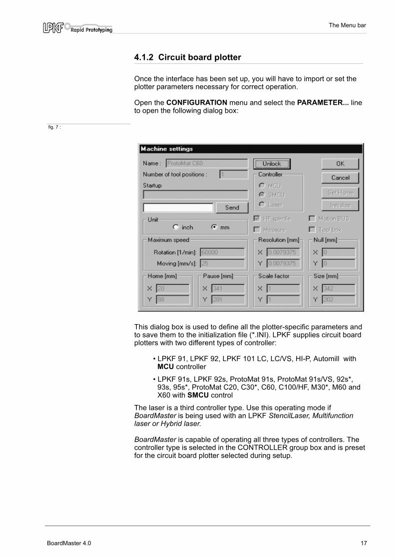
Once the interface has been set up, you will have to import or set the plotter parameters necessary for correct operation.
Open the CONFIGURATION menu and select the PARAMETER... line to open the following dialog box:
fig. 7 :
This dialog box is used to define all the plotter-specific parameters and to save them to the initialization file (*.INI). LPKF supplies circuit board plotters with two different types of controller:
• LPKF 91, LPKF 92, LPKF 101 LC, LC/VS, HI-P, Automill with MCU controller
• LPKF 91s, LPKF 92s, ProtoMat 91s, ProtoMat 91s/VS, 92s*, 93s, 95s*, ProtoMat C20, C30*, C60, C100/HF, M30*, M60 and X60 with SMCU control
The laser is a third controller type. Use this operating mode if BoardMaster is being used with an LPKF StencilLaser, Multifunction laser or Hybrid laser.
BoardMaster is capable of operating all three types of controllers. The controller type is selected in the CONTROLLER group box and is preset for the circuit board plotter selected during setup.
BoardMaster 4.0 17

The Menu bar
The controller type should not be changed, as otherwise correct data transfer with the appropriate syntax will no longer be possible.
To prevent accidental changes to a parameter listed in the CONFIGURATION SETTINGS dialog box, you are required to click the UNLOCK button to allow editing of a parameter before you carry out any intentional modification.
Machine parameter setting for MCU controller (only LPKF 101 LC, LC/VS, Hi-P, Automill)
All the important parameters for circuit board plotters with MCU controllers such as the HOME position (data origin) and the size of the working area are stored in battery-buffered RAM after plotter initialization. This data must be downloaded from the circuit board plotter before you start working with BoardMaster:
• Click on UNLOCK to allow modifications to machine parameters.
• Click on INITIALIZE to download the parameters from the circuit board plotter.
Notes:It is only possible to download the data from the circuit board plotter if the circuit board plotter controller is switched to Select.
Unless the origin of the circuit board plotter and/or the serial interface used is changed, definition of the connection and reading the HOME position and the working area is a one-time process, as this information is stored in the initialization file (*.INI) when you close BoardMaster.
The parameter values downloaded from the circuit board plotter are displayed in the ORIGIN, SIZE, HOME and PAUSE text boxes. The data in the NULL and SIZE text boxes are fixed values which are plotter-dependent and cannot be edited. The data in the HOME and PAUSE text boxes may be edited.
Changing the HOME position only causes changes of the display of the grphic area; it has no effect on the positioning of the data on the circuit board plotter, as the relevant HOME position for the circuit board plotter is stored in the controller.
It may be appropriate to modify the Pause position if it is to differ from the default setting (Xmax/Ymax), eg Xmax/Ymin.
18 BoardMaster 4.0

The Menu bar
Machine parameter settings for SMCU control (LPKF 91s, LPKF 92s and all ProtoMat models):
The machine parameters for your plotter are read during installation from the initialization disk that was supplied with your circuit board plotter. This means that all the important data for the machine size and the location of the HOME Position (data origin on the mirror axis) are already programmed in the factory. The plotter is ready to use.
All the important information such as the HOME position and the working area will be sent to the circuit board plotter controller by BoardMaster.
In case the machine specific INI file or the configuration disk get lost it might be necessary to initilaize the circuit board plotter anew.
Please follow the instructions below if you need to set these parameters anew or correct them.
Caution: The following instruction starts the circuit board plotter.
Previous parameter sets get lost.
Make sure that no-one can access the working area of the circuit board plotter.
You should also take account of additional safety instructions in the circuit board plotter manual.
› Click on UNLOCK to allow modifications to machine parameters.
› Click on INITIALIZE to start the initialization run.
The plotter head approaches the limit switches for all four travel directions during the initialization run and sends the values determined in this way back to BoardMaster. These values are displayed in the ORIGIN (Xmin/Ymin, always 0/0) and SIZE (Xmax/Ymax) text boxes. These entries cannot be edited, they can only be reset by initialization.
The values in the PAUSE text box are identical with the values in the SIZE text box. They can, however, be edited to place the Pause position at any chosen point.
Note: The values in the HOME (data origin) are set by default to Xmin and Ymax/2. The HOME values determined in this way are not the precise values which will ensure that the solder side and component side will coincide in the production of double-sided circuit boards. It is necessary to ensure that the HOME position lies precisely on the mirror axis of the plotter, which is established by the two alignment pins.
› Set up the Home position on the mirror axis of the circuit board plotter. (You can find information on how to do this in the circuit board plotter manual.)
› Click on SET HOME to set the Home position to the current position of the circuit board plotter's head.
BoardMaster 4.0 19
The Menu bar
We recommend that you make a note of these values so that it is not necessary to set up the HOME position on the circuit board plotter if the values are accidentally changed.
A command chain in the plotter syntax can be entered in the START LINE text box. This will be stored in the initialization file when you exit from BoardMaster and sent to the circuit board plotter each time you start BoardMaster.
All entries in the MACHINE PARAMETERS dialog box are sent to the circuit board plotter when you click on OK and saves to the initialization file when you exit BoardMaster. This means that they will be available the next time you start the program.
Further parameters
UNIT Clicking on one of these two radio buttons selects inch ormetric display for the length, diameter, coordinatesinformation, etc.
TYPE This text box displays the circuit board plotter type that willbe displayed in the BoardMaster title bar. This data is forinformation only and is of no significance for operation.
NUMBER OF TOOL HOLDERS The number in this box indicates the number of tool changepositions. This is always 1 for the LPKF 91, 92, ProtoMat© 91s,92s, 93s, ProtoMat c- and M-series and LPKF101 LC,LC/VS, and HI-P circuitboard plotters, always 7 for theLPKF Automill and always 30 for ProtoMat© 95s* circuitboard plotters.
SEND Clicking on this button sends the command, typed in the textbox to the left of the button, to the circuit board plotter.It is not necessary first to click on the UNLOCK button forthis function. Please consult the circuit board plotter manualfor the command syntax.
ROTATION SPEEDThe number in this box specifies the maximum speed of thecircuit board plotter spindle.
MOVING SPEEDThe number in this box specifies the maximum travel speedof the circuit board plotter spindle. This has higher prioritythan the tool speed (see TOOL PARAMETERS dialog box).
RESOLUTION The numbers in these two text boxes define the distancetraversed by the circuit board plotter for one step of thestepper motor in the X or Y direction. These values shouldnever be changed, as otherwise it is no longer possible toguarantee proper scaling of the output.
None of these parameters should be changed (except SEND) to avoid malfunction!
20 BoardMaster 4.0

The Menu bar
4.1.3 Tool parameters
The BoardMaster includes tool libraries listing the tools supplied by LPKF with all the tool- specific parameters. The tool library files come in three variants: *.TOL for drilling and milling tools, *.DIS for dispensing nozzles and *.VAC for suction nozzels (only used with LPKF AutoContac).
The TOOL LIBRARY sub menu of the CONFIGURATION menu gives you access to the various tool libraries:
fig. 8 :
Libraries:Samples for a ProtoMat C60:
FR4-60.tol - working with FR4 basis materialFR3-60.tol - working with FR3 basis materialAlu-60.tol - working with Alu basis materialFilm-60.tos - working with film foliesKapt-60.tol - working with solder stemcil foilsPlastics.tol - working on plasic material
FR4-60.tol was loaded as default. Please choose library depending on the material.
Select MILL/Drill from the CONFIGURATION - TOOL LIBRARY menu to open the following dialog box:
fig. 9 :
BoardMaster 4.0 21

The Menu bar
The various tool libraries define all tool specific parameters depending on the different plotter and application type. The parameters are described here to assist you in modifying or inserting additional tools.
NAME The name of the tool is listed in this list box. The nameyou choose if generating a new tool must be the same as used in CircuitCAM in order to enable an automaically toolassignment if importing the production data fromCircuitCAM. Selecting a tool from this list box allows you todisplay and, where necessary, modify its parameters.
DIAMETER The number in this text box specifies the diameter of the tool.This information allows the system to display the actualdiameter of the tool in the BoardMaster tool bar and will beused for the automatic tool assignment as well.
HEAD DOWN TIME The number in this text box indicates the time interval inseconds between "Head down" and "Head up" commandsfor the drilling tool, between „Head down“ command andstart of milling respectively.
MILL/DRILLClicking on one of these two radio buttons defines the tool asa milling tool or drilling tool.
DESCRIPTIONThis text box is provided for an additional description of thetool. This information is of no significance for the productionprocess.
LIFE CYCLEThe number in the MAXIMUM text box specifies themaximum milling distance or the maximum number ofdrills for the tool. The CURRENT text box displays the distance already milledby the tool or the current number of drills made by thetool. Clicking on REPLACE starts the tool change procedureand resets the content of the CURRENT text box to 0 oncethe old tool has been replaced.
OPTIMAL SPEED The number in the SPEED text box specifies the optimumspeed of the drilling spindle. The number in the MILLINGtext box defines the optimum feeding for milling tools.
Note: The speed of rotation is only used automatically for the LPKF ProtoMat© circuit board plotters with variable spindle speed. In the case of all other circuit board plotters with variable motor speed (e.g. LPKF 101 LC/VS), the optimum speed of rotation must be set manually on the controller. The optimum speed of rotation to be set is, however, indicated by BoardMaster on a tool change.
All changes to the tool library could be saved in the tool library file (*.TOL) for later reuse. The file which is loaded with the start of
22 BoardMaster 4.0
The Menu bar
BoardMaster is specified in the #include section of the *.MCH file.Also the valid production phase file (*.phs) and the dispenser (*.dis) and vacuum (*.vac) tool files are specified there.
By pressing the Save button, all changings will be saved in the current tool library file (*.TOL). The name of the current file is displayed above the tool listing.By pressing the Load button, you can load other tool libraries. Close the tool library dialog box by pressing OK or Cancle.
Dispenser, Vacuum: These dialog boxes contain all the important parameter required for dispensing and removing the conductive pastefor the AutoContac system and for dispensing other media. These processes are explained in more detail for their users below in this manual (see „LPKF AutoContac“ on page 50).
4.1.4 The Heads dialog box
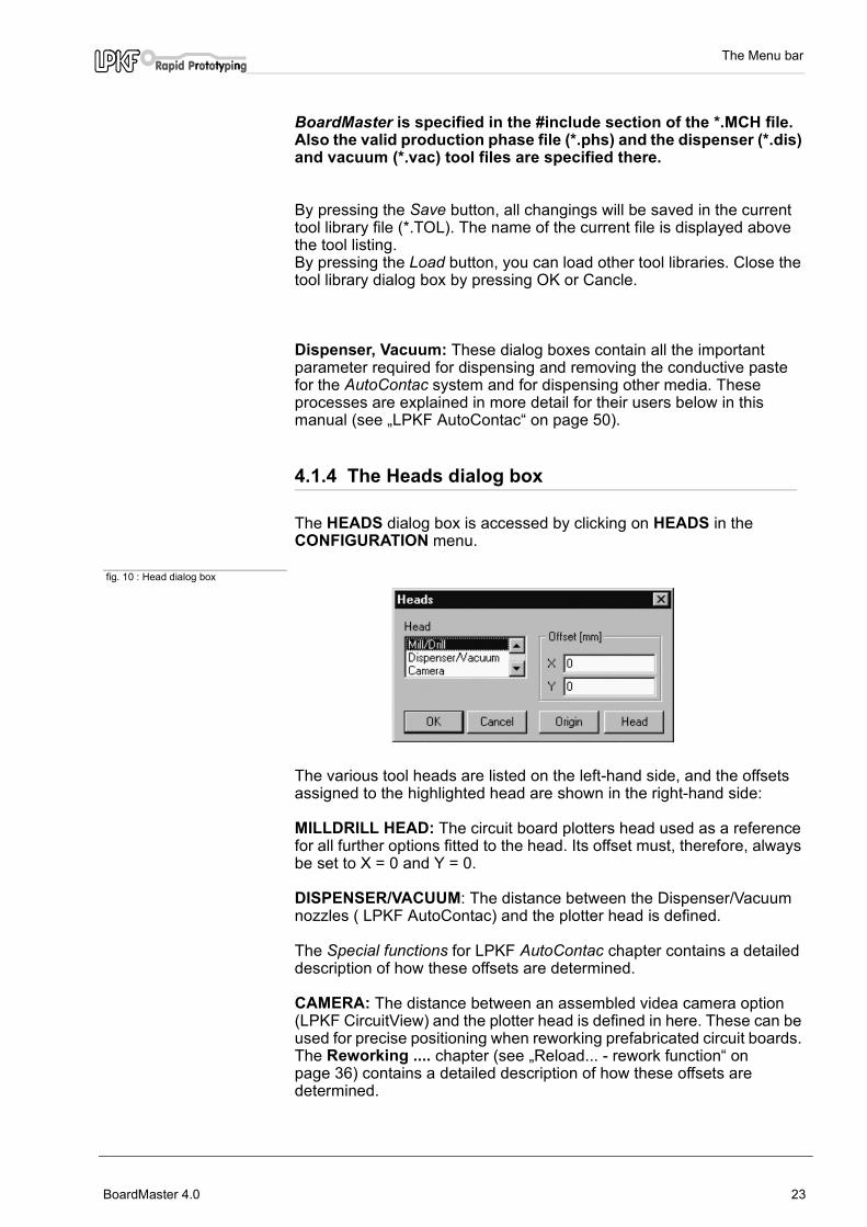
The HEADS dialog box is accessed by clicking on HEADS in the CONFIGURATION menu.
fig. 10 : Head dialog box
The various tool heads are listed on the left-hand side, and the offsets assigned to the highlighted head are shown in the right-hand side:
MILLDRILL HEAD: The circuit board plotters head used as a reference for all further options fitted to the head. Its offset must, therefore, always be set to X = 0 and Y = 0.
DISPENSER/VACUUM: The distance between the Dispenser/Vacuum nozzles ( LPKF AutoContac) and the plotter head is defined.
The Special functions for LPKF AutoContac chapter contains a detailed description of how these offsets are determined.
CAMERA: The distance between an assembled videa camera option (LPKF CircuitView) and the plotter head is defined in here. These can be used for precise positioning when reworking prefabricated circuit boards. The Reworking .... chapter (see „Reload... - rework function“ on page 36) contains a detailed description of how these offsets are determined.
BoardMaster 4.0 23

The Menu bar
X offset, Y offset:
These values specify the distance between the AutoContac nozzles or the camera and the mill/drill spindle in the X and Y directions. These values differ for the various types of cartridge toolholders and are in the range of 32 to 35 mm for X and 30 to 37 mm for Y.
Once the offsets have been determined, they should only be corrected if the nozzles or the camera are not positioned exactly centered over the drillings in the circuit board for dispensing, suction or viewing. An increase in the value corresponds to a displacement of the nozzles/camera relative to the mill/drill spindle in the positive X or Y direction.
Important:The maximum size of the working area is smaller for the use of dispenser or camera than those for drilling and milling by these amounts. The restricted grapfic area will be indicated by a white frame if a dispensing tool or suction tool is selected.
You can use this white frame to correctly place a project with dispensing and vacuum phases correctly on the printed board. Do this by selecting a dispensing and suction tool in the TOOL combo box (tool bar top left). The white frame will then be visible.
4.1.4.1 New determination of the offsets
CAUTION:Make sure that no-one can access the circuit board plotter's working area while you are redetermining the offsets. Entering the following commands has an immediate consequence on the circuit board plotter.
The procedures for re-specifying these offsets are as follows:
› Select the SPIRAL DRILL 0.5 MM tool from the TOOL combo box.
› Insert a 0.5 mm drill.
› Manually position the plotter head over the circuit board (using the arrow keys or the mouse).
› Switch on the motor and drill a hole using the Down button.
› Change to the HEADS dialog box, select DISPENSER and click on REFERENCE POINT.
› Now select the D PINK CARTRIDGE 0.5 MM tool, take the drill out and insert a cartridge with a needle (pink) in the holder.
› Manually (using the arrow keys) shift the needle as precisely as possible over the drill hole in the circuit board . You will have to use manual control through the arrow keys to do this see „MATERIAL - Base material size“ on page 26.
› Press the head down by hand and visually check the position of the needle in the X and Y direction, correcting as appropriate.
› Change back to the HEADS dialog box, select DISPENSER and click on HEAD.
24 BoardMaster 4.0
The Menu bar
The offsets will be computed by BoardMaster and entered. These values should also be used for the VACUUM head. When you exit BoardMaster, these values will be saved to the INI file and loaded again the next time you start the program.
4.1.5 PHASES - Production phases
All the data to be sent by BoardMaster to the circuit board plotter must be assigned to a specific production phase. These production phases embrace an operation in which the user does not need to intervene. An intervention might be, for instance, through-hole plating of the circuit board or turning the board material over. The sole exception to this rule is a manual tool change. This assignment is prepared in CircuitCAM and is automatically implemented in BoardMaster.
Some production phases are already defined in the initialization file. You can, however, modify these production phases to meet your requirements at any time. The names for the production phases must be the same in CircuitCAM and BoardMaster.
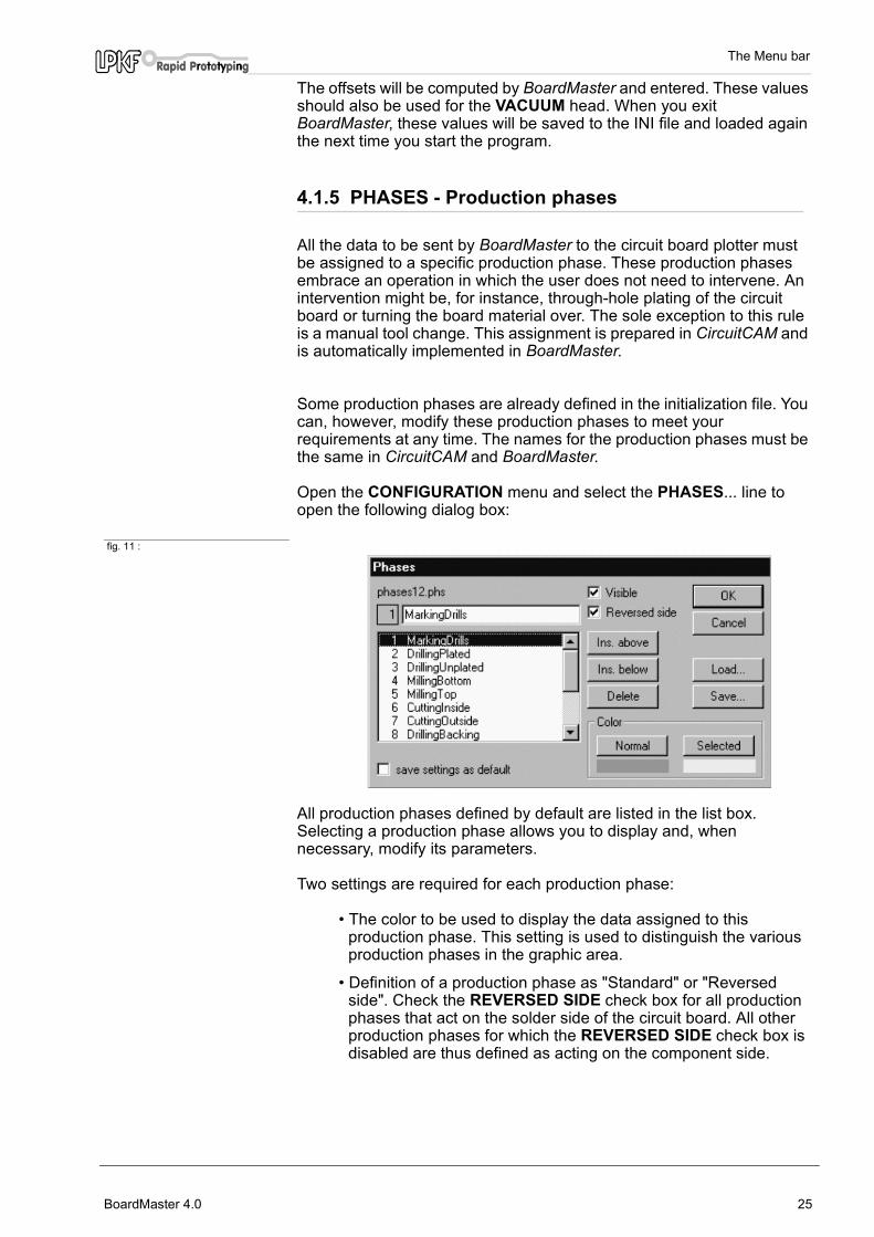
Open the CONFIGURATION menu and select the PHASES... line to open the following dialog box:
fig. 11 :
All production phases defined by default are listed in the list box. Selecting a production phase allows you to display and, when necessary, modify its parameters.
Two settings are required for each production phase:
• The color to be used to display the data assigned to this production phase. This setting is used to distinguish the various production phases in the graphic area.
• Definition of a production phase as "Standard" or "Reversed side". Check the REVERSED SIDE check box for all production phases that act on the solder side of the circuit board. All other production phases for which the REVERSED SIDE check box is disabled are thus defined as acting on the component side.
BoardMaster 4.0 25

The Menu bar
How to create a new production phase:
› Select the production phase before or after which you wish to insert the new production phase.
› Enter the name for the production phase in the text box.
› Click on INSERT ABOVE or INSERT BELOW to insert the production phase at the appropriate point in the list box.
› Press SAVE to save all changes to the current phases file (*.PHS). To load other phases files press Load.
Note: When milling single sided boards, „Reversed side“ should be enabled for the drilling phase. This will prevent you from having to turn the base material!
4.1.6 MATERIAL - Base material size
The first task in preparing a new job is to define the size of the base material to be used. This is necessary to ensure that the available area for operations is displayed in the graphic area, thus permitting the optimum placement of the circuit board data.
The board size is defined under MATERIAL of the CONFIGURATION menu:
fig. 12 :
This sub menu offers two options for the definition of board size:
• Manual input in the SIZE dialog box
• Determine the size by allowing the circuit board plotter to travel
Manual input in the SIZE dialog box
Open the CONFIGURATION MATERIAL sub menu and select SIZE... to open the following dialog box:
fig. 13 :
26 BoardMaster 4.0
The Menu bar
The size of the board material is specified by manually entering the appropriate values in the text boxes. The size calculated from the values entered in the two top text boxes is displayed in the SIZE text box.
The area of the board material will be displayed in dark grey on the graphic area once you quit the dialog box by clicking on OK .
Make sure that the minimum values (with a negative sign if necessary) are entered under Low Corner X/Y and the maximum values are entered under High Corner X/Y.
You should only use this option for specifying the size when preparing a job without the circuit board plotter connected, as it is not possible to specify this precisely taking into account the positioning on the circuit board plotter and the location of the registration pins in the plotters table.
Determine the size by allowing the circuit board plotter to travel
The board size is determined precisely when the circuit board plotters head is moved to use the SET Low Corner and SET High Corner functions found in the CONFIGURATION MATERIAL sub menu of the menu.
Caution: The following instruction starts the circuit board plotter.
Make sure that no-one can access the working area of the circuit board plotter.
You must also follow the safety instructions given in the manual for the circuit board plotter .
Manual control of the circuit board plotter is required for this process. Consult the capitel „manual control“ (see „Control functions for manual control“ on page 43) for information on this procedure.
› Move the plotter head to the "front, right corner" (X/Y min) of the
base material using the arrow keys. Ensure to take the registration pin position and the fixing tape ito consideration inorder to avoid placing your projects onto this locations.
› Select SET Low Corner from the CONFIGURATION MATERIAL sub menu.
› Move the plotters head to the "rear, left corner" (X/Y max) position of
the base material using the arrow keys.
› Select SET High Corner from the CONFIGURATION MATERIAL sub menu.
Once you have specified the base material size, the area will be shown in dark grey in the BoardMaster graphic area.
BoardMaster 4.0 27

The Menu bar
Make sure that the controller (standard controller) of the circuit board plotter series LPKF 91, 92 and LPKF101* is switched to Select when you are setting the two coordinates.
Make sure that you follow the specified sequence in setting the coordinates (first X/Y low corner , then X/Y high corner).
Take the fixing tape and the size of the working depth limiter into consideration when specifying the material size.
Any material size already defined will be deleted when you open a new job.
4.2 The GO TO menu This menu contains functions for moving the plotter head to the positions listed:
fig. 14 :
CAUTION:Selecting an entry from the GO TO menu causes the circuit board plotter connected to move.
Make sure that no-one can access the working area of the circuit board plotter or come into contact with the tools while the operations controlled by BoardMaster are being executed.
HOME Select this entry to move the plotter head to the HOMEposition (data origin).
PAUSE Select this line to move the plotter head to the PAUSE position (by default, this is Xmax/Ymax).
TOOL CHANGE POSITIONSelect this line to move the plotter head to the Tool changeposition (by default, this is Xmin/Ymin).
Camera >>Head Select this entry to move the camera to the current mill/drill
spindle position.
Head>>Camera Select this entry to move the mill-drill spindle back to its
original position.
28 BoardMaster 4.0

The Menu bar
4.3 The FILE menu The functions in this menu are used in handling jobs and projects in BoardMaster:
fig. 15 : File menu
NEW Select this item to create a new job in BoardMaster.
OPEN Select this item to open an existing job.Also Job files from BoardMaster 3.x can be loaded, butthe tool assignment has to be done again, because thetool names are different in this version.
SAVE Select this item to save the job opened in BoardMasterunder the filename shown in the BoardMaster title bar.
SAVE AS...Select this item to save the job opened in BoardMasterunder a new filename.
IMPORT This sub menu contains functions for importingproduction data or projects into BoardMaster:
fig. 16 :
LMD OR LPR...Select this item to import LMD files (CircuitCAMproduction data) or LPR files (BoardMaster HP-GLprojects) into BoardMaster. Also LMD files fromBoardMaster 3.x can be imported, but the toolassignment has to be done again, because the toolnames are different in this version.
HP-GL INTOSelect
NEW LPR... from this submenu toimport HP-GL files into BoardMasterand to assign them to a new project.
<DEFAULT> from this submenu to import HP-GLfiles into BoardMaster and assign themto the Default project.
BoardMaster 4.0 29

The Menu bar
The data is automatically placed in the centre of the circuit board plotter work area or the predefined base material respectively when LMD files are imported. Furthermore, the production phases and tools required are automatically assigned to the data. If BoardMaster is unable to assign one or more tools, the following message box will appear:
fig. 17 :
You will then have to assign the tools manually in the tool assignment dialog box, add needed tool to the tool library or load the proper tool library before importing the data again.
All the tools required will be listed in the CircuitCAM report window after the data is exported.
4.4 The EDIT menu
fig. 18 :
30 BoardMaster 4.0

The Menu bar
4.4.1 Tool Assignment ...
Every job in BoardMaster is composed of one or more projects. The circuit board data imported here as an LMD or HP-GL file is known as a project.
Import the sample file Tutor.LMD by choosing Import - LMD to load a project. Open the EDIT menu and select TOOL ASSIGNMENT to open the following dialog box:
fig. 19 :
The production data is generally imported using the import function from the file menu. These projects can, however, also be added (LMD file from CircuitCAM) or generated (HP-GL files) at this point.
Every LMD file created during export in CircuitCAM contain the production data for the whole PCB to be produced. The imported LMD files are listed in the project list box. In the Phase File/Layer list box every CircuitCAM layer with its production phase (Phase) is listed. Each of the items contain 1 or more tool information (Pen) with the assigned tool from the BoardMaster tool library (Tool).In case the tool assignment could not be done automatically (see message box above) it needs to be done in here:
› Select the layer from the listing which misses the assignment.
› Open the Pen list box and check that each pen has a tool assigned.
› If not, choose from the Tool list box the to be assigned tool.
Repeat this till all tools have been assigned correctly.
BoardMaster 4.0 31

The Menu bar
How to create a new project:
› Click on CREATE PROJECT to create a new project.
› Assign a name to the project in the ENTER NEW LPR NAME dialog box:
fig. 20 :
› Click on OK to close the dialog box.
› Enter the resolution of the HP-GL files associated with the project in the UNIT text box.
HP-GL files have a default resolution of 0.025 mm. Please change the setting for the HP-GL unit in the Machine Settings dialog box if you wish to use data with a different resolution.
› Click on ADD FILES... to add the selected HP-GL files to your project.
All the HP-GL files for a project must be located in the same folder.
› You must further also assign the following information under FILE/LAYER to any file containing production data:
PHASE Select the phase to which the production data are tobe assigned from this list box.
PEN/TOOLSelect from the PEN list box the pen from the HP-GL file to which the tool selected in the TOOL listbox is to be assigned.
Y=>-Y Enable this check box to allow simultaneous display of both sides of the circuit boardin the case the production data was created asmirror images. (Generally the solder side in allproduction data.)
› Click on SAVE AS... to save the project as an LPR file.
To open a project saved as an LPR file when you start the BoardMaster program, you should select LMD OR LPR... line of the IMPORT sub menu of the FILE menu.
32 BoardMaster 4.0
The Menu bar
Or:
› Click on ADD PROJECT... to add a project. This project may be an LMD file generated by CircuitCAM or an LPR file (HP- GL project file) generated in BoardMaster.
4.4.2 Placement ...
Once you have imported or generated the projects you require, you will be able to place them in the BoardMaster graphic area. Imported projects are automatically placed in the center of the graphic area.
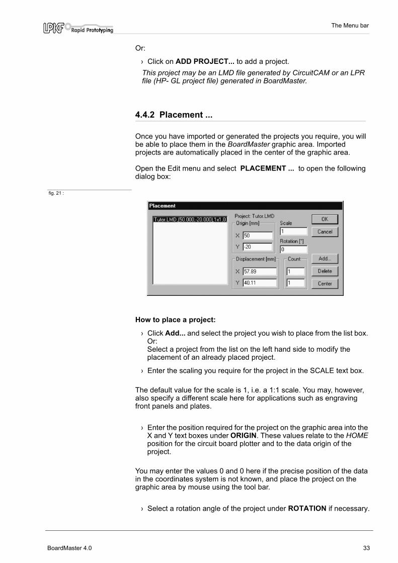
Open the Edit menu and select PLACEMENT ... to open the following dialog box:
fig. 21 :
How to place a project:
› Click Add... and select the project you wish to place from the list box. Or:Select a project from the list on the left hand side to modify the placement of an already placed project.
› Enter the scaling you require for the project in the SCALE text box.
The default value for the scale is 1, i.e. a 1:1 scale. You may, however, also specify a different scale here for applications such as engraving front panels and plates.
› Enter the position required for the project on the graphic area into the X and Y text boxes under ORIGIN. These values relate to the HOME position for the circuit board plotter and to the data origin of the project.
You may enter the values 0 and 0 here if the precise position of the data in the coordinates system is not known, and place the project on the graphic area by mouse using the tool bar.
› Select a rotation angle of the project under ROTATION if necessary.
BoardMaster 4.0 33

The Menu bar
› Specify the number of step-and-repeats under COUNT. Enter the number of boards in the X direction in the first text box and the number of boards in the Y direction in the second text box. Note: values should never be smaller than 1.
› Specify the spacing between the single pcb under DISPLACEMENT. The spacing between boards must be at least as great as the circuit board width or length, respectively, as otherwise the uses would overlap.
Panelisation (Step-and-repeat) can also be created using the tool bar.
How to place a project centred on the base material:
› Select the appropriate project from the list box.
› Click on CENTER to place the project selected centrally on the base material. If no base material has been defined BoardMaster places the project in the center of the plotters working area.
How to add further projects for placement:
› Click on ADD... .
› Select the project you also wish to place on the graphic area from the list box:
fig. 22 :
› Click on OK to close the dialog box.
How to remove a project that has already been placed:
› Select the appropriate project from the list box.
› Click on DELETE to remove the project from the base material again. The project remains within the Edit - Tool Assignment dialog box.
34 BoardMaster 4.0

The Menu bar
4.4.3 Tool Selection ...
The Tool Selection dialog box is used to disable specific tools for aproduction phase, in order to restrict the operations with those tools.
This dialog box shows all required tools within the current product phase. As default all the tools in the list are marked (enabled) i.e. all tools will be used if you will start the current production phase.
By clicking on one of the tools you can toggle between enabled (bleu background) and disabled (white background). Disabled tools will not been used during running the current production phase although they are part of the project.
fig. 23 : Select Tools
Example:A blunt drill bit has been used for drilling. For that reason the drills were not all the way through the board or the tool got broken. Only those drillings will be done again with this tool if the other tools of the list are disabled.
In addition you can choose if the smallest tool of the list (recommended for fine line milling) followed by the next bigger one or the current tool (for drilling, to reduce unnecessary tool changes) should be used first.
BoardMaster 4.0 35

The Menu bar
4.4.4 Check Drill ...
Open the Edit menu and select Check Drill ... to open the following dialog box:
fig. 24 : Check drill
If the check box „CHECK FOR BROKEN TOOLS“ is enabled BoardMaster will drill with any of the differnet drill tools within the current production phase one last drilling at the position specified here. Even if all drillings from the projects will be executed by optimization rules this final one will be always the last one, outside the project.
You easily can check whether a drill has been broken: If all the check drillings have been done, all the others of the projects must have been done as well.
Start Enter the X/Y coordinate for the position of theadditional check drillings.
Distance Enter the distance of drillings to each other.
Angle Enter an angle for the row of check drillings ifnecessary . 0° means drillings are parallel to theX- axis.
If the check box „Check for broken tools“ is enabled and you leave the dialog box with OK the additional drillings will be displayed in the graphic area as small squares. The Check Drill function is marked in the edit menu.
4.4.5 Reload... - rework function
The Reload function is used to rework a circuit board which has already been produced and cut to size, for example to add additional drillings, engrave labels or to separate the conductor tracks on circuit boards that have already been produced for coding purposes. The requirements to use the rework function are a PCB, which should be reworked, and the PCB data as LMD file containing at least two items (drillings, targets, corners) which can be assigned to the corresponding items on the PCB.
36 BoardMaster 4.0
The Menu bar
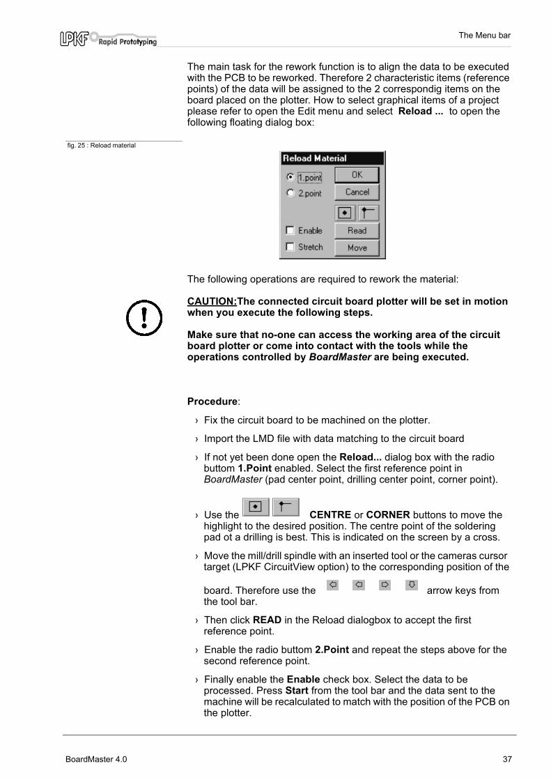
The main task for the rework function is to align the data to be executed with the PCB to be reworked. Therefore 2 characteristic items (reference points) of the data will be assigned to the 2 correspondig items on the board placed on the plotter. How to select graphical items of a project please refer to open the Edit menu and select Reload ... to open the following floating dialog box:
fig. 25 : Reload material
The following operations are required to rework the material:
CAUTION:The connected circuit board plotter will be set in motion when you execute the following steps.
Make sure that no-one can access the working area of the circuit board plotter or come into contact with the tools while the operations controlled by BoardMaster are being executed.
Procedure:
› Fix the circuit board to be machined on the plotter.
› Import the LMD file with data matching to the circuit board
› If not yet been done open the Reload... dialog box with the radio buttom 1.Point enabled. Select the first reference point in BoardMaster (pad center point, drilling center point, corner point).
› Use the CENTRE or CORNER buttons to move the highlight to the desired position. The centre point of the soldering pad ot a drilling is best. This is indicated on the screen by a cross.
› Move the mill/drill spindle with an inserted tool or the cameras cursor target (LPKF CircuitView option) to the corresponding position of the
board. Therefore use the arrow keys from the tool bar.
› Then click READ in the Reload dialogbox to accept the first reference point.
› Enable the radio buttom 2.Point and repeat the steps above for the second reference point.
› Finally enable the Enable check box. Select the data to be processed. Press Start from the tool bar and the data sent to the machine will be recalculated to match with the position of the PCB on the plotter.
BoardMaster 4.0 37

The Menu bar
Enabling the check box Stretch will stretch or shrink the data according to the real dimension of the board.
Note: The rotation or shifting eventually happend to the data is not displayed on the graphic area.
› After finishing rework completely, disable the Enable check box to avoid “mis-alignment“ of the data for later non-rework-jobs and close the dialog box by clicking on OK.
4.5 The VIEW menu You can customize the graphical representation of the BoardMaster graphic area to your requirements using the VIEW menu functions.
fig. 26 : View menu
ZOOM AREA Select this function to have any detail of thegrapfic area zoomed to full screen display. Do thisby clicking the left mouse button and holding it downwhile you cover the area required.
You can also select this function by clicking on in the tool bar.
ZOOM IN 1.5x Select this function to enlarge the graphicalrepresentation by a factor of 1.5.
ZOOM OUT 1.5xSelect this function to reduce the graphicalrepresentation by a factor of 1.5.
MACHINE Select this function to display the full working areaof the circuit board plotter configured in thegrapfic area.
MATERIAL Select this function to display the full board materialarea in the grapfic area.
ALL PROJECTSSelect this function to display all the placed projectsas large as possible in the grapfic area.
PREVIOUS Select this function to display the previousscreen detail again.
38 BoardMaster 4.0

The Menu bar
BOTH SIDES Select this function to toggle between simultaneousdisplay of both sides of a circuit board and displayof one side of the circuit board only.
TRUE WIDTH Select this function to switch on or off display of themilling lines in their true width. The true width of the milling lines is defined by thetool diameter in the tool library.
DEFAULT FONT Select this function to togglebetween the BoardMaster default font and the fontspecified under CHANGE FONT for text display.
CHANGE FONT...Select this function to select the font to bedisplayed if the DEFAULT FONT option is disabled.
BoardMaster 4.0 39

The tool bar
5.0 The tool bar
The tool bar in BoardMaster contains functions for placing and copying projects on the board material and for controlling the connected circuit board plotter. In addition, the tool bar shows important status information relating to the current machining process.
5.1 Status information
fig. 27 : status information
-1-Current life cycle The value displayed here indicates the length milled or thenumber of drillings already completed by the current tool.The value displayed here is identical with the value displayed inthe PRESENT text box in the tool library dialog box.
-2-Maximum life cycle The value displayed here indicates the length that can bemilled or the number of drillings that can be completed by thecurrent tool.The value displayed here is identical with the value displayedin, the MAXIMUM text box in the tool library dialog box.
-3-Length to be milled in the current production phaseThe value displayed here indicates the milling length or thenumber of drillings to be completed in the current productionphase by the current tool.
-4-Communication port This field indicates the interface to which the data arebeing sent. NULL here means that the data are not being sentto any interface. If you move the mouse pointer over this displaypanel, the parameters set for the interface will be displayed inthe status bar.
-5-Data marked/selected This field indicates whether a section of the production phasedata has been Marked (P) Selected (F) or Partially marked/partially selected (P/F).
1 2 3 4 5 6 7
40 BoardMaster 4.0

The tool bar
-6-Current plotter head position This panel indicates the current position of the plotter head.
-7-Estimated processing time for the current production phase This panel indicates the estimated time in hours:minutesrequired to process the complete production phase.
5.2 Variable parametersYou may edit, and thus customize to your requirements, the entries listed here.
fig. 28 : Variable parameters
-1-Selected Tool This list box shows the tool being used for the currentproduction phase. Open the list box and select a different toolfor manual tool change. The plotter willmove to the toolchangeposition.
-2-Milling speed/drilling time The value displayed here indicates the milling speed or thedrilling time defined in the tool library for the tool displayed.You can increase or reduce this value by clicking on the arrowbuttons to the right of the field or type a specific value.
-3-Speed of rotation The value displayed here indicates the speed of rotationdefined in the tool library for the tool displayed.You can increase or reduce this value by clicking on the arrowbuttons to the right of the field or type a specific value. For plotters with variable spindle seed only.
-4-Current production phase This list box displays the current production phase. Open thelist box the change the production phase in order to machinethe requested data.
-5-Step width for manual control This text box defines the step width by which the plotter head ismoved on a click of one of the four arrow keys. You mayhighlight the text box and increase or reduce the value in fixedincrements using the + or - key or type a specific value.
1
2 3 4 5 6
BoardMaster 4.0 41

The tool bar
-6-Vector index Specify the vector index in this text box. An index isincremented for every line section, arc or drilling. Here you mayspecify, for instance, from which vector index machining shouldbe started or the range of vectors to be done.
5.3 Project Placement functions
Open the EDIT menu and select PLACEMENT... to bring up the PLACEMENT dialog box to help you accurately place the projects at their approximate position on the board material. Use the following functions on the tool bar in a second step to place the projects visually.
Move project Click this button to move a project around the board material.Place the mouse pointer over the project to be moved, click theleft mouse button and drag the project to the desired positionholding the mouse button down. The project is displayed as alight area while it is being moved.
Duplicate projectClick this button to duplicate a project and to place the copy on the board material.Place the mouse pointer over the project to be duplicated, clickthe left mouse button and drag the copy of the project to thedesired position holding themouse button down. The copy of the project is displayed as a light area while it isbeing duplicated.
You must click the appropriate button again each time you wish to move or duplicate a project.
Press the <ESC> key to cancel a function.
Click the right mouse button on a project to open the PLACEMENT dialog box and display the parameters for this project. You can, for instance correct the reference point values in this dialog box to place the projects on the same X or Y coordinate (in register). This may be useful if you wish to use a guillotine or saw for later dividing up a multiple use board.
You may also use the PLACEMENT dialog box to rotate a project - after placement with the mouse - by changing the ROTATE parameter.
42 BoardMaster 4.0
The tool bar
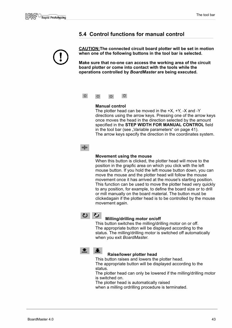
5.4 Control functions for manual control
CAUTION:The connected circuit board plotter will be set in motion when one of the following buttons in the tool bar is selected.
Make sure that no-one can access the working area of the circuit board plotter or come into contact with the tools while the operations controlled by BoardMaster are being executed.
Manual control The plotter head can be moved in the +X, +Y, -X and -Ydirections using the arrow keys. Pressing one of the arrow keysonce moves the head in the direction selected by the amountspecified in the STEP WIDTH FOR MANUAL CONTROL field
in the tool bar (see „Variable parameters“ on page 41).The arrow keys specify the direction in the coordinates system.
Movement using the mouse
When this button is clicked, the plotter head will move to theposition in the grapfic area on which you click with the leftmouse button. If you hold the left mouse button down, you canmove the mouse and the plotter head will follow the mousemovement once it has arrived at the mouse's starting position.This function can be used to move the plotter head very quicklyto any position, for example, to define the board size or to drillor mill manually on the board material. The button must beclickedagain if the plotter head is to be controlled by the mousemovement again.
Milling/drilling motor on/off This button switches the milling/drilling motor on or off. The appropriate button will be displayed according to thestatus. The milling/drilling motor is switched off automaticallywhen you exit BoardMaster.
Raise/lower plotter head This button raises and lowers the plotter head. The appropriate button will be displayed according to thestatus. The plotter head can only be lowered if the milling/drilling motoris switched on. The plotter head is automatically raisedwhen a milling ordrilling procedure is terminated.
BoardMaster 4.0 43

The tool bar
Milling/drilling mode You may use this button to toggle the controller mode betweenmilling and drilling. The appropriate button will be displayed according to thestatus.The speed of the milling tool or the drilling time of thedrilling tool will then be observed, depending on the modeactivated.A milling file will not be processed in drilling mode and,inversely, a drilling file will not be processed in milling mode.The mode will be set automatically with every tool change.
Automotor on/offYou may use this button to enable or disable automatic controlfor switching the motor on and off. ,The appropriate button will be displayed according to thestatus.When the Automotor function is enabled the milling/drillingmotor will be switched on at the start of a production phase andswitched off again when the phase is completed. The same istrue for tool change on circuit board plotters with manual toolchange. This function has a higher priority than the Motor on/off andRaise/lower plotter head functions. These two functions aredisabled if Automotor is enabled.In case the Automotor On/Off button is disabled the plotter willstart the production phase without switching on the spindle andlowering the head. This is for test run only.
5.5 Select production phaseYou must select the production phase to be processed first before the milling or drilling data can be sent to the circuit board plotter. This selection is made in the PRODUCTION PHASE list box of the tool bar:
fig. 29 : Select production phase
Choose the production phase to be processed next. Make sure that the production phase you select has also been assigned to an HP-GL file or the LMD file. An incorrect selection will either cause the incorrect files to be processed, or cause no data at all to be sent.
44 BoardMaster 4.0

The tool bar
Below we show an example of the sequence of production phases for a double-sided circuit board:
Process Production Phase
1. Drilling DrillingPlated
2. Milling the solder side MillingBottom
Turn the base material
3. Milling the component side MillingTop
4. Milling the contours CuttingOutside
BoardMaster 4.0 45

The tool bar
5.6 Tool change
5.6.1 Circuit board plotters with manual tool change
The TOOL list box in the tool bar lists all the tools of the tool library. This list is sorted, first shown the tools being used within the current production phase (marked with a "*") if a project is imported or a job is opened:
fig. 30 :
The first production phase will be active if no particular production phase has been selected.
If a tool will be selected from the list, the plotter head will move to the tool change position. At the same time, a message appears on screen stating that the tool just selected needs to be inserted into the collet.
Danger: This selection operates the Circuit Board Plotter automatically. You must also follow the safety instructions relating to tool changes given in the manual for the circuit board plotter.
Once you have changed the tool and confirmed the change by clicking on OK , the system can continue with further control commands.
Plotters with MCU controler needs to be switched to Select first.
During the computer controlled process of milling or drilling BoardMaster will manage the proper tool change
5.6.2 Circuit board plotters with automatic tool change
Automatic tool change is only possible with the circuit board plotters ProtoMat© 95s* or the LPKF101 Automill. If you now open the tool list box in the tool bar, you will not see a list of all tools, as it is the case with circuit board plotters with manual tool change, but rather only a list of the thirty (ProtMat 95s*) or seven (LPKF101 Automill) tool positions with the
46 BoardMaster 4.0

The tool bar
relevant tool assignment. These toolpositions represent the 30 or 7 positions of the plotters tool magazin.
Note: The <UNKNOWN> tool is assigned to each tool position after starting BoardMaster the very first time, i.e. no tool is entered. This is intended to force the user to check the tools in the circuit board plotter's magazines and to assign the corresponding positions in the TOOL POSITIONS dialog box.It is absolutely necessayr that the real tools in the tool magazin and the tools assigned in the tool position dialog box are exactly the same to avoid usage of wrong tools and therefore malfunction.
Open the TOOL POSITIONS dialog box by clicking with right mouse button on the TOOL list box:
fig. 31 : Tool positions
Assign the tools to the tool positions 1 to 30 (7 for the LPKF 101 Automill ) by selecting the tool required for the production phase in the appropriate list box. The WANTED FOR THE CURRENT PHASE list box lists the tools required for the production phase currently selected. This helps to ensure that all needed tools have been assigne to a tool position.The current life cycle of the assigned tools is given under Current. The maximum life cycle of the tools is shown under Maximum. The New check box needs to be checked if a used to in the toolmagazin has been replaced by a new one. This will set the Current life cycle back to 0.These tool position setting will be saved in the BoardMaster directory under *.tls when quiting BoardMaster. The list willbe automatically loaded when starting Boardmaster anew.
This dialog box will be opened automatically at the start of the production phase if a required tool has not been assigned to a tool position. You will only be able to continue once all tools have been assigned to a position.
BoardMaster 4.0 47

The tool bar
5.7 Selection functions Once the next production phase to be processed has been selected and the tool positions have been occupied (only required for automatic tool change), you will be able to select the data for this production phase to be sent to the circuit board plotter. It is only possible to send selected data for one production phase at a time to the circuit board plotter. The tool bar includes the following buttons for the selection of data:
Select all data Click this button to select all the data for the currentproduction phase.The selected data is shown in lighter color on the screen.
Cancel selectionClick on this button to cancel the current data selection.
Mark area (verctors inside and crossing the area) Click on this button to mark (preselect) a range of data. Dothis by clicking the left mouse button and holding it downwhile you cover the area required. This function also marksall the entire lines that cross the rubber-band selection. Themarked data are shown in white on the screen.
Mark area (only vectors inside area)Click on this button to mark (preselect) a range of data. Dothis by clicking the left mouse button and holding it downwhile you cover the area required. This function only markslines crossing the rubber-band selection as far as their firstpoint coordinate outside this area. The marked data areshown in white on the screen.
You must click the appropriate button again each time you wish to select an area. Press the <ESC> key to cancel a function.
Add marked data to the selectionClick on this button to add the marked (preselected) data tocurrent the selection.
Remove marked data from the selectionClick on this button to remove the marked (preselected) datafrom the current selection.
With these select function you are able to choose exactly those data you want to process.
48 BoardMaster 4.0
The tool bar
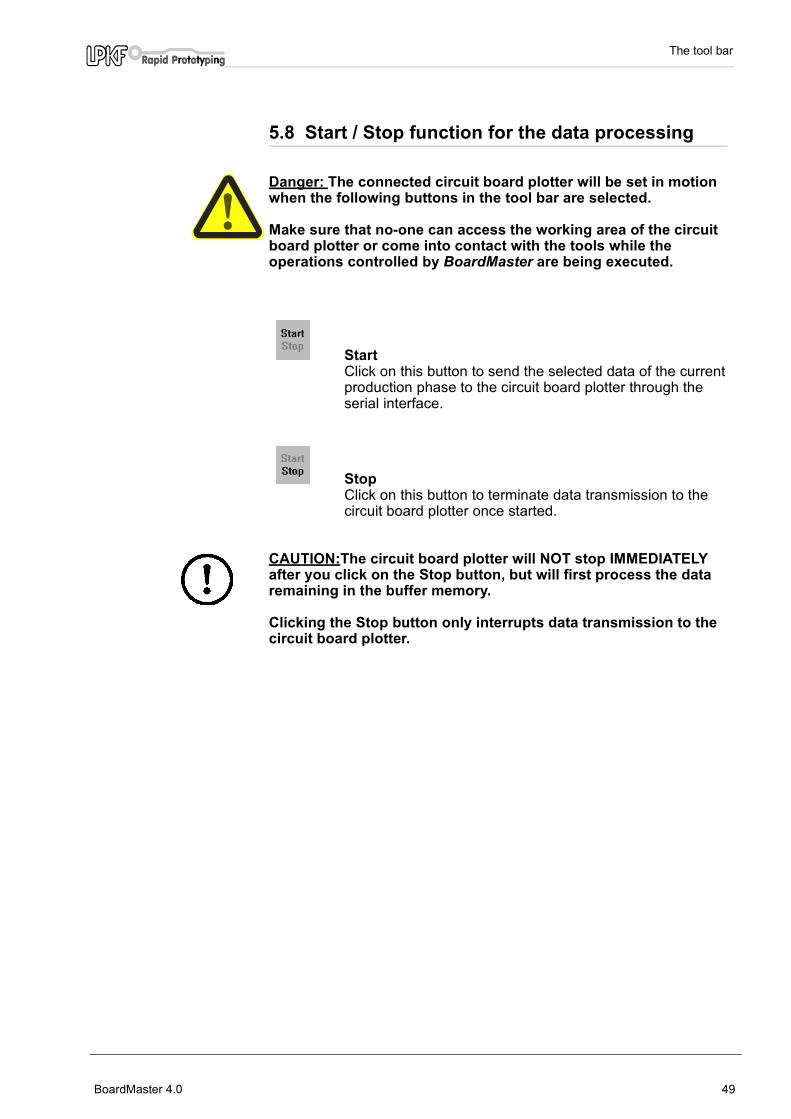
5.8 Start / Stop function for the data processing
Danger: The connected circuit board plotter will be set in motion when the following buttons in the tool bar are selected.
Make sure that no-one can access the working area of the circuit board plotter or come into contact with the tools while the operations controlled by BoardMaster are being executed.
StartClick on this button to send the selected data of the currentproduction phase to the circuit board plotter through theserial interface.
Stop Click on this button to terminate data transmission to thecircuit board plotter once started.
CAUTION:The circuit board plotter will NOT stop IMMEDIATELY after you click on the Stop button, but will first process the data remaining in the buffer memory.
Clicking the Stop button only interrupts data transmission to the circuit board plotter.
BoardMaster 4.0 49
Special functions
6.0 Special functions
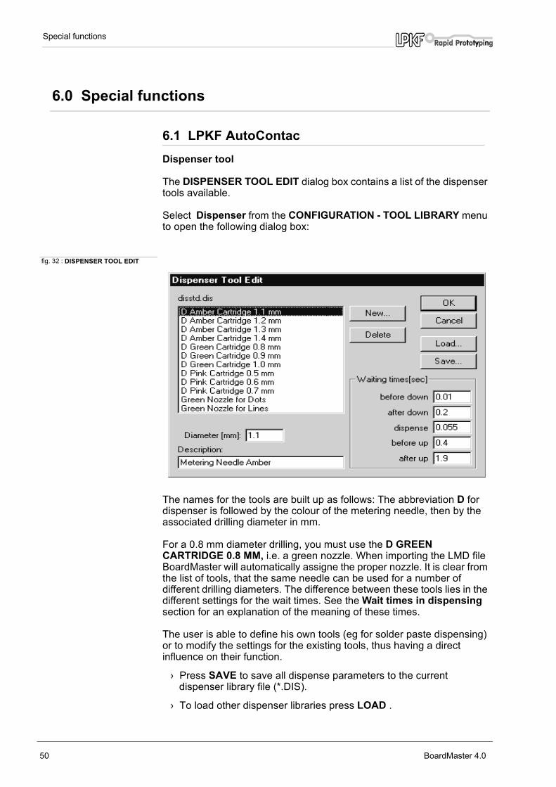
6.1 LPKF AutoContac Dispenser tool
The DISPENSER TOOL EDIT dialog box contains a list of the dispenser tools available.
Select Dispenser from the CONFIGURATION - TOOL LIBRARY menu to open the following dialog box:
fig. 32 : DISPENSER TOOL EDIT
The names for the tools are built up as follows: The abbreviation D for dispenser is followed by the colour of the metering needle, then by the associated drilling diameter in mm.
For a 0.8 mm diameter drilling, you must use the D GREEN CARTRIDGE 0.8 MM, i.e. a green nozzle. When importing the LMD file BoardMaster will automatically assigne the proper nozzle. It is clear from the list of tools, that the same needle can be used for a number of different drilling diameters. The difference between these tools lies in the different settings for the wait times. See the Wait times in dispensing section for an explanation of the meaning of these times.
The user is able to define his own tools (eg for solder paste dispensing) or to modify the settings for the existing tools, thus having a direct influence on their function.
› Press SAVE to save all dispense parameters to the current dispenser library file (*.DIS).
› To load other dispenser libraries press LOAD .
50 BoardMaster 4.0

Special functions
Vacuum tools
The Vacuum Tool Edit dialog box contains a list of the vacuum tools available. These tools are similar nozzels as those for dispensing. They will be used with empty cartridges to suck off residual conductive paste using LPKF AutoContac
Select Vacuum from the CONFIGURATION - TOOL LIBRARY menu to open the following dialog box:
fig. 33 : VACUUM TOOL EDIT
The names of the suction tools are composed of the letter V followed by the colour of the metering needle used and finally the associated drilling diameter.
› Press SAVE to save all vacuum parameters to the current vacuum library file (*.VAC).
› To load other vacuum libraries press LOAD .
Control Buttons using Dispensing Production Phase
After choosing the Dispense or the Vacuum production phase and selecting the data to be sent to the plotter the control buttons in the tool bar change.
Raising/lowering head button (stroke)
Clicking the stroke button in the function bar on a milling tool(while the motor is turning) causes the head to be lowered.
Clicking the stroke button on a drilling, dispense or suction tool
BoardMaster 4.0 51
Special functions
causes the execution of a single drilling, dispense or suctioncycle.
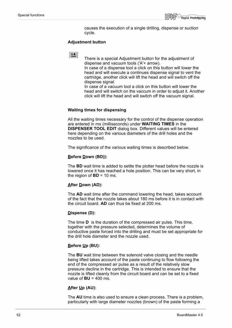
Adjustment button
There is a special Adjustment button for the adjustment ofdispense and vacuum tools ('A'+ arrow). In case of a dispense tool a click on this button will lower thehead and will execute a continues dispense signal to vent thecartridge, another click will lift the head and will switch off thedispense signal. In case of a vacuum tool a click on this button will lower thehead and will switch on the vaccum in order to adjust it. Anotherclick will lift the head and will switch off the vacuum signal.
Waiting times for dispensing
All the waiting times necessary for the control of the dispense operation are entered in ms (milliseconds) under WAITING TIMES in the DISPENSER TOOL EDIT dialog box. Different values will be entered here depending on the various diameters of the drill holes and the nozzles to be used.
The significance of the various waiting times is described below.
Before Down (BD)):
The BD wait time is added to settle the plotter head before the nozzle is lowered once it has reached a hole position. This can be very short, in the region of BD = 10 ms.
After Down (AD):
The AD wait time after the command lowering the head, takes account of the fact that the nozzle takes about 180 ms before it is in contact with the circuit board. AD can thus be fixed at 200 ms.
Dispense (D):
The time D is the duration of the compressed air pulse. This time, together with the pressure selected, determines the volume of conductive paste forced into the drilling and must be set appropriate for the drill hole diameter and the nozzle used.
Before Up (BU):
The BU wait time between the solenoid valve closing and the needle being lifted takes account of the paste continuing to flow following the end of the compressed air pulse as a result of the relatively slow pressure decline in the cartridge. This is intended to ensure that the nozzle is lifted cleanly from the circuit board and can be set to a fixed value of BU = 400 ms.
After Up (AU):
The AU time is also used to ensure a clean process. There is a problem, particularly with large diameter nozzles (brown) of the paste forming a
52 BoardMaster 4.0

Special functions
thread as the nozzle is raised. The AU wait time after the command to raise the head waits for these threads to break and prevents the tool head moving immediately; this prevents the paste thread being laid across the isolation track. AU can be set to shorter times for small needle diameters than for large diameters.
The graph below illustrates the function of the wait times in the dispense operation:
fig. 34 : Wait times in dispense
The graph above plots the position of the tool head, the changes in pressure in the cartridge and the exit speed of the paste against process time.
The gradient of the pressure pulse transitions is determined by the buffer effect of the air volume in the hose and the cartridge. The term min instead of 0 is intended to indicate that a weak vacuum is also present in the nozzle during the dispense procedure to prevent dripping. The vacuum is applied to the cartridge once the solenoid valve is closed.
Wait times for vacuum
All the wait times necessary for the control of the suction operation are entered in ms iunder WAITING TIMES in the VACUUM TOOL EDIT dialog box.
Before Down (BD):
This has the same meaning as during the dispense procedure.
Vacuum (V):
BoardMaster 4.0 53

Special functions
The time V between the commands for lowering and raising the tool head has an indirect influence on the contact time of the suction nozzle. A time of around 180 ms for the head to lower needs to be subtracted.
After Up (AU):
The AU wait time gives the paste sucked up time to pass through the needle into the cartridge. This ensures that the needle is free again before the next suction operation. AU can be set to a fixed value of 500 ms.
The graph below illustrates the function of the wait times in the suction operation:
fig. 35 : Times for the suction
The graph above plots the position of the tool head, the negative pressure in the cartridge and the flow rate of the paste in the drill hole against process time.
The vacuum level is fixed on the metering device. The maximum negative pressure is established in the cartridge when the nozzle is closed. The negative pressure in the cartridge falls to a greater or lesser degree, however, as air is sucked through the nozzle depending on the magnitude of the volume flow. The minimum negative pressure is established once the needle is completely free. This situation exists when the head is up.
When the suction nozzle is placed on the paste-filled drill hole, the negative pressure in the cartridge rises to the preset maximum negative pressure. This sucks the paste upwards through the drill hole into the nozzle. The negative pressure falls again when the drill hole is finally opened and air is sucked through it. The air flow in the drill hole forces the paste further up the hole side wall until the head lifts and the air flow through the drill hole is halted.
54 BoardMaster 4.0
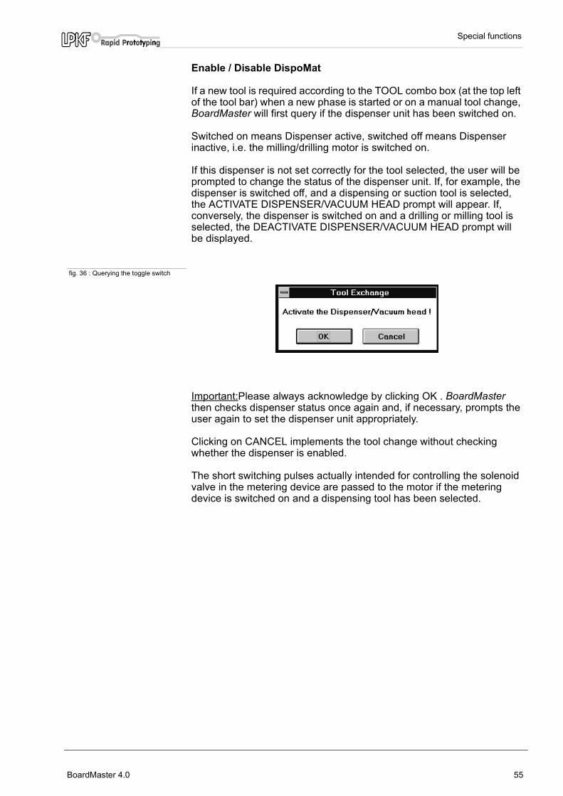
Special functions
Enable / Disable DispoMat
If a new tool is required according to the TOOL combo box (at the top left of the tool bar) when a new phase is started or on a manual tool change, BoardMaster will first query if the dispenser unit has been switched on.
Switched on means Dispenser active, switched off means Dispenser inactive, i.e. the milling/drilling motor is switched on.
If this dispenser is not set correctly for the tool selected, the user will be prompted to change the status of the dispenser unit. If, for example, the dispenser is switched off, and a dispensing or suction tool is selected, the ACTIVATE DISPENSER/VACUUM HEAD prompt will appear. If, conversely, the dispenser is switched on and a drilling or milling tool is selected, the DEACTIVATE DISPENSER/VACUUM HEAD prompt will be displayed.
fig. 36 : Querying the toggle switch
Important:Please always acknowledge by clicking OK . BoardMaster then checks dispenser status once again and, if necessary, prompts the user again to set the dispenser unit appropriately.
Clicking on CANCEL implements the tool change without checking whether the dispenser is enabled.
The short switching pulses actually intended for controlling the solenoid valve in the metering device are passed to the motor if the metering device is switched on and a dispensing tool has been selected.
BoardMaster 4.0 55

Special functions
6.2 Special Dialog Boxes and Functions forProtoMat© 95s / 95s/II
The Service Password dialog box
If service is required, clicking on SERVICE in the STATUS... and TOOL MAGAZINE... dialog boxes of the CONFIGURATION menu brings up the following screen prompting you to enter the password.
fig. 37 :
It is then possible to make changes to the settings in the dialog boxes concerned.
CAUTION:These changes may only be made by persons who have been trained in the functioning and operation of the ProtoMat© 95s.
You must observe the proper functioning of the machine and the safety regulations to avoid personal injury and damage to the machine. Enter the password [ bmaster ] if you are authorized to make changes.
56 BoardMaster 4.0

Special functions
The ToolBox I/O Status dialog box
Clicking on STATUS... opens the TOOL MAGAZINE I/O STATUS dialog box:
fig. 38 : The ToolBox I/O Status
The TOOL MAGAZINE I/O STATUS dialog box shows information regarding the signals set or which data lines are connected.
In is used to check the lines that are also connected for tool change, Out indicates which lines have been enabled by BoardMaster.
The Refresh button can be used to check whether any status changes made have been detected and accepted by the system.
BoardMaster 4.0 57

Special functions
The Tool Magazine dialog box
The TOOL MAGAZINE dialog box is accessed by clicking on TOOL MAGAZINE.... in the CONFIGURATION menu:
fig. 39 : The Tool Magazine
Here you can manually check the alignment positions preset by LPKF for automatic tool change. The user does not normally need to make any changes here. The numerical values entered indicate a sample configuration.
MAIN CLAMP AT EXCHANGE POS. indicates the position of the plotter head over the exchangestation.
AUXILLARY CLAMP AT EXCHANGE POS. indicates the position of the auxillary clamp over the exchangestation.
AUXILLARY CLAMP AT FIRST TOOL POS. indicates the position of the auxillary clamp over the firsttool in the tool magazine.
AUXILLARY CLAMP AT LAST TOOL POS.indicates the position of the auxillary clamp over the last tool.
Pressing the Read button will reset the coordinates to the coordinates of the current plotter head position. Doublecheck the ploter head position before clicking to Read. Clicking on MOVE then verifies this change.
These positions, and also HOME and SIZE, are preset in the factory (file BM-95PS2.INI).
CAUTION:Note that it is possible to overwrite the current positions and thus there is a hazard to the user and damage to the machine is possible.
58 BoardMaster 4.0

Special functions
DELAY indicates the wait time between the various commands.
HEAD SHIFT IN X DIRECTION indicates the plotter head travel in the X direction during a toolchange.
The status of the three combo boxes, MAIN CLAMP (of the plotter head), EXCHANGE CLAMP and TOOLBOX must correspond to the status when the TOOL MAGAZINE box is opened, otherwise it is not possible to quit the TOOL MAGAZINE box. These buttons can be used tosimulate an automatically tool change procedure.
Note:The plotter must be switched on and connected before you can quit the TOOL MAGAZINE box.
Any changes or actions within this dialog box needs to be enable by clicking on SERVICE and entering the a.m.password for safety reasons.
6.3 The Teach In dialog box BoardMaster has offered the function of programming drilling and milling data from a template (film or circuit board) using a Teach In process. This is done by fixing the template on the circuit board plotter and then travelling to the positions you wish to program by this method using a light spot or CircuitView camera as a guide. After programming, the HP-GL file can be imported into BoardMaster and output to the circuit board plotter.
The Teach In dialog box is displayed when you select TEACH IN from the EDIT menu.
fig. 40 : The Teach In dialog box
BoardMaster 4.0 59
Special functions
STEP [MM]:The values entered under X and Y (in mm) indicate the distance traveled for a single click of the travel buttons (+X, -X, +Y and -Y). A value of 2.54 mm must be entered here when programming the drillings for an IC, this corresponds to a pad spacing of 1/10".
HEAD:Clicking on one of these two radio buttons (UP, DOWN) programs the Head Down or Head Up commands. The head will remain in the chosen position until the other radio button is selected. This function is not used for the creation of a drilling file, but for programming milling or contour data.
RECORD MOVEMENTS:Enabling this check box causes all movement commands to be recorded in the file selected.
PEN:The pen number entered in this box is written to the selected file as a Select Pen command. This means that all drilling data, including that for different diameters, can be combined in one drilling file. Example: Pen 1 for 0.7mm, pen 2 for 0.9mm etc.
+X, -X, +Y, -Y:These buttons are used to move to a desired position. Clicking on one of these buttons causes the plotter head to move by the amount specified under STEP in the direction selected.
EXIT:Clicking on this button closes the TEACH IN module of BoardMaster and closes the drilling or milling file being recorded.
CREATE FILE:When this button is clicked, BoardMaster prompts you to name a file into which the data to be programmed will be saved. Here you may either create a new file or overwrite an existing file.
APPEND FILE:Clicking on this button allows you to select an existing drilling or milling file to which the additional drilling or milling data will be appended. The new data will be appended to the end of the file selected.
PEN [SP]:Clicking on this button adds the pen or tool number selected under Pen to the drilling or milling file as a Select Pen (SP) command. This is used to distinguish between different drilling diameters.
PLOT [PA]:This button can be used to move the head at angles other than 90(with the RECORD MOVEMENTS function deselected).
DRILL [PD;PU;]:This button is clicked to program a drilling operation once you have moved to the correct position. This writes the Pen Down, Pen Up command sequence to the file.This command sequence corresponds to a drill command for the circuit board plotter.
Procedure
› Set the unit appropriate for the machine resolution (0.0079375) in the EDIT PROJECT dialog box. (You will also find this value in the PARAMETERS dialog box of the Configuration menu.)
Please do not forget to reset the resolution to the original value when this operation is completed.
› Now open the TEACH IN dialog box to import the coordinates required.
60 BoardMaster 4.0

Special functions
Note here that a file has already been written for the data to be created; the coordinates will then be exported into this file in sequence. Do this by clicking on the Append file button. A new window in which you can assign a name to the file will open. You may use any extension for the file.
› Once you have entered the name, you will be returned to the TEACH IN dialog box. You must check the RECORD MOVEMENT option before you can begin importing data.
› The file to be created is an HPGL file which means that it will be written in the structure appropriate for an HPGL file. You should thus first click the Pen (SP) button to define a pen.
› Now move the head to the drill hole position to be imported using the movement buttons and click on the Drill (PD;PU) button.
› Once you have imported all the drilling data required, you should close the TEACH IN dialog box by clicking the EXIT button. The coordinates recorded will now be saved in the HPGL file previously created.
› If you now wish to produce a board using this newly entered data with BoardMaster and the machine, you must open the EDIT PROJECT dialog box. It is best first to create a new project by clicking on NEW PROJECT. You may then insert the associated HPGL file using ADD....
BoardMaster 4.0 61

Step by Step
7.0 Step by Step
This section once again runs through the principles behind the procedure for prototype production of a double sided not through hole plated PCB in BoardMaster step by step using a plotter without automatically tool change:
Start BoardMaster
› Click on the BOARDMASTER 4.0 icon under Program-LPKF40 in the Start menu or doubleclick the icon on the desktop to start BoardMaster.
Configuring BoardMaster
› If not been done yet define the serial interface by selecting the INTERFACE... line of the CONFIGURATION menu.
› Also check the settings for the serial interface under PORT in the WINDOWS CONTROL PANEL.
Specify board size
› Place the board material with the predrilled registration holes on the plotters table fitting to the registration pins.
› Specify the size of the board material to be machined using the SET X,Y MIN and SET X,Y MAX functions found in the MATERIAL sub menu of the CONFIGURATION menu.
Open or create the job
› Open an existing job by selecting OPEN... line from the FILE menu or create a new job by selecting the NEW line of the FILE menu.
Import production data
› Import LMD production data created by CircuitCAM or HP-GL project files already created by BoardMaster by selecting the LMD OR LPR... line from the IMPORT sub menu of the FILE menu.
Assign tools
› Assign the appropriate tools/phases to the imported production data or projects by selecting the TOOL ASSIGNMENT line of the EDIT menu if BoardMaster has not been able to complete the assignment itself.
Place production data
› Place the imported production data or projects by selecting the PLACEMENT... line from the EDIT menu or
62 BoardMaster 4.0

Step by Step
using the buttons in the tool bar.
Save job
› Save the job following placement of all projects by selecting the SAVE AS line from the FILE menu.
Select first production phase
› Select the production phase DrillingPlated to be processed from the PRODUCTION PHASE list box in the tool bar.
Enable Automotor
› Enable the Automotor function by clicking on in the tool bar.
Disabled function is indicated by a white slash through the icon .
Select data
› Select the data to be sent to the circuit board plotter using the selection buttons in the tool bar:
CAUTION:The connected circuit board plotter will be set in motion when the following button in the tool bar is selected.
Make sure that no-one can access the working area of the circuit board plotter or come into contact with the tools while the operations controlled by BoardMaster are being executed.
Start drilling/milling operation for the production phase selected
› Click on in the tool bar to send the selected data for the current production phase to the circuit board plotter via the serial interface.
BoardMaster 4.0 63

Step by Step
Select second production phase
› After finishing the drilling, select the production phase MillingBottom to be processed from the PRODUCTION PHASE list box in the tool bar.
Select data
› Select the data to be sent to the circuit board plotter using the selection buttons in the tool bar:
Start drilling/milling operation for the production phase selected
› Click on in the tool bar to send the selected data for the current production phase to the circuit board plotter via the serial interface. The tool change will be controlled by BoardMaster. Follow the instruction.
Turn the base material
› After finishing the drilling and milling of the bottom side of the PCB, move the plooter head to pause position (GO TO - PAUSE) and turn the base material by X axis.
Select third production phase
› After finishing tiurning the material, select the production phase MillingTop to be processed from the PRODUCTION PHASE list box in the tool bar.
Select data
› Select the data to be sent to the circuit board plotter using the selection buttons in the tool bar:
64 BoardMaster 4.0

Step by Step
Start drilling/milling operation for the production phase selected
› Click on in the tool bar to send the selected data for the current production phase to the circuit board plotter via the serial interface. The tool change will be controlled by BoardMaster. Follow the instruction.
Select fourth production phase
› After finishing the milling of the top side, select the production phase CuttingOutside to be processed from the PRODUCTION PHASE list box in the tool bar.
Select data
› Select the data to be sent to the circuit board plotter using the selection buttons in the tool bar:
Start drilling/milling operation for the production phase selected
› Click on in the tool bar to send the selected data for the current production phase to the circuit board plotter via the serial interface. The tool change will be controlled by BoardMaster. Follow the instruction.
The double sided board has been finished. If you need to process data of other production phases (dispense, milling inner layers of a multi layer baord etc.) follow the a.m. instructions in the same way.
BoardMaster 4.0 65

Index
8.0 Index
AADD FILES ......................................................................................................................32automatic tool change ...............................................................................................46Automill ..............................................................................................................................18Automotor on/off ...........................................................................................................44AUXILLARY CLAMP ..................................................................................................58
Bboard material ................................................................................................................14BOTH SIDES .................................................................................................................39Broken drills ....................................................................................................................36
CCAMERA/ .........................................................................................................................23Cancel selection ...........................................................................................................48Caution ................................................................................................................................4Check Drill .......................................................................................................................36circuit board data ..........................................................................................................14CONFIGURATION ......................................................................................................17CONTROL PANEL ......................................................................................................16Conventions ......................................................................................................................4
DDanger .................................................................................................................................4data loss ............................................................................................................................12DESCRIPTION ..............................................................................................................22DISPENSER ...................................................................................................................23DISPENSER TOOL EDIT ........................................................................................50dispensing ........................................................................................................................52DispoMat ..........................................................................................................................55DRILLING TIME ............................................................................................................22DRILLING/MILLING HEAD ...............................................................................21, 50
EEnable Automotor ............................................................................................63, 64, 65
FFILE menu .......................................................................................................................29Folders ...............................................................................................................................10
GGO TO menu ..................................................................................................................28
HHEAD ..................................................................................................................................23
66 BoardMaster 4.0

Index
HOME ................................................................................................................................ 28HP-GL ................................................................................................................................ 29Hybrid laser .................................................................................................................... 17
IINSERT ............................................................................................................................. 26interface ............................................................................................................................ 15
LLibraries ............................................................................................................................ 21LMD OR LPR ................................................................................................................. 29
MMACHINE ........................................................................................................................ 38MAIN CLAMP ................................................................................................................ 58Manual control .............................................................................................................. 43material size ............................................................................................................. 13, 26MCU controller .............................................................................................................. 18Menu bar .......................................................................................................................... 13MILL/DRILL .................................................................................................................... 22Milling/drilling mode .................................................................................................... 44Milling/drilling motor on/off ...................................................................................... 43monitor ................................................................................................................................ 8Move project .................................................................................................................. 42Movement using the mouse .................................................................................. 43MOVING SPEED ......................................................................................................... 20Multifunction laser ....................................................................................................... 17
NNote ...................................................................................................................................... 4NULL .................................................................................................................................. 16
OOPTIMUM SPEED ...................................................................................................... 22Orientation ......................................................................................................................... 4ORIGIN ............................................................................................................................. 33
PPARAMETER ................................................................................................................ 17PAUSE .............................................................................................................................. 28PLACEMENT ................................................................................................................. 33plotter head position .................................................................................................. 41pointer position ............................................................................................................. 14PREVIOUS ..................................................................................................................... 38processor ........................................................................................................................... 8Production phases ...................................................................................................... 25
RRaise/lower plotter head .......................................................................................... 43RESOLUTION ............................................................................................................... 20REVERSED SIDE ....................................................................................................... 25ROTATION SPEED .................................................................................................... 20
BoardMaster 4.0 67
Index
SSafety notes ......................................................................................................................7Save job ............................................................................................................................63Scroll bars ........................................................................................................................14Select all data ................................................................................................................48SEND ..................................................................................................................................20SET HOME ......................................................................................................................19SETTINGS .......................................................................................................................16SIZE dialog box .............................................................................................................26SMCU control .................................................................................................................19Start .....................................................................................................................................11Status bar .........................................................................................................................14symbols ...............................................................................................................................4System requirements ...................................................................................................8
TTeach In .............................................................................................................................59Title bar ..............................................................................................................................13TOOL CHANGE POSITION ...................................................................................28TOOL HOLDERS .........................................................................................................20TOOL LIBRARY ................................................................................................21, 50, 51Toolbar ...............................................................................................................................13TYPE ..................................................................................................................................20
UUNIT ....................................................................................................................................20
VVACUUM ..........................................................................................................................23Vector index ....................................................................................................................42
Wworking area ...................................................................................................................14
XX offset ...............................................................................................................................24XON/XOFF ......................................................................................................................16
YY offset ...............................................................................................................................24
68 BoardMaster 4.0