Embed Size (px)
Citation preview

Managing Your Building Automation System
Instructor’s Name: Richard Albrecht Mobile Phone: 636-328-7472

Honorable Mention
BOC – Building Operator Certification www.boccentral.org
ASHRAE Abtar Singh President, SINGH360 INC.

Definitions
BAS – Building Automated System
EMS – Energy Management System
BMS – Building Management System

EMS Architecture ENTERPRISE
BUILDING INTEGRATION DEVICE
UNIT CONTROLLERS

Protocols “Protocols are languages by which two devices communicate and exchange data.”
Language = English Media = Phone Dictionary

Protocol Levels •Device Level (Modbus, Canbus, BACNet etc.) •Building Level (BacNet, Proprietary etc.) •Enterprise Level (Web, XML)

Protocol Classification
•Proprietary
•Open (may or may not be standard)
•Standard and hence inter-operable

Proprietary Protocol •Only devices from same company know how to communicate –Language is secret –Dictionary is unpublished

Open Protocol
•When Protocol is published and readily available –May or may not be standard

Standard Protocol
•When everyone gets together and agree on language and dictionary: –BacNet –Modbus etc.

Inter-Operable
Standard + Open = Inter-operable
Inter-Operable

What is Best ?
•“Standard Protocol” is Ideal. •“Open” is second best. •“Proprietary” should not be preferred – At least ask BMS vendor to publish the protocol (make it open)

What is Practical? •Unit Level: –Modbus –BacNet etc. –Proprietary •Building Integration Device: –BacNet over IP –XML •Enterprise: –XML

“Future” Trend
•IP Based Unit Controllers: –Meters; –PLC; –Controllers –Tools available in most computer OS. •CAT5E cable •Volume is bringing the cost down and is better than 485 network

•Get your BMS Vendor to “open” their protocol.
•Get both read and write capabilities.
•Move and look for IP based control devices.
Where do we go from here?

HVAC Control Documents
Control Drawings Sequence of Operation Decision Tree Training at Startup Commissioning Training

Control Principles Room Temperature Controlled Variable RTD Sensor Thermostat Computer Controller Valve Controlled Device Air or Electricity Control Agent Steam Valve Control Process Control Loops Open or Closed

Control System Path
Control Function
Valve or Actuator
Room Temperature
Sensor
Room or Space
Setpoint
Controller
ControlledVariable
ControlledPoint
ProcessVariable
FeedbackPath
Control Function
Valve or Actuator
Room Temperature
Sensor
Room or Space
Setpoint
Controller
ControlledVariable
ControlledPoint
ProcessVariable
FeedbackPath

OPEN LOOP CONTROL

CLOSED LOOP CONTROL

Courtesy Northwest Energy Efficiency Council
Control System Illustration

Control Systems
DAT
RAT
RAH
RAT
Interlocked with Fan
Normally Closed Steam Valve Chilled Water Valve
Soft Water/Steam Valve
Fan Speed
Fan Speed

Control Cycle Graph
23

Data Logging

Control Strategies
Two-position
Floating
Proportional
Proportional Plus Integral (PI)
Proportional Plus Integral and Derivative (PID)

Two Position & Floating Control Strategies

PID Loop PID is an acronym for "Proportional",
"Integral", and "Derivative." These three types of control signals working together provide the most effective means available for maintaining a set point with good system response.
The Proportional control signal is based on the difference between the set point and the actual error.

PID Loop The Integral control signal's purpose is to eliminate the
offset error inherent in Proportional control. Under some conditions, the system may "overshoot" the desired set point.
Derivative control works by effectively applying the "brakes" to the Integral control signal. The Derivative control detects that the error is approaching zero and incrementally cancels the Integral correction signal, thus minimizing overshoot while allowing the control signal to bring the system to the exact setpoint.

Proportional & PI Control Strategies

PID Control: Proportional Plus Integral & Derivative
Proportional Plus Integral Plus Derivative (PID) control action
Courtesy Northwest Energy Efficiency Council

Controller Direct Action: Illustration
Courtesy TAC Controls/Schneider Electric

Controller Direct Action: Illustration
This relationship between the input to a controller (temperature) and its output (current) can be displayed on a graph as follows:
Courtesy TAC Controls/Schneider Electric

Controller Reverse Action: Illustration
Courtesy TAC Controls/Schneider Electric

Controller Reverse Action: Illustration
This relationship is displayed on a graph as follows:
Courtesy TAC Controls/Schneider Electric

Energy Sources
Pneumatic
Electronic/Computerized
Self-powered Controls
Wireless
Hybrid Systems

Controllers
Electric
Electronic
Pneumatic
DDC Controllers

Types of Controllers
Electric Controls
Pneumatic Controls
Electronic Controls DDC
Controls
Courtesy Johnson, Honeywell, and Alerton Controls

Controllers Basic Principles
The Controller Receives the Input and Processes an Output

Electronic Control System
Courtesy Honeywell Controls
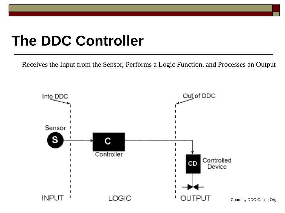
The DDC Controller
Courtesy DDC Online Org
Receives the Input from the Sensor, Performs a Logic Function, and Processes an Output
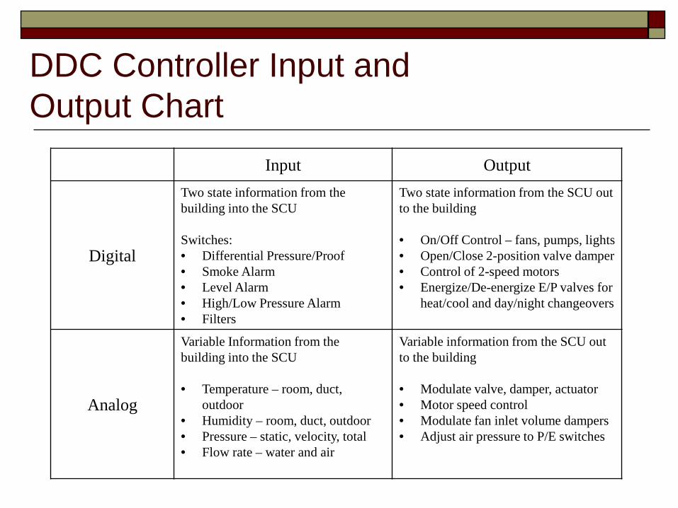
DDC Controller Input and Output Chart
Input Output
Digital
Two state information from the building into the SCU Switches: • Differential Pressure/Proof • Smoke Alarm • Level Alarm • High/Low Pressure Alarm • Filters
Two state information from the SCU out to the building • On/Off Control – fans, pumps, lights • Open/Close 2-position valve damper • Control of 2-speed motors • Energize/De-energize E/P valves for
heat/cool and day/night changeovers
Analog
Variable Information from the building into the SCU • Temperature – room, duct,
outdoor • Humidity – room, duct, outdoor • Pressure – static, velocity, total • Flow rate – water and air
Variable information from the SCU out to the building • Modulate valve, damper, actuator • Motor speed control • Modulate fan inlet volume dampers • Adjust air pressure to P/E switches

Preventive Maintenance Description Comment
Maintenance Frequency Daily Weekly Monthly Annually
Overall visual inspection
Complete overall visual inspection to be sure all equipment is operating and that safety systems are in place.
X
Verify control schedules
Verify in control software that schedules are accurate for season and occupancy. X
Verify setpoints Verify in control software that setpoints are accurate for season and occupancy. X
Time clocks Reset after every power outage. X Check all gauges Check all gauges to make sure readings are
as expected. X
Control tubing (pneumatic system)
Check for proper control and cleanliness. X
Check outside air volumes
Check for proper function. X
Check setpoints Temperatures should not exceed or drop below design limits. X
Check schedules Verify the bottom, surface and water column blow downs are occurring and are effective. X
Check deadbands Assure that all deadbands are accurate and that the only simultaneous heating and cooling is by design.
X
Check sensors Conduct thorough check of all sensors for temperature, pressure, humidity and flow for expected values.
X
Time clocks Check for accuracy and clean. X Back up programs Calibrate sensors Calibrate all sensors for temperature,
pressure, humidity and flow.** X
**Critical sensors should be calibrated seasonally or more often. Critical sensors include Outside Air Sensors, discharge air sensors on large systems, or other sensors that have a large influence on multiple control sequences.

Computerized Control Systems
Hardware
Software
Points
Features and Capabilities
Microprocessor Systems ■ Open source
■ Closed source
■ Wireless

Building Automation System (BAS)
Internet Based?
PC-Based DDC Control System
Graphical User Interface

Courtesy DDC-Online Org
DDC Network Architecture: Large Systems

Courtesy DDC-Online Org
DDC Network Architecture: LAN Configurations

Courtesy DDC-Online Org
DDC Network Architecture: LAN Configurations

Courtesy Alerton Controls
Modern DDC Controls: Four Level Architecture

Courtesy Alerton Controls
Four Level Architecture Level One: “Sensors”

Courtesy Alerton Controls
Four Level Architecture Level Two: “Field Controllers”

Courtesy Alerton Controls
Four Level Architecture Level Three: “Integration”

Courtesy Alerton Controls
Four Level Architecture Level Four: “Management”

Automation systems allow communication with multiple vendors including:
■ HVAC Equipment ■ Fire alarm, security ■ Lighting, fan units ■ PLCs (Programmable Logic Controllers) ■ Boilers and chillers
Communication Standards Software Integration (TCP/IP, BACnet, LON)

Communication Standards

Communication Standards VAV with Terminal Reheat

Energy Conservation Considerations
Optimum Setpoints
Calibration of CO2?
Alarms?
Trend Logging?
System Integration
Preventive Maintenance Checklist

Energy Efficiency Considerations
Are the controls calibrated? ■ How often?
Heating and cooling simultaneously?
Sensing correct medium and location(s)?
Preventive maintenance checklist.

BAS Screen Checks
A methodology for using the GUI as a cost-effective means of keeping track of key indicators of building performance

Graphic User Interface (GUI) as a Diagnostic Tool 1
2
3
4 5 6
7
8

Dampers

Exhaust Air Dampers

GUI Terminal Unit

GUI Terminal Unit

Benefits of the BAS GUI
■ It’s quick! ■ It’s a proactive way
to identify problems and verify proper building HVAC performance.
Image: Williams, Chhen & Gray
Benefits of using the BAS GUI as a maintenance tool:

Verify the GUI for Accuracy
It’s important to first verify the GUI for accuracy. ■ Ensure the system has been
commissioned. ■ Ensure sensors are calibrated. ■ Perform a thorough and documented
point-to-point check if necessary.

System Design & Control Sequences
Gather Building Information. ■ Sequence of operation ■ Controls drawings ■ TAB report ■ Commissioning report ■ System design documents

Trend Data Availability Chilled Water Pump Speed Documenting Actual Operation
■ Ensure trend data will be available for review.

Screen Check Forms
Forms should be tailored to specific types of equipment. ■ Air handlers, chillers, boilers, pumps,
exhaust fans Data to be recorded:
■ Inputs, outputs and setpoints ■ Active alarms ■ Date, time, OSA temperature, user’s
initials.

Screen Check Forms
Examples of Inputs, Outputs and Setpoints: ■ Building static pressure ■ Duct static pressure ■ Outside air damper position ■ Terminal unit minimum and maximum
CFM setpoints ■ Valve positions ■ Fan and pump VFD % speed.
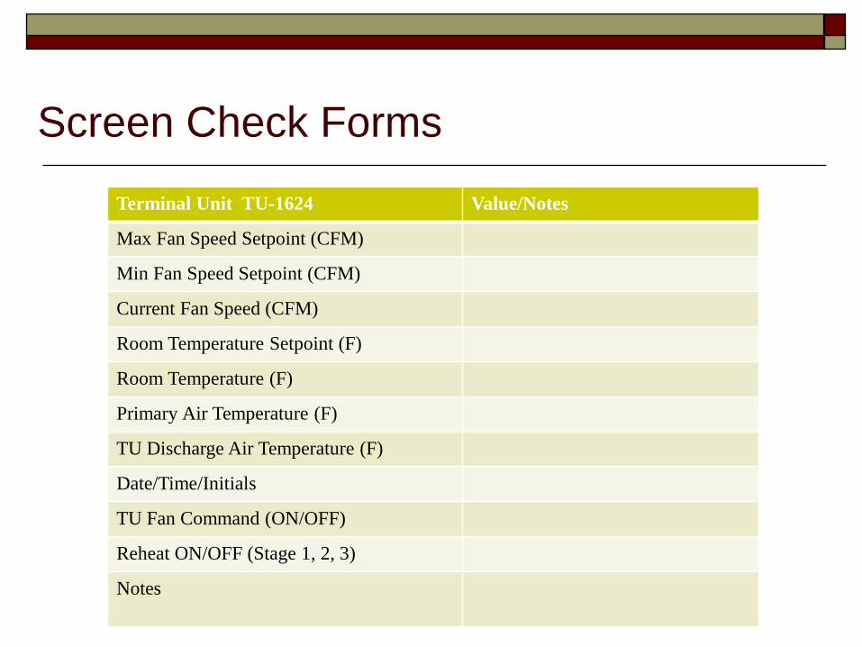
Screen Check Forms
Terminal Unit TU-1624 Value/Notes
Max Fan Speed Setpoint (CFM)
Min Fan Speed Setpoint (CFM)
Current Fan Speed (CFM)
Room Temperature Setpoint (F)
Room Temperature (F)
Primary Air Temperature (F)
TU Discharge Air Temperature (F)
Date/Time/Initials
TU Fan Command (ON/OFF)
Reheat ON/OFF (Stage 1, 2, 3)
Notes

Screen Check Process
Order of checks • Start with the central plant
systems and equipment, including boilers, chillers, cooling towers and pumps. • Complete one system at a
time. • Try to get through all of the
checks in one sitting.
Central plant
One system at a time
One sitting

Screen Check Process Order of Checks ■ For VAV systems, check AHU, then look at zone
temperatures. ■ Spot check several TUs, especially those serving
zones with the greatest deviation from setpoint.
Photo: PECI

Screen Check Process
cogscilibrarian.blogspot.com
• As you record the data, question whether it makes sense.
• Does the data indicate expected and proper operation?
• Do other systems operate in a similar fashion?

Screen Check Process
Frequency ■ Depends on the facility. Complex
systems may require daily or weekly checks.
■ For typical buildings, quarterly or semi-annually to capture seasonal effects.
■ Consider incorporating into your PM schedule.
www.huntscanoes.com

Screen Check Process
Complete the screen check forms in their entirety. ■ Pursue anomalies until you are comfortable systems
are working properly. Document and communicate your findings.
■ Incorporating screen checks into your scheduled PM’s can be an effective way to ensure they are documented.
■ Communicate your findings so the necessary corrective action can be taken when anomalies are noted.
Be persistent!

Trending
Review trend data when more information is needed to support a screen check.
Your ability to trend depends on your BAS capability
What to trend: ■ Outside air temperature ■ Supply air temperature ■ Hydronic temperatures ■ Setpoints, etc.
Image: Penn State University

Trending
Multi-point trends ■ Combine associated data point trends into groups. ■ Include an independent variable in the group to
assist in the analysis (time, OSA temperature).
Proving the trends ■ Collect the data and see if the trends work. ■ Does the data behave as you expect? ■ Customize additional points as necessary.

Energy Efficiency
Common problems: ■ Simultaneous heating & cooling ■ OSA damper position not correct ■ MAT, OSAT, RAT and OSA damper
position not proportionally correct ■ Mechanical cooling on when it’s not
needed.

Minimum OSA Dampers

Minimum OSA Dampers

Energy Efficiency Key Performance Indicators (KPIs) ■ These will present themselves upon
reviewing BAS data and filling out the screen check forms.
■ They can be anomalies in the data or deviations from what you’d expect to see.
■ They may indicate a problem with the system and should be investigated!
■ The following two case studies provide examples.

KPI Case Study: AHU
Case Study #1

KPI Case Study: Chiller
Case Study #2

Controls Service Contract
Annual Training?
Updated Training?
Updated Software?
Alarm Troubleshooting?
What are you getting for your $?

QUESTIONS ?