Embed Size (px)
Citation preview
MANAGING DATA LOCALITY IN FUTURE
MEMORY HIERARCHIES USING A
HARDWARE SOFTWARE
CODESIGN APPROACH
by
Manu Awasthi
A dissertation submitted to the faculty ofThe University of Utah
in partial fulfillment of the requirements for the degree of
Doctor of Philosophy
in
Computer Science
School of Computing
The University of Utah
December 2014

Copyright c© Manu Awasthi 2014
All Rights Reserved

T h e U n i v e r s i t y o f U t a h G r a d u a t e S c h o o l
STATEMENT OF DISSERTATION APPROVAL
The dissertation of Manu Awasthi
has been approved by the following supervisory committee members:
Rajeev Balasubramonian , Chair 03/31/2014
Date Approved
Alan L. Davis , Member 03/31/2014
Date Approved
Ganesh Gopalakrishnan , Member 03/31/2014
Date Approved
John B. Carter , Member
Date Approved
Vijayalakshmi Srinivasan , Member
Date Approved
and by Ross Whitaker , Chair/Dean of
the Department/College/School of School of Computing
and by David B. Kieda, Dean of The Graduate School.
ABSTRACT
In recent years, a number of trends have started to emerge, both in micropro-
cessor and application characteristics. As per Moore’s law, the number of cores on
chip will keep doubling every 18-24 months. International Technology Roadmap for
Semiconductors (ITRS) reports that wires will continue to scale poorly, exacerbating
the cost of on-chip communication. Cores will have to navigate an on-chip network
to access data that may be scattered across many cache banks. The number of
pins on the package, and hence available off-chip bandwidth, will at best increase at
sublinear rate and at worst, stagnate. A number of disruptive memory technologies,
e.g., phase change memory (PCM) have begun to emerge and will be integrated
into the memory hierarchy sooner than later, leading to non-uniform memory access
(NUMA) hierarchies. This will make the cost of accessing main memory even higher.
In previous years, most of the focus has been on deciding the memory hierarchy
level where data must be placed (L1 or L2 caches, main memory, disk, etc.). However,
in modern and future generations, each level is getting bigger and its design is being
subjected to a number of constraints (wire delays, power budget, etc.). It is becoming
very important to make an intelligent decision about where data must be placed within
a level. For example, in a large non-uniform access cache (NUCA), we must figure
out the optimal bank. Similarly, in a multi-dual inline memory module (DIMM) non
uniform memory access (NUMA) main memory, we must figure out the DIMM that
is the optimal home for every data page. Studies have indicated that heterogeneous
main memory hierarchies that incorporate multiple memory technologies are on the
horizon. We must develop solutions for data management that take heterogeneity
into account.
For these memory organizations, we must again identify the appropriate home for
data. In this dissertation, we attempt to verify the following thesis statement: “Can

low-complexity hardware and OS mechanisms manage data placement within each
memory hierarchy level to optimize metrics such as performance and/or throughput?”
In this dissertation we argue for a hardware-software codesign approach to tackle
the above mentioned problems at different levels of the memory hierarchy. The
proposed methods utilize techniques like page coloring and shadow addresses and
are able to handle a large number of problems ranging from managing wire-delays
in large, shared NUCA caches to distributing shared capacity among different cores.
We then examine data-placement issues in NUMA main memory for a many-core
processor with a moderate number of on-chip memory controllers. Using codesign
approaches, we achieve efficient data placement by modifying the operating system’s
(OS) page allocation algorithm for a wide variety of main memory architectures.
iv

To My Mother
In Fond Remembrance of My Father and Grandmothers

CONTENTS
ABSTRACT . . . . . . . . . . . . . . . . . . . . . . . . . . . . . . . . . . . . . . . . . . . . . . . . . . iii
LIST OF FIGURES . . . . . . . . . . . . . . . . . . . . . . . . . . . . . . . . . . . . . . . . . . . . viii
LIST OF TABLES . . . . . . . . . . . . . . . . . . . . . . . . . . . . . . . . . . . . . . . . . . . . . x
ACKNOWLEDGMENTS . . . . . . . . . . . . . . . . . . . . . . . . . . . . . . . . . . . . . . . xi
CHAPTERS
1. INTRODUCTION . . . . . . . . . . . . . . . . . . . . . . . . . . . . . . . . . . . . . . . . . 1
1.1 Last Level Caches . . . . . . . . . . . . . . . . . . . . . . . . . . . . . . . . . . . . . . . . 11.2 Evolution of DRAM and Loss of Locality . . . . . . . . . . . . . . . . . . . . . . 31.3 Disruptive Memory Technologies . . . . . . . . . . . . . . . . . . . . . . . . . . . . . 51.4 Leveraging Hardware-Software Codesign . . . . . . . . . . . . . . . . . . . . . . . 61.5 Thesis Statement . . . . . . . . . . . . . . . . . . . . . . . . . . . . . . . . . . . . . . . . . 71.6 Dissertation Organization . . . . . . . . . . . . . . . . . . . . . . . . . . . . . . . . . . 7
2. MANAGING DATA LOCALITY IN LARGE LEVEL CACHES 9
2.1 Background . . . . . . . . . . . . . . . . . . . . . . . . . . . . . . . . . . . . . . . . . . . . . 92.2 Proposed Mechanisms . . . . . . . . . . . . . . . . . . . . . . . . . . . . . . . . . . . . . 11
2.2.1 Page Recoloring . . . . . . . . . . . . . . . . . . . . . . . . . . . . . . . . . . . . . . 122.2.1.1 Baseline Design . . . . . . . . . . . . . . . . . . . . . . . . . . . . . . . . . . 122.2.1.2 Page Renaming . . . . . . . . . . . . . . . . . . . . . . . . . . . . . . . . . . 122.2.1.3 Unique Addresses . . . . . . . . . . . . . . . . . . . . . . . . . . . . . . . . 132.2.1.4 TLB Modifications . . . . . . . . . . . . . . . . . . . . . . . . . . . . . . . 142.2.1.5 Off-Chip Access . . . . . . . . . . . . . . . . . . . . . . . . . . . . . . . . . . 142.2.1.6 Translation Table (TT) . . . . . . . . . . . . . . . . . . . . . . . . . . . . 142.2.1.7 Cache Flushes . . . . . . . . . . . . . . . . . . . . . . . . . . . . . . . . . . . 152.2.1.8 Cache Tags and Indexing . . . . . . . . . . . . . . . . . . . . . . . . . . 162.2.1.9 Effects on Coherence Protocol . . . . . . . . . . . . . . . . . . . . . . . 16
2.2.2 Managing Capacity Allocation and Sharing . . . . . . . . . . . . . . . . 172.2.2.1 Capacity Allocation Across Cores . . . . . . . . . . . . . . . . . . . . 182.2.2.2 Migration for Shared Pages . . . . . . . . . . . . . . . . . . . . . . . . . 20
2.3 Results . . . . . . . . . . . . . . . . . . . . . . . . . . . . . . . . . . . . . . . . . . . . . . . . . 212.3.1 Methodology . . . . . . . . . . . . . . . . . . . . . . . . . . . . . . . . . . . . . . . . 212.3.2 Baseline Configurations . . . . . . . . . . . . . . . . . . . . . . . . . . . . . . . . 232.3.3 Multiprogrammed Results . . . . . . . . . . . . . . . . . . . . . . . . . . . . . . 25
2.3.3.1 Multicore Workloads . . . . . . . . . . . . . . . . . . . . . . . . . . . . . . 262.3.4 Results for Multithreaded Workloads . . . . . . . . . . . . . . . . . . . . . 29
2.4 Summary and Discussion . . . . . . . . . . . . . . . . . . . . . . . . . . . . . . . . . . . 34

3. HANDLING LOCALITY CHALLENGES IN MAIN MEMORY 37
3.1 Introduction . . . . . . . . . . . . . . . . . . . . . . . . . . . . . . . . . . . . . . . . . . . . . 383.2 Background and Motivational Results . . . . . . . . . . . . . . . . . . . . . . . . . 41
3.2.1 DRAM Basics . . . . . . . . . . . . . . . . . . . . . . . . . . . . . . . . . . . . . . . 413.2.2 Current/Future Trends in MC Design . . . . . . . . . . . . . . . . . . . . . 423.2.3 OS Support for DRAM/NUMA Systems . . . . . . . . . . . . . . . . . . . 453.2.4 Motivational Data . . . . . . . . . . . . . . . . . . . . . . . . . . . . . . . . . . . . 46
3.3 Proposed Mechanisms . . . . . . . . . . . . . . . . . . . . . . . . . . . . . . . . . . . . . 483.3.1 Adaptive First-Touch (AFT) Page Placement Policy . . . . . . . . . 503.3.2 Dynamic Page Migration Policy . . . . . . . . . . . . . . . . . . . . . . . . . 513.3.3 Heterogeneous Memory Hierarchy . . . . . . . . . . . . . . . . . . . . . . . . 533.3.4 Overheads of Estimation and Migration . . . . . . . . . . . . . . . . . . . 55
3.4 Results . . . . . . . . . . . . . . . . . . . . . . . . . . . . . . . . . . . . . . . . . . . . . . . . . 563.4.1 Metrics for Comparison . . . . . . . . . . . . . . . . . . . . . . . . . . . . . . . . 583.4.2 Multiple Memory Controllers — Homogeneous
DRAM Hierarchy . . . . . . . . . . . . . . . . . . . . . . . . . . . . . . . . . . . . . 593.4.2.1 Adaptive First-Touch and Dynamic Migration Policies —
Homogeneous Hierarchy . . . . . . . . . . . . . . . . . . . . . . . . . . . 613.4.2.2 Effects of TLB Shootdowns . . . . . . . . . . . . . . . . . . . . . . . . . 63
3.4.3 Sensitivity Analysis . . . . . . . . . . . . . . . . . . . . . . . . . . . . . . . . . . . 633.4.3.1 Results for Multisocket Configurations . . . . . . . . . . . . . . . . 633.4.3.2 Effects of Individual Terms in Cost Functions . . . . . . . . . . . 653.4.3.3 Recipient MC Decision for Dynamic Migration Policy . . . . 66
3.4.4 Multiple Memory Controllers — HeterogeneousHierarchy . . . . . . . . . . . . . . . . . . . . . . . . . . . . . . . . . . . . . . . . . . . 69
3.4.5 Adaptive First-Touch and Dynamic Migration Policies –Heterogeneous Hierarchy . . . . . . . . . . . . . . . . . . . . . . . . . . . . . . . 70
3.4.6 Sensitivity Analysis and Discussion — HeterogeneousHierarchy . . . . . . . . . . . . . . . . . . . . . . . . . . . . . . . . . . . . . . . . . . . 72
3.4.6.1 Sensitivity to Physical Placement of MCs . . . . . . . . . . . . . . 723.4.6.2 Cost of TLB Shootdowns . . . . . . . . . . . . . . . . . . . . . . . . . . 72
3.5 Related Work . . . . . . . . . . . . . . . . . . . . . . . . . . . . . . . . . . . . . . . . . . . . 723.5.1 Memory Controllers . . . . . . . . . . . . . . . . . . . . . . . . . . . . . . . . . . . 723.5.2 Memory Controllers and Page Allocation . . . . . . . . . . . . . . . . . . 743.5.3 Page Allocation . . . . . . . . . . . . . . . . . . . . . . . . . . . . . . . . . . . . . . 743.5.4 Task Scheduling . . . . . . . . . . . . . . . . . . . . . . . . . . . . . . . . . . . . . . 74
3.6 Summary . . . . . . . . . . . . . . . . . . . . . . . . . . . . . . . . . . . . . . . . . . . . . . . 75
4. CONCLUSIONS . . . . . . . . . . . . . . . . . . . . . . . . . . . . . . . . . . . . . . . . . . . 76
4.1 Future Work . . . . . . . . . . . . . . . . . . . . . . . . . . . . . . . . . . . . . . . . . . . . 774.1.1 Main Memory Subsystem Challenges . . . . . . . . . . . . . . . . . . . . . 78
4.1.1.1 Scheduling Memory Requests . . . . . . . . . . . . . . . . . . . . . . . 794.1.2 Storage Class Memory Hierarchies . . . . . . . . . . . . . . . . . . . . . . . . 804.1.3 Data Management in Emerging Memory Technologies . . . . . . . . 80
REFERENCES . . . . . . . . . . . . . . . . . . . . . . . . . . . . . . . . . . . . . . . . . . . . . . . . 81
vii

LIST OF FIGURES
2.1 Address structure and address modifications required to access migratedpages. . . . . . . . . . . . . . . . . . . . . . . . . . . . . . . . . . . . . . . . . . . . . . . . . . . . 13
2.2 Arrangement of processors, NUCA cache banks, and the on-chipinterconnect. . . . . . . . . . . . . . . . . . . . . . . . . . . . . . . . . . . . . . . . . . . . . . . 18
2.3 Experiments to determine workloads — IPC improvements withincreasing L2 capacities. . . . . . . . . . . . . . . . . . . . . . . . . . . . . . . . . . . . . . 24
2.4 Experiments to determine workloads — Relative IPC improvements forsingle core with color stealing. . . . . . . . . . . . . . . . . . . . . . . . . . . . . . . . . 25
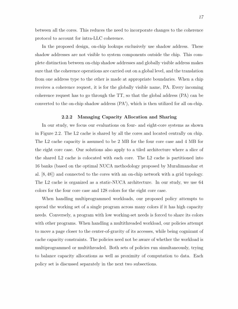
2.5 Weighted throughput of system with two acceptors and two donors. . . . 28
2.6 Weighted throughput of system with three acceptors and one donor. . . 29
2.7 Normalized system throughput as compared to BASE-PRIVATE —Weighted throughput of system with four cores and four acceptors. . . . 30
2.8 Normalized system throughput as compared to BASE-PRIVATE —Weighted throughput for eight core workloads. . . . . . . . . . . . . . . . . . . . 31
2.9 Percentage improvement in throughput. . . . . . . . . . . . . . . . . . . . . . . . . . 32
2.10 Improvement in throughput overlaid with percentage accesses to movedpages. . . . . . . . . . . . . . . . . . . . . . . . . . . . . . . . . . . . . . . . . . . . . . . . . . . . 33
2.11 Percentage change in network contention due to proposed schemes. . . . 34
2.12 Number of cache lines flushed due to migration of RW-shared pages. . . 35
2.13 Throughput improvement for eight-core CMP. . . . . . . . . . . . . . . . . . . . . 36
3.1 Platforms with multiple memory controllers. (A) Logical organizationof a multisocket Nehalem. (B) Assumed sixteen-core four-MC model. . 43
3.2 Relative queuing delays for 1 and 16 threads, single MC, 16 cores. . . . . 47
3.3 Row-buffer hit rates, dual-socket, quad-core Opteron. . . . . . . . . . . . . . 48
3.4 Impact of multiple memory controllers, homogeneous hierarchy— number of controllers versus throughput. . . . . . . . . . . . . . . . . . . . . . 59
3.5 Impact of multiple memory controllers, homogeneous hierarchy— number of controllers versus average queuing delays. . . . . . . . . . . . . 60
3.6 Row-buffer hit rate comparison for adaptive first-touch and dynamicmigration policies versus baseline for homogeneous hierarchy. . . . . . . . . 62
3.7 Relative throughput performance for adaptive first-touch and dynamicmigration policies versus baseline in homogeneous hierarchy. . . . . . . . . . 63
3.8 DRAM access latency breakdown (CPU cycles) for homogeneoushierarchy. . . . . . . . . . . . . . . . . . . . . . . . . . . . . . . . . . . . . . . . . . . . . . . . . 64
3.9 Throughput sensitivity to physical placement of MCs, dynamic pagemigration policy for homogeneous hierarchy. . . . . . . . . . . . . . . . . . . . . . 66
3.10 Impact of individual terms in the cost function, with one term used formaking decisions. . . . . . . . . . . . . . . . . . . . . . . . . . . . . . . . . . . . . . . . . . . 67
3.11 Impact of individual terms in the cost function, with two terms used formaking decisions. . . . . . . . . . . . . . . . . . . . . . . . . . . . . . . . . . . . . . . . . . . 68
3.12 Factors for deciding recipient MCs. DMP-N RB% decides to migratepages if row-buffer hit rates decrease by N% from the previous epoch.DMP-N Cycle Q delay does the same if queuing delay increases by Ncycles from the previous epoch. . . . . . . . . . . . . . . . . . . . . . . . . . . . . . . . 69
3.13 Impact of proposed policies in heterogeneous memory hierarchy (NDRAM - P Fast). . . . . . . . . . . . . . . . . . . . . . . . . . . . . . . . . . . . . . . . . . . 70
3.14 Impact of proposed policies in heterogeneous memory hierarchy (NDRAM - P PCM). . . . . . . . . . . . . . . . . . . . . . . . . . . . . . . . . . . . . . . . . . 71
ix

LIST OF TABLES
2.1 Simics simulator parameters. . . . . . . . . . . . . . . . . . . . . . . . . . . . . . . . . . 22
2.2 Workload characteristics. ∗ - SPECCPU2006, • - BioBench, ⋆ - PARSEC. 23
2.3 Behavior of PROPOSED-COLOR-STEAL. . . . . . . . . . . . . . . . . . . . . . . 26
2.4 Workload mixes for four and eight cores. Each workload will be referredto by its superscript name. . . . . . . . . . . . . . . . . . . . . . . . . . . . . . . . . . . . 27
2.5 SPLASH-2 and PARSEC programs with their inputs and percentage ofRW-shared pages. . . . . . . . . . . . . . . . . . . . . . . . . . . . . . . . . . . . . . . . . . . 31
3.1 DRAM timing parameters [1, 2]. . . . . . . . . . . . . . . . . . . . . . . . . . . . . . . 54
3.2 Simulator parameters. . . . . . . . . . . . . . . . . . . . . . . . . . . . . . . . . . . . . . . 57
3.3 Dynamic page migration overhead characteristics. . . . . . . . . . . . . . . . . . 65

ACKNOWLEDGMENTS
A lot of time and effort goes into a dissertation, the least of which actually deals
with writing it. It marks the culmination of a number of years’ worth of effort into
one document, which, if signed by a dissertation committee, validates so many years
of hard work, tears and sweat that were shed along the way to get there. The group
of people that you encounter along the way can make or break the experience. And I
was lucky enough to have met a group of people that made this journey an extremely
enjoyable one.
First and foremost, I’d like to profusely thank my advisor, Rajeev, for supporting
me throughout my time in graduate school. In the summer of 2006, he took a doe-
eyed, second year graduate student under his wing and showed him the ropes of
academic research. Rajeev, in addition to being an amazing human being, is by the
far the best adviser that anyone can ever hope to have. Throughout the past six
years, at different times, he has served as a mentor, a dissertation adviser and a
friend (whom you can count on for free food around paper deadlines). There is no
way that I would have been able to complete this dissertation without his support.
I would like to sincerely thank my dissertation committee members, who have
been excellent mentors and research collaborators. Thanks to them, I have been
introduced to some of the most important concepts in computer science in the most
fascinating way possible. John Carter taught the graduate level courses on operating
and distributed systems. I don’t think one can ask for a better teacher to get insight
into computer systems from a system software’s perspective. Al Davis initiated us
in the black art of DRAM design and optimization in the best way possible. Ganesh
Goplakrishnan taught the course on formal methods, which provided an excellent
insight on the problem of writing correct parallel programs. Viji Srinivasan brought
in the industrial perspective for nonvolatile memory systems, and made sure we were

working on solving real problems. I cannot thank them enough for all their help over
the years.
A lot of people, both in Utah and elsewhere, helped me to get to the point where I
am today. They might not have directly contributed to the writing of this dissertation,
but they did make sure that I was able to keep my sanity long enough to complete this
document. Special thanks are due to Subodh and Amlan, who proved to be excellent
roommates and even better partners in crime during my stay in Salt Lake City. My lab
mates at the Utah Arch Lab have been amazing friends and collaborators. Niladrish,
Kshitij, Dave, Aniruddha, Seth, Vivek, Niti, Karthik, Vamshi, Byong, and Naveen
made the long hours spent at school enjoyable.
I would be amiss if I failed to mention Karen Feinauer and Ann Carlstrom for their
help with the administrative process. Karen made our lives extremely uncomplicated
by shielding us from the barrage of paperwork. I really cannot thank her enough for
that.
Last, but not the least, special thanks are due to my family, without whose
encouragement and constant support none of this would have been possible. From
a very early age, my mother, Pratima, and my grandparents, Indu and Om Shankar
Misra, instilled in me the importance of education in one’s life. My mother supported
my decision to attend graduate school without so much as batting an eyelid. This
document would never have seen the light of day if it was not for her. My sister,
Vasundhara, and cousins, Priyam and Anant, were always there to lend an ear
whenever I needed to vent my exasperations. My aunts, Lakshmi and Anupama,
and my uncle, Salil, were always there to provide support and encouragement along
the way. The final version of this dissertation would not have been completed without
the constant encouragement of Priyamvada.
xii

CHAPTER 1
INTRODUCTION
Memory hierarchies are undergoing a significant change in modern times. This
chapter highlights some of the emerging trends in memory technologies, starting at
the last level caches all the way up to main memory. Each section will showcase how
these trends and technologies contribute to decreasing locality and increasing access
times. We then make a case for a hardware-software codesign approach as the most
viable method for increasing locality and managing data at all levels, with minimal
overheads.
1.1 Last Level Caches
Future high-performance processors will implement hundreds of processing cores.
To handle the data requirements of these many cores, processors will provide many
megabytes of shared L2 or L3 caches. These large caches will likely be heavily banked
and distributed across the chip. For example, each core may be associated with one
private bank of the last level cache (LLC), thus forming a tiled architecture [3, 4]. In
other cases of such tiled architectures, the LLC might be shared, but each tile might
have one bank of the multibanked last level cache associated with it.
An on-chip network connects the many cores and cache banks (or tiles) [4]. Such
caches will conform to a non-uniform cache access (NUCA) architecture [5] as the
latency of each access will be a function of the distance traveled on the on-chip
network. The design of large last-level caches continues to remain a challenging
problem for the following reasons: (i) long wires and routers in the on-chip network
have to be traversed to access cached data. The on-chip network can contribute up
to 36% of total chip power [6, 7] and incur delays of nearly a hundred cycles [8]. It is

2
therefore critical for performance and power that a core’s/thread’s 1 data be placed
in a physically proximal cache bank. (ii) On-chip cache space will now be shared
by multiple threads and multiple applications, leading to possibly high (destructive)
interference. Poor allocation of cache space among threads can lead to suboptimal
cache hit rates and poor throughput.
Both of the above problems have been actively studied in recent years. To improve
the proximity of data and computation, dynamic-NUCA (D-NUCA) policies have
been proposed [5, 9–15]. In D-NUCA mechanisms, the ways of a set are distributed
among various banks and a data block (cache line) is allowed to migrate from one
way in a bank to another way in a different bank. The intuition behind this approach
is that such a migration will hopefully result in bringing the cache line closer to the
core accessing this data block. While it seems beneficial, the problem with D-NUCA
approaches is the need for a complex search mechanism. Since the block could reside
in one of the many possible ways, the banks (or a complex tag structure) must be
systematically searched before a cache hit/miss can be declared. As the number of
cores is scaled up, requiring an increased cache capacity, the number of ways will
also have to be scaled up, further increasing the power and complexity of the search
mechanism.
The problem of cache space allocation among threads has also been addressed by
recent papers [16–19]. Many of these papers attempt to distribute ways of a cache
among threads by estimating the marginal utility of an additional way for each thread.
Again, this way-centric approach is not scalable as a many-core architecture will
have to support a highly set-associative cache and its corresponding power overheads.
These way-partitioning approaches also assume uniform cache architectures (UCA)
and are hence only applicable for medium-sized caches.
Recent work by Cho and Jin [20] puts forth an approach that is inherently scalable,
applicable to NUCA architectures, and amenable to several optimizations. Their work
adopts a static-NUCA architecture where all ways of a cache set are localized to a
single bank. A given address thus maps to a unique bank and a complex search
1Cores and threads will be used interchangeably throughout this document, unless specifiedotherwise.

3
mechanism is avoided. The placement of a data block within the cache is determined
by the physical memory address assigned to that block. That work therefore proposes
operating system (OS) based page coloring as the key mechanism to dictate placement
of data blocks within the cache. Cho and Jin focus on the problem of capacity
allocation among cores and show that intelligent page coloring can allow a core to
place its data in neighboring banks if its own bank is heavily pressured. This software
control of cache block placement has also been explored in other recent papers [21, 22].
This page-coloring approach attempts to split sets (not ways) among cores. It is
therefore more scalable and applies seamlessly to static-NUCA designs.
All this work still does not bridge the gap of devising low-overhead policies for
achieving the benefits of D-NUCA while retaining the simplicity of a static-NUCA
architecture and avoiding complex searches. Several issues still need to be addressed
with the page coloring approach described in recent papers [20, 21, 23]: (i) a page is
appropriately colored on first-touch, but this may not be reflective of behavior over
many phases of a long-running application, especially if threads/programs migrate
between cores or if the page is subsequently shared by many cores. (ii) If we do
decide to migrate pages in response to changing application behavior, how can efficient
policies and mechanisms be designed, while eliminating the high cost of dynamic
random access memory (DRAM) page copies?
1.2 Evolution of DRAM and Loss of Locality
Modern microprocessors increasingly integrate the memory controller (MC) on-
chip in order to reduce main memory access latency. Memory pressure will increase
with core-counts per socket and a single MC will quickly become a bottleneck. In order
to avoid this problem, modern multicore processor chips (chip multiprocessors, CMPs)
have begun to integrate multiple MCs and multiple memory channels per socket [24–
26]. Similarly, multisocket motherboards provide connections to multiple MCs via
off-chip interconnects such as Advanced Micro Device’s HyperTransportTM(HT) and
Intel’s Quick Path InterconnectTM(QPI). In both situations, a core may access any
DRAM location by routing its request to the appropriate MC. Multicore access to a
large physical memory space partitioned over multiple MCs is likely to continue and
exploiting MC locality will be critical to aggregate system performance.

4
In a Nehalem-like architecture where there are multiple memory controllers, each
memory controller has a dedicated channel to its own dual in-line memory module
(DIMM) package. Each DIMM package handles a subset of the physical address space
(just as each bank within a DIMM handles a subset of the physical address space
assigned to that DIMM). There has been little work on devising novel mechanisms to
stripe data across different DIMMs or banks to promote either DIMM- or bank-level
parallelism (a paper by Zhang et al. [27] employs a hardware mechanism within
the memory controller to promote bank-level parallelism). It is expected that in a
Nehalem-like multisocket architecture where local memory accesses are 1.5x faster
than nonlocal memory accesses, the OS would allocate page requests from a core to
a region of physical memory that is local to that core (socket).
Recent efforts [26, 28–30] have incorporated multiple MCs in their designs, but
there is little evidence on how data placement should be managed and how this
placement policy will affect main memory access latencies. We propose to address
this problem by noting that simply allocating an application thread’s data to the
closest MC may not be optimal since it does not take into account queuing delays,
row-buffer conflicts, etc. In particular, we believe that striping data (physical pages)
across multiple MCs should be based on placement strategies which incorporate: (i)
the communication distance and latency between the core and the MC, (ii) queuing
delay at the MC, and (iii) DRAM access latency which is heavily influenced by row-
buffer hit rates. We hypothesize that improper management of these factors can
cause a significant degradation of performance and propose policies to overcome these
challenges.
Future multicores will execute a multitude of applications – highly multithreaded
server workloads, a diverse combination of single threaded workloads or opt for server
consolidation by running multiple virtual machines (VMs) on a single chip. Such
a workload, or a combination of dissimilar workloads will result in intermingling of
memory requests from various cores at the MC. This will lead to loss of spatiotemporal
locality in the memory access stream, making it appear extremely randomized to the
MC. Loss in locality will in turn lead to increased contribution of system overheads
like queuing delays to overall main memory access latency. With the total physical

5
address space distributed across multiple on-chip memory controllers, this problem
will be exacerbated if the memory allocation for a thread is done without taking into
consideration the aforementioned factors.
To date, no work has focused on studying the role of and opportunities made
possible by data placement and controller scheduling policies in the context of multiple
on-chip memory controllers. Going one level further, multiple processors (each with
multiple MCs) will be incorporated on a single board across multiple sockets. These
sockets will then be connected by a proprietary network, while maintaining a shared,
flat address space at the same time. This will result in even more complicated and
nested on-board NUMA hierarchies. For such architectures, it becomes imperative
to make the system software cognizant of the inherent difference in memory access
times, so that near-optimal data placement decisions can be made.
1.3 Disruptive Memory Technologies
Nonvolatile memories (NVRAMs) are emerging as a popular alternative to bridg-
ing the large latency gap between main memory and disk, and upon maturing, a
possible alternative to main memory itself. A large amount of current research is
being done to overcome the initial challenges for most of the technologies. However,
the two most mature of these are phase change memory (PCM) and spin torque
transfer memory (STT-RAM).
PCM is considered a front-runner among emerging NVM technologies. The ben-
efits of PCM include small per-bit cost, longer data retention (> 10 years), high
endurance ( > 1013 write-erase-cycles), good scalability, low voltage operation, low
standby current (< 1µA), high switching speeds and nondestructive reads [31, 32].
All of these make PCRAM an active competitor to DRAM based main memory.
Recently, PCM parts have been made available on a commercial basis [33]. For all its
potential advantages, PCM still suffers from a high difference between read and write
access latencies. Moreover, unlike DRAM, each PCM cell has limited write cycles,
which requires wear-leveling measures to be incorporated in the devices.
With these advantages, there is a strong possibility that PCM will be a strong
contender to replace DRAM as main memory, especially with issues of scalability of

6
DRAM devices beyond 40 nm [34, 35] 2. Depending on a number of factors, these
developments will lead to heterogeneousmain memory architectures [33]. For example,
a number of recent studies [2, 33] propose replacing PCM as main memory, while
maintaining a DRAM cache to store recently used data to keep access latencies in
check.
With multiple MCs being integrated on-chip, we can imagine a scenario where
each of the MCs could potentially be controlling different kinds of memory technolo-
gies. For example, a multicore chip may have four onchip memory controllers, with
each of these controllers managing double data rate (DDRx), fully buffered DIMM
(FB-DIMM) or PCM devices. These memory hierarchies will require explicit data
management because of the varying characteristics of the technologies involved.
1.4 Leveraging Hardware-Software Codesign
The developments described in previous sections highlight four major issues: (i)
caches, especially LLCs will grow in size and offer nonuniform access latencies, ap-
plications will continue to contend for this space so there is an immediate need to
divide this cache space between competing cores at runtime. (ii) Locality in the main
memory access stream is diminishing because of interleaving of memory accesses from
different cores making it appear more and more randomized. (iii) MCs are being
integrated on chip, while maintaining a shared, flat address space at the same time;
interconnect and queuing delays will lead to nonuniform access for different parts of
the shared address space. (iv) Emerging memory technologies like PCM are touted
to replace DRAM as main memory, or work in conjunction with existing technologies
leading to the creation of heterogeneous hierarchies.
These developments will give rise to a number of memory hierarchies which will
vary a lot across vendors. As we pointed out before, trying to manage locality
by using hardware-only mechanisms will lead to unacceptably large overheads. On
the other hand, software-only mechanisms would involve nontrivial changes to the
system software. At the very least, this would require substantial changes to the
page allocation mechanisms in the kernel to make it cognizant of the underlying
2There are varying opinions about the exact nm value, but 2009 semiconductor roadmap editionindicates that there are no known manufacturable solutions beyond 40 nm.

7
architecture, and at worst it might require a complete redesign of the entire software
stack. Both these approaches by themselves cannot provide a sustainable and scalable
solution to the problem.
To this end, in this dissertation, we propose using the middle path – we propose
a hardware software codesign approach that can combine the favorable properties of
both approaches. Using this approach, we propose to split the functionality to manage
data and increase locality between the hardware and (system) software. Various
statistics are kept track of in the hardware, and every epoch, the system software
makes a policy decision about increasing locality, or dividing available resources
amongst various cores. Operations that are on the critical path of memory accesses
are implemented in hardware, while infrequently occurring decision making operations
are relegated to the software.
1.5 Thesis Statement
Memory technologies have undergone many advancements in recent years. Mem-
ory hierarchies are becoming bigger and offering nonuniform access to different parts
of a single level of the hierarchy. They are also being shared by many applications.
In this dissertation, we argue that resources and data placement must be managed
intelligently to optimize various system metrics. Our hypothesis is that such manage-
ment is best done with a hardware-software codesign approach. Using this approach,
hardware keeps track of runtime events via application monitoring, while the system
software does the relatively infrequent task of decision making.
1.6 Dissertation Organization
This dissertation is organized as follows. We provide background information,
present existing state-of-the-art techniques and motivate the need for managing lo-
cality in future memory hierarchies in Chapter 1. Each subsequent chapter deals
with one distinct level of the memory hierarchy, starting at the level of last level
caches. We propose codesign approaches starting at the shared, multi-megabyte last
level caches in Chapter 2. Then, in Chapter 3 we describe mechanisms to manage
locality in future NUMA homogeneous and heterogeneous main memory hierarchies.

8
Additional details and related work are provided with each chapter. Finally, we
conclude in Chapter 4 where we also identify some areas for future work.
CHAPTER 2
MANAGING DATA LOCALITY IN LARGE
LEVEL CACHES
For one of the main proposals of this dissertation, we start by utilizing the codesign
approach to manage data locality in last level caches (LLCs). As mentioned in
Chapter 1, shared LLCs in multicore architectures suffer from a number of issues,
including increased wire delays for cache accesses and contention between cores for
cache capacity.
In this Chapter, we will present mechanisms that leverage page-coloring to propose
solutions to aforementioned problems. We first propose mechanisms to decrease wire
delays by remapping data to sets and/or banks closer to the cores. Next, we propose
novel solutions to manage LLC capacity between different cores at runtime using
a variation of the page-coloring approach. As a final optimization, we also present
methods to bring shared data to the center of gravity of the cores accessing it, thereby
reducing the average time to access the shared data across all cores.
2.1 Background
Traditionally, the operating system’s (OS) memory management unit (MMU)
carries out the virtual to physical address mappings. Since most of MMUs are
oblivious of the underlying cache architectures, the OS inadvertently decides where
a core’s data resides in the physically indexed cache. Also, since most LLCs are
physically indexed and physically tagged, the virtual to physical address mapping
assigned to data by the OS decides the physical location of said data in the LLC. If the
OS can be made aware of the underlying cache architecture, it can make intelligent
decisions about assigning physical pages to threads and help in increasing locality
within caches. However, since there are potentially hundreds of architectures on
the market today, it would be extremely difficult to include information about all

10
possible permutations and combinations of the architecture within the OS. Moreover,
it would require nontrivial changes to OS page allocation algorithms, which would be
a tremendous software overhead.
Page coloring is an effort to bridge this gap, and can be implemented in hardware,
to a certain extent. In the hardware-centric approach, it will involve adding another
level of indirection on-chip so that data can be migrated on-chip, with minimal
system software interference. Page coloring for data placement within the cache
was extensively studied by Kessler and Hill [36]. Several commercial systems have
implemented page migration for distributed memory systems, most notably SGI’s
implementation of page-migration mechanisms in their IRIX operating system [37].
LaRowe et al. [38–40] devised OS support mechanisms to allow page placement
policies in NUMA systems. Another body of work [41, 42] explored the problem
from a multiprocessor compute server perspective and dealt with similar mechanisms
as LaRowe et al. to schedule and migrate pages to improve data locality in cc-NUMA
machines. The basic ideas in these papers also bear some similarities to simple cache
only memory architecture (S-COMA) [43] and its derivatives (R-NUMA [44] and
Wildfire [45]). However, note that there are no replicated pages within our L2 cache
(and hence no intra-L2 cache coherence). Key differences between our work and
the cc-NUMA work is our use of shadow addresses to rename pages elegantly, the
need to be cognizant of bank capacities, and the focus on space allocation among
competing threads. There are also several differences between the platforms of the
1990s and multicores of the future (sizes of caches, latencies, power constraints,
on-chip bandwidth, transistors for hardware mechanisms, etc.), due to which a direct
port of previously proposed solutions is not feasible.
For the purposes of the problem at hand, the most related body of work is that
by Cho and Jin [20], where they propose the use of page coloring as a means to
dictate block placement in a static-NUCA architecture. That work shows results for
a multiprogrammed workload and evaluates the effect of allowing a single program
to borrow cache space from its neighboring cores if its own cache bank is pressured.
Cho and Jin employ static thresholds to determine the fraction of the working set size
that spills into neighboring cores. They also color a page once at first-touch and do

11
not attempt page migration (the copying of pages in DRAM physical memory), which
is clearly an expensive operation. They also do not attempt intelligent placement of
pages within the banks shared by a single multithreaded application. Concurrent to
our work, Chaudhuri [46] also evaluates page-grain movement of pages in a NUCA
cache. That work advocates that page granularity is superior to block granularity
because of high locality in most applications. Among other things, our work differs in
the mechanism for page migration and in our additional focus on capacity allocation
among threads. The contributions of this chapter can be briefly summarized as
follows.
• We introduce a hardware-centric mechanism that is based on shadow addresses
and a level of indirection within the L2 cache to allow pages to migrate at low
overheads within a static-NUCA cache.
• The presence of a low-overhead page migration mechanism allows us to devise
dynamic OS policies for page movement. Pages are not merely colored at
first-touch and our schemes can adapt to varying program behavior or even
process/thread migration.
• The proposed novel dynamic policies can allocate cache space at a fine granu-
larity and move shared pages to the center of gravity of its accesses, while being
cognizant of cache bank pressure, distances (i.e., wire delays) in a NUCA cache,
and time-varying requirements of programs. The policies do not rely on a-priori
knowledge of the program, but rely on hardware counters.
• The proposed design has low complexity, high performance, low power, and
policy flexibility. It represents the state-of-the-art in large shared cache design,
providing the desirable features of static-NUCA (simple data look-up), dynamic-
NUCA (proximity of data and computation), set-partitioning (high scalability
and adaptability to NUCA), hardware-controlled page movement/placement
(low-cost migration and fine-grained allocation of space among threads), and
OS policies (flexibility).
2.2 Proposed Mechanisms
We first describe the mechanisms required to support efficient page migration.
We avoid DRAM page copies and simply change the physical address that is used

12
internally within the processor for that page. We then discuss the policies to imple-
ment capacity allocation and sharing. The discussion below pertains to a multicore
system where each core has private level one data and instruction (L1-D/I) caches
and a large shared level two (L2) is shared among all the cores as the LLC. Each
L2 block maintains a directory to keep track of L1 cached copies and implement a
modified/exclusive/shared/invalid (MESI) coherence protocol.
2.2.1 Page Recoloring
2.2.1.1 Baseline Design
In a conventional cache hierarchy, the CPU provides a virtual address that is used
to index into the L1 cache and translation lookaside buffer (TLB). The TLB converts
the virtual page number (VPN) to a physical page number (PPN). Most L1 caches are
virtually indexed and physically tagged and hence the output of the TLB is required
before performing the tag comparison.
The top of Figure 2.1 shows the structure of a typical physical address. The
intersection of the physical page number bits and the cache index bits are often
referred to as the page color bits. These are the bits that the OS has control over,
thereby also exercising control over where the block gets placed in cache. Without
loss of generality, we focus on a subset of these bits that will be modified by our
mechanisms to alter where the page gets placed in the L2 cache. This subset of bits
is referred to as the original page color (OPC) bits in Figure 2.1.
Modern hardware usually assumes 64-bit wide memory addresses, but in practice
only employs a subset of these 64 bits. For example, SUN’s UltraSPARC-III architec-
ture [47] has a 64-bit wide memory addresses but uses only 44 and 41 bits for virtual
and physical addresses, respectively. The most significant 23 bits that are unused are
referred to as shadow bits (SB). Since these bits are unused throughout the system,
they can be used for internal manipulations within the processor.
2.2.1.2 Page Renaming
The goal of our page migration mechanism is to preserve the original location
of the page in physical memory, but refer to it by a new name within the processor.
When the virtual address (VA) indexes into the TLB, instead of producing the original

13
Shadow�bits�(SB) Physical�Tag�(PT)Original�Page�
Color�(OPC)Page�Offset�(PO)
L2�index�bits
L1��and�L2�CacheOffrchip
(Main�Memory)
VPN PPN New
Page
Color
Physical�page�number
TLB
Virtual�Address
SB PT OPC PO + Æ PTOPC PONPC
Original�Physical�Address
NPC
New�Physical�Address
SB PT OPC POL2�miss
Coherence�Request�from�Offrchip Translation
Table
L1�index
bits
Figure 2.1. Address structure and address modifications required to access migratedpages.
true physical address (PA), the TLB produces a new physical address (PA′). This
new address is used to index into the L1 and L2 caches. If there is an L2 cache miss
and the request must travel off-chip, PA′ is converted back to PA before leaving the
processor. In order for these translations to happen efficiently and correctly, we must
make sure that (i) complex table look-ups are not required and (ii) the new name PA′
does not over-write another existing valid physical address. This is where the shadow
bits can be leveraged.
2.2.1.3 Unique Addresses
When a page is migrated (renamed within the processor), we change the OPC
bits of the original address to a set of new page color (NPC) bits to generate a new
address. We then place the OPC bits into the most significant shadow bits of this

14
new address. We are thus creating a new and unique address as every other existing
physical address has its shadow bits set to zero. The address can also not match an
existing migrated address: If two PA′s are equal, the corresponding PAs must also
be equal. If the original PA is swapped out of physical memory, the TLB entries for
PA′ are invalidated (more on TLB organization shortly); so it is not possible for the
name PA′ to represent two distinct pages that were both assigned to address PA in
physical memory at different times.
2.2.1.4 TLB Modifications
To effect the name change, the TLBs of every core on the chip must be updated
(similar to the well-known process of TLB shootdown). Each TLB entry now has
a new field that stores the NPC bits if that page has undergone migration. This
is a relatively minor change to the TLB structure. Estimates with CACTI 6.0 [8]
show that the addition of six bits to each entry of a 128-entry TLB does not affect
access time and slightly increases its energy per access from 5.74 to 5.99 pJ (at 65 nm
technology). It is therefore straightforward to produce the new address.
2.2.1.5 Off-Chip Access
If the request must travel off-chip, PA′ must be converted back to PA. This process
is trivial as it simply requires that the NPC bits in PA′ be replaced by the OPC bits
currently residing in shadow space and the shadow bits are all reset (see Figure 2.1).
Thus, no table look-ups are required for this common case.
2.2.1.6 Translation Table (TT)
In addition to updating TLB entries, every page recolor must also be tracked
in a separate structure (colocated with the L2 cache controller) referred to as the
translation table (TT). This structure is required in case a TLB entry is evicted, but
the corresponding blocks still reside with their new name in L1 or L2. This structure
keeps track of process-id, VPN, PPN, and NPC. It must be looked up on a TLB miss
before looking up page tables. This is inefficient since (valid) data are still present
in the caches, but the eviction of the page table entry from the TLB causes the
translation error for the new page names. The TT must also be looked up when the

15
processor receives a coherence request from off-chip. The off-chip name PA must be
translated to the on-chip name PA′ to fulfill any cache related operations on-chip.
Our simulations assume a fully-associative least recently used (LRU) structure
with 10K entries and this leads to minimal evictions. We believe that set-associative
implementations will also work well, although, we have not yet focused on optimizing
the design of the TT. Such a structure has a storage requirement of roughly 160KB,
which may represent a minor overhead for today’s billion-transistor architectures. The
TT is admittedly the biggest overhead of the proposed mechanisms, but it is accessed
relatively infrequently. In fact, it serves as a second-level large TLB and may be
more efficient to access than walking through the page tables that may not be cache-
resident; it may therefore be a structure worth considering even for a conventional
processor design. The inefficiency of this structure will be a problem if the processor is
inundated with external coherence requests (not a consideration in our simulations).
One way to resolve this problem is to not move individual pages, but entire colored
regions at a time, i.e., all pages colored red are recolored to yellow.
The TT is the main source of additional overhead for the proposed schemes.
This structure must be somewhat large as it has to keep track of every recent page
migration that may still have blocks in cache. If an entry is evicted from this structure,
it must invalidate any cached blocks for that entry and its instances in various TLBs.
The size of this structure would have to increase in proportion with (i) the number
of cores in the system, and (ii) the combined working set size of the applications
sharing one TT. Because of these two main reasons, a design incorporating a TT as
is proposed in this chapter might not be scalable to hundreds of cores. A potential
solution to this problem is provided in later sections.
2.2.1.7 Cache Flushes
When a page is migrated within the processor, the TLB entries are updated and
the existing dirty lines of that page in L2 cache must be flushed (written back). If the
directory for that L2 cache line indicates that the most recent copy of that line is in
an L1 cache, then that L1 entry must also be flushed. All nondirty lines in L1 and L2
need not be explicitly flushed. They will never be accessed again as the old tags will
never match a subsequent request and they will be naturally replaced by the LRU

16
replacement policy. Thus, every page migration will result in a number of L1 and L2
cache misses that serve to reload the page into its new locations in cache. Our results
later show that these “compulsory” misses are not severe if the data are accessed
frequently enough after their migration. These overheads can be further reduced if
we maintain a small writeback buffer that can help reload the data on subsequent
reads before they are written back to memory. For our simulations, we pessimistically
assume that every first read of a block after its page migration requires a reload from
memory. The L1 misses can be potentially avoided if the L1 caches continue to use the
original address while the L2 cache uses the new address (note that page migration
is being done to improve placement in the L2 and does not help L1 behavior in any
way). However, this would lead to a situation where data blocks reside in L1, but
do not necessarily have a back-up copy in L2, thus violating inclusivity. We do not
consider this optimization here in order to retain strict inclusivity within the L1-L2
hierarchy.
2.2.1.8 Cache Tags and Indexing
Most cache tag structures do not store the most significant shadow bits that are
always zero. In the proposed scheme, the tag structures are made larger as they must
also accommodate the OPC bits for a migrated page. Our CACTI 6.0 estimates show
that this results in a 5% increase in area/storage, a 2.64% increase in access time,
and a 9.3% increase in energy per access for our 16 KB/4-way L1 cache at 65 nm
technology (the impact is even lower on the L2 cache). We continue to index into the
L1 cache with the virtual address, so the TLB look-up is not on the L1 critical path
just as in the baseline. The color bits that we modify must therefore not be part of
the L1 index bits (as shown at the top of Figure 2.1).
2.2.1.9 Effects on Coherence Protocol
The proposed policies do not effect the coherence protocol in place, and are
not dependent on the protocol being used (snooping-based or directory-based). In
fact, incorporating TT as a part of the proposed design takes care of the address
translations required for the correct functioning of the coherence protocols. Unlike
some of the previous work, we do not replicate pages and assume a single, shared LLC
17
between all the cores. This reduces the need to incorporate changes to the coherence
protocol to account for intra-LLC coherence.
In the proposed design, on-chip lookups exclusively use shadow address. These
shadow addresses are not visible to system components outside the chip. This com-
plete distinction between on-chip shadow addresses and globally visible address makes
sure that the coherence operations are carried out on a global level, and the translation
from one address type to the other is made at appropriate boundaries. When a chip
receives a coherence request, it is for the globally visible name, PA. Every incoming
coherence request has to go through the TT, so that the global address (PA) can be
converted to the on-chip shadow address (PA′), which is then utilized for all on-chip.
2.2.2 Managing Capacity Allocation and Sharing
In our study, we focus our evaluations on four- and eight-core systems as shown
in Figure 2.2. The L2 cache is shared by all the cores and located centrally on chip.
The L2 cache capacity is assumed to be 2 MB for the four core case and 4 MB for
the eight core case. Our solutions also apply to a tiled architecture where a slice of
the shared L2 cache is colocated with each core. The L2 cache is partitioned into
16 banks (based on the optimal NUCA methodology proposed by Muralimanohar et
al. [8, 48]) and connected to the cores with an on-chip network with a grid topology.
The L2 cache is organized as a static-NUCA architecture. In our study, we use 64
colors for the four core case and 128 colors for the eight core case.
When handling multiprogrammed workloads, our proposed policy attempts to
spread the working set of a single program across many colors if it has high capacity
needs. Conversely, a program with low working-set needs is forced to share its colors
with other programs. When handling a multithreaded workload, our policies attempt
to move a page closer to the center-of-gravity of its accesses, while being cognizant of
cache capacity constraints. The policies need not be aware of whether the workload is
multiprogrammed or multithreaded. Both sets of policies run simultaneously, trying
to balance capacity allocations as well as proximity of computation to data. Each
policy set is discussed separately in the next two subsections.

18
Figure 2.2. Arrangement of processors, NUCA cache banks, and the on-chipinterconnect.
2.2.2.1 Capacity Allocation Across Cores
Every time a core touches a page for the first time, the OS maps the page to
some region in physical memory. We make no change to the OS’ default memory
management but alter the page number within the processor. Every core is assigned
a set of colors that it can use for its pages and this is stored in a small hardware
register. At start-up time, colors are equally distributed among all cores such that
each core is assigned colors in close proximity. When a page is brought in for the first
time, it does not have an entry in the TT, and has an original page color (OPC) that
is not in the assigned set of colors for that core, it is migrated to one of the assigned
colors (in round-robin fashion). Every time a page recoloring happens, it is tracked
in the TT, every other TLB is informed, and the corresponding dirty blocks in L2 are
flushed. The last step can be time-consuming as the tags of a number of sets in L2
must be examined, but this is not necessarily on the critical path. In our simulations,
we assume that every page recolor is accompanied by a 200 cycle stall to perform the
above operations. A core must also stall on every read to a cache line that is being
flushed. We confirmed that our results are not very sensitive to the 200 cycle stall
penalty as it is incurred infrequently and mostly during the start of the application.
There are two key steps in allocating capacity across cores. The first is to
determine the set of colors assigned to each core and the second is to move pages

19
out of banks that happen to be heavily pressured. Both of these steps are performed
periodically by the OS. Every 10 million cycle time interval is referred to as an epoch
and at the end of every epoch, the OS executes a routine that examines various
hardware counters. For each color, these hardware counters specify number of misses
and usage (how many unique lines yield cache hits in that epoch). If a color has a
high miss rate, it is deemed to be in need of more cache space and referred to as an
“Acceptor.” If a color has low usage, it is deemed to be a “Donor,” i.e., this color can
be shared by more programs. Note that a color could suffer from high miss rate and
low usage, which hints at a streaming workload, and the color is then deemed to be
a Donor. For all cores that have an assigned color that is an Acceptor, we attempt
to assign one more color to that core from the list of Donor colors. For each color i
in the list of Donor colors, we compute the following cost function:
color suitabilityi = αA × distancei + αB × usagei
αA and αB are weights that model the relative importance of usage and the distance
between that color and the core in question. The weights were chosen such that the
distance and usage quantities were roughly equal in magnitude in the common case.
The color that minimizes the above cost function is taken out of the list of Donors and
placed in the set of colors assigned to that core. At this point, that color is potentially
shared by multiple cores. The OS routine then handles the next core. The order in
which we examine cores is a function of the number of Acceptors in each core’s set of
colors and the miss rates within those Acceptors. This mechanism is referred to as
PROPOSED-COLOR-STEAL in the results section.
If a given color is shared by multiple cores and its miss rate exceeds a high
threshold for a series of epochs, it signals the fact that some potentially harmful
recoloring decisions have been made. At this point, one of the cores takes that color
out of its assigned set and chooses to migrate some number of its pages elsewhere
to another Donor color (computed using the same cost function above). The pages
that are migrated are the ones that currently have an entry in the TLB of that core
with the offending color. This process is repeated for a series of epochs until that
core has migrated most of its frequently used pages from the offending color to the

20
new Donor color. With this policy set included, the mechanism is referred to as
PROPOSED-COLOR-STEAL-MIGRATE.
Minimal hardware overhead is introduced by the proposed policies. Each core
requires a register to keep track of assigned colors. Cache banks require a few counters
to track misses per color. Each L2 cache line requires a bit to indicate if the line is
touched in this epoch and these bits must be counted at the end of the epoch (sampling
could also be employed, although, we have not evaluated that approximation). The
OS routine is executed once every epoch and will incur overheads of less than 1%
even if it executes for as many as 100,000 cycles. An update of the color set for each
core does not incur additional overheads, although, the migration of a core’s pages to
a new donor color will incur TLB shootdown and cache flush overheads. Fortunately,
the latter is exercised infrequently in our simulations. Also note that while the OS
routine is performing its operations, a core is stalled only if it makes a request to a
page that is currently in the process of migrating.1
2.2.2.2 Migration for Shared Pages
The previous subsection describes a periodic OS routine that allocates cache
capacity among cores. We adopt a similar approach to also move pages that are
shared by the threads of a multithreaded application. Based on the capacity heuristics
described previously, pages of a multithreaded application are initially placed with a
focus on minimizing miss rates. Over time, it may become clear that a page happens
to be placed far from the cores that make the most frequent accesses to that page,
thus yielding high average access times for L2 cache hits. As the access patterns for
a page become clear, it is important to move the page to the center-of-gravity (CoG)
of its requests in an attempt to minimize delays on the on-chip network. For the
purposes of the following discussion, the CoG for a set of cores is defined as the bank
(or a set of banks) that minimizes the access times to shared data for all involved
cores/threads.
Just as in the previous subsection, an OS routine executes at the end of every
epoch and examines various hardware counters. Hardware counters associated with
1This is indicated by a bit in the TLB. This bit is set at the start of the TLB shootdown processand reset at the very end of the migration.

21
every TLB entry keep track of the number of accesses made to that page by that core.
The OS collects these statistics for the 10 most highly-accessed pages in each TLB.
For each of these pages, we then compute the following cost function for each color i:
color suitabilityi = αA × total latencyi + αB × usagei
where total latencyi is the total delay on the network experienced by all cores when
accessing this page, assuming the frequency of accesses measured in the last epoch.
The page is then moved to the color that minimizes the above cost function, thus
attempting to reduce access latency for this page and cache pressure in a balanced
manner. Page migrations go through the same process as before and can be relatively
time consuming as TLB entries are updated and dirty cache lines are flushed. A core’s
execution will be stalled if it attempts to access a page that is undergoing migration.
For our workloads, page access frequencies are stable across epochs and the benefits
of low-latency access over the entire application execution outweigh the high initial
cost of moving a page to its optimal location.
This policy introduces hardware counters for each TLB entry in every core. Again,
it may be possible to sample a fraction of all TLB entries and arrive at a better
performance-cost design point. This paper focuses on evaluating the performance
potential of the proposed policies and we leave such approximations for future work.
2.3 Results
2.3.1 Methodology
Our simulation infrastructure uses Virtutech’s Simics platform [49]. We build our
own cache and network models upon Simics’ g-cache module. Table 2.1 summarizes
the configuration of the simulated system. All delay calculations are for a 65 nm
process and a clock frequency of 5 GHz and a large 16 MB cache. The delay values
are calculated using CACTI 6.0 [8] and remain the same irrespective of cache size
being modeled. For all of our simulations, we shrink the cache size (while retaining
the same bank and network delays), because our simulated workloads are being shrunk
(in terms of number of cores and input size) to accommodate slow simulation speeds.
Ordinarily, a 16 MB L2 cache would support numerous cores, but we restrict ourselves
to four and eight core simulations and shrink the cache size to offer 512 KB per core

22
Table 2.1. Simics simulator parameters.
ISA UltraSPARC III ISAProcessor frequency 3 GHz
CMP size and Core Freq. 4 and 8-core, 3 GHzL1 I-cache 16KB 4-way 1-cycleL1 D-cache 16KB 4-way 1-cycle
L2 unified cache 2MB (4-core) / 4MB (8-core) 8-wayPage Size 4 KB
Memory latency 200 cycles for the first blockDRAM Size 4 GB
Coherence Protocol MESINetwork configuration 4×4 grid
On-Chip Network frequency 3 GHzOn-chip network width 64 bits
Hop Access time 2 cycles(Vertical & Horizontal)
Bank access time/Router overhead 3 cycles
(more L2 capacity per core than many modern commercial designs). The cache and
core layouts for the four and eight core CMP systems are shown in Figure 2.2. Most of
our results focus on the four-core system and we show the most salient results for the
eight-core system as a sensitivity analysis. The NUCA L2 is arranged as a 4x4 grid
with a bank access time of three cycles and a network hop (link plus router) delay of
five cycles. We accurately model network and bank access contention. Table 2.1 lists
details of on-chip network latencies assumed in our experiments. An epoch length of
10 million instructions is employed.
Our simulations have a warm-up period of 25 million instructions. The capacity
allocation policies described in Section 2.2.2.1 are tested on multiprogrammed work-
loads from SPEC 2006, BioBench, and PARSEC [50], described in Table 2.2. As
described shortly, these specific programs were selected to have a good mix of small
and large working sets. SPEC 2006 and BioBench programs are fast forwarded by 2
billion instructions to get past the initialization phase while the PARSEC programs
are observed over their defined regions of interest. After warm-up, the workloads are
run until each core executes for 2 billion instructions.

23
Table 2.2. Workload characteristics. ∗ - SPECCPU2006, • - BioBench, ⋆ - PARSEC.Acceptor Applications bzip2∗, hmmer∗, h264ref∗, omnetpp∗, xalancbmk∗,
gobmk∗, soplex∗, mummer•, tigr•, fasta-dna•
Donor Applications namd∗, libquantum∗, sjeng∗, milc∗,povray∗,swaptions⋆
The shared-page migration policies described in Section 2.2.2.2 are tested on
multithreaded benchmarks from SPLASH-2 [51] and PARSEC, with the results be-
ing described in later Sections. All these applications were fast forwarded to the
beginning of parallel section or the region of interest (for SPLASH-2 and PARSEC,
respectively) and then executed for 25 million instructions to warm up the caches.
Results were collected over the next 1 billion instruction executions, or, end of parallel
section/region-of-interest, whichever occurs first.
Just as we use the terms Acceptors and Donors for colors in Section 2.2.2.1, we also
similarly dub programs depending on whether they benefit from caches larger than
512 KB. Figure 2.3 shows IPC results for a subset of programs from the benchmark
suites, as we provide them with varying sizes of L2 cache while keeping the L2 (UCA)
access time fixed at 15 cycles. This experiment gives us a good idea about capacity
requirements of various applications and the 10 applications on the left of Figure 2.3
are termed Acceptors and the other six are termed Donors.
2.3.2 Baseline Configurations
We employ the following baseline configurations to understand the roles played
by capacity, access times, and data mapping in S-NUCA caches:
1. BASE-UCA: Even though the benefits of NUCA are well understood, we
provide results for a 2 MB UCA baseline as well for reference. Similar to our
NUCA estimates, the UCA delay of 15 cycles is based on CACTI estimates for
a 16 MB cache.
2. BASE-SNUCA: This baseline does not employ any intelligent assignment of
colors to pages (they are effectively random). Each color maps to a unique bank
(the least significant color bits identify the bank). The data accessed by a core
in this baseline are somewhat uniformly distributed across all banks.

24
256 KB512 KB1 MB2 MB4 MB8 MB
0
0.2
0.4
0.6
0.8
1
bzi
p2
go
bm
k
hm
mer
h2
64
ref
om
net
pp
xal
ancb
mk
sop
lex
mu
mm
er
tig
r
fast
a_d
na −
nam
d
lib
qu
antu
m
sjen
g
mil
c
po
vra
y
swap
tio
ns
IPC
Benchmark
Figure 2.3. Experiments to determine workloads — IPC improvements withincreasing L2 capacities.
3. BASE-PRIVATE: All pages are colored once on first-touch and placed in one
of the four banks (in round-robin order) closest to the core touching these data.
As a result, each of the four cores is statically assigned a quarter of the 2 MB
cache space (resembling a baseline that offers a collection of private caches).
This baseline does not allow spilling data into other colors even if some color is
heavily pressured.
The behavior of these baselines, when handling a single program, is contrasted
by the three left bars in Figure 2.4. This figure only shows results for the Acceptor
applications. The UCA cache is clearly the most inferior across the board. Only two
applications (gobmk, hmmer) show better performance with BASE-PRIVATE than
BASE-SHARED. Even though these programs have large working sets, they benefit
more from having data placed nearby than from having larger capacity. This is also
of course trivially true for all the Donor applications (not shown in figure).

25
BASE−UCABASE−SNUCABASE−PRIVATEPROPOSED−COLOR−STEAL
0
0.2
0.4
0.6
0.8
1
bzip
2
gobm
k
hm
mer
h264re
f
om
netp
p
xala
ncbm
k
sople
x
mum
mer
tigr
fast
a_dna
avera
ge
IPC
Benchmark
Figure 2.4. Experiments to determine workloads — Relative IPC improvements forsingle core with color stealing.
2.3.3 Multiprogrammed Results
Before diving into the multiprogrammed results, we first highlight the behavior
of our proposed mechanisms when executing a single program, while the other three
cores remain idle. This is demonstrated by the rightmost bar in Figure 2.4. The
proposed mechanisms (referred to as PROPOSED-COLOR-STEAL) initially color
pages to place them in the four banks around the requesting core. Over time, as bank
pressure builds, the OS routine alters the set of colors assigned to each core, allowing
the core to steal colors (capacity) from nearby banks.
Since these are single-program results, the program does not experience com-
petition for space in any of the banks. The proposed mechanisms show a clear
improvement over all baselines (an average improvement of 15% over BASE-SNUCA
and 21% over BASE-PRIVATE). They not only provide high data locality by placing
most initial (and possibly most critical) data in nearby banks, but also allow selective
spillage into nearby banks as pressure builds. Our statistics show that compared to

26
BASE-PRIVATE, the miss rate reduces by an average of 15.8%. The number of pages
mapped to stolen colors is summarized in Table 2.3. Not surprisingly, the applications
that benefit most are the ones that touch (and spill) a large number of pages.
2.3.3.1 Multicore Workloads
We next present our simulation models that execute four programs on the four
cores. A number of workload mixes are constructed (described in Table 2.4). We vary
the number of acceptors to evaluate the effect of greater competition for limited cache
space. In all workloads, we attempted to maintain a good mix of applications not only
from different suites, but also with different runtime behaviors. For all experiments,
the epoch lengths are assumed to be 10 million instructions for PROPOSED-COLOR-
STEAL. Decision to migrate already recolored pages (PROPOSED-COLOR-STEAL-
MIGRATE) are made every 50 million cycles. Having smaller epoch lengths results
in frequent movement of recolored pages.
The same cache organizations as described before are compared again; there is sim-
ply more competition for the space from multiple programs. To demonstrate the im-
pact of migrating pages away from over-subscribed colors, we show results for two ver-
sions of our proposed mechanism. The first (PROPOSED-COLOR-STEAL) never mi-
grates pages once they have been assigned an initial color; the second (PROPOSED-
COLOR-STEAL-MIGRATE) reacts to poor initial decisions by migrating pages. The
PROPOSED-COLOR-STEAL policy, to some extent, approximates the behavior of
Table 2.3. Behavior of PROPOSED-COLOR-STEAL.
Application Pages Mapped to Stolen Colors Total Pages Touchedbzip2 200 3140gobmk 256 4010hmmer 124 2315h264ref 189 2272omnetpp 376 8529xalancbmk 300 6751soplex 552 9632mimmer 9073 29261
tigr 6930 17820fasta-dna 740 1634

27
Table 2.4. Workload mixes for four and eight cores. Each workload will be referredto by its superscript name.
4 Cores{gobmk,tigr,libquantum,namd}M1,{mummer,bzip2,milc,povray}M2,{mummer,mummer,milc,libquantum}M3,{mummer,omnetpp,swaptions,swaptions}M4,{soplex,hmmer,sjeng,milc}M5, {soplex,h264ref,swaptions,swaptions}M6
2 Acceptors {bzip2,soplex,swaptions,povray}M7, {fasta-dna,hmmer,swaptions,libquantum}M8,{hmmer,omnetpp,swaptions,milc}M9, {xalancbmk,hmmer,namd,swaptions}M10,{tigr,hmmer,povray,libquantum}M11, {tigr,mummer,milc,namd}M12,{tigr, tigr,povray, sjeng}M13, {xalancbmk, h264ref, milc, sjeng}M14,
{h264ref,xalancbmk,hmmer,sjeng}M15,{mummer,bzip2,gobmk,milc}M16,3 Acceptors {fasta-dna,tigr,mummer,namd}M17, {omnetpp,xalancbmk,fasta-dna,povray}M18,
{gobmk,soplex,tigr,swaptions}M19,{bzip2,omnetpp,soplex,libquantum}M20
{bzip2,soplex,xalancbmk,omnetpp}M21,{fasta-dna,mummer,mummer,soplex}M22,4 Acceptors {gobmk,soplex,xalancbmk,h264ref}M23,{soplex,h264ref,mummer,omnetpp}M24,
{bzip2,tigr,xalancbmk,mummer}M25
8 cores4 Acceptors {mummer,hmmer,bzip2,xalancbmk,swaptions,namd,sjeng,povray}M26,
{omnetpp,h264ref,tigr,soplex,libquantum,milc, swaptions,namd}M27
6 Acceptors {h264ref,bzip2,tigr,omnetpp,fasta-dna,soplex,swaptions,namd}M28
{mummer,tigr,fasta-dna,gobmk,hmmer,bzip2,milc,namd}M29
8 Acceptors {bzip2, gobmk,hmmer,h264ref,omnetpp,soplex,mummer,tigr}M30
{fasta-dna,mummer,h264ref,soplex,bzip2,omnetpp,bzip2,gobmk}M31
policies proposed by Cho and Jin [20]. Note that there are several other differences
between our approach and theirs, most notably, the mechanism by which a page is
recolored within the hardware.
To determine the effectiveness of our policies, we use weighted system throughputs
as the metric. This is computed as follows:
weighted throughput =NUM CORES−1∑
i=0
{IPCi/IPCi BASE PRIV ATE}
Here, IPCi refers to the application IPC for that experiment and IPCi BASE PRIV ATE
refers to the IPC of that application when it is assigned a quarter of the cache space
as in the BASE-PRIVATE case. The weighted throughput of the BASE-PRIVATE
model will therefore be very close to 4.0 for the four core system.
The results in Figures 2.5, 2.6, 2.7 and 2.8 are organized based on the number
of acceptor programs in the workload mix. For two, three, and four acceptor cases,
the maximum/average improvements in weighted throughput with the PROPOSED-
COLOR-STEAL-MIGRATE policy, compared to the best baseline (BASE-SNUCA)
are 25%/20%, 16%/13%, and 14%/10%, respectively. With only the PROPOSED-
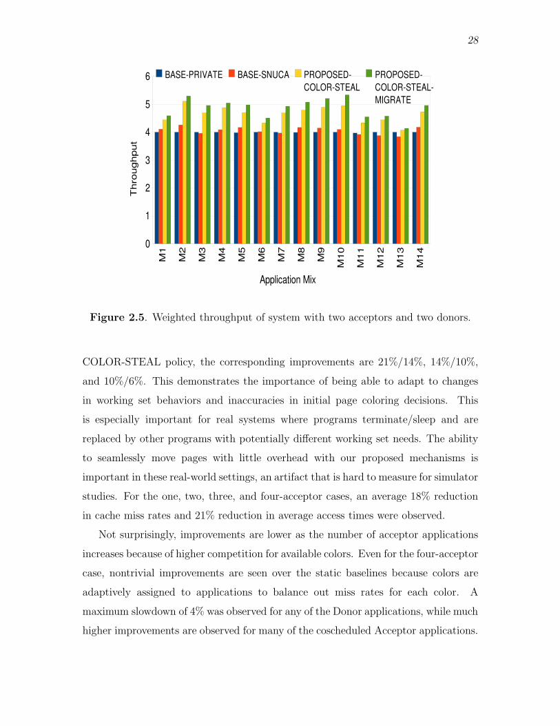
28
Figure 2.5. Weighted throughput of system with two acceptors and two donors.
COLOR-STEAL policy, the corresponding improvements are 21%/14%, 14%/10%,
and 10%/6%. This demonstrates the importance of being able to adapt to changes
in working set behaviors and inaccuracies in initial page coloring decisions. This
is especially important for real systems where programs terminate/sleep and are
replaced by other programs with potentially different working set needs. The ability
to seamlessly move pages with little overhead with our proposed mechanisms is
important in these real-world settings, an artifact that is hard to measure for simulator
studies. For the one, two, three, and four-acceptor cases, an average 18% reduction
in cache miss rates and 21% reduction in average access times were observed.
Not surprisingly, improvements are lower as the number of acceptor applications
increases because of higher competition for available colors. Even for the four-acceptor
case, nontrivial improvements are seen over the static baselines because colors are
adaptively assigned to applications to balance out miss rates for each color. A
maximum slowdown of 4% was observed for any of the Donor applications, while much
higher improvements are observed for many of the coscheduled Acceptor applications.

29
Figure 2.6. Weighted throughput of system with three acceptors and one donor.
As a sensitivity analysis, we show a limited set of experiments for the eight
core system. Figure 2.8 shows the behavior of the two baselines and the two pro-
posed mechanisms for a few four-acceptor, six-acceptor, and eight-acceptor workloads.
The average improvements with PROPOSED-COLOR-STEAL and PROPOSED-
COLOR-STEAL-MIGRATE are 8.8% and 12%, respectively.
2.3.4 Results for Multithreaded Workloads
In this section, we evaluate the page migration policies described in Section 2.2.2.2.
We implement a MESI directory-based coherence protocol at the L1-L2 boundary
with a writeback L2. The benchmarks and their properties are summarized in
Table 2.5. We restrict most of our analysis to the 4 SPLASH-2 and 2 PARSEC
programs in Table 2.5 that have a large percentage of pages that are frequently
accessed by multiple cores. Not surprisingly, the other applications do not benefit
much from intelligent migration of shared pages and are not discussed in the rest of
the paper.
Since all these benchmarks must be executed with smaller working sets to allow for
acceptable simulation times (for example, PARSEC programs can only be simulated
with large input sets, not the native input sets), we must correspondingly also model

30
Figure 2.7. Normalized system throughput as compared to BASE-PRIVATE —Weighted throughput of system with four cores and four acceptors.
a smaller cache size [51]. If this is not done, there is almost no cache capacity pressure
and it is difficult to test if page migration is not negatively impacting pressure in some
cache banks. Preserving the NUCA access times in Table 2.1, we shrink the total L2
cache size to 64 KB. Correspondingly, we use a scaled down page size of 512B. The
L1 caches are 2-way 4KB.
We present results following, first for a four-core CMP, and finally for an eight-core
CMP as a sensitivity analysis. We experimented with two schemes for migrating
shared pages. Proposed-CoG migrates pages to their CoG, without regard for the
destination bank pressure. Proposed-CoG-Pressure, on the other hand, also incorpo-
rates bank pressure into the cost metric while deciding the destination bank. We also
evaluate two other schemes to compare our results. First, we implemented an oracle
placement scheme which directly places the pages at their CoG (with and without
consideration for bank pressure — called Oracle-CoG and Oracle-CoG-Pressure, re-
spectively). These optimal locations are determined based on a previous identical
simulation of the baseline case. Second, we shrink the page size to merely 64 bytes.
Such a migration policy attempts to mimic the state-of-the-art in D-NUCA fine-grain
migration policies that move a single block at a time to its CoG. Comparison against

31
Figure 2.8. Normalized system throughput as compared to BASE-PRIVATE —Weighted throughput for eight core workloads.
Table 2.5. SPLASH-2 and PARSEC programs with their inputs and percentage ofRW-shared pages.
Application Percentage of Application Percentage ofRW-shared pages RW-shared pages
fft(ref) 62.4% water-nsq(ref) 22%cholesky(ref) 30.6% water-spa(ref) 22.2%fmm(ref) 31% blackscholes(simlarge) 24.5%barnes(ref) 67.7% freqmine(simlarge) 16%lu-nonc(ref) 61% bodytrack(simlarge) 19.7%lu-cont(ref) 62% swaptions(simlarge) 20%
ocean-cont(ref) 50.3% streamcluster(simlarge) 10.5%ocean-nonc(ref) 67.2% x264(simlarge) 30%
radix(ref) 40.5%
this baseline gives us confidence that we are not severely degrading performance by
performing migrations at the coarse granularity of a page. The baseline in all these
experiments is BASE-SNUCA.
Figure 2.9 presents the percentage improvement in throughput for the six mod-
els, relative to the baseline. The Proposed-CoG-Pressure model outperforms the
Proposed-CoG model by 3.1% on average and demonstrates the importance of taking
bank pressure into account during migration. This feature was notably absent from

32
Migrating 64B Blocks−CoGProposed−CoGOracle−CoGMigrating 64B Blocks−CoG−PressureProposedCoG−PressureOracle−CoG−Pressure
0%
5%
10%
15%
20%
ocean−nonclu−contfftbarnesblackscholesswaptions
Perc
enta
ge I
mpro
vem
ent
in T
hro
ughput
Figure 2.9. Percentage improvement in throughput.
prior D-NUCA policies (and is admittedly less important if capacity pressures are
nonexistent). By taking bank pressure into account, the number of L2 misses is
reduced by 5.31% on average, relative to Proposed-CoG. The proposed models also
perform within 2.5% and 5.2%, on average, of the corresponding oracle scheme. It
is difficult to bridge this gap because the simulations take fairly long to determine
the optimal location and react. This gap will naturally shrink if the simulations are
allowed to execute much longer and amortize the initial inefficiencies. Our policies are
within 1% on average to the model that migrates 64B pages. While a larger page size
may make suboptimal CoG decisions for each block, it does help prefetch a number
of data blocks into a close-to-optimal location.
To interpret the performance improvements, we plot the percentage of requests
arriving at L2 for data in migrated pages. Figure 2.10 overlays this percentage
with percentage improvement in throughput. The Y-axis represents percentage im-
provement in throughput and percentage of accesses to moved pages. The curves

33
Figure 2.10. Improvement in throughput overlaid with percentage accesses to movedpages.
plot accesses to moved pages and the bars show improvement in throughput. As
can be seen, the curves closely track the improvements as expected, except for
barnes. This is clarified by Figure 2.11 which shows that moving pages towards
central banks can lead to higher network contention in some cases (barnes), and
slightly negate the performance improvements. By reducing capacity pressures on
a bank, the Proposed-CoG-Pressure also has the side effect of lowering network
contention. At the outset, it might appear that migrating pages to central locations
may increase network contention. In most cases, however, network contention is
lowered as network messages have to travel shorter distances on average, thus reducing
network utilization.
Figure 2.12 plots the number of lines flushed due to migration decisions.The
amount of data flushed is relatively small for nearly 1 billion or longer instruction
executions. barnes again is an outlier with the highest amount of data flushed. This
also contributes to its lower performance improvement. The reason for this high
34
Proposed−CoGProposed−CoG−Pressure
−2%
−1%
0%
1%
2%
3%
4%
ocean−nonclu−contfftbarnesblackscholesswaptions
Per
cen
t C
han
ge
in N
etw
ork
Co
nte
nti
on
Ov
er B
asel
ine
Figure 2.11. Percentage change in network contention due to proposed schemes.
amount of data flush is that the sharing pattern exhibited by barnes is not uniform.
The accesses by cores to RW-shared data keeps varying (due to possibly variable
producer-consumer relationship) among executing threads. This leads to continuous
corrections in CoG which further leads to large amount of data flushes.
As a sensitivity analysis of our scheme, for an eight-core CMP we only present
percentage improvement in throughput in Figure 2.13. The proposed policies show
an average improvement of 6.4%.
2.4 Summary and Discussion
In this chapter, we attempted to combine the desirable features of a number of
state-of-the-art proposals in a large cache design. We show that hardware mechanisms
based on shadow address bits are effective in migrating pages within the processor at
low cost. This allows us to design policies to allocate LLC space among competing
threads and migrate shared pages to optimal locations. The resulting architecture
allows for high cache hit rates, low cache access latencies on average, and yields

35
From L2−$(Proposed−CoG)From L1−$(Proposed−CoG)From L2−$(ProposedCoG−Pressure)From L1−$(ProposedCoG−Pressure)
0
5,000
10,000
15,000
20,000
25,000
ocean−nonclu−contfftbarnesblackscholesswaptions
Nu
mb
er o
f D
ata
Lin
es F
lush
ed D
ue
to P
age
Mig
rati
on
Figure 2.12. Number of cache lines flushed due to migration of RW-shared pages.
overall improvements of 10-20% with capacity allocation, and 8% with shared page
migration. The design also entails low complexity for the most part, for example, by
eliminating complex search mechanisms that are commonly seen in way-partitioned
NUCA designs.
As discussed previously, the primary complexity introduced by the proposed scheme
is the translation table (TT) and its management. Addressing this problem is im-
portant future work. One of the ways this problem can be potentially handled is by
allowing the software component of the proposed schemes do a little more work than
just choosing the colors that minimize the cost functions. We also plan to leverage
the page coloring techniques proposed here to design mechanisms for page replication
while being cognizant of bank pressures.

36
Proposed−CoGProposedCoG−Pressure
0%
2%
4%
6%
8%
10%
ocean−nonclu−contfftbarnesblackscholesswaptions
Per
cent
age
Impr
ovem
ent
in T
hrou
ghpu
t fo
r 8−
core
CM
P
Figure 2.13. Throughput improvement for eight-core CMP.

CHAPTER 3
HANDLING LOCALITY CHALLENGES IN
MAIN MEMORY
In the last chapter we explored mechanisms to manage a number of issues in
shared, last-level caches using a hardware-software codesign approach. As a natural
extension, the next level in the memory hierarchy is the main memory, usually DRAM.
In previous years, explicitly managing data locality in DRAM was not much of a
concern because of a number of factors. Firstly, in the uniprocessor era, there were
just a small number of applications running in a context switched fashion. This
provided for enough spatiotemporal locality in the memory access stream. DRAM
modules and associated circuitry were optimized to exploit the existing locality, with
row-buffers and row-buffer-aware scheduling. That view is changing today as pages
from multiple applications can interfere and destroy any available locality.
Secondly, the memory controller (MC) was located off-chip on the Northbridge
chipset and was the single point of access to the DRAM modules. With the advent of
the multicore era, and the changing nature of applications, the way we access memory
has changed. Depending on where a page is placed, the access penalty for that page
may be high and the access penalty for other pages may also be impacted.
Today, each processor has a number of cores on chip. Applications are becoming
exceedingly memory intensive, but there has been little increase in the the number
of pins over the years, which translates into a stagnant off-chip bandwidth. To make
maximal use of available bandwidth, the MC is being integrated on-chip, and as
the number of cores per chip increases, the number of on-chip MCs is expected to
grow accordingly. Also, more and more sockets are being integrated on-chip, each of
them being connected by a proprietary interconnect technology. Even with all these
developments, all processors on a board are part of a single, flat, shared address space.
All these developments lead to the creation of a nonuniform memory access (NUMA)

38
hierarchy, first on a single chip among the various on-chip MCs and associated memory
banks, and then across various sockets on a board.
System software has not kept pace with the vast changes in underlying memory
architectures. Very little has been done to intelligently manage data to decrease
the overall DRAM access latencies, either in software or hardware. In this chapter,
we will explore some mechanisms to manage data in single-chip and single-board
NUMA systems. These include heuristic based page placement and migration mech-
anisms which account for system overheads that minimize DRAM access latencies
in hierarchies with multiple on-chip MCs. In later sections we will also optimize
the proposed mechanisms for main memory architectures comprising heterogeneous
memory technologies and multisocket, single-board NUMA hierarchies.
3.1 Introduction
Modern microprocessors increasingly integrate the memory controller on-chip in
order to reduce main memory access latency. Memory pressure will increase as core-
counts per socket rise resulting in a single MC becoming a bottleneck. In order
to avoid this problem, modern multicore processors (chip multiprocessors, CMPs)
have begun to integrate multiple MCs per socket [24–26]. Similarly, multisocket
motherboards provide connections to multiple MCs via off-chip interconnects such
as AMD’s HyperTransportTM(HT) and Intel’s Quick Path InterconnectTM(QPI). In
both architectures, a core may access any DRAM location by routing its request to
the appropriate MC. Multicore access to a large physical memory space partitioned
over multiple MCs is likely to continue and exploiting MC locality will be critical to
overall system throughput.
Recent efforts [26, 28–30] have incorporated multiple MCs in their designs, but
there is little analysis on how data placement should be managed and how a particular
placement policy will affect main memory access latencies. In addressing this problem,
we show that simply allocating an application’s thread data to the closest MC may
not be optimal since it does not take into account queuing delays, row-buffer conflicts,
and on chip interconnect delays. In particular, we focus on placement strategies which
incorporate: (i) the communication distance and latency between the core and the
MC, (ii) queuing delay at the MC, and (iii) DRAM access latency, which is heavily

39
influenced by row-buffer hit rates. We show that improper management of these
factors can cause a significant degradation in performance.
Further, future memory hierarchies may be heterogeneous. Some DIMMs may be
implemented with PCM devices while others may use DRAM devices. Alternatively,
some DIMMs and channels may be optimized for power efficiency, while others may
be optimized for latency. In such heterogeneous memory systems, we show that
additional constraints must be included in the optimization functions to maximize
performance.
Recently, some attention has been directed towards managing locality in single-
board NUMA systems. Majo et al. [52] propose the NUMA multicore aware schedul-
ing scheme (N-MASS) scheduling algorithm that can be plugged in place of the default
Linux process scheduler. The N-MASS scheduler tries to attach processes to cores in
a NUMA system to decrease (i) the number of nonlocal main memory accesses, and
(ii) contention for shared cache space. Their work, however, is based on sampling
the misses per thousand instruction (MPKI) rates for the associated processes, and
then associating processes to cores to decrease nonlocal DRAM accesses. As an
added optimization, if the combined MPKI of a workload reaches above a certain
threshold (indicating increased cache contention between processes), some processes
are migrated to other cores to minimize the differences between cache pressures.
Their proposal is implemented completely in kernel and does not try to manage data.
Rather, they try to find the best performing process-to-core mapping to address
the problems. A follow-up work by the same authors [53], examines the effects of
bandwidth sharing between remote and locally executing processes at both the on-chip
MC and the interprocessor interconnect in existing Nehalem NUMA organizations.
They conclude that there needs to exist a balance between local and remote main
memory accesses if the overall performance of the system is to be optimized with
maximal utilization of the available off-chip bandwidth. Additionally, they also make
a case for the increasing importance of system overheads like queuing delays at not just
the MC, but also at the interprocessor(socket) interconnect. Pilla et al. [54] propose
a heuristic-based load balancing algorithm that takes into account the underlying
NUMA topology and the characteristics of the underlying application. Since their

40
proposed mechanism relies on collecting nontrivial amount of information about the
application to make a good decision to map threads to cores, they rely heavily on
the CHARM++ runtime system [55]. Additionally, it requires the applications to
use the CHARM++ parallel programming environment, which is not possible to do
for all workloads. More recently, Muralidhara et al. [56] have proposed using an
OS-based approach to increase channel level parallelism between different applica-
tions in a CMP environment. Their approach, however, is an attempt at reducing
interference between memory access of different applications by allocating pages of
different applications across channels so as to reduce interference, without considering
how such decisions might effect data locality.
To our knowledge, this is the first attempt at intelligent data placement in a
multi-MC platform. This work builds upon ideas found in previous efforts to optimize
data placement in last-level shared NUCA caches [4, 12, 20, 21, 46, 57–62]. One key
difference between DRAM and last level cache placement, however, is that caches tend
to be capacity constrained, while DRAM access delays are governed primarily by other
issues such as long queuing delays and row-buffer hit rates. There are only a handful of
papers that explore challenges faced in the context of multiple on-chip MCs. Abts et
al. [30] explore the physical layout of multiple on-chip MCs to reduce contention in the
on-chip interconnect. An optimal layout makes the performance of memory-bound
applications predictable, regardless of which core they are scheduled on. Kim et
al. [63] propose a new scheduling policy in the context of multiple MCs which requires
minimal coordination between MCs. However, neither of these proposals consider
how data should be distributed in a NUMA setting while taking into account the
interaction of row-buffer hit rates, queuing delays, and on-chip network traffic. Our
work takes these DRAM-specific phenomena into account and explores both first-
touch page placement and dynamic page-migration designed to reduce access delays.
We show average performance improvements of 6.5% with an adaptive first-touch
page-coloring policy, and 8.9% with a dynamic page-migration policy. The proposed
policies are notably simple in their design and implementation.
The rest of this chapter is organized as follows: We provide background and
motivational discussion in Section 3.2. Section 3.3 details our proposed adaptive

41
first-touch and dynamic migration policies and Section 3.4 provides quantitative
comparison of the proposed policies. We discuss related work in Section 3.5 and
conclusions in Section 3.6.
3.2 Background and Motivational Results
3.2.1 DRAM Basics
For joint electron device engineering council (JEDEC) based DRAM, each MC
controls one or more dual in-line memory modules (DIMMs) via a bus-based chan-
nel comprising a 64-bit datapath, a 17-bit row/column address path, and an 8-bit
command/control-path [64]. The DIMM consists of eight or nine DRAM chips,
depending on the error correction strategy, and data is typically N -bit interleaved
across these chips; N is typically 1, 4, 8, or 16 indicating the portion of the 64-bit
datapath that will be supplied by each DRAM chip. DRAM chips are logically
organized into banks and DIMMs may support one or more ranks. The bank and
rank organization supports increased access parallelism since DRAM device access
latency is significantly longer than the rate at which DRAM channel commands can
be issued.
Commodity DRAMs are very cost sensitive and have been optimized to minimize
the cost/bit. Therefore, an orthogonal two-part addressing scheme is utilized where
row and column addresses are multiplexed on the 17-bit address channel. The MC
first generates the row address that causes an entire row of the target bank to be read
into a row-buffer. A subsequent column address selects the portion of the row-buffer
to be read or written. Each row-buffer access reads out 4 or 8 kB of data. DRAM
subarray reads are destructive but modern DRAMs restore the subarray contents on
a read by over-driving the sense amps. However, if there is a write to the row-buffer,
then the row-buffer must be written to the subarrays prior to an access to a different
row in the same bank. Most MCs employ some variation of a row-buffer management
policy, with the open-page policy being most favored. An open-page policy maintains
the row-buffer contents until the MC schedules a request for a different row in that
same bank. A request to a different row is called a “row-buffer conflict.” If an
application exhibits locality, subsequent requests will be serviced by a “row-buffer

42
hit” to the currently active row-buffer. Row-buffer hits are much faster to service
than row-buffer conflicts.
In addition to a row-buffer management policy, the MC typically has a queue of
pending requests and must decide how to best schedule requests. Memory controllers
chose the next request to issue by balancing timing constraints, bank constraints,
and priorities. One widely adopted scheduling policy is first ready - first come first
serve (FR-FCFS) [65] that prioritizes requests to open rows and breaks ties based
on age. The requests issued by the memory controller are typically serviced across
a dedicated channel that receives no interference from other memory controllers, nor
having to work with a shared bus. As a result, each memory controller has global
knowledge about what memory access patterns are occurring on their private slice of
physical memory.
3.2.2 Current/Future Trends in MC Design
Several commercial designs have not only moved the MC on chip, but have also
integrated multiple MCs on a single multicore die. Intel’s Nehalem processor [24]
shown in Figure 3.1(a), integrates four cores and one MC with three channels to
double data rate type three synchronous dynamic random access memory (DDR3)
memory. Multiple Nehalem processors in a multisocket machine are connected via a
QPI interconnect fabric. Any core is allowed to access any location of the physical
memory, either via its own local MC or via the QPI to a remote processor’s MC. The
latency for remote memory access, which requires traversal over the QPI interconnect,
is 1.5x the latency for a local memory access (NUMA factor). This change is a
result of on-die MCs: in earlier multisocket machines, memory access was centralized
via off-chip MCs integrated on the north-bridge. This was then connected via a
shared bus to the DIMMs. Similar to Intel’s Nehalem architecture, AMD’s quad-core
Opteron integrates two 72-bit channels to a DDR2 main memory subsystem [25].
The Tile64 processor [26] incorporates four on-chip MCs that are shared among 64
cores/tiles. A specialized on-chip network allows all the tiles to access any of the
MCs, although physical placement details are not publicly available. The Corona
architecture from HP [29] is a futuristic view of a tightly coupled nanophotonic NUMA

43
(A)
(B)
Figure 3.1. Platforms with multiple memory controllers. (A) Logical organizationof a multisocket Nehalem. (B) Assumed sixteen-core four-MC model.
system comprising 64 four-core clusters, where each cluster is associated with a local
MC.
It is evident that as we increase the number of cores on-chip, the number of
MCs on-chip must also be increased to efficiently feed the cores. However, the
international technology roadmap for semiconductors (ITRS) roadmap [66] expects
almost a negligible increase in the number of pins over the next 10 years, while Moore’s

44
law implies at least a 16x increase in the number of cores. Clearly the number of
MCs cannot scale linearly with the number of cores. If it did, the number of pins per
MC would reduce dramatically, causing all transfers to be heavily pipelined leading
to long latencies and heavy contention, which we will show in Section 3.4. The
realistic expectation is that future many-core chips will accommodate a moderate
number of memory controllers, with each MC servicing requests from a subset of
cores. This is reflected in the layout that we assume for the rest of this paper, shown
in Figure 3.1(b). Sixteen cores share four MCs that are uniformly distributed at
the edge of the chip. On-chip wire delays are an important constraint in minimizing
overall memory latency, this simple layout of memory controls helps minimize the
average memory controller to I/O pin and core distance.
While fully buffered DIMM (FB-DIMM) designs [67] are not very popular today,
the FB-DIMM philosophy may eventually cause a moderate increase in the number
of channels and MCs. In order to increase capacity, FB-DIMM replaces a few wide
channels with many skinny channels, where each channel can support multiple daisy-
chained DIMMs. Skinny channels can cause a steep increase in data transfer times
unless they are accompanied by increases in channel frequency. Unfortunately, an
increase in channel frequency can, in turn, cause power budgets to be exceeded.
Hence, such techniques may cause a small increase in the number of channels and
MCs on a single processor to find the appropriate balance between energy efficiency
and parallelism across multiple skinny channels.
Finally, there is a growing sentiment that future memory systems are likely to
be heterogeneous. In order to alleviate the growing concerns over memory energy,
some memory channels and DIMMs may be forced to operate at lower frequencies
and voltages [68, 69]. While FB-DIMM and its variants provide higher capacity,
they cause a steep increase in average latency and power. Therefore, they may be
employed in a limited extent for a few memory channels, yielding heterogeneous
properties for data access per channel. New memory technologies, such as PCM [70],
exhibit great advantages in terms of density, but have poor latency, energy, and
endurance properties. We believe that future memory systems are likely to use a
mix of FB-DIMM, DDRx (x referring to future process generations), and PCM nodes

45
within a single system. We therefore consider heterogeneous properties of DIMMs
as a first class input into the cost functions used to efficiently place memory across
various NUMA nodes.
3.2.3 OS Support for DRAM/NUMA Systems
There has been very little research on the OS perspective of managing the memory
hierarchy in the previously described single -chip and -board NUMA hierarchies. The
most current perspective of NUMA support within the Linux kernel is provided by
Lameter [71]. Lameter’s paper is geared towards symmetric multi-processor (SMP)
systems, where each of the nodes (with multiple processors each) were connected via
a very high latency and bandwidth restricted interconnect. In such an organization,
the kernel would try to allocate memory on the “local” node’s memory, but will
have to resort to allocating memory at “remote” nodes if local memory allocation is
impossible. NUMA support for SMP systems also included mechanisms to reclaim
inactive page belonging to the page or buffer cache. There is also support to migrate
pages if need be via explicit calls to the OS.
There has also been some research in development of a user-level library [72].
Libnuma [72] has been made available for Linux. It allows the user carry out explicit
memory management of the user program by making calls to the OS from within the
program. As an additional support, if the workloads executing on a machine do not
change frequently, system-wide policy assignments can be made to optimize memory
management for the specific class of workloads.
Although there is some existing support from the OS for NUMA memory man-
agement, we feel that for the next-generation, single-board NUMA architectures
described in Section 3.2.2, will require substantial rework of the original implemen-
tations, which were optimized for ccNUMA/SMP architectures. All programmers
cannot be expected to optimize memory management for each and every program,
for (potentially) hundreds of different NUMA hierarchies that will be on the market
sometime soon. Hence, there exists a need to make memory management transparent
to the programmer. In the later sections, we will provide data to motivate the problem
of managing data locality in main memory and design strategies to achieve this goal.

46
3.2.4 Motivational Data
This paper focuses on the problem of efficient data placement at OS page granu-
larity, across multiple physical memory slices. The related problem of data placement
across multiple last-level cache banks has received much attention in recent years, with
approaches such as cooperative caching [57], page spilling [20], and their derivatives
[4, 12, 21, 46, 58–62] being the most well known techniques. There has been little
prior work on OS-based page coloring to place pages in different DIMMs or banks to
promote either DIMM or bank-level parallelism (Zhang et al. [27] propose a hardware
mechanism within the memory controller to promote bank-level parallelism). The
DRAM problem has not received as much attention because there is a common mis-
conception that most design considerations for memory controller policy are dwarfed
by the long latency for DRAM chip access. We argue that as contention at the
memory controller grows, this is no longer the case.
As mentioned in Section 3.2.1, the NUMA factor in modern multisocket systems
can be as high as 1.5 [24]. This is because of the high cost of traversal on the off-chip
QPI/HT network as well as the on-chip network. As core count scales up, wires emerge
as bottlenecks. As complex on-chip routed networks are adopted, one can expect tens
of cycles in delay when sending requests across the length of the chip [26, 73], further
increasing the NUMA disparity.
Pin count restrictions prevent the memory controller count from increasing linearly
with the number of cores, while simultaneously maintaining a constant channel width
per MC. Thus, the number of cores serviced by each MC will continue to rise,
leading to contention and long queuing delays within the memory controller. Recent
studies [74–78] have identified MC queuing delays as a major bottleneck and have
proposed novel mechanisms to improve scheduling policies. To verify these claims,
we evaluated the impact of increasing core counts on queuing delay when requests
are serviced by just a single memory controller. Section 3.4 contains a detailed
description of the experimental parameters. For the results shown in Figure 3.2,
each application was run with a single thread and then again with 16 threads, with
one thread pinned on every core. The average queuing delay within the memory
controller across 16-threads, as compared to just one thread, can be as high as 16x

47
Figure 3.2. Relative queuing delays for 1 and 16 threads, single MC, 16 cores.
(Bodytrack). The average number of cycles spent waiting in the MC request queue
was as high as 280 CPU cycles for the 16-thread case. This constitutes almost half
the time to service an average (495 cycles) memory request, making a strong case
for considering queuing delays for optimized data placement across multiple memory
controllers.
When considering factors for optimizing memory placement, it is important to
maximize row-buffer hit rates. For DDR3-1333, there is a factor of 3 overhead, 25
to 75 DRAM cycles, when servicing row-buffer hits versus conflict misses. Figure 3.3
shows row-buffer hit rates for a variety of applications when running with one, four,
and eight-threads. These measurements were made using hardware performance
counters [79] on a dual-socket, quad-core AMD Opteron 2344HE system with 16
2-GB DIMMs. While there is significant variation in the row-buffer hit rate among
applications, the key observation is that in all cases moving from a single to multiple
threads decreases the average row-buffer hit rate seen at the memory controllers due
to more frequent row-buffer conflicts. This supports our hypothesis that there is con-

48
Figure 3.3. Row-buffer hit rates, dual-socket, quad-core Opteron.
tention within the memory controller that is reducing the effectiveness of open-page
policy and it may be possible to alleviate some of this contention through intelligent
placement of application data across memory controllers.
Three important observations that we make from the above discussion are: (i)
NUMA factor is likely to increase in the future as the relative contribution of wire
delay increases. (ii) Higher core and thread counts per memory controller lead to
high MC contention, raising the importance of actively tracking and managing MC
properties such as queuing delay. (iii) Increased interleaving of memory accesses from
different threads leads to a reduction in row-buffer hit rates. (iv) Intelligent memory
placement policy must balance all three of these first order effects when choosing
where to allocate data to physical memory slice.
3.3 Proposed Mechanisms
We are interested in developing a general approach to minimize memory access
latencies for a system that has many cores, multiple MCs, with varying interconnect
latencies between cores and MCs. For this study, we assume a 16-core processor with
49
four MCs, as shown in Figure 3.1(b) where each MC handles a distinct subset of the
aggregate physical address space and the memory requests (L2 misses) are routed to
the appropriate MC based on the physical memory address. The L2 is shared by all
cores, and physically distributed among the 16 tiles in a tiled S-NUCA layout [4, 5].
Since the assignment of data pages to an MC’s physical memory slice is affected by
the mapping of virtual addresses to physical DRAM frames by the OS, we propose
two different schemes that manage/modify this mapping to be aware of the DIMMs
directly connected to an MC.
When a new virtual OS page is brought into physical memory, it must be assigned
to a DIMM associated with a single MC and a DRAM channel associated with
that MC. Proper assignment of pages attempts to minimize access latency to the
newly assigned page without significantly degrading accesses to other pages assigned
to the same DIMM. Ultimately, DRAM access latency is strongly governed by the
following factors: (i) the distance between the requesting core and the MC, (ii) the
interconnection network load on that path, (iii) the average queuing delay at the
MC, (iv) the amount of bank and rank contention at the targeted DIMM, and (v)
the row-buffer hit rate for the application. To make intelligent decisions based on
these factors, we must be able to both monitor and predict the impact that assigning
or moving a new memory page will have on each of these parameters. Statically
generating profiles offline can help in page assignment, but this is almost never
practical. For this work, we focus on policies that rely on run-time estimation of
application behavior.
To reduce memory access delays we propose: adaptive first-touch placement of
memory pages, and dynamic migration of pages among DIMMs at the OS page
granularity. The first scheme is based on DRAM frame allocation by the OS which
is aware of MC load (queuing delays, row-buffer hit rates and bank contention) and
the on-chip distance between the core the thread is executing on and the MC that
will service requests to this frame. We propose modifications to the OS memory
allocator algorithm so that it is aware of these factors in order to create improved
virtual-to-physical mappings only when natural page-faults occur. The second scheme
aims to dynamically migrate data at run-time to reduce access delays. This migration

50
of pages occurs when there is excess memory bandwidth to support remapping oper-
ations. We also propose mechanisms that allow dynamic migration to occur without
stalling CPUs that are accessing the pages being migrated.
3.3.1 Adaptive First-Touch (AFT) Page Placement Policy
In the common case, threads/tasks1 will be assigned to cores rather arbitrarily
based on program completion times and task queues maintained by the OS for each
core. The OS task scheduling algorithm could be modified to be aware of multiple-
MCs and leverage profile based aggregated MC metrics to intelligently schedule tasks
to cores. Clever task scheduling must rely on precomputed profiles that can be
inaccurate and are closely tied to the behavior of coscheduled applications; this
makes achieving a general purpose approach challenging. Instead, we believe that
intelligently placing data, such that the overall throughput of the system is improved,
is likely to out-perform coarse grained task scheduling optimization because of the
fine granularity at which changes to the memory mappings can be made and updated
at run-time.
In our adaptive first-touch approach for page allocation, when a thread starts
executing on some core, each new page it touches will generate a page fault. At this
time, the virtual page is assigned to a DRAM frame (physical page) such that it is
serviced by an MC that minimizes an objective cost function. The intuition behind
the objective function is that most pages associated with a thread will be mapped
to the nearest MC, with a small number of pages being spilled to other nearby MCs,
only when beneficial to overall performance. The following cost function is computed
for each new page and for each MC j:
costj = α× loadj + β × rowhitsj + λ× distancej
where loadj is the average queuing delay at MC j, rowhitsj is the average row-buffer
hit rate seen by MC j, and distancej is the distance between the core requesting the
memory page and the MC, in terms of number of interconnect hops that need to be
traversed. The role of load and distance is straightforward; the row-buffer hit rate
1We use threads and tasks interchangeably in the following discussion, unless otherwise specified.

51
is considered based on the assumption that the new page will be less disruptive to
other accesses if it resides in a DIMM with an already low row-buffer hit rate. The
relative importance of each factor is determined by the weights α, β, and λ. After
estimating the cost function for each MC, the new page is assigned to the MC that
minimizes the cost function. In essence, this is done by mapping the virtual page to
a physical page in the slice of memory address space being controlled by the chosen
MC j. Since allocation of new DRAM frames on a page-fault is on the critical path,
we maintain a small history of the past few (5) runs of this cost function for each
thread. If two consecutive page faults for a thread happen within 5000 CPU cycles of
each other, the maximally recurring MC from the history is automatically chosen for
the new page as well. Once the appropriate MC is selected, a DRAM frame managed
by this MC is allocated by the OS to service the page-fault.
3.3.2 Dynamic Page Migration Policy
While adaptive first-touch can allocate new pages efficiently, for long-running
programs that are not actively allocating new pages, we need a facility to react to
changing program phases or changes in the environment. We propose a dynamic
data migration scheme that tries to adapt to this scenario. Our dynamic migration
policy starts out with the AFT policy described above. Then during the course of
the program execution, if an imbalance is detected in DRAM access latency between
memory controllers, we choose to migrate N pages from the highest loaded MC to
another one. Decisions are made every epoch, where an epoch is a fixed time interval.
The above problem comprises of two parts :- (i) finding which MC is loaded and
needs to shed load (the donor MC), and (ii) deciding the MC that will receive the
pages shed by the donor (recipient MC). For our experiments, we assume if an MC
experiences a drop of 10% or more in row-buffer hit rates from the last epoch, it is
categorized as a donor MC2. When finding a recipient MC, care has to be taken that
the incoming pages do not disrupt the locality being experienced at the recipient. As
a first approximation, we choose the MC which (i) is physically proximal to the donor
2This value can be made programmable to suit a particular workload’s needs. After extensiveexploration, we found that 10% works well across all workloads that we considered.
52
MC, and (ii) has the lowest number of row-buffer hits in the last epoch. Hence for
each MC k in the recipient pool, we calculate
costk = Λ× distancek + Γ× row hitsk
The MC with least value for the above cost is selected as the recipient MC. Once
this is done, N least recently used pages at the donor MC are selected for migration.
It is possible to be more selective regarding the choice of pages and the choice of
new MC, but we resort to this simple policy because it is effective and requires very
few resources to implement. We note that even when the dynamic migration policy is
in use, freshly allocated pages are steered towards the appropriate MCs based on the
AFT cost function. Pages that have been migrated are not considered for remigration
for the next two epochs to prevent thrashing of memory across memory controllers.
When migrating pages, the virtual address of the page does not change, but the
physical location does. Thus, to maintain correctness two steps need to be taken for
pages that are undergoing migration:
1. Cache Invalidate: The cache lines belonging to the migrated pages have to be
invalidated across all cores. With our S-NUCA cache, only one location must
be looked up for each cache line. When invalidating the lines, copies in L1 must
also be invalidated through the directory tracking these entries forcing any dirty
data to be written back to memory prior to migration occurring.
2. TLB Update: TLBs in all cores have to be informed of the change in the
page’s physical address. Therefore any core with an active TLB mapping must
be updated after the page is physically migrated.
Both of these steps are costly in terms of both power and performance. Thus,
premature page migration is likely to result in decreased system performance. Instead,
migration should only occur when the anticipated benefit outweighs the overhead of
page migration.
To avoid forcing an immediate write back of dirty data when migrating pages, we
propose a mechanism that delays the write-back and forwards any dirty data that are
flushed to the new physical page rather than the old. To do this, we defer invalidating
the TLB entry until an entire page has been copied to its new physical location. Any
incoming read requests for the page can still be serviced from the old physical location.
53
Writebacks to the old page are deferred (queued up in the memory controller’s write
buffer). Only after the page has been copied is the TLB shootdown triggered, forcing
a cache write back. The memory controller servicing requests from the old page is
notified that is should redirect writes intended for the old physical location N to the
new physical location M on an alternate memory controller. With this redirection
in place, a TLB shootdown is issued triggering the write back if there are dirty data,
and finally the old physical page can be deallocated and returned to the free page
list. Only then can the memory controller be instructed to stop forwarding requests
to the alternate location, and normal execution resumes. This method of delaying
TLB shootdowns is referred to as lazy-copying in later sections.
3.3.3 Heterogeneous Memory Hierarchy
Previously in Sections 3.3.1 and 3.3.2, we assumed a homogeneous memory system
with DRAM DIMMs attached to all the MCs. However, future memory systems will
likely be comprised of different memory technologies. These memory technologies
will differ in a number of facets, with access latencies and bit-density being the two
important factors considered in this work. There may also be different channel and
wire protocols for accessing a particular memory type, but for this study we assume
a unified standard which allows us to focus on the memory controller issues, not
memory technology properties.
We assume a scenario where memory controllers in the system can only access
one of two possible types of technologies in the system. For example, in the 4-MC
model, one MC controls a gang of DDR3 DIMMs, while the rest control FB-DIMMs.
Alternatively, the NUMA architecture might comprise two MCs controlling DDR3
DRAM while the other two MCs are controlling PCM based devices. For heteroge-
neous memory hierarchies, there is an inherent difference between the capacity and
latency of different devices (listed in Table 3.1). As a result, a uniform cost function
for device access across the entire memory space cannot be assumed; care has to be
taken to assign/move heavily used pages to faster memory (e.g., DRAM), while pages
that are infrequently used can be moved to slower, but denser regions of memory (e.g.,
PCM). To account for the heterogeneity in such systems, we modify the cost function
for the adaptive first-touch policy as follows. On each new page allocation, for each

54
Table 3.1. DRAM timing parameters [1, 2].
Parameter DRAM DRAM PCM Description
(DDR3) (Fast)tRCD 12.5ns 9ns 55ns interval between row
access command and dataready at the sense amps
tCAS 12.5ns 12.5ns 12.5ns interval between columnaccess command and thestart of data burst
tRP 12.5ns 12.5ns 12.5ns time to precharge a rowtWR 12.5ns 9ns 125ns time between the end of
a write data burstand a subsequent prechargecommand to the same bank
tRAS 45ns 45ns 45ns minimum interval betweenrow access andprecharge to same bank
tRRD 7.5ns 7.5ns 7.5ns minimum gap betweenrow access commandsto the same device
tRTRS 2 Bus 2 Bus 2 Bus rank-to-rank switching delayCycles Cycles Cycles
tFAW 45 ns 45 ns 45 ns rolling time windowwithin which maximumof four bank activationscan be made to a device
tWTR 7.5ns 7.5ns 7.5ns delay between a writedata burst anda column read commandto the same rank
tCWD 6.5ns 6.5ns 6.5ns minimum delay betweena column access commandand the write data burst
MCj , we evaluate the following cost function:
costj = α×loadj+β×rowhitsj+λ×distancej+τ×LatencyDimmClusterj+µ×Usagej
(3.1)
The new term in the cost function, LatencyDimmClusterj , is indicative of the
latency of a particular memory technology. This term can be made programmable
(with the average or worst case access latency), or can be based on runtime in-
formation collected by the OS daemon. Usagej represents the percentage of DIMM
capacity that is currently allocated; it is intended to account for the fact that different
memory technologies have different densities and pages must be allocated to DIMMs

55
in approximately that proportion. As before, the MC with the least value of the cost
function is assigned the new incoming page.
Long running applications tend to touch a large number of pages, with some of
them becoming dormant after a period of initial use as the application moves through
distinct phases of execution. To optimize our memory system for these pages we
propose a variation of our initial dynamic page migration policy. In this variation
we target two objectives: (i) for pages that are currently dormant or sparingly used
in the faster memory nodes, these pages can be migrated onto a slower memory
node, further reducing the pressure on faster node. (ii) Place infrequently used pages
in higher density memory (PCM) allowing more space for frequently used pages in
the faster and lower capacity memory (DRAM). A dynamic migration policy for
heterogeneous memory can be of two distinct flavors: (i) pages from any MC can
be migrated to any other MC without considering the memory technology attached
to it. (ii) The policy is cognizant of the memory technology. When the memory
technologies considered are extremely different in terms of latency and density, only
policy (ii) is considered. In the former case, the pool of recipient MCs is all MCs
except the donor. In the latter, the pool is restricted to MCs with only slower devices
attached to them. The recipient cost function remains the same in both cases.
3.3.4 Overheads of Estimation and Migration
Employing any of the proposed policies incurs some system-level (hardware and
OS) overheads. The hardware (MC) needs to maintain counters to keep track of
per-workload delay and access counts, which most of the modern processors already
implement for measuring memory system events (Row-Hits/Misses/Conflicts) [79].
In order to calculate the value of the cost function, a periodic system-level daemon
has to read the values from these hardware counters. Currently, the only parameter
that cannot be directly measured is load or queuing delay. However, performance
monitoring tools can measure average memory latency easily. The difference between
the measured total memory latency and the time spent accessing devices (which is
known by the memory controller when negotiating channel setup) can provide an
accurate estimate of load. We expect that future systems will include hardware
counters to directly measure load.

56
Migrating pages across memory nodes requires trapping into the OS to update
page-table entries. Because we only perform dynamic migration when there is excess
available memory bandwidth, none of these operations are typically on the appli-
cation’s critical path. However, invalidating the TLB on page migration results
in a requisite miss and ensuing page-table walk. We include the cost of this TLB
shootdown and page table walk in all experiments in this study. We also model the
additional load of copying memory between memory controllers via the on-chip net-
work. We chose not to model data transfers via DMA because of the synchronization
complexity it would introduce into our relatively simple migration mechanism. Also,
our simulation framework does not let us quantify the associated costs of DMA, only
page migrations.
3.4 Results
The full system simulations are built upon the Simics [49] platform. Out-of-order
and cache timings are simulated using Simics’ ooo-micro-arch and g-cache modules,
respectively. The DRAM memory subsystem is modeled in detail using a modified
version of Simics’ trans-staller module. It closely follows the model described by Gries
in [1]. The memory controller (modeled in trans-staller) keeps track of each DIMM
and open rows in each bank. It schedules the requests based on open-page and closed-
page policies. The details pertaining to the simulated system are shown in Table 3.2.
Other major components of Gries’ model that we adopted for our platform are: the
bus model, DIMM and device models, and overlapped processing of commands by the
memory controller. Overlapped processing allows simultaneous processing of access
requests on the memory bus, while receiving further requests from the CPU. This
allows hiding activation and precharge latency using the pipelined interface of DRAM
devices. We model the CPU to allow nonblocking load/store execution to support
overlapped processing. Our MC scheduler implements an FR-FCFS scheduling policy
and an open-page row-buffer management policy. PCM devices are assumed to be
built along the same lines as DRAM. We adopted the PCM architecture and timing
parameters from [2]. Details of DRAM and PCM timing parameters are listed in
Table 3.1.

57
Table 3.2. Simulator parameters.
ISA UltraSPARC III ISAL1 I-cache 32KB/2-way, 1-cycle
L2 Cache (shared) 2 MB/8-way, 3-cycle/bank accessHop Access time 2 cycles
(Vertical and Horizontal)Processor frequency 3 GHz
On-chip network width 64 bitsCMP size and Core Freq. 16-core, 3 GHz
L1 D-cache 32KB/2-way, 1-cycleL1/L2 Cache line size 64 BytesRouter Overhead 3 cycles
Page Size 4 KBOn-Chip Network frequency 3 GHz
Coherence Protocol MESIDRAM Parameters
DRAM Device Parameters Micron MT41J256M8 DDR3-800Timing parameters [80],2 ranks, 8 banks/device,32768 rows/bank, x8 part
DIMM Configuration 8 Non-ECC un-buffered DIMMs,64 bit channel, 8 devices/DIMM
DIMM-level Row-Buffer Size 8KB/DIMMActive row-buffers per DIMM 8 (each bank in a device
maintains a row-buffer)Total DRAM Capacity 4 GBDRAM Bus Frequency 1600MHz
Values of Cost Function Constantsα, β, λ,Λ,Γ, τ, µ 10, 20, 100, 200, 100, 20, 500
DRAM address mapping parameters for our platform were adopted from the
DRAMSim framework [81], and were assumed to be the same for PCM devices. We
implemented basic SDRAM mapping, as found in user-upgradeable memory systems,
(similar to Intel 845G chipsets’ DDR SDRAM mapping [82]). Some platform specific
implementation suggestions were taken from the Vasa framework [83]. Our DRAM
energy consumption model is built as a set of counters that keep track of each of
the commands issued to the DRAM. Each precharge, activation, CAS, write-back
to DRAM cells etc. is recorded and total energy consumed reported using energy
parameters derived from a modified version of CACTI [8]. Since pin-bandwidth is

58
limited (and will be in the future), we assume a constant bandwidth from the chip
to the DRAM subsystem. In case of multiple MCs, bandwidth is equally divided
among all controllers by reducing the burst-size. We study a diverse set of workloads
including PARSEC [50] (with sim-large working set), SPECjbb2005 (with number
of warehouses equal to number of cores) and Stream benchmark (number of threads
equal to number of cores).
For all experiments involving dynamic page migration with homogeneous memory
subsystem, we migrate 10 pages (N = 10, section 3.3) from each MC 3, per epoch.
An Epoch is 5 million cycles long. For the heterogeneous memory subsystem, all
pages that have not been accessed in the last two consecutive epochs are migrated to
appropriate PCM MCs.
We (pessimistically) assume the cost of each TLB entry invalidation to be 5000
cycles. We warm-up caches for 25 million instructions and then collect statistics for
the next 500 million instructions. The weights of the cost function were determined
after an extensive design space exploration.4 The L2 cache size was scaled down to
resemble an MPKI (misses per thousand instructions) of 10.6, which was measured
on the real system described in Section 3.2 for PARSEC and commercial workloads.
3.4.1 Metrics for Comparison
For comparing the effectiveness of the proposed schemes, we use the total system
throughput defined as∑
i (IPC ishared/IPC i
alone) where IPC ishared is the IPC of pro-
gram i in a multicore setting with one or more shared MCs. IPC ialone is the IPC of
program i on a stand-alone single-core system with one memory controller.
We also report queuing delays which refer to the time spent by a memory request
at the memory controller waiting to get scheduled plus the cycles spent waiting to get
control of DRAM channel(s). This metric also includes additional stall cycles accrued
traversing the on-chip network.
3Empirical evidence suggested that moving more than 10 pages at a time significantly increasedthe associated overheads, hence decreasing the effectiveness of page migrations.
4We report results for the best performing case.

59
3.4.2 Multiple Memory Controllers — Homogeneous
DRAM Hierarchy
First we study the effect of multiple MCs on the overall system performance for
the homogeneous DRAM hierarchy (Figures 3.4 and 3.5). We divide the total physical
address space equally among all MCs, with each MC servicing an equal slice of the
total memory address space. All MCs for these experiments are assumed to be located
along chip periphery (Figure 3.1(b)). The baseline is assumed to be the case where
OS page allocation routine tries to allocate the new page at the nearest (physically
proximal) MC. If no free pages are available at that MC, the next nearest one is
chosen.
For a fixed number of cores, additional memory controllers improve performance
up to a given point (4 controllers for 16 cores), after which the law of diminishing
returns starts to kick in. On an average across all workloads, as compared to a single
MC, four MCs help reduce the overall queuing delay by 47% and improve row-buffer
hits by 28%, resulting in an overall throughput gain of 15%. Adding more than four
MCs to the system still helps overall system throughput for most workloads, but
Figure 3.4. Impact of multiple memory controllers, homogeneous hierarchy— number of controllers versus throughput.

60
Figure 3.5. Impact of multiple memory controllers, homogeneous hierarchy— number of controllers versus average queuing delays.
for others, the benefits are minimal because (i) naive assignment of threads to MCs
increases interference and conflicts, and (ii) more MCs lead to decreased memory
channel widths per MC, increasing the time taken to transfer data per request and
adding to overall queuing delay. Combined, both these factors eventually end up
hurting performance. For example, for an eight MC configuration, as compared to a
four MC case, ferret experiences increased conflicts at MC numbers 3, 5 and 7, with
the row-buffer hit rates going down by 13%, increasing the average queuing delay by
24%. As a result, the overall throughput for this workload (ferret) goes down by 4%.
This further strengthens our initial assumption that naively adding more MCs does
not solve the problem and makes a strong case for intelligently managing data across
a small number of MCs. Hence, for all the experiments in the following sections, we
use a four MC configuration.
61
3.4.2.1 Adaptive First-Touch and Dynamic Migration
Policies — Homogeneous Hierarchy
Figures 3.6 and 3.7 compare the change in row-buffer hit rates and average
throughput improvement of adaptive first-touch and dynamic migration policies for
the homogeneous DRAM hierarchy over the baseline. On an average, over all the
workloads, adaptive first-touch and dynamic page-migration perform 6.5% and 8.9%
better than the baseline, respectively. Part of this improvement comes from the
intelligent mapping of pages to improve row-buffer hit rates, which are improved by
15.1% and 18.2%, respectively, for first-touch and dynamic migration policies. The
last cluster in Figure 3.6 (STDDEV) shows the standard deviation of individual MC
row-buffer hits for the three policies. In essence, a higher value of this statistic implies
that one (or more) MC(s) in the system is (are) experiencing more conflicts than
others, hence providing a measure of load across MCs. As compared to the baseline,
adaptive first-touch and dynamic migration schemes reduce the standard deviation
by 8.3% and 21.6%, respectively, hence fairly distributing the system DRAM access
load across MCs. Increase in row-buffer hit rates has a direct impact on queuing
delays, since a row-buffer hit costs less than a row-buffer miss or conflict, allowing
the memory system to be freed sooner to service other pending requests.
For the homogeneous memory hierarchy, Figure 3.8 shows the breakdown of total
memory latency as a combination of four factors: (i) queuing delay (ii) network delay
— the extra delay incurred for traveling to a “remote” MC, (iii) device access time,
which includes the latency reading(writing) data from(to) the DRAM devices and (iv)
data transfer delay. For the baseline, a majority of the total DRAM access stall time
(54.2%) is spent waiting in the queue and accessing DRAM devices (25.7%). Since
the baseline configuration tries to map a group of physically proximal cores onto an
MC, the network delay contribution to the total DRAM access time is comparatively
smaller (13.4%). The adaptive policies change the dynamics of this distribution. Since
some pages are now mapped to “remote” MCs, the total network delay contribution
to the average memory latency goes up (to 18% and 28% for adaptive first-touch
and dynamic page migration schemes, respectively). Because of increased row-buffer
hit rates, the device access time contribution to the overall access latency goes down

62
Figure 3.6. Row-buffer hit rate comparison for adaptive first-touch and dynamicmigration policies versus baseline for homogeneous hierarchy.
for the proposed policies, (down by 1.5% and 11.1% for adaptive first-touch and
dynamic migration, respectively), as compared to baseline. As a result, the overall
average latency for a DRAM access goes down from 495 cycles to 385 and 342 CPU
cycles for adaptive first-touch and dynamic migration policies, respectively.
Table 3.3 presents the overheads associated with the dynamic migration policy.
Applications which experience a higher percentage of shared-page migration (flu-
idanimate, streamcluster and ferret) tend to have higher overheads. Compared to
baseline, the three aforementioned applications see an average of 13.5% increase in
network traffic as compared to an average 4.2% increase between the rest. Because of
higher costs of shared-page migration, these applications also have a higher number
of cacheline invalidations and writebacks.
Figure 3.9 compares the effects of proposed policies for a different physical layout
of MCs for the homogeneous DRAM hierarchy. As opposed to earlier, these configu-
rations assume MCs are located at the center of the chip rather than the periphery
(similar to layouts assumed in [30]). We compare the baseline, adaptive first-touch
(AFT) and dynamic migration (DM) policies for both the layouts: periphery and
center. For almost all workloads, we find that baseline and AFT policies are largely

63
Figure 3.7. Relative throughput performance for adaptive first-touch and dynamicmigration policies versus baseline in homogeneous hierarchy.
agnostic to choice of MC layout. Being a data-centric scheme, dynamic migration
benefits a little from the new layout. Although, due to the reduction in the number
of hops, DM-center performs marginally better than DM-periphery.
3.4.2.2 Effects of TLB Shootdowns
To study the performance impact of TLB shootdowns in the dynamic migration
scheme, we increased the cost of each TLB shootdown from 5000 cycles (as assumed
previously) to 7500, 10,000 and 20,000 cycles. Since shootdowns are fairly uncommon,
and happen only at epoch boundaries, the average degradation in performance in
going from 5000 to 20,000 cycles across all applications is 5.8%. For the three
applications that have significant sharing among threads (ferret, streamcluster, flu-
idanimate), the average performance degradation for the same jump is a little higher,
at 6.8%.
3.4.3 Sensitivity Analysis
3.4.3.1 Results for Multisocket Configurations
To test the efficacy of our proposals in the context of multisocket configurations, we
carried out experiments with a configuration similar to one assumed in Figure 3.1(a).

64
Figure 3.8. DRAM access latency breakdown (CPU cycles) for homogeneoushierarchy.
In these experiments, we assume a four-socket system; each socket housing a quad-core
chip, with similar configuration as assumed in Table 3.2. Each quad-core incorporates
one on-chip MC which is responsible for a quarter of the total physical address space.
Each quad-core has similar L1s as listed in Table 3.2, but the 2 MB L2 is equally
divided among all sockets, with each quad-core receiving 512 KB L2. The intersocket
latencies are based on the observations in [84] (48 ns). The baseline, as before, is
assumed to be where the OS is responsible for making page placement decisions. The
weights of the cost function are also adjusted to place more weight to distancej , when
picking donor MCs.
We find that adaptive first-touch is not as effective as the earlier single socket op-
timization, with performance benefits of 1% over baseline. For the dynamic migration
policy, to reduce the overheads of data copying over higher latency intersocket links,
we chose to migrate five pages at a time. Even with these optimizations, the overall
improvement in system throughput was 1.3%. We attribute this to the increased
latency of cacheline invalidations and copying data over intersocket links.

65
Table 3.3. Dynamic page migration overhead characteristics.
Benchmark Total number of Total Cacheline Page copyingPages copied Invalidations + Overhead (Percent increase
(Shared/Un-Shared) Writebacks in network traffic)Blackscholes 210 (53/157) 134 5.8%Bodytrack 489 (108/381) 365 3.2%Facesim 310 (89/221) 211 4.1%
Fluidanimate 912 (601/311) 2687 12.6%Freqmine 589 (100/489) 856 5.2%Swaptions 726 (58/668) 118 2.4%
Vips 998 (127/871) 232 5.6%X264 1007 (112/895) 298 8.1%
Canneal 223 (28/195) 89 2.1%Streamcluster 1284 (967/317) 3018 18.4%
Ferret 1688 (1098/590) 3453 15.9%SPECjbb2005 1028 (104/924) 499 4.1%
Stream 833 (102/731) 311 3.5%
3.4.3.2 Effects of Individual Terms in Cost Functions
In this section we will try to quantitatively justify the choice of the terms in the
cost function. To this end, we try to assess if the quality of decisions being made
changes with the terms in the cost function, and if it does, by how much.
In this analysis, we try and study the effects of how individual terms in the cost
function effect the proposed policies. To this end, we designed two sets of experiments.
In the first set, we take one of the terms out of the cost function and make our
decisions based on the remaining terms. In the second set of experiments, we remove
all but one of the factors and make the decisions based on the remaining terms.
Figure 3.10 provides the results of the former set of experiments for the adaptive
first-touch policy. We find that just considering one term of the cost function leads
to a significant performance drop as compared to all three being considered. Also, we
find that considering just row-buffer hits or queuing delay leads to better decisions
than just considering physical proximity, or distance as the decision metric. This is
evident from the fact that the worst data placement decisions are made based on
just the distance factor, leading to an average performance degradation of 37% as
compared to AFT.

66
Figure 3.9. Throughput sensitivity to physical placement of MCs, dynamic pagemigration policy for homogeneous hierarchy.
In the second set of experiments, we remove just one term from the original
cost function. This gives rise to three different cost functions with two terms each.
Figure 3.11 provides the results of these experiments. We notice that a combination
of two functions makes for better decision making in page placement decisions and
is able to place data in a better fashion. As compared to AFT, the combination
of queuing delays and row-buffer hits as the cost function makes the best two-term
cost function, with an average performance degradation of 10% as compared to AFT.
We also note that combining the distance term with either of row-buffer hit rate or
queuing delay terms adds to the efficacy of making decisions.
3.4.3.3 Recipient MC Decision for Dynamic Migration
Policy
In section 3.3.2, we chose the donor MC based on whether an MC experiences a
drop of 10% or more in row-buffer hit rates from the last epoch. In this section we
explore different metrics for dynamically migrating pages. These are based on two
different factors, namely, (i) reduction in row-buffer hit rates as chosen originally,
and (ii) imbalance in MC loads or increase in queuing delays from last epoch. In

67
Figure 3.10. Impact of individual terms in the cost function, with one term usedfor making decisions.
the former criterion, we decide to migrate pages with varying percentage drops in
the row-buffer hit rates. In the latter, the decision to migrate is based on if there
exists an imbalance in loads of different MCs, i.e., if the average queuing delay at
each MC increases by a certain amount. Figure 3.12 presents the results of these
experiments. We conclude that increasing the percentage drop in row-buffer hit rates
while migrating the same number of pages every epoch hurts the efficacy of migrations.
Waiting for the row-buffer hit rates to drop 20% from 10% reduces the improvement
of dynamic page migration to that of adaptive first-touch. Going from 20% to 40%
reduction in hit rates further reduces the average performance to be similar to that
of baseline.
When considering load imbalance across MCs, decisions to migrate pages are made
when queuing delays increase by N cycles between successive epochs (DMP-N Cycle
Q Delay). Figure 3.12 shows the results for N values of 20, 40 and 80 cycles. For
smaller values ofN (DMP-20 Cycle Q Delay), we observe that the migrations decisions
are made earlier and more frequently. This leads to below-par performance as a lot
of time is spent migrating pages. However, for appropriate values of N (DMP-40

68
Figure 3.11. Impact of individual terms in the cost function, with two terms usedfor making decisions.
Cycle Q Delay), the policy is able to perform a little better than the DMP baseline
(DMP-10 RB%). Even higher values of N lead to a suboptimal performance than the
DMP baseline, since migration decisions are postponed further into the future which
leads to increased imbalances between MCs for a longer period of time, leading to
poor performance.
We also experimented recipient MC cost function to incorporate the loadk term,
so that the new recipient MC cost function was now changed to
costk = Λ× distancek + Γ× row hitsk +Ψ× loadk
We found that as compared to the performance of dynamic migration policy with
the original recipient cost function as described in Section 3.3.2, DMP with new
cost function had a 2.2% better performance. A smaller recipient pool of MCs (as
compared to AFT) leads to the new (recipient) cost function making the same decision
about the recipient MC 89.1% of the time.

69
Figure 3.12. Factors for deciding recipient MCs. DMP-N RB% decides to migratepages if row-buffer hit rates decrease by N% from the previous epoch. DMP-N CycleQ delay does the same if queuing delay increases by N cycles from the previous epoch.
3.4.4 Multiple Memory Controllers — Heterogeneous
Hierarchy
In this study, a heterogeneous memory hierarchy is assumed to comprise different
types of memory devices. These devices could be a mix of different flavors of DRAM
(Table 3.1), or a mixture of different memory technologies, e.g., DRAM and PCM. For
the baseline, we assume the default page allocation scheme, i.e., pages are allocated
based on one unified free-page list, to the most physically proximal MC, without any
consideration for the type of memory technology.
As a first experiment, we divide the total physical address space equally between
DDR3 5 devices and a faster DRAM variant. Such a hierarchy comprising two different
kinds of DRAM devices as considered in this study (DDR3 and faster DRAM) is
referred to as N DRAM - P Fast hierarchy. For example, 1 DRAM - 3 Fast refers
to a hierarchy with 3 MCs controlling faster DRAM DIMMs, while one with DDR3
5Unless other specified, all references to DRAM refer to DDR3 devices.

70
DIMMs. Likewise, a hierarchy with N MCs controlling DRAM devices and P MCs
controlling PCM devices is referred to as a N DRAM - P PCM hierarchy.
3.4.5 Adaptive First-Touch and Dynamic Migration Policies –
Heterogeneous Hierarchy
In this section, we try to explore the potential of adaptive first-touch and dynamic
page migration policies in a heterogeneous memory hierarchy.
First, we consider the case of N DRAM - P Fast hierarchies. For these experi-
ments, we assume similar storage density of both devices. For adaptive first-touch
policy, the only additional consideration for deciding the relative merit of assigning a
page to an MC comes from LatencyDimmClusterj factor in the cost function.
Figure 3.13 presents the results of these experiments, normalized to the 2 DRAM
- 2 Fast baseline. Despite faster device access times, the ratio of average performance
improvement of the proposed polices still remains the same as that for homogeneous
hierarchy. For example, for the 1 DRAM - 3 Fast configuration, adaptive first-touch
and dynamic page migration policies perform 6.2% and 8.3% better than the baseline
for the same configuration.
Figure 3.13. Impact of proposed policies in heterogeneous memory hierarchy (NDRAM - P Fast).

71
The other heterogeneous memory hierarchy considered in this study is of the N
DRAM - P PCM variety. For these experiments, we assume PCM to be 8 times as
dense as DRAM. Also, we statically program the LatencyDimmClusterj factor to be
the worst case (closed-page) access latency of both DRAM and PCM devices (37.5 ns
and 80 ns, respectively).
Figure 3.14 presents the throughput results for the different combinations of
DRAM and PCM devices. In a 3 DRAM - 1 PCM hierarchy, adaptive first-touch
and dynamic page migration policies outperform the baseline configuration by 1.6%
and 4.4%, respectively. Overall, we observe that for a given heterogeneous hierarchy,
dynamic page migration tends to perform slightly better than adaptive first-touch
(2.09% and 2.41% for 3 DRAM - 1 PCM and 2 DRAM - 2 PCM combinations,
respectively), because adaptive first-touch policy places some frequently used pages
into PCM devices, increasing the overall access latency. For example, in a 3 DRAM -
1 PCM configuration, 11.2% of the total pages are allocated to PCM address space.
This value increases to 16.8% in 2 DRAM - 2 PCM configuration.
Figure 3.14. Impact of proposed policies in heterogeneous memory hierarchy (NDRAM - P PCM).

72
3.4.6 Sensitivity Analysis and Discussion — Heterogeneous
Hierarchy
3.4.6.1 Sensitivity to Physical Placement of MCs
For the best performing heterogeneous hierarchy (3 DRAM - 1 PCM), for the
baseline, performance is completely agnostic to physical position of MCs. AFT for
the same configuration with MCs at the periphery(AFT-periphery), performs 0.52%
better with MCs at the center (AFT-center), while DM-periphery performs 0.48%
better than DM-center.
3.4.6.2 Cost of TLB Shootdowns
For the best performing heterogeneous (3 DRAM - 1 PCM) hierarchy, there is a
greater effect of increased cost of TLB shootdowns in the dynamic migration scheme.
The average degradation in performance in increasing the cost from 5000 cycles to
10,000 cycles is 7.1%. When increased further to 20,000 cycles, the workloads exhibit
an average degradation of 12.8%, with SpecJBB2005 exhibiting the greatest drop of
17.4%.
3.5 Related Work
3.5.1 Memory Controllers
Some recent papers [26, 28–30] examine multiple MCs in a multicore setting. Blue
Gene/P [85] is an example of a production system that employs multiple on-chip MCs.
Loh [28] takes advantage of plentiful inter-die bandwidth in a 3D chip that stacks
multiple DRAM dies and implements multiple MCs on-chip that can quickly access
several fine-grain banks. Vantrease et al. [29] discuss the interaction of MCs with
the on-chip network traffic and propose physical layouts for on-chip MCs to reduce
network traffic and minimize channel load. The Tile64 processor [26] employs multiple
MCs on a single chip, accessible to every core via a specialized on-chip network. The
Tile64 microprocessor [26] was also one of the first processors to use multiple (four)
on-chip MCs. More recently, Abts et al. [30] explore multiple MC placement on a
single chip-multiprocessor so as to minimize on-chip traffic and channel load. None
of the above works considers intelligently allocating data and load across multiple
MCs. Kim et al. propose ATLAS [63], a memory scheduling algorithm that improves
73
system throughput without requiring significant coordination between the on-chip
memory controllers.
Recent papers [74, 75] have begun to consider MC scheduler policies for multi-
core processors, but only consider a single MC. Since the memory controller is a
shared resource, all threads experience a slowdown when running concurrently with
other threads, relative to the case where the threads execute in isolation. Mutlu
and Moscibroda [74] observe that the prioritization of requests to open rows can lead
to long average queuing delays for threads that tend to not access open rows. To
deal with such unfairness, they introduce a stall-time fair memory (STFM) scheduler
that estimates the disparity and overrules the prioritization of open row access if
necessary. While this policy explicitly targets fairness (measured as the ratio of
slowdowns for the most and least affected threads), minor throughput improvements
are also observed as a side-effect. The same authors also introduce a parallelism-aware
batch scheduler (PAR-BS) [75]. The PAR-BS policy first breaks up the request queue
into batches based on age and then services a batch entirely before moving to the
next batch (this provides a level of fairness). Within a batch, the scheduler attempts
to schedule all the requests of a thread simultaneously (to different banks) so that
their access latencies can be overlapped. In other words, the scheduler tries to exploit
memory-level parallelism (MLP) by looking for bank-level parallelism within a thread.
The above described bodies of work are related in that they attempt to alleviate some
of the same constraints as us, but not with page placement.
Other MC related work focusing on a single MC include the following. Lee et
al. [76] design an MC scheduler that allocates priorities between demand and prefetch
requests from the DRAM. Ipek et al. [77] build a reinforcement learning framework to
optimize MC scheduler decision-making. Lin et al. [86] design prefetch mechanisms
that take advantage of idle banks/channels and spatial locality within open rows.
Zhu and Zhang [87] examine MC interference for SMT workloads. They also propose
scheduler policies to handle multiple threads and consider different partitions of the
memory channel. Cuppu et al. [88, 89] study the vast design space of DRAM and
memory controller features for a single core processor.

74
3.5.2 Memory Controllers and Page Allocation
Lebeck et al. [90] studied the interaction of page coloring and DRAM power
characteristics. They examine how DRAM page allocation can allow the OS to better
exploit the DRAM system’s power-saving modes. In a related paper [91], they also
examine policies to transition DRAM chips to low-power modes based on the nature
of access streams seen at the MC. Zhang et al. [27] investigate a page-interleaving
mechanism that attempts to spread OS pages in DRAM such that row-buffers are
reused and bank parallelism is encouraged within a single MC.
3.5.3 Page Allocation
Page coloring and migration have been employed in a variety of contexts. Sev-
eral bodies of work have evaluated page coloring and its impact on cache conflict
misses [36, 92–95]. Page coloring and migration have been employed to improve
proximity of computation and data in a NUMA multiprocessor [37, 96–100] and in
NUCA caches [20, 22, 59]. These bodies of work have typically attempted to manage
capacity constraints (especially in caches) and communication distances in large
NUCA caches. Most of the NUMA work predates the papers [65, 88, 89] that shed
insight on the bottlenecks arising from memory controller constraints. Here, we not
only apply the well-known concept of page coloring to a different domain, we extend
our policies to be cognizant of the several new constraints imposed by DRAMmemory
schedulers (row-buffer reuse, bank parallelism, queuing delays, etc.). More recently,
McCurdy et al. [101] observe that NUMA-aware code could make all the difference in
most multithreaded scientific applications, scaling perfectly across multiple sockets,
or not at all. They then propose a data-centric tool-set based on performance counters
which helps to pin-point problematic memory access, and utilize this information to
improve performance.
3.5.4 Task Scheduling
The problem of task scheduling onto a myriad of resources has been well studied,
although not in the context of multiple on-chip MCs. While the problem formulations
are similar to our work, the constraints of memory controller scheduling are different.
Snavely et al. [102] schedule tasks from a pending task queue on to a number of

75
available thread contexts in a SMT processor. Zhou et al. [103] schedule tasks on
a 3D processor in an attempt to minimize thermal emergencies. Similarly, Powell
et al. [104] attempt to minimize temperature by mapping a set of tasks to a CMP
comprised of SMT cores.
3.6 Summary
This chapter proposes a substantial shift in DRAM data placement policies which
must become cognizant of both the performance characteristics and load on individual
NUMA nodes in a system. We are headed for an era where a large number of programs
will have to share limited off-chip bandwidth through a moderate number of on-chip
memory controllers. While recent studies have examined the problem of fairness and
throughput improvements for a workload mix sharing a single memory controller, this
is the first body of work to examine data-placement issues for a many-core processor
with a moderate number of memory controllers. We define a methodology to compute
an optimized assignment of a thread’s data to memory controllers based on current
system state. We achieve efficient data placement by modifying the OS page allocation
algorithm. We then improve on this first-touch policy by dynamically migrating data
within the DRAM subsystem to achieve lower memory access latencies across multiple
program phases of an application’s execution.
These dynamic schemes adapt with current system states and allow spreading a
single program’s working set across multiple memory controllers to achieve better
aggregate throughput via effective load balancing. Our proposals yield improvements
of 6.5% (when assigning pages on first-touch), and 8.9% (when allowing pages to be
migrated across memory controllers).
As part of our future work we intend to investigate further improvements to our
original design, for example, considering additional memory scheduler constraints
(intrathread parallelism, handling of prefetch requests, etc.). Shared pages in multi-
threaded applications may benefit from a placement algorithm that takes the sharing
pattern into account. Page placement to promote bank parallelism in this context
also remains an open problem.
CHAPTER 4
CONCLUSIONS
In this dissertation, we have explored various challenges being faced for managing
locality in the memory hierarchy and a number of approaches to handle the problem
in existing and future LLC and main memory architectures. In this chapter, we will
present some of the conclusions we have drawn from the different studies performed
during the course of this dissertation and then lay the ground for some future work.
We especially highlight the importance of the fact that locality and wire delays are
best managed by a combination of hardware-software codesign approaches.
In Chapter 2, we devised innovative mechanisms that leverage page-coloring and
shadow addresses to reduce wire-delays in large, shared LLCs at small hardware over-
heads. In this chapter, we extend those concepts with mechanisms that dynamically
move data within caches. The key innovation is the use of a shadow address space
to allow hardware control of data placement in the L2 cache while being largely
transparent to the user application and off-chip world. The use of such hardware-
facilitated migration reduces the impact on OS design and improves performance.
These mechanisms allow the hardware and OS to dynamically manage cache capacity
per thread as well as optimize placement of data shared by multiple threads. Using
proposed approaches, we were also able to devise techniques to effectively partition
available cache space at runtime, without having to make substantial changes to the
existing OS architecture/code.
Chapter 3 recognizes the change that the main memory architecture has gone
through in recent years. Future processors will incorporate multiple MCs on-chip
while still sharing a shared, flat address space. A number of such processors will
be distributed across multiple sockets on a single board. The main memory is also
set to incorporate disparate memory technologies in the near future. This gives rise
to a complex NUMA hierarchy which calls for innovative data placement mecha-

77
nisms. These mechanisms will also have to be made aware of the underlying memory
architecture and other system overheads to make close-to-optimal data placement
decisions and reduce overall access latencies. To this end, in Chapter 3 we propose a
substantial shift in main memory data placement policies to become cognizant of both
the performance characteristics and load on individual NUMA nodes in a system. We
propose mechanisms that leverage the underlying system software to decide the slice
of the address space that a particular chunk of data (a physical page for our studies)
should reside in. We achieve efficient data placement by modifying the OS page
allocation algorithm. The page allocation algorithm is adjusted at epoch boundaries
with statistics tracked in hardware at the memory controllers. We then improve on
the proposed first-touch policy by dynamically migrating data within the DRAM
subsystem to achieve lower memory access latencies across multiple program phases
of an application’s execution. Furthermore, we change our original heuristic based
cost-function to account for memory architectures that will incorporate disruptive
memory technologies like PCM.
During the course of the dissertation, we have also explored other techniques to
combat the problems of long wire delays in large caches and diminished locality in
the memory system. While those works help optimize the memory hierarchy, they are
best solved with hardware-only approaches and are not included in this dissertation.
In one effort [105, 106], we consider how cache banks and cores should be placed in a
3D stack to balance communication delays and temperature. In another effort [107],
we show how predictive techniques can be used to estimate locality in a page and
dictate when a row-buffer entry must be closed. Thus, a large spectrum of techniques
are required to handle memory hierarchy bottlenecks. Our experience has been that
hardware-software codesign allows the hardware to be simple, while affording flexible
software policies.
4.1 Future Work
In this dissertation, we have looked at how data can be managed if each level
of the memory hierarchy was treated as an independent unit, without interacting
with the complete memory system as a whole. This dissertation lays the ground
for a number of important future research directions to be explored for managing

78
data locality and data management in the memory hierarchy as a whole. The most
important extension of this work would be to design techniques that can seamlessly
manage data at all levels of the hierarchy. For example, given a hierarchy with
large, shared LLCs, multiple on-chip MCs and a main memory configuration with
multiple memory technologies (DRAM, PCM etc.), we can potentially combine the
approaches described in Chapters 2 and 3. This proposed mechanism will not only
manage capacity and wire delays in the LLC, but will also make decisions to find
appropriate home for data pages in the main memory.
4.1.1 Main Memory Subsystem Challenges
On-chip MCs have allowed for reduction of traffic on the front side bus, but have
also created other challenges. MCs now utilize cpu pins to connect to DIMMs, and
also to other sockets using proprietary interconnect technology. As the number of
MCs scales, international technology roadmap for semiconductors (ITRS) does not
predict a corresponding increase in the number of pins. This calls for judicious use
of available pins to be used as address and data channels. Moreover, the use of
nonvolatile memories (NVMs) as an integral part of the main memory would result in
a heterogeneous main memory hierarchy with faster DRAM parts and slower NVM
parts with limited write capabilities. To counter this problem, the OS and other
system software will have to be cognizant of this fact to decide what data make a
better fit for which kind of memory.
Direct memory access (DMA) has been a useful mechanism that allows I/O to
happen without stalling the CPU for long periods of time. With current architectures,
there is a greater probability of DMA requests from I/O intensive workloads interfer-
ing with DRAM/main memory requests from others, as all DRAM requests have to
go through the MC. We would like to explore the frequency of this phenomenon and
propose mechanisms to reduce interference between the I/O and DRAM requests at
the memory controller.
3D-IC technology has matured in recent years, and will be a valuable tool in
memory system design. In some of our previous studies [105, 106], we have explored
issues related to stacking on-chip caches on top of functional units to reduce delays
in critical pipeline loops while reducing the thermal footprint of the die at the

79
same time. A heterogeneous memory hierarchy with varying latencies for different
memory technologies can benefit greatly from 3D integration. For example, a memory
hierarchy with DRAM and PCM stacked on top of the cpu will have very different
access latencies depending on the region of memory being accessed. Using OS page
allocation policies to map data with high locality to (relatively) faster regions of the
memory hierarchy will help in reducing overall access latencies.
4.1.1.1 Scheduling Memory Requests
The main aim of any good scheduling policy is to maximize row-buffer hits and
minimize row-buffer conflicts. Currently, the state of the art schedulers do this by
looking at the controller request queue and making locally optimal decisions (greedy
approach).
We theorize that although the greedy approach helps in making good decisions, it
does not take into account how the future incoming requests will affect the decisions
currently being taken. Theoretically, it can so happen, that the decisions taken for
the current set of queued requests, may result in increased row-conflicts for incoming
requests, even with the best schedule. We propose that we can make closer to optimal
decisions if we also consider the effects of (future) incoming memory requests.
We believe that it is possible to design predictors that will predict what the next N
set of requests will look like. More specifically, given information about the current set
of open rows across the DRAM subsystem, if we can accurately predict whether the
next set of N incoming memory requests will either positively or negatively effect the
row-buffer hit rates, we can make decisions which will help the application throughout
its run.
Traditionally, for memory systems, predictors have been primarily of two flavors:
(i) time based, and (ii) access based. We propose a design that uses a hierarchy of
predictors which probabilistically picks out the better performing of the two predictors
when making a scheduling decision.
For the feedback mechanism, we need to keep track of a measure of how the
prediction affected the overall schedule. This can be done by tracking row-buffer hits.
If the prediction resulted in an improvement in row-buffer hits, the confidence of the
chosen prediction is increased and p is reprogrammed to favour the chosen predictor.

80
In case of a bad prediction (decrease in row-buffer hits), the confidence of the not
chosen prediction is increased. Similarly, p is reprogrammed to reflect the decreased
confidence.
4.1.2 Storage Class Memory Hierarchies
According to the Storage Networking Industry Association, enterprise storage will
completely be dominated by NVMs in the next 5 - 10 years. NVMs like Flash are
already a part of storage class memory hierarchies. However, Flash is almost at the
design point where very soon, it will not be scalable. In that case, PCM is the most
obvious choice to replace Flash. Given the difference in endurance characteristics
of the technologies, and the fact that PCM MLCs will be more prone to resistance
drift with scaling, there is a large design space that needs to be explored such as
efficient encoding mechanisms and making the Flash/PCM translation layer aware of
this phenomenon.
4.1.3 Data Management in Emerging Memory Technologies
A number of nonvolatile memory technologies are being touted as replacements to
DRAM, with PCM emerging as the most promising one. PCM parts are projected to
be extremely dense with multilevel cells (MLCs) being able to store multiple bits per
cell. However, recent studies have highlighted the problem of resistance drift in both
PCM and FeRAM [70]. Further, managing resistance drift has been recognized as an
important area of research [108], which might be a significant source of soft errors
in PCM MLCs, and the problem will exacerbate as MLCs scale to include more bits
per cell. In such a scenario, managing data to keep down the number of drift related
soft-errors becomes extremely important. Naive scrub mechanisms will prove to be
extremely costly because of write latency, energy overheads and adverse effects on
device lifetime, especially in emerging nonvolatile memories. We believe that data
management to keep the number of uncorrectable errors under check would be best
handled by a hardware-software codesign mechanism.

REFERENCES
[1] “Micron DDR3 SDRAM Part MT41J512M4.” http://download.micron.com/pdf/datasheets/dram/ddr3/2Gb DDR3 SDRAM.pdf, 2006.
[2] B. Lee, E. Ipek, O. Mutlu, and D. Burger, “Architecting Phase Change Memoryas a Scalable DRAM Alternative,” in Proceedings of ISCA, 2009.
[3] S. Vangal, J. Howard, G. Ruhl, S. Dighe, H. Wilson, J. Tschanz, D. Finan,P. Iyer, A. Singh, T. Jacob, S. Jain, S. Venkataraman, Y. Hoskote, andN. Borkar, “An 80-Tile 1.28TFLOPS Network-on-Chip in 65nm CMOS,” inProceedings of ISSCC, 2007.
[4] M. Zhang and K. Asanovic, “Victim Replication: Maximizing Capacity whileHiding Wire Delay in Tiled Chip Multiprocessors,” in Proceedings of ISCA,2005.
[5] C. Kim, D. Burger, and S. Keckler, “An Adaptive, Non-Uniform Cache Struc-ture for Wire-Dominated On-Chip Caches,” in Proceedings of ASPLOS, 2002.
[6] P. Kundu, “On-Die Interconnects for Next Generation CMPs,” in Workshopon On- and Off-Chip Interconnection Networks for Multicore Systems (OCIN),2006.
[7] H.-S. Wang, L.-S. Peh, and S. Malik, “Power-Driven Design of Router Microar-chitectures in On-Chip Networks,” in Proceedings of MICRO, 2003.
[8] N. Muralimanohar, R. Balasubramonian, and N. Jouppi, “Optimizing NUCAOrganizations and Wiring Alternatives for Large Caches with CACTI 6.0,” inProceedings of MICRO, 2007.
[9] B. Beckmann and D. Wood, “Managing Wire Delay in Large Chip-Multiprocessor Caches,” in Proceedings of MICRO-37, December 2004.
[10] B. Beckmann, M. Marty, and D. Wood, “ASR: Adaptive Selective Replicationfor CMP Caches,” in Proceedings of MICRO, 2006.
[11] Z. Chishti, M. Powell, and T. Vijaykumar, “Distance Associativity for High-Performance Energy-Efficient Non-Uniform Cache Architectures,” in Proceed-ings of MICRO-36, December 2003.
[12] Z. Chishti, M. Powell, and T. Vijaykumar, “Optimizing Replication, Commu-nication, and Capacity Allocation in CMPs,” in Proceedings of ISCA-32, June2005.
82
[13] J. Huh, C. Kim, H. Shafi, L. Zhang, D. Burger, and S. Keckler, “A NUCASubstrate for Flexible CMP Cache Sharing,” in Proceedings of ICS-19, June2005.
[14] S. Akioka, F. Li, M. Kandemir, and M. J. Irwin, “Ring Prediction for Non-Uniform Cache Architectures (Poster),” in Proceedings of PACT, 2007.
[15] Y. Jin, E. J. Kim, and K. H. Yum, “A Domain-Specific On-Chip Network Designfor Large Scale Cache Systems,” in Proceedings of HPCA, 2007.
[16] R. Iyer, L. Zhao, F. Guo, R. Illikkal, D. Newell, Y. Solihin, L. Hsu, andS. Reinhardt, “QoS Policies and Architecture for Cache/Memory in CMPPlatforms,” in Proceedings of SIGMETRICS, 2007.
[17] M. Qureshi and Y. Patt, “Utility-Based Cache Partitioning: A Low-Overhead,High-Performance, Runtime Mechanism to Partition Shared Caches,” in Pro-ceedings of MICRO, 2006.
[18] G. Suh, L. Rudolph, and S. Devadas, “Dynamic Partitioning of Shared CacheMemory,” J. Supercomput., vol. 28, no. 1, 2004.
[19] K. Varadarajan, S. Nandy, V. Sharda, A. Bharadwaj, R. Iyer, S. Makineni, andD. Newell, “Molecular Caches: A Caching Structure for Dynamic Creation ofApplication-Specific Heterogeneous Cache Regions,” in Proceedings of MICRO,2006.
[20] S. Cho and L. Jin, “Managing Distributed, Shared L2 Caches through OS-LevelPage Allocation,” in Proceedings of MICRO, 2006.
[21] J. Lin, Q. Lu, X. Ding, Z. Zhang, X. Zhang, and P. Sadayappan, “Gaining In-sights into Multicore Cache Partitioning: Bridging the Gap between Simulationand Real Systems,” in Proceedings of HPCA, 2008.
[22] N. Rafique, W. Lim, and M. Thottethodi, “Architectural Support for OperatingSystem Driven CMP Cache Management,” in Proceedings of PACT, 2006.
[23] D. Tam, R. Azimi, L. Soares, andM. Stumm, “Managing L2 Caches in MulticoreSystems,” in Proceedings of CMPMSI, 2007.
[24] R. Swinburne, “Intel Core i7 - Nehalem Architecture Dive.” http://www.bit-tech.net/hardware/2008/11/03/intel-core-i7-nehalem-architecture-dive/.
[25] V. Romanchenko, “Quad-Core Opteron: Architecture and Roadmaps.”http://www.digital-daily.com/cpu/quad core opteron.
[26] D. Wentzlaff et al., “On-Chip Interconnection Architecture of the Tile Proces-sor,” in IEEE Micro, vol. 22, 2007.
[27] Z. Zhang, Z. Zhu, and X. Zhand, “A Permutation-Based Page InterleavingScheme to Reduce Row-Buffer Conflicts and Exploit Data Locality,” in Pro-ceedings of MICRO, 2000.
83
[28] G. Loh, “3D-Stacked Memory Architectures for Multi-Core Processors,” inProceedings of ISCA, 2008.
[29] D. Vantrease et al., “Corona: System Implications of Emerging NanophotonicTechnology,” in Proceedings of ISCA, 2008.
[30] D. Abts, N. Jerger, J. Kim, D. Gibson, and M. Lipasti, “Achieving PredictablePerformance through Better Memory Controller in Many-Core CMPs,” inProceedings of ISCA, 2009.
[31] “Ovonic Unified Memory.” http://ovonyx.com/technology/technology.pdf.
[32] “The Basics of Phase Change Memory Technology.” http://www.numonyx.com/Documents/WhitePapers/PCM Basics WP.pdf.
[33] M. Qureshi, V. Srinivasan, and J. Rivers, “Scalable High Performance MainMemory System Using Phase-Change Memory Technology,” in Proceedings ofISCA, 2009.
[34] ITRS, “International Technology Roadmap for Semiconductors.” http://www.itrs.net/Links/2009ITRS/2009Chapters 2009Tables/2009 ExecSum.pdf, 2009.
[35] E. Ipek, J. Condit, E. Nightingale, D. Burger, and T. Moscibroda, “DynamicallyReplicated Memory : Building Reliable Systems from nanoscale ResistiveMemories,” in Proceedings of ASPLOS, 2010.
[36] R. E. Kessler and M. D. Hill, “Page Placement Algorithms for Large Real-Indexed Caches,” ACM Trans. Comput. Syst., vol. 10, no. 4, 1992.
[37] J. Corbalan, X. Martorell, and J. Labarta, “Page Migration with DynamicSpace-Sharing Scheduling Policies: The case of SGI 02000,” InternationalJournal of Parallel Programming, vol. 32, no. 4, 2004.
[38] J. Richard P. LaRowe, J. T. Wilkes, and C. S. Ellis, “Exploiting operatingsystem support for dynamic page placement on a numa shared memory multi-processor,” in Proceedings of PPOPP, 1991.
[39] P. R. LaRowe and S. C. Ellis, “Experimental Comparison of Memory Man-agement Policies for NUMA Multiprocessors,” tech. rep., Durham, NC, USA,1990.
[40] J. Richard P. LaRowe and C. S. Ellis, “Page Placement Policies for NUMAMultiprocessors,” J. Parallel Distrib. Comput., vol. 11, no. 2, pp. 112–129,1991.
[41] R. Chandra, S. Devine, B. Verghese, A. Gupta, and M. Rosenblum, “Schedulingand Page Migration for Multiprocessor Compute Servers,” in Proceedings ofASPLOS, 1994.
[42] B. Verghese, S. Devine, A. Gupta, and M. Rosenblum, “Operating System Sup-port for Improving Data Locality on CC-NUMA Compute Servers,” SIGPLANNot., vol. 31, no. 9, pp. 279–289, 1996.
84
[43] A. Saulsbury, T. Wilkinson, J. Carter, and A. Landin, “An Argument for SimpleCOMA,” in Proceedings of HPCA, 1995.
[44] B. Falsafi and D. Wood, “Reactive NUMA: A Design for Unifying S-COMAand cc-NUMA,” in Proceedings of ISCA-24, 1997.
[45] E. Hagersten and M. Koster, “WildFire: A Scalable Path for SMPs,” inProceedings of HPCA, 1999.
[46] M. Chaudhuri, “PageNUCA: Selected Policies for Page-Grain Locality Manage-ment in Large Shared Chip-Multiprocessor Caches,” in Proceedings of HPCA,2009.
[47] T. Horel and G. Lauterbach, “UltraSPARC III: Designing Third Generation64-Bit Performance,” IEEE Micro, vol. 19, May/June 1999.
[48] N. Muralimanohar and R. Balasubramonian, “Interconnect Design Considera-tions for Large NUCA Caches,” in Proceedings of ISCA, 2007.
[49] P. Magnusson, M. Christensson, J. Eskilson, D. Forsgren, G. Hallberg, J. Hog-berg, F. Larsson, A. Moestedt, and B. Werner, “Simics: A Full SystemSimulation Platform,” IEEE Computer, vol. 35(2), pp. 50–58, February 2002.
[50] C. Benia, S. Kumar, J. P. Singh, and K. Li, “The PARSEC Benchmark Suite:Characterization and Architectural Implications,” tech. rep., 2008.
[51] S. Woo, M. Ohara, E. Torrie, J. Singh, and A. Gupta, “The SPLASH-2 Pro-grams: Characterization and Methodological Considerations,” in Proceedingsof ISCA, 1995.
[52] Z. Malto and T. Gross, “Memory Management in NUMA Multicore Systems:Trappped between Cache Contention and Interconnect Overhead,” in Proceed-ings of ISMM, 2010.
[53] Z. Malto and T. Gross, “Memory System Performance in a NUMA MulticoreMultiprocessor,” in Proceedings of SYSTOR, 2011.
[54] L. Pilla, C. Ribeiro, D. Cordeiro, A. Bhatale, P. Navaux, J. Mehaut, andL. Kale, “Improving Parallel System Performance with a NUMA-aware LoadBalancer,” tech. rep., 2011.
[55] L. Kale and S. Krishnan, “CHARM++: A Portable Concurrent Object Ori-ented System Based on C++,” in Proceedings of OOPSLA, 1993.
[56] S. Muralidhara, L. Subramanian, O. Mutlu, M. Kandemir, and T. Moscibroda,“Reducing Memory Interference in Multicore Systems via Application-AwareMemory Channel Partitioning,” tech. rep., 2011.
[57] J. Chang and G. Sohi, “Co-Operative Caching for Chip Multiprocessors,” inProceedings of ISCA, 2006.
[58] E. Speight, H. Shafi, L. Zhang, and R. Rajamony, “Adaptive Mechanismsand Policies for Managing Cache Hierarchies in Chip Multiprocessors,” inProceedings of ISCA, 2005.

85
[59] M. Awasthi, K. Sudan, R. Balasubramonian, and J. Carter, “DynamicHardware-Assisted Software-Controlled Page Placement to Manage CapacityAllocation and Sharing within Large Caches,” in Proceedings of HPCA, 2009.
[60] N. Hardavellas, M. Ferdman, B. Falsafi, and A. Ailamaki, “Reactive NUCA:Near-Optimal Block Placement and Replication in Distributed Caches,” inProceedings of ISCA, 2009.
[61] M. K. Qureshi, “Adaptive Spill-Receive for Robust High-Performance Cachingin CMPs,” in Proceedings of HPCA, 2009.
[62] H. Dybdahl and P. Stenstrom, “An Adaptive Shared/Private NUCA CachePartitioning Scheme for Chip Multiprocessors,” in Proceedings of HPCA, 2007.
[63] Y. Kim, D. Han, O. Mutlu, and M. Harchol-Balter, “ATLAS: A Scalable andHigh-Performance Scheduling Algorithm for Multiple Memory Controllers,” inProceedings of HPCA, 2010.
[64] Micron Technology Inc., Micron DDR2 SDRAM Part MT47H128M8HQ-25,2007.
[65] S. Rixner, W. Dally, U. Kapasi, P. Mattson, and J. Owens, “Memory AccessScheduling,” in Proceedings of ISCA, 2000.
[66] ITRS, “International Technology Roadmap for Semiconductors.” http://www.itrs.net/Links/2007ITRS/ExecSum2007.pdf, 2007.
[67] B. Jacob, S. W. Ng, and D. T. Wang, Memory Systems - Cache, DRAM, Disk.Elsevier, 2008.
[68] Q. Deng, D. Meisner, L. Ramos, T. Wenisch, and R. Bianchini, “MemScale:Active Low-Power Modes for Main Memory,” in Proceedings of ASPLOS, 2011.
[69] S. Phadke and S. Narayanasamy, “MLP-aware Heterogeneous Main Memory,”in Proceedings of DATE, 2011.
[70] G. W. Burr, M. J. Breitwisch, M. Franceschini, D. Garetto, K. Gopalakrishnan,B. Jackson, B. Kurdi, C. Lam, L. A. Lastras, A. Padilla, B. Rajendran,S. Raoux, and R. S. Shenoy, “Phase Change Memory Technology,” 2010.http://arxiv.org/abs/1001.1164v1.
[71] C. Lameter, “Local and Remote Memory: Memory in a Linux/Numa System.”ftp://ftp.kernel.org/pub/linux/kernel/people/christoph/pmig/numamemory.pdf.
[72] A. Kleen, “A NUMA API for Linux.” http://developer.amd.com/wordpress/media/2012/10/LibNUMA-WP-fv1.pdf.
[73] W. Dally, “Report from Workshop on On- and Off-Chip Interconnection Net-works for Multicore Systems (OCIN).” http://www.ece.ucdavis.edu/∼ocin06,2006.

86
[74] O. Mutlu and T. Moscibroda, “Stall-Time Fair Memory Access Scheduling forChip Multiprocessors,” in Proceedings of MICRO, 2007.
[75] O. Mutlu and T. Moscibroda, “Parallelism-Aware Batch Scheduling - Enhanc-ing Both Performance and Fairness of Shared DRAM Systems,” in Proceedingsof ISCA, 2008.
[76] C. Lee, O. Mutlu, V. Narasiman, and Y. Patt, “Prefetch-Aware DRAM Con-trollers,” in Proceedings of MICRO, 2008.
[77] E. Ipek, O. Mutlu, J. Martinez, and R. Caruana, “Self Optimizing MemoryControllers: A Reinforcement Learning Approach,” in Proceedings of ISCA,2008.
[78] H. Zheng, J. Lin, Z. Zhang, E. Gorbatov, H. David, and Z. Zhu, “Mini-Rank:Adaptive DRAM Architecture for Improving Memory Power Efficiency,” inProceedings of MICRO, 2008.
[79] “Perfmon2 Project Homepage.” http://perfmon2.sourceforge.net/.
[80] Micron Technology Inc., Micron DDR2 SDRAM Part MT47H64M8, 2004.
[81] B. Ganesh, N. Tuaycharoen, K. Baynes, A. Jaleel, and B. Jacob, “DRAMsim:A Memory-System Simulator,” in SIGARCH Computer Architecture News,September 2005.
[82] Intel, “Intel 845G/ 845GL/ 845GV Chipset Datasheet for Intel 82845G/82845GL/ 82845GV Graphics and Memory Controller Hub (GMCH).” http://download.intel.com/design/chipsets/datashts/29074602.pdf, 2002.
[83] D. Wallin, H. Zeffer, M. Karlsson, and E. Hagersten, “VASA: A Simulator In-frastructure with Adjustable Fidelity,” in Proceedings of IASTED InternationalConference on Parallel and Distributed Computing and Systems, 2005.
[84] “Performance of the AMD Opteron LS21 for IBM BladeCenter.” ftp://ftp.software.ibm.com/eserver/benchmarks/wp ls21 081506.pdf.
[85] A. Gara, M. A. Blumrich, D. Chen, G. L.-T. Chiu, P. Coteus, M. E. Giampapa,R. A. Haring, P. Heidelberger, D. Hoenicke, G. V. Kopcsay, T. A. Liebsch,M. Ohmacht, B. D. Steinmacher-Burow, T. Takken, and P. Vranas, “Overviewof the Blue Gene/L System Architecture,” IBM J. Res. Dev., vol. 49, 2005.
[86] W. Lin, S. Reinhardt, and D. Burger, “Designing a Modern Memory Hierarchywith Hardware Prefetching,” in Proceedings of IEEE Transactions on Comput-ers, 2001.
[87] Z. Zhu and Z. Zhang, “A Performance Comparison of DRAM Memory SystemOptimizations for SMT Processors,” in Proceedings of HPCA, 2005.
[88] V. Cuppu and B. Jacob, “Concurrency, Latency, or System Overhead: WhichHas the Largest Impact on Uniprocessor DRAM-System Performance,” inProceedings of ISCA, 2001.

87
[89] V. Cuppu, B. Jacob, B. Davis, and T. Mudge, “A Performance Comparison ofContemporary DRAM Architectures,” in Proceedings of ISCA, 1999.
[90] A. Lebeck, X. Fan, H. Zeng, and C. Ellis, “Power Aware Page Allocation,” inProceedings of ASPLOS, 2000.
[91] X. Fan, H. Zeng, and C. Ellis, “Memory Controller Policies for DRAM PowerManagement,” in Proceedings of ISLPED, 2001.
[92] B. Bershad, B. Chen, D. Lee, and T. Romer, “Avoiding Conflict Misses Dy-namically in Large Direct-Mapped Caches,” in Proceedings of ASPLOS, 1994.
[93] X. Ding, D. S. Nikopoulosi, S. Jiang, and X. Zhang, “MESA: Reducing CacheConflicts by Integrating Static and Run-Time Methods,” in Proceedings ofISPASS, 2006.
[94] R. Min and Y. Hu, “Improving Performance of Large Physically IndexedCaches by Decoupling Memory Addresses from Cache Addresses,” IEEE Trans.Comput., vol. 50, no. 11, 2001.
[95] T. Sherwood, B. Calder, and J. Emer, “Reducing Cache Misses Using Hardwareand Software Page Placement,” in Proceedings of SC, 1999.
[96] R. Chandra, S. Devine, B. Verghese, A. Gupta, and M. Rosenblum, “Schedulingand Page Migration for Multiprocessor Compute Servers,” in Proceedings ofASPLOS, 1994.
[97] R. LaRowe and C. Ellis, “Experimental Comparison of Memory ManagementPolicies for NUMA Multiprocessors,” tech. rep., 1990.
[98] R. LaRowe and C. Ellis, “Page Placement Policies for NUMA Multiprocessors,”J. Parallel Distrib. Comput., vol. 11, no. 2, 1991.
[99] R. LaRowe, J. Wilkes, and C. Ellis, “Exploiting Operating System Supportfor Dynamic Page Placement on a NUMA Shared Memory Multiprocessor,” inProceedings of PPOPP, 1991.
[100] B. Verghese, S. Devine, A. Gupta, and M. Rosenblum, “Operating System Sup-port for Improving Data Locality on CC-NUMA Compute Servers,” SIGPLANNot., vol. 31, no. 9, 1996.
[101] C. McCurdy and J. Vetter, “Memphis: Finding and Fixing NUMA-relatedPerformance Problems on Multi-Core Platforms,” in Proceedings of ISPASS,2010.
[102] A. Snavely, D. Tullsen, and G. Voelker, “Symbiotic Jobscheduling with Priori-ties for a Simultaneous Multithreading Processor,” in Proceedings of SIGMET-RICS, 2002.
[103] X. Zhou, Y. Xu, Y. Du, Y. Zhang, and J. Yang, “Thermal Management for 3DProcessor via Task Scheduling,” in Proceedings of ICPP, 2008.

88
[104] M. Powell, M. Gomaa, and T. Vijaykumar, “Heat-and-Run: Leveraging SMTand CMP to Manage Power Density Through the Operating System,” inProceedings of ASPLOS, 2004.
[105] M. Awasthi, V. Venkatesan, and R. Balasubramonian, “Understanding theImpact of 3D Stacked Layouts on ILP,” The Journal of Instruction-LevelParallelism, vol. 9, 2007.
[106] M. Awasthi and R. Balasubramonian, “Exploring the Design Space for 3DClustered Architectures,” in Proceedings of the 3rd IBM Watson Conferenceon Interaction between Architecture, Circuits, and Compilers, October 2006.
[107] M. Awasthi, D. Nellans, R. Balasubramonian, and A. Davis, “Prediction BasedDRAM Row-Buffer Management in the Many-Core Era,” in Proceedings ofPACT, 2011.
[108] Semiconductor Research Corporation (SRC), “Research Needs for Mem-ory Technologies.” http://www.src.org/program/grc/ds/research-needs/2011/memory.pdf, 2011.