Embed Size (px)
Citation preview

Página 1 DISTRIBUIDOR MAYORISTA DE MATERIALES PARA LA CONSTRUCCIÓN Este documento lo encuentra en Internet: www.coval.com.co - E-mail: [email protected]
CATALOG C-CF-698
COPPER FITTINGS
NIBCO. Worldwide Choice In Flow Control

Página 2 DISTRIBUIDOR MAYORISTA DE MATERIALES PARA LA CONSTRUCCIÓN Este documento lo encuentra en Internet: www.coval.com.co - E-mail: [email protected]
INDEX Specifications 3
Wrot & Cast Pressure Fittings. 600 series – Wrot, 700 series - Cast 4
Engineering Data 21
Copper Tube Fittings 21
Types of Joints 21
Fitting Terms and Abbreviations 21
What makes a Plumbing System Fail? 22
Solder Joint Specificaction 24
Brazing Information 25
Solder and flux Requirements 25
Installation Instructions 28
The fine art of Soldering 28
Whit 95 – 5 solder and Intermediately Corrosive Flux 28
The fine art of Brazing 29
Frequently - Asked Questions 31
Warranty 32

Página 3 DISTRIBUIDOR MAYORISTA DE MATERIALES PARA LA CONSTRUCCIÓN Este documento lo encuentra en Internet: www.coval.com.co - E-mail: [email protected]
SPECIFICATIONS All of the advantages found in copper as a metal have been capitalized to the utmost in the manufacture of NIBCO Fittings. Because of the accuracy of construction and design, copper plumbing is more efficient and less expensive. NIBCO manufactures nine general types of fittings: Wrot Pressure; Cast Pressure; Wrot Drainage; Cast Drainage; Flanges; Flared Tube; Threaded Bronze; Insert Fittings for PEX; Barbed Insert Fittings for polybutylene. Each has its particular place and use and each offers its own advantages when used for the proper service requirement. ALLOY AND FINISH – NIBCO Fittings are made from highest quality raw materials available – Cast Fittings are made from Copper Alloy C84400 which consists of 81% Copper, 7% Lead, 3% Tin, and 9% Zinc per ASTM Specifications B75 Alloy C12200. NIBCO fittings are produced to meet requirements of applicable standards wherever practicable. NIBCO brand wrot and cast fittings are manufactured in the U.S.A. and Mexico. The manufacturing plants at South Glens Falls, NY, Stuarts Draft, VA, and Reynosa, Mexico are registered to ISO 9002 quality standards. Following is suggested phrasing to be incorporated in your specifications or bills of material for Copper Tube Fittings.
Página 4 DISTRIBUIDOR MAYORISTA DE MATERIALES PARA LA CONSTRUCCIÓN Este documento lo encuentra en Internet: www.coval.com.co - E-mail: [email protected]
WROT SOLDER JOINT FITTINGS – “Wrot Solder Joint Fittings shall be produced to one of the following specifications: 1. Material and workmanship shall be in accordance
with ASME/ ANSI B16.22; Wrought Copper and Copper Alloy Solder Joint Pressure Fittings.”
2. The dimensional, material and workmanship shall
meet the requirements of MSS SP- 104; Wrought Copper Solder Joint Pressure Fittings.”
3. The dimensional, material and workmanship of 5”
– 12” copper fittings shall meet the requirements of MSS SP – 109 “Welded Fabricated Copper Solder Joint Pressure Fittings.”
4. Certified to ANSI/ NSF 61. CAST COPPER ALLOY SOLDER JOINT FITTINGS – “Cast Copper Alloy Solder Joint Fittings shall be in accordance with ANSI Std. B16.18.” WROT DRAINAGE FITTINGS – “Wrot Drainage Fittings shall be in accordance with ASME/ ANSI Std. B16.29.” CAST COPPER ALLOY SOLDER JOINT DRAINAGE FITTINGS – “Cast Copper Alloy Solder Joint Drainage Fittings shall be in accordance with ASME Std. B16.23.”
CAST COPPER ALLOY FLARED TUBE FITTINGS –“Cast Copper Alloy Flared Tube Fittings shall be in accordance with ASME/ ANSI Std. B16.26. CAST COPPER ALLOY FLANGES AND FLANGED FITTINGS- • CLASS 150- Cast Copper Alloy Flanges and
Flanged Fittings shall meet the requirements of MSS SP – 106 and/or the workmanship and dimensions of Federal Specifications WW-F-406 or ASME Std. B 16.24.
• CLASS 125 – Material, workmanship and
dimensions of flanges shall be in accordance with MSS SP – 106.
CAST BRONZE THREADED FITTINGS – “Cast Bronze Threaded Fittings shall be in accordance with ANSI/ ASME B16.15” POLYBUTYLENE COPPER INSERT TYPE VALVES AND FITTINGS – “Wrot Copper Insert Fittings shall be manufactured per the following specifications: MSS SP – 103 or ASTM F1380.” NIBCO Cooper Tube Fittings are all produced to above Standards. For technical information and dimensions refer to the engineering section contained in this catalog.
WROT AND CAST PRESSURE FITTINGS
600Series – Wrot 700 Series – Cast
ADAPTERS
Description Nom. Size Approx. Net Wt./Lbs.
Dim. A Inches
603 Adapter C x F – Wrot
1/8 1/8 x 1/4
1/4 1/4 x 3/8
3/8 3/8 x 1/2 3/8 x 1/4
1/2 1/2 x 3/4 1/2 x 3/8 1/2 x 1/4 5/8 x 3/4 5/8 x 1/2
3/4 3/4 x 1
0.03 0.03 0.03 0.05 0.04 0.09 0.03 0.09 0.14 0.04 0.05 0.12 0.11 0.15 0.21
13/32 1/2 5/8
21/32 11/16 29/32 9/16 27/32
1 17/32 1/2
29/32 3/4
29/32 1 1/8
3/4 x 1/2 1
1 x 1 1/4 1 x 3/4 1 x 1/2 1 1/4
1 1/4 x 1 1/2 1 1/4 x 1
1 1/2 1 1/2 x 2
2 2 x 1 1/2
2 1/2 3
0.10 0.24 0.28 0.19 0.24 0.33 0.40 0.27 0.44 0.50 0.63 0.74 1.13 1.94
5/8 31/32 1 7/32 25/32 5/8
1 3/32 1 1/4 31/32 1 1/8 1 1/32 1 3/32 1 3/16
- -
703 Adapter
*1/4 x 1/2 1/2 x 1
0.13 0.30
27/32 1
Página 5 DISTRIBUIDOR MAYORISTA DE MATERIALES PARA LA CONSTRUCCIÓN Este documento lo encuentra en Internet: www.coval.com.co - E-mail: [email protected]
C x F – Cast
3/4 x 1 1/4 *3/4 x 3/8 1 x 1 1/2 1 1/4 x 2 1 1/4 x 1
1 1/4 x 3/4 *1 1/4 x 1/2
1 1/2 x 2 *1 1/2 x 1
1 1/2 x 1 1/4 *2 x 1 1/4
2 1/2 3 4 5 6
0.55 0.17 0.68 0.98 0.27 0.29 0.33 0.78 0.37 0.47 0.76 1.62 2.34 4.05 8.20 13.57
1 1/8 3/4
13/32 15/32 31/32 3/4 3/4
1 1/32 25/32 1 1/4 27/32 1 3/8 1 1/2 1 9/16
1 15/16 2 1/32
Description Nom. Size Approx. Net Wt./Lbs.
Dim. B Inches
603 – 2 Fitting Adapter Ftg x F – Wrot
*1/4 *3/8 1/2
1/2 x 3/8 3/4 1
1 1/4 1 1/2
2
0.03 0.06 0.09 0.05 0.13 0.27 0.31 0.43 0.61
1 3/32 1 3/16 1 7/16 1 1/4
1 11/16 2 1/32 2 1/8 2 5/16
2 17/32
703 – 2 Fitting Adapter Ftg x F – Cast
*1/2 x 3/4 1/2 x 1/4 3/4 x 1/2 1 x 3/4 1 x 1/2 *2 1/2
3
0.18 0.11 0.12 0.38 0.15 1.65 2.47
1 7/16 1 7/32 1 9/16
1 31/32 1 7/16
2 15/16 3 1/4
Nom. Size Approx. Net Wt./Lbs.
Dim. A Inches
703 – 5 Special Drop Adapter C x F – Cast
1/2 3/4
0.16 0.24
3/4
31/32
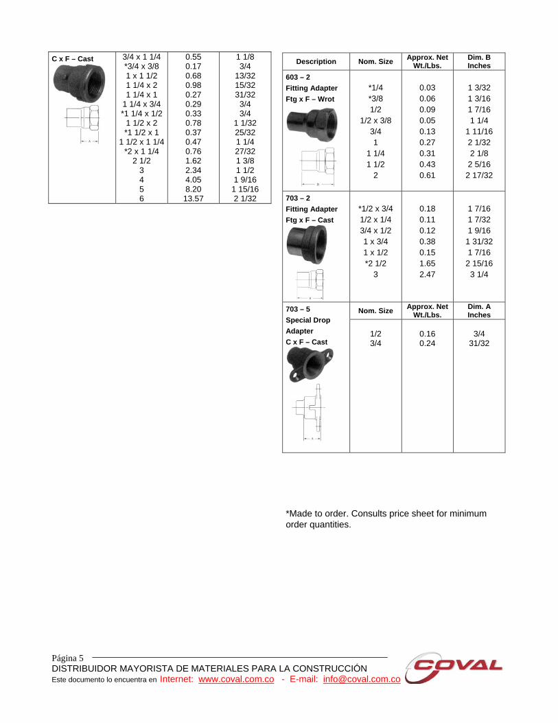
*Made to order. Consults price sheet for minimum order quantities.
Página 6 DISTRIBUIDOR MAYORISTA DE MATERIALES PARA LA CONSTRUCCIÓN Este documento lo encuentra en Internet: www.coval.com.co - E-mail: [email protected]
Description Nom. Size Approx. Net Wt./Lbs.
Dim. A Inches
703 – 5B Drop Adapter C x F – Cast
1/2
0.15
3/4
Nom. Size Approx. Net
Wt./Lbs. Dim. B Inches
604 Adapter C x M – Wrot
1/8 x 1/4 1/4 3/8
*3/8 x 3/4 3/8 x 1/2
1/2 1/2 x 1
1/2 x 3/4 1/2 x 3/8 1/2 x 1/4 5/8 x 3/4 5/8 x 1/2
3/4 3/4 x 1
3/4 x 1/2 1
1 x 1 1/2 1 x 1 1/4 1 x 3/4 1 x 1/2 1 1/4
1 1/4 x 1 ½ 1 1/4 x 1
1 1/2 1 1/2 x 2
1 1/2 x 1 ¼ 1 1/2 x 1
2 2 x 1 1/2
2 1/2 3
0.03 0.03 0.04 0.15 0.09 0.07 0.25 0.15 0.05 0.07 0.16 0.08 0.14 0.26 0.10 0.21 0.54 0.38 0.18 0.18 0.35 0.51 0.27 0.44 0.81 0.38 0.37 0.81 0.64 1.48 1.69
7/16 23/32 15/32 1 5/16
1 5/8
1 1/2 13/16 19/32 5/8
1 1/8 3/4
13/16 1 7/16 27/32 31/32 29/32 1 1/2 29/32 31/32 15/16
1 19/32 1 5/32 31/32 1 1/8
1 3/16 1 3/32 1 3/32 1 1/8
1 21/32 -
*Made to order. Consults price sheet for minimum order quantities.
Description Nom. Size Approx. Net Wt./Lbs.
Dim. B Inches
704 Adapter C x M – Cast
3/4 x 1 1/2 3/4 x 1 1/4 3/4 x 3/8
1 x 2 1 x 1 1/2 1 1/4 x 2
1 1/4 x 3/4 1 1/2 x 2 2 x 2 1/2 2 x 1 1/2 2 x 1 1/4
2 1/2 2 1/2 x 2
3 4 5 6
0.60 0.38 0.19 1.15 0.64 0.88 0.30 0.77 1.57 0.71 1.08 1.48 1.83 1.96 3.66 8.60
10.73
1 17/32 1 7/32 13/16
- 29/32 1 9/32 31/32 1 1/8
1 15/32 1 1/8
- 1 21/32 1 11/16 1 1/2
1 11/16 2 5/8
2 704-F Flush Adapter C x M – Cast
1/2 *3/4
0.03 0.03
9/16
19/32
Nom. Size Approx. Net Wt./Lbs.
Dim. A Inches
1/2
0.09
9/32
704 – H Hose Adapter C x Hose – Cast
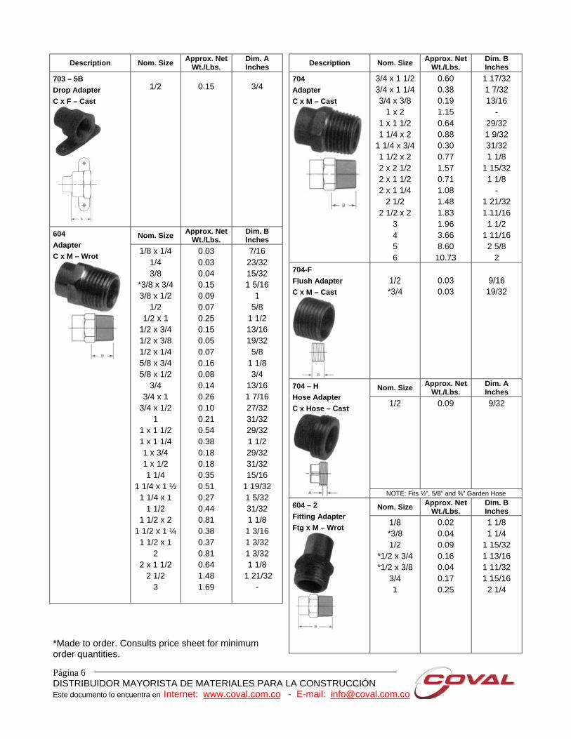
NOTE: Fits ½”, 5/8” and ¾” Garden Hose Nom. Size Approx. Net
Wt./Lbs. Dim. B Inches
604 – 2 Fitting Adapter Ftg x M – Wrot
1/8 *3/8 1/2
*1/2 x 3/4 *1/2 x 3/8
3/4 1
0.02 0.04 0.09 0.16 0.04 0.17 0.25
1 1/8 1 1/4
1 15/32 1 13/16 1 11/32 1 15/16 2 1/4
Página 7 DISTRIBUIDOR MAYORISTA DE MATERIALES PARA LA CONSTRUCCIÓN Este documento lo encuentra en Internet: www.coval.com.co - E-mail: [email protected]
Description Nom. Size Approx. Net Wt./Lbs.
Dim. B Inches
704 – 2 Fitting Adapter Ftg x M – Cast
3/4 x 1
3/4 x 1/2 1 x 3/4 1 1/4 1 1/2
2 2 1/2
3
0.27 0.12 0.24 0.43 0.54 0.89 1.55 2.21
1 31/32 1 23/32 1 15/16 2 27/32 2 13/32 2 3/4 3 3/8
3 23/32
Description Nom. Size Approx. Net Wt./Lbs.
Dim. B Inches
3/4 F x ½ H
0.16
1 5/8
704 – 2 – H Hose Adapter Ftg x Hose – Cast
NOTE: Fits ½”, 5/8” and ¾” Garden Hose.
AIR CHAMBERS Description Nom.
Size Approx.
Net Wt./Lbs.
Dim. A Inches
Dim. L Inches
0.21 0.41 0.78
1 1
1 1/8
619 Air Chamber Ftg. – Wrot
1/2 x 6
1/2 x 12 1/2 x 14 *3/4 x 12
0.40
6
12 14
1 12
Description Nom. Size Approx. Net Wt./Lbs.
Dim. L Inches
1/2 x 6 1/2 x 8
*1/2 x 10 1/2 x 12 *3/4 x 8
*3/4 x 12 *1 x 10 *1 x 15
0.14 0.19 0.24 0.28 0.31 0.46 0.55 0.82
6 8 10 12 8 12 10 15
620 – L Air Chamber or Stub – Out Ftg – Wrot
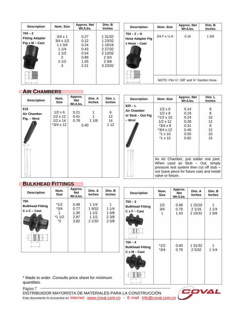
As Air Chamber, just solder one joint. When used as Stub – Out, simply pressure test system then cut off stub – out (save piece for future use) and install valve or fixture.
BULKHEAD FITTINGS Description Nom.
Size Approx.
Net Wt./Lbs.
Dim. A Inches
Dim. B Inches
750 Bulkhead Fitting C x C – Cast
*1/2 *3/4
1 *1 1/2
*2
0.48 0.77 1.30 2.87 3.82
1 1/4
1 9/32 1 1/2 1 1/2
2 1/32
1
1 1/4 1 5/8 2 3/8 2 5/8
* Made to order. Consults price sheet for minimum quantities.
Description Nom. Size
Approx. Net
Wt./Lbs. Dim. A Inches
Dim. B Inches
750 – 3 Bulkhead Fitting C x F – Cast
1/2 3/4 1
0.48 0.79 1.43
1 15/16 2 1/16
2 15/32
1
1 1/4 1 5/8
750 – 4 Bulkhead Fitting C x M – Cast
*1/2 *3/4
0.40 0.79
1 31/32 2 5/32
1
1 1/4

Página 8 DISTRIBUIDOR MAYORISTA DE MATERIALES PARA LA CONSTRUCCIÓN Este documento lo encuentra en Internet: www.coval.com.co - E-mail: [email protected]
BUSHINGS Description Nom. Size Approx. Net
Wt./Lbs. Dim. B Inches
718 – 3 Flush Bushing Ftg x F – Cast
*3/4 x 3/8
1 x 1/2 *1 1/4 x 3/4
1 1/2 x 1
0.06
0.13 0.18
0.25
1 31/32
31/32 1 1/32
1 5/32
618 – 3 Flush Bushing Ftg x F – Wrot
1/2 x 1/8 1/2 x 1/4
0.03 0.03
9/16 9/16
Description Nom. Size Approx. Net Wt./Lbs.
Dim. C Inches
618 Flush Bushing Ftg x C – Wrot
1/4 x 1/8 3/8 x 1/4 1/2 x 3/8 1/2 x 1/4 5/8 x 1/2 3/4 x 5/8 3/4 x 1/2 3/4 x 3/8 1 x 3/4 1 x 1/2
1 1/4 x 1 1 1/2 x 1 ¼ 2 x 1 1/2
0.01 0.01 0.02 0.04 0.03 0.22 0.08 0.11 0.12 0.22 0.17 0.22 0.66
1/16 1/16 3/32 1/4 1/16 3/16 3/32 7/16 1/8
15/32 3/32 5/32 1/8
CAPS Description Nom. Size Approx. Net
Wt./Lbs. Dim. N Inches
617 Tube Cap C – Wrot
1/8 1/4 3/8 1/2 5/8 3/4 1
1 1/4 1 1/2
2 2 1/2
3 4
0.01 0.01 0.01 0.02 0.03 0.04 0.07 0.10 0.16 0.27 0.50 0.78 1.66
1/32 3/32 3/32 3/32 1/8 1/8 5/32 3/32 1/8 5/32 7/32 7/32 1/4
*Made to order. Consult price sheet for minimum order quantities.
Description Nom. Size Approx. Net Wt./Lbs.
Dim. N Inches
717 Tube Cap C – Cast
5 6
5.48 9.07
7/16
17/32
Nom. Size Approx. Net Wt./Lbs.
Dim. A Inches
717 – D Drain Cap – Cast
*1/2 *3/4 *1
0.06 0.10 0.16
21/32 21/32 11/16
Página 9 DISTRIBUIDOR MAYORISTA DE MATERIALES PARA LA CONSTRUCCIÓN Este documento lo encuentra en Internet: www.coval.com.co - E-mail: [email protected]
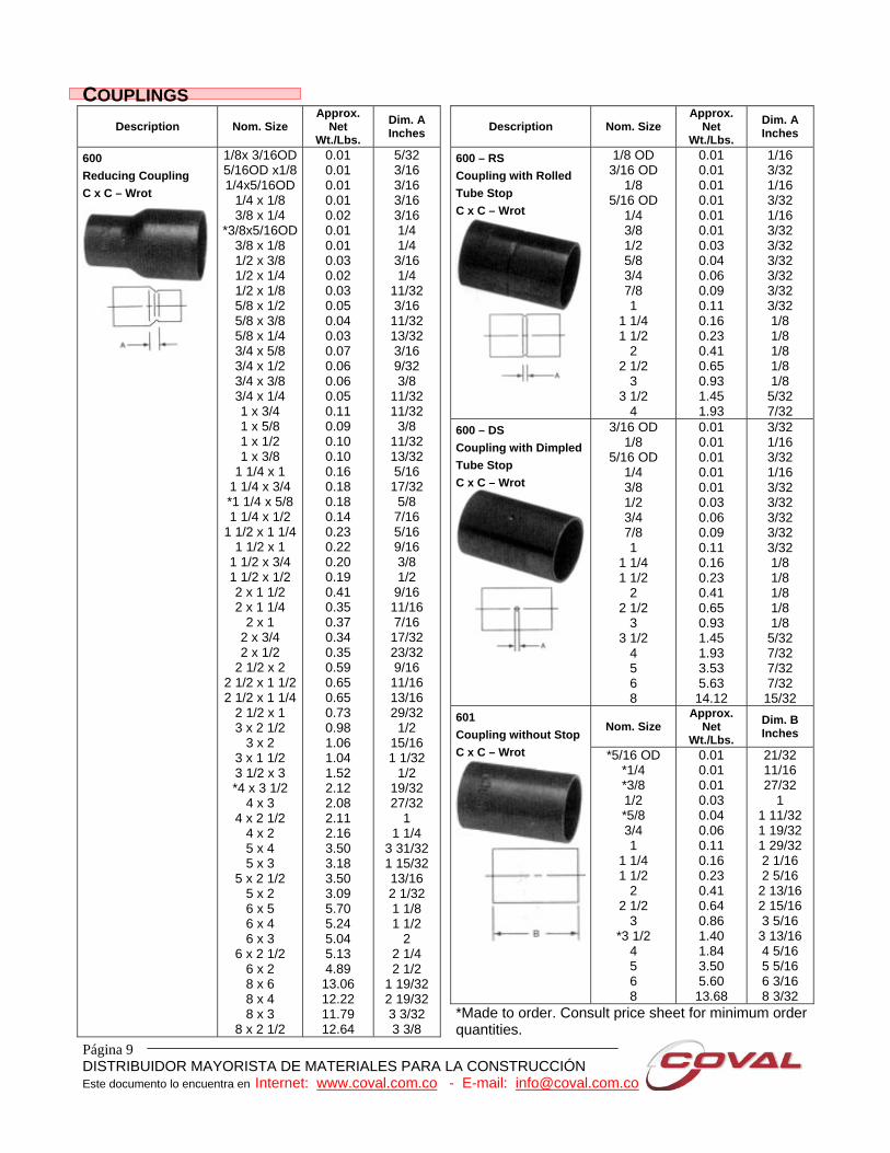
COUPLINGS Description Nom. Size
Approx. Net
Wt./Lbs.
Dim. A Inches
600 Reducing Coupling C x C – Wrot
1/8x 3/16OD 5/16OD x1/8 1/4x5/16OD
1/4 x 1/8 3/8 x 1/4
*3/8x5/16OD 3/8 x 1/8 1/2 x 3/8 1/2 x 1/4 1/2 x 1/8 5/8 x 1/2 5/8 x 3/8 5/8 x 1/4 3/4 x 5/8 3/4 x 1/2 3/4 x 3/8 3/4 x 1/4 1 x 3/4 1 x 5/8 1 x 1/2 1 x 3/8
1 1/4 x 1 1 1/4 x 3/4 *1 1/4 x 5/8 1 1/4 x 1/2
1 1/2 x 1 1/4 1 1/2 x 1
1 1/2 x 3/4 1 1/2 x 1/2 2 x 1 1/2 2 x 1 1/4
2 x 1 2 x 3/4 2 x 1/2
2 1/2 x 2 2 1/2 x 1 1/2 2 1/2 x 1 1/4
2 1/2 x 1 3 x 2 1/2
3 x 2 3 x 1 1/2 3 1/2 x 3 *4 x 3 1/2
4 x 3 4 x 2 1/2
4 x 2 5 x 4 5 x 3
5 x 2 1/2 5 x 2 6 x 5 6 x 4 6 x 3
6 x 2 1/2 6 x 2 8 x 6 8 x 4 8 x 3
8 x 2 1/2
0.01 0.01 0.01 0.01 0.02 0.01 0.01 0.03 0.02 0.03 0.05 0.04 0.03 0.07 0.06 0.06 0.05 0.11 0.09 0.10 0.10 0.16 0.18 0.18 0.14 0.23 0.22 0.20 0.19 0.41 0.35 0.37 0.34 0.35 0.59 0.65 0.65 0.73 0.98 1.06 1.04 1.52 2.12 2.08 2.11 2.16 3.50 3.18 3.50 3.09 5.70 5.24 5.04 5.13 4.89 13.06 12.22 11.79 12.64
5/32 3/16 3/16 3/16 3/16 1/4 1/4
3/16 1/4
11/32 3/16 11/32 13/32 3/16 9/32 3/8
11/32 11/32 3/8
11/32 13/32 5/16 17/32 5/8
7/16 5/16 9/16 3/8 1/2
9/16 11/16 7/16 17/32 23/32 9/16 11/16 13/16 29/32 1/2
15/16 1 1/32
1/2 19/32 27/32
1 1 1/4
3 31/32 1 15/32 13/16 2 1/32 1 1/8 1 1/2
2 2 1/4 2 1/2
1 19/32 2 19/32 3 3/32 3 3/8
Description Nom. Size Approx.
Net Wt./Lbs.
Dim. A Inches
600 – RS Coupling with Rolled Tube Stop C x C – Wrot
1/8 OD 3/16 OD
1/8 5/16 OD
1/4 3/8 1/2 5/8 3/4 7/8 1
1 1/4 1 1/2
2 2 1/2
3 3 1/2
4
0.01 0.01 0.01 0.01 0.01 0.01 0.03 0.04 0.06 0.09 0.11 0.16 0.23 0.41 0.65 0.93 1.45 1.93
1/16 3/32 1/16 3/32 1/16 3/32 3/32 3/32 3/32 3/32 3/32 1/8 1/8 1/8 1/8 1/8
5/32 7/32
600 – DS Coupling with Dimpled Tube Stop C x C – Wrot
3/16 OD 1/8
5/16 OD 1/4 3/8 1/2 3/4 7/8 1
1 1/4 1 1/2
2 2 1/2
3 3 1/2
4 5 6 8
0.01 0.01 0.01 0.01 0.01 0.03 0.06 0.09 0.11 0.16 0.23 0.41 0.65 0.93 1.45 1.93 3.53 5.63 14.12
3/32 1/16 3/32 1/16 3/32 3/32 3/32 3/32 3/32 1/8 1/8 1/8 1/8 1/8
5/32 7/32 7/32 7/32 15/32
Nom. Size Approx.
Net Wt./Lbs.
Dim. B Inches
601 Coupling without Stop C x C – Wrot *5/16 OD
*1/4 *3/8 1/2 *5/8 3/4 1
1 1/4 1 1/2
2 2 1/2
3 *3 1/2
4 5 6 8
0.01 0.01 0.01 0.03 0.04 0.06 0.11 0.16 0.23 0.41 0.64 0.86 1.40 1.84 3.50 5.60 13.68
21/32 11/16 27/32
1 1 11/32 1 19/32 1 29/32 2 1/16 2 5/16
2 13/16 2 15/16 3 5/16
3 13/16 4 5/16 5 5/16 6 3/16 8 3/32
*Made to order. Consult price sheet for minimum order quantities.
Página 10 DISTRIBUIDOR MAYORISTA DE MATERIALES PARA LA CONSTRUCCIÓN Este documento lo encuentra en Internet: www.coval.com.co - E-mail: [email protected]
Description Nom. Size Approx. Net Wt./Lbs.
Dim. A Inches
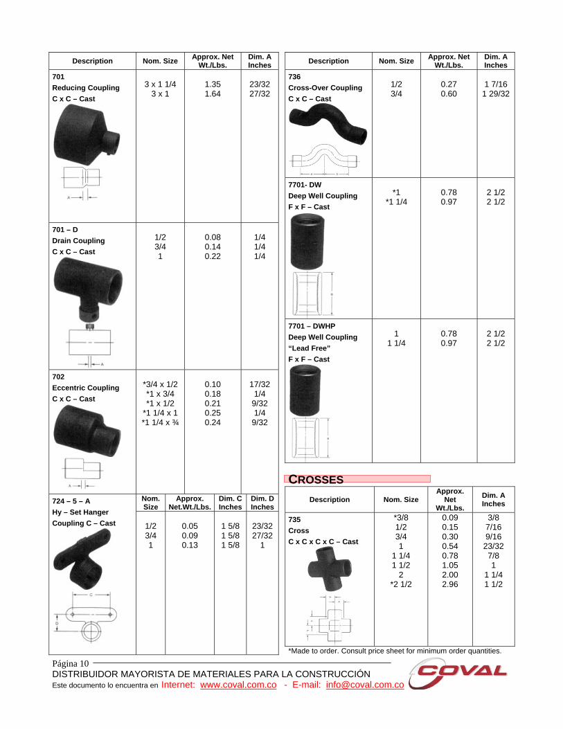
701 Reducing Coupling C x C – Cast
3 x 1 1/4
3 x 1
1.35 1.64
23/32 27/32
701 – D Drain Coupling C x C – Cast
1/2 3/4 1
0.08 0.14 0.22
1/4 1/4 1/4
702 Eccentric Coupling C x C – Cast
*3/4 x 1/2 *1 x 3/4 *1 x 1/2
*1 1/4 x 1 *1 1/4 x ¾
0.10 0.18 0.21 0.25 0.24
17/32 1/4
9/32 1/4
9/32
Nom. Size
Approx. Net.Wt./Lbs.
Dim. C Inches
Dim. D Inches
724 – 5 – A Hy – Set Hanger Coupling C – Cast
1/2 3/4 1
0.05 0.09 0.13
1 5/8 1 5/8 1 5/8
23/32 27/32
1
Description Nom. Size Approx. Net Wt./Lbs.
Dim. A Inches
736 Cross-Over Coupling C x C – Cast
1/2 3/4
0.27 0.60
1 7/16
1 29/32
7701- DW Deep Well Coupling F x F – Cast
*1
*1 1/4
0.78 0.97
2 1/2 2 1/2
7701 – DWHP Deep Well Coupling “Lead Free” F x F – Cast
1
1 1/4
0.78 0.97
2 1/2 2 1/2
CROSSES
Description Nom. Size Approx.
Net Wt./Lbs.
Dim. A Inches
735 Cross C x C x C x C – Cast
*3/8 1/2 3/4 1
1 1/4 1 1/2
2 *2 1/2
0.09 0.15 0.30 0.54 0.78 1.05 2.00 2.96
3/8 7/16 9/16
23/32 7/8 1
1 1/4 1 1/2
*Made to order. Consult price sheet for minimum order quantities.
Página 11 DISTRIBUIDOR MAYORISTA DE MATERIALES PARA LA CONSTRUCCIÓN Este documento lo encuentra en Internet: www.coval.com.co - E-mail: [email protected]
ELBOWS
Description Nom. Size
Approx. Net
Wt./Lbs.
Dim. C Inches
Dim. D Inches
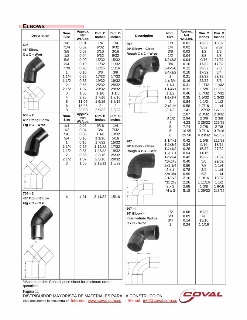
606 45° Elbow C x C – Wrot
1/8 *1/4 3/8 1/2 5/8 3/4 *7/8
1 1 1/4 1 1/2
2 2 1/2
3 4 5 6 8
0.01 0.02 0.03 0.04 0.09 0.10 0.20 0.16 0.25 0.35 0.65 1.07 1.58 3.35
11.05 16.95 23.00
1/4 9/32 3/16 9/32
15/32 11/32 11/16 3/8
17/32 19/32 25/32 29/32 1 1/8
1 7/16 1 9/16
2 2 9/32
1/4 9/32 3/16 9/32
15/32 11/32 11/16 3/8
17/32 19/32 25/32 29/32 1 1/8
1 7/161 9/16
2 2 9/32
Nom. Size
Approx. Net
Wt./Lbs.
Dim. B Inches
Dim. C Inches
606 – 2 45° Fitting Elbow Ftg x C – Wrot
1/4 1/2 5/8 3/4 1
1 1/4 1 1/2
2 2 1/2
3
0.02 0.04 0.08 0.10 0.16 0.25 0.35 0.65 1.07 1.55
9/16 3/4
1 1/8 1 1/16 1 7/32 1 19/32 1 25/32 2 3/16 2 3/16 2 19/32
1/4 7/32
13/32 5/16
15/32 17/32 19/32 25/32 29/32 1 5/32
706 – 2 45° Fitting Elbow Ftg x C – Cast
4
4.31
3 11/32
15/16
*Made to order. Consult price sheet for minimum order quantities.
Description Nom. Size
Approx. Net
Wt./Lbs.
Dim. C Inches
Dim. D Inches
607 90° Elbow – Close Rough C x C – Wrot
1/8 1/4 3/8 1/2
1/2x3/8 3/4
3/4x5/8 3/4x1/2
1 1 x 3/4 1 1/4
1 1/4x1 1 1/2
1½x1¼ 2
2 x1 ½ 2 1/2
3 3 1/2
4 5 6 8
0.01 0.02 0.03 0.04 0.04 0.10 0.12 0.10 0.21 0.16 0.31 0.31 0.46 0.35 0.84 0.58 1.41 2.07 2.94 4.23 7.74
10.95 29.50
13/32 9/32 1/2 3/8 9/16
17/32 29/32 17/32 23/32 23/32 1 1/32 1 5/8
1 7/32 1 5/32 1 1/2
1 7/16 1 27/32 2 3/32 2 3/8
2 25/32 2 7/8
3 7/16 4 23/32
13/32 9/32 1/2 3/8
21/32 17/32 7/8 3/4
23/32 5/8
1 1/32115/321 7/321 3/321 1/2 1 1/4
127/322 3/322 3/8
225/322 7/8
3 7/16423/32
707 90° Elbow – Close Rough C x C – Cast
1 1/4x1 1¼x3/4 1¼x1/2 1 ½ x 1 1½x3/4 *1½x½ 2x1 1/4 2 x 1
*2x 3/4 2 1/2x2 *3x 2½ 3 x 2 *4 x 3
0.42 0.34 0.28 0.54 0.42 0.40 0.86 0.78 0.69 2.16 2.26 2.68 5.18
1 5/8 9/16
15/32 11/16 19/32 5/8 7/8 3/4 5/8
1 3/16 1 11/16 1 3/8
1 29/32
115/3213/16 27/32
1 31/32 29/32 1 1/4 1 1/4 1 1/4 19/32 1 1/2
1 9/16215/32
607 – I 90° Elbow – Intermediate Radius C x C – Wrot
1/2 5/8 3/4 1
0.06 0.09 0.14 0.24
19/32 7/8
13/16 1 1/16

Página 12 DISTRIBUIDOR MAYORISTA DE MATERIALES PARA LA CONSTRUCCIÓN Este documento lo encuentra en Internet: www.coval.com.co - E-mail: [email protected]
Description Nom. Size
Approx. Net
Wt./Lbs.
Dim. C Inches
Dim. D Inches
607 – LT 90° Elbow – Long Radius C x C – Wrot
3/16OD 1/8
5/16OD 1/4
1/4x1/8 3/8 1/2
1/2x3/8 1/2x1/4
5/8 5/8x1/2
3/4 3/4x5/8 3/4x1/2
7/8 1
1 x 3/4 *1 x 5/8 *1 x 1/2
1 1/4 *1 ¼ x1
1 1/2 *1½x1¼
2 2 1/2
3 4
0.01 0.01 0.02 0.02 0.01 0.04 0.08 0.06 0.03 0.10 0.09 0.16 0.13 0.10 0.28 0.28 0.20 0.15 0.13 0.42 0.33 0.66 0.49 1.23 1.96 2.93 5.95
13/32 13/32 9/16
17/32 19/32 23/32 7/8
13/16 25/32 1 3/32 1 1/16 1 1/8 1 1/4 1 1/8
1 19/321 7/16 1 1/4
1 13/321 9/32 1 7/8
1 25/322 1/4 2 1/4
2 15/163 11/164 1/32 5 1/4
13/32 13/32 9/16
17/32 1/2
23/32 7/8
13/16 21/32 1 3/321 1/161 1/8
1 3/321 1/16119/321 7/161 1/8
1 3/321 1/161 7/8 1 1/2 2 1/4
2 3/32215/16311/164 1/325 1/4
Nom. Size
Approx. Net
Wt./Lbs.
Dim. B Inches
Dim. C Inches
607 – 2 90° Fitting Elbow – Close Rough Ftg x C – Wrot
1/4 3/8 1/2 5/8 3/4 1
1 1/4 1 1/2
2 2 1/2
3 4
0.02 0.03 0.04 0.07 0.10 0.20 0.33 0.46 0.84 1.39 2.10 4.00
3/4 15/16 31/32 1 7/32 1 11/321 3/4 2 1/8
2 13/322 27/323 15/323 13/164 3/4
3/8 1/2 3/8
17/32 17/32 27/32 1 1/321 7/321 1/2
129/322 3/32225/32
*Made to order. Consult price sheet for minimum order quantities.
Description Nom. Size
Approx. Net
Wt./Lbs.
Dim. B Inches
Dim. C Inches
607 – 2 – I 90° Fitting Elbow – Intermediate Radius Ftg x C
1/2 5/8 3/4 1
0.06 0.09 0.14 0.24
1 5/32 1 9/16 1 5/8
2 1/32
19/32 7/8
13/16 1 1/16
607 – 2 – LT 90° Fitting Elbow – Long Radius Ftg x C – Wrot
*1/8 1/4 3/8
*3/8x1/2 1/2
*1/2x3/8 *1/2x1/4
5/8 3/4 1
1 1/4 1 1/2
*1½x1¼ 2
2 1/2 3
0.01 0.02 0.05 0.06 0.08 0.06 0.03 0.10 0.16 0.31 0.43 0.66 0.50 1.27 2.16 3.10
13/32 1 1/8 1 1/8 1 1/8
1 9/16 1 5/16 1 1/4
1 25/321 15/162 1/2
2 29/322 13/323 3/8
4 11/325 7/32 5 3/4
1/2 3/4 7/8
29/32 1 3/3213/16 5/8
1 3/321 1/8
1 21/321 7/8 2 1/4
2 3/322 31/32311/164 1/32
Nom. Size Approx.
Net Wt./Lbs.
Dim. B Inches
607 – 2 – 2 90° Fitting Elbow – Close Rough Ftg x Ftg – Wrot
1/2 ¾ 1
*1 1/4 1 1/2
*2 3
0.04 0.12 0.20 0.33 0.46 0.82 2.12
1 1/16 1 15/32 1 23/32 2 1/8
2 13/32 2 27/32 3 7/8
607 – 2 – 2 – LT 90° Fitting Elbow – Long Radius Ftg x Ftg – Wrot
*1/8 1/4 3/8 1/2 5/8 3/4 1
1 1/4 1 1/2
2
0.01 0.02 0.04 0.08 0.10 0.16 0.31 0.43 0.65 1.25
11/16 27/32 1 1/8
1 19/32 1 11/16 1 15/16 2 1/2
2 29/32 3 7/16
4 11/32

Página 13 DISTRIBUIDOR MAYORISTA DE MATERIALES PARA LA CONSTRUCCIÓN Este documento lo encuentra en Internet: www.coval.com.co - E-mail: [email protected]
Description Nom. Size
Approx. Net
Wt./Lbs.
Dim. C Inches
Dim. E Inches
707 – 3 90° Elbow C x F – Cast
*1/4 *3/8
*3/8x1/21/2
1/2x3/4 1/2 x3/8 *1/2x1/4
3/4 3/4 x 1 3/4x1/2
1 1 x 3/4 1 x 1/2 1 1/4
*1 1/4x1*1¼ x ¾
1 1/2 2
0.06 0.09 0.13 0.12 0.18 0.09 0.10 0.18 0.35 0.20 0.43 0.35 0.26 0.67 0.53 0.47 0.89 1.46
13/32 7/16 9/16 7/16
11/16 1/2 3/8
21/32 13/16 9/16
25/32 11/16 9/16
1 13/16 9/16 1 1/8 1 3/8
9/16 11/16 13/16 13/16 15/16 13/16 23/32 15/16 1 1/8 15/16 1 1/4
1 3/161 1/8 1 1/2
1 7/161 11/161 5/8
1 15/16
Nom. Size
Approx. Net
Wt./Lbs.
Dim. B Inches
Dim. E Inches
707 – 2 – 4 90° Fitting Elbow Ftg x M – Cast
*1/2 *3/4 *1
0.12 0.22 0.40
7/8 1 7/16 1 27/32
25/32 1 11/321 19/32
Nom. Size
Approx. Net
Wt./Lbs.
Dim. C Inches
Dim. E Inches
707 – 3 – 5 – A 90° Hy – Set Elbow C x F – Cast
1/2
0.21
9/16
7/8
707 – 3 – 5 90° Drop Elbow C x F – Cast
Nom. Size Approx.
Net Wt./Lbs.
Dim. A Inches
Dim. C Inches
Dim. E Inches
*3/8 *3/8 x 1/2
1/2 1/2 x 3/8
3/4 3/4 x 1/2
1
0.12 0.18 0.15 0.17 0.28 0.24 0.49
11/32 11/32 13/32 3/8
17/32 17/32 5/8
7/16 9/16 9/16 1/2
21/32 9/16
25/32
11/16 13/16 7/8
13/16 15/16 15/16 1 ¼
Description Nom. Size
Approx. Net
Wt./Lbs.
Dim. A Inches
Dim. E Inches
707 – 3 –6 90° Union Elbow C x F – Cast
*1/2 3/4 *1
0.31 0.49 0.79
1 1/8
1 7/16 1 7/8
7/8 1
1 1/4
Nom. Size
Approx. Net
Wt./Lbs.
Dim. C Inches
Dim. E Inches
707 – 4 90° Elbow C x M – Cast
*3/8 1/2
1/2 x3/4 *½ x 3/8
3/4 *3/4 x 1 3/4x 1/2
1 1 1/4 1 1/2
2
0.08 0.12 0.18 0.10 0.21 0.33 0.18 0.43 0.58 0.81 1.38
5/16 7/16 9/16 5/16 9/16
21/32 7/16
23/32 7/8 1
1 1/4
7/8 1 5/321 5/3215/16 1 11/321 13/321 7/321 5/8
1 11/161 31/322 9/32
Nom. Size
Approx. Net
Wt./Lbs.
Dim. A Inches
Dim. E Inches
707 – 4 – 6 90° Union Elbow C x M – Cast
3/8 1/2 3/4 1
*1 1/4 *1 1/2
*2
0.21 0.30 0.49 0.72 1.16 1.59 2.98
1 3/32 1 1/32 1 5/16 1 23/321 3/4
2 3/16 2 21/32
1 3/161 1/2
1 13/161 5/8
1 27/322 3/162 1/2
*Made to order. Consult price sheet for minimum order quantities.
Página 14 DISTRIBUIDOR MAYORISTA DE MATERIALES PARA LA CONSTRUCCIÓN Este documento lo encuentra en Internet: www.coval.com.co - E-mail: [email protected]
Description Nom. Size
Approx. Net
Wt./Lbs.
Dim. A Inches
Dim. C Inches
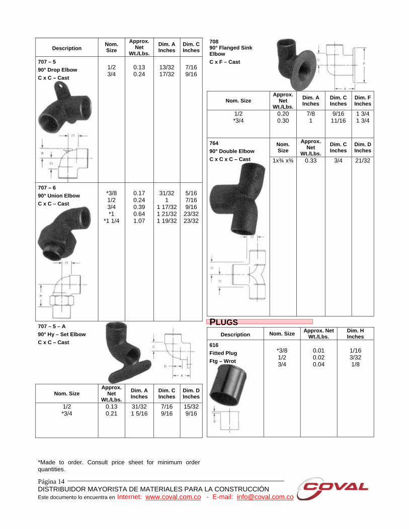
707 – 5 90° Drop Elbow C x C – Cast
1/2 3/4
0.13 0.24
13/32 17/32
7/16 9/16
707 – 6 90° Union Elbow C x C – Cast
*3/8 1/2 3/4 *1
*1 1/4
0.17 0.24 0.39 0.64 1.07
31/32
1 1 17/321 21/321 19/32
5/16 7/16 9/16
23/32 23/32
707 – 5 – A 90° Hy – Set Elbow C x C – Cast
Nom. Size Approx.
Net Wt./Lbs.
Dim. A Inches
Dim. C Inches
Dim. D Inches
1/2 *3/4
0.13 0.21
31/32 1 5/16
7/16 9/16
15/32 9/16
708 90° Flanged Sink Elbow C x F – Cast
Nom. Size Approx.
Net Wt./Lbs.
Dim. A Inches
Dim. C Inches
Dim. F Inches
1/2 *3/4
0.20 0.30
7/8 1
9/16 11/16
1 3/4 1 3/4
Nom. Size
Approx. Net
Wt./Lbs.
Dim. C Inches
Dim. D Inches
764 90° Double Elbow C x C x C – Cast
1x¾ x¾
0.33
3/4
21/32
PLUGS Description Nom. Size Approx. Net
Wt./Lbs. Dim. H Inches
616 Fitted Plug Ftg – Wrot
*3/8 1/2 3/4
0.01 0.02 0.04
1/16 3/32 1/8
*Made to order. Consult price sheet for minimum order quantities.

Página 15 DISTRIBUIDOR MAYORISTA DE MATERIALES PARA LA CONSTRUCCIÓN Este documento lo encuentra en Internet: www.coval.com.co - E-mail: [email protected]
FITTING REDUCERS FLANGES CLASS 125
Description Nom. Size Approx.
Net Wt./Lbs.
Dim. B Inches
600 – 2 Fitting Reducer Ftg x C – Wrot
1/4 x 1/8 3/8 x 1/4 3/8 x 1/8 1/2 x 3/8 1/2 x 1/4 5/8 x 1/2 5/8 x 3/8 *5/8 x 1/4 3/4 x 5/8 3/4 x 1/2 3/4 x 3/8 *3/4 x 1/4
1 x 3/4 1 x 5/8 1 x 1/2 *1 x 3/8 1 1/4 x 1
1 1/4 x 3/4 1 1/4 x 1/2 1 1/2x1 1/4
1 1/2 x 1 1 1/2 x 3/4 1 1/2 x 1/2 2 x 1 1/2 2 x 1 1/4
2 x 1 2 x 3/4 2 x 1/2
2 1/2 x 2 2 1/2x1 1/2 2 1/2x1 1/4
2 1/2 x 1 3 x 2 1/2
3 x 2 3 x 1 1/2 3 x 1 1/4 3 1/2 x 3 4 x 3 1/2
4 x 3 4 x 2 1/2
4 x 2 5 x 4 5 x 3
5 x 2 1/2 5 x 2 6 x 5 6 x 4 6 x 3
6 x 2 1/2 6 x 2 8 x 6 8 x 5 8 x 4 8 x 3
8 x 2 1/2 8 x 2
0.01 0.01 0.01 0.03 0.02 0.04 0.04 0.03 0.06 0.06 0.05 0.05 0.10 0.09 0.09 0.08 0.15 0.16 0.13 0.23 0.21 0.20 0.16 0.40 0.34 0.35 0.35 0.34 0.65 0.65 0.60 0.78 1.03 0.99 1.06 1.29 1.48 2.09 2.00 1.95 1.95 3.30 2.97 3.30 2.88 5.56 5.09 4.67 4.47 4.51 12.33 10.35 11.10 10.63 11.41 10.86
15/32 19/32 25/32 11/16 25/32 7/8
31/32 1 1/32 31/32 1 1/8 1 1/8 1 3/32 1 7/32 1 3/8 1 1/4 1 9/32 1 5/16 1 1/2 1 3/8
1 13/32 1 5/8 1 7/8
1 19/32 1 31/32 2 3/32
1 27/32 1 27/32 1 31/32 1 31/32 2 3/8 2 7/32 2 9/32 2 1/4 2 9/16
2 19/32 3 1/4
2 11/32 2 5/8 3 1/32 3 1/32
3 13/32 3 9/16 4 1/16
4 11/32 4 11/16 4 3/16 4 9/16 5 1/16
5 11/32 5 19/32 5 15/32 5 15/16 6 7/16
6 15/16 7 3/16 7 7/16
Description Nom. Size
Approx. Net
Wt./Lbs. Dim. B Inches
Dim. F Inches
Dim. W
Inches741 Companion Flange C – Cast
*1/2 *3/4
1 1 ¼ 1 ½
2 2 ½
3 4 5 6 8
0.49 0.71 0.99 1.14 1.76 2.76 3.65 4.81 6.46 9.04
12.68 24.50
1/8 1/8 1/8 1/8 1/8 1/8 1/8 1/8 1/8 1/8 1/8 1/8
3 1/2 3 7/8 4 1/4 4 5/8
5 6 7
7 1/2 9
10 11
13 1/2
2 3/8 2 3/4 3 1/8 3 1/2 3 7/8 4 3/4 5 1/2
6 7 1/2 8 1/2 9 1/2
11 3/4
FLANGES CLASS 150
Description Nom. Size
Approx. Net
Wt./Lbs. Dim. B Inches
Dim. F Inches
Dim. W
Inches771 Companion Flange C – Cast
*3/4 1
1 ¼ 1 ½ 2
2 ½ 3 4 5 6
1.15 1.59 1.91 2.43 3.67 5.78 7.22
10.35 15.69 17.91
1/8 1/8 1/8 1/8 1/8 1/8 1/8 1/8 1/8 1/8
3 7/8 4 1/4 4 5/8
5 6 7
7 1/2 9
10 11
2 3/4 3 1/8 3 1/2 3 7/8 4 3/4 5 1/2
6 7 1/2 8 1/2 9 1/2
775 Threaded Companion Flange F – Cast
*2
2 ½ 3 4
4.31 6.30 7.13
10.20
1
1 1/8 1 3/16 1 5/16
6 7
7 1/2 9
4 3/4 5 1/2
6 7 1/2
*Made to order. Consult price sheet for minimum order quantities.
Página 16 DISTRIBUIDOR MAYORISTA DE MATERIALES PARA LA CONSTRUCCIÓN Este documento lo encuentra en Internet: www.coval.com.co - E-mail: [email protected]
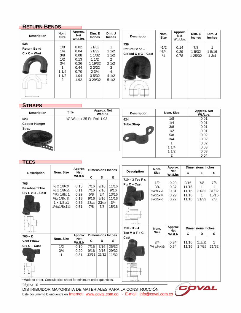
RETURN BENDS
Description Nom. Size
Approx. Net
Wt./Lbs. Dim. E Inches
Dim. J Inches
638 Return Bend C x C – Wrot
1/8 1/4 3/8 1/2 3/4 1
1 1/4 1 1/2
2
0.02 0.04 0.08 0.13 0.26 0.44 0.70 1.04 1.92
21/32 21/32 1 1/32 1 1/2
1 19/32 2 3/32 2 3/4
3 5/32 3 29/32
1
1 1/2 1 1/2
2 2 1/2
3 4
4 1/2 5 1/2
Description Nom. Size
Approx. Net
Wt./Lbs. Dim. E Inches
Dim. J Inches
739 Return Bend – Closed C x C – Cast
*1/2 *3/4 *1
0.14 0.29 0.78
7/8
1 5/32 1 25/32
1
1 5/16 1 3/4
STRAPS Description Size Approx. Net
Wt./Lbs. 623 Copper Hanger Strap
¾” Wide x 25 Ft. Roll 1.93
Description Nom. Size Approx. Net Wt./Lbs.
624 Tube Strap
1/8 1/4 3/8 1/2 5/8 3/4 1
1 1/4 1 1/2
2
0.01 0.01 0.01 0.01 0.02 0.02 0.02 0.03 0.03 0.04
TEES Dimensions Inches
Description Nom. Size Approx
Net Wt./Lb C D E
705 Baseboard Tee C x F x C – Cast
½ x 1/8x¾ ½ x 1/8x½ *¾x 1/8x 1 ¾x 1/8x ¾ 1 x 1/8 x1
1¼x1/8x1¼
0.15 0.11 0.29 0.19 0.32 0.51
7/16 7/16 5/8 9/16 23/32 7/8
9/167/163/4 9/1623/327/8
11/169/16 13/1611/163/4
15/16
Dimensions Inches Nom. Size
Approx Net
Wt./Lb C D S 705 – D Vent Elbow C x C – Cast
1/2 3/4 1
0.10 0.20 0.31
7/169/16 23/32
7/169/1623/32
25/3229/3211/32
*Made to order. Consult price sheet for minimum order quantities.
Dimensions Inches Description
Nom. Size
Approx Net
Wt./Lbs C E S
710 – 3 Tee F x F x C – Cast
1/2 3/4
¾x¾x½ ¾x½x¾ ¾x½x½
0.20 0.37 0.31 0.29 0.27
9/16 11/16 11/16 11/16 11/16
7/8 1
31/321
31/32
7/8 1
31/3215/167/8
Dimensions Inches Nom. Size
Approx Net
Wt./Lb C D S
710 – 3 – 4 Tee M x F x C – Cast
3/4
*¾ x¾x½
0.34 0.34
11/16 11/16
111/321 7/32
1
31/32
Página 17 DISTRIBUIDOR MAYORISTA DE MATERIALES PARA LA CONSTRUCCIÓN Este documento lo encuentra en Internet: www.coval.com.co - E-mail: [email protected]
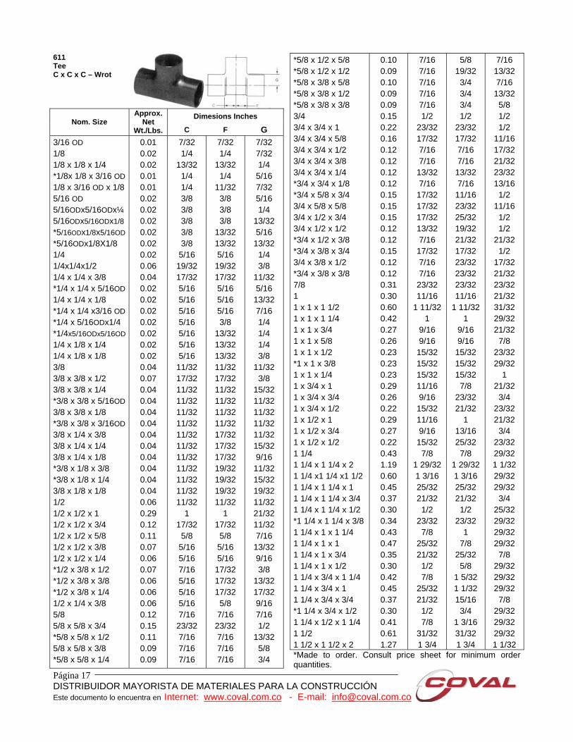
611 Tee C x C x C – Wrot
Dimesions Inches Nom. Size
Approx. Net
Wt./Lbs. C F G 3/16 OD 1/8 1/8 x 1/8 x 1/4 *1/8x 1/8 x 3/16 OD 1/8 x 3/16 OD x 1/8 5/16 OD 5/16ODx5/16ODx¼ 5/16ODx5/16ODx1/8 *5/16ODx1/8x5/16OD *5/16ODx1/8X1/8 1/4 1/4x1/4x1/2 1/4 x 1/4 x 3/8 *1/4 x 1/4 x 5/16OD 1/4 x 1/4 x 1/8 *1/4 x 1/4 x3/16 OD *1/4 x 5/16ODx1/4 *1/4x5/16ODx5/16OD 1/4 x 1/8 x 1/4 1/4 x 1/8 x 1/8 3/8 3/8 x 3/8 x 1/2 3/8 x 3/8 x 1/4 *3/8 x 3/8 x 5/16OD 3/8 x 3/8 x 1/8 *3/8 x 3/8 x 3/16OD 3/8 x 1/4 x 3/8 3/8 x 1/4 x 1/4 3/8 x 1/4 x 1/8 *3/8 x 1/8 x 3/8 *3/8 x 1/8 x 1/4 3/8 x 1/8 x 1/8 1/2 1/2 x 1/2 x 1 1/2 x 1/2 x 3/4 1/2 x 1/2 x 5/8 1/2 x 1/2 x 3/8 1/2 x 1/2 x 1/4 *1/2 x 3/8 x 1/2 *1/2 x 3/8 x 3/8 *1/2 x 3/8 x 1/4 1/2 x 1/4 x 3/8 5/8 5/8 x 5/8 x 3/4 *5/8 x 5/8 x 1/2 5/8 x 5/8 x 3/8 *5/8 x 5/8 x 1/4
0.01 0.02 0.02 0.01 0.01 0.02 0.02 0.02 0.02 0.02 0.02 0.06 0.04 0.02 0.02 0.02 0.02 0.02 0.02 0.02 0.04 0.07 0.04 0.04 0.04 0.04 0.04 0.04 0.04 0.04 0.04 0.04 0.06 0.29 0.12 0.11 0.07 0.06 0.07 0.06 0.06 0.06 0.12 0.15 0.11 0.09 0.09
7/32 1/4
13/32 1/4 1/4 3/8 3/8 3/8 3/8 3/8 5/16
19/32 17/32 5/16 5/16 5/16 5/16 5/16 5/16 5/16
11/32 17/32 11/32 11/32 11/32 11/32 11/32 11/32 11/32 11/32 11/32 11/32 11/32
1 17/32 5/8 5/16 5/16 7/16 5/16 5/16 5/16 7/16
23/32 7/16 7/16 7/16
7/32 1/4
13/32 1/4
11/32 3/8 3/8 3/8
13/32 13/32 5/16
19/32 17/32 5/16 5/16 5/16 3/8
13/32 13/32 13/32 11/32 17/32 11/32 11/32 11/32 11/32 17/32 17/32 17/32 19/32 19/32 19/32 11/32
1 17/32 5/8 5/16 5/16
17/32 17/32 17/32 5/8 7/16
23/32 7/16 7/16 7/16
7/32 7/32 1/4 5/16 7/32 5/16 1/4
13/32 5/16
13/32 1/4 3/8
11/32 5/16
13/32 7/16 1/4 1/4 1/4 3/8
11/32 3/8
15/32 11/32 11/32 11/32 11/32 15/32 9/16
11/32 15/32 19/32 11/32 21/32 11/32 7/16
13/32 9/16 3/8
13/32 17/32 9/16 7/16 1/2
13/32 5/8 3/4
*5/8 x 1/2 x 5/8 *5/8 x 1/2 x 1/2 *5/8 x 3/8 x 5/8 *5/8 x 3/8 x 1/2 *5/8 x 3/8 x 3/8 3/4 3/4 x 3/4 x 1 3/4 x 3/4 x 5/8 3/4 x 3/4 x 1/2 3/4 x 3/4 x 3/8 3/4 x 3/4 x 1/4 *3/4 x 3/4 x 1/8 *3/4 x 5/8 x 3/4 3/4 x 5/8 x 5/8 3/4 x 1/2 x 3/4 3/4 x 1/2 x 1/2 *3/4 x 1/2 x 3/8 *3/4 x 3/8 x 3/4 3/4 x 3/8 x 1/2 *3/4 x 3/8 x 3/8 7/8 1 1 x 1 x 1 1/2 1 x 1 x 1 1/4 1 x 1 x 3/4 1 x 1 x 5/8 1 x 1 x 1/2 *1 x 1 x 3/8 1 x 1 x 1/4 1 x 3/4 x 1 1 x 3/4 x 3/4 1 x 3/4 x 1/2 1 x 1/2 x 1 1 x 1/2 x 3/4 1 x 1/2 x 1/2 1 1/4 1 1/4 x 1 1/4 x 2 1 1/4 x1 1/4 x1 1/2 1 1/4 x 1 1/4 x 1 1 1/4 x 1 1/4 x 3/4 1 1/4 x 1 1/4 x 1/2 *1 1/4 x 1 1/4 x 3/8 1 1/4 x 1 x 1 1/4 1 1/4 x 1 x 1 1 1/4 x 1 x 3/4 1 1/4 x 1 x 1/2 1 1/4 x 3/4 x 1 1/4 1 1/4 x 3/4 x 1 1 1/4 x 3/4 x 3/4 *1 1/4 x 3/4 x 1/2 1 1/4 x 1/2 x 1 1/4 1 1/2 1 1/2 x 1 1/2 x 2
0.10 0.09 0.10 0.09 0.09 0.15 0.22 0.16 0.12 0.12 0.12 0.12 0.15 0.15 0.15 0.12 0.12 0.15 0.12 0.12 0.31 0.30 0.60 0.42 0.27 0.26 0.23 0.23 0.23 0.29 0.26 0.22 0.29 0.27 0.22 0.43 1.19 0.60 0.45 0.37 0.30 0.34 0.43 0.47 0.35 0.30 0.42 0.45 0.37 0.30 0.41 0.61 1.27
7/16 7/16 7/16 7/16 7/16 1/2
23/32 17/32 7/16 7/16
13/32 7/16
17/32 17/32 17/32 13/32 7/16
17/32 7/16 7/16
23/32 11/16
1 11/32 1
9/16 9/16
15/32 15/32 15/32 11/16 9/16
15/32 11/16 9/16
15/32 7/8
1 29/32 1 3/16 25/32 21/32 1/2
23/32 7/8
25/32 21/32 1/2 7/8
25/32 21/32 1/2 7/8
31/32 1 3/4
5/8 19/32 3/4 3/4 3/4 1/2
23/32 17/32 7/16 7/16
13/32 7/16
11/16 23/32 25/32 19/32 21/32 17/32 23/32 23/32 23/32 11/16
1 11/32 1
9/16 9/16
15/32 15/32 15/32 7/8
23/32 21/32
1 13/16 25/32 7/8
1 29/32 1 3/16 25/32 21/32 1/2
23/32 1
7/8 25/32 5/8
1 5/32 1 1/32 15/16 3/4
1 3/16 31/32 1 3/4
7/16 13/32 7/16
13/32 5/8 1/2 1/2
11/16 17/32 21/32 23/32 13/16 1/2
11/16 1/2 1/2
21/32 1/2
17/32 21/32 23/32 21/32 31/32 29/32 21/32 7/8
23/32 29/32
1 21/32 3/4
23/32 21/32 3/4
23/32 29/32 1 1/32 29/32 29/32 3/4
25/32 29/32 29/32 29/32 7/8
29/32 29/32 29/32 7/8
29/32 29/32 29/32 1 1/32
*Made to order. Consult price sheet for minimum order quantities.

Página 18 DISTRIBUIDOR MAYORISTA DE MATERIALES PARA LA CONSTRUCCIÓN Este documento lo encuentra en Internet: www.coval.com.co - E-mail: [email protected]
Dimesions Inches Nom. Size
Approx. Net
Wt./Lbs. C F G 1 1/2 x1 1/2 x1 1/4 1 1/2 x 1 1/2 x 1 1 1/2 x 1 1/2 x 3/4 1 1/2 x 1 1/2 x 1/2 1 1/2 x 1 1/4 x 1 ½ 1 1/2 x 1 1/4 x 1 ¼ 1 1/2 x 1 1/4 x 1 1 1/2 x 1 1/4 x 3/4 1 1/2 x 1 1/4 x 1/2 1 1/2 x 1 x 1 1/2 1 1/2 x 1 x 1 1/4 1 1/2 x 1 x 1 1 1/2 x 1 x 3/4 1 1/2 x 1 x 1/2 1 1/2 x 3/4 x 1 1/2 *1 1/2 x 3/4 x 1 1/4 1 1/2 x 3/4 x 1 1 1/2 x 3/4 x 3/4 *1 1/2 x 3/4 x 1/2 1 1/2 x 1/2 x 1 1/2 2 2 x 2 x 2 1/2 2 x 2 x 1 1/2 2 x 2 x 1 1/4 2 x 2 x 1 2 x 2 x 3/4 2 x 2 x 1/2 2 x 1 1/2 x 2 2 x 1 1/2 x 1 1/2 2 x 1 1/2 x 1 1/4 2 x 1 1/2 x 3/4 2 x 1 1/2 x 1/2 2 x 1 1/4 x 2 2 x 1 1/4 x 1 1/2 2 x 1 1/4 x 1 1/4 2 x 1 1/4 x 1 *2 x 1 1/4 x 3/4 2 x 1 x 2 2 x 1 x 1 2 x 3/4 x 2 2 x 1/2 x 2 2 1/2 2 1/2 x 2 1/2 x 2 2 1/2 x 2 1/2 x 1 ½ 2 1/2 x 2 1/2 x 1 ¼ 2 1/2 x 2 1/2 x 1 2 1/2 x 2 1/2 x 3/4 2 1/2 x 2 1/2 x 1/2 2 1/2 x 2 x 2 1/2 2 1/2 x 2 x 2 2 1/2 x 2 x 1 1/2 2 1/2 x 2 x 1 1/4
0.62 0.55 0.45 0.40 0.62 0.62 0.51 0.49 0.41 0.59 0.63 0.54 0.44 0.39 0.62 0.58 0.54 0.47 0.39 0.62 1.30 2.34 1.21 1.12 0.90 0.88 0.77 1.27 1.18 1.12 0.83 0.79 1.33 1.14 1.19 0.90 0.85 1.32 0.89 1.31 1.35 2.40 1.97 1.53 1.72 1.34 1.34 1.34 1.99 1.95 1.57 1.57
29/32 11/16 11/16 1/2
1 1/32 31/32 25/32 11/16 1/2
1 1/32 29/32 25/32 11/16 1/2
1 1/32 29/32 25/32 11/16 1/2
1 1/32 1 9/32
2 1 3/32 15/16 27/32 19/32 19/32 1 9/32 1 3/32 15/16 21/32 11/16 1 9/32 1 3/32 15/16 27/32 21/32 1 1/8 27/32 1 9/32 1 9/32 1 5/8
1 5/16 1 3/32 1 3/32 25/32 25/32 25/32
1 21/32 1 11/32 1 3/32 1 3/32
29/32 11/16 11/16 1/2
1 3/16 1 3/32
1 13/16 25/32
1 11/32 1 1/8
1 1/16 31/32 25/32 1 7/16 1 11/32 1 1/4
1 3/32 29/32
1 13/32 1 9/32
2 1 3/32 15/16 27/32 19/32 19/32 1 5/8
1 15/32 1 9/32 15/16 29/32 1 7/8
1 7/16 1 11/32 1 9/32
1 1 25/32 1 9/32 2 3/16 2 3/8 1 5/8
1 5/16 1 3/32 1 3/32 25/32 25/32 25/32 2 3/32 1 5/8
2 13/32 1 19/32
1 1/16 7/8
1 1/32 1 1/32 29/32 31/32 1 1/32 1 1/32 1 1/32 29/32 1 1/16 1 1/32 15/16 1 1/32 1 1/16 1 1/16 1 1/32 29/32 31/32 31/32 1 1/32
1 21/32 1 3/8
1 11/32 1 1/4 1 1/4 1 5/16
1 11/32 1 3/8
1 11/32 1 7/32 1 5/16 1 9/32
1 11/32 1 11/32 1 11/32 1 5/16
1 11/32 1 11/32 1 9/32 1 1/32 1 5/8
1 21/32 1 21/32 1 27/32 1 11/16 1 13/16 2 1/8
1 21/32 1 23/32 1 21/32 1 27/32
2 1/2 x 2 x 1 2 1/2 x 2 x 3/4 2 1/2 x 1 1/2 x 1 ½ 2 1/2 x 1 1/4 x 2 ½ 2 1/2 x 1 x 2 1/2 2 1/2 x 3/4 x 2 1/2 2 1/2 x 1/2 x 2 1/2 3 3 x 3 x 2 1/2 3 x 3 x 2 3 x 3 x 1 1/2 3 x 3 x 1 1/4 3 x 3 x 1 3 x 3 x 3/4 3 x 3 x 1/2 3 x 2 1/2 x 3 3 x 2 1/2 x 2 1/2 3 x 2 1/2 x 2 3 x 2 x 3 3 x 2 x 2 1/2 3 x 2 x 2 3 x 1 1/2 x 3 3 x 1 1/4 x 3 3 x 1 x 3 3 x 3/4 x 3 3 1/2 4 4 x 4 x 3 4 x 4 x 2 1/2 4 x 4 x 2 4 x 4 x 1 1/2 4 x 4 x 1 1/4 4 x 4 x 1 4 x 4 x 3/4 4 x 4 x 1/2 4 x 3 x 4 4 x 3 x 3 4 x 3 x 2 1/2 4 x 3 x 2 4 x 2 1/2 x 4 4 x 2 x 4 5 5 x 5 x 4 5 x 5 x 3 5 x 5 x 2 1/2 5 x 5 x 2 5 x 5 x 1 1/2 5 x 5 x 1 1/4 5 x 5 x 1 5 x 4 x 5 5 x 4 x 4 5 x 2 x 5 6
1.40 1.35 1.76 2.40 2.04 2.00 2.46 3.15 3.55 3.19 3.08 3.10 2.12 2.39 1.82 3.08 3.12 2.28 3.62 3.56 3.22 3.13 3.63 3.20 3.55 5.20 8.12 6.70 6.65 5.82 3.94 4.04 3.72 3.70 3.58 7.05 5.03 5.04 5.87 7.19 7.08 8.29 7.09 5.91 5.90 5.29 4.87 4.50 4.20 8.53 8.17 9.47
13.50
25/32 25/32 1 3/32 1 21/32 1 21/32 1 21/32 1 1/2 1 7/8
1 29/32 1 15/32 1 15/32 1 15/32 27/32 27/32 27/32 1 7/8
1 29/32 1 15/32 1 29/32 1 29/32 1 15/32 1 29/32 1 29/32 1 31/32 1 31/32 2 17/32 2 13/32 2 1/32 2 1/32 1 15/32 1 11/32 1 11/32
1 1 1
2 25/32 2 1/32 2 1/32 1 15/32 2 25/32 2 25/32 2 27/32 2 7/32 1 25/32 1 5/16 1 1/16 1 1/32 11/16 9/16
2 27/32 2 1/4 2 3/4
3 9/32
1 9/32 1 9/32 1 13/32 2 7/16 2 23/32 2 11/16 2 7/32 1 7/8
1 29/32 1 15/32 1 15/32 1 15/32 27/32 27/32 27/32 2 3/8
2 11/32 1 27/32 2 17/32 2 9/16 1 31/32 2 25/32 2 25/32 2 19/32 2 29/32 2 17/32 2 13/32 2 1/32 2 1/32 1 15/32 1 11/32 1 11/32
1 1 1
3 7/32 2 15/32 2 15/32 1 31/32 3 15/32 3 19/32 2 27/32 2 9/32 1 25/32 1 5/16 1 1/16 1 1/32 11/16 9/16
4 29/32 4 17/32 5 1/16 3 9/32
1 3/4 1 27/32 1 3/8
1 21/32 1 21/32 1 21/32 1 1/2 2 1/32 2 3/8
1 31/32 2 9/32 2 7/16
1 31/32 2 3/16 2 3/8
1 31/32 2 5/32
1 31/32 1 15/16 2 5/16
1 31/32 2 3/32
1 15/16 2 3/16 2 3/16
2 17/32 2 17/32 2 21/32 3 5/32 2 7/16
2 17/32 2 29/32 2 9/16
2 11/16 3
2 17/32 2 15/32 2 29/32 2 7/16
2 27/32 2 27/32 3 13/32 3 3/16 3 3/16 3 3/16 3 3/16 3 3/16 3 3/16 3 3/16
3 13/32 3 3/8 3 1/2 4 1/32
*Made to order. Consult price sheet for minimum order quantities.
Página 19 DISTRIBUIDOR MAYORISTA DE MATERIALES PARA LA CONSTRUCCIÓN Este documento lo encuentra en Internet: www.coval.com.co - E-mail: [email protected]
Dimesions Inches Nom. Size
Approx. Net
Wt./Lbs. C F G 6 x 6 x 5 6 x 6 x 4 6 x 6 x 3 6 x 6 x 2 1/2 6 x 6 x 2 6 x 6 x 1 1/2 6 x 6 x 1 1/4 6 x 6 x 1 6 x 6 x 3/4 6 x 6 x 1/2 6 x 4 x 6 6 x 4 x 1 1/2 8 8 x 8 x 6 8 x 8 x 5 8 x 8 x 4 8 x 8 x 3 8 x 8 x 2 1/2 8 x 8 x 2
11.67 10.17 8.92 8.11 7.78 6.86 6.66 7.19 7.18 7.17
16.60 9.62
36.81 27.86 24.90 22.26 20.01 19.02 18.01
2 25/32 2 9/32 1 25/32 1 17/32 1 9/32
1 29/32 9/16 9/16 9/16
3 3/16 15/16 4 1/16 3 1/16 2 25/32 2 1/16 1 9/16 1 5/16 1 1/16
2 25/32 2 9/32 1 25/32 1 17/32 1 9/32
1 29/32 9/16 9/16 9/16 5 1/8
2 15/16 4 1/16 3 1/16 2 25/32 2 1/16 1 9/16 1 5/16 1 1/16
4 1/32 3 11/16 3 11/16 3 3/4
3 11/16 3 11/16 3 11/16 3 11/16 4 9/16
4 11/16 4 1/8 3 3/4 5 1/32 5 1/8
4 15/16 4 3/4 4 3/4 4 3/4 4 3/4
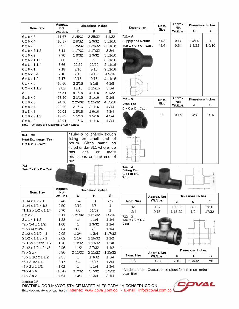
Note: Tee sizes are read Run x Run x Outlet
611 – HE Heat Exchanger Tee C x C x C – Wrot
*Tube slips entirely trough fitting on small end of return. Sizes same as listed under 611 where tee has one or more reductions on one end of run.
711 Tee C x C x C – Cast
Dimesions Inches
Nom. Size Approx.
Net Wt./Lbs. C F G
1 1/4 x 1/2 x 1 1 1/4 x 1/2 x 1/2 *1 1/2 x 1/2 x 1 1/4 2 x 2 x 3 2 x 1 x 1 1/2 *2 x 3/4 x 1 1/2 *2 x 3/4 x 3/4 2 1/2 x 2 1/2 x 3 2 1/2 x 1 1/2 x 2 *2 1/2x 1 1/2x 11/2 2 1/2 x 1/2 x 2 1/2 *3 x 3 x 4 *3 x 2 1/2 x 1 1/2 *3 x 2 1/2 x 1 *3 x 2 x 1 1/2 *4 x 4 x 6 *4 x 2 x 2
0.48 0.50 0.70 3.11 1.23 1.08 0.84 2.98 2.02 1.76 2.46 6.96 2.53 2.17 2.62 16.47 4.64
3/4 9/16 7/8
1 21/32 1 1
21/32 1 3/4 1 1/4
1 3/32 1 1/2
2 11/32 1
3/4 1
3 7/32 1 3/4
3/4 5/8
31/32 1 21/32 1 1/4 1 3/32
7/8 1 3/4
1 15/32 1 13/32 2 7/32
2 11/32 1 3/32 13/16 1 1/4 3 7/32 1 3/4
7/8 1 1
1 5/16 1 1/4 1 1/4 1 1/4
1 17/32 1 1/2 1 3/8 1 1/2
1 23/32 1 3/4 1 3/4 1 3/4
2 9/32 2 1/4
Dimesions Inches Description Nom.
Size Approx.
Net Wt./Lbs. C J
711 – A Supply and Return Tee C x C x C – Cast
*1/2 *3/4
0.17 0.34
13/16 1 3/32
1
1 5/16
Dimesions Inches Nom. Size
Approx. Net
Wt./Lbs. A C 711 – 5 Drop Tee C x C x C – Cast
1/2
0.16
3/8
7/16
611 – 2 Fitting Tee C x Ftg x C – Wrot
Dimesions Inches
Nom. Size Approx. Net
Wt./Lbs. B C F 1/2 3/4
0.07 0.15
1 1/32 1 15/32
3/8 1/2
7/16 17/32
712 – 3 Tee C x F x F – Cast
Dimesions Inches Nom. Size
Approx. Net
Wt./Lbs. C E S *1/2 0.23 7/16 1 3/32 7/8
*Made to order. Consult price sheet for minimum order quantities.
Página 20 DISTRIBUIDOR MAYORISTA DE MATERIALES PARA LA CONSTRUCCIÓN Este documento lo encuentra en Internet: www.coval.com.co - E-mail: [email protected]
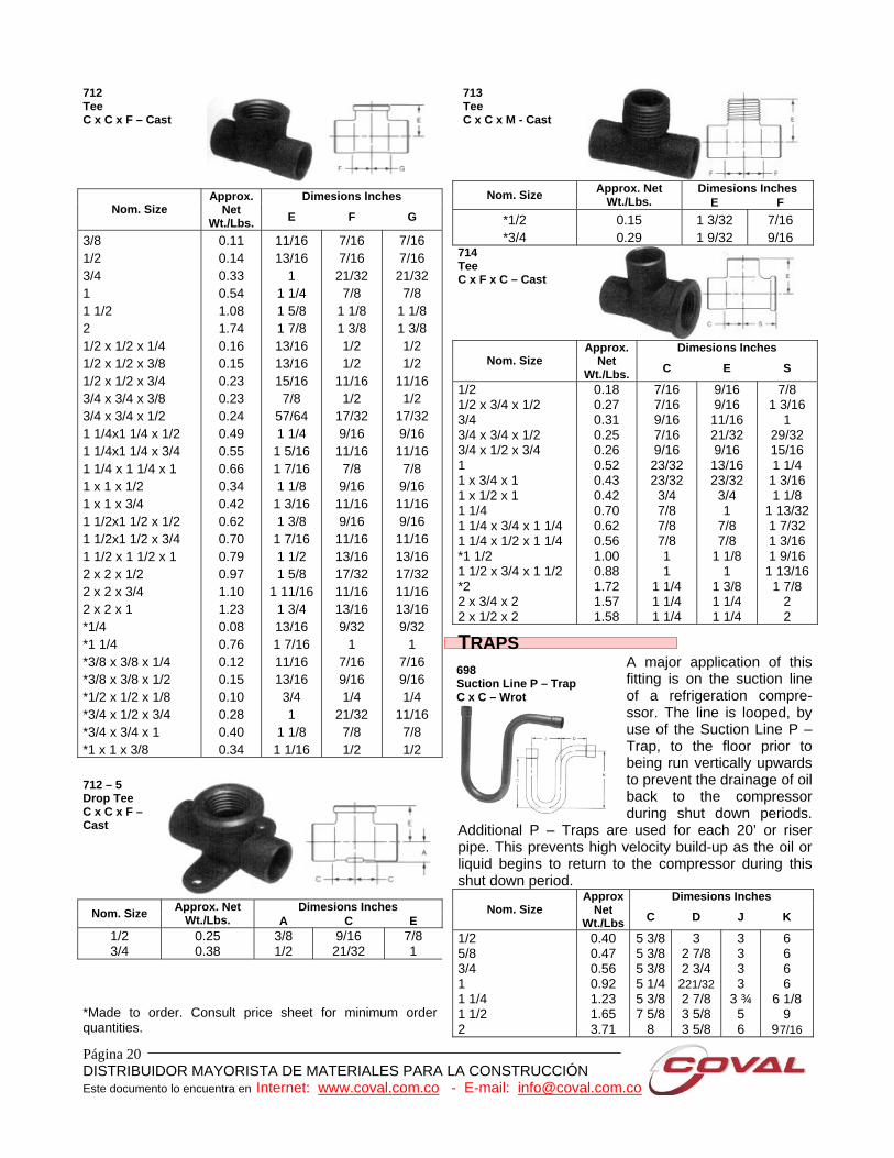
712 Tee C x C x F – Cast
Dimesions Inches
Nom. Size Approx.
Net Wt./Lbs. E F G
3/8 1/2 3/4 1 1 1/2 2 1/2 x 1/2 x 1/4 1/2 x 1/2 x 3/8 1/2 x 1/2 x 3/4 3/4 x 3/4 x 3/8 3/4 x 3/4 x 1/2 1 1/4x1 1/4 x 1/2 1 1/4x1 1/4 x 3/4 1 1/4 x 1 1/4 x 1 1 x 1 x 1/2 1 x 1 x 3/4 1 1/2x1 1/2 x 1/2 1 1/2x1 1/2 x 3/4 1 1/2 x 1 1/2 x 1 2 x 2 x 1/2 2 x 2 x 3/4 2 x 2 x 1 *1/4 *1 1/4 *3/8 x 3/8 x 1/4 *3/8 x 3/8 x 1/2 *1/2 x 1/2 x 1/8 *3/4 x 1/2 x 3/4 *3/4 x 3/4 x 1 *1 x 1 x 3/8
0.11 0.14 0.33 0.54 1.08 1.74 0.16 0.15 0.23 0.23 0.24 0.49 0.55 0.66 0.34 0.42 0.62 0.70 0.79 0.97 1.10 1.23 0.08 0.76 0.12 0.15 0.10 0.28 0.40 0.34
11/16 13/16
1 1 1/4 1 5/8 1 7/8 13/16 13/16 15/16 7/8
57/64 1 1/4
1 5/16 1 7/16 1 1/8
1 3/16 1 3/8
1 7/16 1 1/2 1 5/8
1 11/16 1 3/4 13/16 1 7/16 11/16 13/16 3/4 1
1 1/8 1 1/16
7/16 7/16
21/32 7/8
1 1/8 1 3/8 1/2 1/2
11/16 1/2
17/32 9/16
11/16 7/8 9/16
11/16 9/16
11/16 13/16 17/32 11/16 13/16 9/32
1 7/16 9/16 1/4
21/32 7/8 1/2
7/16 7/16 21/32 7/8
1 1/8 1 3/8 1/2 1/2
11/16 1/2
17/32 9/16 11/16 7/8
9/16 11/16 9/16 11/16 13/16 17/32 11/16 13/16 9/32
1 7/16 9/16 1/4
11/16 7/8 1/2
712 – 5 Drop Tee C x C x F – Cast
Dimesions Inches Nom. Size Approx. Net Wt./Lbs. A C E
1/2 3/4
0.25 0.38
3/8 1/2
9/16 21/32
7/8 1
*Made to order. Consult price sheet for minimum order quantities.
713 Tee C x C x M - Cast
Dimesions Inches Nom. Size Approx. Net
Wt./Lbs. E F *1/2 *3/4
0.15 0.29
1 3/32 1 9/32
7/16 9/16
714 Tee C x F x C – Cast
Dimesions Inches
Nom. Size Approx.
Net Wt./Lbs. C E S
1/2 1/2 x 3/4 x 1/2 3/4 3/4 x 3/4 x 1/2 3/4 x 1/2 x 3/4 1 1 x 3/4 x 1 1 x 1/2 x 1 1 1/4 1 1/4 x 3/4 x 1 1/4 1 1/4 x 1/2 x 1 1/4 *1 1/2 1 1/2 x 3/4 x 1 1/2 *2 2 x 3/4 x 2 2 x 1/2 x 2
0.18 0.27 0.31 0.25 0.26 0.52 0.43 0.42 0.70 0.62 0.56 1.00 0.88 1.72 1.57 1.58
7/16 7/16 9/16 7/16 9/16 23/32 23/32 3/4 7/8 7/8 7/8 1 1
1 1/4 1 1/4 1 1/4
9/16 9/16 11/16 21/32 9/16 13/16 23/32 3/4 1
7/8 7/8
1 1/8 1
1 3/8 1 1/4 1 1/4
7/8 1 3/16
1 29/32 15/16 1 1/4
1 3/16 1 1/8
1 13/32 1 7/32 1 3/16 1 9/16 1 13/16 1 7/8
2 2
TRAPS A major application of this fitting is on the suction line of a refrigeration compre-ssor. The line is looped, by use of the Suction Line P – Trap, to the floor prior to being run vertically upwards to prevent the drainage of oil back to the compressor during shut down periods.
Additional P – Traps are used for each 20’ or riser pipe. This prevents high velocity build-up as the oil or liquid begins to return to the compressor during this shut down period.
Dimesions Inches Nom. Size
Approx Net
Wt./Lbs C D J K
1/2 5/8 3/4 1 1 1/4 1 1/2 2
0.40 0.47 0.56 0.92 1.23 1.65 3.71
5 3/8 5 3/8 5 3/8 5 1/4 5 3/8 7 5/8
8
3 2 7/8 2 3/4
221/32 2 7/8 3 5/8 3 5/8
3 3 3 3
3 ¾ 5 6
6 6 6 6
6 1/8 9
9 7/16
698 Suction Line P – Trap C x C – Wrot
Página 21 DISTRIBUIDOR MAYORISTA DE MATERIALES PARA LA CONSTRUCCIÓN Este documento lo encuentra en Internet: www.coval.com.co - E-mail: [email protected]
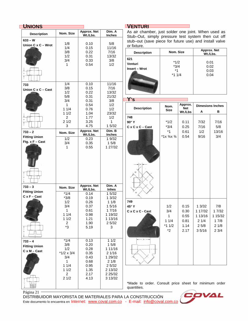
UNIONS Description Nom. Size Approx. Net
Wt./Lbs. Dim. A Inches
633 – W Union C x C – Wrot
1/8 1/4 3/8 1/2 3/4 1
0.10 0.15 0.22 0.31 0.33 0.54
5/8
11/16 7/16 13/32 3/8 1/2
733 Union C x C – Cast
1/4 3/8 1/2 5/8 3/4 1
1 1/4 1 1/2
2 2 1/2
3
0.10 0.15 0.22 0.31 0.31 0.54 0.76 1.04 1.77 3.25 4.75
11/16 7/16 13/32 21/32 3/8 1/2 1/2
23/32 1/2 1
1 5/32
Nom. Size Approx. Net Wt./Lbs.
Dim. B Inches
733 – 2 Fitting Union Ftg. x F – Cast
1/2 3/4 1
0.23 0.35 0.55
1 9/32 1 5/8
1 27/32
Nom. Size Approx. Net Wt./Lbs.
Dim. A Inhes
733 – 3 Fitting Union C x F – Cast
*1/4 *3/8 1/2 3/4 1
1 1/4 1 1/2
2 *3
0.14 0.19 0.26 0.37 0.61 0.98 1.21 1.90 5.19
1 5/32 1 3/32 1 1/8 1 5/16 1 7/16
1 19/32 1 13/16 2 5/32
3
733 – 4 Fitting Union C x M – Cast
*1/4 3/8 1/2
*1/2 x 3/4 3/4 1
1 1/4 1 1/2
2 2 1/2
0.13 0.20 0.28 0.35 0.43 0.68 0.95 1.35 2.17 4.13
1 1/2 1 5/8
1 11/16 2 1/16
1 29/32 2 1/8 2 5/32
2 13/32 2 25/32 3 13/32
VENTURI As air chamber, just solder one joint. When used as Stub–Out, simply pressure test system then cut off stub–out (save piece for future use) and install valve or fixture.
Description Nom. Size Approx. Net Wt./Lbs.
621 Venturi Insert – Wrot
*1/2 *3/4 *1
*1 1/4
0.01 0.02 0.03 0.04
Y’s Dimesions Inches
Description Nom. Size
Approx. Net
Wt./Lbs A B 748 90° Y C x C x C – Cast
*1/2 *3/4 *1
*1x ¾x ¾
0.11 0.25 0.61 0.54
7/32 7/16 1/2 9/16
7/16 5/8
13/16 3/4
749 45° Y C x C x C - Cast
1/2 3/4 1
1 1/4 *1 1/2
*2
0.15 0.30 0.55 0.81 1.14 2.17
1 3/32 1 17/32 1 13/16 2 1/4 2 5/8
3 5/16
7/8
1 7/32 1 15/32 1 7/8 2 1/8 2 3/4
*Made to order. Consult price sheet for minimum order quantities.
Página 22 DISTRIBUIDOR MAYORISTA DE MATERIALES PARA LA CONSTRUCCIÓN Este documento lo encuentra en Internet: www.coval.com.co - E-mail: [email protected]
ENGINEERING DATA
COPPER TUBE FITTINGS
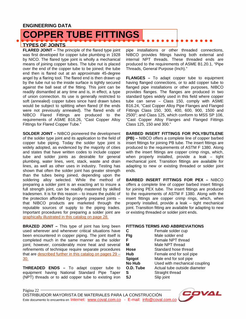
TYPES OF JOINTS FLARED JOINT – The principle of the flared type joint was first developed for copper tube plumbing in 1928 by NICO. The flared type joint is wholly a mechanical means of joining copper tubes. The tube nut is placed over the end of the copper tube to be joined; the tube end then is flared out at an approximate 45-degree angel by a flaring tool. The flared end is then drawn up by the tube nut so the inside surface is tightly secured against the ball seat of the fitting. This joint can be readily dismantled at any time and is, in effect, a type of union connection. Its use is generally restricted to soft (annealed) copper tubes since hard drawn tubes would be subject to splitting when flared (if the ends were not previously annealed). The flared ends of NIBCO Flared Fittings are produced to the requirements of ASME B16.26, “Cast Copper Alloy Fittings for Flared Copper Tube.” SOLDER JOINT – NIBCO pioneered the development of the solder type joint and its application to the field of copper tube piping. Today the solder type joint is widely adopted, as evidenced by the majority of cities and states that have written codes to include copper tube and solder joints as desirable for general plumbing, water lines, vent, stack, waste and drain lines, as well as other uses in industry. Testing has shown that often the solder joint has greater strength than the tubes being joined, depending upon the soldering alloy selected. While the method of preparing a solder joint is an exacting art to insure a full strength joint, can be readily mastered by skilled tradesmen. It is for this reason – to insure the public of the protection afforded by properly prepared joints – that NIBCO products are marketed through the reputable sources of supply to the piping trades. Important procedures for preparing a solder joint are graphically illustrated in this catalog on page 28. BRAZED JOINT – This type of joint has long been used wherever and whenever critical situations have been encountered in copper piping. The joint itself is completed much in the same manner as the solder joint; however, considerably more heat and several refinements of technique require separate procedures that are described further in this catalog on pages 29 – 30. THREADED ENDS – To adapt copper tube to equipment having National Standard Pipe Taper (NPT) threads or to add copper tube to existing iron
pipe installations or other threaded connections, NIBCO provides fittings having both external and internal NPT threads. These threaded ends are produced to the requirements of ASME B1.20.1, “Pipe Threads, General Purpose (Inch).” FLANGES – To adapt copper tube to equipment having flanged connections, or to add copper tube to flanged pipe installations or other purposes, NIBCO provides flanges. The flanges are produced in two standard types widely used in this field where copper tube can serve – Class 150, comply with ASME B16.24, “Cast Copper Alloy Pipe Flanges and Flanged Fittings Class 150, 300, 400, 600, 900, 1500 and 2500”; and Class 125, which conform to MSS SP 106, “Cast Copper Alloy Flanges and Flanged Fittings Class 125, 150 and 300.” BARBED INSERT FITTINGS FOR POLYBUTILENE (PB) – NIBCO offers a complete line of copper barbed insert fittings for joining PB tube. The insert fittings are produced to the requirements of ASTM F 1380. Along with the insert fittings are copper crimp rings, which, when properly installed, provide a leak – tight mechanical joint. Transition fittings are available for adapting to new or existing threaded or solder joint ends. BARBED INSERT FITTINGS FOR PEX – NIBCO offers a complete line of copper barbed insert fittings for joining PEX tube. The insert fittings are produced to the requirements of ASTM F 1380. Along with the insert fittings are copper crimp rings, which, when properly installed, provide a leak – tight mechanical joint. Transition fitting are available for adapting to new or existing threaded or solder joint ends. FITTINGS TERMS AND ABBREVIATIONS C Female solder cup Ftg Male solder end F Female NPT thread M Male NPT thread Hose Standard hose thread Hub Female end for soil pipe Spigot Male end for soil pipe No Hub Used with mechanical coupling O.D. Tube Actual tube outside diameter S Straight thread SJ Slip joint
Página 23 DISTRIBUIDOR MAYORISTA DE MATERIALES PARA LA CONSTRUCCIÓN Este documento lo encuentra en Internet: www.coval.com.co - E-mail: [email protected]
WHAT MAKES A PLUMBING SYSTEM FAIL? Failure in a copper plumbing system is rare, but may occur due to a variety of reasons. The most common causes of failure are: 1. Excessive fluid velocity causes erosion –
corrosion or impingement (to strike or hit against) attack in the tube and/or fitting. For this reason, the copper plumbing industry has establish design velocity limits for copper plumbing systems to the following: Hot Water>140° F (60° C) 2 to 3 feet per second
(0.6 to 0.9 meters per second)
Hot Water< 140° F (60° C) 4 to 5 feet per second (1.2 to 1.5 meters per second)
Cold Water 5 to 8 feet per second (1.5 to 2.4 meters per second)
2. Workmanship
System life by creating localized high velocities and/or turbulence. The presence of a dent, tube ends, which are not reamed or deburred before soldering, and sudden changes in direction can all cause, localized high velocity conditions.
3. Flux Corrosion
Is typified by pinhole leaks, generally in the bottom of a horizontal line. Fluxes are mildly corrosive liquid or petroleum – based pastes containing chlorides of zinc and ammonia. Unless the flux is flushed from the system, it will lay in the bottom of the tube and remain active. ASTM B813, “Liquid and Paste Fluxes for Soldering Applications of Copper and Copper – Alloy Tube,” limits the corrosivity of soldering fluxes and ensures that these fluxes are flushable in cold water, which facilitates easy removal of flux residue following installation.
4. Galvanic Corrosion May be defined as the destruction of a material by electrochemical interaction between the environment and the material. Generally, it is slow but persistent in character and requires the presence of dissimilar metals. Galvanic corrosion requires the flow of and electric current between certain areas of dissimilar metal surfaces. To complete the electric circuit, there must be two electrodes, an anode and a cathode, and they must be connected by an electrolyte media (water) through which the current can pass. The amount of metal which dissolves at the anode is proportional to the number of electrons flowing, which in turn is dependent upon the potential and resistance of the two metals. The use of dissimilar metals in a plumbing system may or my not create a problem. For instance, copper and steel are perhaps the most common dissimilar metals found together in a plumbing system. In closed systems, such as chilled or heating water piping, the use of dissimilar metals may not create a serious problem; this is because there is virtually no oxygen in the water and corrosion relations tend to be stifled. Where dissimilar metals must be used, some codes require that they should be separated by dielectric union or a similar type of fitting. The effectiveness depends upon; distance between the metals on the electromotive force series (EMF) chart, ratio of cathode to anode area, degree of aeration, amount of agitation, temperature, presence of dissolved salts, and other factors.
ABBREVIATED EMF SERIES (Electromotive – Force Series; Common Piping Materials in Sea Water)

Página 24 DISTRIBUIDOR MAYORISTA DE MATERIALES PARA LA CONSTRUCCIÓN Este documento lo encuentra en Internet: www.coval.com.co - E-mail: [email protected]
CATHODE (+) Passive
GOLD – Fixtures, Faucets, Plating PLATINUM SILVER – Brazing alloys, Silver – bearing solders TITANIUM – Condenser tubes MONEL (67% Ni – 33% Cu) – Specialty piping & equipment CUPRO – NICKEL – Condensers, Marine, Nuclear COPPER – Pressure, DWV, Gases, Air, Refrigeration, etc. BRASS (85/15 – Red) – Cast fittings, Valves BRASS (70/30 – Yellow) – Gas-cocks, fittings, Connectors LEAD – Solder, pipe, Sheet, Coating, Lining TIN – Solders, Coating, Lining CAST IRON – Pressure MILD STEEL – Fire Protection ALUMINIUM – Refrigeration, Irrigation, some Solar GALVANIZED STEEL – Pressure, DWV ZINC – Coatings, linings, some Fittings MAGNESIUM. Water Heater Anodes, Cathodic protection for pipelines
ANODE (-) Active; Sacrificial Material
Galvanic corrosion may be defined as “the destruction of a material by electrochemical interaction between the environment and the material. “ Generally it is slow but persistent in character. The basic cause of corrosion is the instability of metals in their refined forms. The metals tend to revert back to their refined forms. The metals tend to revert back to their natural states through the processes of corrosion through transformation from the metallic to the ionic state.
5. Dezincification Is a type of corrosion in which brass dissolves as an alloy and the copper constituent redeposits from solution onto the surface of the brass as a metal, but in the porous form. The zinc constituent may be carried away from the brass as a soluble salt, or may be deposited in place as an insoluble compound. Dezincification is normally associated with brass valves where the zinc content exceeds 15%. Generally, areas of high stress, such as valve stems and gate valve bodies, are primary targets of attack.
6. On rare occasion problems of corrosion by aggressive water, possibly aggravated by poor design or workmanship, do exist, Aggressive, hard well waters that cause pitting can be identified by chemical analysis and treated to bring their composition within acceptable limits. Typically these hard waters are found to have high total dissolved solids (t.d.s.) including sulfates and chlorides, a pH in the range of 7.2 to 7.8, a high content of carbon dioxide (co2) gas (over 10 parts per million, ppm), and the presence of dissolved oxygen (D.O) gas. Soft acidic waters can cause the annoying problem of green staining of fixtures or “green water”. Raising the pH of such waters to a value of about 7.2 or more usually solves the problem, but a qualified water treatment specialist should be consulted.
7. Aggressive soil conditions
Can be a cause for external corrosion of copper piping systems. Non – uniform soil characteristics, such as different soil aeration, resistivity, or moisture properties, between adjacent sections of tube can create galvanic corrosion cells. Soils contaminated with high concentrations of road salts of fertilizers containing ammonia, chlorides, and nitrogen are known to combine with water to form acids. Any metal pipe laid in ash or cinders is subject to attack by the acid generated when sulfur compounds combine with water to form sulfuric acid.

Página 25 DISTRIBUIDOR MAYORISTA DE MATERIALES PARA LA CONSTRUCCIÓN Este documento lo encuentra en Internet: www.coval.com.co - E-mail: [email protected]
SOLDER JOINT SPECIFICATION 1. Soldering clearance (between the outside of the
tube and the inside diameter of the solder cup) and the Depth of the Solder Cup (into which the tube is inserted).
Chart 1 – Soldering Clearance and Solder Cup Depth
Nominal Size of Fitting
Maximum I.D. of fitting
Minimum O.D. of tube
Maximum Clearance
for Soldering
Depth of Solder Cup
(Inches) Inch -(mm) Inch -(mm) Inch (mm) Inch (mm)1/4 3/8 1/2 5/8 3/4 1
1 1/4 1 1/2
2 2 1/2
3 3 1/2
4 5 6
0.381 0.506 0.631 0.756 0.881 1.132 1.382 1.633 2.133 2.633 3.133 3.633 4.133 5.133 6.133
9.66 12.85 16.03 19.20 22.38 28.75 35.10 41.48 54.18 66.88 79.58 92.28 104.98 130.38 155.78
0.374 0.499 0.624 0.749 0.874 1.123 1.373 1.623 2.123 2.623 3.123 3.623 4.123 5.123 6.123
9.50 12.67 15.85 19.02 22.20 28.54 34.88 41.22 53.92 66.62 79.32 92.02
104.72 1130.12 155.52
0.007 0.007 0.007 0.007 0.007 0.008 0.008 0.010 0.010 0.010 0.010 0.010 0.010 0.010 0.010
0.18 0.18 0.18 0.18 0.18 0.2160.2160.25 0.25 0.25 0.25 0.25 0.25 0.25 0.25
0.310.380.500.620.750.910.971.091.341.471.661.912.162.663.09
7.9 9.7 12.7 15.7 19.1 23.1 24.6 27.7 34.0 37.3 42.2 48.5 54.9 67.6 78.5
The National Bureau of Standards Report BMS58, “Strength of Soft – Soldered Joints in Copper Tubing,” reporting on test conducted with ¾ - inch tubing and fitting, says “When the clearance is greater than 0.010 inch (0.25 mm), there is difficulty in filing the joint properly.” 2. Depth of Solder Penetration drastically affects
the breaking load of the joint. When there is too great a soldering clearance, there is no capillary flow to assure complete solder penetration. As shown in the chart below, the holding power of the ¾ - inch joint is directly proportional to the depth of solder penetration.
For example: if you get only one-third penetration, you get approximately one – third the strength needed to assure complete satisfaction.
Solder penetration of one -third the cup depth – breaking load, approximately 2,100 lb. (955 Kg)
Solder penetration of the entire cup depth – breaking load approximately 7,000 lb. (3175 Kg)
Chart 2 – Type K ¾” Tubing
DEPTH OF BORE, INCHES (mm)
HOW TO BE SURE OF PROPER TOLERANCES It is apparent that all of the scientific apparatus used to test tube and fittings, according to the dimensions indicated in Chart 1, would be impractical to use on the job. It is therefore essential that you install tube and fittings manufactured by companies know to be dedicated to the highest quality control standards. Should you encounter a condition where there is difficulty in filing the joint properly, NIBCO will analyze the trouble without charge. Just send six inches of the tube, along with the fitting and our technicians will provide you with an authoritative report. U.S. customary units in this document are the standard; the metric units are provided for reference only. The values stated in each system are not exact equivalents.

Página 26 DISTRIBUIDOR MAYORISTA DE MATERIALES PARA LA CONSTRUCCIÓN Este documento lo encuentra en Internet: www.coval.com.co - E-mail: [email protected]
BRAZING INFORMATION
Cooper Water
Tube Size Brazing* Filler
Required Torch
Tip Drill Size No.
Acetylene Consumption
For Estimating Purposes Oxygen Pressure (Approx)
Acetylene Pressure (Approx)
Inches Inches Mm C.F.H. C.M.H. PSI Kpa PSI Kpa 1/4 3/8 1/2 5/8 3/4 1
1 1/4 1 1/2
2 2 1/2
3 3 1/2
4 5 6
0.25 B
0.38 B
0.50 0.62 1.00 1.60 2.00 2.60 4.40 5.90 7.90 10.50 13.50 20.50 28.50
6.4 9.7
12.7 15.7 25.0 41.0 51.0 66.0 112.0 150.0 200.0 207.0 343.0 521.0 724.0
54 54 51 51 51 48 48 44 40 40 35 35 30 30 30
15.9 15.9 24.8 24.8 24.8 31.6 31.6 38.7 60.0 60.0 70.0 70.0 88.5 88.5 88.5
0.5 0.5 0.7 0.7 0.7 0.9 0.9 1.1 1.7 1.7 2.0 2.0 2.5 2.5 2.5
4 4 5 5 5 6 6 7 7 7
7 1/2 7 1/2
9 9 9
27 27 34 34 34 41 41 48 48 48 52 52 62 62 62
4 4 5 5 5 6 6 7 7 7
7 1/2 7 1/2
9 9 9
27 27 34 34 34 41 41 48 48 48 52 52 62 62 62
* Approximate consumption when brazing one cup of the fittings. Actual consumption depends on workmanship. For filler sizes shown, one pound of filler alloy provides 1.068 inches (27.13 mm) of 1/16 –inch wire or 475 inches (12.065 mm) of 3/32 -inch wire.
A 1/16 –inch (1.59 mm) diameter wire; all other is 3/32 –inch (2.38 mm) diameter. SOLDER AND FLUX REQUIREMENTS Nom. Size Joint Solder Required,
LBG (kg) Inches General Use Drainage Use
1/4 3/8 1/2 5/8 3/4 1
1 1/4 1 1/2
2 2 1/2
3 3 1/2
4 5 6 8
0.097 0.159 0.261 0.389 0.548 0.856 1.115 1.480 2.380 3.225 4.335 5.786 7.446
11.392 15.815 26.955
- - - - - -
1.2 0.5 1.4 0.6 1.5 0.7
- 2.8 1.3
- 4.2 1.9
- - -
Solder requirements in this table are based on estimate of weight of solder used to prepare 100 solder joints of sizes shown. Two (2) ounces (0.06 Kg) of solder flux will be required for each pound (0.45 Kg) of solder. U.S. customary units in this document are the standard; the metric units are provided for reference only. The values stated in each system are not exact equivalents.
Página 27 DISTRIBUIDOR MAYORISTA DE MATERIALES PARA LA CONSTRUCCIÓN Este documento lo encuentra en Internet: www.coval.com.co - E-mail: [email protected]
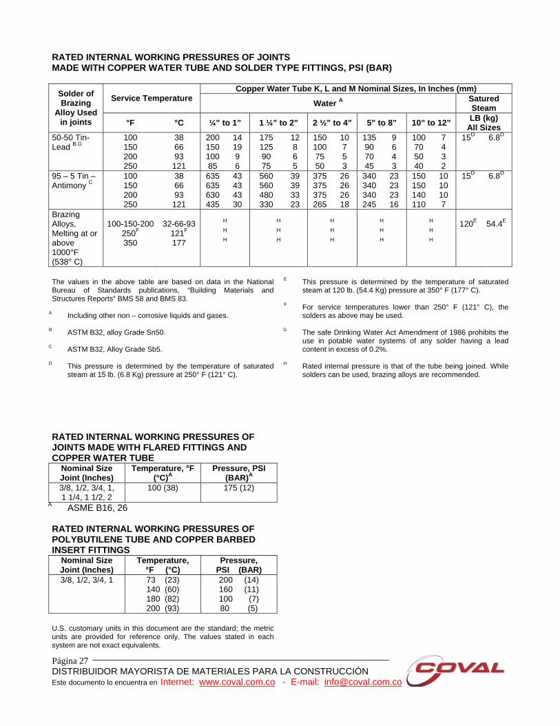
RATED INTERNAL WORKING PRESSURES OF JOINTS MADE WITH COPPER WATER TUBE AND SOLDER TYPE FITTINGS, PSI (BAR)
Copper Water Tube K, L and M Nominal Sizes, In Inches (mm) Service Temperature Water A Satured
Steam
Solder of Brazing
Alloy Used in joints °F °C ¼” to 1” 1 ¼” to 2” 2 ½” to 4” 5” to 8” 10” to 12” LB (kg)
All Sizes 50-50 Tin- Lead B.G
100 150 200 250
38 66 93 121
200 150 100 85
14 19 9 6
175 125 90 75
12 8 6 5
150 100 75 50
10 7 5 3
135 90 70 45
9 6 4 3
100 70 50 40
7 4 3 2
15D 6.8D
95 – 5 Tin – Antimony C
100 150 200 250
38 66 93 121
635 635 630 435
43 43 43 30
560 560 480 330
39 39 33 23
375 375 375 265
26 26 26 18
340 340 340 245
23 23 23 16
150 150 140 110
10 10 10 7
15D 6.8D
Brazing Alloys, Melting at or above 1000°F (538° C)
100-150-200
250F 350
32-66-93
121F 177
H
H
H
H
H
H
H
H
H
H
H
H
H
H
H
120E
54.4E
The values in the above table are based on data in the National Bureau of Standards publications, “Building Materials and Structures Reports” BMS 58 and BMS 83.
A Including other non – corrosive liquids and gases.
B ASTM B32, alloy Grade Sn50.
C ASTM B32, Alloy Grade Sb5.
D This pressure is determined by the temperature of saturated steam at 15 lb. (6.8 Kg) pressure at 250° F (121° C).
E This pressure is determined by the temperature of saturated steam at 120 lb. (54.4 Kg) pressure at 350° F (177° C).
F For service temperatures lower than 250° F (121° C), the
solders as above may be used.
G The safe Drinking Water Act Amendment of 1986 prohibits the use in potable water systems of any solder having a lead content in excess of 0.2%.
H Rated internal pressure is that of the tube being joined. While
solders can be used, brazing alloys are recommended. RATED INTERNAL WORKING PRESSURES OF JOINTS MADE WITH FLARED FITTINGS AND COPPER WATER TUBE
Nominal Size Joint (Inches)
Temperature, °F (°C)A
Pressure, PSI (BAR)A
3/8, 1/2, 3/4, 1, 1 1/4, 1 1/2, 2
100 (38) 175 (12)
A ASME B16, 26 RATED INTERNAL WORKING PRESSURES OF POLYBUTILENE TUBE AND COPPER BARBED INSERT FITTINGS
Nominal Size Joint (Inches)
Temperature, °F (°C)
Pressure, PSI (BAR)
3/8, 1/2, 3/4, 1 73 (23) 140 (60) 180 (82) 200 (93)
200 (14) 160 (11) 100 (7) 80 (5)
U.S. customary units in this document are the standard; the metric units are provided for reference only. The values stated in each system are not exact equivalents.

Página 28 DISTRIBUIDOR MAYORISTA DE MATERIALES PARA LA CONSTRUCCIÓN Este documento lo encuentra en Internet: www.coval.com.co - E-mail: [email protected]
RATED INTERNAL WORKING PRESSURE1 FOR COPPER FITTINGS, PSI (BAR)
Water Temperature Range Nominal Water
Tube Size -20° to 100°F 150°F 200°F 250°F 300°F 350°F 400°F
Inches (-29° to 38°C) 66°C 95°C 120°C 177°C 177°C 204°C 1/4 3/8 1/2 5/8 3/4 1
1 1/4 1 1/2
2 2 1/2
3 3 1/2
4 5 6 8
912 779 722 631 582 494 439 408 364 336 317 304 293 269 251 270
62 54 50 43 40 34 30 28 25 23 22 21 20 19 17 19
775 662 613 537 495 420 373 347 309 285 270 258 249 229 213 230
53 46 42 37 34 29 26 24 21 20 19 18 17 16 15 16
729 623 577 505 466 395 351 327 291 269 254 243 235 215 201 216
50 43 40 35 32 27 24 23 20 19 17 17 16 15 14 15
729 623 577 505 466 395 351 327 291 269 254 243 235 215 201 216
50 43 40 35 32 27 24 23 20 19 17 17 16 15 14 15
714 610 565 495 456 387 344 320 285 263 248 238 230 211 196 212
49 42 39 34 31 26 23 22 20 18 17 16 16 15 14 15
608 519 481 421 388 330 293 272 242 224 211 202 196 179 167 180
42 36 33 29 27 23 20 19 17 15 15 14 13 12 12 12
456 389 361 316 291 247 219 204 182 168 159 152 147 135 125 135
31 27 25 21 20 17 15 14 13 12 11 10 10 9 8 9
The fitting pressure rating applies to the largest opening of the fitting.
RATED INTERNAL WORKING PRESSURES OF CAST COPPER ALLOY FLANGES AND FLANGED FITTINGS
Nominal Size Joint Temperature Pressure (PSI)
Inches °F (°C) A Class 125 A, B
Class 150 B
Class 150A, C
1/2, 3/4, 1, 1 1/4,
1 1/2, 2, 2 1/2, 3, 4,
5, 6, 8 (also 10” for Class
125)
0– 150 175 200 225 250 275 300 350 406
0 – 66 79 93
107 121 135 149 177 208
105 100 95 90 90 85 85 75 70
7 7 7 6 6 6 6 5 5
210 205 195 190 180 175 170 150 140
14 14 13 13 12 12 12 10 9
225 220 210 205 195 190 180 165 150
15 15 15 14 13 13 12 11 10
A MSS SP – 106 B ASTM B584, UNS C83800 and UNS C84400 C ASTM B62, UNS C83600 and ASTM B584, UNS C83600 U.S. customary units in this document are the standard; the metric units are provided for reference only. The values stated in each system are not exact equivalents.

Página 29 DISTRIBUIDOR MAYORISTA DE MATERIALES PARA LA CONSTRUCCIÓN Este documento lo encuentra en Internet: www.coval.com.co - E-mail: [email protected]
THE FINE ART OF SOLDERING
Installation Instructions
When adjoining of copper and copper alloys meet under proper conditions of cleanliness and temperature, solder will make a perfect adhesion. The strength of joint is equal to or even greater than the strength of tube alone. Surface tension seals the joint. Capillary attraction draws solder into, around, and all about the joint. It’s easy to learn to make a perfect solder joint when you use NIBCO Fittings. WITH 95-5 SOLDER AND INTERMEDIATELY CORROSIVE FLUX 1. Cut tube end square, ream, burr and size.
2. Use sand cloth or steel wire brush to clean tube and cup to a bright metal finish.
3. Apply solder flux to outside of tube and inside of cup of fitting carefully so that surfaces to be joined are completely covered. Use flux sparingly.
4. Apply flame to the fitting to heat tube and solder cup of fitting until solder melts when placed at joint of tube and fitting.
5. Remove flame and feed solder into the joint at one or two points until a ring of solder appears at the end of the fitting. The correct amount of solder is approximately equal to 1 ½ the diameter of the fitting… ¾” (20 mm) solder for ½” fitting, etc.
6. Remove excess solder with a small brush or wiping cloth while the solder is plastic.
Página 30 DISTRIBUIDOR MAYORISTA DE MATERIALES PARA LA CONSTRUCCIÓN Este documento lo encuentra en Internet: www.coval.com.co - E-mail: [email protected]
THE FINE ART OF BRAZING Best results will be obtained by a skilled operator employing the step – by – step brazing technique that follows: 1. The tube should be cut to desired length with a
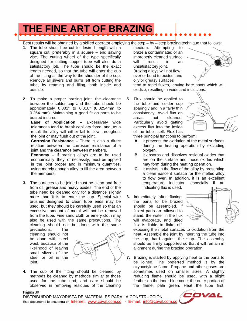
square cut, preferably in a square – end sawing vise. The cutting wheel of the type specifically designed for cutting copper tube will also do a satisfactory job. The tube should be the exact length needed, so that the tube will enter the cup of the fitting all the way to the shoulder of the cup. Remove all slivers and burrs left from cutting the tube, by reaming and filing, both inside and outside.
2. To make a proper brazing joint, the clearance
between the solder cup and the tube should be approximately 0.001” to 0.010” (0.0254mm to 0.254 mm). Maintaining a good fit on parts to be brazed insures: Ease of Application – Excessively wide tolerances tend to break capillary force; and, as a result the alloy will either fail to flow throughout the joint or may flush out of the joint. Corrosion Resistance – There is also a direct relation between the corrosion resistance of a joint and the clearance between members. Economy – If brazing alloys are to be used economically, they, of necessity, must be applied in the joint proper and in minimum quantities, using merely enough alloy to fill the area between the members.
3. The surfaces to be joined must be clean and free
from oil, grease and heavy oxides. The end of the tube need be cleaned only for a distance slightly more than it is to enter the cup. Special wire brushes designed to clean tube ends may be used, but they should be carefully used so that an excessive amount of metal will not be removed from the tube. Fine sand cloth or emery cloth may also be used with the same precautions. The cleaning should not be done with the same precautions. The cleaning should not be done with steel wool, because of the likelihood of leaving small slivers of the steel or oil in the joint.
4. The cup of the fitting should be cleaned by
methods be cleaned by methods similar to those used for the tube end, and care should be observed in removing residues of the cleaning
medium. Attempting to braze a contaminated or an improperly cleaned surface will result in an unsatisfactory joint. Brazing alloys will not flow over or bond to oxides; and oily or greasy surfaces tend to repel fluxes, leaving bare spots which will oxidize, resulting in voids and inclusions.
5. Flux should be applied to
the tube and solder cup sparingly and in a fairly thin consistency. Avoid flux on areas not cleaned. Particularly avoid getting excess flux into the inside of the tube itself. Flux has three principal functions to perform: A. It prevents the oxidation of the metal surfaces
during the heating operation by excluding oxygen.
B. It absorbs and dissolves residual oxides that are on the surface and those oxides which may form during the heating operation.
C. It assists in the flow of the alloy by presenting a clean nascent surface for the melted alloy to flow over. In addition, it is an excellent temperature indicator, especially if an indicating flux is used.
6. Immediately after fluxing,
the parts to be brazed should be assembled. If fluxed parts are allowed to stand, the water in the flux will evaporate, and dried flux is liable to flake off, exposing the metal surfaces to oxidation from the heat. Assemble the joint by inserting the tube into the cup, hard against the stop. The assembly should be firmly supported so that it will remain in alignment during the brazing operation.
7. Brazing is started by applying heat to the parts to
be joined. The preferred method is by the oxyacetylene flame. Propane and other gases are sometimes used on smaller sizes. A slightly reducing flame should be used, with a slight feather on the inner blue cone; the outer portion of the flame, pale green. Heat the tube first,
Página 31 DISTRIBUIDOR MAYORISTA DE MATERIALES PARA LA CONSTRUCCIÓN Este documento lo encuentra en Internet: www.coval.com.co - E-mail: [email protected]
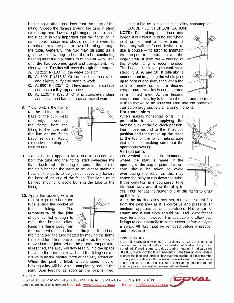
beginning at about one inch from the edge of the fitting. Sweep the flames around the tube in short strokes up and down at right angles to the run of the tube. It is very important that the flame be in continuous motion and should not be allowed to remain on any one point to avoid burning through the tube. Generally, the flux may be used as a guide as to how long to heat the tube, continuing heating after the flux starts to bubble or work, and until the flux becomes quiet and transparent, like clear water. The flux will pass through four stages: A. At 212° F (100° C) the water boils off. B. At 600° F (315.6° C) the flux becomes white
and slightly puffy and starts to work. C. At 800° F (426.7! C) It lays against the surface
and has a milky appearance. D. At 1100° F (593.3° C) it is completely clear
and active and has the appearance of water. 8. Now switch the flame
to the fitting at the base of the cup. Heat uniformly, sweeping the flame from the fitting to the tube until the flux on the fitting becomes quiet. Avoid excessive heating of cast fittings.
9. When the flux appears liquid and transparent on
both the tube and the fitting, start sweeping the flame back and forth along the axis of the joint to maintain heat on the parts to be joint to maintain heat on the parts to be joined, especially toward the base of the cup of the fitting. The flame must be kept moving to avoid burning the tube or the fitting.
10. Apply the brazing wire or
rod at a point where the tube enters the socket of the fitting. The temperature of the joint should be hot enough to melt the brazing alloy. Keep the flame away from the rod or wire as it is fed into the joint. Keep both the fitting and the tube heated by moving the flame back and forth from one to the other as the alloy is drawn into the joint. When the proper temperature is reached, the alloy will flow readily into the space between the tube outer wall and the fitting socket, drawn in by the natural force of capillary attraction. When the joint is filled, a continuous fillet of brazing alloy will be visible completely around the joint. Stop feeding as soon as the joint is filled,
using table as a guide for the alloy consumption. (SOLDER JOINT SPECIFICATION)
NOTE: For tubing one inch and larger, it is difficult to bring the whole joint up to heat at one time. It frequently will be found desirable to use a double – tip torch to maintain the proper temperature over the larger area. A mild pre – heating of the whole fitting is recommended. The heating then can proceed as in steps 7, 8, 9, and 10. If difficulty is encountered in getting the whole joint up to heat at one time, then when the joint is nearly up to the desired temperature the alloy is concentrated in a limited area. At the brazing temperature the alloy is fed into the joint and the torch is then moved to an adjacent area and the operation carried on progressively all around the joint. Horizontal joints When making horizontal joints, it is preferable to start applying the brazing alloy at the 5o’ clock position, then move around to the 7 o’clock position and then move up the sides to the top of the joint, making sure that the joint, making sure that the operations overlap. Vertical joints On vertical joints, it is immaterial where the start is made. If the opening of the cup is pointed down, care should be taken to avoid overheating the tube, as this may cause the alloy to run down the tube. If this condition is encountered, take the heat away and allow the alloy to set. Then reheat the solder cup of the fitting to draw up the alloy. After the brazing alloy has set, remove residual flux from the joint area as it is corrosive and presents an unclean appearance and condition. Hot water or steam and a soft cloth should be used. Wrot fittings may be chilled; however it is advisable to allow cast fittings to cool naturally to some extent before applying a swab. All flux must be removed before inspection and pressure testing. TROBLE SPOTS If the alloy fails to flow or has a tendency to ball up, it indicates oxidation on the metal surfaces, or insufficient heat on the parts to be joined. If work starts to oxidize during heating, it indicates too little flux, or a flux of too thin consistency. If the brazing alloy refuses to enter the joint and tends to flow over the outside of either member of the joint, it indicates this member is overheated, or the other is under heated, or both. In both cases, operations should be stopped and the joints disassembled, recleaned and fluxed.
Página 32 DISTRIBUIDOR MAYORISTA DE MATERIALES PARA LA CONSTRUCCIÓN Este documento lo encuentra en Internet: www.coval.com.co - E-mail: [email protected]
FREQUENTLY ASKED QUESTIONS Q: What is the pressure rating of a given fitting? A: Fittings are rated per Table 1 of ASME B16.22. The system rated pressure shall be the lowest of the fitting, tube or joint. Q: When copper fails in a system, what is the problem? A: MOST COMMON: 1. Velocity – fluid is moving too fast.
Recommendation: 2-3 fps (0.0508 – 0.0762 m/s) hot water < 140°F, 5-8 fps (0.127 – 0.2032 m/s) cold water.
2. Turbulence – burrs left on the cut tubing causes a
tumbling effect causing localized erosion and eventual failure.
3. Aggressive Waters – tend to cause pitting or
green staining of fixtures. Aggressive, hard well waters that cause pitting typically are found to have total dissolved solids including suflates en chlorides, a pH in the range of 7.2 to 7.8, a high content of carbon dioxide gas and the presence of dissolved oxygen gas. Soft acidic waters that cause green staining typically tend to be more corrosive. Low alkalinity, low mineralization, pH levels of 7 or lower should be avoided.
LESS COMMON 1. Flux corrosion – using too much flux when
making joints can potentially leave residue and cause isolated corrosion. Flux should be used sparingly and system adequately flushed.
2. Electrolysis – stray (D.C:) current; inadequate
grounding for the piping. 3. Sand or other solid particulates –
erosion/corrosion problems can occur. Lower velocities must be maintained if solids are present in flow media.
4. Galvanic corrosion – destruction of a material by
electrochemical interaction between the environment and the material.
Q: Copper tubing wall thickness is designated “K,” “L” or “M:” What are the copper fittings applicable to?
A: Copper fittings’ wall thickness is determined by standards (ASME B – 16:22 and MSS – SP – 104). These standards address minimum wall thickness (per size) for the full range of copper fittings and are not intended to mach tubing wall thicknesses. Q: Can dissimilar metals (i.e., copper and iron) be joined together without use of dielectric insulators to prevent corrosion? A: In most situations dissimilar metals (copper/iron/steel) can be joined successfully without using dielectric insulators. Factors to consider: 1. The composition of the two metals. 2. The rate of liquid flow past the two metals. 3. Chemicals in the water which could enhance or
destroy protective films. 4. The relative areas of the two metals – unless the
surface area of the less noble (steel) material is less that 5% of the more noble (copper) material, the need for dielectric separator is not needed. (Failures due to galvanic corrosion are very unusual and only occur under very strict conditions.)
5. Local code requirements. Q: What should the installer of copper unions know and do in order to assure a proper leak – free installation? A: The following should be done: 1. Make sure the ground – joint (mating area of
unions tail and thread pieces) are free of nicks and scratches.
2. Spray the ground – joint area with a food grade
silicone spray or apply bees wax to enhance seating.
3. Make sure alignment of line does not put lateral
stress on the ground – joint seal. 4. Make sure that excess solder (droplets) do not
reach the ground – joint area.

Página 33 DISTRIBUIDOR MAYORISTA DE MATERIALES PARA LA CONSTRUCCIÓN Este documento lo encuentra en Internet: www.coval.com.co - E-mail: [email protected]
RESIDENTIAL COPPER PLUMBING PRODUCTS LIMITED WARRANTY What the warranty terms mean In this warranty “Manufacturer” refers to the company listed below which manufactured the product and any person or company that assumes its obligations under this warranty. “Homeowner” means you as the owner of the residential building in the United States in which the product has been installed and also means any succeeding owner during the original warranty term. “Product” means the copper water tube and/or copper or brass fittings manufactured by the manufacturer for the residential building market in the United States. Each Manufacturer listed below separately and individually warrants only products it has manufactured and does not warrant Products of any other company, whether or not listed below. Date the warranty begins The warranty begins on the date of the new home purchase, or in the case of home additions or renovations, on the date the installation is completed. The warranty is transferable to succeeding Homeowners for the remainder of the original warranty term, in which case the date the warranty begins shall continue without change. What is covered The Manufacturer warrants to the Homeowner for a period of 50 Years from the date the warranty begins that its properly installed Product will be free of failure as a result of defects in material or workmanship in manufacturing the Product. What the manufacturer will do for you As long as (1) such a failure occurs within 50 years from the date the warranty begins and (2) the Homeowner promptly notifies the Manufacturer will correct that failure by repairing or replacing the product within a reasonable time, without charge. This warranty is limited to the cost of repairing or replacing the Product, including installation.
What is not covered: Disclaimer of liability for consequential and other damages The manufacturer does NOT warrant against failure: 1. Of any product, parts, or
systems that is has not manufactured;
2. If the product is used for purposes other than residential plumbing applications;
3. Caused by, contributed in whole or in part by, or resulting from, any of the following:
A. Improper installation; B. Abuse, such as, without limitation, vandalism; C. Natural disasters, such as, without limitation,
flooding, windstorm and lightning; D. Attachments or modifications to the product that
the manufacturer did not authorize; E. External causes, where external, physical or
chemical qualities produce damage to the product, such as, without limitation, aggressive water or an unsuitable or hostile environment; or
F. Any other cause beyond the Manufacturer’s control.
The Manufacturer shall NOT be liable under any circumstances for any other direct or any indirect, incidental or consequential damages of any kind. This is the only warranty This warranty is the only warranty for the Product provided by the manufacturer, and is and shall be in lieu of any and all other warranties, express or implied, including but not limited to an implied warranty of merchantability, and of all other obligations or liabilities on the part of the manufacturer. None of the Manufacturer’s employees, and no other person or business, is authorized to make any other warranty on the Manufacturer’s behalf covering the product. This warranty gives you specific legal rights, and you may also have other rights which vary from state to state. Some states do not allow the exclusion or limitation of incidental or consequential damages, so the above limitation or exclusion may not apply to you.


![NIBCO-IUSA [J V]](https://img.dokumen.tips/doc/110x75/552ab19a4a7959867b8b467d/nibco-iusa-j-v.jpg)