Embed Size (px)
Citation preview

MAl l BRAY
3.6m telescope MAINTENANCE MANUAL NUMBER 2
@
MAIN GEARS
Edition jan. 1977 J. Roozeveld van der Yen

3.6m telescope MAINTENANCE MANUAL NUMBER 2
@
MAIN' GEARS
Edition jan. 1977 J. Roozeveld van der Ven
CONTENT
page
1. Principle 1
2. Description of parts 2
3. Maintenance 9
4. Manual driving of the gearboxes. 10
5. Demounting procedure of the declination gearbox 11
6. Demounting procedure of polar axis gearbox 13
7. Mounting procedure of the declination and
polar axis gearbox
8. Replacement of the nitril rubber seal between
gearbox and gearwheel cover at the
declination axis
9 • Replacement of the nitril rubber seal between
gearbox and gearwheel cover at the
polar axis
10. Demounting of the motor assembly
15
17
19
20

- 1 -
1. PRINCIPLE
The complete main gears are shown on drawings T 10-100
and T 11-100. Both telescope axes are driven by Inland
torque motors and a 3 step reduction gearbox. Most of
the parts and subparts of these ge~rs are identical at
both telescope axes. The gear backlash is eliminated by
the braking action of one of the drive motors. The motors
are built together to one unit with a tachometer and an
electromagnetical friction brake. This brake automatically
engages by spring force when the motor current is cut off.
To the gear boxes are mounted an incremental encoder,
a Heidenhain backup position encoder and a Siemens absolute
encoder. Each main gear consists of two main parts, the
big gearwheel with cover, and the gear box. To obtain the
correct position between the main parts, a system of guiding
rollers has been applied. Between the parts is a flexible
rubber seal to prevent oil leakage.
A moment arm, provided with 2 ball heads connects the
gearbox to the telescope structure. Gearwheels and bearings
are oil lubricated. At the polar axis the lubrication unit
is part of the gearbox. At the declination axis, this unit
is located inside the V-beam to obtain a correct oil return
in all telescope positions. The load on the guiding rollers
is reduced by a compensation mechanism. At the polar axis·
it is a simple spring system and at the declination axis
a counterweight-lever system with vibration damper.
The gears are protected for too low oil pressure by the
manometer, that is provided by electrical contacts giving
a signal that cuts off the motor current.
- 2 -
2. DESCRIPTION OF PARTS
2.1 11otor assembly T 10-101
Identical for both telescope axes, the motor assembly
consists of Inland motor model T12008,'Inland tachometer
model TG-5723 and a Pintch Bamag electromagnetic
II Zweiflachen-Federdruck II brake" type EFB 5 Ost, that
automatically comes in when the current is cut off.
These parts are fitted on a heavy shaft that is
supported on a pre loaded set of conical bearings and a
needle bearing with reduced clearance. The brake is
fitted on an extended shaft that is screwed to the main
shaft. Its end is provided with a hexagon for manual
drive. The shaft is oil tight sealed to the gearbox.
Between motor and gearbox is a cell rubber dust seal.
The first drive pignon is part of the motor shaft
between motor and tachometer, a mumetal shielding
plate is fitted. Motor and tacho are located inside
an aluminium casting.
2.2 Geartrain T 10-102
It is identical for both telescope axes, besides
the bore of the big gearwheel.
The big gearwheel is welded from mild steel sheets
and is stress relieved. The rim of alloy steel
34 Cr Ni M 06 is welded to the inner part by a special
process. The complete gearwheel forms a rigid part
which is reenforced by radial ribs. The rim at its sides
is provided with flanges, that serve as track for the
guide rollers and incremental encoder roller. Gearteeth
and side flanges are ground to a very high precision.
- 3 -
Fixation of the gearwheel to the telescope structure is
done by screws. The other gearwheels are hardened and
ground to a high degree of precision. Pignons and gearwheels
are respectively made from 14 Ni Cr 14 and 10 Ni Cr M 07.
The gearteeth are protected for overload by a spring
loaded friction coupling located inside the first gearwheel.
The shafts are supported by pre loaded conical bearings and
at the other side by cylindrical bearings. Bearings and
gearteeth are pressure oil lubricated. The gearwheel
housing is welded from mild steel and stress relieved.
The calculated life time for gearteeth and bearings is
infinite.
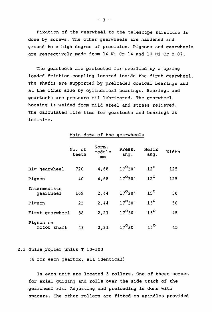
Main data of the gearwheels
No. of Norm. Press. Helix module Width teeth ang. ang. rom
Big gearwheel 720 4,68 17°30' 12° 125
Pignon 40 4,68 17°30' 12° 125
Intermediate gearwheel 169 2,44 17°30' 15° 50
Pignon 25 2,44 17°30' 15° 50
First gearwheel 88 2,21 17°30' 15° 45
Pignon on 17°30' 15° motor shaft 43 2,21 45
2.3 Guide roller units T 10-103
(4 for each gearbox, all identical)
In each unit are located 3 rollers. One of these serves
for axial guiding and rolls over the side track of the
gearwheel rim. Adjusting and preloading is done with
spacers. The other rollers are fitted on spindles provided
- 4 -
with excenters. The rollers at the gearteeth side are adjusted
at the MAAG factory to obtain the correct gear teeth clearance.
The position of these excenters always should remain the
same. The nuts for that reason are locked by pins. The oppo
site rollers are also fitted on excenter spindles, which
serve for preloading. The preload moment on the spindles
is 3 mkp. All spindles are iocked by special locking screws
located at the side.
2.4 Moment arms T 10-104 and T 11-104
(Basically the same for both telescope ax~s)
The moment arms transmit the teeth force to the telescope
structure. The supports on the telescope structure are
different, as well as the length of the "floating" parts.
The ball heads however are identical. Each ball head is
preloaded by a belleville spring washer unit. These units
give a preload of about 2500 kg in each of the ball heads
to eliminate backlash in the ball units. A small moment arm
is located between gearwheel cover and gearbox.
2.5 Gearbox upperparts T 10-105 and TIl-lOS
(Identical for both gearboxes)
These parts are welded from mild steel sheets and are
stress relieved. At the flange side there is a provision to
fit a flexible rubber seal. Four guide roller units are
located in each part, and connected and located by screws
resp. adjusting pins. To prevent oil loss, each unit is
closed by a steel cover. At one of the short sides, there
is a provision to fix the moment arms. At the center the
incremental encoder is located.

- 5 -
2.6 Gear cover T 10-106 and T 11-106
(These parts are mainly equal)
The cover is bolted together from two pieces. Both are
welded from thin steel sheets. At the center there are two
steel rings. These rings serve as bearings for the gear cover.
The bearing surfaces are provided with a bronze layer.
No teeth forces are loading this part. There are only forces
on the bearings coming from the weight and from friction.
The bearing rings are provided at its· inner side with an
oil catch. It is possible to demount the covers from the
telescope without demounting bigger telescope parts. Friction
forces from the bearings are led to the gearbox upper part
by a small moment arm.
The oil returns at both gearcoversare different. At the
declination axis the gearcover is provided with an oil return
that serves in case the telescope is nearing the 6 hour
position.
2.7 Gearbox bottom parts T 10-107 and T 11-107
(Besides a small detail these parts are equal for both axes)
At the declination axis there is an oil return at the side.
At the polar axis the oil flows directly to the oil tank that
is located underneath this part.
Both parts, upper- and bottom, together form the gearbox
that rolls over the main gearwheel by the guide rollers.
The Heidenhain encoder and Siemens encoder are located
near the flange connection of both gearbox parts.
- 6 -
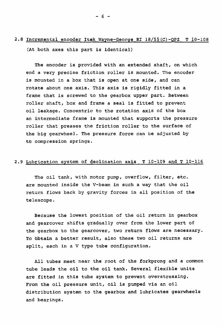
2.B Incremental encoder Itek Wayne-George RI lB/55(C)-QPZ T 10-10B
(At both axes this part is identical)
The encoder is provided with an extended shaft, on which
end a very precise friction roller is mounted. The encoder
is mounted in a box that is open at one side, and can
rotate about one axis. This axis is rigidly fitted in a
frame that is screwed to the gearbox upper part. Between
roller shaft, box and frame a seal is fitted to prevent
oil leakage. Concentric to the rotation axis of the box
an intermediate frame is mounted that supports the pressure
roller that presses the friction roller to the surface of
the big gearwheel. The pressure force can be adjusted by
to .compression springs.
2.9 Lubrication system of declination axis T 10-109 and T 10-116
The oil tank, with motor pump, overflow, filter, etc.
are mounted inside the V-beam in such a way that the oil
return flows back by gravity forces in all position of the
telescope.
Because the lowest position of the oil return in gearbox
and gearcover shifts gradually over from the lower part of
the gearbox to the gearcover, two return flows are necessary.
To bbtain a better result, also these two oil returns are
split, each in a V type tube configuration.
All tubes meet near the root of the forkprong and a common
tube leads the oil to the oil tank. Several flexible units
are fitted in this tube system to prevent overstressing.
From the oil pressure unit, oil is pumped via an oil
distribution system to the gearbox and lubricates gearwheels
and bearings.

- 7 -
Parts of the lubrication system are:
1) 1 luboil pump 5) oil distributor
2) 1 pressure regulator 6) oil tank
3) 1 ArIon filter 7) level indicator
4) 1 pressure indicator 8) drain.
with el. contact
The oil pump (of the gearwheel type, make MAAG) is driven
by a Landert motor. The normal pressure is 1,5 kp/cm2 .
This pressure is regulated by a pressure regulator, which
is adjusted to the correct pressure. The oil pressure can
be seen on the pressure indicator, make Haenny, type 220V/IA,
and is provided with electrical contacts that cut off the 2 motor current when the pressure drops below 1,2 kp/cm .
The oil filter, make ArIon GA60, has a capacity to filter
an oil quantity of 60 l/min at 10 microns. The actual pump
capacity is 6 l/min, so there is a big oversize of the
filter. The filter is provided with clogging indicator.
The oil tank is provided with a level indicator.
2.10 Lubrication system of polar axis T 11-109
The lubrication system of the polar axis is in principle
the same as that at the declination axis. Its layout however
is much simpler, because the gearbox stays always in the
same position. The oil tank including pressure unit for that
reason could be mounted rigidly underneath the gearbox.
2.11 Transverse component reaction member;' T 11-110
This device compensates the side force on the gearbox,
that results from the component of the gravity forces parallel
to the polar axis.

- 8 -
This force can be adjusted to 200 kp by a nut and
screw spindle, that compresses a set of 38 Belleville
spring washers. The deflection is 13 rnrn for a force of
200 kp.
2.12 Heidenhain backup position encoder TIl-Ill
Encoder type Rod 1/45.7 with 72000 inc./rev. is driven
over a backlash free coupling from one of the pignons
acting on the big gearwheel and making a ratio 18:1 to it.
The same unit is fitted on the declination gearbox.
2.13 Counterweight declination axis T 10-112
This device has a similar function as T 11-110. Because
of the rotation of the gearbox in different positions, it
is necessary to apply a counterweight lever system.
It mainly consists of a square tube rigidly fixed
to the fork prong, that supports the counterweight. The
gearbox is fixed to it by a shaft provided by two ball
joints.
2.14 Position indicator Siemens V23463-KOlOl-Dl13 T 11-112
These units are equal at both axes and coupled to one
of the pignon shafts acting on the main gearwheel.
2.15 Arnortisseur T 10-113
This part is necessary to damp the vibrations in the
counterweight device T 10-112.
- 9 -
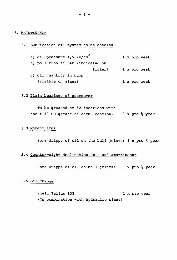
3. MAINTENANCE
3.1 Lubrication oil system to be checked
a) oil pressure 1,5 kp/cm 2
b) pollution filter (indicated on
filter)
c) oil quantity in pump
(visible on glass)
3.2 Plain bearings of gearcover
To be greased at 12 locations with
about 10 CC grease at each location.
3.3 Moment arms
1 x prl:) week
1 x pro week
1 x pro week
1 x pro ; year
Some dripps of oil on the ball joints: 1 x pro; year
3.4 Counterweight declination axis and arnortisseur
Some dripps of oil on ball joints: 1 x pro ; year
3.5 Oil change
Shell Tellus 133 ' 1 x pro year
(In combination with hydraulic plant)
- 10 -
4. MANUAL DRIVING OF THE GEARBOXES
When the motor current is cut off and it is for some
reason necessary to drive the gearboxes, this can be done
with a lever that fits to the hexagon on the extended motor
shaft. Before this, both friction brakes have to be disengaged
by the three MS screws at each brake. (It has to be made sure,
that the telescope is well balanced or protected for running
away, because the gearboxes are not self locking). For
manual drive it is normally not necessary to engage the luboil
pumps. After the manual drive the MS screws directly need
to be turned to the left sufficiently to be sure that the
brake can work correctly again.

- 11 -
5. DEMOUNTING PROCEDURE OF DECLINATION GEARBOX
- Put the telescope into the 12 hour position with tube
vertical and cut off the hydraulic oil of the declination
bearings.
- Disconnect the oil tubes, counterweight, cabling, etc.
- Close the open ends of oil tubes.
- Put both brakes into no brake position by right hand
rotations of the 3 MS screws (fig. 1).
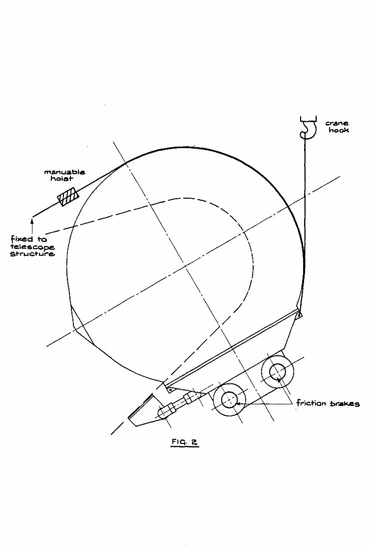
- Take over the weight of the gearbox from the moment
arm by manuable hoist (fig. 2).
- Demount the 2x4 M24 bolts of the moment arms. Take care
that all parts, spring units and spacers will be fitted in
the same position afterwards.
- Move the gearbox to the top side by crane and manuable
hoist (fig. 2 + fig. 3).
- Engage both brakes by left hand turns of the 3 MS screws
- Prevent any rotation between gearbox and gearwheel cover
by tightening both M12 screws at the corners.
- Demount the small moment arm between gearbox and gearwheel
cover.
- Demount the rubber seal between gearbox and gearcover.
- 12 -
- Demount the incremental encoder, after diminishing the
force on the friction roller by relieving both compression
springs. Both adjusting screws always should remain in the
same position.
- Take off the covers of the guide rollers.
- Turn of each roller unit the excenter spindle which
is nearest to the declination axis (in total 4) by left hand
rotation. (fig. 4)
Before this, the four M8 locking screws have to be
slackened as well as ~he four M30 nuts.
Remark: the four other nuts M30 are locked by pins ------and never should be unlocked.
- Lift the gearbox very smoothly, over a very small distance,
just enough to take over the load from the guide rollers. (fig. 5)
It is advisable, for getting this small lift, to use a manuable
hoist of 2 tons hanging on the dome crane. The gearbox should be
lifted as indicated. Four cables are fixed to the upper lifting
ears of the gearbox and at the other sides to the hook of the
manuable hoist. The second manuable hoist with a capacity of
0,5 ton is fixed to the drive motors and horked on the 2 tons
manuable hoist. With this arrangement smooth lifting and adjusting
is possible.
- Demount the four guiding roller units from the gearbox.
- Lift the gearbox from the big gearwheel and put it on two
supports. Take care that the fragile frame for the connection
of the rubber strips do not touch the supports. Positioning
on the supports should be done by means of two steel bars
through the four lower lifting ears. Each bar is supported
at its end by two wooden blocks of sufficient thickness to keep
the frame free from the supports. (fig. 6)

- 13 -
- Close the gearwheel cover by its steel protection against
dust and mechanical damage.
6. DEMOUNTING PROCEDURE OF POLAR AXIS GEARBOX (see also declo axis)
- Demount parts of the existing floor structure near the
gearbox and make an auxiliary floor.
- Disconnect moment arm, transverse component reaction
member, cabling, etc.
- Put the.brakes into no brake position by right hand
rotation of the three M5 screws.
- Move the gearbox to the top side by crane and manuable
hoist.
- Engage both brakes by left hand turns of the three M5 screws.
- Prevent any rotation between gearbox and gearwheel cover
by tightening both M12 screws at the corners.
- Demount the small moment arm between gearbox and
gearwheel cover.
- Demount rubber seal between gearbox and gearcover.
- Demount incremental encoder after diminishing the force
on the friction roller by relieving both compression springs.
- Take off the covers of the guide rollers.
- 14 -
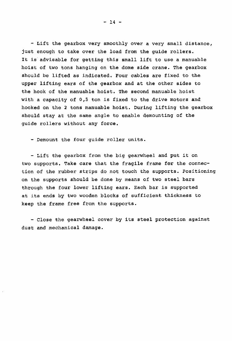
- Lift the gearbox very smoothly over a very small distance,
just enough to take over the load from the guide rollers.
It is' advisable for getting this small lift to use a manuable
hoist of two tons hanging on the dome side crane. The gearbox
should be lifted as indicated. Four cables are fixed to the
upper lifting ears of the gearbox and at the other sides to
the hook of the manuable hoist. The second manuable hoist
with a capacity of 0,5 ton is fixed to the drive motors and
hooked on the 2 tons manuable hoist. During lifting the gearbox
should stay at the same angle to enable demounting of the
guide rollers without any force.
- Demount the four guide roller units.
- Lift the gearbox from the big gearwheel and put it on
two supports. Take care that the fragile frame for the connec
tion of the rubber strips do not touch the supports. Positioning
on the supports should be done by means of two steel bars
through the four lower lifting ears. Each bar is supported
at its ends by two wooden blocks of sufficient thickness to
keep the frame free from the supports.
- Close the gearwheel cover by its steel protection against
dust and mechanical damage.

- 15 -
7. MOUNTING PROCEDURE OF THE DECLINATION- AND POLAR AXIS GEARBOX
This should be done in the opposite sequence as described
in the demounting procedure (see also the figures). Care has
to be given to the following:
- Positioning of the gearbox, before placing it on 'the
big gearwheel, should be done very carefull and at the
correct angle. This means the flanges of gearbox and
gearwheel cover should be parallel and the two pignons
should meet the big gearwheel correctly. To do this,
the gearbox should be lowered with small steps within one
millimeter, at the same time observing the approach of the
gears. Stop lowering just before (±O,5mm) the gearteeth are
totally engaged in each other.
- Fit the guiding roller units (each one has its own
number) to the gearbox, fit the dowels and tighten the
six fixation screws.
- Lower the gearbox until the full weight comes on the
four rollers which are located on the still locked spindles.
- Preload the opposite roller spindle (in total: four)
with a torque of 3,5 kpm at its inner hexagon.
- Lock the spindle with its M30 nut (prevent rotation
of the spindle by holding it on the 'inner hexagon).
- Lock the spindle (second lock) with the M8 screw.
- Fit the rubber seal after once more checking the
parallelity of the flanges of gearbox and gearwheel cover.
For the rubber seal fitting a special procedure is worked
out in detail on page 17.
- 16 -
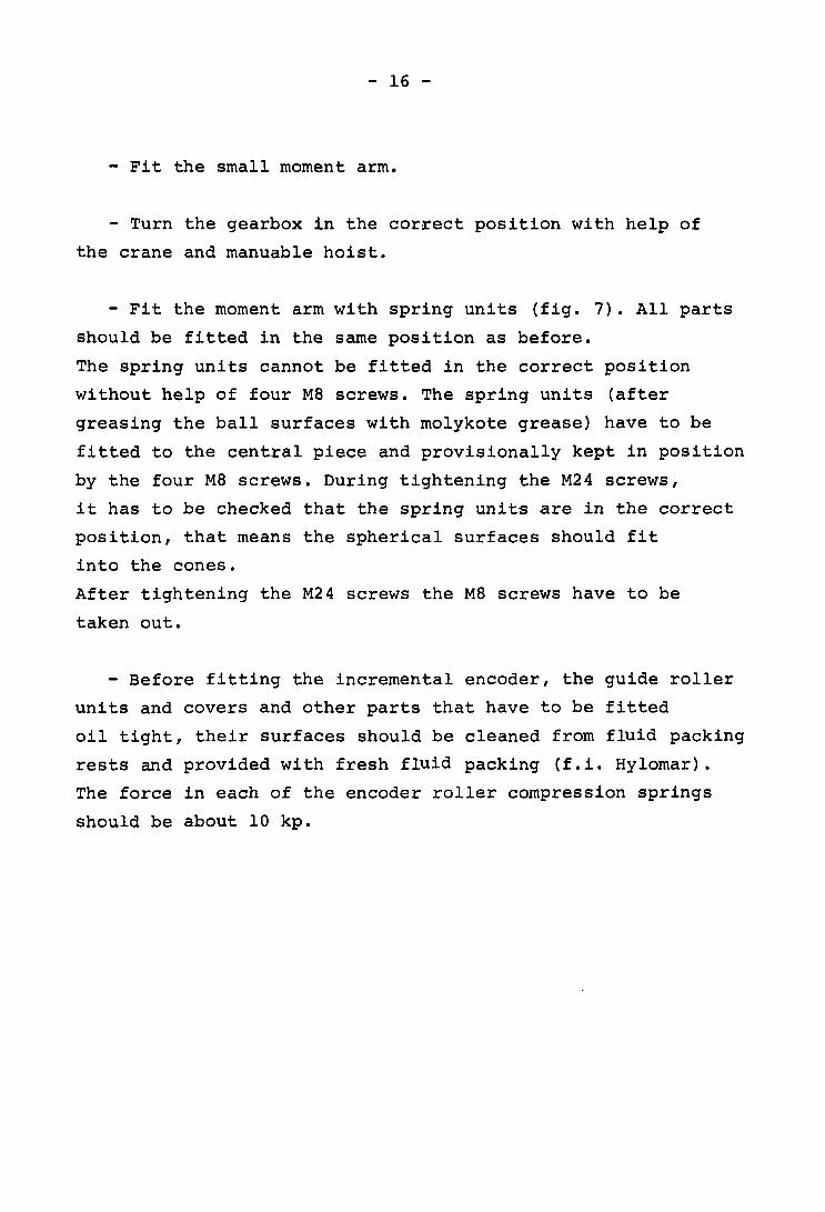
- Fit the small moment arm.
- Turn the gearbox in the correct position with help of
the crane and manuable hoist.
- Fit the moment arm with spring units (fig. 7). All parts
should be fitted in the same position as before.
The spring units cannot be fitted in the correct position
without help of four M8 screws. The spring units (after
greasing the ball surfaces with molykote grease) have to be
fitted to the central piece and provisionally kept in position
by the four M8 screws. During tightening the M24 screws,
it has to be checked that the spring units are in the correct
position, that means the spherical surfaces should fit
into the cones.
After tightening the M24 screws the M8 screws have to be
taken out.
- Before fitting the incremental encoder, the guide roller
units and covers and other parts that have to be fitted
oil tight, their surfaces should be cleaned from fluid packing
rests and provided with fresh fluid packing (f.i. Hylomar).
The force in each of the encoder roller compression springs
should be about 10 kp.

- 17 -
8. REPLACEMENT OF THE NITRIL RUBBER SEAL BETWEEN GEARBOX
AND GEARWHEEL COVER AT THE DECLINATION AXIS
(Before starting this should be read completely)
Dimensions: 27 x 4 rnrn, length ± 5,5 m
Deliverer: Angst & Pfister
Type of rubber: Nitril rubber.
The rubber seal can be cut from a standard rubber sheet.
This quality is highly oil resistant; and is of the same
quality as that of standard 'Sirnrnerring' type oil seals.
The life time of this seal is many years and cannot be
predicted. .
Replacement of the seal is possible on the telescope,
in the 12 hour position, with the tube vertical or somewhat
inclined to the north. Some cabling and oil tubes should be
demounted before starting.
Fixation of the rubber seal is done by steel strips, that
press the rubber to gearbox and gearwheel cover. For this,
M4 screws are used. The steel strips are marked and should be
replaced in the same position.
The holes in the rubber seal for the M4 screws have to be
drilled with special made hollow steel drills, as described
hereafter.
It is important to know that the most critical part of
the seal is at the lower short side of the gearbox. At the
other short side, no oil ever will corne. For that reason,
both free ends should meet at that side.
- 18 -
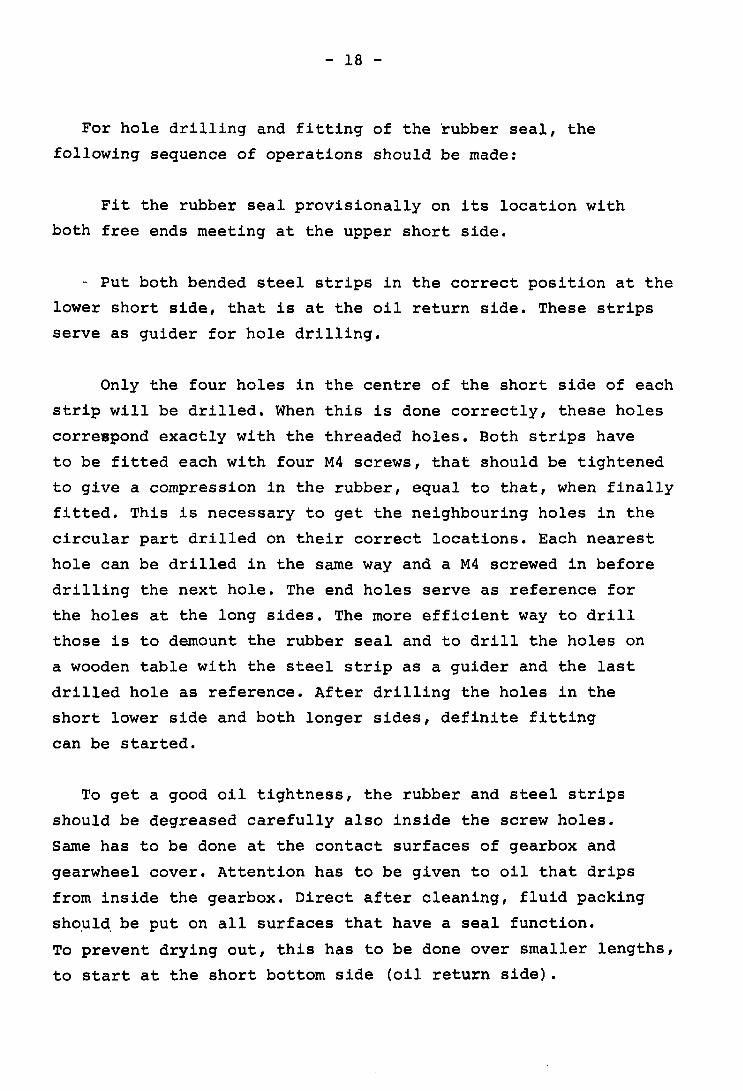
For hole drilling and fitting of the ~ubber seal, the
following sequence of operations should be made:
Fit the rubber seal provisionally on its location with
both free ends meeting at the upper short side.
- Put both bended steel strips in the correct position at the
lower short side, that is at the oil return side. These strips
serve as guider for hole drilling.
Only the four holes in the centre of the short side of each
strip will be drilled. When this is done correctly, these holes
correspond exactly with the threaded holes. Both strips have
to be fitted each with four M4 screws, that should be tightened
to give a compression in the rubber, equal to that, when finally
fitted. This is necessary to get the neighbouring holes in the
circular part drilled on their correct locations. Each nearest
hole can be drilled in the same way and a M4 screwed in before
drilling the next hole. The end holes serve as reference for
the holes at the long sides. The more efficient way to drill
those is to demount the rubber seal and to drill the holes on
a wooden table with the steel strip as a guider and the last
drilled hole as reference. After drilling the holes in the
short lower side and both longer sides, definite fitting
can be started.
To get a good oil tightness, the rubber and steel strips
should be degreased carefully also inside the screw holes.
Same has to be done at the contact surfaces of gearbox and
gearwheel cover. Attention has to be given to oil that drips
from inside the gearbox. Direct after cleaning, fluid packing
shoul~ be put on all surfaces that have a seal function.
To prevent drying out, this has to be done over smaller lengths,
to start at the short bottom side (oil return side).
- 19 -
Fitting of the bended strips has to be done in the same
way as during hole drilling to continue lateron with the
long sides. Drilling and fitting of the holes at the other
short side can be done in the same way as at the other side
starting in the center of the straight part and going to
both ends. The rubber ends have to be cut to the correct
length, that they come close together. It is not necessary
to put fluid packing in this region, because no oil will come
at that spot. The rubber seal should be fitted without tension.
Tension results in oval holes that may result in oil leakage.
The M4 screws,if they should be replaced,should be taken
exactly in the same length.
9. REPLACEMENT OF THE NITRIL RUBBER SEAL BETWEEN GEARBOX AND
GEARWHEEL COVER AT THE POLAR AXIS
(See also procedure declination axis)
The rubber seal is identical to that of the declination
axis. Both ends should meet at the longer upper side and
preferable excentric, near the short bended strips. The
critical side is the lower long side with the lower parts
of the short sides. On the top side no oil will be inside the
gearbox.
The sequence of hole drilling and fitting is different from
the declination axis, and should be started at the lower long
side. This can be done on a wooden table with help of the
proper steel strips.
After this, the seal has to be fitted provisionally to the
gearbox and gearwheel cover, the side holes should be drilled
with help of the bended strips, in the same way as at the
declination axis, starting with the 2x4 holes at the center
- 20 -
fitting 2x4 M4 screws firmly, etc.
After this, the holes at the upper side can be drilled
(after demounting the seal on a wooden table using the
last holes as a reference).
Final fixation has to be done after carefull cleaning,
same as at the declination axis, and screws fitting in the
same sequence as before.
10. DEMOUNTING OF THE MOTOR ASSEMBLY T 10-101
This can be done in 4 steps: brake, tachometer, motor and
shaft.
Brake
Demount 6 screws M6 at the fixation flange (after disconnec
ting the cabling). The brake than can be moved easily from
the shaft. The brake shaft can be demounted by 6 screws
MB x 25 (and eventually by slackening the 6 radial screws
MB x 30).
Tachometer
Demounting of the tRchometer has to be done in a special
sequence in order not to destroy the magnetism of the stator.
Lock the statorring (by small force) provisionally h~~screw lB.
Demount carefully brush ring 21 and insolator ring 20.
Demount the fixation screws for the stator ring 19.
Fit the keeper ring at the place of the insolator ring 20.
Demount the locking nut from the motor shaft.
Pull off carefully cover 09. At the same time stator with
keeper ring and rotor with commutator will be pushed off.
Stator with keeper ring can be taken out from 09, after
slackening screw lB. The keeper ring has to stay at the
- 21 -
stator until during the next complete fitting the rotor
is located and remains inside the stator.
Motor
Demounting of the motor has to be done in a special sequence
in order not to destroy the magnetism of the stator.
Press the auxiliary poles (carefully) to the rotor by the
fixation screws.
Slacken the 6 fixation screws M8 between rotor and shaft.
Fit the shipping clamp between stator" housing and rotor.
Slacken the 8 fixation screws M12 between stator~housing
and gearbox.
Motor shaft
During demounting and mounting care has to be taken
not to damage the oil seal and other parts by rough handling.
The weight of the shaft is about 35 kg. The shaft can be
taken out after demounting 6 screws M8 x 40 and 4 screws
M8 x 30 near the conical bearing.
Due to its inclined position (at the polar axis), the
shaft can slide out with a force of about 20 kg. This
should be avoided. Demounting only can be done, when care
is taken, that neither the gearteeth nor any other part
will hit the oil seal. This can be done by carefull demoun"ting
by hand, with help of a tube with diameter of 58 rom, that
fits into the hollow shaft.

i + a ~
: .. ~ -t_ ~ :. E .Q
CJN~ C
iJ.~ .,~
~t~~ lot-~'O '~:l0 ~~ J: L II) ue lJ
~i~.a \11. t.s: Z ~'" (J\
~~U:'" tl) 01:
-• a -u.
manuable haler
--fi,ced to -te.\escope. structure.
Flq.2.
cr.ane hook
~7"--~-- fric.tion b.-.. kes

cov .... guide
MI2 &crew --"'&".J
rt'1at1uablQ. nois","
/
\ \
FIQ,3
ir1Cne.me.Mt-.a1 encoder
$rna\l moment- arm
spr-'lnc::JS
r-ubber- seal

~ '-.91~ ~ 1]. eu 5 'n.~ en ~ 0" , (J2 s: '0. .-.- + :J. L.&. cr t~
J ~ c: ,
Q) L- a :1 ~~ ct) (Q H tJ C J: I: -
~ ,
I
. \9 -11.

riC.. 5
co .... anA hook
0.6 TOI"'\ manu:ab'e. hoist

n~~~~i~ stee.l bar-,..... wooden nlock
.' ".---.. frame.
FIe.. CO

m ~
~ 5 rD (f) .... I Q .-:t
2 )( / t\I " . cr -LL


![Wide Field Infrared Survey Telescope [WFIRST]: Telescope ... · the telescope exit pupil, which acts as the thermal/mechanical/optical interface between the telescope and imaging](https://img.dokumen.tips/doc/110x75/5f7661f13e5d4129fe68e696/wide-field-infrared-survey-telescope-wfirst-telescope-the-telescope-exit.jpg)


