Embed Size (px)
Citation preview

Major Leaps in Evolution of
IEEE 802.11 WLAN Technologies
Thomas A. KNEIDELRohde & SchwarzProduct ManagementMobile Radio Tester

Evolution of IEEE 802.11 WLAN Technologies 2
WLAN – Mayor Player in Wireless CommunicationsHealthcare AutomotiveWearables Smart CitiesSmart Homes
Smart Buildings LAN Retail …..Agriculture
Anything that benefits from network connection will be connected

IEEE Standard description Release date
802.11 1-2 Mbit/s, 2.4 – 2.485 GHz RF and IRAll other standards below are Ammendments (Except 802.11f and 802.11t)
1997
802.11a 54 Mbit/s, 5GHz, OFDM 1999
802.11b DSSS, CCK, 11 Mbit/s, 2.4 GHz 1999
802.11c Bridge operation procedures (not used) 1997
802.11d International (country-to-country) roaming extensions 2001
802.11e QoS and VoIP including packet bursting 2004
802.11f Roaming with IAPP (Inter Access Point Protocol) 2003
802.11g 802.11b OFDM for 2.4 GHz 2003
802.11h DFS (dynamic frequency selection) and TPC (transmit power control) for 802.11a 2004
802.11i Enhanced Security 2004
802.11j Extensions for Japan, 4.9 – 5 GHz, 10 MHz BW 2004
802.11-2007 Incorporates all standards above 2007
The 802.11-2007 standard supersedes the 802.11 standard released 1997 and
incorporated all approved ammendments up to that point, ie 802.11a, 802.11g, 802.11j etc.
WLAN Standardisation 802.11-2007
Evolution of IEEE 802.11 WLAN Technologies 3
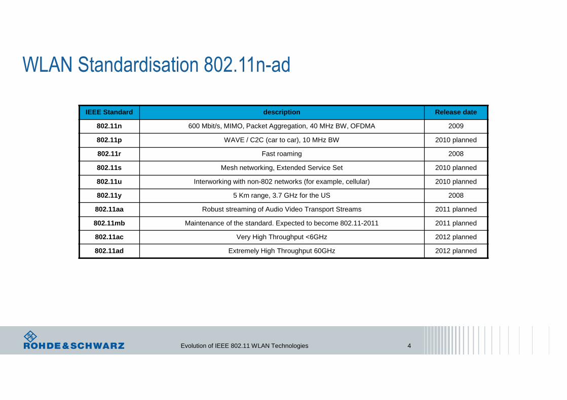
IEEE Standard description Release date
802.11n 600 Mbit/s, MIMO, Packet Aggregation, 40 MHz BW, OFDMA 2009
802.11p WAVE / C2C (car to car), 10 MHz BW 2010 planned
802.11r Fast roaming 2008
802.11s Mesh networking, Extended Service Set 2010 planned
802.11u Interworking with non-802 networks (for example, cellular) 2010 planned
802.11y 5 Km range, 3.7 GHz for the US 2008
802.11aa Robust streaming of Audio Video Transport Streams 2011 planned
802.11mb Maintenance of the standard. Expected to become 802.11-2011 2011 planned
802.11ac Very High Throughput <6GHz 2012 planned
802.11ad Extremely High Throughput 60GHz 2012 planned
WLAN Standardisation 802.11n-ad
Evolution of IEEE 802.11 WLAN Technologies 4
Evolution of IEEE 802.11 WLAN Technologies 5
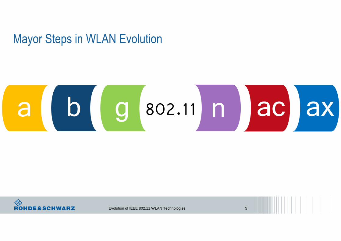
Mayor Steps in WLAN Evolution
a b g n ac ax802.11

IEEE 802.11bSingle Carrier Transmission
a b g n ac ax802.11
• Direct Sequence Spread Spectrum (DSSS)Complimentary Code Keying (CCK) Technique
• @ 2.4 GHz
• Support of 4 data rates from 1 to 11 Mbps
Evolution of IEEE 802.11 WLAN Technologies 6

Phase changePhase change0 � 01 � π
1 bit input1 MBit/s
11 BPSK chips output@ 11 MHz
Barker sequence+1, -1, +1, +1, -1, +1, +1, +1, -1, -1, -1Barker sequence+1, -1, +1, +1, -1, +1, +1, +1, -1, -1, -1
DBPSK
2 bits input2 MBit/s
Phase changePhase change00 � 001 � π/211 � π10 � -π/2
11 QPSK chips output(complex) @ 11 MHz
Barker sequence+1, -1, +1, +1, -1, +1, +1, +1, -1, -1, -1Barker sequence+1, -1, +1, +1, -1, +1, +1, +1, -1, -1, -1DQPSK
1 Mbps
2 Mbps
DSSS / Spreading with Baker Code1 and 2 Mbps
Occupied Bandwidth: 22 MHz
Evolution of IEEE 802.11 WLAN Technologies 7

DSSS / Spreading with Baker CodeIntersymbol Interference Protection
The 11 Chip Baker code autocorrelation function
High immunity of the system to multipath interference and collisions with other DSSS signals
Chip rate: 11 McpsChip Size: 11Chip duration: 90.9 ns
Multipath delays between 1 and 10 chips (90.9 ns to 909 ns) are not of concern
Assuming a propagation speed of 3 · 108 m/s
→ Path difference of about 27 to 272 meters
Code length of 11→ Process gain: 10.41 dB
10 log (code length)
→ Presence of informationeven below noise level
Evolution of IEEE 802.11 WLAN Technologies 8

CCK – Complementary Code Keying5.5 Mbps and 11 Mbps
4 bit Block
Transmitter
Data
DQPSKPhaseRotate
one of four, 8 bit code words
Bit stream
IEEE 802.11b 8 QPSK chips output at 5.5 Mbps
8 bit Block
Transmitter
Data
DQPSKPhaseRotate
one of 64, 8 bit code words
Bit stream
IEEE 802.11b 8 QPSK chips output at 11 Mbps
Chip rate: 11 McpsChip Size: 8Chip duration: 90.9 ns
Evolution of IEEE 802.11 WLAN Technologies 9

Evolution of IEEE 802.11 WLAN Technologies 10
Up to 14 WLAN Channels @ 2.4 GHz Band
Evolution of IEEE 802.11 WLAN Technologies 11
a b g n ac ax802.11
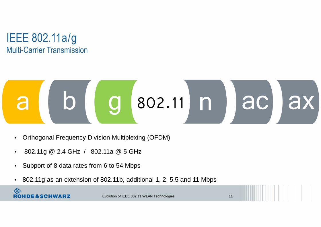
• Orthogonal Frequency Division Multiplexing (OFDM)
• 802.11g @ 2.4 GHz / 802.11a @ 5 GHz
• Support of 8 data rates from 6 to 54 Mbps
• 802.11g as an extension of 802.11b, additional 1, 2, 5.5 and 11 Mbps
IEEE 802.11a/gMulti-Carrier Transmission

Evolution of IEEE 802.11 WLAN Technologies 12
Single Carrier Modulation: Multipath Interference Sensitivity
Problem of multipath interference with one carrier:
TransmitterSignal
t
Multipath interference when symbol duration shorter than delay spread
Delay Delay spread
ReceiverSignal
t
Limitation of Single Carrier modulation – as soon as symbol rate increases→ symbol interval becomes shorter than the delay spread.
Solution : Multiple low-rate carriers instead of a single high-rate carrier
Decreasing the symbol rate and increasing the number of carriers
t
Symbol C0 Symbol C1 Symbol C2
Symbol C0 Symbol C1 Symbol C2
Symbol C0 Symbol C1 Symbol C2
delay
delay

Evolution of IEEE 802.11 WLAN Technologies 13
Multichannel System – FDM SystemConventional Multichannel System
Non Overlapping Adjacent Channels.
Channels separated by more than their two sided bandwidth
OFDM Multichannel System
Higher Spectral efficiency compare to conventional FDM50% Overlap of Adjacent Channels
Channels separated by Half their two sided bandwidth
f
f
Evolution of IEEE 802.11 WLAN Technologies 14
f
1/TS
f0 f2f1
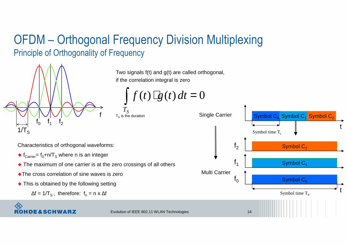
Characteristics of orthogonal waveforms:
� fCarrier= f0+n/TS where n is an integer
� The maximum of one carrier is at the zero crossings of all others
�The cross correlation of sine waves is zero
� This is obtained by the following setting
∆f = 1/TS , therefore: fn = n x ∆f
OFDM – Orthogonal Frequency Division MultiplexingPrinciple of Orthogonality of Frequency
Two signals f(t) and g(t) are called orthogonal, if the correlation integral is zero
0)()( =⋅∫ dttgtfST
TS is the duration Single Carrier Symbol C0 Symbol C1 Symbol C2
tSymbol time Ts
Symbol C1f1
Symbol C2f2
Symbol C0
tSymbol time TS’
f0Multi Carrier

Evolution of IEEE 802.11 WLAN Technologies 15
• 48 Subcarriers for Data
• 4 Pilot carriers for Reference
• Channel distance 312.5 kHz
• 12 unused carriers as guard bands (left, center and right)
• Channel Spacing: 20 MHz
• Nominal/Occupied bandwidth of 16.6 MHz(48 + 4 + 1) x 312.5 kHz = 16.5625 MHz
• OFDM Symbol Duration: 3.2 µs // additional Guard Interval 800 ns
• Data carrier modulation: BPSK, QPSK, 16QAM, 64QAM
• Coding Rate: ½, 2/3, ¾
• Coded Data Rates: 6, 9, 12, 18, 24, 36, 48, 54 Mbps
• Center Carrier is not used
IEEE 802.11a/g: OFDM Sub-Carrier Structure
20 MHz
Channel divided into 64 sub-carriers

Evolution of IEEE 802.11 WLAN Technologies 16
-26
(fc) 0
+26
+21
+7
-7
-21
+24
+16
+12
+4
-4
-12
-16
-24
Sub
carr
ier In
dex
Time(in µs)
2 Long TrainingSequence Symbols
10 Short TrainingSequence Symbols
SIGNALSymbol
SERVICE+DataSymbol Data
SymbolLast DataSymbol
8.0 8.03.21.60.8 0.8
4.0
PLCP Preamble PCLP Header PSDU + Tail + Pad
GI2 GI GI GI GI GI
R=1/2BPSK
Rate is indicated in SIGNAL symbol
Pilots
Signal Detect.AGC, DiversitySelection
Coarse Freq.Offset Estimationtiming Synchronize
Channel and fine FrequencyOffset Estimation Rate length Service+ Data Data
SubCarriers
� Short Training Sequenceonly every 4th carrier is used
� Start of Frame Detection� Signal Strength Indication� Frequency Offset Resolution
� Long Training Sequence
� Channel Estimate� Fine Time Resolution
� Pilot Signals
� Carrier Tracking� Sample Clock Tracking
BPSK Modulation used in Preambles, Signal Symbol and Pilot Signals
Evolution of IEEE 802.11 WLAN Technologies 17
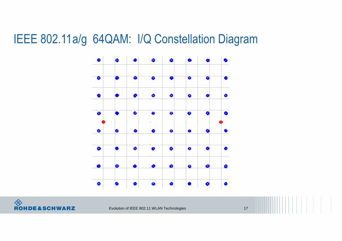
IEEE 802.11a/g 64QAM: I/Q Constellation Diagram

OFDM – Points of View
Advantages
ı High resistance to Multi-path Fading
ı Efficiently Deals With Channel Delay Spread
ı Enhanced Channel Capacity (use of bandwidth)
ı Adaptively Modifies Modulation Density
ı Robustness to Narrowband Interference
ı Scalable data rate
Disadvantages
ı Sensitive to Small Carrier Frequency Offsets
ı Higher Peak to Average Power Ratio (crest factor)
ı Sensitive to High Frequency Phase Noise
ı Sensitive to Sampling Clock Offsets
Equalization is simpler than in one carrier transmission
Principles of OFDM is known for more than 30 years. Implementation of OFDM-Baseband processing, which use Fast-Fourier-Transformation (FFT) in Modulation and inverse FFT (IFFT) in Demodulation, requires powerful signal processing, which was not available for a long time.
Evolution of IEEE 802.11 WLAN Technologies 18

Evolution of IEEE 802.11 WLAN Technologies 19
Inter-Symbol Interference (ISI) Symbol Smearing Due to Channel
t
t
Adjacent Symbols
Channel
h(t)
tt
x(t)
Symbol Distorted Symbol
y(t)
x(t) y(t)h(t)
t
Evolution of IEEE 802.11 WLAN Technologies 20
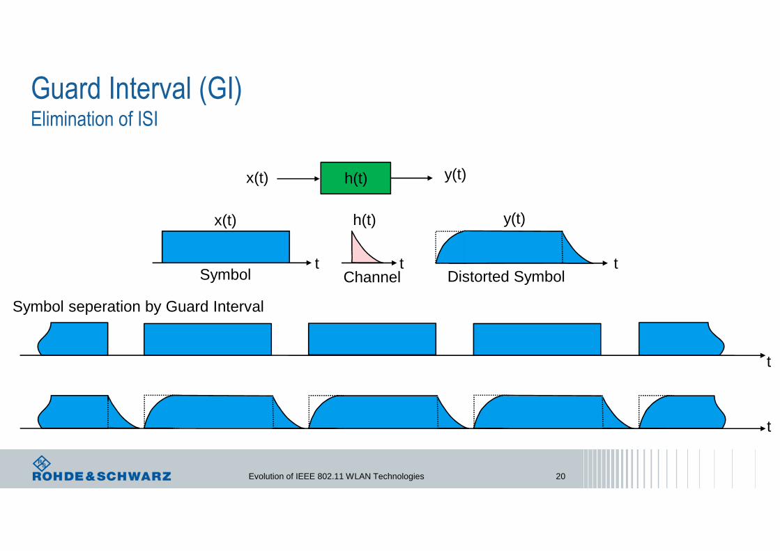
Guard Interval (GI)Elimination of ISI
Channel
h(t)
tt
x(t)
Symbol Distorted Symbol
y(t)
x(t) y(t)h(t)
t
t
t
Symbol seperation by Guard Interval

Evolution of IEEE 802.11 WLAN Technologies 21
�
�.� ��� 312.5kHz
Cyclic Prefix (CP)Better Alternative to Null GI
CP
0.8 µs 3.2 µs
OFDM Symbol
Channel
h(t)
tt
x(t)
Symbol Distorted Symbol
y(t)
x(t) y(t)h(t)
t
t
t
CP CP CP CP
Prefixing of symbol with a repetition of the end

Evolution of IEEE 802.11 WLAN Technologies 22
Up to 14 WLAN Channels @ 2.4 GHz Band
802.11 a / g (OFDM) 20 MHz Channel width – 16.5625 MHz only used by Sub-Carriers
22 MHz 20 MHz
Evolution of IEEE 802.11 WLAN Technologies 23
a b g n ac ax802.11
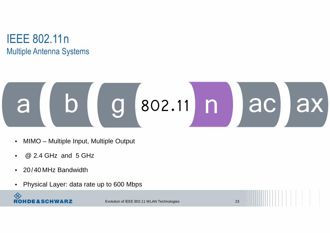
IEEE 802.11nMultiple Antenna Systems
• MIMO – Multiple Input, Multiple Output
• @ 2.4 GHz and 5 GHz
• 20 /40 MHz Bandwidth
• Physical Layer: data rate up to 600 Mbps

Evolution of IEEE 802.11 WLAN Technologies 24
• 52 Subcarriers for Data
• 4 Pilot carriers for Reference
• Channel distance 312.5kHz
• 8 unused carriers as guard bands (left, center and right)
• Channel Spacing: 20MHz / 40MHz
• Nominal/Occupied bandwidth of 16.6 MHz(52 + 4 + 1) x 312.5 kHz = 17.8125 MHz
• OFDM Symbol Duration: 3.2 µs // additional Guard Interval: 400ns or 800ns
• Data carrier modulation: BPSK, QPSK, 16QAM, 64QAM
• MIMO up to 4 spatial streams
IEEE 802.11n: OFDM Sub-Carrier Structure
20 MHz
… in case of 20 MHz bandwidth

Evolution of IEEE 802.11 WLAN Technologies 25
Multi-Path Progagation - Fading
Frequency shifts due to Doppler effects, caused by moving transmitters or receivers
Receiver detects signals with different time delays, levels and phases.
The higher the statistcal independence of the different fading channels, the better the achievable data transfer rate.
Uncorrelaeted, fading channels are required to distinguish the data streams coming from different transmit antennas

Evolution of IEEE 802.11 WLAN Technologies 26
MIMO Systems – Multiple Input, Multiple OutputSpatial Diversityincreases robustnes of data transmission
e.g. Alamouti space-time coding
MISOMultiple Input, Single Output
SIMOSingle Input, Multiple Output
Spatial Diversity
Spatial Multiplexingincreases data rates or channel capacity
Spatial Multiplexing
2x2 MIMO MU MIMO
Multi-User

Evolution of IEEE 802.11 WLAN Technologies 27
SIMO Systems – Rx Diversity
Received Signal Switched Diversity Maximum Ratio Combining
C = max (x, x´) C = (x + x´)
MRC
increases robustnes of data transmission
Spatial Diversityx
x´

Evolution of IEEE 802.11 WLAN Technologies 28
SIMO Systems – MRCMaximum Ratio Combining
1x2 MIMOSIMO
�� � ��� + ��
�� = ��� + ��
����
= ���� x + ����
Y=Hx+ N
increases robustnes of data transmission
Spatial Diversityx
x´
�� =��∗ �����
∗ ��
���� ��
�
TXAnt
RXAnt 1
n1
y1xLO
n2
y2
RXAnt 2
Estimatesx
e
MR
Cal
gorit
hm
Improved Signal-to-Noise Ratio �
�

Evolution of IEEE 802.11 WLAN Technologies 29
MISO Systems – Tx Diversitye.g. Alamouti // Space Time Block Coding
Spatial Diversity
2x1 MIMOMISO
Tx 1 Tx 2
Time t �� ��
Time t + T ��∗ ��
∗
increases robustnes of data transmission
TXAnt 1
TXAnt 2
RXAnt
n
y2 y1
HH
xe
2
Estimates
-x2*
x1*
x1
x2
xe
Space-Time-Block
LOx1x2�� = �� �� + �� �� + ��
�� = �� ��∗ + �� ��
∗ + ��
����
= �� ����∗ ��
∗
����
+ ����
Y = H X + N
xe
1
���
= ���
+ ���
��+ ��#
���
= ���
+ ���
��+ ��#
Alamouti scheme has the same diversity as the two-branch maximum ration combining (MRC)
Improved Signal-to-Noise Ratio �
�

Evolution of IEEE 802.11 WLAN Technologies 30
MIMO Systems – Spatial Multiplexing
increases data rates or channel capacity
y = H x
�
�
�
�
�
�
1
2
m
1
2
n
h11
h21
h12h22
h1m hn1
hnm
m transmit antennas n receive antennas
h11 h12 h.. h1m
h21 h22 h.. h2m
h.. h.. h.. h.m
hn1 hn2 hn. hnm
H =
X Y
Channel Matrix

Evolution of IEEE 802.11 WLAN Technologies 31
MIMO Systems – Spatial Multiplexing
increases data rates or channel capacity
�� = ��� �� + ��� �� + ��
�� = ��� �� + ��� �� + ��
H = �11 �12�21 �22
Channel�1
�2 �2Tx antennas Rx antennas
� = Hx " n
+ ����
2x2 MIMO
��
��
��
�� ���
���
�1
h21

Evolution of IEEE 802.11 WLAN Technologies 32
Spatial Streams
Space-Time Streams TX antenna signals
Spa
tial –
Ant
enna
–M
appi
ng
ST
BC
Str
eam
Par
ser
FE
C e
ncod
erF
EC
enc
oder
Scr
ambl
er
Insert GI and Window
IDFTCSDConstellationmapper
Interleaver
Enc
oder
Par
ser
Insert GI and Window
IDFTConstellationmapper
Interleaver
Insert GI and Window
IDFTCSDConstellationmapper
Interleaver
Insert GI and Window
IDFTCSDConstellationmapper
Interleaver
Data
WLAN 11n Baseband Transmitter Model
CSD Cyclic Shift Diversity
Dire
ctM
appi
ng
Bea
mfo
rmin
g
- 400 ns
- 200 ns
- 600 ns

Beamforming
TX antenna signals
Insert GI and Window
IDFT
Insert GI and Window
IDFT
Insert GI and Window
IDFT
Insert GI and Window
IDFT
Spa
tial –
Ant
enna
–M
appi
ngD
irect
Map
ping
Bea
mfo
rmin
g
Beamforming steering matrix: %& is any matrix that improves the reception in the receiver based on some knowledge of the channel between the transmitter and the receiver
Spa
ce-T
ime
Str
eam
s
Antenna map matrix %&
802.11n introduced implicit and explicit beamforming, but did not clearly defined
It was not widely used
Evolution of IEEE 802.11 WLAN Technologies 33
Evolution of IEEE 802.11 WLAN Technologies 34
a b g n ac ax802.11
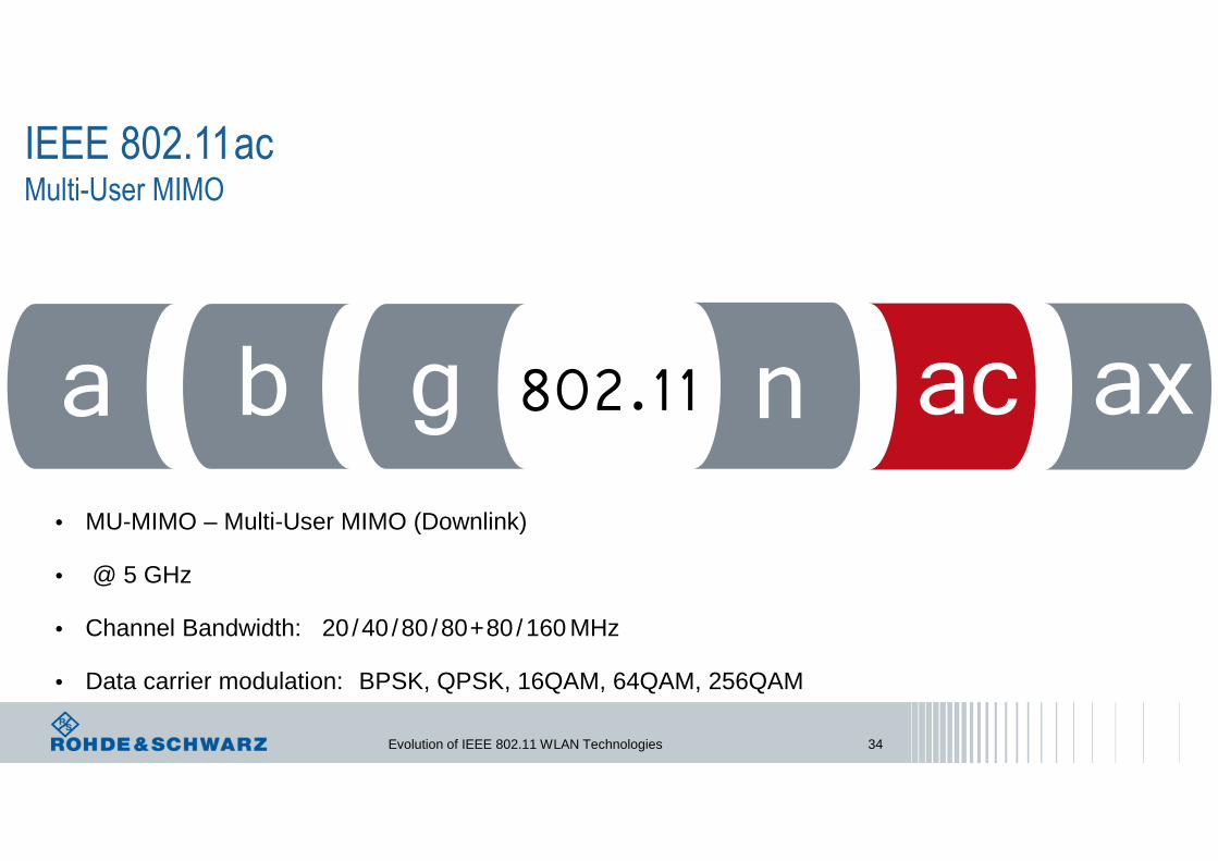
IEEE 802.11acMulti-User MIMO
• MU-MIMO – Multi-User MIMO (Downlink)
• @ 5 GHz
• Channel Bandwidth: 20 /40 /80 /80+80 /160 MHz
• Data carrier modulation: BPSK, QPSK, 16QAM, 64QAM, 256QAM
Evolution of IEEE 802.11 WLAN Technologies 35
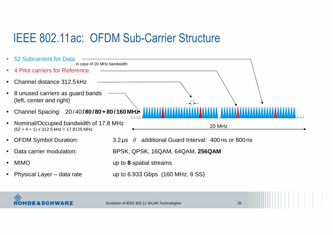
• 52 Subcarriers for Data
• 4 Pilot carriers for Reference
• Channel distance 312.5kHz
• 8 unused carriers as guard bands (left, center and right)
• Channel Spacing: 20 / 40 / 80 / 80+ 80 / 160MHz
• Nominal/Occupied bandwidth of 17.8 MHz(52 + 4 + 1) x 312.5 kHz = 17.8125 MHz
• OFDM Symbol Duration: 3.2 µs // additional Guard Interval: 400ns or 800ns
• Data carrier modulation: BPSK, QPSK, 16QAM, 64QAM, 256QAM
• MIMO up to 8 spatial streams
• Physical Layer – data rate up to 6.933 Gbps (160 MHz; 8 SS)
IEEE 802.11ac: OFDM Sub-Carrier Structure
20 MHz
… in case of 20 MHz bandwidth

Evolution of IEEE 802.11 WLAN Technologies 36
WLAN 11ac Channel Allocation36 40 44 48 52 56 60 64 10
0
104
108
112
116
120
124
128
132
136
140
IEEE channel #
20 MHz
40 MHz
80 MHz
160 MHz
5170MHz
5330MHz
5490MHz
5730MHz
144
149
153
157
161
165
5735MHz
5835MHz

Explicit Beamforming
802.11ac focus on use of explicit beamforming and discarded possibility of implicit beamforming.
Announcementsending soon sounding frames
Null Data Packet (NDP)Soundingin various directions
Report requestBeamforming Feedback'&-Matrix
Re-calibration of phase shift for each of the transmitted signal from each antennaReaching maximum signal strength at client
( → Beamforming steering matrix: %& )
Measures the channel martices
Implicit BeamformingAP measures the received upstream and based on the result derive the parameters for subsequent downstream beam
Evolution of IEEE 802.11 WLAN Technologies 37

MU-MIMO Systems – Spatial Multiplexingbased on Explicit Beamforming
Multi UserMU-MIMO beamforming addresses multiple users located in spatially diverse positions
MISO
MISO
MIMO
Null-steering transmit beamformers aim to maximize the received signal power in the direction of the intended receiver while substantially reducing the power impinging on the unintended receivers located in other directions.
Evolution of IEEE 802.11 WLAN Technologies 38
a b g n ac ax802.11
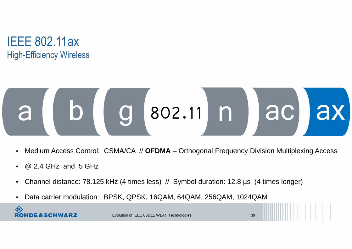
IEEE 802.11axHigh-Efficiency Wireless
• Medium Access Control: CSMA/CA // OFDMA – Orthogonal Frequency Division Multiplexing Access
• @ 2.4 GHz and 5 GHz
• Channel distance: 78.125 kHz (4 times less) // Symbol duration: 12.8 µs (4 times longer)
• Data carrier modulation: BPSK, QPSK, 16QAM, 64QAM, 256QAM, 1024QAM
Evolution of IEEE 802.11 WLAN Technologies 39

• 234 Subcarriers for Data
• 8 Pilot carriers for Reference
• Channel distance 78.125kHz
• 14 unused carriers as guard bands (6 left, 3 center and 5 right)
• Channel Spacing: 20 / 40 / 80 / 80+ 80 / 160MHz
• Nominal/Occupied bandwidth of 17.8 MHz(234 + 8 + 3) x 78.125 kHz = 19.140625 MHz
• OFDM Symbol Duration: 12.8 µs // additional Guard Interval: 0.8, 1.6, 3.2 µs
• Data carrier modulation: BPSK, QPSK, 16QAM, 64QAM, 256QAM, 1024QAM
• Coding BCC – Binary Convolutional Code // LDPC – Low-Density Parity-Check
• MIMO up to 8 spatial streams
• Physical Layer – data rate up to 9.6078 Gbps (160MHz, 8 SS)
IEEE 802.11ax: OFDM Sub-Carrier Structure
20 MHz
… in case of HE-SU 20 MHz bandwidth
Evolution of IEEE 802.11 WLAN Technologies 40
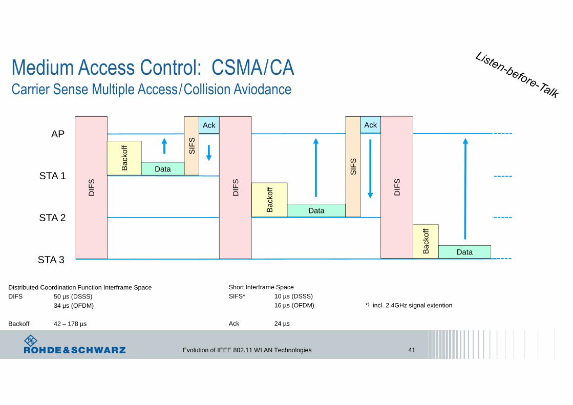
Medium Access Control: CSMA/CACarrier Sense Multiple Access/Collision Aviodance
AP
STA 1
STA 2
STA 3
SIF
S
Ack
DIF
S
Bac
koff
Bac
koff
Ack
Bac
koff
Data
Data
Data
Distributed Coordination Function Interframe SpaceDIFS 50 µs (DSSS)
34 µs (OFDM)
Backoff 42 – 178 µs
Short Interframe SpaceSIFS* 10 µs (DSSS)
16 µs (OFDM) *) incl. 2.4GHz signal extention
Ack 24 µs
SIF
S
DIF
S
DIF
S
Evolution of IEEE 802.11 WLAN Technologies 41
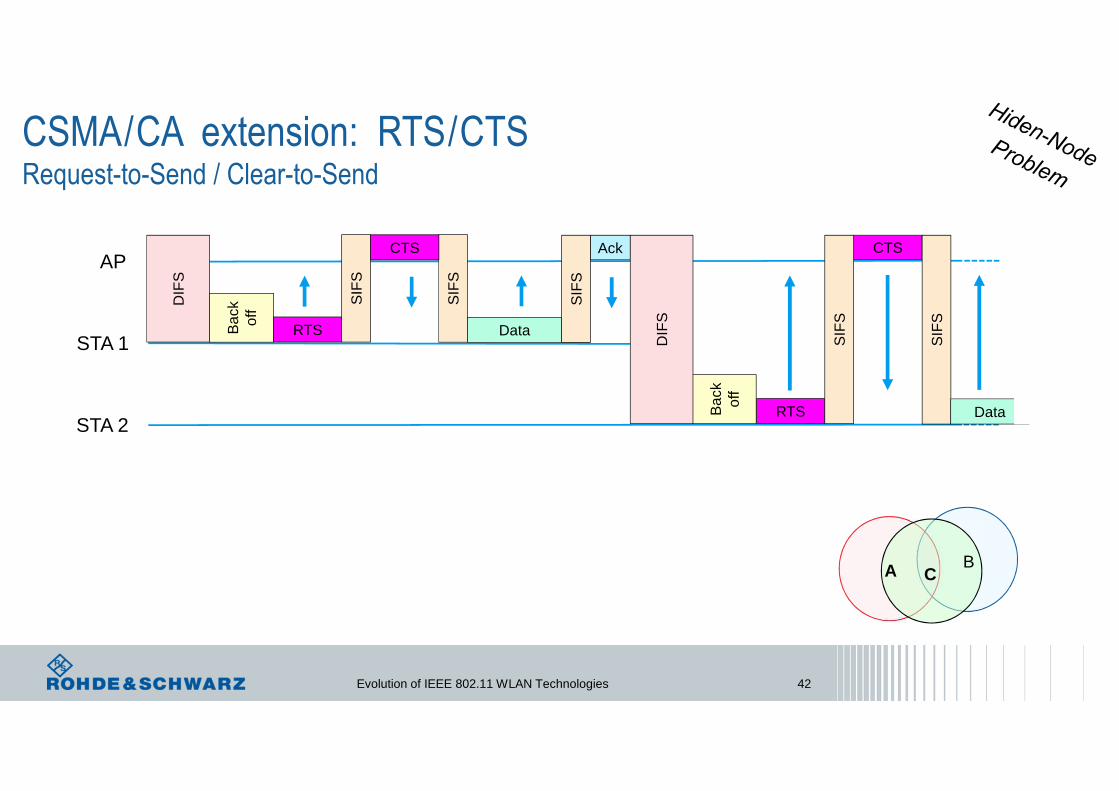
CSMA/CA extension: RTS/CTSRequest-to-Send / Clear-to-Send
AP
STA 1
STA 2S
IFS
Ack
DIF
S
Bac
kof
f
DataRTS
SIF
S
CTS
SIF
S
RTSBac
kof
f
CTS
DIF
S
SIF
S
SIF
S
Data
CBA
Evolution of IEEE 802.11 WLAN Technologies 42

IEEE 802.11ax: Multi-user Operations
STA1RTS
CTS ACK
STA2RTS
CTS ACK
AP
STA
STA1+2MU-RTS
CTS ACKSTA1+2
OFDMA
½ BW => 2x duration
Simultaneous Response
AP
Time saved
Evolution of IEEE 802.11 WLAN Technologies 43

Evolution of IEEE 802.11 WLAN Technologies 44
OFDMA = OFDM + FDMA
•••••••••
•••••••••
•••••••••
•••••••••
•••••••••
•••••••••
WLAN 11ac: OFDM allocates users in time domain only
WLAN 11ax: OFDMA allocates users in time and frequency domain
•••••••••
•••••••••
•••••••••
•••••••••
•••••••••
•••••••••
Time domain Time domain
Fre
quen
cy d
omai
n
Fre
quen
cydo
mai
n
User3
User3
User2
User2
User1
User1

Evolution of IEEE 802.11 WLAN Technologies 45
From single-user to multi-user OFDMAExample: 20 MHz bandwidth
RU1 RU2 RU3 RU4 13 13 RU6 RU7 RU8 RU9RU
RU1 RU2 RU3 RU4
RU1 RU2
SU 242RU1
13
1313
13
• Channel bandwidth isdivided into resource units, RU
• One RU belongs to oneuser. In the next timeslot, the RU may be anotheruser
• Each RU may have a different modulationscheme and/or codingrate
• RU size:26 -52 -
106 -242 -484 -996 -
2x996 - SubCarriers
Evolution of IEEE 802.11 WLAN Technologies 46
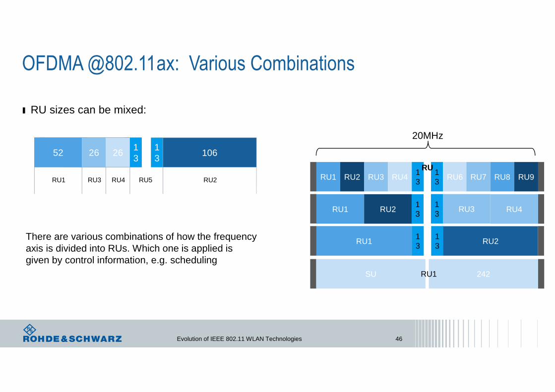
OFDMA @802.11ax: Various Combinations
There are various combinations of how the frequencyaxis is divided into RUs. Which one is applied isgiven by control information, e.g. scheduling
52 26 2613
13
106
RU1 RU3 RU4 RU2RU5
20MHz
RU1 RU2 RU3 RU413
13
RU6 RU7 RU8 RU9RU
RU1 RU2 RU3 RU4
RU1 RU2
SU 242RU1
13
13
13
13
ı RU sizes can be mixed:

Evolution of IEEE 802.11 WLAN Technologies 47
OFDMA @802.11ax: Multi-User DownLink
Ack
AP
STA 1
STA 2
STA 3
Data
Packet Protocol: HE-MUDL only
SIF
S
Ack
Ack
imm
edia
te U
L O
FD
MA
A
ck
OR
Ack
Ack
Ack
Blo
ck A
ck R
eque
st
SIF
S
Blo
ck A
ck R
eque
st
SIF
S
CTS
CTS
CTS
SIF
S
MURTS

Evolution of IEEE 802.11 WLAN Technologies 48
OFDMA @802.11ax: Multi-User UpLinkSynchronisation by Trigger Frame
Multi-User Operations are controlled by AP
Multi-User Uplink is initiated by Trigger Frame from AP
Trigger Frame includes:• Device IDs
• RU allocations, MCS, Number of
spatial streams, …
• Power Control
AckAP
STA 1
STA 2
STA 3Data
Data
Data
Trigger Frame
SIF
S
SIF
S
Packet Protocol: HE-TBUL only TB – Trigger Based
MU
-STA
Blo
ck A
ck

Evolution of IEEE 802.11 WLAN Technologies 49
OFDMA @802.11ax: Time of Departure Accuracy
Packet Protocol: HE-TBUL only
AckAP
STA 1
STA 2
STA 3
Data
Data
Trigger Frame
SIF
S
SIF
S
MU
-STA
Blo
ck A
ck
Specified Tolerance: ± 0.4 µs
Data

Evolution of IEEE 802.11 WLAN Technologies 50
OFDMA @802.11ax: Dynamic Power Control
AP
STA 1
STA 2
STA 3
Power differences between STAs in a UL MU transmission results in a degradation of the performance
Arrival power of different STAs at AP should be roughly the same
Need for Transmit Power Pre-Correction Transmit Power Control (TPC)
Reference: Target Receiver Signal Strength Indicator (RSSI) at the AP side.
AP reports its used transmit power and the expected Target RSSI together with each data-package
STA measures RSSI of received data-package and calculate its path loss
STA transmit signal with power equal to Target RSSI of AP plus calculated path loss.
If necessary AP send a appropriate command to each STA to increase or decrease their power levels
Class A Class B
Absolute transmit ± 3dB ± 9dBPower accuracy
RSSI measurement ± 2dB ± 5dBaccuracy
Evolution of IEEE 802.11 WLAN Technologies 51
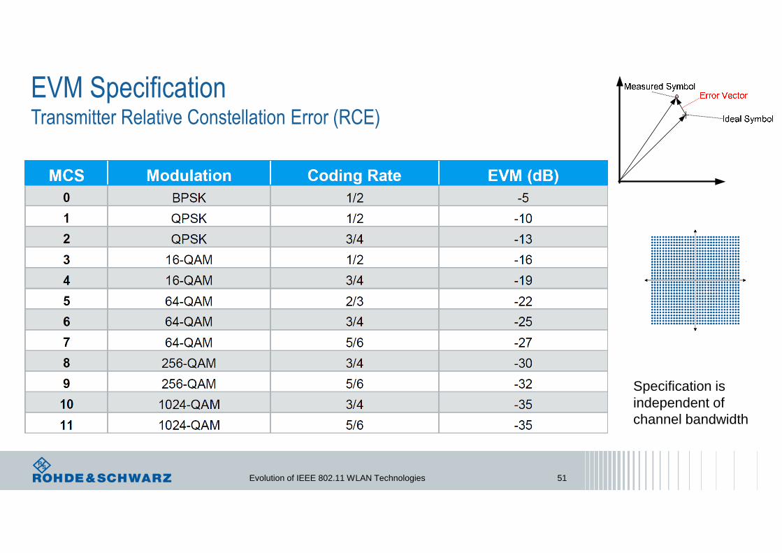
EVM SpecificationTransmitter Relative Constellation Error (RCE)
Specification is independent of channel bandwidth

Evolution of IEEE 802.11 WLAN Technologies 52
OFDMA @802.11ax: Unused Tone Error
Unused tone eror (In-band Emission) limit value for RU26.
For other RU sizes, different limit values and step widths apply.
Evolution of IEEE 802.11 WLAN Technologies 53
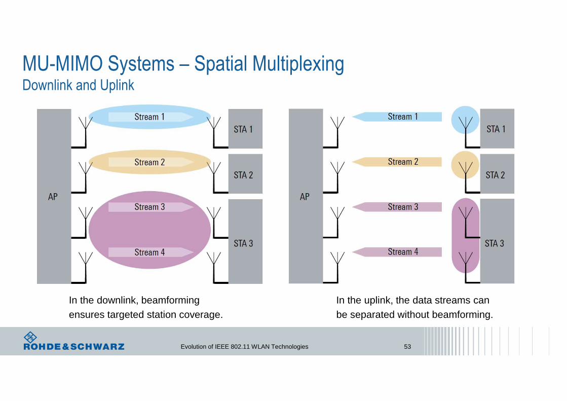
MU-MIMO Systems – Spatial MultiplexingDownlink and Uplink
In the downlink, beamforming ensures targeted station coverage.
In the uplink, the data streams can be separated without beamforming.
Evolution of IEEE 802.11 WLAN Technologies 54
Thank youfor your attention !