Embed Size (px)
Citation preview
Maintenance of Points and Crossing in Mega yard ,Some Untouched Features
BY –1.S.L.Ghosh 2.A.K.Shahi 3.A.P.Singh
4.S.K.Choubey
Paper Prepared under Guidance of Course Director Mr N.R.Kale AXEN I IRICEN Pune

Preamble
In this presentation It is tried to Keep our past experience gained during 26 Years of service beginning from grass root level worker,& proposals for rectification of such defects from our ends for achieving excellence in maintenance in mega yard and big yard including typical layout and Diamonds and Scissors also.
Contd.
- Points and crossings are vital & most weak part of track structure which requires baby care otherwise in long term it will lead to many accidents /interruptions to normal traffic ,if not maintained properly.
Para no. 237,317 & Para no.1413of IRPWM laid down the detailed procedure of Inspection ,maintenance , renewal &laying of PSC Layout as well as other types of points and crossings on various sleepers.

Contd. After introducing Fan shaped layout
in Indian Railways , protection to gauge and cross level obtained in points crossing zone, in safe and satisfactory manner limited to a certain extent, if nursing not done properly. After a long period, enjoying with PSC sleeper, say about 3 to 7 years, following weak area having severe defects detected .
Burr Formation On Stock Rail Due to plastic deformation and flow of
metal from gauge face corner Burr are formed which if not attended within time, leads to non setting of points and breakage/chipping of tongue rail. Existing method of burrs removal in vogue is by using chisel and sledge hammer.
This prevalent practice is clear-cut violation of handling instructions for 90UTS rails, and this may also leads to fracture of stock rail in long run.
We recommends use of rechargeable Cordless grinder with double battery for immediate removal of burrs.

Switch portion Weak Point Always first Joint of main line tongue
rail connecting to lead rail ,a bad alignment/ Low joint is observed and also a peak formed ,which is observed during OMS Run.
It is suggested ,that through Tongue rail which is situated on main line/straight side to lead rail may be welded with rail to eliminate the bad riding.

Switch portion Weak Point
Around sleeper no.21 and sleeper no. 22 (in 1 in 12 T/out), having spl. Bearing plate gauge becomes always slack and misalignment formed and peak is experienced.
To Avoid this defect and maintaining track geometry in order Existing Distance block to be modified at this Identified Location.
Defects In switch Portion
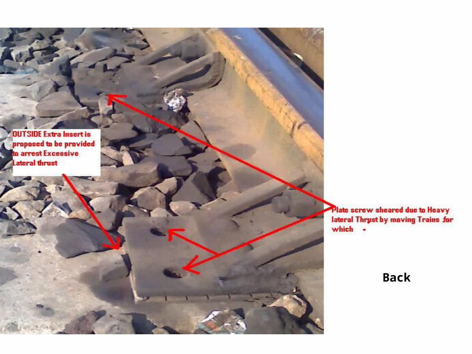
1.Plate screw RT T/3912 is used to hold the slide chair but problem of severe corrosion is faced and due to lateral thrust exerted by wheel of train, plate screw sheared and it is difficult to remove the broken Portion of the plate screw without any special arrangement.
To overcome with the problem of corrosion all the plate screw should be galvanized (It is also mentioned in the specification of Plate screw issued by RDSO) ,that railway may order the galvanization of Plate screw if necessity arises.
Defects Identified and Alteration Suggested, In switch Portion
2. The frequent greasing of plate screw should be done at suitable intervals (say like at 6 Month in corrosion prone area, and one year in non corrosion area) .
3. A planned through renewal of plate screw & GRSP also to be done according to “codal life of assets” at intervals of four years .This should be strictly followed in heavy density routes and all Busy yards.
Defects Identified and Alteration Suggested, In switch Portion
4. Like out side Inserts Provided on sleeper no 3,4 &5 of switch portion to minimize the lateral thrust of rolling stock wheels flange by attacking on switch entry, Outside Insert on both outer side of sleepers Up to heel block slide chairs should be provided .
5. The head of the plate screw is of square shank which corner oftenly rounded during tightening/ opening. It become very difficult to open the plate screw for periodical greasing/changing of slide chairs. The head of Plate screw should also be modified to Rectangular shape.
Back

Defects Identified and Alteration Suggested, In switch Portion
6. Housing of tongue rail is required to be done up to JOH at the time of initial laying .and It was also mentioned in para no 317(l) that at the time of renewal proper housing is to be ensured against the stock rail for the full length of the planning of switch without any external pressure being applied to keep in position .But due to inertia of tongue rail , practically it is not possible set the tongue rail after providing connection. For achieving full setting either 2nd pull rod with extra motor or Hydraulic SSD with electronic gap detection system should be provided.( As provided in advanced country)
It May be seen in the Next slide.
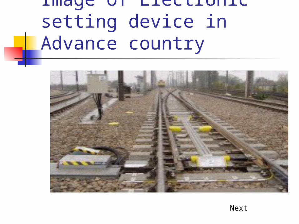
Image of Electronic setting device in Advance country
Next
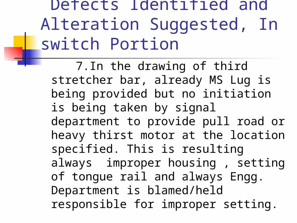
Defects Identified and Alteration Suggested, In switch Portion 7.In the drawing of third stretcher
bar, already MS Lug is being provided but no initiation is being taken by signal department to provide pull road or heavy thirst motor at the location specified. This is resulting always improper housing , setting of tongue rail and always Engg. Department is blamed/held responsible for improper setting.
Defects Identified and Alteration
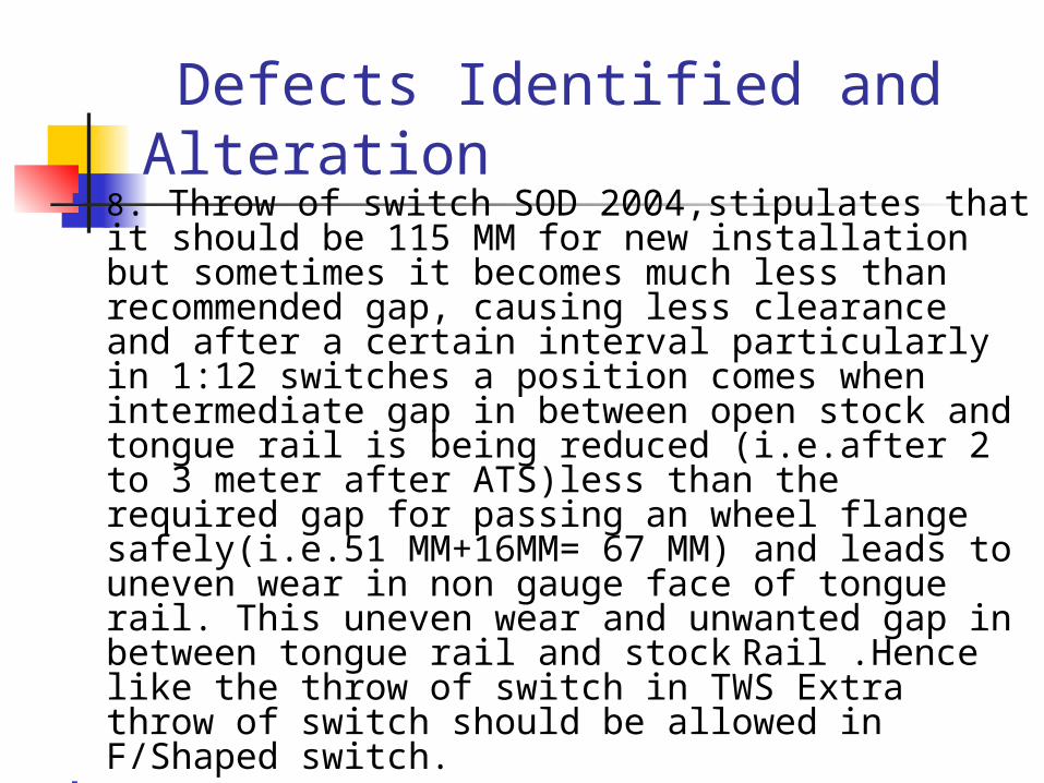
8. Throw of switch SOD 2004,stipulates that it should be 115 MM for new installation but sometimes it becomes much less than recommended gap, causing less clearance and after a certain interval particularly in 1:12 switches a position comes when intermediate gap in between open stock and tongue rail is being reduced (i.e.after 2 to 3 meter after ATS)less than the required gap for passing an wheel flange safely(i.e.51 MM+16MM= 67 MM) and leads to uneven wear in non gauge face of tongue rail. This uneven wear and unwanted gap in between tongue rail and stock Rail .Hence like the throw of switch in TWS Extra throw of switch should be allowed in F/Shaped switch.

Problems and suggestion In Crossing portion 9. GRSP under crossing portion is always
shifted and tends/ comes out of rail seat and dropped . Which causes a greater impact on sleeper seat and get damaged which is irreparable and great loss.
To overcome this problems GRSP under crossing should be modified and a slot for Insert to be provided in both depth and width by suitably increasing the dimensions and slotted Pocket for housing the MCI Insert.(shown in Image in Next slide)

CMS CROSSING
Suitable SLOT given for INSERT in GRSP

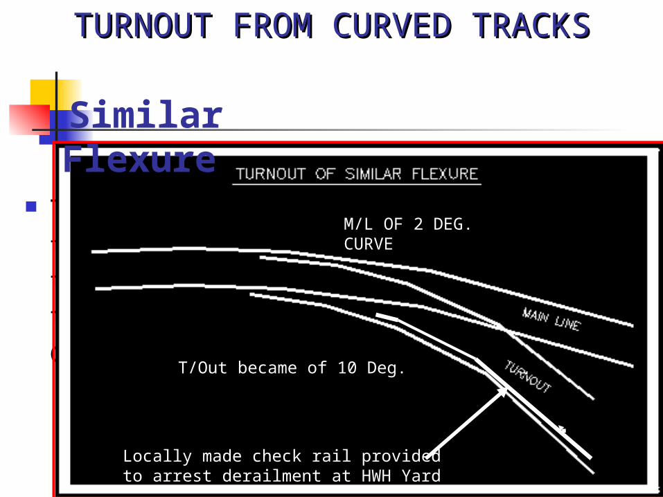
Problems and suggestion In Crossing portion 10.At So many places Non standard 1in 8.5 Turn out is
laid on inside of curves where always derailment takes place on account of design defect. It happens due to Similar flexure Turnout on curved track, Due to this laying defect Degree of resultant curve of turnout increases beyond the prescribed limit (i.e. more than 10 Degree) if the yard curvature exceeds than 2 degree or more.
To overcome this phenomena one Check rail is being provided in such vulnerable lead curves by making non standard arrangement in the interest of safety of track.
Suggestion in fan shaped Layout at such locations special designed structures to be made ,till the work of remodeling of Identified location is carried out.
Turnout takes off towards the same direction
Similar Flexure
TURNOUT FROM CURVED TRACKSTURNOUT FROM CURVED TRACKS
M/L OF 2 DEG. CURVE
T/Out became of 10 Deg.
Locally made check rail provided to arrest derailment at HWH Yard

Problems and suggestion In Crossing portion
At so many locations IN BSP Yard many derailment took place in past and admitted by engineering department honestly on engg account resulting which a proposal for removing all such points is being made and the work of alteration is being carried out by construction department.

Problems and suggestion In Crossing portion
11.In the crossing portion,as soon as wear increases, the impact on sleepers also increases and during long run inner diameter of insert’s hole also increases, resulting work out of ERC from insert.
There are three solutions/practices, implemented by field staff to overcome this problem.
(i) Providing small strips of rubber pads over ERC ,while fitting in insert.
(ii) Locally made tin sheet over ERC (iii) By providing Anti Theft ERC with
Circlip Drg. No.RT-6254 & RT 6255.

USE OF Circlip with Anti theft ERC for Elongated INSERT
http://www.iricen.gov.in/modules.php?name=Forums&file=viewtopic&t=1081
Problems and suggestion In Crossing portion
12. Gapless Joint- Though it is suggested to provide gapless joint in back leg and fore leg of CMS crossing to avoid impact, chipping & variation of cross level .However it is difficult to maintain ,even after, making with a lot of care . Though this issue has already been raised in 76 th TSC but no instruction has yet been issued.
To overcome this problem, it is suggested to use weldable CMS crossing in all main line points and crossing. Though as per railway board’s existing guidelines, 1/7th No. of total population is to be converted annually which will prove as a fruitful measure .

Problems and suggestion In Crossing portion
13. Wear :-There is no fixed criteria for fixing the existing life of CMS Crossing, on account of wear or with passage of time, in present scenario.
In the circular, issued by Finance department describes life of CMS crossing in ”Codal life of assets” as 2 to 4 years, for A class routes but it is not being used for replacement of crossing.
It is required to frame a GMT based criteria for deciding the Life of CMS crossing and Nos of reconditioning which can be done in existing CMS crossing.

Problems and suggestion In Crossing portion It should be fixed Like mentioned for
weldable CMS crossing separately . (A) Guaranteed Service Life -220 GMT
after laying (without reconditioning). (B) Life after reconditioning . Four Nos of reconditioning after
passage of 15 GMT which should be done by manufacturer (i.e. 280 GMT condemning service life) .
Problems and suggestion In Crossing portion
14.Work Hardening :-Just after Laying of CMS crossing , Work hardening of nose is to be done by imposing suitable speed restriction (50 Kmph for specified period) But even also after imposing speed restriction,desired hardening cannot be achieved.
CMS crossing should be supplied with hardening work in workshop itself (i.e .by blasting limited plastic explosives near nose and wing).
Problems and suggestion In Crossing portion
15.Gaplessjoint:-During Laying of ordinary CMS crossing for achieving gapless position , by in situ cutting and drilling holes in rail is not possible and if it is achieved, during contraction of rails a wider gap is formed later.
To achieve the gap less Joint, a strategy is required in which supplier should be asked for fabricating the Approach rails by fabricating it with gapless requirement in workshop( As being done in case of supply of Diamond crossing)

Problems detected in Diamonds crossing When one track crosses another at
an angle Comprising of two acute and two
obtuse crossings.
PSC Layout Diamond crossing
Spl Bearing plate Design laid on sleeper No 7,8 &9 is not suited for modern signaling system ,so at the site it requires cutting with modification by welding channels and providing insulation.
Issue was perhaps raised in TSC also but still no instruction/solution has yet been awaited/obtained.

Local INSULATION provided on B/Plate of Sl No 7,8 &9
Sleeper No 7
Sleeper NO 8Sleeper No 9
First Stretcher Bar at Double slip diamond In Double slip leading stretcher bar there is
no space for fitting the same ,so difference practice is being adapted varying from place to place like.
(i) In BSP yard, leading stretcher bar is removed, setting of Tongue rail is being done by D Bracket of Signal Department and first following stretcher bar
(ii) IN HWH Yard Leading stretcher bar is being provided at 490 mm and 580 mm behind ATS.
So proper drawing suited to site condition after consultation of Track Directorate with Signal Directorate may be issued.
Conclusion It is not possible to mention all the
consequential defects and solution which are not adequately covered in Manuals and existing guidelines. However an honest effort has been made by the participants to highlights some practical problems/defect experienced during course of working.
Thus it is concluded to have a proper research and development by installing representative/intelligent turnout at some problematic location for proper documentation.
Biblography 1. Lecture of Professor Track Machine 2.IRPWM Para no 237 ,317 &1413 3. IRICEN Website & Discussion Forum 4. Points & Crossing ,Design Layout &
Maintenance By Sri Sudhir Kumar 5. www.indianrailway.gov.in 6. Note taken during Foot to Foot
survey Conducted in Pune Yard