Embed Size (px)
Citation preview

www.kentusa.com
M a i n t e n a n c e M a n u a l
K E B S e r i e s E D M
EBN Series EDM Maintenance Manual
- 2 -
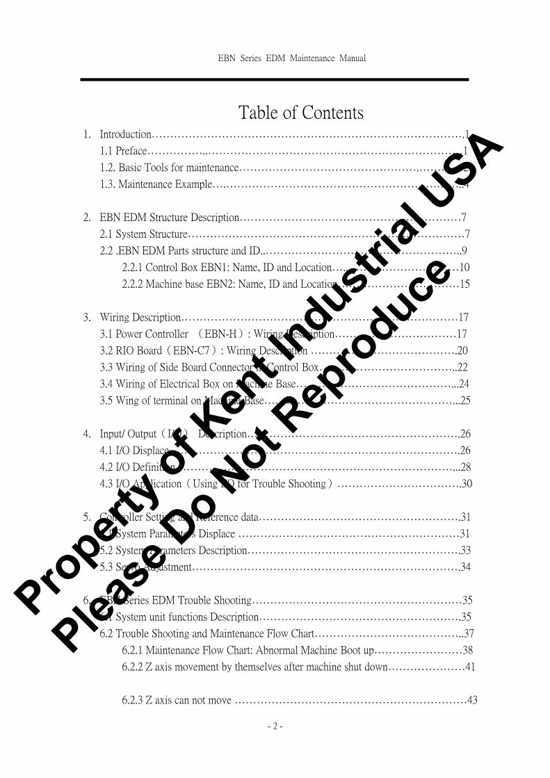
Table of Contents
1. Introduction………………………………………………………………………….1
1.1 Preface……………..……………………………………………………………1
1.2. Basic Tools for maintenance………………………………………….…………2
1.3. Maintenance Example….………………………………………………………..4
2. EBN EDM Structure Description……………………………………………………7
2.1 System Structure…………………………………………………………………7
2.2 .EBN EDM Parts structure and ID..…………………….………………………..9
2.2.1 Control Box EBN1: Name, ID and Location…..…………………………10
2.2.2 Machine base EBN2: Name, ID and Location……………………………15
3. Wiring Description…………………………………………………………………17
3.1 Power Controller (EBN-H): Wiring Description……………………………17
3.2 RIO Board(EBN-C7): Wiring Description ………………………………….20
3.3 Wiring of Side Board Connector in Control Box………………………………..22
3.4 Wiring of Electrical Box on Machine Base……………………………………...24
3.5 Wing of terminal on Machine Base……………………………………………...25
4. Input/ Output(I/O) Description………………………………………………….26
4.1 I/O Displace…………………………………………………………………….26
4.2 I/O Definition…………………………………………………………………...28
4.3 I/O Application(Using I/O for Trouble Shooting)…………………………….30
5. Controller Setting and Reference data……………………………………………….31
5.1 System Parameters Displace ……………………………………………………31
5.2 System Parameters Description………………………………………………….33
5.3 Servo Adjustment……………………………………………………………….34
6. EBN Series EDM Trouble Shooting…………………………………………………35
6.1 System unit functions Description……………………………………………….35
6.2 Trouble Shooting and Maintenance Flow Chart…………………………………..37
6.2.1 Maintenance Flow Chart: Abnormal Machine Boot up……………………38
6.2.2 Z axis movement by themselves after machine shut down…………………41
6.2.3 Z axis can not move ………………………………………………………43
Propert
y of K
ent In
dustrial
USA
Please
Do N
ot Rep
roduce

EBN Series EDM Maintenance Manual
- 3 -
6.2.4 W axis can not move………………………………………………………44
6.2.5 Front Panel and Remote control box malfunction ………………………….45
6.2.6 Pump can not turn on………………………………………………………48
6.2.7 Spark System malfunction…………………………………………………50
6.2.8 Polarity reverse switch malfunction………………………………………..55
6.2.9 Z axes won’t stop while electrode touches workpiece.……………………..56
6.2.10 Synchronize flush malfunction……………………………………………57
6.2.11 Oil Level Switch Malfunction…………………………………………….58
6.2.12 Work light is not ON……………………………………………………..59
6.2.13 Buzzer is not ON…………………………………………………………60
6.2.14 Fire Alarm is not function…………………………………………………61
Append+
(1)EBN-A【A Box】Wiring Diagram
(2)EBN-B【B Box】Wiring Diagram
(3)EBN-C1【C Box】Wiring Diagram
(4)EBN-C2【RIO Board】Wiring Diagram
(5)EBN-C3【RIO Board】Wiring Diagram
(6)CE Wiring Diagram
(7)EBN-D【D Box】Wiring Diagram
(8)EBN-E【E Box】Wiring Diagram
(9)EBN-F【F Box】Wiring Diagram
(10)EBN-G【G Box】Wiring Diagram
(11)EBN-H-1【H Box】Wiring Diagram
(12)EBN-H-2【I Box】Wiring Diagram
(13)EBN-I【I Box】Wiring Diagram
(14)EBN-J【J Box】Wiring Diagram
(15)EBN-K【K Box】Wiring Diagram
(16)EBN2- Electrical Box-1Wiring Diagram
(17)EBN2- Electrical Box-2Wiring Diagram
(18)Machine Base Wiring Diagram
Propert
y of K
ent In
dustrial
USA
Please
Do N
ot Rep
roduce

EBN Series EDM Maintenance Manual
- 4 -
1 Introduction
1.1 Preface JS EDM is a PC-BASED EBN EDM Machine. The EDM System
Structure combine with:
1. PC-BASED Controller developed by JS manufacture.
2. Spark power supply hardware developed by JS manufacture.
3. Servo System and Machine Base.
EBN-606 EDM maintenance manual includes:
(1)System structure definition and description.
(2)System structure function and description.
(3)System structure error messages and trouble shooting.
Basic knowledge needed:
(1)Familiar with EDM operation.
(2)Knowledge of basic Electronic and Computer 。
(3)Basic Knowledge of mechanical Structure.
(4)Knowledge of using Multi Meter
1.2 Maintenance Note Symbol used:
Symbol Description
~ Warning Might cause damage to technician if not proper use
! Note Might damage the machine if not correct wiring or incorrect
installation.
! Hint Provide the information for service
! Note
**Please back up one copy of system parameter.
*If there is any system parameters need to be changed,
please back up one copy of the original system
parameter for future used.
Propert
y of K
ent In
dustrial
USA
Please
Do N
ot Rep
roduce

EBN Series EDM Maintenance Manual
- 5 -
~ Warning
! Hint
1.2 Tools for Malignance
(1)Multi Meter:Multi Meter is used so often while Maintains.
Digital Multi meter is suggested.
Minimum Requirement:
�Can Check ACV 0~750V
�Can Check DCV 0~250V
�Can CheckΩ 0~1MΩ
1. Usually the machine is power on when technician is trouble
shooting. Might cause electrical shot if not work carefully.
2. Do not touch the EDM when the machine is cutting. For the
high voltage might cause electrical shot.
3. Do not put your hand in the mechanical structure while table
is moving.
*parameters:
Please set up the proper parameter。
Wrong parameter might cause the machine operate not
properly 。Machine parameters are very important setting for
correct operation.
*back up:
Parameter back up is important and necessary
Propert
y of K
ent In
dustrial
USA
Please
Do N
ot Rep
roduce

EBN Series EDM Maintenance Manual
- 6 -
(2) Screw Driver:Needed when Connect or disconnect wire
terminals
(3)Soldering Gun and Solder: Needed when replace electronic
elements.
(4)Allen Key and Adjustable Wrench: Needed when assemble
machine parts.
Propert
y of K
ent In
dustrial
USA
Please
Do N
ot Rep
roduce

EBN Series EDM Maintenance Manual
- 7 -
(5)Diagonal cutter & long nose pliers
1.3 Maintenance Example When machine is malfunction, please follow the Maintenance
manual for trouble shooting.
Example:“Working light is not ON”Function Failure
You can find “Working light is not ON ” Trouble shooting in Chapter 6.12,
EBN-H12
LAMP
EBN-H1F4
7A/30mm
35
1
EBN-D3
1AC0VV/2A
AC1 +
-AC2
BD1KBPC2506/25A
EBN2-M7EBN-I2
2
EBN-H11
2
32
EBN2-M40CN2
AC12V/2A
Reference Circuit
Propert
y of K
ent In
dustrial
USA
Please
Do N
ot Rep
roduce

EBN Series EDM Maintenance Manual
- 8 -
(1)Components symbol description:
EBN-I2.1 EBN-H1.32
EBN2-M40CN2 EBN2-M7
Maintenance flow chart
Power
supply Power
supply
I2 Connector #1 Leg Control Panel
H1Terminal
#32 point
Small
Power
supply
CN2
Connector
Machine
base
quartz lamp
Chek fuses of EBN-H12
(F4/7A)is ok? Replace fuses(EBN-H12)。
(Yes)
(No)
Is there AC12V output from
AC12V/2A of EBN-D3 on
small transformer ?
(Yes)
(No) Replace small
transformer(EBN-D3)。
Check the out of of quartz lamp on
small power generator. Is there
AC12V output from
EBN2-M40CN2?
(No)
(Yes)
Is there bad contactor on
circuit?
Is EBN2-M7 quartz lamp
burn out?
(Yes)
Replace quartz lamp.
(EBN2-M7)
之燈泡 。
Propert
y of K
ent In
dustrial
USA
Please
Do N
ot Rep
roduce

EBN Series EDM Maintenance Manual
- 9 -
(2)Appendant Drawing is the schematic of EBN-600 EDM:
○1 EBN-A.DSN--A Box schematic,includes the wiring of monitor.
○2 EBN-B.DSN--B Box schematic,includes the wiring of servo driver.
○3 EBN-C1.DSN--C Box schematic,includes the wiring of controller.
○4 EBN-C2.DSN--C Box schematic,includes the wiring of I/O
interface.
○5 EBN-D.DSN--D Box schematic,includes the wiring of big and
small transformers.
○6 EBN-E.DSN--E Box schematic,includes the wiring of all switches
and press keys on Front panel.
○7 EBN-F.DSN--F Box schematic,includes the wiring of Current Limit
frame.
○8 EBN-G.DSN--G Box schematic,includes the wiring of transistors
box.
○9 EBN-H1.DSN--H Box schematic,includes the wiring of Controller
circuit.
○10 EBN-H2.DSN--H Box schematic,includes the wiring of Spark
Control circuit.
○11 EBN-I.DSN--I Box schematic,includes the wiring of Side Board
connectors.
○12 EBN2.DSN--Small electrical Box schematic , includes the wiring of
terminals and connectors on small electrical box.
○13 Machine Base Wiring. DSN--Schematic of machine base,includes
the wiring of all components.
Propert
y of K
ent In
dustrial
USA
Please
Do N
ot Rep
roduce

EBN Series EDM Maintenance Manual
- 10 -
2 EBN EDM Structure Description
2.1 System structure JS EBN EDM machine power generator used PC-BASED controller. The spark system is
developed by JS R&D department。 The system specification is described as follow:
(I)Controller:Industrial PC, Intel DX4-100 CUP is used for:
○1 I/O interface Data process.
○2 NC program compile.
○3 Motion control
○4 Spark control
○5 motion control card. (X,Y axis control: optional)
○6 One PULSE & GAP Board。
(II)Servo:One DC SERVO DRIVER is used。
(III)Spark POWER:There are 3 different specifications: 60A、120A、180A
� 60A→One high voltage board, one low voltage board。
� 120A→One high voltage board, two low voltage board。
� 180A→One high voltage board, 3 low voltage board。
EBN EDM control system structure is shown as Fig. 2.1:
POWER
RACKCONTROLER
RIO
Hard KEY
MMITEXTKEY
IPC
Motion
Pulse&
GapL.V-180A
H.V&SINK
L.V-60A
L.V-120A
I/O
MOTORDriver
學光 尺
Fig 2.1 EBN EDM System Structure
Scale
SCALE
Propert
y of K
ent In
dustrial
USA
Please
Do N
ot Rep
roduce

EBN Series EDM Maintenance Manual
- 11 -
EBN EDM Spark power structure is shown as Fig. 2.2.
HV_PULSE GAP LV_PUSE
L.V H.V
Fig. 2.2 EBN-600 Series. Schematic of Basic
Spark Circuit Loop.
Propert
y of K
ent In
dustrial
USA
Please
Do N
ot Rep
roduce
EBN Series EDM Maintenance Manual
- 12 -
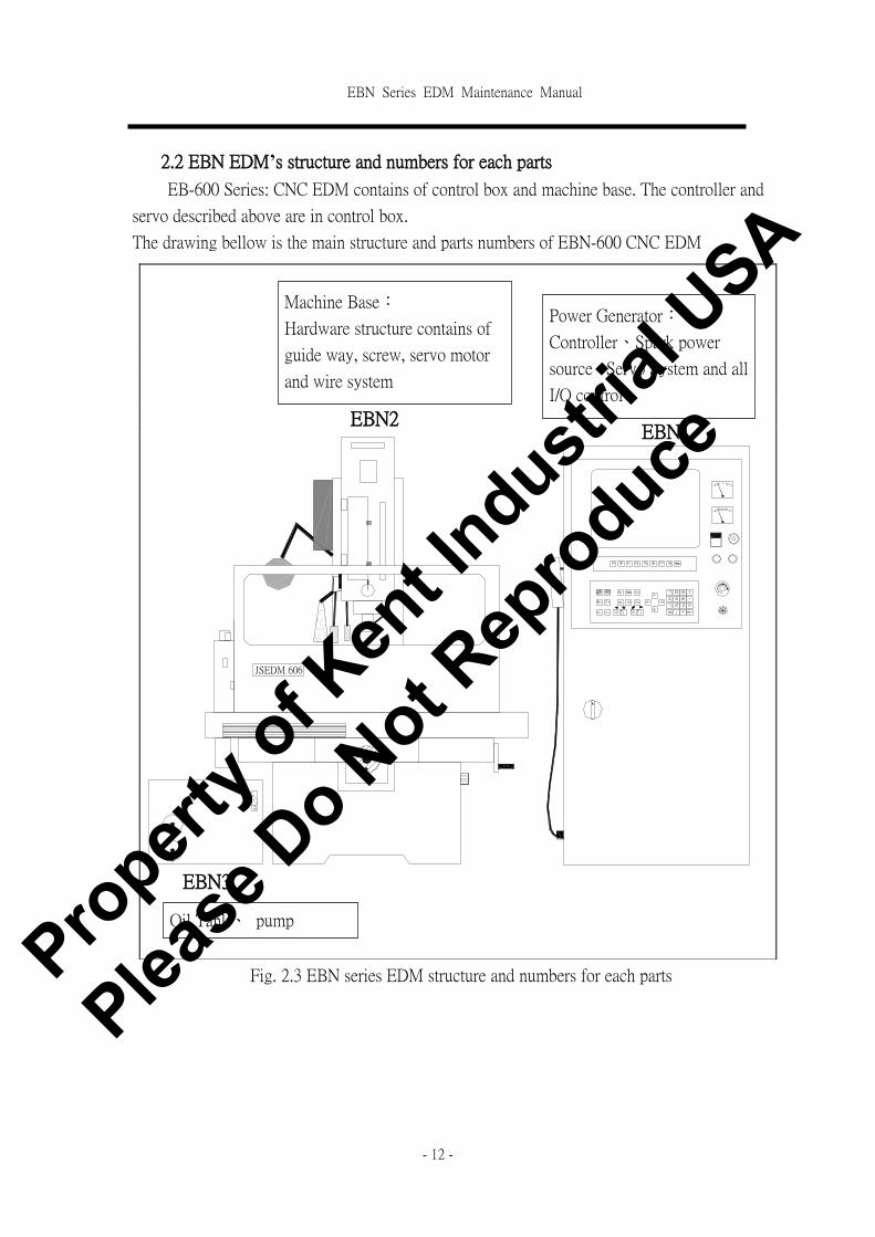
2.2 EBN EDM’s structure and numbers for each parts
EB-600 Series: CNC EDM contains of control box and machine base. The controller and
servo described above are in control box.
The drawing bellow is the main structure and parts numbers of EBN-600 CNC EDM
Fig. 2.3 EBN series EDM structure and numbers for each parts
JSEDM 606
EBN2 EBN1
EBN3
Machine Base:
Hardware structure contains of
guide way, screw, servo motor
and wire system
Power Generator:
Controller、Spark power
source、Servo System and all
I/O control
Oil Tank、 pump
Propert
y of K
ent In
dustrial
USA
Please
Do N
ot Rep
roduce

EBN Series EDM Maintenance Manual
- 13 -
2.2.1 Control box EBN1’s structure and numbers for each parts
In spite of Control System and Spark System,Power Generator includes Power supply System
and electrical panel . The structure is shown as follow:
圖 2.3 EBN Front view of control box.
A box
B box
C box
D box
I box
B1 B2
C1 C2
C3
C7
C4
D1
D3
D2
E box
A1
C6
E5
E7
E6
E1
E2
V
A E3
E4
E8
E10
E9
E11
Front Door
J1
C5
Propert
y of K
ent In
dustrial
USA
Please
Do N
ot Rep
roduce
EBN Series EDM Maintenance Manual
- 14 -
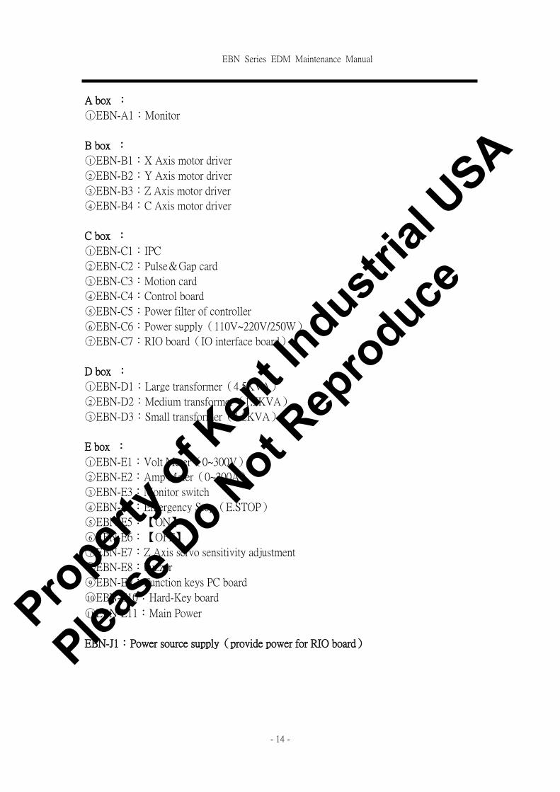
A box :
○1 EBN-A1:Monitor
B box :
○1 EBN-B1:X Axis motor driver
○2 EBN-B2:Y Axis motor driver
○3 EBN-B3:Z Axis motor driver
○4 EBN-B4:C Axis motor driver
C box :
○1 EBN-C1:IPC
○2 EBN-C2:Pulse&Gap card
○3 EBN-C3:Motion card
○4 EBN-C4:Control board
○5 EBN-C5:Power filter of controller
○6 EBN-C6:Power supply(110V~220V/250W)
○7 EBN-C7:RIO board(IO interface board)
D box :
○1 EBN-D1:Large transformer(4.5KVA)
○2 EBN-D2:Medium transformer(1.5KVA)
○3 EBN-D3:Small transformer(1.2KVA)
E box :
○1 EBN-E1:Volt Meter(0~300V)
○2 EBN-E2:Amp Meter(0~200A)
○3 EBN-E3:Monitor switch
○4 EBN-E4:Emergency Stop(E.STOP)
○5 EBN-E5:【ON】
○6 EBN-E6:【OFF】
○7 EBN-E7:Z Axis servo sensitivity adjustment
○8 EBN-E8:buzzer
○9 EBN-E9:Function keys PC board
○10EBN-E10:Hard-Key board
○11EBN-E11:Main Power
EBN-J1:Power source supply(provide power for RIO board)
Propert
y of K
ent In
dustrial
USA
Please
Do N
ot Rep
roduce
EBN Series EDM Maintenance Manual
- 15 -
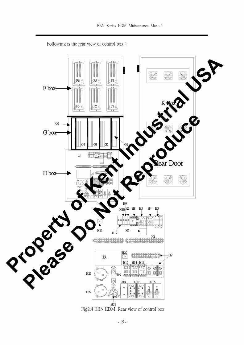
Following is the rear view of control box:
F box
G box
H box
K Box
Rear Door
F1
G1
F6
F3 F2
F5 F4
G5
G4 G3 G2
H1
H2
H7
H6
H5 H4 H3 H8
H9
H10
H11 H12
J2 H15 H14 H13
H16 H18 H17
H19
H21
H20
H22
H23
Fig2.4 EBN EDM. Rear view of control box.
Propert
y of K
ent In
dustrial
USA
Please
Do N
ot Rep
roduce

EBN Series EDM Maintenance Manual
- 16 -
F box :
○1 EBN-F1:Hi voltage current limit resistor.
○2 EBN-F2:Low voltage current limit resistor-1(30A)
○3 EBN-F3:Low voltage current limit resistor -2(60A)
○4 EBN-F4:Low voltage current limit resistor -3(90A)
○5 EBN-F5:Low voltage current limit resistor -4(120A)
○6 EBN-F6:Low voltage current limit resistor -5(180A)
G box :
○1 EBN-G1:Hi voltage board
○2 EBN-G2:Low voltage board -1(60A)
○3 EBN-G3:Low voltage board -2(120A)
○4 EBN-G4:Low voltage board -3(180A)
○5 EBN-G5:G box board(transistor box board)
H box :
○1 EBN-H1:terminal-1(36 point)
○2 EBN-H2:terminal-2(20 point)
○3 EBN-H3:Fuse-3P/25A( Main Power)
○4 EBN-H4:Relay(Control Main Power)
○5 EBN-H5:Relay(Control Pump)
○6 EBN-H6:Overload Relay(Control Pump)
○7 EBN-H7:Fuse-7A(Power of controller)
○8 EBN-H8:Relay(Power of controller)
○9 EBN-H9:Fuse-3A(power of Hi/Low power supply)
○10EBN-H10:Fuse-3A(power of fans)
○11EBN-H11:Rectifier
○12EBN-H12:Fuse-2A(Power of quartz lamp)
○13EBN-H13:Relay(polarity switch control)
○14EBN-H14:Relay(Spark Control)
○15EBN-H15:Relay(Spark control. For 90A and above)
○16EBN-H16:Diode
○17EBN-H17:3 phase rectifier(Low voltage spark rectifier)
○18EBN-H18:3 phase rectifier(Hi voltage spark rectifier)
○19EBN-H19:Distributor
○20EBN-H20:Rectifier(2nd Hi Voltage spark rectifier)
○21EBN-H21:Capacitor(HiV Spark Filter)
○22EBN-H22:Capacitor(LowV Spark Filter)
○23EBN-H23:Capacitor(LowV Spark Filter. For 90A and above)
EBN-J2:Power Supply(Provide power for High and Low voltage board)
Propert
y of K
ent In
dustrial
USA
Please
Do N
ot Rep
roduce
EBN Series EDM Maintenance Manual
- 17 -
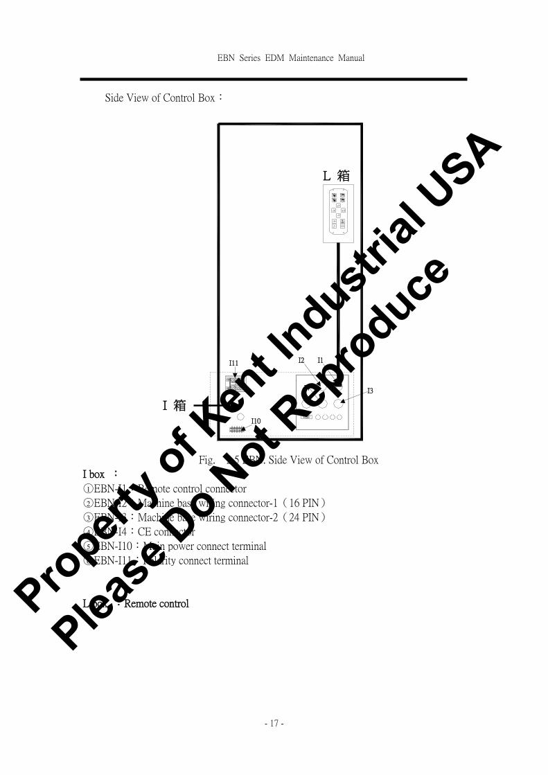
Side View of Control Box:
Fig. 2.5 EBN. Side View of Control Box
I box :
○1 EBN-I1:Remote control connector
○2 EBN-I2:Machine base wiring connector-1(16 PIN)
○3 EBN-I3:Machine base wiring connector-2(24 PIN)
○4 EBN-I4:CE connector
○5 EBN-I10:Main power connect terminal
○6 EBN-I11:Polarity connect terminal
L box :Remote control
I 箱
I2 I1
I4 I3
I10
I11
L 箱
Propert
y of K
ent In
dustrial
USA
Please
Do N
ot Rep
roduce

EBN Series EDM Maintenance Manual
- 18 -
2.2.2 Machine Base EBN2’s structure and numbers for each parts
Following picture is Machine Base Structure for CNC EDM,This Machine Base has 3 DC
servo Motor ,Control the motions of X、Y、Z axis
Machine Base: Components locations, numbers and definition:(Machine Base symbol:
M)。
Front view of Machine base:
EBN2:Machine base(M box )-Front View ○1 EBN2-M1A:terminal-1 ○11 EBN2-M24:synchronize flush
○2 EBN2-M3:Z axis DC servo motor ○12 EBN2-M25:Level Switch
○3 EBN2-M5A:Z axis hardware + limit Switch ○13 EBN2-M35:Oil Tank Door Limit Switch(CE Specific)
○4 EBN2-M5B:Z axis software + limit Switch
○5 EBN2-M6:Z axis hardware - limit Switch
○6 EBN2-M7:Quartz light
○7 EBN2-M8:Z axis DRO
○8 EBN2-M11:Fire sensor
○9 EBN2-M14:X axis DRO
○10EBN2-M18:Y axis DRO
JSEDM 606
M1
M5A,M5B
M3
M8M6
M7
M11M24
M25M14 M13A
M18
M35
Propert
y of K
ent In
dustrial
USA
Please
Do N
ot Rep
roduce

EBN Series EDM Maintenance Manual
- 19 -
Machine Rear View:
EBN2:Machine base(M box )- Rear view
�EBN2-M20:W axis AC motor ○8 EBN2-M40:Small Control box
�EBN2-M22:W axis limit switch-up CN1:AC110 connector
�EBN2-M23:W axis limit switch-down CN2:Quartz lamp connector
�EBN2-M26:Inlet of Pump CN3:Synchronize flush and level switch connectors
�EBN2-M33:CE Emergency Stop CN4:Pump connector
○7 EBN2-M34:CE Temp. Control switch TB1~TB4:terminal
CN4
CN3
CN2
CN1TB1
M26
M33
M34
M40
M22M23
M20
I11 I3 I2
Propert
y of K
ent In
dustrial
USA
Please
Do N
ot Rep
roduce
EBN Series EDM Maintenance Manual
- 20 -
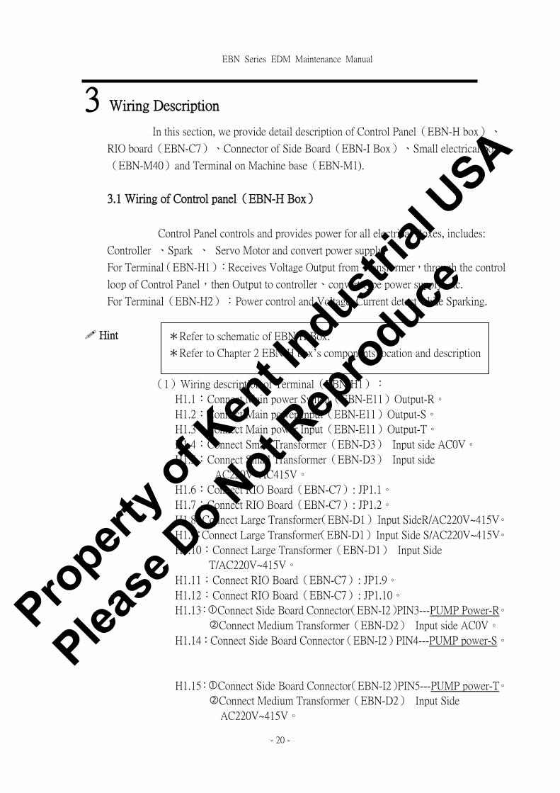
3 Wiring Description
In this section, we provide detail description of Control Panel(EBN-H box)、
RIO board(EBN-C7)、Connector of Side Board(EBN-I Box)、Small electrical box
(EBN-M40)and Terminal on Machine base(EBN-M1).
3.1 Wiring of Control panel(EBN-H Box)
Control Panel controls and provides power for all electrical Boxes, includes:
Controller 、Spark 、 Servo Motor and convert power supply.
For Terminal(EBN-H1):Receives Voltage Output from Transformer,through the control
loop of Control Panel,then Output to controller、convert type power supply, etc.
For Terminal(EBN-H2):Power control and Voltage, Current detect while Sparking.
! Hint
(1)Wiring description of Terminal(EBN-H1):
H1.1:Connect Main power Switch(EBN-E11)Output-R。
H1.2:Connect Main power Input(EBN-E11)Output-S。
H1.3:Connect Main power Input(EBN-E11)Output-T。
H1.4:Connect Small Transformer(EBN-D3) Input side AC0V。
H1.5:Connect Small Transformer(EBN-D3) Input side
AC220V~AC415V。
H1.6:Connect RIO Board(EBN-C7): JP1.1。
H1.7:Connect RIO Board(EBN-C7): JP1.2。
H1.8:Connect Large Transformer(EBN-D1) Input SideR/AC220V~415V。
H1.9:Connect Large Transformer(EBN-D1) Input Side S/AC220V~415V。
H1.10:Connect Large Transformer(EBN-D1) Input Side
T/AC220V~415V。
H1.11:Connect RIO Board(EBN-C7): JP1.9。
H1.12:Connect RIO Board(EBN-C7): JP1.10。
H1.13:�Connect Side Board Connector(EBN-I2)PIN3---PUMP Power-R。
�Connect Medium Transformer(EBN-D2) Input side AC0V。
H1.14:Connect Side Board Connector(EBN-I2)PIN4---PUMP power-S。
H1.15:�Connect Side Board Connector(EBN-I2)PIN5---PUMP power-T。
�Connect Medium Transformer(EBN-D2) Input Side
AC220V~415V。
*Refer to schematic of EBN-H Box.
*Refer to Chapter 2 EBN-H box’s components location and description
Propert
y of K
ent In
dustrial
USA
Please
Do N
ot Rep
roduce

EBN Series EDM Maintenance Manual
- 21 -
H1.16:Connect Small Transformer(EBN-D3)Output Side AC110V/6A
(0V)。
H1.17:Connect Small Transformer(EBN-D3)Output side AC110V/6A
(110V)。
H1.18:Connect Small Transformer(EBN-D3)Output Side AC110V/2A
(0V)。
H1.19:Connect Small Transformer(EBN-D3)Output Side AC110V/2A
(110V)。
H1.20:Connect RIO Board(EBN-C7): JP1.19。
H1.21:Connect RIO Board(EBN-C7): JP1.20。
H1.22:Connect Panel ON Key(EBN-E5)Connect point# 3。
H1.23:Connect Panel ON Key(EBN-E5)Connect point #4。
H1.24:Connect Medium Transformer(EBN-D2)Output side AC220V/1.5A
(0V)
H1.25:Connect Medium Transformer(EBN-D2)Output side AC220V/1.5A
(220V)
H1.26:�Connect Controller Power Filter(EBN-C5): LINE-1。
�Connect RIO Board Convert type power supply(EBN-J1):
InputAC-1。
�Connect Side BoardEBN-I2.7,AC0V。
H1.27:�Connect Controller Power Filter(EBN-C5): LINE-2。
�Connect RIO Board Convert type power supply(EBN-J1):
InputAC-2。
H1.28:Connect L.V&H.V Board Convert type power supply(EBN-J2):
InputAC-1。
H1.29:Connect L.V&H.V board Convert type power supply(EBN-J2):
InputAC-2。
H1.30:Connect power of Fan(EBN-K box) InputAC-1。
H1.31:Connect power of Fan(EBN-K Box) InputAC-2。
H1.32:Connect Side Board Connector(EBN-I2)PIN1---Quartz Light 0V。
H1.33:Connect RIO Board(EBN-C7): JP5.9。
H1.34:Connect RIO Board(EBN-C7): JP5.10。
H1.35:Connect Small Transformer(EBN-D3)Output Side AC12V/1.5A
(0V)。
(2)Wiring description of terminal(EBN-H2):
H2.41:Connect RIO Board(EBN-C7): JP1.5。
H2.42:Connect RIO Board(EBN-C7): JP1.6。
H2.43:Connect RIO Board(EBN-C7): JP1.7。
H2.44:Connect RIO Board(EBN-C7): JP1.8。
Propert
y of K
ent In
dustrial
USA
Please
Do N
ot Rep
roduce

EBN Series EDM Maintenance Manual
- 22 -
H2.45:Connect RIO Board(EBN-C7): JP1.1。
H2.46:Connect RIO Board(EBN-C7): JP1.2。
H2.47:�Connect Volt meter(EBN-E1):+ End
�Connect MOTION card(EBN-C2): JP2.2。
H2.48:�Connect Volt meter(EBN-E1)的-End
�Connect MOTION card(EBN-C2): JP2.3。
H2.49:Connect Amp meter(EBN-E2)的+End
H2.50:Connect Amp meter(EBN-E2)的-End
H2.51:Connect Transistor Board(EBN-G5): S24 point
H2.52:Connect Transistor Board(EBN-G5): S10 point
H2.53:Connect Transistor Board(EBN-G5): S1 point。
H2.54:Connect Transistor Board(EBN-G5): S2 point。
H2.55:Connect HV Current Limit frame(EBN-F1): S1 point。
H2.56:Connect Transistor Board(EBN-G5): S6 point。
H2.57:Connect Transistor Board(EBN-G5): S7 point。
H2.58:Connect LV Current Limit frame(EBN-F2): S1 point。
Propert
y of K
ent In
dustrial
USA
Please
Do N
ot Rep
roduce

EBN Series EDM Maintenance Manual
- 23 -
3.2 Wiring of RIO Board(EBN-C7)
RIO Board provides the Output and Input function for EBN Series EDM machine. In
spite of the Input/Output signal of operation Panel,all other Input and Output signals are
process by RIO Board,such as Limit Switch、Polarity switch、Fire Alarm Signal 、 Short
circuit Signal and etc.
Output/Input Signals of RIO Board are connected to the socket(JP1~JP12).
JP1.7 means Pin7 point on socket JP1.
! Hint
(1)Wiring description of socket JP1:
JP1.1:Connect Control Panel EBN-H1.6,Power On Signal 。
JP1.2:Connect Control Panel EBN-H1.7,Power On Signal 。
JP1.3:Connect coil of relay (only CE)。
JP1.4:Connect coil of relay (only CE)。
JP1.5:Connect Control Panel EBN-H1.41, Spark ON Signal 。
JP1.6:Connect Control Panel EBN-H1.42, Spark ON Signal 。
JP1.7:Connect Control Panel EBN-H1.43,Polarity switch Signal 。
JP1.8:Connect Control Panel EBN-H1.44,Polarity switch Signal 。
JP1.9:Connect Control Panel EBN-H1.11,PUMP On Signal 。
JP1.10:Connect Control Panel EBN-H1.12,PUMP On Signal 。
JP1.11:Fast oil PUMP On Signal(Only 707~909)。
JP1.12:Fast oil PUMP On Signal(Only 707~909)。
JP1.13:Connect Side BoardEBN-I2.9,W axis UP Signal 。
JP1.14:Connect Side BoardEBN-I2.8,W axis common point。
JP1.15:Connect Side BoardEBN-I2.10,W axis Down Signal 。
JP1.16:Open Loop。
JP1.17:Open Loop。
JP1.18:Open Loop。
JP1.19:Connect Control Panel EBN-H1.20,POWER ON Signal 。
JP1.20:Connect Control Panel EBN-H1.21,POWER ON Signal 。
(2)Wiring description of socket JP2:
JP2.1:Connect Control Panel EBN-H2.45, Short circuit Signal +point。
JP2.2:Connect Control Panel EBN-H2.46, Short circuit Signal -point。
*Refer to schematic of EBN-C7
*Refer to Chapter 2 EBN-C Box components location and description
Propert
y of K
ent In
dustrial
USA
Please
Do N
ot Rep
roduce

EBN Series EDM Maintenance Manual
- 24 -
(3)Wiring description of socket JP5:
JP5.1:Connect Oil Tank Door Limit Switch(Only CE Specific)。
JP5.2:Connect Oil Tank Door Limit Switch(Only CE Specific)。
JP5.3:Open Loop。
JP5.4:Connect Side BoardEBN-I2.14, Synchronize Flush Signal 。
JP5.5:Open Loop。
JP5.6:Connect Side BoardEBN-I2.13, Level Switch。
JP5.7:Open Loop。
JP5.8:Connect Side BoardEBN-I2.16,FIRE ALARM。
JP5.9:Connect Control Panel EBN-H1.33,FIRE ENABLE(+)。
JP5.10:Connect Control Panel EBN-H1.34,FIRE ENABLE(-)。
JP5.11:Open Loop。
JP5.12:Connect Side BoardEBN-I2.15,Z axis ○+ Limit Signal 。
JP5.13 &JP5.14:SHORT。
JP5.15: Open Loop。
JP5.16: Open Loop。
(4)Wiring description of socket JP8:
JP8.1:Connect Side BoardEBN-I2.11,DC+24V。
JP8.2:Connect Side BoardEBN-I2.12,GND。
(5)Wiring description of socket JP12:
JP12.1:�point for Connecting E. STOP Switch(EBN-E3)on panel。
JP12.2:�point for Connecting E.STOP Switch(EBN-E3)on panel。
JP12.3:Connect Buzzer (EBN-E8)的+End。
JP12.4:Connect Buzzer (EBN-E8)的-End
JP12.5:�point for Connecting【OFF】 Key(EBN-E6)on panel。
JP12.6:�point for connecting 【OFF】 Key(EBN-E6)on panel。
(6)Wiring description of other sockets:
JP3:Connect Side BoardEBN-I1,Remote Box signal。
JP4:Connect JP3 of MOTION Board。
JP11:Extra I/O point。
Propert
y of K
ent In
dustrial
USA
Please
Do N
ot Rep
roduce

EBN Series EDM Maintenance Manual
- 25 -
3.3 Wiring of Side Board Connector :
Side Board(EBN-I Box)is to connect Small Electrical Box on Machine Base to Control
Box。Through the Side Board can control the motion of machine base, DRO feedback, pump
ON/OFF and I/O Signal of machine base. Side Board Connector is marked as EBN-I.
Example: I2.4 means PIN4 on Connector I2.
I1: connector to remote control box.
I4: Special design for the connector of CE model.
I3 is DRO(X、Y、Z)Connector;
Following is the wiring description of Connector I2 to Small Electrical Box (EBN-M40)
on machine base.
! Hint
(1)Wiring description of I2 Connector:
I2.1:Connect to CN2.1 on Small Electrical Box (EBN2-M40), Quartz
lamp/AC12V。
I2.2:Connect to CN2.2 Small Electrical Box (EBN2-M40), Quartz
lamp/AC0V。
I2.3:Connect to CN4.1 on Small Electrical Box (EBN2-M40),PUMP
Power(R)。
I2.4:Connect to CN4.2 on Small Electrical Box (EBN2-M40),PUMP
Power(S)。
I2.5:Connect to CN4.3 on Small Electrical Box (EBN2-M40),PUMP
Power(T)。
I2.6:Connect to TB1.20 on Small Electrical Box (EBN2-M40),PUMP
Ground
I2.7:Connect to CN1.2 on Small Electrical Box (EBN2-M40),AC110V。
I2.8: ○1 Connect to CN1.1 on Small Electrical Box (EBN2-M40),
AC0V。
○2 Connect to TB1.1 on Small Electrical Box (EBN2-M40),W
axis common point。
I2.9:Connect to TB1.2 on Small Electrical Box (EBN2-M40),W axis
UP Signal 。
I2.10:Connect to TB1.3 on Small Electrical Box (EBN2-M40),W axis
Down Signal 。
I2.11:Connect to CN3.1 on Small Electrical Box (EBN2-M40),DC24V。
*Refer to the schematic of EBN-I Box。
*Refer to Chapter 2 EBN-I box’s components location and description
Propert
y of K
ent In
dustrial
USA
Please
Do N
ot Rep
roduce

EBN Series EDM Maintenance Manual
- 26 -
I2.12:○1 Connect to CN3.2 on Small Electrical Box (EBN2-M40),
DC0V。
○2 Connect to TB1.4 on Small Electrical Box (EBN2-M40),FIRE
ALARM ○+ END。
I2.13:Connect to CN3.3 on Small Electrical Box (EBN2-M40), Level
Switch。
I2.14:Connect to CN3.4 on Small Electrical Box (EBN2-M40),
Synchronize Flush Signal 。
I2.15:Connect to TB1.5 on Small Electrical Box (EBN2-M40),Z axis
○+ Limit Signal 。
I2.16:Connect to TB1.4 on Small Electrical Box (EBN2-M40),FIRE
ALARM ○- END。
(2)Wiring description of I3Connector:
I3.1:Connect to TB1.7 on Small Electrical Box (EBN2-M40),Z axis
Motor Power ○+ End。
I3.2:Connect to TB1.8 on Small Electrical Box (EBN2-M40),Z axis
Motor Power ○- End。
I3.3:Connect to TB1.9 on Small Electrical Box (EBN2-M40),Z axis
TG ○+ End。
I3.4:Connect to TB1.10 on Small Electrical Box (EBN2-M40),Z axis
TG ○- End。
I3.5:Connect to TB1.11 on Small Electrical Box (EBN2-M40),Z axis
Protect common point。
I3.6:Connect to TB1.12 on Small Electrical Box (EBN2-M40),Z axis
○+ Protect Signal。
I3.7:Connect to TB1.13 on Small Electrical Box (EBN2-M40),Z axis
○- Protect Signal。
Propert
y of K
ent In
dustrial
USA
Please
Do N
ot Rep
roduce
EBN Series EDM Maintenance Manual
- 27 -
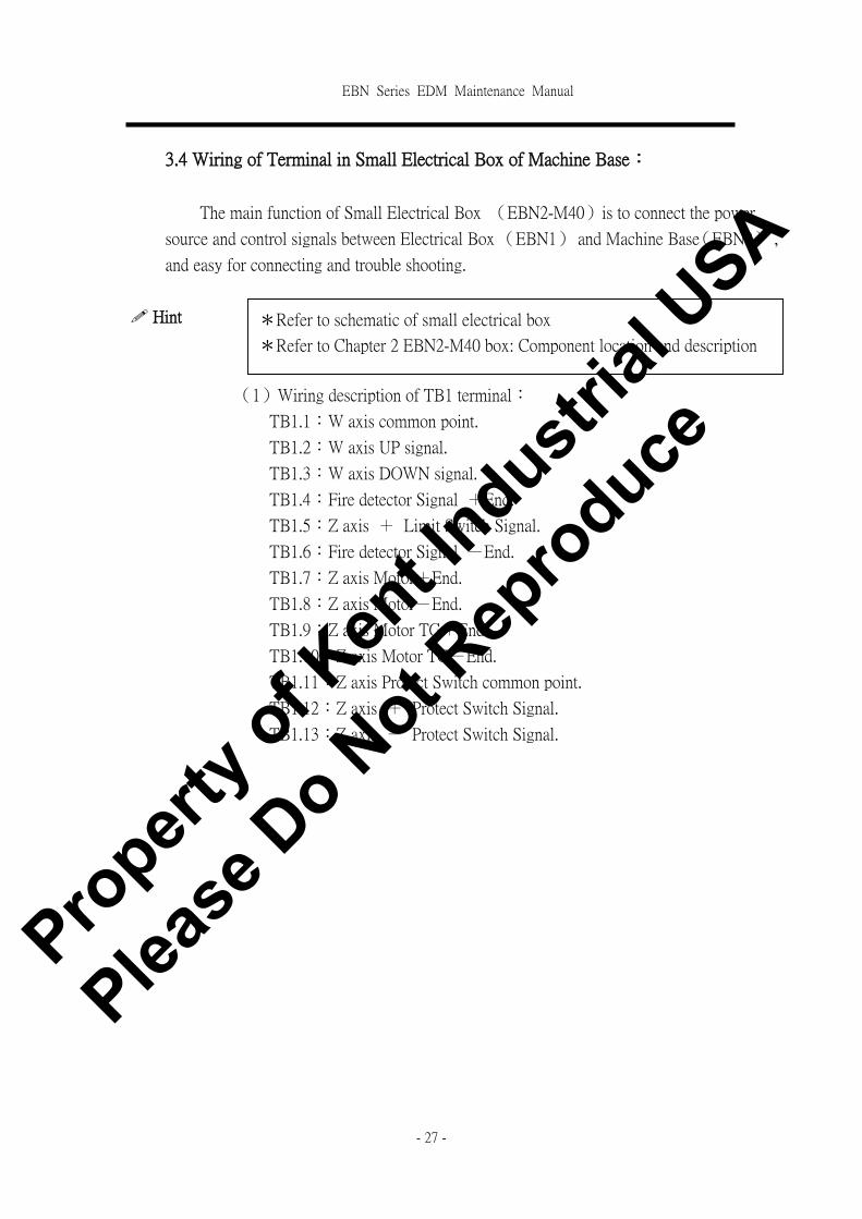
3.4 Wiring of Terminal in Small Electrical Box of Machine Base:
The main function of Small Electrical Box (EBN2-M40)is to connect the power
source and control signals between Electrical Box (EBN1) and Machine Base(EBN2) ,
and easy for connecting and trouble shooting.
! Hint
(1)Wiring description of TB1 terminal:
TB1.1:W axis common point.
TB1.2:W axis UP signal.
TB1.3:W axis DOWN signal.
TB1.4:Fire detector Signal +End.
TB1.5:Z axis + Limit Switch Signal.
TB1.6:Fire detector Signal -End.
TB1.7:Z axis Motor+End.
TB1.8:Z axis Motor-End.
TB1.9:Z axis Motor TG+End.
TB1.10:Z axis Motor TG-End.
TB1.11:Z axis Protect Switch common point.
TB1.12:Z axis + Protect Switch Signal.
TB1.13:Z axis - Protect Switch Signal.
*Refer to schematic of small electrical box
*Refer to Chapter 2 EBN2-M40 box: Component location and description
Propert
y of K
ent In
dustrial
USA
Please
Do N
ot Rep
roduce

EBN Series EDM Maintenance Manual
- 28 -
3.5 Wiring of terminal on Machine Base:
! Hint
The wiring of terminal (EBN2-M1) is described as following:
M1.1:Z axis Motor+End.
M1.2:Z axis Motor-End.
M1.3:Z axis Motor TG+End.
M1.4:Z axis Motor TG-End.
M1.5:Z axis Protect Switch common point.
M1.6:Z axis + Protect Switch Signal.
M1.7:Z axis - Protect Switch Signal.
M1.8:○1 Z axis Limit Switch common point.
○2 Fire Detector Signal -End.
M1.9:Z axis + Limit Switch Signal.
M1.10:Fire Detector Signal +End.
*Refer to the schematic of Machine base Wiring。
*Refer to Chapter 2 EBN2-M Box: Components location and
Description。
Propert
y of K
ent In
dustrial
USA
Please
Do N
ot Rep
roduce

EBN Series EDM Maintenance Manual
- 29 -
4 Input/ Output(I/O) Description
The I/O status will show on the screen for trouble shooting。
4.1 I/O Display
I/O Displace:
(1)Press【ESC】key under Main Screen and Enter to System Screen.
Fig 4.1 System Screen
Propert
y of K
ent In
dustrial
USA
Please
Do N
ot Rep
roduce
EBN Series EDM Maintenance Manual
- 30 -
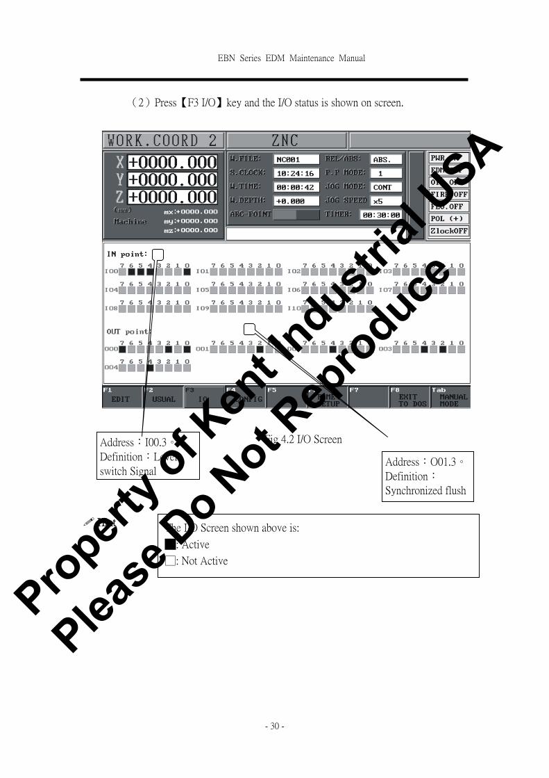
(2)Press【F3 I/O】key and the I/O status is shown on screen.
Fig 4.2 I/O Screen
! Hint
Address:I00.3。
Definition:Level
switch Signal Address:O01.3。
Definition:
Synchronized flush
The I/O Screen shown above is:
█: Active
□: Not Active
Propert
y of K
ent In
dustrial
USA
Please
Do N
ot Rep
roduce

EBN Series EDM Maintenance Manual
- 31 -
4.2 Definition of I/O
I BIT(Input) Definition and Address
BIT 7 BIT 6 BIT 5 BIT 4 BIT 3 BIT 2 BIT 1 BIT 0
BYTE 0 Short
Signal
OFF
Key
Z- Limit
Switch
Z+ Limit
Switch
Level
Switch
Oil Tank
Door
Switch
UPS OFF
Signal
E.STOP
Key
LED
Display LED31 LED29 LED24 LED21 LED30 LED28 LED26 LED3,23
BYTE 1 × ×
Fire
Alarm
Signal
XY Axis
motor ON
Reserved
Input 4
Reserved
Input 3
Reserved
Input 2
Reserved
Input 1
LED
Display * * LED1 LED33 LED32 LED27 LED25 LED22
BYTE 2
Front
Panel
Number 7
Front
Panel
Number 6
Front
Panel
Number 5
Front
Panel
Number 4
Front
Panel
Number 3
Front
Panel
Number 2
Front
Panel
Number 1
Front Panel
Number 0
LED
Display * * * * * * * *
BYTE 3 × +/- End PgDn NO ‧
Front
Panel
Number 9
Front Panel
Number 8
LED
Display * * * * * * * *
BYTE 4 × × W- W+ W Axis
ON
Z- Z+ Z axis Fast
UP
LED
Display
* * * * * * * *
BYTE 5 YES Home PgUp Pump
ON
Pump
OFF
Spark
ON
Spark
OFF F8
LED
Display * * * * * * *
*
BYTE 6 ENTER CLEAR - + RIGHT LEFT DOWN UP
LED
Display
* * * * * * * *
BYTE 7 F7 F6 F5 F4 F3 F2 F1 ESC
LED
Display * * * * * * * *
BYTE 8
Remote
Control
Box
Slow Z-
Remote
Control
Box
Slow Z+
Remote
Control
Box
Fast Z-
Remote
Control
Box
Fast Z+
Remote
Control
Box
Pump
OFF
Remote
Control
Box
Pump ON
Remote
Control
Box
Spark
OFF
Remote
Control
Box
Spark ON
Propert
y of K
ent In
dustrial
USA
Please
Do N
ot Rep
roduce
EBN Series EDM Maintenance Manual
- 32 -
LED
Display * * * * * * * *
BYTE9 × × × ×
Remote
Control
Box
Y-
Remote
Control
Box
Y+
Remote
Control
Box
X-
Remote
Control
Box
X+
LED
Display * * * * * * * *
※Note:『*』means no LED Display
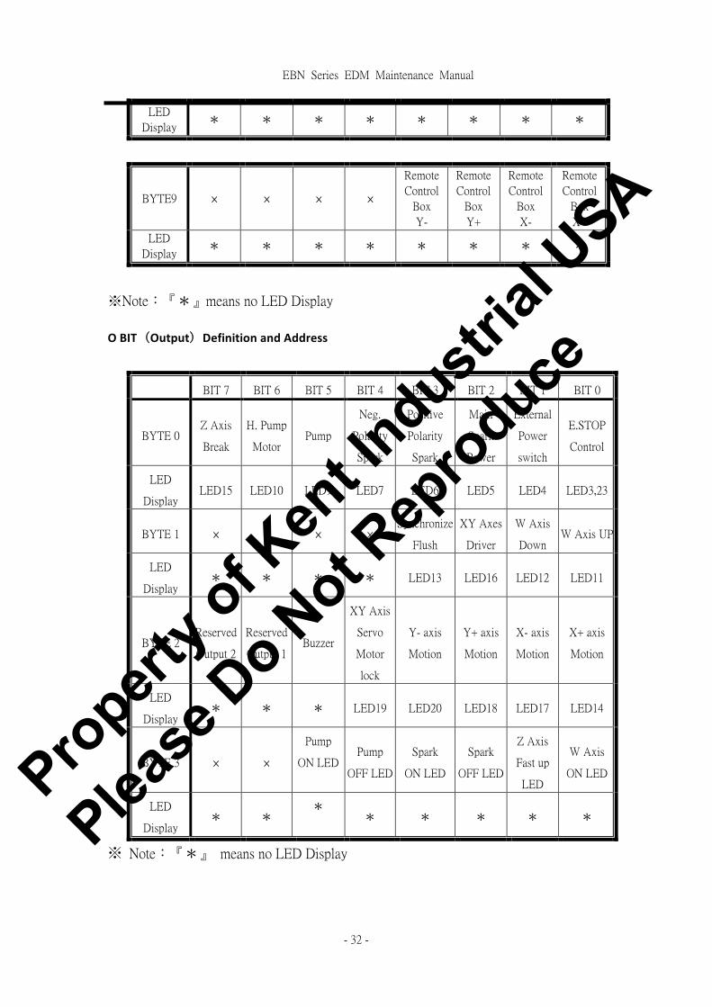
OBIT(Output)DefinitionandAddress
BIT 7 BIT 6 BIT 5 BIT 4 BIT 3 BIT 2 BIT 1 BIT 0
BYTE 0 Z Axis
Break
H. Pump
Motor Pump
Neg.
Polarity
Spark
Positive
Polarity
Spark
Main
Spark
Power
External
Power
switch
E.STOP
Control
LED
Display LED15 LED10 LED9 LED7 LED6 LED5 LED4 LED3,23
BYTE 1 × × × × Synchronize
Flush
XY Axes
Driver
W Axis
Down W Axis UP
LED
Display * * * * LED13 LED16 LED12 LED11
BYTE 2 Reserved
Output 2
Reserved
Output 1 Buzzer
XY Axis
Servo
Motor
lock
Y- axis
Motion
Y+ axis
Motion
X- axis
Motion
X+ axis
Motion
LED
Display * * * LED19 LED20 LED18 LED17 LED14
BYTE 3 × ×
Pump
ON LED Pump
OFF LED
Spark
ON LED
Spark
OFF LED
Z Axis
Fast up
LED
W Axis
ON LED
LED
Display * *
* * * * * *
※ Note:『*』 means no LED Display
Propert
y of K
ent In
dustrial
USA
Please
Do N
ot Rep
roduce
EBN Series EDM Maintenance Manual
- 33 -
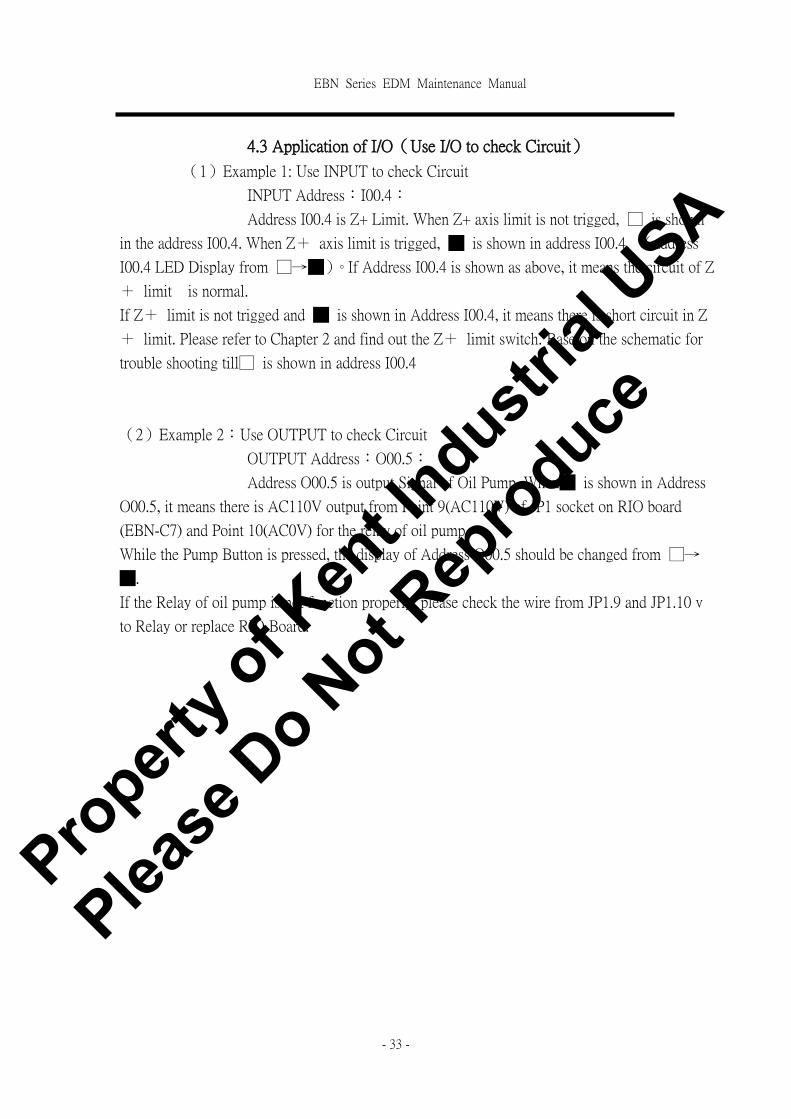
4.3 Application of I/O(Use I/O to check Circuit)
(1)Example 1: Use INPUT to check Circuit
INPUT Address:I00.4:
Address I00.4 is Z+ Limit. When Z+ axis limit is not trigged, □ is shown
in the address I00.4. When Z+ axis limit is trigged, █ is shown in address I00.4. (address
I00.4 LED Display from □→█)。If Address I00.4 is shown as above, it means the circuit of Z
+ limit is normal.
If Z+ limit is not trigged and █ is shown in Address I00.4, it means there is short circuit in Z
+ limit. Please refer to Chapter 2 and find out the Z+ limit switch. Base on the schematic for
trouble shooting till□ is shown in address I00.4
(2)Example 2:Use OUTPUT to check Circuit
OUTPUT Address:O00.5:
Address O00.5 is output Signal of Oil Pump. When█ is shown in Address
O00.5, it means there is AC110V output from Point 9(AC110V) of JP1 socket on RIO board
(EBN-C7) and Point 10(AC0V) for the relay of oil pump.
While the Pump Button is pressed, the display of Address O00.5 should be changed from □→
█.
If the Relay of oil pump is not function properly, please check the wire from JP1.9 and JP1.10 v
to Relay or replace RIO Board.
Propert
y of K
ent In
dustrial
USA
Please
Do N
ot Rep
roduce

EBN Series EDM Maintenance Manual
- 34 -
5 Controller Setting and Reference data JS EBN EDM Controller is a PC_BASE controller. There are some internal parameters
need to be preset.
5.1 Display System Parameter
Operation of display System Parameter Screen:
(1)Press【ESC】Key under Main screen and enter to system screen.
Fig 5.1 System Screen
Propert
y of K
ent In
dustrial
USA
Please
Do N
ot Rep
roduce

EBN Series EDM Maintenance Manual
- 35 -
(2)Press【F4 Parameter】and enter I/O Screen.
Fig 5.2 System parameter Screen
Propert
y of K
ent In
dustrial
USA
Please
Do N
ot Rep
roduce

EBN Series EDM Maintenance Manual
- 36 -
5.2 Description of System Parameter
ID Name of Parameter Default Description
1 END_PUMP_DISC 40 End distance of Electrode retract to
previous position (Unit: pulse)
2 END_PUMP_SPEED 5 End Speed percentage of Linear
PUMPING
3 PUMPING_F1 100 Electrode Retract Speed( 2nd Step)
(Unit: pulse/5ms)
4 PUMPING_F2 80 Electrode Retract Speed( 3rd Step)
(Unit: pulse/5ms)
5 TRAVEL_KI_GAIN 0 KI Gain of Z axis LM628 while
Traveling
6 TRAVEL_KD_GAIN 0 Differential Gain G of Feed Rate
7 TRAVEL_KP_GAIN 400 KP Gain of Z axis LM628 while
Traveling
8 TRAVEL_IL_GAIN 0 Reserved
9 SLOPE(UP,DOWN) 25 Slope of Z axis when Increase/
Decrease Speed
10 TRAVEL_SPEED 250 Travel Speed of G00
11 HOME_SPEED 300 Speed of Homing.
12 EDGE_SPEED 20 Feed Rate of EDGE
13 LAG_PROTECT_REF 200 Max. LAG Value. Alarm is ON
when LAG is greater than this value.
14 OPTICAL_SCALE 5 DRO Scale Value
15 MAXIMAL_CURRENT 60 Max. Spark Current
16 RESERVED4 0 Reserved
17 RESERVED3 0
18 RESERVED2 0 Reserved
19 RESERVED1 0 Reserved
20 RESERVED0 0 Reserved
! Note
*The parameters listed above are default value from manufacture. Change
any parameter might effect the performance.
If the parameters are changed by accident, please check the Parameter
Setting Table.
Propert
y of K
ent In
dustrial
USA
Please
Do N
ot Rep
roduce
EBN Series EDM Maintenance Manual
- 37 -
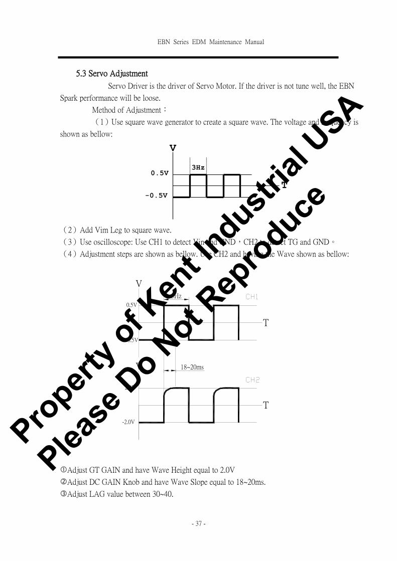
5.3 Servo Adjustment
Servo Driver is the driver of Servo Motor. If the driver is not tune well, the EBN
Spark performance will be loose.
Method of Adjustment:
(1)Use square wave generator to create a square wave. The voltage and frequency is
shown as bellow:
(2)Add Vim Leg to square wave.
(3)Use oscilloscope: Use CH1 to detect Vin and GND,CH2 to detect TG and GND。
(4)Adjustment steps are shown as bellow. Use CH2 and having the Wave shown as bellow:
�Adjust GT GAIN and have Wave Height equal to 2.0V
�Adjust DC GAIN Knob and have Wave Slope equal to 18~20ms.
�Adjust LAG value between 30~40.
T-0.5V
V
0.5V3Hz
3Hz
18~20ms
T
T
V
V
0.5V
-0.5V
2.0V
-2.0V
Propert
y of K
ent In
dustrial
USA
Please
Do N
ot Rep
roduce
EBN Series EDM Maintenance Manual
- 38 -
6 EBN Series EDM Trouble Shooting During the process of maintenance, please refer to the schematic of EBN ZNC
EDM machine in the maintenance manual. With the schematic in previous
chapters can help the technician for trouble shooting.
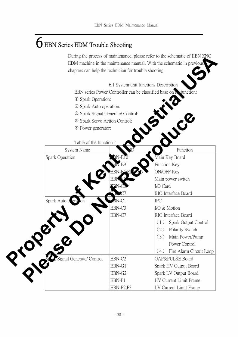
6.1 System unit functions Description
EBN series Power Controller can be classified base on its function:
� Spark Operation:
� Spark Auto operation:
� Spark Signal Generate/ Control:
� Spark Servo Action Control:
� Power generator:
Table of the function:
System Name ID Function
Spark Operation EBN-E10
EBN-E9
EBN-E5/EBN-E6
EBN-E11
EBN-C3
EBN-C7
Main Key Board
Function Key
ON/OFF Key
Main power switch
I/O Card
RIO Interface Board
Spark Auto operation EBN-C1
EBN-C3
EBN-C7
IPC
I/O & Motion
RIO Interface Board
(1)Spark Output Control
(2)Polarity Switch
(3)Main Power/Pump
Power Control
(4)Fire Alarm Circuit Loop
Spark Signal Generate/ Control EBN-C2
EBN-G1
EBN-G2
EBN-F1
EBN-F2,F3
GAP&PULSE Board
Spark HV Output Board
Spark LV Output Board
HV Current Limit Frame
LV Current Limit Frame
Propert
y of K
ent In
dustrial
USA
Please
Do N
ot Rep
roduce

EBN Series EDM Maintenance Manual
- 39 -
Spark Servo Action Control EBN-C3 Motion card
Power Supply Parts EBN-D1
EBN-D2
EBN-D3
EBN-J1
EBN-J2
(1)Provide HV/LV AC 3phase
Power.
(2)Provide Power of Pump
((1)Provide AC 110V Power
of Servo Controller
(2)Provide AC 110V Power of
Servo Motor
(1)Provide AC 110V Power of
Controller
(2)Provide AC 110V Power of
HV/LV Board
(3)Provide AC 110V Power of
Fan
(4)Provide AC 12V Power of
quartz Light
(1)Provide DC +12V, +5V
for RIO Interface Board.
(2)Provide AC 110V Power of
RIO Interface Board
Provide DC +12V, +5V for
HV/LV Board DC+5V、
DC+12V
Propert
y of K
ent In
dustrial
USA
Please
Do N
ot Rep
roduce

EBN Series EDM Maintenance Manual
- 40 -
6.2 Trouble Shooting and Maintenance Flow Chart
Please refer to operation manual, confirm the function of each key/ Signal LCD
for trouble shooting.
Please check the following item while the machine has problem:
(1)Status of problem:
� When machine has problem, the function key LED Light on panel
will be On or Off and the error message will show on screen.
� The status of machine motion.
� Position of working head╱Status of workpiece╱Status of Oil Tank
(2)Is operation process correct?
(3)Please check each abnormal unit and restart the power.
~ Danger
! Note
If the customer need the service from manufacturer, Please
provides the following information and fax it to JSEDM. Our
engineer will reply to you ASAP.
(1)Information on Machine Head:
Serial Number:
Date:
Model:
(2)Please use the name of component and parts described in
the operation manual and fax it to us:
� Describe the status of problems
� LED Light ON/OFF of each function key and the
Error Message on Screen.
� Position of working head and status of oil tank.
� Damaged component:
a. Name
b. Parts and location
c. Status of damage, such as burn out, broken and not
function.
� Times of problems happen.
1. Be aware of electrical shot while the machine is ON during
trouble shooting. Please turn off power while replace
components and unplug connector.
2. Before restart the power, please make sure each connect
point is connected properly.
Propert
y of K
ent In
dustrial
USA
Please
Do N
ot Rep
roduce

EBN Series EDM Maintenance Manual
- 41 -
6.2.1 Maintenance Flow Chart: Abnormal Machine Boot up
Case 1: when main power is ON, press【ON】 and can not turn on controller
EBN-C4
7A/30mm
LINEFILTER
LINE LOAD
LINE FILTER/10A
1
2
3 4
5
ON_SWITCH
P8[1..6]
SLOT5
EBN-D3.110V/6A
EBN-H1
PG+5V-12V+12VGNDGND
20
27
EBN-H1.27
P9:
EBN-D3.0V/6A
P9[1..6]
POWER-1[1..6]
EBN-H1EBN-H1.26
21
EBN-D3.0V/6A
17
AC110V[1..3]
EBN-H1.27
SLOT3
EBN-H1.26
26
EBN-H8
EBN-H1
EBN-E4
SLOT2
P8:
EBN-H7
SLOT6
Control board
POWER SUPPLY
GNDGND-5V+5V+5V+5V
EBN-D3.110V/6A
16
23
POWER-2[1..6]
EBN-H13 4
SLOT1SLOT4
EBN-C5
EBN-C7
22
Reference Schematic
※Refer to Schematic:EBN-C1.DSN、EBN-H1.DSN、EBN-E.DSN。
Propert
y of K
ent In
dustrial
USA
Please
Do N
ot Rep
roduce

EBN Series EDM Maintenance Manual
- 42 -
Trouble Shooting Flowchart
While pressing [ON] button(EBN-E4),
is there short circuit between EBN-H1.22
and EBN-H1.23? Replace 【ON】button(EBN-E4)。
Is there AC110V output
between EBN-H1.16 and
EBN-H1.17?
Replace Fuse 7A/30 ㎜(EBN-H7)。
Is there AC110V output
between EBN-H1.20 and
EBN-H1.21?
Does fuses 7A(EBN-H7)
blown out?
Replace RIO Interface Board(EBN-C7)。
Replace Small Transformer(EBE-D3)。
Is there AC110V output
between EBN-H1.26
andvEBN-H1.27?
Replace Relay(EBN-H8)。
Is there AC110V output on
Filter(EBN-C6)? Replace Filter(EBN-C6)。
Does the output of
POWER-1、POWER-2 from
power generator(EBN-C5)
normal?
Replace Power Generator
(EBN-C5)。
If the problem still not
removed, please check Case 2.
(Yes)
(No)
(Yes)
(No)
(Yes)
(No)
(Yes)
(No)
(Yes)
(No)
(No)
(Yes)
(Yes)
(No)
Propert
y of K
ent In
dustrial
USA
Please
Do N
ot Rep
roduce
EBN Series EDM Maintenance Manual
- 43 -
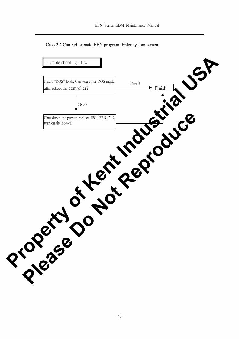
Case 2:Can not execute EBN program. Enter system screen.
Trouble shooting Flow
Chart
Shut down the power, replace IPC(EBN-C1),
turn on the power.
Insert ”DOS” Disk. Can you enter DOS mode
after reboot the controller? (Yes)
(No)
Finish
Propert
y of K
ent In
dustrial
USA
Please
Do N
ot Rep
roduce
EBN Series EDM Maintenance Manual
- 44 -
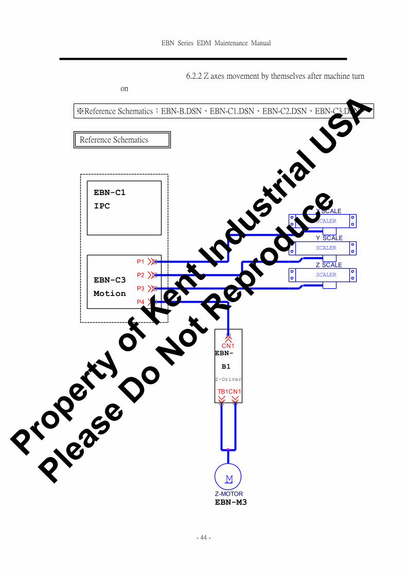
6.2.2 Z axes movement by themselves after machine turn
on
SCALER
Z SCALE
SCALER
Y SCALE
CN1
EBN-C3
B1
EBN-M3
Z-Driver
P2
P4
CN1
EBN-C1
TB1
EBN-
SCALER
X SCALEIPC
P3
P1
MZ-MOTOR
Motion
Reference Schematics
※Reference Schematics:EBN-B.DSN、EBN-C1.DSN、EBN-C2.DSN、EBN-C3.DSN。
Propert
y of K
ent In
dustrial
USA
Please
Do N
ot Rep
roduce

EBN Series EDM Maintenance Manual
- 45 -
Trouble Shooting flow chart
Shut down Main power, replace Motion card
(EBN-C3). Restart the machine. Does the
function normal?
(Yes)
(No)
Shut down Main power, replace IPC
(EBN-C1)). Restart the machine. Does the
function normal?
(No)
(Yes)
Check the following connection base on the Reference
Schematic above.
� From CON3 of EBN-C3 to CN1 of EBN1-B1.
� Z axis:CN1 of EBN-B1 to Z axis motor EBN2-M3
� Z axis DRO to P3 of EBE-C7.
Finish
Propert
y of K
ent In
dustrial
USA
Please
Do N
ot Rep
roduce
EBN Series EDM Maintenance Manual
- 46 -
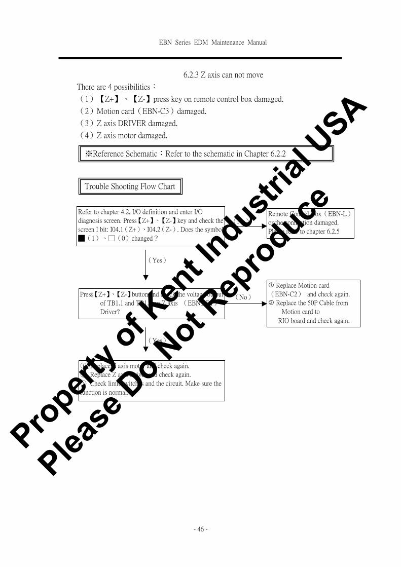
6.2.3 Z axis can not move
There are 4 possibilities:
(1)【Z+】、【Z-】press key on remote control box damaged.
(2)Motion card(EBN-C3)damaged.
(3)Z axis DRIVER damaged.
(4)Z axis motor damaged.
※Reference Schematic:Refer to the schematic in Chapter 6.2.2
Trouble Shooting Flow Chart
Refer to chapter 4.2, I/O definition and enter I/O
diagnosis screen. Press【Z+】、【Z-】key and check the
screen I bit: I04.1(Z+)、I04.2(Z-). Does the symbol
█(1)、□(0)changed?
(Yes)
(No) Remote Control Box(EBN-L)
or the connection damaged.
Please refer to chapter 6.2.5
(No) Press【Z+】、【Z-】button and check the voltage output
of TB1.1 and TB1.2 on Z axis (EBN1-B1)
Driver?
Does the output correct?
� Replace Motion card
(EBN-C2) and check again.
� Replace the 50P Cable from
Motion card to
RIO board and check again.
(Yes)
○1 Replace Z axis motor and check again.
○2 Replace Z axis Driver and check again.
○3 Check limit switches and the circuit. Make sure the
function is normal.
Propert
y of K
ent In
dustrial
USA
Please
Do N
ot Rep
roduce
EBN Series EDM Maintenance Manual
- 47 -
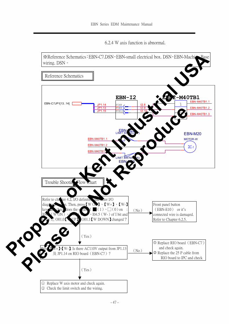
6.2.4 W axis function is abnormal.
JP1.15
EBN-M40TB1.3
EBN-C7JP1[13..14]
EBN2-M40TB1
EBN-M40TB1.2PIN10
M ~
EBN-M20MOTOR-W
JP1.13
EBN-I2
I2.10
EBN-M40TB1.1
2I2.9
3
EBN-M40TB1.1JP1.14
EBN-M40TB1.2
EBN-M40TB1.3
EBN-M23LIMIT SW/NC(DN)
PIN8 1
EBN-M22LIMIT SW/NC(UP)
I2.8PIN9
※Reference Schematics:EBN-C7.DSN、EBN-small electrical box. DSN、EBN-Machine Base
wiring. DSN。
Reference Schematics
Trouble Shooting Flow Chart
Refer to chapter 4.2, I/O definition and enter I/O
diagnosis screen. Then, press【W ON】、【W+】、【W-】
keys and check does the status of █(1)、□(0)on :
I04.3(W ON)、I04.4(W+)、I04.5(W-)of I bit and
O bit 之 O01.0【W UP】、O01.1【W DOWN】changed?
(Yes)
(No)
Front panel button
(EBN-E10) or it’s connected wire is damaged.
Refer to Chapter 6.2.5.
(No)
Press 【W+】、【W-】. Is there AC110V output from JP1.13
及 JP1.14 on RIO board(EBN-C7)?
� Replace RIO board(EBN-C7)
and check again.
� Replace the 25 P cable from
RIO board to IPC and check
again.
(Yes)
○1 Replace W axis motor and check again.
○2 Check the limit switch and the wiring.
Propert
y of K
ent In
dustrial
USA
Please
Do N
ot Rep
roduce

EBN Series EDM Maintenance Manual
- 48 -
6.2.5 Front Panel and Remote control box malfunction
FAQ of Front Panel:
(1)Press Key on Panel is not valid.
(2)LED is not ON
FAQ of Remote Control Box:
(1)Press Key on Remote Control Box is not valid.
(2)LED is not ON
10
5
P2[1..6]
3
Function Key
EBN-LP1[1..11]
6
Hard Key & Text Key
1
10
P1[1..6]
2
4
67
1111
7
2
EBN-C7P3[1..11]1
EBN-E9
9
5
8
EBN-C7P2[1..15]
EBE-I1REMOTE_CONNECTOR
9
RIO_PCB
EBN-E10P1[1..15]
4
REMOTE_PCB
8
3
※Reference Schematics:EBN-E.DSN、EBN-C1.DSN、EBN-C2.DSN。
Reference Schematics
Propert
y of K
ent In
dustrial
USA
Please
Do N
ot Rep
roduce

EBN Series EDM Maintenance Manual
- 49 -
For Front Panel:
Trouble shooting Flow Chart
Refer to Chapter 4.2, I/O definition and enter I/O diagnosis
screen. Press(HARD KEY)and check the LED . Does the
symbol █(1)、□(0)for I bit and O bit changed?
Replace RIO board(EBN-C7) and check again.
Replace EBN-E10 board and check again.
Replace IPC(EBN-C1)。
Normal (Yes)
(No)
(No)
(No)
(Yes)
(Yes)
Propert
y of K
ent In
dustrial
USA
Please
Do N
ot Rep
roduce

EBN Series EDM Maintenance Manual
- 50 -
Trouble Shooting Flow Chart for Remote Control Box:
Does the cable between EBN-C7JP3 to EBN-I1
and EBN-LP1 to EBN-I1 loose?
Refer to Chapter 4.2, I/O definition and enter
I/O diagnosis screen. Press the button of Remote
box and check the LED. Does the symbol █
(1)、□(0) for I bit and O bit changed?
Replace RIO board(EBN-C7) and check again.
Replace PC board(EBN-L) of remote control
box and check again.
Reconnect or replace the cable.。 (Yes)
(No)
(No)
Normal (Yes)
(No)
(No)
Replace IPC(EBN-C1)。
(Yes)
(Yes)
Propert
y of K
ent In
dustrial
USA
Please
Do N
ot Rep
roduce
EBN Series EDM Maintenance Manual
- 51 -
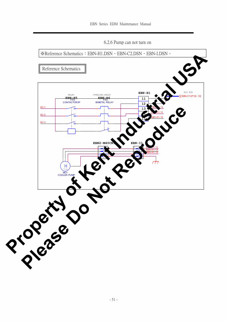
6.2.6 Pump can not turn on
AC-3
EBN-H1.14
4
EBN-C7JP1[9..10]
8EBN-H1.14
EBN-H5FR2
BIMETAL RELAY
7
EBN-H1.15
12
RIO PCB
9
EBN-H1
7
EBN2-M40CN3
AC-1
6
RELAY
6
14
11
3
11FR3CONTACTOR3P
AC-2
2
94
EBN-I1
OVERLOAD_RELAY
12
3
EBN-H1.13
EBN-H1.15
M~3
MO1COOLER PUMP
EBN-H6
13
8
EBN-H1.13
1
Reference Schematics
※Reference Schematics:EBN-H1.DSN、EBN-C2.DSN、EBN-I.DSN。
Propert
y of K
ent In
dustrial
USA
Please
Do N
ot Rep
roduce
EBN Series EDM Maintenance Manual
- 52 -
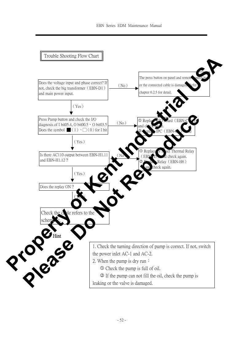
! Hint
Trouble Shooting Flow Chart
Does the voltage input and phase correct? If
not, check the big transformer(EBN-D1)
and main power input.
The press button on panel and remote control box
or the connected cable is damaged. Refer to
chapter 6.2.5 for detail.
Press Pump button and check the I/O
diagnosis of I bit05.4, O bit00.5、O bit03.5
Does the symbol █(1)、□(0)for I bit
and O bit changed?
Is there AC110 output between EBN-H1.11
and EBN-H1.12?
� Replace RIO board(EBN-C7)
and check again.
� Replace IPC(EBN-C1) and
check again.
(No)
(Yes)
(No)
(Yes)
Does the replay ON?
(No) � Replace or Reset Thermal Relay
(EBN-H5)and check again.
� Replace Relay(EBN-H6)
and check again.
(Yes)
Check the cable refers to the
schematic.
1. Check the turning direction of pump is correct. If not, switch
the power inlet AC-1 and AC-2.
2. When the pump is dry run:
� Check the pump is full of oil.
� If the pump can not fill the oil, check the pump is
leaking or the valve is damaged.
(Yes)
Propert
y of K
ent In
dustrial
USA
Please
Do N
ot Rep
roduce
EBN Series EDM Maintenance Manual
- 53 -
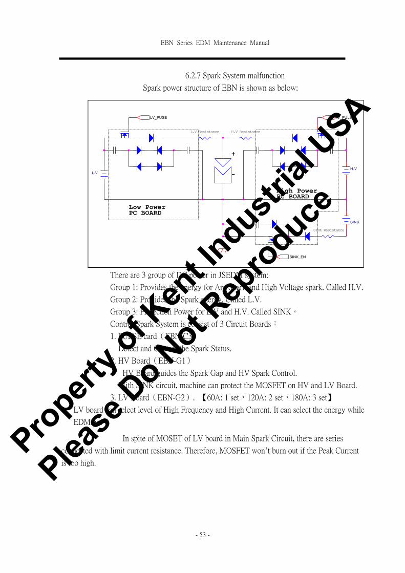
6.2.7 Spark System malfunction
Spark power structure of EBN is shown as below:
There are 3 group of DC power in JSEDM system:
Group 1: Provides the energy for Arc Spark and High Voltage spark. Called H.V.
Group 2: Provides the Spark energy. Called L.V.
Group 3: Protection Power for L.V and H.V. Called SINK。
Control Spark System is consist of 3 Circuit Boards:
1. PULSE card(EBN-C3)
Detect and Control the Spark Status.
2. HV Board(EBN-G1)
HV Board guides the Spark Gap and HV Spark Control.
With SINK circuit, machine can protect the MOSFET on HV and LV Board.
3. LV Board(EBN-G2). 【60A: 1 set,120A: 2 set,180A: 3 set】
LV board can select level of High Frequency and High Current. It can select the energy while
EDMing.
In spite of MOSET of LV board in Main Spark Circuit, there are series
connected with limit current resistance. Therefore, MOSFET won’t burn out if the Peak Current
is too high.
L.V
SINK Resistance
-
Low PowerPC BOARD
L.V Resistance
LV_PUSE
H.V Resistance
HV_PULSE
H.V
SINK
High PowerPC BOARD
+
SINK_EN
Propert
y of K
ent In
dustrial
USA
Please
Do N
ot Rep
roduce

EBN Series EDM Maintenance Manual
- 54 -
Description of each AC current and circuit:
H.V: Provides the energy for HV Board while guiding the spark gap and HV spark.
L.V: Provides the energy for LV Board while Sparking. The circuit is shown as below:
SINK:Provides the protection power for HV and LV board.
FAQ of Spark:
� Can not enter spark procedure.
� After press Spark button, Z axis moving up and down but with no spark.
� LV current too low.
� HV current too low.
� No voltage for LV.
� No voltage for HV.
� Arcing.
54EBN-D1.140V/4A
H.V+AC1
AC3
+
- 5K/100W
EBN-D1.140V/4A
EBN-D1.140V/4A
EBN-H21 EBN-H2
+
4700uF/200V
EBN-H19
53H.V-
L.V-
EBN-H18
57
AC1
AC3
+
-
+
4700uF/400VEBN-D1.65V/45A
56EBN-D1.65V/45A
EBN-D1.65V/45A
EBN-H21
5K/100W
L.V+
EBN-H2
51SINK-
SINK+
EBN-D1.35V/3A
AC1 +
-AC2
EBN-H2EBN-H17
EBN-D1.35V/3A
52
Propert
y of K
ent In
dustrial
USA
Please
Do N
ot Rep
roduce

EBN Series EDM Maintenance Manual
- 55 -
Can not enter Spark procedure:
Press Spark button, Z axis moving up and down but with no spark:
Trouble Shooting Flow
Chart
Does the short circuit LED ON?
Does the oil level to low while the Level
switch is pressed?
Does Z axis touch limit switch?
Does the working Coordinate exceed the
setting?
Is any message shown in Error message
Column?
Remove the problem of Short Circuit and
the LED is not ON. Check again.
� If EDMing with no submerge workpiece, set
the Level Control OFF.
� If EDMing with submerge workpiece, make
sure the oil level is reach to the setting.
Move the X、Y、Z and leave the limit
switch.
Reset the software limit value.
Trouble shooting for the Error message. If can’t.
reboot the machine and try again.
(No)
(Yes)
(Yes)
(No)
(Yes)
(No)
(Yes)
(No)
(Yes)
Trouble Shooting Flow Chart
Press Spark key. Is there DC200V output
between JP1.2 and JP1.3on PULSE board
(EBN-C2)? Replace PULSE board and check
again.
(Yes)
(No)
Check the cable between JP1 on PULSE
board and point 47, 48 on EBN-H2.
Propert
y of K
ent In
dustrial
USA
Please
Do N
ot Rep
roduce

EBN Series EDM Maintenance Manual
- 56 -
LV Current too low
HV current too low
No Voltage in LV
Trouble Shooting Flow Chart
Replace LV board(EBN-G2)and check
again. Is current still too low?
Replace PULSE board(EBN-C2)。
(No)
(Yes)
Normal
Trouble Shooting Flow
Chart
Replace HV board(EBN-G1) and check
again. Is current still too low?
Replace PULSE board(EBN-C2)。
(No)
(Yes)
Trouble Shooting Flow
Chart
� There is DC90 V output from Bridge
Rectifier (EBN-H18) on LV circuit.
� There is DC90V output from point 56,57 on
EBN-H2
Does the output described correct?
Replace the parts on LV circuit and
check again.
(No)
(Yes)
Follow the steps of Trouble Shooting Method -
LV Current too Low .
Normal
Propert
y of K
ent In
dustrial
USA
Please
Do N
ot Rep
roduce
EBN Series EDM Maintenance Manual
- 57 -
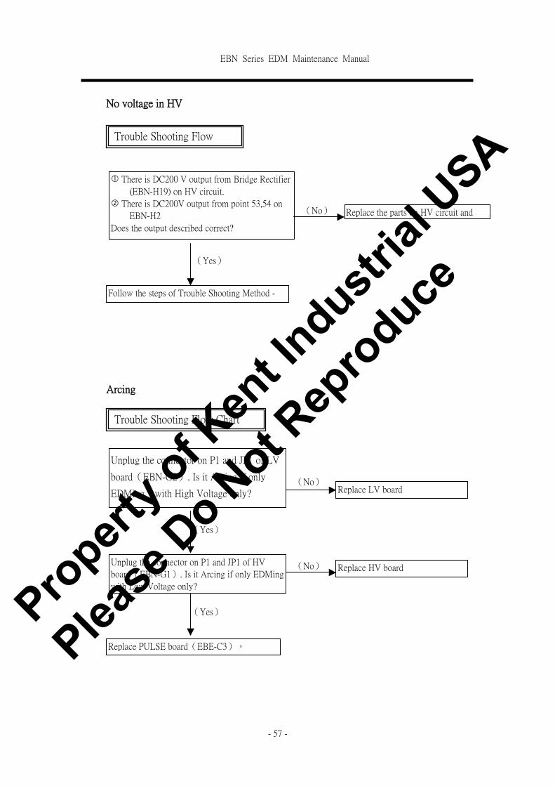
No voltage in HV
Arcing
Trouble Shooting Flow
Chart
� There is DC200 V output from Bridge Rectifier
(EBN-H19) on HV circuit.
� There is DC200V output from point 53,54 on
EBN-H2
Does the output described correct?
Replace the parts on HV circuit and
check again.
(No)
(Yes)
Follow the steps of Trouble Shooting Method -
HV Current too Low .
Trouble Shooting Flow Chart
Unplug the connector on P1 and JP1 of LV
board(EBN-G2). Is it Arcing if only
EDMing with High Voltage only?
Unplug the connector on P1 and JP1 of HV
board(EBN-G1). Is it Arcing if only EDMing
with Low Voltage only?
(Yes)
(No) Replace LV board
Replace PULSE board(EBE-C3)。
Replace HV board
(No)
(Yes) Propert
y of K
ent In
dustrial
USA
Please
Do N
ot Rep
roduce

EBN Series EDM Maintenance Manual
- 58 -
6.2.8 Polarity reverse switch malfunction
FR4CONTACTOR 4P
A
L4
L3
L2
L1 T1
T2
T3
T4
B
EBN-H14
EBN-H2
EBN-C7JP1.5
EBN-H13
43
POLE -
41
EBN-C7JP1.8
EBN-C7JP1.7
42
EBN-H2
+
FR5CONTACTOR 4P
A
L4
L3
L2
L1 T1
T2
T3
T4
B
EBN-C7JP1.6
44
POLE +
-
Trouble Shooting Flow
Chart
Reference Schematics
※Reference Schematics:EBN-H2.DSN、EBN-C1.DSN。
Polarity Selection described as follow:
� Relay(EBN-H14) is click when the Spark button is pressed.
� When the polarity is reversed as jump to the next step, the other relay
(EBN-H13)is click and EBE-H14 is released.
Does the relay(EBN-H13)acts as described above when the polarity is
reversed?
(No)
(Yes) If the relay is click but
can not spark normally, it
means the relay is bad
connection. Replace the
replay.
Is there AC110 output from point 43 and 44 on terminal(EBN-H2)?
(No)
(Yes)
If the relay is not
click, it means the
coil is bad. Replace
the relay.
Replace RIO board(EBN-C7)?
Propert
y of K
ent In
dustrial
USA
Please
Do N
ot Rep
roduce
EBN Series EDM Maintenance Manual
- 59 -
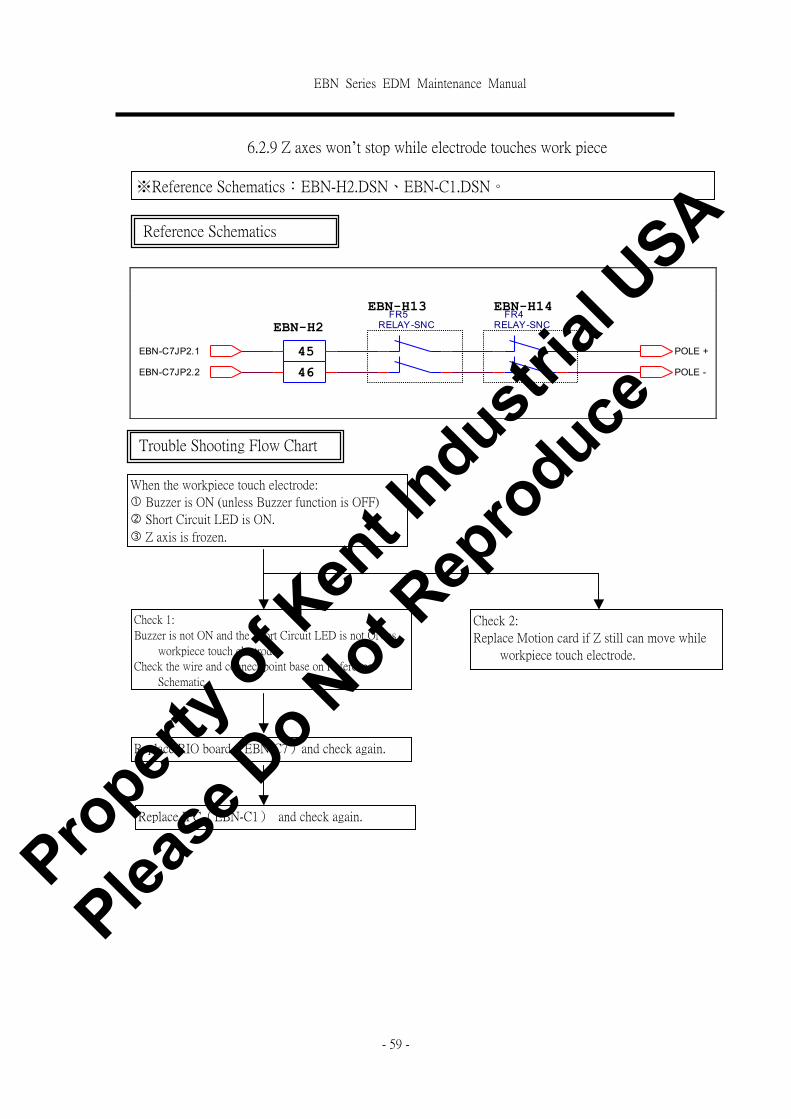
6.2.9 Z axes won’t stop while electrode touches work piece
FR5RELAY-SNC
EBN-C7JP2.2 46
EBN-H14
45POLE -
POLE +
EBN-H13
EBN-C7JP2.1
FR4RELAY-SNCEBN-H2
Reference Schematics
※Reference Schematics:EBN-H2.DSN、EBN-C1.DSN。
Trouble Shooting Flow Chart
When the workpiece touch electrode:
� Buzzer is ON (unless Buzzer function is OFF)
� Short Circuit LED is ON.
� Z axis is frozen.
Check 1:
Buzzer is not ON and the Short Circuit LED is not ON as
workpiece touch electrode.
Check the wire and connect point base on Reference
Schematic.
Replace RIO board(EBN-C7)and check again.
Check 2:
Replace Motion card if Z still can move while
workpiece touch electrode.
Replace IPC(EBN-C1) and check again.
Propert
y of K
ent In
dustrial
USA
Please
Do N
ot Rep
roduce

EBN Series EDM Maintenance Manual
- 60 -
6.2.10 Synchronize flush malfunction
Synchronize flush is ON when the following buttons is pressed.
(1)In Spark status, press key
(2)Press the function key【KEY 2】 Synchronize flush ON.
EBN2-M24
1 4 EBN-C7JP5.4 14 2
11
2
Synchronize Flush EBN2-M40CN3
14 4
EBN-I2
EBN-C7JP8.1 11 1
3 3
Reference Schematics
※Reference Schematics:EBN-C1.DSN、EBN-I.DSN、EBN-Electrical Box.DSN
Trouble Shooting Flow Chart
Press synchronize flush button and check the
I/O diagnosis. Does the symbol ▓(1)、□
(0)of I bit02.2 changed?
The button on front panel or the
connection is damaged. Refer to
chapter 6.2.5 for detail.。
Is there DC24V output from EBN-C7JP8.1
and EBE-C7JP5.4?
� Replace RIO board(EBN-C7)
and check again.
� Replace IPC(EBN-C1) and
check again.
Replace the relay of synchronize flush
(EBN2-M24).
(No)
(Yes)
(No)
(Yes)
Make sure the connected cable is not loose.
Propert
y of K
ent In
dustrial
USA
Please
Do N
ot Rep
roduce

EBN Series EDM Maintenance Manual
- 61 -
6.2.11 Oil Level Switch Malfunction
Level Control is ON when the following buttons is pressed.
(1)Press function key【KEY 1】, turn on Oil Level Function
(2)(2)Press key under Spark status.
EBN2-M40CN3
4
13
1
13 3
4 12 2 EBN-C7JP8.2
FLOAT_SWIT
CH 2 12 3
1 EBN-I2
EBN-C7JP5.6
EBN2-M25
Reference Schematics
※Reference Schematics:EBN-C1.DSN、EBN-I2.DSN、EBN-small electrical box.DSN。
Trouble Shooting Flow Chart
Press Level Control button and check the I/O
diagnosis. Does the symbol ▓(1)、□(0)
of I bit02.1 changed?
The button on front panel or the
connection is damaged. Refer to
chapter 6.2.5 for detail.
Is there DC24V output from EBN-C7J8.1 and
EBN-C7JP5.6?
� Replace RIO board(EBN-C7)
and check t again.
� Replace IPC(EBN-C1) and
check again.
Replace level switch(EBN2-M25)。
(No)
(Yes)
(No)
(Yes)
Make sure the connected cable is not loose. Propert
y of K
ent In
dustrial
USA
Please
Do N
ot Rep
roduce

EBN Series EDM Maintenance Manual
- 62 -
6.2.12 Work light is not ON
2
LAMP
EBN-H12 EBN-H11
EBN-H1
EBN-I2
F4 7A/30mm
EBN2-M40CN2
32
35
2
AC1 +
- AC2
BD1 KBPC2506/25A
EBN2-M7
AC12V/2A
1
EBN-D3
1 AC0VV/2A
Reference Schematics
※Reference Schematics:EBN-C2.DSN、EBN-I.DSN、EBN-H1.DSN、EBN-D.DSN。
Trouble Shooting Flow Chart
Does the fuse EBN-H12
(F4/7A)ok? Replace fuse(EBN-H12)。
(Yes)
(No)
Is there AC12V output from
small transformer EBN-D3?
(Yes)
(No) Replace small transformer
(EBN-D3)。
Is there AC12V output from
EBN2-M40CN2 for quartz
light?
(No)
(Yes)
Check the circuit loop is in
good connection.
Is quartz light EBN-M7
blown out? (Yes)
Replace quartz light
(EBN-M7)
Propert
y of K
ent In
dustrial
USA
Please
Do N
ot Rep
roduce
EBN Series EDM Maintenance Manual
- 63 -
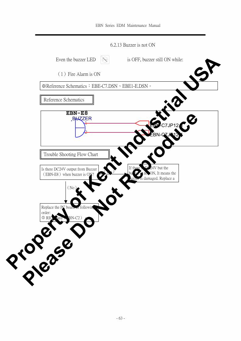
6.2.13 Buzzer is not ON
Even the buzzer LED is OFF, buzzer still ON while:
(1)Fire Alarm is ON
1 EBN-C7JP12.3
2
EBN-E8
EBN-C7JP12.4
¸BUZZER
Reference Schematics
※Reference Schematics:EBE-C7.DSN、EBE1-E.DSN。
Trouble Shooting Flow Chart
Is there DC24V output from Buzzer
(EBN-E8)when buzzer is ON?
(No)
(Yes) If there is DC24V but the
buzzer is not ON, It means the
buzzer is damaged. Replace a
new buzzer.
Replace the PC board as following
order:
� RIO board(EBN-C2)。
� IPC(EBN-C1)。
Propert
y of K
ent In
dustrial
USA
Please
Do N
ot Rep
roduce

EBN Series EDM Maintenance Manual
- 64 -
6.2.14 Fire Alarm is not function
Cover the photo sensor by hand for couple seconds. Turn the photo sensor toward light
source and uncover it. The following fire alarm action should appear:
(1)Fire Alarm LED is ON
(2)Spark Power off
(3)Buzzer is ON with a short interval break.
Turn on (EBN2-M7) and REST fire alarm signal. The machine will back to normal.
※Reference Schematic:EBN-C1.DSN、EBN-small electrical box.DSN。
Trouble Shooting Flow Chart
Replace the PC board as following order. Restart the
machine and check again.
� RIO board(EBN-C7)。
� IPC(EBN-C1)。
Replace Photo Sensor if the machine still not
working normally after replacing the PC board.
Propert
y of K
ent In
dustrial
USA
Please
Do N
ot Rep
roduce

Kent Industrial USA, Inc.1231 Edinger Ave., Tustin, CA 92780Tel: (714) 258-8526 | Fax: (714) 258-8530Toll-free: 1-800-KENT-USA (1-800-536-8372)E-mail: [email protected]