Embed Size (px)
DESCRIPTION
Indian Railway Wagon
Citation preview

¼Hkkjr ljdkj½
GOVERNMENT OF INDIAjsYk ea=ky; ¼ jsYkos cksMZ ½
Ministry of Railways (Railway Board)
Maharajpur, Gwalior – 474005 (INDIA)Ph: 0751 -2470314 & Fax: 0751 -2470841
MAINTENANCE MANUAL FOR
WAGONS(DRAFT)
¼ ½
IRCAMTECH/GWL/MECH/WMM/1.0December 2013
Draft

FOREWORD
1. The Maintenance manual for Wagons was last compiled and issued by Ministry of
Railways in 2001. 2. During the last decades, considerable work has been done in upgrading the
wagons to meet the traffic demand for higher productivity. Thus, it has become necessary to update the Wagon Maintenance Manual incorporating the technological upgradations/innovations brought out in the wagon design, maintenance strategy and operation over Indian Railways.
3. The manual deals with maintenance of all systems of the wagons like
superstructure, running gear, braking system, etc. Thus, it can act as the single bare reference document for maintenance of wagons in workshops and open line depots. In this manual, the attempt is not to cover the entire range of individual working conditions, which may exist on the various zonal railways. The zonal railways may, if considered necessary, supplement these instructions with subsidiary procedures based on local practices with the approval of CME.
4. Technological upgradation is a continuing process. Those that have been
implemented are covered in this manual. With IR’s thrust in increased productivity and market orientation, emphasis on factors such as increased throughput in terms of higher axle load and speeds, product specific designs, enhanced reliability and availability etc. will gather momentum ushering in newer designs and technological upgradation of wagons more than ever before. Therefore, separate maintenance instructions will also be issued as and when the newer designs are inducted in to the system.
5. This manual has been written with the purpose of knowledge dissemination and
guidance of staff dealing with repairs and maintenance of wagons. Hence full use of the same must be made to derive the intended benefits fully.
6. Apart from detailed maintenance instructions for the different types of wagons
now on IR, this manual also lists out various rules and provisions given in IRCA Part-III as a supplement for reference purposes. Statutory provisions and instructions contained in the general rules and various codes are to be followed and remain unaffected by the issue of this manual.
( Alok Johri )
Member Mechanical, Railway Board
New Delhi, dated December 23, 2013
Draft

PREFACE
A comprehensive wagon maintenance manual was published in 2001. A lot of developments have since taken place such as introduction of new wagon stock, stainless steel wagons, permissible loading up to CC+8+2t, introduction of premium examination, introduction of bogie mounted Air brake system(BMBS), Twin pipe air brake system etc,. As a result, the maintenance pattern and requirements have changed considerably. This has necessitated revision of existing wagon maintenance manual.
Railway Board nominated a committee of officers comprising of Executive Director/CAMTECH/GWL, ED(Wagon)/RDSO/LKO, CRSE/C.Rly/Mumbai and CWM/WRS/KTT vide letter No. 2008/M(N)/951/28 dated 30.10/03.11.2008 for updation and revision of “Indian Railways Unified Maintenance Manual for Wagons”. The revision and updation of manual has been completed taking into account latest fleet of freight stock currently running on Indian Railways.
The present manual bridges this gap and covers detailed treatise of above mentioned issues. The other salient features of the manual are as follows:
A new chapter titled “INFRASTRUCTURE FACILITIES FOR MAINTENANCE OF FREIGHT STOCK ” has been included in the manual.
The manual has been divided into logical chapters covering various sub-assemblies and systems. The constructional details and functioning has been explained before describing the detailed maintenance procedures.
The important dimensions, clearances, material specifications, drawing references etc. have been given immediately after the paragraphs where they have been referred to while describing maintenance procedures.
Clear sketches and isometric views of the important sub-assemblies/components have been given in the manual.
For convenience of indexing of reference, the paragraphs have been numbered according to a 3 /4 figure “Code”, in which the last two figures give the number of the paragraphs and the remaining figures the number of the chapter. Thus paragraph 101 of any code is paragraph 1 of chapter 1 of that code and paragraph 1103, paragraph 3 of chapter 11.
The page number in each chapter in this manual starts from 1. The reader can easily identify the chapter number to which a page belongs by reading the footer of the page at the bottom where chapter number as well as chapter title is given. This scheme of page numbering is adopted to provide flexibility of easily revising the chapters in future, on account of design or procedure changes or induction of new stock without disturbing the page numbers of succeeding chapters.
The tables in each chapter consist of two numbers separated by a decimal point. The number before decimal point indicates the chapter number whereas the number after the decimal point indicates the running serial number of the table which start from 1 in every chapter. The convention adopted for numbering the figures is also identical to the numbering scheme adopted for the tables.
Draft

The items of maintenance required to be carried out in sickline, ROH & POH have
been listed out separately towards the end of various chapters under appropriate headings for each system/subassembly covered in the manual for easy reference and guidance of maintenance units.
Future addition/ deletion/ modification to this manual will be processed by RDSO and will be require approval of the Railway Board.
The Committee is thankful to shri D.K. Saraf, AMM/Plg., Railway Board, shri Ashesh Agrawal, EDME(Fr.), Railway Board, shri Anirudh Kumar, Director/wagon, RDSO, shri Roopesh Kohli, Director/wagon, RDSO and Shri K.P.Yadav, Director/Mechanical, CAMTECH for their valuable contribution in finalisation of this manual. Members of the committee also express their appreciation for the valuable assistance provided by shri V.K.Agrawal the then Director/Wagon/RDSO and shri K.S. Jain, Director Wagon/RDSO/LKO and Shri Sanjeev Kumar Sr.CTA/CAMTECH & Shri R.K.Dwivedi Sr CTA/CAMTECH.
Draft

CONTENTS
FOREWORD i PREFACE ii CONTENTS iii CORRECTION SLIPS ISSUED iv
CHAPTER 1
INTRODUCTION Page 1-52 101. General 1 102. Important parameters of Wagons 2 103. Important Rule Books and References 5 104. Standard Infrastructure for Wagon Depot 7 105. Important Wagon Modifications 7 106. Numbering Convention in the Manual 7 107. Numbering of Tables and Figures in the Manual 7 108. Standard Features of Wagons 7 Appendix 8-52
CHAPTER 2 MAINTENANCE WARRANTY AND CONDEMNATION Page 1-21 201. Warranty Inspection of newly built wagons 1 202. Examination and Maintenance Periodicity 6 203. ROH of Wagons with CASNUB Bogie 7 204. Categorization of Wagon repair 8 205. Condemnation of Wagons 10 206. POH and ROH Interval 12 207. Work Areas where attention to be given 13 Table 2.3 15-21
CHAPTER 3 YARD MAINTENANCE Page 1-37 301. Pattern of Freight Train Examination 1 302. Notification of Examination Points 1 303. Frequency of Intensive Examination for different Stock 1 304. Steps of Intensive Examination 2 305. Details of Intensive Examination 2 306. Air Brake Testing 6 307. Important Parameters to be ensured during Intensive Examination 7 308. Important Parameters to be ensured during Sick Line/ Depot Attention 8 309. Common Problems in Bogie Mounted Brake System and Remedies 10 310. Infrastructure & Facilities required in the yard 13 311. Machinery & Plant items 13 312. Tools Required 13
Draft
313. Man Hours for various types of Examinations 13 314. Procedure Order for running of Goods Trains 14 315. Procedure for Examination & Safety Certification of Departmental Rolling Stock 15 316. Premium Examination 16 317 CC Rakes 17 318 Post Loading & Post Tippling Examination 18 319 GDR Check 19 320 Examination of Container Trains (BLC/BLL Rakes) 21 Format –I 25-28 Format –II 29-31 Format- III 32-35 Table 3.3 36 Table 3,4 37
CHAPTER 4 WAGON BODY Page 1-28 401. Introduction 1 402. General Construction of Open Wagon 1 403. General Construction of Covered Wagon 1 404. General Construction of Flat Wagon & Well Wagon 2 405. General Construction of Hopper Wagon 2 406. Nature of Repairs required in Wagon body 3 407. Corrosion in Wagon Body 3 408. Anticorrosive Measures 4 409. Rejectable Defects 4 410. Repairs in Sickline and ROH Depot 4 410A Panel Patching 4 410B Procedure for Welded Patches 6 410C Riveted Patch 10 410D Repairs to Bulged ends 10 410E Repairs to Body Structural members (Stanchions, Carlines & Copings) 10 410F Water Tightening of Wagons 10 410G Repairs to Doors and Door fittings (for Mild Steel wagons) 11 410H Repairs to Doors & Door fittings (for BCNHL Wagons) 12 410I Cleaning, Surface preparation & Painting 20 411. Repair and Maintenance in Workshops during POH and NPOH 21 412. Important Precautions to be taken while carrying out welding 21 413. Important Do’s and Don’ts 22 414. Maintenance of Stainless Steel Wagons 22 415. Upgraded rehabilitation of BOXN to BOXNR 22 416. Lock Bolts 24 417. New Wagon Numbering Scheme 26-28
CHAPTER 5 UNDER FRAME Page 1-14 501. General 1 502. General Construction of BG Wagon Underframe 1
Draft

503. Need of the repairs to Bogie Wagon Underframe for mild steel wagons 9 504. Repair Procedure 9 505. Cleaning and De-rusting of the Underframe 10 506. Repairs to Head Stock 10 507. Repairs to Diagonals and Cross Bars 10 508. Repairs to Sole Bars 10 509. Repairs to Floor Plate 11 510. Underframe of Brake Van 11 511. BVZI Brake Van 11 512. List of Modifications 12 513. Repair and Maintenance in Sickline and ROH Depot 14 514. Repair and Maintenance in Workshop during POH/NPOH 14
CHAPTER 6 BOGIES AND SUSPENSION Page 1-34 601. CASNUB Bogie 1 602-605. Fabricated BOX Bogie (UIC) 15 606. Wheel Assembly 16 607. Grease for CTRBs 25 608 Maintenance & Repair of Cartridge Tapered Roller Bearings 26-34
CHAPTER 7 AIR BRAKE SYSTEM Page 1-133 701. Classification of Air Brake System 1 702. Principle of Operation of Single Pipe Graduated Release Air Brake System 1 702A Principle of Operation of Twin Pipe Graduated Release Air Brake System 4 703. Common Pipe Bracket 6 704. Intermediate Piece (Sandwich piece) 7 705. Brake Pipe Hose 7 706. Brake Pipe Coupling 7 707. Cut Off Angle Cock 10 708. Brake Cylinder 13 709. Dirt Collector 18 710. Auxiliary Reservoir 22 711. Guard’s Emergency Brake Valve 23 712. Slack Adjuster 26 713. Distributor Valve 38 714. C3W Distributor Valve 38 715. Testing of Distributor Valve 52 715A Purpose of conducting various tests 53 715B Tools and Equipments for Testing 56 716. Testing of C3W Distributor Valve 56 717. KE Distributor Valve 61 718. Testing of KE Distributor Valve 70 719. Test Report Proforma for C3W/KE Distributor Valve 73 720. Single Wagon Test 75 721. Rake Test 79
Draft

722. Repair and Maintenance in Sickline 82 723. Repair and Maintenance in ROH 83 724. Periodical Overhaul of Air Brake System 86 725. Details of Tools, Fixtures and Equipments 88 726. Brake Power Calculations for BOXN wagon 91 727. Brake Rigging 92 728. Composition Brake Block 97 729. Bogie Mounted Brake System (BMBS) 99-133
CHAPTER 8 DRAW AND BUFFING GEAR Page 1-36 801. General 1 802. Centre Buffer Coupler and Draft Gear 1 803. Parts of Centre Buffer Coupler Assembly 2 804. Inspection of CBC 2 805. Inspection of Draft Gear (MK-50 & RF-361) 4 806. Removal of Coupler and Draft Gear from Wagons 5 807. Coupler Reclamation Practices 6 808. CBC Measuring Gauges and their Applications 9 809. Development of High Tensile Coupler & High Capacity Draft Gear 17 810. RF-361 Draft Gear 18 811. Maintenance of Mark-50 Draft Gear 26 Vendor List 31 Marking on CBC (Manufacturers Initial) 35-36
CHAPTER 9 TANK WAGON Page 1-29 901. Constructional Details 1 902. Periodicity of Overhauling of Tank Wagon 4 903. Steam Cleaning of Bitumen and Molasses tank Wagons 6 904. Cleaning of Tanks for Corrosive Liquids 6 905. Inspection of Tank Barrels 7 906. Testing of Barrel 8 907. Barrel Test Pressure 8 908. Testing of Tanks used for Corrosive Liquids 9 909. Testing of Tank Wagons used for Petrol and Middle Distillates of 9 Petroleum and Vegetable Oils 910. Repairs to Tank Barrels by Welding 9 911. Repairs and Testing of Tank Barrel Mounting Fittings 13 912. Fittings of Tanks for Corrosive Liquids 14 913. Fittings of Tank Wagons of Petrol, other inflammable products, vegetable oils, etc. 14 914. Test Reports and Records of Inspection 15 915. Important Modifications 15 916. Painting and Lettering 15 917. Examination and Repair of Tank Wagons by C&W Supervisor in sick line 18 918. Precautions with leaky Tank Wagons 18 919. Precautions to be taken at Loading and Unloading Points (Tanks as Pressure Vessels) 20
Draft
920. Loading and Unloading Corrosive Liquids 22 921. Loading and Unloading of Tank Wagons 23 922. Precautions for Tanks for Petroleum and other inflammable products 23 923. Precautions for Bitumen Tanks 25 924. Maintenance and Repair in Sick line 25 925. Maintenance and Repair in Workshop during POH 26 926 Instruction for maintenance & Operation of Bogie petrol tank wagon type BTPN 27 927 Prevention of fire risks due to proximity of sealing wires with contact wire of OHE. 28 Table 9.5: List of RDSO maintenance publications for Tank Wagons 29
CHAPTER 10
SPECIAL TYPE OF WAGONS Page 1-12 1001 BOXNCR WAGONS 1 1002. BOGIE LOW PLATFORM CONTAINER FLATS (BLC) 3 1003. BROAD GAUGE BOGIE CONTAINER FLAT WAGON (BLLA & BLLB) 6-12
CHAPTER 11
INFRASTRUCTURE FACILITIES Page 1-12 1101 Introduction 1 1102. Infrastructure and facilities required in the Yards 2 1103 Infrastructural Facilities for Freight Examination Yard with World-Class 4 Facilities for detachment-free Yard 1104 Infrastructural Facilities in Air Brake ROH Depots 5 1105 Facilities required for maintenance of Stainless Steel Wagons 11 1106 Minimum infrastructure required for Premium & CC examination 12
LIST OF APPENDICES
APPENDIX-I TIPPLER 1 to 6 APPENDIX-II LIST OF IMPORTANT MODIFICATIONS TO BE CARRIED OUT ON FREIGHT STOCK 1 to 2 APPENDIX-III WAGON MANUFACTURERS AND WORKSHOPS 1 to 4 APPENDIX-IV BRANDING DETAILS ON WHEEL AND AXLE 1 APPENDIX-V LIST OF MUST CHANGE ITEMS IN FREIGHT STOCK DURING POH AND ROH 1 to 5 APPENDIX-VI GUIDELINES FOR MAINTENANCE AND REPAIR OF STAINLESS STEEL WAGONS 1 to 14
Draft

CHAPTER 1- INTRODUCTION Page 1 of 53
WAGON MAINTENANCE MANUAL
(WAGON MAINTENANCE MANUAL- 2013)
CHAPTER - 1
INTRODUCTION
Draft

CHAPTER 1- INTRODUCTION Page 2 of 53
WAGON MAINTENANCE MANUAL
CHAPTER 1
INTRODUCTION
101. GENERAL
A comprehensive Wagon Maintenance Manual was published in 2001. A lot of developments have taken place such as introduction of new stock, stainless steel wagons, permissible loading up to CC+8t+2t, introduction of premium examination, introduction of bogie mounted Air brake system, Twin pipe air brake system etc,. As a result, the maintenance pattern and requirements have changed considerably. This has necessitated revision of existing wagon maintenance manual.
a) For ensuring optimum performance of wagon fleet, it is necessary that:
Preventive maintenance is given timely to avoid occurrence of defects Defects are attended effectively and well in time so that the wagons
remain fit for traffic use till the next schedule falls due Detention during examination and repairs is kept to minimum Frequent failures of similar nature are studied and necessary
modifications/ design changes are effected to eliminate the cause of such failure.
In course of time and based on experience, various procedures/
schedules for maintenance of wagons have been prepared. The schedules and procedures have been largely standardized and issued by Railway Board, RDSO, and IRCA etc. However, in many cases, instructions have been issued in piecemeal. This manual consolidates various standing instructions issued on wagon maintenance and lays down guidelines for ensuring uniformity in the practices to be followed on various railways. The important aspects of wagon maintenance have been covered and wherever necessary, the references are indicated so that the reader can refer these, if necessary, for detailed instructions and procedures not contained in this manual.
b) This manual does not deal with the special stock or ODCs for which separate
instructions are issued by RDSO/manufacturers. c) At the end of this chapter, the list of important instructions and references has
been given. Throughout this manual, wherever IRCA Part III has been mentioned, it refers to IRCA Part-III (Latest edition).
d) While proper maintenance plays a vital role in ensuring effectiveness of the
rolling stock, an equally crucial role is played by proper handling and careful operation of the wagon fleet so as to minimise the incidences of damage and subsequent need for repairs.
Draft

CHAPTER 1- INTRODUCTION Page 3 of 53
WAGON MAINTENANCE MANUAL
e) The CRT’s and other four wheeler stock other than tank wagon and brake van have been completely phased out therefore details of this type of stock have been completely deleted.
f) The operation of MG stock, vacuum brake UIC and four wheeler tank wagons
have reduced considerably and are likely to be phased out in next few years, details of these stock have also been deleted. The 2001 version of wagon maintenance manual may be referred whenever necessary.
102. IMPORTANT PARAMETERS OF WAGONS
The important dimensions and sketches of main type of wagons stock used over Indian Railways are enclosed at the end of this chapter. Details of UIC/ Vacuum Brake/ Four wheeler and Meter Gauge/ NG stock have been omitted. For maintenance of these stocks, wagon maintenance manual ver. 2001 may be referred. Details of following new type of wagon stock have been added. Regarding latest position of axle load, spring configuration and permissible speed RDSO’s instructions may be referred. The speed certificates of these wagons are available on RDSO ‘s website.
TABLE 1.1 OPEN WAGONS
Designation Axle
Load Bogie Springs Permissible Speed
Loaded/Empty Remarks
BOY 22.9 t Casnub 22 NLB (modified)
O – 14 I – 10 S – 4
65/ 75 Kmph It has no doors. Designed for heavy minerals.
BOYEL 25.0 t Casnub 22 NLC O – 14 I – 14 S – 4
50/ 65 Kmph Min. wheel tread dia. 950 mm.
BOXN 20.32 t Casnub 22 NLB O – 12 I – 8 S – 4
75/ 80 Kmph Operation at CC +6 +2/ CC +8 +2 allowed as interim measure, with speed restriction 60/80
BOXN M1 22.82 t Casnub 22 NLB (Modified)
O – 14 I – 10 S – 4
70/ 80 (CC +6 +2) 60/ 80 (CC +8 +2) Kmph
On specified routes the speed is 75/80 Kmph with CC +8 +2
BOXNEL 25.0 t Casnub 22 NLC O – 14 I – 14 S – 4
50/ 65 Kmph Min. wheel tread dia. 950 mm
BOXNHS 20.32 t Casnub 22 HS O – 14 I – 12 S – 4
100/ 100 Kmph -
BOXNHS M1 22.82 t Casnub 22 HS (Modified)
O – 14 I – 14 S – 4
75/ 90 (CC +6 +2) 60/ 90 (CC +8 +2) Kmph
On specified routes the speed is 75/80 Kmph with CC +8 +2
BOXNHA 22.1 t IRF 108 HS O – 14 I – 14 S – 4
100/100 Kmph (20.32 & 22.1 t) 75/100Kmph(22.82 t)
-
BOXNLW 20.32 t Casnub 22 HS O – 14 I – 12 S – 4
100/ 100 Kmph Stainless steel (IRS: M44) and Corton Steel (IRS: M41) used in body & under frame
BOXNLW M1 22.82 t Casnub 22 HS (Modified)
O – 14 I – 14 S – 4
60/ 65 Kmph -
BOXNHL 22.9 t Casnub 22 HS O – 14 I – 14 S – 4
75/ 100 Kmph IRS: M44 (Body), Flat centre Pivot, K type CBB, Improved Coupler & draft gear Br. Cyl, 300 mm, IRSA 750 Slack Adj., A.R. 75 litres, PU Painting (Phirozi colour)
Draft

CHAPTER 1- INTRODUCTION Page 4 of 53
WAGON MAINTENANCE MANUAL
Designation Axle Load
Bogie Springs Permissible Speed Loaded/Empty
Remarks
BOST 20.32 t Casnub 22 HS
O – 14 I – 12 S – 4
75/ 80 Kmph Operation at CC+ 6 + 2 allowed as an interim measure with speed restriction to 50/ 80
BOSTM1 22.32 t Casnub 22 HS (modified)
O – 14 I – 14 S – 4
60/ 65 Kmph High Axle load version of BOST
BOSTHS 20.32 t Casnub 22 HS (mod- I)
O – 12 I – 12 S – 4
100/ 100 Kmph High Speed version of BOST
BOSTHS M1 22.32 t Modified Casnub 22 HS (Mod- I)
O – 14 I – 14 S – 4
60/ 80 Kmph High Axle load version of BOST HS
BOSTHS M2 22.32 t Modified Casnub 22 HS (Mod- II)
O – 12 I – 12 S – 4
60/ 100 Kmph Design of suspension is different than BOSTHS M1.
BOXNHAM 22.82 t IRF 108 HS O – 14 I – 14 S – 4
75/ 100 Kmph -
BOXNR 22.9 t IRF 108 HS O – 12 I – 8 S – 4
75/ 80 Kmph -
TABLE 1.2 COVERED WAGONS
Designation Axle Load
Bogie Springs Permissible Speed ( in Kmph)
Remarks
BCN 20.32 t Casnub 22 NLB
O – 12 I – 8 S – 4
75/ 80 Kmph Permitted with CC +6 +2 also.
BCN M1 22.82 t (Modified) Casnub 22 NLB
O – 14 I – 10 S – 4
75/ 80 (CC +6 +2) 65/ 80 (CC +8 +2) Kmph
High axle load version of BCN
BCNHS M1 22.82t Modified) Casnub 22 HS
O – 14 I – 14 S – 4
75/ 90 (CC +6 +2) 75/ 90 (CC +8 +2) Kmph
High axle load version of BCNHS
BCNA 20.32 t Casnub 22 NLB O – 12 I – 8 S – 4
80/ 80 Kmph Permitted with CC +6 +2 also.
BCNA M1 22.82 t (Modified) Casnub 22 NLB
O – 14 I – 10 S – 4
75/ 80 (CC +6 +2) 65/ 80 (CC +8 +2) Kmph
High axle load version of BCNA
BCNAHS 20.32 t Casnub 22 HS O – 14 I – 12 S – 4
100/ 100 Kmph Variant of BCNA with Casnub bogie 22 HS bogie
BCNAHS M1 22.82 t (Modified) Casnub 22 HS
O – 14 I – 14 S – 4
75/ 100 (CC +6 +2) 75/ 100 (CC +8 +2) Kmph
High axle load version of BCNA HS
BCNHL 22.9 t Casnub 22 HS
O – 14 I – 14 S – 4
65/ 65 Kmph Length reduced, width and height increased than BCNA. No. of wagons/ rake = 58 IRS: M44 body, Flat centre Pivot, K-type CBB, improved coupler & draft gear, Brake cylinder 300 mm, IRSA 750 slack adjuster, A.R. 75 liters, PU painting (Phirozi).
BCCN End wagon A Middle Wagon B
10.425 t 10.50 t
IRF 106 HS O – 14 I – nil S – 4
100 Kmph Maruti Car Double decker
BCCW 20.32 t Casnub 22 NLB
O – 12 I – 8 S – 4
70 Kmph (Specific Route)
Cement Wagon
BCCW 21.82 t Casnub 22 HS
O – 14 I – 14 S – 4
65 Kmph
Cement Wagon
BCBFG 21.82 t Casnub 22HS (Mod.1)
O – 14 I – 14 S – 4
75 Kmph (Specific Route)
Food Grain hopper wagon
Draft

CHAPTER 1- INTRODUCTION Page 5 of 53
WAGON MAINTENANCE MANUAL
TABLE 1.3 FLAT WAGONS
Designation Axle
Load Bogie Springs Permissible speed Remarks
BRN 20.32 t Casnub 22 NLB
O – 12 I – 8 S – 4
75/ 80 Kmph Designed for rails and heavy steel products.
BRNA 20.32 t Casnub 22 NLB O – 12 I – 8 S – 4
75/ 80 Kmph Improved version of BRN, Higher pay to tare ratio.
BRNAHS 20.32 t Casnub 22 HS O – 14 I – 12 S – 4
100/ 100 Kmph High speed variant of BRNA
BFNS 20.32 t Casnub 22 HS
O – 14 I – 12 S – 4
100/ 100 Kmph Designed for transportation of steel coils, plates, sheets & billets etc.
BRHNEHS 20.32 t Casnub 22 HS O – 14 I – 12 S – 4
65/ 65 Kmph Bogie rail wagon designed for Track Relaying trains (TRT) specially for loading RCC sleepers.
TABLE 1.4 HOPPER WAGONS
Designation Axle Load
Bogie Springs Permissible Speed Remarks
BOBSN 22.9 t (modified) Casnub 22 NLB
O – 14 I – 10 S – 4
75/ 75 Kmph Designed in 1994 for transportation of Iron ore, side discharge.
BOBSN M1 25 t Casnub 22 NLC
O – 14 I – 14 S – 4
50/ 60 Kmph High axle load variant of BOBSN. Casnub 22 NLC Bogie.
BOB R 20.32 t Casnub 22 NLB
O – 12 I – 8 S – 4
80/ 80 Kmph Designed in 1986 for coal. Bottom discharge. No. of wagons/ rake = 53.
BOBR M1 22.32 t (Modified) Casnub 22 NLB
O – 14 I – 10 S – 4
70/ 75 Kmph (CC + 6 + 2) version of BOBR.
BOB RN 20.32 t Casnub 22 NLB O – 12 I – 8 S – 4
70/ 75 Kmph Designed in 1991 by reducing the length of BOBR. No. of wagons/ rake = 58.
BOBRN M1 22.32 t (Modified) Casnub 22 NLB
O – 14 I – 10 S – 4
70/ 80 Kmph (CC + 6 + 2) version of BOBRN.
BOBRNHS M1
22.32 t (Modified) Casnub 22 HS
O – 14 I – 14 S – 4
60/ 65 Kmph --
BOBRNEL 25 t Casnub 22 NLC O – 14 I – 14 S – 4
50/ 65 Kmph 25 t axle load. Wheel dia 1000 mm. POH–6 years, ROH–2 years.
BOBYN 20.32 t Casnub 22 NLB
O – 12 I – 8 S – 4
75/ 75 Kmph Air Brake version of BOBY. Designed in 1996
BCBFG 21.82 t Casnub 22 HS (Mod-I)
O – 12 I – 12 S – 4
75/ 75 Kmph Bogie covered Hopper Wagon for food grains. Designed with automatic LSD.
Draft

CHAPTER 1- INTRODUCTION Page 6 of 53
WAGON MAINTENANCE MANUAL
TABLE 1.5 TANK WAGONS
Designation Axle Load
Bogie Springs Permissible Speed Remarks
BTALN 20.32 t UIC Bogie -- 65/ 65 Kmph Bogie Ammonia Tank Wagon BTPN 20.32 t Casnub 22 NLB O – 12
I – 8 S – 4
80/ 75 Kmph(Loaded) Bogie POL Tank Wagon
BTPGLN 19.8 t Casnub 22 NLB O – 12 I – 8 S – 4
75/ 80 Kmph Bogie LPG Tank Wagon. Variant of BTP GL with Air Brakes / Casnub 22 NLB bogie.
BTCS 20.32 t Casnub 22 W
O – 12 I – 8 S – 4
65/ 65 Kmph Bogie Caustic Soda Tank Wagon. Provisional speed certificate is with casnub 22W bogie. In 2007, bogie altered to NLB in the drawing.
BTAP 20.32 t Casnub 22 NLB O – 12 I – 8 S – 4
65/ 65 Kmph Bogie Alumina Tank Wagon.
BTFLN 20.32 t Casnub 22 HS O – 14 I – 12 S – 4
65/ 65 Kmph (Provisional)
Bogie POL Tank Wagon
TABLE 1.6 CONTAINER WAGONS
Designation Axle
Load Bogie Springs Permissible Speed Remarks
BLLA/ B 20.32 t LCCF 20 (c) O – 14 I – 12 S – 4
100/ 100 Kmph Bogie low platform longer container flat wagon.
BLCA/ B 20.32 t
LCCF 20 (c) O – 14 I – 12 S – 4
100/ 100 Kmph Bogie low platform container flat wagon
BLCAM/ BLCBM
22 t Modified LCCF 20 (c)
O – 14 I – 14 S – 4
90/ 100 Kmph In 2007, bogie of BLC wagon was modified by providing upgraded side bearer, upgraded friction wedge, and two additional inner springs for double stack container operation.
BCACM 20.32 t LCCF 20 (c) O – 14 I – 12 S – 4
65/ 75 Kmph For auto car industry
TABLE 1.7 BRAKE VAN
Designation Axle
Load Bogie Springs Permissible Speed Remarks
BVZI 5.875 t ICF Bogie - 100 Kmph Designed in 2000 with ICF Bogie to achieve comfortable ride, 5 m longer than BVZC.
BVZC 14.0 t 4- wheeler - 100 Kmph RDSO Drg. No. WD- 81035/S-2
103. IMPORTANT RULE BOOKS AND REFERENCES
List of Technical Monographs/Instructions relevant to maintenance of Freight stock are included in the compendium of instructions/ technical monographs issued vide Railway Board’s letter No. 2004/M(N)/951/16 Dt. 18.5.2004. The following rule books, pamphlets and monographs contain information required to supplement this manual. These may be referred to for details, if not available in this manual.
Draft

CHAPTER 1- INTRODUCTION Page 7 of 53
WAGON MAINTENANCE MANUAL
SNo IRCA publication Description
Latest edit ion/
correction
1 IRCA
Conference Rules Part III
Rules for Maintenance, Examination & Interchange of Goods Stock of Indian Government Railways (Latest edition)
SNo RDSO publication Description
Latest edit ion/
correction 1 G-52 Code of Practice for Rubber lining of Hydrochloric
acid Tank Barrel Nov.1967
2 G-55H Instructions for maintenance & Operation of Hydrochloric acid tank wagon type 'THA'
Aug.1976
3 G-62 Maintenance manual of Alliance II Coupler June.1977 4 G-65 Maintenance manual for 4-wheeled liquefied
petroleum gas tank wagon type 'TPGLR' (Preliminary)
July-2003
5 G-66 Maintenance manual for TSA & MBTSA 1983 6 G-70 Maintenance manual for BOXN Aug.1998 7 G-71 Maintenance manual for Phosphoric acid Tank
Wagon Feb.1999
8 G-72 General Std. Spec. For Fabrication of Wagon 'U' frame & Bogies
Oct.2001 & Corrigendum No.1 of Nov. 2002.
9 G-73 Operation and Maintenance Manual for BOBR/BOBRN
Rev.I of oct.2005
10 G-76 Inspection and Maintenance of CBC for Line Staff 1987 11 G-79 Inspection and Maintenance of BTAL /BTALN April.1999 12 G-80 Inspection and Maintenance of CBC for Workshop 1989 13 G-81 Inspection and Maintenance of Cartridge Roller
Bearing fitted on Casnub Bogie Feb.2000
14 G-86 Maintenance Manual for Bogie Liquefied Petroleum Gas Tank Wagon type BTPGL
Dec.1999
15 G-90 Maintenance and Operating Instruction for Bogie Petroleum Tank Wagon type 'BTPN'
July.2012
16 G-95 Instructions for Inspection and Maintenance for Casnub Bogies
June.2003
17 G-97 Maintenance Manual for Air Brake System for Freight Stock
July 2001
18 G-100 Technical Pamphlet for Instructions & Maintenance of Automatic Twist Lock (ATL) devices fitted on Container flat wagons.
July.2010 & May.2012
19 G-103 Technical Pamphlet on strengthening of underframe, repair of critical weld joints, repair of centre sill, Centre girders and sole bar cracks
Nov.2010 May.2011(Rev.2)
20 WT-77-I Instructions for inspection and maintenance of 20.3 tonne Roller Bearing axle boxes fitted on wagon.
Dec.1985
21 WT-79-I Instructions for inspection and maintenance of 16.3 tonne Roller Bearing axle boxes fitted on wagon.
1987
22 R-7 Instructions for Rectification of Welding Defect on Bogie frame (BOX Wagon)
Sep.1963
Draft

CHAPTER 1- INTRODUCTION Page 8 of 53
WAGON MAINTENANCE MANUAL
104. STANDARD INFRASTRUCTURE FOR WAGON DEPOT A separate Chapter No 11 for standard infrastructure required in wagon depots has
been added. 105. IMPORTANT WAGON MODIFICATIONS
The list of important modifications to be carried out on freight stock is given in Appendix-II.
106. NUMBERING CONVENTION IN THE MANUAL
For convenience of indexing of reference, the paragraphs have been numbered according to a 3 /4 figure “Code”, in which the last two figures give the number of the paragraphs and the remaining figures the number of the chapter. Thus paragraph 101 of any code is paragraph 1 of chapter 1 of that code and paragraph 1103, paragraph 3 of chapter 11.
The page number of each chapter in this manual starts from 1. The reader can easily identify the chapter number to which a page belongs by reading the header of the page where chapter number as well as chapter title is given. This scheme of page numbering is adopted to provide flexibility of easily revising the chapters in future, on account of design or procedure changes or induction of new stock without disturbing the page numbers of succeeding chapters.
107. NUMBERING OF TABLES AND FIGURES IN THE MANUAL The tables in each chapter consist of two numbers separated by a decimal point. The
number before decimal point indicates the chapter number whereas the number after the decimal point indicates the running serial number of the table which starts from 1 in every chapter. The convention adopted for numbering the figures is also identical to the numbering scheme adopted for the tables.
108. STANDARD FEATURES OF WAGONS
Important features and lay out of the wagons are given in the following appendix-A.
Technical data and other important parameters are also available in this appendix for ready reference.
Draft

CHAPTER 1- INTRODUCTION Page 9 of 52
WAGON MAINTENANCE MANUAL
FIG. BOXN WAGON (RDSO Drg. No. WD- 80007/ S-2)
INTRODUCTION: - BOXN wagon has been designed for transportation of iron ores, coal etc. either fitted with Casnub-22W/ Casnub-22W(M)/Casnub 22 NLB bogies, non-transition center buffer couplers and single-pipe graduated release air brake system.
STANDARD FEATURES OF ‘BOXN’ WAGON
S.No PARTICULARS Parameter S.No PARTICULARS Parameter 1 Length over head stock (mm) 9784 14 Cubic Capacity (Cu.M) 56.29 2 Length over couplers (mm) 10713 15 Maximum axle load (tonne) 20.32 3 Length inside (mm) 9784 16 Tare Weight (tonne) 23.2 4 Width inside/Width Overall (mm) 2950/3200 17 Pay load (tonne) 58.08 5 Height inside/Height (max.) from RL. 1950/3233 18 Gross load (Pay+Tare) (tonne) 81.28 6 Bogie centers (mm) 6524 19 Ratio gross load/Tare 3.5 7 Journal length × dia. (mm) 144x278 20 Ratio (Pay load to tare) 2.5 8 Journal centers (mm) 2260 21 Track Loading density (tonnes/meter) 7.59 9 Wheel dia. on tread (New/Worn) (mm) 1000/906 22 No. of wagons per train 58 10 Height of C.B.C. from R.L. (mm) 1105 23 Brake System Air Brake 11 C.G. from R.L. (empty) (m) 1.016 24 Coupler C.B.C. 12 C.G. from R.L. (loaded) (m) 1.974 25 Bearing CTRB 13 Floor area (Sq.M) 28.87 26 Maximum Speed (Loaded)/ Empty 75 kmph /80 kmph
WAG
ON
MAIN
TENAN
CE M
ANU
AL
APPE
DIX
Draft

CHAPTER 1- INTRODUCTION Page 10 of 52
WAGON MAINTENANCE MANUAL
FIG. BOXNCR WAGON (RDSO Drg. No. WD- 80007/ S-2)
INTRODUCTION: - The wagon is a variant of BOXN wagon with its body in IRS M-44 steel. It’s under frame is however made of mild steel. This has been done to provide better corrosion resistance to wagon body. All parameters of this wagon are same as that of BOXN wagon.
STANDARD FEATURES OF ‘BOXNCR’ WAGON
S.No PARTICULARS Parameter S.No PARTICULARS Parameter 1 Length over head stock (mm) 9784 14 Cubic Capacity (Cu.M) 56.29 2 Length over couplers (mm) 10713 15 Maximum axle load (tonne) 20.32 3 Length inside (mm) 9784 16 Tare Weight (tonne) 23.2 4 Width inside/Width Overall (mm) 2950/3200 17 Pay load (tonne) 58.08 5 Height inside/Height (max.) from RL. 1950/3233 18 Gross load (Pay+Tare) (tonne) 81.28 6 Bogie centers (mm) 6524 19 Ratio gross load/Tare 3.5 7 Journal length × dia. (mm) 144x278 20 Ratio (Pay load to tare) 2.5 8 Journal centers (mm) 2260 21 Track Loading density (tonnes/meter) 7.59 9 Wheel dia. on tread (New/Worn) (mm) 1000/906 22 No. of wagons per train 58 10 Height of C.B.C. from R.L. (mm) 1105 23 Brake System Air Brake 11 C.G. from R.L. (empty) (m) 1.016 24 Coupler C.B.C. 12 C.G. from R.L. (loaded) (m) 1.974 25 Bearing CTRB 13 Floor area (Sq.M) 28.87 26 Maximum Speed (Loaded)/ Empty 75 kmph / 80 kmph
Draft

CHAPTER 1- INTRODUCTION Page 11 of 52
WAGON MAINTENANCE MANUAL
FIG. BOXNNHA WAGON (RDSO Drg. No. WD- 98015 - S- 02)
INTRODUCTION: - This wagon has been designed for transportation of coal to axle load of 22.1t. It has higher sidewalls compared to BOXN wagon.
STANDARD FEATURES OF ‘BOXNHA’ WAGON S.No PARTICULARS Parameter S.No PARTICULARS Parameter 1 Length over head stock (mm) 9784 14 Cubic Capacity (Cu.M) 62.8 2 Length over couplers (mm) 10713 15 Maximum axle load (tonne) 22.1 3 Length inside (mm) 9784 16 Tare Weight (tonne) 23.17 4 Width inside/Width Overall (mm) 2950/3200 17 Pay load (tonne) 65.23 5 Height inside/Height(max.) from RL. 2175/3450 18 Gross load (Pay+Tare) (tonne) 88.4 6 Bogie centers (mm) 6524 19 Ratio gross load/Tare 3.82 7 Journal length × dia. (mm) 144x278 20 Ratio (Pay load to tare) 2.82 8 Journal centers (mm) 2260 21 Track Loading density (tonnes/meter) 8.25 9 Wheel dia. on tread (New/Worn) (mm) 1000/906 22 No. of wagons per train 58 10 Height of C.B.C. from R.L. (mm) 1105 23 Brake System Air Brake 11 C.G. from R.L. (empty) (m) - 24 Coupler C.B.C. 12 C.G. from R.L. (loaded) (m) - 25 Bearing CTRB 13 Floor area (Sq.M) 28.87 26 Maximum Speed (Loaded)/ Empty 75 kmph / 80 kmph
Draft

CHAPTER 1- INTRODUCTION Page 12 of 52
WAGON MAINTENANCE MANUAL
FIG. BOXNHS WAGON (RDSO Drg. No. WD – 80007/S- 2)
INTRODUCTION: - The wagon is variant of BOXN wagon with operating speed of 100 kmph in empty and 100 kmph in loaded condition. In this wagon high speed bogies have been provided. The other parameters of this wagon are same as of BOXN wagon.
STANDARD FEATURES OF ‘BOXNHS’ WAGON S.No PARTICULARS Parameter S.No PARTICULARS Parameter 1 Length over head stock (mm) 9784 14 Cubic Capacity (Cu.M) 56.29 2 Length over couplers (mm) 10713 15 Maximum axle load (tonne) 20.32 3 Length inside (mm) 9784 16 Tare Weight (tonne) 23.2 4 Width inside/Width Overall (mm) 2950/3200 17 Pay load (tonne) 58.08 5 Height inside/Height (max.) from RL. 1950/3233 18 Gross load (Pay+Tare) (tonne) 81.28 6 Bogie centers (mm) 6524 19 Ratio gross load/Tare 3.5 7 Journal length × dia. (mm) 144x278 20 Ratio (Pay load to tare) 2.5 8 Journal centers (mm) 2260 21 Track Loading density (tonnes/meter) 7.59 9 Wheel dia. on tread (New/Worn) (mm) 1000/906 22 No. of wagons per train 58 10 Height of C.B.C. from R.L. (mm) 1105 23 Brake System Air Brake 11 C.G. from R.L. (empty) (m) 1.016 24 Coupler C.B.C. 12 C.G. from R.L. (loaded) (m) 1.974 25 Bearing CTRB 13 Floor area (Sq.M) 28.87 26 Maximum Speed (Loaded)/ Empty 100 kmph / 100 kmph
Draft

CHAPTER 1- INTRODUCTION Page 13 of 52
WAGON MAINTENANCE MANUAL
FIG. BOXN (LW) WAGON (RDSO Drg. No. WD –88088- S - 02)
INTRODUCTION: - To meet the requirement of higher pay to tare ratio, this bogie open wagon was designed in 1988. Cold Rolled Formed (CRF) sections and stainless steel/carton steel are used in design to reduce the tare weight of the wagon.
STANDARD FEATURES OF ‘BOXN (LW)’ WAGON S.No PARTICULARS Parameter S.No PARTICULARS Parameter 1 Length over head stock (mm) 9784 14 Cubic Capacity (Cu.M) 61.09 2 Length over couplers (mm) 10713 15 Maximum axle load (tonne) 20.32 3 Length inside (mm) 9784 16 Tare Weight (tonne) 18.26 4 Width inside/Width Overall (mm) 3022/3250 17 Pay load (tonne) 63.02 5 Height inside/Height (max.) from RL. 2066/3341 18 Gross load (Pay+Tare) (tonne) 81.28 6 Bogie centers (mm) 6524 19 Ratio gross load/Tare 4.45 7 Journal length × dia. (mm) 144x278 20 Ratio (Pay load to tare) 3.45 8 Journal centers (mm) 2260 21 Track Loading density (tonnes/meter) 7.59 9 Wheel dia. on tread (New/Worn) (mm) 1000/906 22 No. of wagons per train 58 10 Height of C.B.C. from R.L. (mm) 1105 23 Brake System Air Brake 11 C.G. from R.L. (empty) (m) - 24 Coupler C.B.C. 12 C.G. from R.L. (loaded) (m) - 25 Bearing CTRB 13 Floor area (Sq.M) 29.57 26 Maximum Speed (Loaded)/ Empty 100 kmph / 100 kmph
Draft

CHAPTER 1- INTRODUCTION Page 14 of 52
WAGON MAINTENANCE MANUAL
FIG. BOXNHL WAGON (RDSO Drg. No. WD –05086- S - 02)
INTRODUCTION: - This bogie open wagon was designed at 22.9t axle load and 250mm longer than BOXNHS wagon. The wagon is manufactured by using stainless steel and cold rolled sections.
STANDARD FEATURES OF ‘BOXNHL’ WAGON S.No PARTICULARS Parameter S.No PARTICULARS Parameter 1 Length over head stock (mm) 10034 14 Cubic Capacity (Cu.M) 61.05 2 Length over couplers (mm) 10963 15 Maximum axle load (tonne) 22.9 3 Length inside (mm) 10034 16 Tare Weight (tonne) 20.6 4 Width inside/Width Overall (mm) 3022/3250 17 Pay load (tonne) 71.0 5 Height inside/Height (max.) from RL. 2028/3301 18 Gross load (Pay+Tare) (tonne) 91.6 6 Bogie centers (mm) 6690 19 Ratio gross load/Tare 4.45 7 Journal length × dia. (mm) 144x278 20 Ratio (Pay load to tare) 3.45 8 Journal centers (mm) 2260 21 Track Loading density (tonnes/meter) 8.35 9 Wheel dia. on tread (New/Worn) (mm) 1000/906 22 No. of wagons per train 58 10 Height of C.B.C. from R.L. (mm) 1105 23 Brake System Air Brake 11 C.G. from R.L. (empty) (m) - 24 Coupler C.B.C. 12 C.G. from R.L. (loaded) (m) - 25 Bearing CTRB 13 Floor area (Sq.M) 30.32 26 Maximum Speed (Loaded)/ Empty 75 kmph / 100 kmph
Draft
CHAPTER 1- INTRODUCTION Page 15 of 52
WAGON MAINTENANCE MANUAL
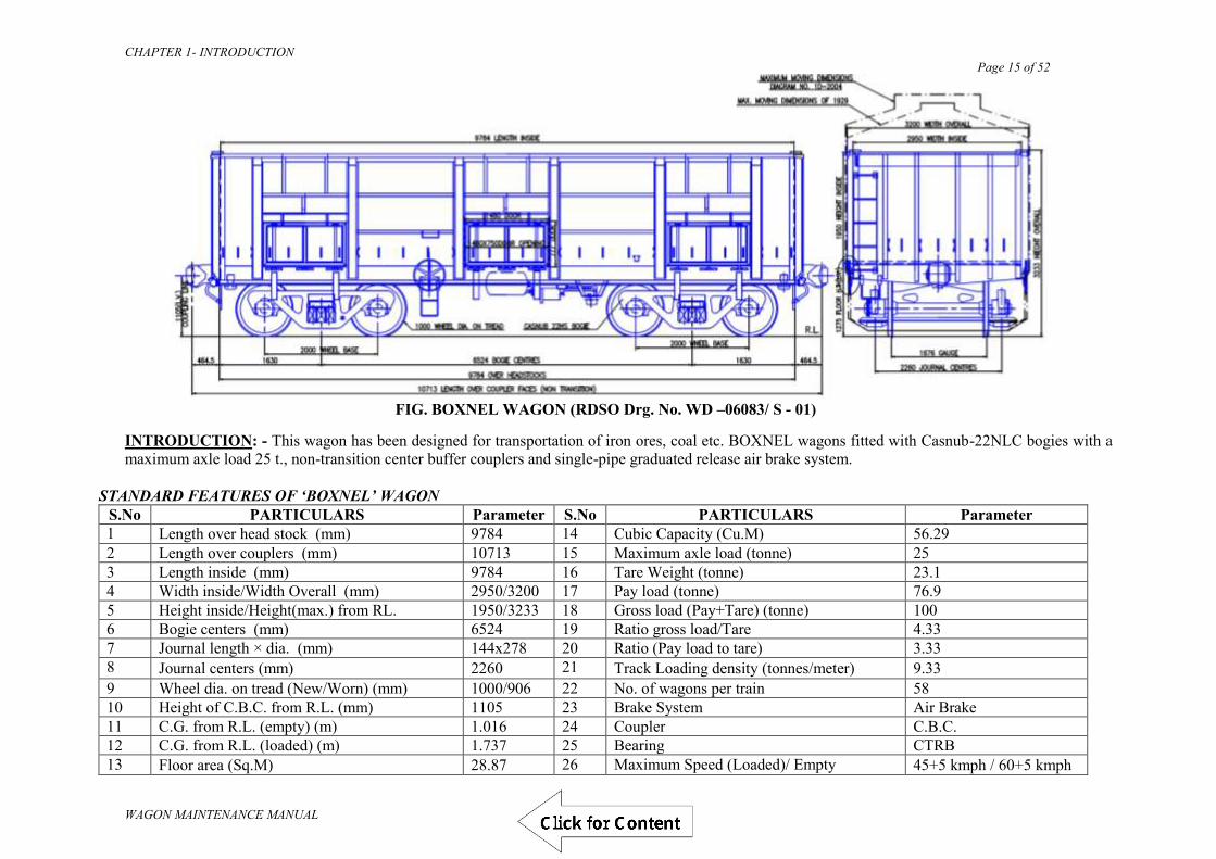
FIG. BOXNEL WAGON (RDSO Drg. No. WD –06083/ S - 01)
INTRODUCTION: - This wagon has been designed for transportation of iron ores, coal etc. BOXNEL wagons fitted with Casnub-22NLC bogies with a maximum axle load 25 t., non-transition center buffer couplers and single-pipe graduated release air brake system.
STANDARD FEATURES OF ‘BOXNEL’ WAGON S.No PARTICULARS Parameter S.No PARTICULARS Parameter 1 Length over head stock (mm) 9784 14 Cubic Capacity (Cu.M) 56.29 2 Length over couplers (mm) 10713 15 Maximum axle load (tonne) 25 3 Length inside (mm) 9784 16 Tare Weight (tonne) 23.1 4 Width inside/Width Overall (mm) 2950/3200 17 Pay load (tonne) 76.9 5 Height inside/Height(max.) from RL. 1950/3233 18 Gross load (Pay+Tare) (tonne) 100 6 Bogie centers (mm) 6524 19 Ratio gross load/Tare 4.33 7 Journal length × dia. (mm) 144x278 20 Ratio (Pay load to tare) 3.33 8 Journal centers (mm) 2260 21 Track Loading density (tonnes/meter) 9.33 9 Wheel dia. on tread (New/Worn) (mm) 1000/906 22 No. of wagons per train 58 10 Height of C.B.C. from R.L. (mm) 1105 23 Brake System Air Brake 11 C.G. from R.L. (empty) (m) 1.016 24 Coupler C.B.C. 12 C.G. from R.L. (loaded) (m) 1.737 25 Bearing CTRB 13 Floor area (Sq.M) 28.87 26 Maximum Speed (Loaded)/ Empty 45+5 kmph / 60+5 kmph
Draft
CHAPTER 1- INTRODUCTION Page 16 of 52
WAGON MAINTENANCE MANUAL
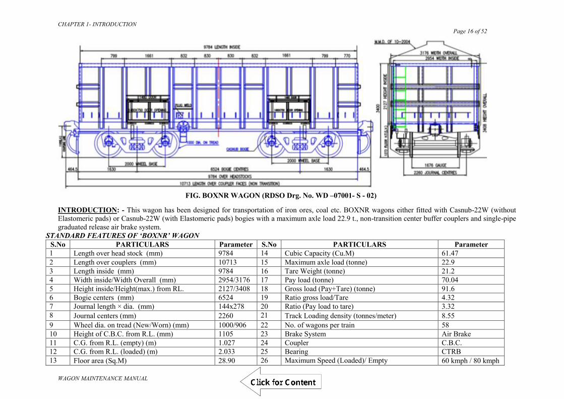
FIG. BOXNR WAGON (RDSO Drg. No. WD –07001- S - 02)
INTRODUCTION: - This wagon has been designed for transportation of iron ores, coal etc. BOXNR wagons either fitted with Casnub-22W (without Elastomeric pads) or Casnub-22W (with Elastomeric pads) bogies with a maximum axle load 22.9 t., non-transition center buffer couplers and single-pipe graduated release air brake system.
STANDARD FEATURES OF ‘BOXNR’ WAGON S.No PARTICULARS Parameter S.No PARTICULARS Parameter 1 Length over head stock (mm) 9784 14 Cubic Capacity (Cu.M) 61.47 2 Length over couplers (mm) 10713 15 Maximum axle load (tonne) 22.9 3 Length inside (mm) 9784 16 Tare Weight (tonne) 21.2 4 Width inside/Width Overall (mm) 2954/3176 17 Pay load (tonne) 70.04 5 Height inside/Height(max.) from RL. 2127/3408 18 Gross load (Pay+Tare) (tonne) 91.6 6 Bogie centers (mm) 6524 19 Ratio gross load/Tare 4.32 7 Journal length × dia. (mm) 144x278 20 Ratio (Pay load to tare) 3.32 8 Journal centers (mm) 2260 21 Track Loading density (tonnes/meter) 8.55 9 Wheel dia. on tread (New/Worn) (mm) 1000/906 22 No. of wagons per train 58 10 Height of C.B.C. from R.L. (mm) 1105 23 Brake System Air Brake 11 C.G. from R.L. (empty) (m) 1.027 24 Coupler C.B.C. 12 C.G. from R.L. (loaded) (m) 2.033 25 Bearing CTRB 13 Floor area (Sq.M) 28.90 26 Maximum Speed (Loaded)/ Empty 60 kmph / 80 kmph
Draft

CHAPTER 1- INTRODUCTION Page 17 of 52
WAGON MAINTENANCE MANUAL
STANDARD FEATURES OF BOXNAL WAGON S. No. PARTICULARS Parameter S. No. PARTICULARS Parameter
1 Length over Hd. Stock 9784 mm 11 Pay load 63.02 t 2 Length over buffer/couplers 10713 mm 12 Ratio pay load /tare 3.45 3 Length inside 9784 mm 13 Gross load 81.28 t 4 Width inside/overall 3022/3250 mm 14 No. of wagons per rake 58 5 Height inside/from rail 2066/3341 mm 15 Throughput per rake 3655 t 6 Bogie centres 6524 mm 16 Loading density 7.59 t/m 7 Journal centres 2260 mm 17 Cubic capacity 61.09 m3 8 Wheel dia. On tread 1000 mm 18 Speed (empty/ loaded) -- 9 Nominal max. axle load 20.32 t 19 Type of coupler CBC 10 Tare 18.26 t 20 Type of bearing CTRB
Draft

CHAPTER 1- INTRODUCTION Page 18 of 52
WAGON MAINTENANCE MANUAL
STANDARD FEATURES OF BOXNHAM WAGON
S. No. PARTICULARS Parameter S. No. PARTICULARS Parameter 1 Length over Hd. Stock 9784 mm 11 Pay load 68.18 t 2 Length over buffer/couplers 10713 mm 12 Ratio pay load /tare 2.95 3 Length inside 9784 mm 13 Gross load 91.28 t 4 Width inside/overall 2950/3200 mm 14 No. of wagons per rake 58 5 Height inside/from rail 1950/3233 mm 15 Throughput per rake 3954 t 6 Bogie centres 6524 mm 16 Loading density 8.52 t/m 7 Journal centres 2260 mm 17 Cubic capacity 56.29 m3 8 Wheel dia. On tread 1000/906 mm 18 Speed (empty/ loaded) 100/75 9 Nominal max. axle load 22.82 t 19 Type of coupler CBC
10 Tare 23.1 t 20 Type of bearing CTRB
Draft

CHAPTER 1- INTRODUCTION Page 19 of 52
WAGON MAINTENANCE MANUAL
STANDARD FEATURES OF BOXN/BOXNHS WAGON S. No. PARTICULARS Parameter S. No. PARTICULARS Parameter
1 Length over Hd. Stock 9784 mm 11 Pay load 58.18 t 2 Length over buffer/couplers 10713 mm 12 Ratio pay load /tare 2.52 3 Length inside 9784 mm 13 Gross load 81.28 t 4 Width inside/overall 2950/3200 mm 14 No. of wagons per rake 58 5 Height inside/from rail 1950/3233 mm 15 Throughput per rake 3374 t 6 Bogie centres 6524 mm 16 Loading density 7.59 t/m 7 Journal centres 2260 mm 17 Cubic capacity 56.29 m3
8 Wheel dia. On tread 1000 mm 18 Speed (empty/ loaded) 80/75 BOXN 100/100 BOXNHS
9 Nominal max. axle load 20.32 t 19 Type of coupler CBC 10 Tare 23.1 t 20 Type of bearing CTRB
Draft

CHAPTER 1- INTRODUCTION Page 20 of 52
WAGON MAINTENANCE MANUAL
STANDARD FEATURES OF BOXNHL (MBS) WAGON S.No. PARTICULARS Parameter S.No. PARTICULARS Parameter 1 Length over Hd. Stock 10034 mm 11 Pay load 71.08 t 2 Length over buffer/couplers 10963 mm 12 Ratio pay load /tare 3.46 3 Length inside 10034 mm 13 Gross load 91.6 t 4 Width inside/overall 3022/3250 mm 14 No. of wagons per rake 58 5 Height inside/from rail 2028/3301 mm 15 Throughput per rake 4123 t 6 Bogie centres 6690 mm 16 Loading density 8.35 t/m 7 Journal centres 2260 mm 17 Cubic capacity 61.50 m3 8 Wheel dia. On tread 1000 mm 18 Speed (empty/ loaded) 100/75 Kmph 9 Nominal max. axle load 22.9 t 19 Type of coupler CBC
10 Tare 20.52 t 20 Type of bearing CTRB
Draft

CHAPTER 1- INTRODUCTION Page 21 of 52
WAGON MAINTENANCE MANUAL
FIG. BOST WAGON (RDSO Drg. No. WD - 00012 - S- 01)
INTRODUCTION:-This bogie open wagon was designed for transportation of coal as well as steel products. The under frame has been strengthened during the design to sustain point loading of steel consignment. The payload remains the same as BOX N wagon.
STANDARD FEATURES OF ‘BOST’ WAGON S.No PARTICULARS Parameter S.No PARTICULARS Parameter 1 Length over head stock (mm) 12800 14 Cubic Capacity (Cu.M) 65.79 2 Length over couplers (mm) 13729 15 Maximum axle load (tonne) 20.32 3 Length inside (mm) 12800 16 Tare Weight (tonne) 25.5 4 Width inside/Width Overall (mm) 2850/3100 17 Pay load (tonne) 55.78 5 Height inside/Height (max.) from RL. 1950/3080 18 Gross load (Pay+Tare) (tonne) 81..28 6 Bogie centers (mm) 8800 19 Ratio gross load/Tare 3.19 7 Journal length × dia. (mm) 144x278 20 Ratio (Pay load to tare) 2.19 8 Journal centers (mm) 2260 21 Track Loading density (tonnes/meter) 5.92 9 Wheel dia. on tread (New/Worn) (mm) 1000/906 22 No. of wagons per train 45 10 Height of C.B.C. from R.L. (mm) 1105 23 Brake System Air Brake 11 C.G. from R.L. (empty) (m) 1.036 24 Coupler C.B.C. 12 C.G. from R.L. (loaded) (m) 1.792 25 Bearing CTRB 13 Floor area (Sq.M) 36.45 26 Maximum Speed (Loaded)/ Empty 75 kmph/ 80 kmph
Draft

CHAPTER 1- INTRODUCTION Page 22 of 52
WAGON MAINTENANCE MANUAL
FIG. BOSTHS WAGON (RDSO Drg. No. WD - 00012 - S- 01)
INTRODUCTION: - This wagon is variant of BOST wagon with high-speed casnub bogie.
STANDARD FEATURES OF ‘BOSTHS’ WAGON S.No PARTICULARS Parameter S.No PARTICULARS Parameter 1 Length over head stock (mm) 12800 14 Cubic Capacity (Cu.M) 65.79 2 Length over couplers (mm) 13729 15 Maximum axle load (tonne) 20.32 3 Length inside (mm) 12800 16 Tare Weight (tonne) 25.5 4 Width inside/Width Overall (mm) 2850/3100 17 Pay load (tonne) 55.78 5 Height inside/Height (max.) from RL. 1950/3080 18 Gross load (Pay+Tare) (tonne) 81.28 6 Bogie centers (mm) 8800 19 Ratio gross load/Tare 3.19 7 Journal length × dia. (mm) 144x278 20 Ratio (Pay load to tare) 2.19 8 Journal centers (mm) 2260 21 Track Loading density (tonnes/meter) 5.92 9 Wheel dia. on tread (New/Worn) (mm) 1000/906 22 No. of wagons per train 45 10 Height of C.B.C. from R.L. (mm) 1105 23 Brake System Air Brake 11 C.G. from R.L. (empty) (m) 1.036 24 Coupler C.B.C. 12 C.G. from R.L. (loaded) (m) 1.792 25 Bearing CTRB. 13 Floor area (Sq.M) 36.45 26 Maximum Speed (Loaded)/ Empty 100 kmph / 100 kmph
Draft

CHAPTER 1- INTRODUCTION Page 23 of 52
WAGON MAINTENANCE MANUAL
STANDARD FEATURES OF BOSTHSM1 WAGON (CC+6t.+2t.) S.No. PARTICULARS Parameter S.No. PARTICULARS Parameter 1 Length over Hd. Stock 12800 mm 11 Pay load 63.78 t. 2 Length over buffer/couplers 13729mm 12 Ratio pay load /tare 2.5 3 Length inside 12800 mm 13 Gross load 89.28 t. 4 Width inside/overall 2850/3100 mm 14 No. of wagons per rake 45 5 Height inside/from rail 1805/3080 mm 15 Throughput per rake 2870.1 t. 6 Bogie centres 8800 mm 16 Loading density 6..50 t/m 7 Journal centres 2260 mm 17 Cubic capacity 65.79 m3 8 Wheel dia. On tread 1000 mm 18 Speed (empty/ loaded) 80/60 9 Nominal max. axle load 22.32 t. 19 Type of coupler CBC 10 Tare 25.5 t. 20 Type of bearing CTRB STANDARD FEATURES OF BOSTHSM2 WAGON (CC+6t.+2t.) S.No. PARTICULARS Parameter S.No. PARTICULARS Parameter 1 Length over Hd. Stock 12800 mm 11 Pay load 63.78 t. 2 Length over buffer/couplers 13729mm 12 Ratio pay load /tare 2.5 3 Length inside 12800 mm 13 Gross load 89.28 t. 4 Width inside/overall 2850/3100 mm 14 No. of wagons per rake 45 5 Height inside/from rail 1805/3078 mm 15 Throughput per rake 2870.1 t. 6 Bogie centres 8800 mm 16 Loading density 6.50 t/m 7 Journal centres 2260 mm 17 Cubic capacity 65.79 m3 8 Wheel dia. On tread 1000 mm 18 Speed (empty/ loaded) 100/60 9 Nominal max. axle load 22.32 t. 19 Type of coupler CBC 10 Tare 25.5 t. 20 Type of bearing CTRB
Draft

CHAPTER 1- INTRODUCTION Page 24 of 52
WAGON MAINTENANCE MANUAL
FIG. BOYEL WAGON (RDSO Drg. No. WD –06084- S / 01)
INTRODUCTION: - This wagon has been designed for transportation of iron ores, coal etc. BOYEL wagons fitted with Casnub-22NLC bogies with a maximum axle load 25 t., nontransition center buffer couplers and single-pipe graduated release air brake system. STANDARD FEATURES OF ‘BOYEL’ WAGON
S.No PARTICULARS Parameter S.No PARTICULARS Parameter 1 Length over head stock (mm) 11000 14 Cubic Capacity (Cu.M) 37.8 2 Length over couplers (mm) 11929 15 Maximum axle load (tonne) 25 3 Length inside (mm) 10990 16 Tare Weight (tonne) 20.7 4 Width inside/Width Overall (mm) 2924/3134 17 Pay load (tonne) 79.3 5 Height inside/Height(max.) from RL. 1175/2450 18 Gross load (Pay+Tare) (tonne) 100 6 Bogie centers (mm) 7330 19 Ratio gross load/Tare 4.83 7 Journal length × dia. (mm) 144x278 20 Ratio (Pay load to tare) 3.83 8 Journal centers (mm) 2260 21 Track Loading density (tonnes/meter) 8.38 9 Wheel dia. on tread (New/Worn) (mm) 1000/906 22 No. of wagons per train 52 10 Height of C.B.C. from R.L. (mm) 1105 23 Brake System Air Brake 11 C.G. from R.L. (empty) (m) 0.972 24 Coupler C.B.C. 12 C.G. from R.L. (loaded) (m) 1.613 25 Bearing CTRB 13 Floor area (Sq.M) 32.13 26 Maximum Speed (Loaded)/ Empty 45+5 kmph / 60+5 kmph
Draft
CHAPTER 1- INTRODUCTION Page 25 of 52
WAGON MAINTENANCE MANUAL
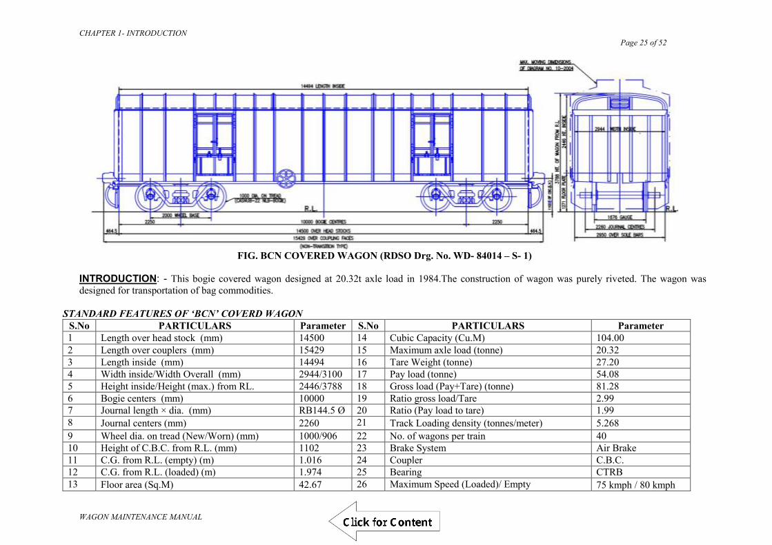
FIG. BCN COVERED WAGON (RDSO Drg. No. WD- 84014 – S- 1)
INTRODUCTION: - This bogie covered wagon designed at 20.32t axle load in 1984.The construction of wagon was purely riveted. The wagon was designed for transportation of bag commodities.
STANDARD FEATURES OF ‘BCN’ COVERD WAGON
S.No PARTICULARS Parameter S.No PARTICULARS Parameter 1 Length over head stock (mm) 14500 14 Cubic Capacity (Cu.M) 104.00 2 Length over couplers (mm) 15429 15 Maximum axle load (tonne) 20.32 3 Length inside (mm) 14494 16 Tare Weight (tonne) 27.20 4 Width inside/Width Overall (mm) 2944/3100 17 Pay load (tonne) 54.08 5 Height inside/Height (max.) from RL. 2446/3788 18 Gross load (Pay+Tare) (tonne) 81.28 6 Bogie centers (mm) 10000 19 Ratio gross load/Tare 2.99 7 Journal length × dia. (mm) RB144.5 Ø 20 Ratio (Pay load to tare) 1.99 8 Journal centers (mm) 2260 21 Track Loading density (tonnes/meter) 5.268 9 Wheel dia. on tread (New/Worn) (mm) 1000/906 22 No. of wagons per train 40 10 Height of C.B.C. from R.L. (mm) 1102 23 Brake System Air Brake 11 C.G. from R.L. (empty) (m) 1.016 24 Coupler C.B.C. 12 C.G. from R.L. (loaded) (m) 1.974 25 Bearing CTRB 13 Floor area (Sq.M) 42.67 26 Maximum Speed (Loaded)/ Empty 75 kmph / 80 kmph
Draft

CHAPTER 1- INTRODUCTION Page 26 of 52
WAGON MAINTENANCE MANUAL
FIG. BCNA COVERED WAGON (RDSO Drg. No. WD- 90030 – S- 51)
INTRODUCTION: - This wagon is an improved BCN wagon having reduced length and increase height by keeping volumetric capacity same and the wagon was fully welded construction.
STANDARD FEATURES OF ‘BCNA’ COVERD WAGON
S.No PARTICULARS Parameter S.No PARTICULARS Parameter 1 Length over head stock (mm) 13521 14 Cubic Capacity (Cu.M) 103.40 2 Length over couplers (mm) 14450 15 Maximum axle load (tonne) 20.32 3 Length inside (mm) 13515 16 Tare Weight (tonne) 24.55 4 Width inside/Width Overall (mm) 2944/3200 17 Pay load (tonne) 56.73 5 Height inside/Height (max.) from RL. 2677/4017 18 Gross load (Pay+Tare) (tonne) 81.28 6 Bogie centers (mm) 9500 19 Ratio gross load/Tare 3.31 7 Journal length × dia. (mm) RB144.5 Ø 20 Ratio (Pay load to tare) 2.31 8 Journal centers (mm) 2260 21 Track Loading density (tonnes/meter) 5.625 9 Wheel dia. on tread (New/Worn) (mm) 1000/906 22 No. of wagons per train 43 10 Height of C.B.C. from R.L. (mm) 1104 23 Brake System Air Brake 11 C.G. from R.L. (empty) (m) 1.2395 24 Coupler C.B.C. 12 C.G. from R.L. (loaded) (m) 1.9915 25 Bearing CTRB 13 Floor area (Sq.M) - 26 Maximum Speed (Loaded)/ Empty 75 kmph / 80 kmph
Draft

CHAPTER 1- INTRODUCTION Page 27 of 52
WAGON MAINTENANCE MANUAL
FIG. BCNAHS COVERED WAGON (RDSO Drg. No. WD- 90030 – S- 51)
INTRODUCTION: - This wagon is variant of BCNA wagon with high speed bogie CASNUB-22HS-BOGIE. The other parameters of this wagon are same as of BCNA wagon.
STANDARD FEATURES OF ‘BCNAHS’ COVERD WAGON
S.No PARTICULARS Parameter S.No PARTICULARS Parameter 1 Length over head stock (mm) 13521 14 Cubic Capacity (Cu.M) 103.40 2 Length over couplers (mm) 14450 15 Maximum axle load (tonne) 20.32 3 Length inside (mm) 13515 16 Tare Weight (tonne) 24.6 4 Width inside/Width Overall (mm) 2944/3200 17 Pay load (tonne) 56.68 5 Height inside/Height (max.) from RL. 2677/4017 18 Gross load (Pay+Tare) (tonne) 81.28 6 Bogie centers (mm) 9500 19 Ratio gross load/Tare 3.3 7 Journal length × dia. (mm) RB144.5 Ø 20 Ratio (Pay load to tare) 2.3 8 Journal centers (mm) 2260 21 Track Loading density (tonnes/meter) 5.625 9 Wheel dia. on tread (New/Worn) (mm) 1000/906 22 No. of wagons per train 43 10 Height of C.B.C. from R.L. (mm) 1104 23 Brake System Air Brake 11 C.G. from R.L. (empty) (m) 1.2395 24 Coupler C.B.C. 12 C.G. from R.L. (loaded) (m) 1.9915 25 Bearing CTRB 13 Floor area (Sq.M) - 26 Maximum Speed (Loaded)/ Empty 100 kmph / 100 kmph
Draft

CHAPTER 1- INTRODUCTION Page 28 of 52
WAGON MAINTENANCE MANUAL
FIG. BCNHL COVERED WAGON (RDSO Drg. No. WD- 06076 – S- 02)
INTRODUCTION: - This wagon fitted with twin pipe graduated release air brake system, high tensile non transition type CBC and cast steel bogie to
STR No. WD-17 CASNUB 22 HS Bogie 92 with latest amendment. STANDARD FEATURES OF BCNHL WAGON ‐DESIGN‐D S.No. PARTICULARS Parameter S.No. PARTICULARS Parameter 1 Length over Hd. Stock 10034 mm 11 Pay load 70.8t. 2 Length over buffer/couplers 10963 mm 12 Ratio pay load /tare 3.4 3 Length inside 10034 mm 13 Gross load 91.6 t. 4 Width inside/overall 3345/3450 mm 14 No. of wagons per rake 58 5 Height inside/from rail 3024/4305mm 15 Throughput per rake 4106 t. 6 Bogie centres 7153 mm 16 Loading density 8.35 t./m 7 Journal centres 2260mm 17 Cubic capacity 92.54 m³ 8 Wheel dia. On tread 1000mm 18 Speed (empty/ loaded) 100 Kmph 9 Nominal max. axle load 22.9 t. 19 Type of coupler CBC 10 Tare 20.8t. 20 Type of bearing CTRB
Draft

CHAPTER 1- INTRODUCTION Page 29 of 52
WAGON MAINTENANCE MANUAL
STANDARD FEATURES OF BCBFG WAGON (Food Grains) Drg. No.RSD-6337-052 S.No. PARTICULARS Parameter S.No. PARTICULARS Parameter 1 Length over Hd. Stock 11861mm 11 Pay load 60.84 t. 2 Length over buffer/couplers 12790 mm 12 Ratio pay load /tare 2.38 3 Length inside 11770 mm 13 Gross load 87.28 t. 4 Width inside/overall 3140/3250 mm 14 No. of wagons per rake 49 5 Max. Height from rail 4260 mm 15 Throughput per rake 2981 t. 6 Bogie centres 8661 mm 16 Loading density 6.82 t./m 7 Journal centres 2260 mm 17 Cubic capacity 81.76 m3 8 Wheel dia. On tread 1000 mm 18 Speed (empty/ loaded) E‐75 & L‐75 9 Nominal max. axle load 21.82 t. 19 Type of coupler CBC 10 Tare 26.44 t. 20 Type of bearing CTRB
Draft

CHAPTER 1- INTRODUCTION Page 30 of 52
WAGON MAINTENANCE MANUAL
STANDARD FEATURES OF BCFC WAGON S. No. PARTICULARS Fly Ash Cement S. No. PARTICULARS Fly Ash Cement
1 Length over Hd. Stock 9784mm 9784mm 11 Pay load 49 t. 67.3 t. 2 Length over buffer/couplers 10713 mm 10713 mm 12 Ratio pay load /tare 2.22 3.06 3 Length inside 10084.7 mm 10084.7 mm 13 Gross load 71 t. 89.3 t.
4 Width inside/overall 3128.7/3245 mm
3128.7/3245 mm 14 No. of wagons per rake 58 58
5 Height inside/from rail 4165 mm 4165 mm 15 Throughput per rake 2842 t. 3904 t. 6 Bogie centres 6684 mm 6684 mm 16 Loading density 6.62 t./m 8.335 t./m 7 Journal centres 2260 mm 2260 mm 17 Cubic capacity 72.8 m³ 72.8 m³ 8 Wheel dia. On tread 1000 mm 1000 mm 18 Speed (empty/ loaded) 65 Kmph 65 Kmph 9 Nominal max. axle load 17.75 t. 22.32 t. 19 Type of coupler CBC CBC 10 Tare 22 t. 22 t. 20 Type of bearing CTRB CTRB
Draft

CHAPTER 1- INTRODUCTION Page 31 of 52
WAGON MAINTENANCE MANUAL
FIG. BRN FLAT WAGON (RDSO Drg. No. WD- 84013 – S- 1)
INTRODUCTION: - This bogie rail wagon was designed in 1994. The design was improvement of earlier design of BRH wagon. The wagon Design is with air brake and welded construction.
STANDARD FEATURES OF ‘BRN’ FLAT WAGON
S.No PARTICULARS Parameter S.No PARTICULARS Parameter 1 Length over head stock (mm) 13716 14 Maximum axle load (tonne) 20.32 2 Length over couplers (mm) 14645 15 Tare Weight (tonne) 24.393 3 Length inside (mm) 13716 16 Pay load (tonne) 56.887 4 Width inside/Width Overall (mm) 2845 17 Gross load (Pay+Tare) (tonne) 81.28 5 Height inside/Height (max.) from RL. ---/ 2544 18 Ratio gross load/Tare 3.33 6 Bogie centers (mm) 9144 19 Ratio (Pay load to tare) 2.33 7 Journal length × dia. (mm) RB144.5 Ø 20 Track Loading density (tonnes/meter) 5.55 8 Journal centers (mm) 2260 21 No. of wagons per train 42 9 Wheel dia. on tread (New/Worn) (mm) 1000/906 22 Brake System Air Brake 10 Height of C.B.C. from R.L. (mm) 1105 23 Coupler C.B.C. 11 C.G. from R.L. (empty) (m) - 24 Bearing CTRB 12 C.G. from R.L. (loaded) (m) - 25 Maximum Speed (Loaded)/ Empty 75 kmph / 80 kmph 13 Floor area (Sq.M) -
Draft

CHAPTER 1- INTRODUCTION Page 32 of 52
WAGON MAINTENANCE MANUAL
FIG. BRNA FLAT WAGON (RDSO Drg. No. WD- 92004 – S- 02)
INTRODUCTION: - This bogie rail wagon was designed by improvement of BRN wagon in 1992. The design was riveted cum welded construction. It is higher pay to tare ratio as compared to BRN wagon.
STANDARD FEATURES OF ‘BRNA’ FLAT WAGON
S.No PARTICULARS Parameter S.No PARTICULARS Parameter 1 Length over head stock (mm) 13716 14 Maximum axle load (tonne) 20.32 2 Length over couplers (mm) 14645 15 Tare Weight (tonne) 23.543 3 Length inside (mm) 1 3 7 1 6 16 Pay load (tonne) 57.737 4 Width inside/Width Overall (mm) 2845 17 Gross load (Pay+Tare) (tonne) 81.28 5 Height inside/Height (max.) from RL. (mm) 2544 18 Ratio gross load/Tare 3.452 6 Bogie centers (mm) 9144 19 Ratio (Pay load to tare) 2.452 7 Journal length × dia. (mm) RB144.5 Ø 20 Track Loading density (tonnes/meter) 5.55 8 Journal centers (mm) 2260 21 No. of wagons per train 42 9 Wheel dia. on tread (New/Worn) (mm) 1000/906 22 Brake System Air Brake 10 Height of C.B.C. from R.L. (mm) 1105 23 Coupler C.B.C. 11 C.G. from R.L. (empty) (m) - 24 Bearing CTRB 12 C.G. from R.L. (loaded) (m) - 25 Maximum Speed (Loaded)/ Empty 75 kmph / 80 kmph 13 Floor area (Sq.M) -
Draft

CHAPTER 1- INTRODUCTION Page 33 of 52
WAGON MAINTENANCE MANUAL
STANDARD FEATURES OF BRSTN WAGON S. No. PARTICULARS Parameter S. No. PARTICULARS Parameter
1 Length over Hd. Stock 13716mm 11 Pay load 56.27 t. 2 Length over buffer/couplers 14998 mm 12 Ratio pay load /tare 2.25 3 Length inside 13716 mm 13 Gross load 81.28 t. 4 Width inside/overall 3200mm 14 No. of wagons per rake 41 5 Height inside/from rail 1264 mm 15 Throughput per rake -- 6 Bogie centres 9144 mm 16 Loading density 5.419 t/m. 7 Journal centres 2260 mm 17 Cubic capacity FLAT WAGON 8 Wheel dia. On tread 1000 mm 18 Speed (empty/ loaded) 80/75 Kmph 9 Nominal max. axle load 20.32 t. 19 Type of coupler CBC 10 Tare 25.01 t. 20 Type of bearing CTRB
Draft

CHAPTER 1- INTRODUCTION Page 34 of 52
WAGON MAINTENANCE MANUAL
STANDARD FEATURES OF BRHNEHS WAGON (WD-04 004-S-52) S. No. PARTICULARS Parameter S. No. PARTICULARS Parameter
1 Length over Hd. Stock 13716mm 11 Pay load 58.68 t.
2 Length over buffer/couplers 14986/14998 mm 12 Ratio pay load /tare 2.596
3 Length inside 12716mm 13 Gross load 81.28 t.
4 Width inside/overall 2845/3049 mm 14 No. of wagons per rake 41
5 Height inside/from rail 1264 mm/2008mm 15 Throughput per rake 2406 t.
6 Bogie centres 9144 mm 16 Loading density 5.419 t/m
7 Journal centres 2260 mm 17 Cubic capacity Flat Wagon
8 Wheel dia. On tread 1000 mm 18 Speed (empty/ loaded) 65/65 kmph
9 Nominal max. axle load 20.32 t. 19 Type of coupler Transition type CBC
10 Tare 22.6 t. 20 Type of bearing CTRB (6X11) E‐Class
Draft

CHAPTER 1- INTRODUCTION Page 35 of 52
WAGON MAINTENANCE MANUAL
STANDARD FEATURES OF BRN WAGON ‐22.9 t S.No. PARTICULARS Parameter S.No. PARTICULARS Parameter 1 Length over Hd. Stock 13716mm 11 Pay load 68.292 t. 2 Length over buffer/couplers 14645 mm 12 Ratio pay load /tare 2.93 3 Length inside 13716 mm 13 Gross load 91.6 t. 4 Width inside/overall 2930 mm inside 14 No. of wagons per rake 42 5 Height inside/from rail 2555mm from R.L. 15 Throughput per rake 2868 t 6 Bogie centres 9144 mm 16 Loading density 6.25 t/m. 7 Journal centres 2260 mm 17 Cubic capacity FLAT WAGON 8 Wheel dia. On tread 1000 mm 18 Speed (empty/ loaded) 65/65 Kmph 9 Nominal max. axle load 22.9 t. 19 Type of coupler CBC 10 Tare 23.3 t. 20 Type of bearing CTRB
Draft

CHAPTER 1- INTRODUCTION Page 36 of 52
WAGON MAINTENANCE MANUAL
STANDARD FEATURES OF BOMN WAGON S. No. PARTICULARS Parameter S. No. PARTICULARS Parameter
1 Length over Hd. Stock 18460mm 11 Pay load 35.850 t. 2 Length over buffer/couplers 19742 mm 12 Ratio pay load /tare 1.2 3 Length inside 18460 mm 13 Gross load 65.626 t. 4 Width inside/overall 3100/3200 mm 14 No. of wagons per rake 31 5 Height inside/from rail 1275 mm 15 Throughput per rake - 6 Bogie centres 13890 mm 16 Loading density 3.324 t/m. 7 Journal centres 2260 mm 17 Cubic capacity FLAT WAGON 8 Wheel dia. On tread 1000 mm 18 Speed (empty/ loaded) 80/75 Kmph 9 Nominal max. axle load 16.4 t. 19 Type of coupler CBC
10 Tare 29.776 t. 20 Type of bearing CTRB
Draft

CHAPTER 1- INTRODUCTION Page 37 of 52
WAGON MAINTENANCE MANUAL
FIG. BFNS FLAT WAGON (RDSO Drg. No. WD- 98057 – S- 02)
INTRODUCTION: - This bogie flat steel wagon is the one of the first wagon designed in Indian Railways to carry point load in 1998. The wagon was designed specially for transportation of hot rolled/cold rolled coils, plates, sheets and billets etc.
STANDARD FEATURES OF ‘BFNS’ FLAT WAGON
S.No PARTICULARS Parameter S.No PARTICULARS Parameter 1 Length over head stock (mm) 13716 14 Maximum axle load (tonne) 20.32 2 Length over couplers (mm) 14645 15 Tare Weight (tonne) 26.71 3 Length inside (mm) 13716 16 Pay load (tonne) 54.57 4 Width inside/Width Overall (mm) 2845 17 Gross load (Pay+Tare) (tonne) 81.28 5 Height inside/Height (max.) from RL. --- 18 Ratio gross load/Tare 3.043 6 Bogie centers (mm) 9144 19 Ratio (Pay load to tare) 2.043 7 Journal length × dia. (mm) RB144.5 Ø 20 Track Loading density (tonnes/meter) 5.55 8 Journal centers (mm) 2260 21 No. of wagons per train 42 9 Wheel dia. on tread (New/Worn) (mm) 1000/906 22 Brake System Air Brake 10 Height of C.B.C. from R.L. (mm) 1105 23 Coupler C.B.C. 11 C.G. from R.L. (empty) (m) - 24 Bearing CTRB 12 C.G. from R.L. (loaded) (m) - 25 Maximum Speed (Loaded)/ Empty 100/100 kmph (75/80Kmph, in case of
speed certificate conditions not meeting) 13 Floor area (Sq.M) -
Draft

CHAPTER 1- INTRODUCTION Page 38 of 52
WAGON MAINTENANCE MANUAL
FIG. HOPPER TYPE “BOBR”WAGON (RDSO Drg. No. WD – 86013 – S - 51)
INTRODUCTION: - This wagon is designed for transportation of coal with bottom discharge facility for faster evacuation.
STANDARD FEATURES OF ‘BOBR’ HOPPER WAGON
S.No PARTICULARS Parameter S.No PARTICULARS Parameter 1 Length over head stock (mm) 10671 14 Cubic Capacity (Cu.M) 57.2 2 Length over couplers (mm) 11600 15 Maximum axle load (tonne) 20.32 3 Length inside (mm) 8732 16 Tare Weight (tonne) 26.40 4 Width inside/Width Overall (mm) 3340/3500 17 Pay load (tonne) 54.88 5 Height inside/Height (max.) from RL. 2461/3735 18 Gross load (Pay+Tare) (tonne) 81.28 6 Bogie centers (mm) 7571 19 Ratio gross load/Tare 3.08 7 Journal length × dia. (mm) RB144.5Ø 20 Ratio (Pay load to tare) 2.08 8 Journal centers (mm) 2260 21 Track Loading density (tonnes/meter) 7.00 9 Wheel dia. on tread (New/Worn) (mm) 1000/906 22 No. of wagons per train 53 10 Height of C.B.C. from R.L. (mm) 1105 23 Brake System Air brake 11 C.G. from R.L. (empty) (m) 1.13 24 Coupler C.B.C. 12 C.G. from R.L. (loaded) (m) 2.06 25 Bearing CTRB 13 Floor area (Sq.M) --- 26 Maximum Speed (Loaded)/ Empty 80 kmph / 80 kmph
Draft

CHAPTER 1- INTRODUCTION Page 39 of 52
WAGON MAINTENANCE MANUAL
FIG. HOPPER TYPE BOBRN WAGON (RDSO Drg. No. WD – 91071 – S - 51)
INTRODUCTION: - This wagon is a variant BOBR with air brake and has two doors.
STANDARD FEATURES OF ‘BOBRN’ HOPPER WAGON
S.No PARTICULARS Parameter S.No PARTICULARS Parameter 1 Length over head stock (mm) 9671 14 Cubic Capacity (Cu.M) 56.78 2 Length over couplers (mm) 10600 15 Maximum axle load (tonne) 20.32 3 Length inside (mm) 9327 16 Tare Weight (tonne) 25.61 4 Width inside/Width Overall (mm) 3340/3500 17 Pay load (tonne) 55.67 5 Height inside/Height (max.) from RL. 2466/3735 18 Gross load (Pay+Tare) (tonne) 81.28 6 Bogie centers (mm) 6790 19 Ratio gross load/Tare 3.174 7 Journal length × dia. (mm) RB144.5Ø 20 Ratio (Pay load to tare) 2.174 8 Journal centers (mm) 2260 21 Track Loading density (tonnes/meter) 7.67 9 Wheel dia. on tread (New/Worn) (mm) 1000/906 22 No. of wagons per train 58 10 Height of C.B.C. from R.L. (mm) 1105 23 Brake System Air brake 11 C.G. from R.L. (empty) (m) 1.12 24 Coupler C.B.C. 12 C.G. from R.L. (loaded) (m) 2.241 25 Bearing CTRB 13 Floor area (Sq.M) --- 26 Maximum Speed (Loaded)/ Empty 70 kmph / 75 kmph
Draft

CHAPTER 1- INTRODUCTION Page 40 of 52
WAGON MAINTENANCE MANUAL
STANDARD FEATURES OF BOBRNHS WAGON (20.32 t) WD‐91071‐S‐51(Alt-10)
S.No. Particulars Parameter S. No. Particulars Parameter 1 Length over Hd. Stock 9671mm 11 Pay load 55.67 t. 2 Length over buffer/couplers 10600 mm 12 Ratio pay load /tare 2.17 3 Length inside 9327 mm 13 Gross load 81.28 t. 4 Width inside/overall 3340/3500 mm 14 No. of wagons per rake 58 5 Height inside/from rail 2466/3735 mm 15 Throughput per rake 3228.86 t. 6 Bogie centres 6790 mm 16 Loading density 7.67 t/m. 7 Journal centres 2260 mm 17 Cubic capacity 56.78 m3 8 Wheel dia. On tread 1000 mm 18 Speed (empty/ loaded) 100/100 Kmph 9 Nominal max. axle load 20.32 t. 19 Type of coupler CBC 10 Tare 25.61 t. 20 Type of bearing CTRB
Draft

CHAPTER 1- INTRODUCTION Page 41 of 52
WAGON MAINTENANCE MANUAL
STANDARD FEATURES OF BOBRNHSM1 WAGON(22.32 t) (CC+6t+2t) S.No. PARTICULARS Parameter S.No. PARTICULARS Parameter 1 Length over Hd. Stock 9671mm 11 Pay load 63.67 t. 2 Length over buffer/couplers 10600 mm 12 Ratio pay load /tare 2.48 3 Length inside 9327 mm 13 Gross load 89.28 t. 4 Width inside/overall 3340/3500 mm 14 No. of wagons per rake 58 5 Height inside/from rail 2466/3735 mm 15 Throughput per rake 3692.86 t 6 Bogie centres 6790 mm 16 Loading density 8.42 t/m 7 Journal centres 2260 mm 17 Cubic capacity 56.78 m3 8 Wheel dia. On tread 1000 mm 18 Speed (empty/ loaded) 65/60 Kmph 9 Nominal max. axle load 22.32 t. 19 Type of coupler CBC 10 Tare 25.61 t. 20 Type of bearing CTRB STANDARD FEATURES OF BOBRNEL WAGON (25.0 t) (Iron Ore) S.No. PARTICULARS Parameter S.No. PARTICULARS Parameter 1 Length over Hd. Stock 9671mm 11 Pay load 74.39 t. 2 Length over buffer/couplers 10600 mm 12 Ratio pay load /tare 2.9 3 Length inside 9327 mm 13 Gross load 100.00 t. 4 Width inside/overall 3340/3500 mm 14 No. of wagons per rake 58 5 Height inside/from rail 2466/3735 mm 15 Throughput per rake 4314.62 t. 6 Bogie centres 6790 mm 16 Loading density 9.43 t/m.
7 Journal centres 2260 mm
17 Cubic capacity (Marking has been done for loading of Iron Ore upto 1725 mm. Height from top of centre sill)
8 Wheel dia. On tread 1000 mm 18 Speed (empty/ loaded) 60+5/45+5 (Provisional) Kmph
9 Nominal max. axle load 25.00 t. 19 Type of coupler -- 10 Tare 25.61 t. 20 Type of bearing --
Draft

CHAPTER 1- INTRODUCTION Page 42 of 52
WAGON MAINTENANCE MANUAL
STANDARD FEATURES OF BOBRNM1 WAGON (22.32t) (CC+6t+2t) S.No. PARTICULARS Parameter S.No. PARTICULARS Parameter 1 Length over Hd. Stock 9671mm 11 Pay load 63.67 t. 2 Length over buffer/couplers 10600 mm 12 Ratio pay load /tare 2.48 3 Length inside 9327 mm 13 Gross load 89.28 t.
4 Width inside/overall 3340/3500 mm 14 No. of wagons per rake 58
5 Height inside/from rail 2466/3735 mm 15 Throughput per rake 3692.86 t 6 Bogie centres 6790 mm 16 Loading density 8.42 t/m 7 Journal centres 2260 mm 17 Cubic capacity 56.78 m3 8 Wheel dia. On tread 1000 mm 18 Speed (empty/ loaded) 80/70 Kmph 9 Nominal max. axle load 22.32 t. 19 Type of coupler CBC 10 Tare 25.61 t. 20 Type of bearing CTRB STANDARD FEATURES OF BOBRN WAGON (22.32t) (CC+6t+2t) S.No. PARTICULARS Parameter S.No. PARTICULARS Parameter 1 Length over Hd. Stock 9671mm 11 Pay load 63.67 t. 2 Length over buffer/couplers 10600 mm 12 Ratio pay load /tare 2.48 3 Length inside 9327 mm 13 Gross load 89.28 t 4 Width inside/overall 3340/3500 mm 14 No. of wagons per rake 58 5 Height inside/from rail 2466/3735 mm 15 Throughput per rake 3692.86 t. 6 Bogie centres 6790 mm 16 Loading density 8.42 t/m 7 Journal centres 2260 mm 17 Cubic capacity 56.78 m3 8 Wheel dia. On tread 1000 mm 18 Speed (empty/ loaded) 65/60 Kmph 9 Nominal max. axle load 22.32 t. 19 Type of coupler CBC 10 Tare 25.61 t. 20 Type of bearing CTRB
Draft

CHAPTER 1- INTRODUCTION Page 43 of 52
WAGON MAINTENANCE MANUAL
RL
STANDARD FEATURES OF BOBYN/ BOBYNHS WAGON (WD-96081-S-02) (Alt-8) S.No. PARTICULARS Parameter S.No. PARTICULARS Parameter 1 Length over Hd. Stock 10718mm 11 Pay load 66.4 t. 2 Length over buffer/couplers 11647 mm 12 Ratio pay load /tare 2.6 3 Length inside 9000 mm 13 Gross load 91.6 t. 4 Width inside/overall 2863/3189 mm 14 No. of wagons per rake 50 (in 585 M) 5 Height inside/from rail 2018/3287 mm 15 Throughput per rake 3320 t. 6 Bogie centres 7470 mm 16 Loading density 7.86 t/m 7 Journal centres 2260 mm 17 Cubic capacity 46.1 m3 8 Wheel dia. On tread 1000 mm 18 Speed (empty/ loaded) -- 9 Nominal max. axle load 22.9 t. 19 Type of coupler NT. CBC 10 Tare 25.2 t. 20 Type of bearing CTRB (6X11) EClass
Draft

CHAPTER 1- INTRODUCTION Page 44 of 52
WAGON MAINTENANCE MANUAL
STANDARD FEATURES OF ‘BOBYN 22.9’ WAGON –(22.9 WD-09090-S-02) (Design B) S.No. PARTICULARS Parameter S.No. PARTICULARS Parameter 1 Length over Hd. Stock 10718mm 11 Pay load 66.3 t. 2 Length over buffer/couplers 11647 mm 12 Ratio pay load /tare 2.6 3 Length inside 9000 mm 13 Gross load 91.6 t. 4 Width inside/overall 2863/3189 mm 14 No. of wagons per rake 50 (in 585 M) 5 Height inside/from rail 2024/3293 mm 15 Throughput per rake 3315 t. 6 Bogie centres 7470 mm 16 Loading density 7.86 t/m 7 Journal centres 2260 mm 17 Cubic capacity 46.16 m3 8 Wheel dia. On tread 1000 mm 18 Speed (empty/ loaded) 65/65 kmph. 9 Nominal max. axle load 22.9 t. 19 Type of coupler NT. CBC 10 Tare 25.3 t. 20 Type of bearing CTRB (6X11) EClass
Draft

CHAPTER 1- INTRODUCTION Page 45 of 52
WAGON MAINTENANCE MANUAL
STANDARD FEATURES OF BOBSN WAGON (22.9 t.) Drg. No. WD-94038-S-02 S.No. PARTICULARS Parameter S.No. PARTICULARS Parameter 1 Length over Hd. Stock 10668mm 11 Pay load 61.6 t. 2 Length over buffer/couplers 11597mm 12 Ratio pay load /tare 2.05
3 Length inside 9296mm 13 Gross load 91.6 t.
4 Width inside/overall 2743/3020mm 14 No. of wagons per rake - 5 Height inside/from rail 2042/3301mm 15 Throughput per rake -- 6 Bogie centres 7112 mm 16 Loading density 7.9 t/m. 7 Journal centres 2260 mm 17 Cubic capacity 34.0m3 8 Wheel dia. On tread 1000 mm 18 Speed (empty/ loaded) -- 9 Nominal max. axle load 22.9 T. 19 Type of coupler CBC 10 Tare 30.0 t. 20 Type of bearing CTRB STANDARD FEATURES OF BOBSNM1 WAGON (25.0 t.) Drg. No. WD-94038-S-02 S.No. PARTICULARS Parameter S.No. PARTICULARS Parameter 1 Length over Hd. Stock 10668mm 11 Pay load 70.0 t. 2 Length over buffer/couplers 11597 mm 12 Ratio pay load /tare 2.33 3 Length inside 9296mm 13 Gross load 100.00 t. 4 Width inside/overall 2743/3020mm 14 No. of wagons per rake - 5 Height inside/from rail 2042/3301mm 15 Throughput per rake -- 6 Bogie centres 7112 mm 16 Loading density 8.62 t/m. 7 Journal centres 2260 mm 17 Cubic capacity 34.0m3 8 Wheel dia. On tread 1000 mm 18 Speed (empty/ loaded) 55+5/45+5 Kmph 9 Nominal max. axle load 25.00t. 19 Type of coupler CBC 10 Tare 30.0 t. 20 Type of bearing CTRB
Draft

CHAPTER 1- INTRODUCTION Page 46 of 52
WAGON MAINTENANCE MANUAL
FIG. BTPN TANK WAGON (RDSO Drg. No. WD – 86081 – S - 51)
INTRODUCTION: - This wagon has been designed for transportation of petroleum products i.e. kerosene, petrol, diesel and naphtha.
STANDARD FEATURES OF „BTPN’ TANK WAGON
S.No PARTICULARS Parameter S.No PARTICULARS Parameter 1 Length over head stock (mm) 11491 14 Cubic Capacity (Cu.M) 70.40 2 Length over couplers (mm) 12420 15 Maximum axle load (tonne) 20.32 3 Length of barrel inside (mm) 11434 16 Tare Weight (tonne) 27.00 4 Dia. inside (barrel) (mm) 2850 17 Pay load (tonne) 54.28 5 Overall Height from R.L. (mm). 4265 18 Gross load (Pay+Tare) (tonne) 81.28 6 Bogie centers (mm) 8391 19 Ratio gross load/Tare 3.01 7 Journal length × dia. (mm) 277.8x144.5 20 Ratio (Pay load to tare) 2.01 8 Journal centers (mm) 2260 21 Track Loading density (tonnes/meter) 6.54 9 Wheel dia. on tread (New/Worn) (mm) 1000/906 22 No. of wagons per train 47 10 Height of C.B.C. from R.L. (mm) 1105 23 Brake System Air brake 11 C.G. from R.L. (empty) (m) 1.43 24 Coupler C.B.C. 12 C.G. from R.L. (loaded) (m) 2.23 25 Bearing CTRB 13 Max. Volumetric carrying capacity (L) --- 26 Maximum Speed (Loaded)/ Empty 75 kmph / 80 kmph
Draft

CHAPTER 1- INTRODUCTION Page 47 of 52
WAGON MAINTENANCE MANUAL
FIG. BTPGLN TANK WAGON (RDSO Drg. No. WD – 93047 – S - 51)
INTRODUCTION: - This wagon is a variant of BTPGL with air brake and casnub trolley.
STANDARD FEATURES OF ‘BTPGLN’ TANK WAGON
S.No PARTICULARS Parameter S.No PARTICULARS Parameter 1 Length over head stock (mm) 18000 14 Cubic Capacity (Cu.M) 79.48 2 Length over couplers (mm) 18929 15 Maximum axle load (tonne) 19.8 3 Length of barrel inside (mm) 17960 16 Tare Weight (tonne) 41.6 4 Dia. inside (barrel) (mm) 2400 17 Pay load (tonne) 37.6 5 Overall Height from R.L. (mm). 4285 18 Gross load (Pay+Tare) (tonne) 79.2 6 Bogie centers (mm) 12970 19 Ratio gross load/Tare 1.903 7 Journal length × dia. (mm) RB 144.5 Ø 20 Ratio (Pay load to tare) 0.903 8 Journal centers (mm) 2260 21 Track Loading density (tonnes/meter) 4.184 9 Wheel dia. on tread (New/Worn) (mm) 1000/906 22 No. of wagons per train 31 10 Height of C.B.C. from R.L. (mm) 1105 23 Brake System Air brake 11 C.G. from R.L. (empty) (m) 1.6 24 Coupler C.B.C. 12 C.G. from R.L. (loaded) (m) 2.03 25 Bearing CTRB 13 Max. Volumetric carrying capacity (L) --- 26 Maximum Speed (Loaded)/ Empty 75 kmph / 80 kmph
Draft

CHAPTER 1- INTRODUCTION Page 48 of 52
WAGON MAINTENANCE MANUAL
STANDARD FEATURES OF BTFLN WAGON (Pole Tank Wagon) (* in 636 meters Loop length without safety wagon)
S. No. PARTICULARS Parameter S. No. PARTICULARS Parameter
1 Length over Hd. Stock 11491mm 11 Pay load 57.95 2 Length over buffer/couplers 12420 mm 12 Ratio pay load /tare 2.48 3 Length inside 11522 (inside Barrel length.) 13 Gross load 81.28 t. 4 Width inside/overall 2950(inside Dia. of Barrel) 14 No. of wagons per rake 51 * 5 Height inside/from rail 4358 (over all Ht.) 15 Throughput per rake 2955.45 t. 6 Bogie centres 8391mm 16 Loading density 6.54 t./m 7 Journal centres 2260 mm 17 Cubic capacity 76 m³ 8 Wheel dia. On tread 1000 mm 18 Speed (empty/ loaded) -- 9 Nominal max. axle load 20.32 t. 19 Type of coupler CBC
10 Tare 23.33 t. 20 Type of bearing CTRB
Draft

CHAPTER 1- INTRODUCTION Page 49 of 52
WAGON MAINTENANCE MANUAL
FIG. BVZI BRAKE VAN (RDSO Drg. No. WD- 00039/ S- 02)
INTRODUCTION: - This 8-wheeled brake van was designed with ICF bogie to achieve comfort level (Ride Index) equivalent to loco criteria for goods guard and capable of running 100 kmph. The brake van was 5 meter longer than BVZC brake van.
STANDARD FEATURES OF ‘BVZI’ BRAKE VAN
S.No PARTICULARS Parameter S.No PARTICULARS Parameter 1 Length over head stock (mm) 13540 14 Cubic Capacity (Cu.M) ---- 2 Length over couplers (mm) 14469 15 Maximum axle load (tonne) 5.87520.32 3 Length inside (mm) --- 16 Tare Weight (tonne) 23.524.6 4 Width inside/Width Overall (mm) ------/3200 17 Pay load (tonne) -----56.68 5 Height inside/Height (max.) from RL. 2448/3894 18 Gross load (Pay+Tare) (tonne) 23.5+….81.28 6 Bogie centers (mm) 9026 19 Ratio gross load/Tare 1.003.3 7 Journal length × dia. (mm) ---- 20 Ratio (Pay load to tare) ---- 8 Journal centers (mm) ---- 21 Track Loading density (tonnes/meter) 1.6245.625 9 Wheel dia. on tread (New/Worn) (mm) 915/813 22 No. of wagons per train ----- 10 Height of C.B.C. from R.L. (mm) 1105 23 Brake System Air Brake 11 C.G. from R.L. (empty) (m) 0.981 24 Coupler C.B.C. 12 C.G. from R.L. (loaded) (m) 0.981 25 Bearing CTRB 13 Floor area (Sq.M) ---- 26 Maximum Speed (Loaded)/ Empty 100 kmph / 100 kmph
Draft

CHAPTER 1- INTRODUCTION Page 50 of 52
WAGON MAINTENANCE MANUAL
FIG. BLLA CONTAINER WAGON (RDSO Drg. No. 45 – A – 2001 – S/02)
INTRODUCTION: - Bogie Low Platform Longer Container flat (BLL) wagons has been designed jointly by RDSO & RITES for transportation of 22’ 24’ & 45’ containers along with 20’ & 40’ long ISO containers at an operating speed of 100 kmph. Lower height of under frame floor from R.L. has been achieved with introduction of hybrid design of bogie frame, bolster and use of smaller diameter wheel in LCCF 20(C) Bogie. BLLA (A-Car) wagons are placed at extreme end in formation of one unit of 5- cars (with 3 BLLB wagons in middle). Outer end of BLLA wagons are fitted with standard AAR-E/F TYPE Center Buffer Coupler (C.B.C.) and inner ends are fitted with Slackless Draw Bar (S.D.B.). Wagons are fitted with automatic twist locks to secure containers. STANDARD FEATURES OF ‘BLLA’ CONTAINER WAGON
S.No PARTICULARS Parameter S.No PARTICULARS Parameter 1 Length over head stock (mm) 15220 14 Cubic Capacity (Cu.M) ---- 2 Length over couplers (mm) 16161 15 Maximum axle load (tonne) 20.32 3 Length inside (mm) --- 16 Tare Weight (tonne) 19.8 4 Width over Headstock/Width over Bolster (mm) 2100/2200 17 Pay load (tonne) 61 5 Height inside/Height (max.) from RL. 1008 18 Gross load (Pay+Tare) (tonne) 80.8 6 Bogie centers (mm) 10700 19 Ratio gross load/Tare 4.08 7 Journal length × dia. (mm) 144x278 20 Ratio (Pay load to tare) 3.08 8 Journal centers (mm) 2260 21 Track Loading density (tonnes/meter) 5 9 Wheel dia. on tread (New/Worn) (mm) 840/780 22 No. of wagons per train of 45 wagons 16 10 Height of C.B.C/SDB from R.L. (mm) 1105/845 23 Brake System Air Brake 11 C.G. from R.L. (empty) (m) 0.604 24 Coupler C.B.C./S.D.B 12 C.G. from R.L. (loaded) (m) 1.998 25 Bearing CTRB 13 Floor area (Sq.M) ---- 26 Maximum Speed (Loaded)/ Empty 100 kmph / 100 kmph
Draft

CHAPTER 1- INTRODUCTION Page 51 of 52
WAGON MAINTENANCE MANUAL
FIG. BLLB CONTAINER WAGON (RDSO Drg. No. 45 – B – 2001 – S/02)
INTRODUCTION: - Bogie Low Platform Longer Container flat (BLL) wagons has been designed jointly by RDSO & RITES for transportation of 22’ 24’ & 45’ containers along with 20’ & 40’ long ISO containers at an operating speed of 100kmph. Lower height of under frame floor from R.L. has been achieved with introduction of hybrid design of bogie frame, bolster and use of smaller diameter wheel in LCCF 20( C) Bogie. BLLB (B-Car) wagons are placed in middle, in one unit of 5- cars (with outer A-Cars). Both ends of BLLB wagons are fitted with Slack less Draw Bar (S.D.B.). Wagons are fitted with automatic twist locks to secure containers. STANDARD FEATURES OF ‘BLLB’ CONTAINER WAGON
S.No PARTICULARS Parameter S.No PARTICULARS Parameter 1 Length over head stock (mm) 13810 14 Cubic Capacity (Cu.M) ---- 2 Length over couplers (mm) 14763 15 Maximum axle load (tonne) 20.32 3 Length inside (mm) --- 16 Tare Weight (tonne) 19 4 Width over Headstock/Width over Bolster (mm) 2100/2200 17 Pay load (tonne) 61 5 Height inside/Height (max.) from RL. 1008 18 Gross load (Pay+Tare) (tonne) 80 6 Bogie centers (mm) 9810 19 Ratio gross load/Tare 4.21 7 Journal length × dia. (mm) 144x278 20 Ratio (Pay load to tare) 3.21 8 Journal centers (mm) 2260 21 Track Loading density (tonnes/meter) 5.42 9 Wheel dia. on tread (New/Worn) (mm) 840/780 22 No. of wagons per train of 45 wagons 24 10 Height of S.D.B. from R.L. (mm) 845 23 Brake System Air Brake 11 C.G. from R.L. (empty) (m) 0.603 24 Coupler S.D.B 12 C.G. from R.L. (loaded) (m) 2.011 25 Bearing CTRB 13 Floor area (Sq.M) ---- 26 Maximum Speed (Loaded)/ Empty 100 kmph / 100 kmph
Draft

CHAPTER 1- INTRODUCTION Page 52 of 52
WAGON MAINTENANCE MANUAL
FIG. BLCA CONTAINER WAGON (RDSO Drg. No. CONTR – 9405 – S/2)
INTRODUCTION: - Bogie Low Platform Container flat (BLC) wagons has been designed for transportation of 20’ & 40’ long ISO containers at an operating speed of 100kmph.Lower height of under frame( floor) from R.L. has been achieved with introduction of hybrid design of bogie frame, bolster and use of smaller diameter wheel in LCCF 20( C) Bogie. BLCA (A-Car) wagons are placed at extreme ends in formation of one unit of 5- cars (with 3 BLCB wagons in middle). Outer end of BLCA wagons are fitted with standard AAR-E/F TYPE Center Buffer Coupler (C.B.C.) and inner ends are fitted with Slack less Draw Bar (S.D.B.). Wagons are fitted with automatic twist locks to secure containers.
STANDARD FEATURES OF ‘BLCA’ CONTAINER WAGON S.No PARTICULARS Parameter S.No PARTICULARS Parameter 1 Length over head stock (mm) 13625 14 Cubic Capacity (Cu.M) ---- 2 Length over couplers (mm) 14566 15 Maximum axle load (tonne) 20.32 3 Length inside (mm) --- 16 Tare Weight (tonne) 19.1 4 Width over Headstock/Width over Bolster (mm) 2100/2200 17 Pay load (tonne) 61 5 Height inside/Height (max.) from RL. 1269/1009 18 Gross load (Pay+Tare) (tonne) 80.1 6 Bogie centers (mm) 9675 19 Ratio gross load/Tare 4.21 7 Journal length × dia. (mm) 144x278 20 Ratio (Pay load to tare) 3.194 8 Journal centers (mm) 2260 21 Track Loading density (tonnes/meter) 5.5 9 Wheel dia. on tread (New/Worn) (mm) 840/780 22 No. of wagons per train of 45 wagons 18 10 Height of C.B.C./S.D.B. from R.L. (mm) 1105/845 23 Brake System Air Brake 11 C.G. from R.L. (empty) (m) 0.551 24 Coupler C.B.C/S.D.B 12 C.G. from R.L. (loaded) (m) 1.993 25 Bearing CTRB 13 Floor area (Sq.M) ---- 26 Maximum Speed (Loaded)/ Empty 100 kmph / 100 kmph
Draft
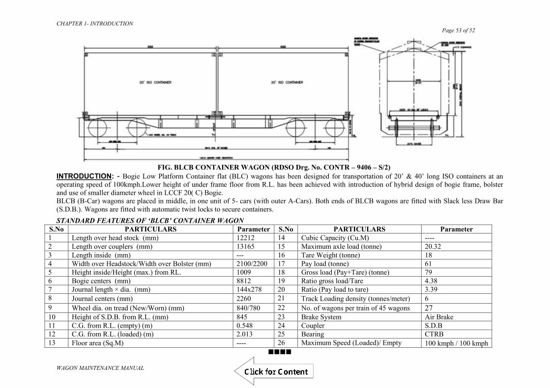
CHAPTER 1- INTRODUCTION Page 53 of 52
WAGON MAINTENANCE MANUAL
FIG. BLCB CONTAINER WAGON (RDSO Drg. No. CONTR – 9406 – S/2)
INTRODUCTION: - Bogie Low Platform Container flat (BLC) wagons has been designed for transportation of 20’ & 40’ long ISO containers at an operating speed of 100kmph.Lower height of under frame floor from R.L. has been achieved with introduction of hybrid design of bogie frame, bolster and use of smaller diameter wheel in LCCF 20( C) Bogie. BLCB (B-Car) wagons are placed in middle, in one unit of 5- cars (with outer A-Cars). Both ends of BLCB wagons are fitted with Slack less Draw Bar (S.D.B.). Wagons are fitted with automatic twist locks to secure containers.
STANDARD FEATURES OF ‘BLCB’ CONTAINER WAGON S.No PARTICULARS Parameter S.No PARTICULARS Parameter 1 Length over head stock (mm) 12212 14 Cubic Capacity (Cu.M) ---- 2 Length over couplers (mm) 13165 15 Maximum axle load (tonne) 20.32 3 Length inside (mm) --- 16 Tare Weight (tonne) 18 4 Width over Headstock/Width over Bolster (mm) 2100/2200 17 Pay load (tonne) 61 5 Height inside/Height (max.) from RL. 1009 18 Gross load (Pay+Tare) (tonne) 79 6 Bogie centers (mm) 8812 19 Ratio gross load/Tare 4.38 7 Journal length × dia. (mm) 144x278 20 Ratio (Pay load to tare) 3.39 8 Journal centers (mm) 2260 21 Track Loading density (tonnes/meter) 6 9 Wheel dia. on tread (New/Worn) (mm) 840/780 22 No. of wagons per train of 45 wagons 27 10 Height of S.D.B. from R.L. (mm) 845 23 Brake System Air Brake 11 C.G. from R.L. (empty) (m) 0.548 24 Coupler S.D.B 12 C.G. from R.L. (loaded) (m) 2.013 25 Bearing CTRB 13 Floor area (Sq.M) ---- 26 Maximum Speed (Loaded)/ Empty 100 kmph / 100 kmph
Draft

CHAPTER 2 – WARRANTY, MAINTENANCE & CONDEMNATION Page 1 of 21
WAGON MAINTENANCE MANUAL
(WAGON MAINTENANCE MANUAL- 2013)
CHAPTER – 2
MAINTENANCE, WARRANTY &
CONDEMNATION
Draft
CHAPTER 2 – WARRANTY, MAINTENANCE & CONDEMNATION Page 2 of 21
WAGON MAINTENANCE MANUAL
CHAPTER 2
MAINTENANCE, WARRANTY & CONDEMNATION
This chapter gives general information about periodicity of various types of inspections and maintenance schedules for goods stock on open line. Prescribed period at which POH is to be carried out on various types of stock has also been given. However, special practices to be followed for repairs during POH are indicated in the concerned chapters later in the manual. At the end of this chapter, prescribed intervals for POH and ROH of wagons at a glance are given in the tables 2.1, 2.2 & 2.3.
201. WARRANTY INSPECTION OF NEWLY BUILT WAGONS
(Ref. - Rly. Bd.’s letter no. 64/M (WTY)/954/Policy dated 3.4.74) a) All newly built wagons have a warranty period of 24 months or as prescribed in
the purchase contract. In accordance with the conditions mentioned in the wagon manufacturing contracts, the charges for rectification of the following category of defects can be realised from the wagon builder :-
Use of inferior material Poor workmanship on the part of contractor Imperfect protection Other faults on the part of contractor which are noticed during the
warranty period. b) To enable the Railway Board to realise the warranty charges, a systematic
inspection of new wagons must be undertaken by representative of C&W to locate defects during the warranty period. The following procedure is laid down for this purpose:-
(i) All newly built wagons turned out must bear the warranty legend stencilled on
both sides of the wagons. The warranty legend will consist of the following particulars:-
Contract Number Date of Commissioning Commissioned by Inspection due on Inspection done by ______ Depot_______ Date_______
(ii) Whenever wagons due for warranty inspection pass nominated yards, preferably detach them from the train and send to sick line for a systematic check.
Draft

CHAPTER 2 – WARRANTY, MAINTENANCE & CONDEMNATION Page 3 of 21
WAGON MAINTENANCE MANUAL
(iii) Examination of Defects: During the course of warranty inspection, it must be borne in mind that only
those defects, which are attributable to the manufacturer due to use of inferior material, poor workmanship, improper protection or any other faults, are to be reported. The following are some of the defects, which fall under this category:-
A) Welding defects
All types of welding failures Welding defects such as insufficient or unequal leg length of fillet
weld, porosity, lack of fusion, etc. B) Riveting/ Lock Bolting defects
Loose rivets/ Lock bolts Badly formed rivet heads/ Lock bolt‟s collars Rivets with staggered heads Improperly filled holes Pin tail of lock bolt not removed.
C) Manufacturing /Fitting Defects
Improper manufacturing/ fitting of parts D) Material failures such as breakage of:
CBC components Centre pivots DV/ brake cylinder EM pads/ PU side bearers
E) Improper Protection
Improper painting of underframe body, roof and components
resulting in corrosion Wagons not being water tight
F) Train Pipe leakage and unsatisfactory working of brake cylinders G) Roller Bearing Defects
Wagons fitted with roller bearings are normally examined only in major sick lines. If any defect is noticed, the entire wheel assembly must be sent to the workshop. After inspection in the workshop, if it is felt that the defect is attributable to the contractor/ manufacturer, the workshop incharge should report the defect to the concerned roller bearing
Draft

CHAPTER 2 – WARRANTY, MAINTENANCE & CONDEMNATION Page 4 of 21
WAGON MAINTENANCE MANUAL
manufacturer and others concerned. Since the Railways normally supply wheels and axles to the builder, defects noticed on the wheel and axles need not be reported to the wagon builders. However, the extant instructions for reporting any defect on the wheels and axles must be followed.
The procedure of warranty inspection of BTPN wagons is same as above with special attention to internal and external examination of barrel for any failure of longitudinal/ circumferencial joint, lamination defects in barrel and dish end plates, cracks in barrel, leakage by barrel fittings and examination of cradles and anchoring rivets as per Technical pamphlet No. G-90.
c) METHOD OF REPORTING A. The particulars, which are to be furnished, are as follows:-
i. Contract No.
This indicates the contract number under which the order has been placed by the Railway Board on the Wagon Builders for the manufacturer of wagons. This will be stencilled on the wagon in the Warranty legend. The representative of C&W should ensure that correct particulars as obtained from the wagon are filled.
ii. Wagon number iii. Wagon Code iv. Owning Railway v. Month and Year of manufacture vi. Name of the Manufacturer vii. Date of Warranty Inspection
viii. Defects attributable to the Manufacturer - All the defects attributable to the manufacturer should be clearly indicated. The actual location of the defect should be clearly recorded.
In the case of material failure, it is essential that such items should be
sent to the Chemist and Metallurgist of the respective Railways so as to enable him to submit the test reports. While sending the materials to the CMT, the particulars of the wagon i.e. the wagon No., owning Railway, Wagon code the Builders‟ name, the Contract Number and the serial number of the Warranty Inspection Report must be mentioned in the forwarding memo. These particulars can be included in the Test Report submitted by the CMT. This will facilitate in connecting the test reports with the respective Warranty reports at the Railway Board‟s Office.
The CMT will send his analysis report direct to the Railway Board‟s
office. In order to prefer the claims expeditiously as possible, it is desired
Draft
CHAPTER 2 – WARRANTY, MAINTENANCE & CONDEMNATION Page 5 of 21
WAGON MAINTENANCE MANUAL
by the Board that the reports of Chemist and Metallurgist should be sent to the Secretary (WP), Warranty, Railway Board, New Delhi, within 20 days from the date of warranty inspection. The report of the CMT should not be sent to the wagon Builders.
A „NIL‟ defect report should be sent if there are no defects attributable to
the manufacturers.
B. Estimated cost of rectification
No estimates are to be furnished by representative of C&W in the warranty inspection reports. Against this column, simply mention “Cost will be advised by the Railway Board”. Along with other remarks, if any, a written certificate must be given to the effect that the defects mentioned have arisen due to inferior material (i.e. material of wrong specification or cheap quality) or bad workmanship (poor workmanship like bad riveting, welding, fitting etc.) or imperfect protection of the components (Brake cylinder rusted etc.) or any other defaults on the contractor’s part.
C. Numbering of the report
In order to enable the Board‟s office to keep a check on the performance of each nominated C&W Depot and also to detect the missing reports, all Warranty Inspection Reports must be serially numbered.
For uniformity it is desired that the C&W Depots should indicate the number of Warranty reports in three barrels by indicating the station code in the first barrel, Warranty in the 2nd barrel and serial number of the report in the last barrel. For example ASN/WTY/81 indicates that this warranty report was sent from Asansol Wagon depot, ‘WTY’ refers to Warranty report and ‘81’ refers to the serial number of the warranty report i.e. serial number the wagon which has been warranty inspected from the commencement of the inspection.
Date on which the Warranty report is submitted must be indicated. The representative of C&W who signs the report should ensure that his designation is properly recorded by affixing his rubber stamp, which should indicate the designation as well as the reporting station.
D. Disposal of the Proforma
In the case of wagons built by railway workshops, the report should be sent to the following addresses :-
1. The workshop which manufactured the wagon 2. CME of the manufacturing Railway. 3. Secretary (WP)/Railway Board/New Delhi. 4. CME of the inspecting zonal railway 5. Sr. D.M.E. of the inspecting division
Draft

CHAPTER 2 – WARRANTY, MAINTENANCE & CONDEMNATION Page 6 of 21
WAGON MAINTENANCE MANUAL
In the case of wagons built by private manufacturers, the report should
be sent to the following addresses :-
1. Wagon builder 2. Secretary (WP)/Railway Board, New Delhi. 3. G.M.(Mech.) of the inspecting zonal railway 4. CME of the inspecting zonal railway 5. Sr. D.M.E. of the inspecting division.
E. It is necessary that Senior Divisional Mechanical Engineer must send the warranty inspection report to the parties indicated above after inspection without any delay.
F. After submission of the warranty reports, the Railway Board will decide the finalisation of claims. If any wagon builder returns the warranty report or refuses to accept the claim, such cases must be immediately advised to Railway Board.
d) MAINTENANCE OF RECORDS
The Train Examining Depot should maintain following files and registers:
One file for filing all the policy instructions on warranty inspection received from their divisional office/CME. The representative of C&W should be conversant with the instructions issued from time to time. It is desired that an index sheet be maintained giving the particulars of the letters so as to keep a continuity of all the instructions.
A second file for filling all the warranty inspection reports, intermediate or finally submitted by the Depot.
A third file should be maintained for filing all correspondence regarding warranty inspection, periodical statements of inspections carried out etc.
A register should be maintained giving the following details of the wagons inspected during the warranty period :-
a) Date of Inspection b) Wagon No. c) Owning Railway d) Wagon Code e) Name of Builder f) Date of Commissioning g) Defects noticed h) Warranty inspection report no. and Date i) Remarks
The above inspection procedure of warranty inspection does not in any way
preclude any Railway from reporting any defect direct to the wagon builder and to the parties mentioned above. In the same manner, if defects are noticed at any time during the warranty period. During the intermediate warranty inspection, stencilling
Draft

CHAPTER 2 – WARRANTY, MAINTENANCE & CONDEMNATION Page 7 of 21
WAGON MAINTENANCE MANUAL
of the Station Code and date of Inspection should not be done on the wagon. This should only be done at the time of final warranty inspection.
202. EXAMINATION AND MAINTENANCE PERIODICITY
a) ROLLING IN EXAMINATION
All terminating trains are to be given “Rolling-in-examination” while entering a station having a train examining depot. After rolling in examination when the train stops in yard, immediately feeling of axle boxes is necessary to detect hot/ warm axle box.
b) EXAMINATION OF TERMINATING LOAD
Examination of terminating loads is to be carried out as soon as the train comes to a halt. For the examination of terminating loads, the pattern of train examination issued by individual Zonal Railway keeping in view the Railway Board‟s guidelines issued vide their letter no. 94/M(N)/951/57 dated 28.2.2000 or latest instructions shall be followed.
c) EXAMINATION OF TRAIN AT ORIGINATING STATION
i. The train examining staff must ensure that the wagons are in fit condition and do not have any rejectable defects. A certificate has to be given to the Station Master by Sr. SE/JE(C&W) to this effect before despatch of the train. Before issuing fit Certificate, train examining staff to ensure requisite percentage of brake power. For details refer Chapter 3.
ii. The level of air pressure on the engine & brake van alongwith the percentage of effective brake cylinders must be recorded on the brake certificate duly countersigned by the driver and guard.
iii. Wagons, which have been humped, must be specially checked for damages occurring due to impacts during humping.
d) MAKING WAGONS FIT TO RUN BY PASSENGER TRAIN
Goods wagon may be attached to a passenger train provided the maximum speed to the train does not exceed 100 Kmph. The wagons must satisfy the following condition:- (RDSO letter No. MW/BCNA dated 30.05.2003 and MW/BOXN dated 04.07.2003.)
i. They are fully fitted with operative brake cylinders ii. The wagon should not be overloaded or unevenly loaded iii. Wagon fitted with wheels having no star marks on journal cap to be
ensured by duly opening the Axle Box cover iv. Wagons should not be overdue POH/ROH
Draft

CHAPTER 2 – WARRANTY, MAINTENANCE & CONDEMNATION Page 8 of 21
WAGON MAINTENANCE MANUAL
e) INTENSIVE EXAMINATION
The purpose of intensive examination of goods stock is to permit extended run of through trains by raising the general standard of fitness of rolling stock by concentrated attention at the time of despatch from originating yards.
Note: The details of above examinations are given in chapter 3.
203. ROH OF AIR BRAKE WAGON WITH CASNUB BOGIE BOXN wagons are to be given Routine Over-Haul (ROH) after 24 months in case of first
ROH & after every 18 months in case of subsequent ROH at the nominated sick line/wagon depots, where proper facilities are provided. The ROH schedule is as follows:
a) Lift the body, keep it on trestles and run out bogies0 b) Strip bogie component for examination and repair as below:
Strip spring & spring suspension arrangement including snubbing device. Check springs for free height and other defects. Replace where required.
Examine Bogie frame. Check frame alignment as per instructions contained in RDSO Technical Pamphlet No. G-95/ G-64.
Examine pivot for welding defects/cracks/abnormal depth due to wear. Replace where necessary and lubricate with graphite flakes to IS:495 in dry condition.
c) Strip brake gear levers and rods for examination of worn out/damaged parts. d) The equipment shall be given attention in accordance with the maintenance manual
issued by respective air brake equipment manufacturer and RDSO technical pamphlet no. G-97.
i. Cleaning of strainer discs (Reference 6 & 218 of the pamphlet SBA 795/258 of P4aG type Distributor Valve)
ii. Lubrication of brake cylinder/cleaning of its strainer iii. Check for easy operation of isolating cock & anti-pilferage device of
distributor valve cut-off angle cock, manual quick release valve & isolating cock.
iv. Draining of Auxiliary Reservoir v. Checking of hose coupling for serviceability vi. Cleaning of strainer vii. Dirt collector to be cleaned viii. Leakage in pipes and joints to be checked ix. After carrying out above items of work the wagon shall be tested for
proper function of air brake system with single car test device in accordance with the procedure indicated below : Connect the BP coupling of single car test rig to the corresponding
coupling of the wagon to be tested .The couplings of the other end of the wagon to be closed with dummy coupling heads .Fix pressure gauge on the brake cylinder.
The single car test device should now be coupled to the main line of a compressor through a pipe.
Draft

CHAPTER 2 – WARRANTY, MAINTENANCE & CONDEMNATION Page 9 of 21
WAGON MAINTENANCE MANUAL
Carry out the preparation and testing in accordance with the procedure given in the manufacturers Maintenance Manual and record the reading in the test proforma.
For passing the wagon, all the parameters shall be within specified limits.
e. Clean horizontal lever, hand brake & gears and lubricate f. Examine head stock for damage, bent/cracks g. Refit brake gear levers and rods, lubricate pins and other equipment and apply
graphite to horizontal levers of empty load box h. Replace worn out brake blocks i. Check wheel profile, turn the wheels as needed. UST of Axle to be carried out &
turning of wheel to worn wheel profile during ROH j. All the wheels are to be checked ultrasonically and End Axle cap bolts are to be
tightened up by torque wrench with proper torque (40 kg-m) and in no case old locking plates are to be reused.
k. CBC Knuckles and coupler body are to be checked by contour gauge as per Technical Pamphlet no. G-76. Anti creep/ articulated rotary operation of locking arrangement to be checked.
l. Manual adjustment of brake gear to be done in accordance with wheel diameter. Setting of Empty load device and A & E dimension of SAB shall also be done before SWTR test.
m. Modification work are to be attended as issued by RDSO from time to time.
204. CATEGORISATION OF WAGON REPAIR
Classification of wagon repairs have been rationalised under the following nomenclature:- a) Petty Repairs :- Repairs involving not more than 8 man - hours. Such repairs are
to be normally carried out on nominated lines in traffic yards in less than 8 man hours.
b) Medium Repairs :- Repairs involving more than 8 man - hours and upto 100 man - hours. These would normally cover repairs to underframe members viz. head stock, middle bars, sole bars, changing of axle guards, wheel changing heavy panel patching, heavy floor repairs, etc. Such repairs are to be carried out in sick lines.
c) Special Repairs :- Repairs to heavily damaged wagons involving more than 100 man hours. Such repairs may be carried out either in the workshops or in major sick line. Recommended work areas where serious repairs should be carried out are given in the Table 2.4 at the end of this chapter. Repair to under frame members and other heavy work should be dealt in properly equipped major and medium sickline. Repair to under frame members viz. patching of headstock, sole bar and middle bars, strengthening of bulged ends, replacement of end angle, fitment of more than 5 new full width panel patches, replacement of axle guards to be done in sickline / wagon depot.
Draft

CHAPTER 2 – WARRANTY, MAINTENANCE & CONDEMNATION Page 10 of 21
WAGON MAINTENANCE MANUAL
“BOXN wagons requiring repair are classified as under:
Category A : BOXN wagons requiring petty repairs which can be attended in sick lines. Category B : unloadable BOXN wagons, which require attention/body repairs in well equipped sick lines or ROH depots. Category C: unloadable BOXN wagons requiring very heavy repair on body/floor. These may be attended in wagon depots nominated for Category C repairs or in workshops. Note : unloadable BOXN wagons in the age-group of 12-18 yrs. may be taken up for upgraded rehabilitation (BOXNR) as per RDSO‟s document No. WD-16-BOXNR-2010 of Sep. 2010.
JE/SSE(C&W) shall do the classification /marking of the wagons under the above 3
categories in open line. For booking the wagon to workshop for category C repairs, prior approval of CRSE(Fr.) should be taken. In case the Category C repairs are arising on account of damages during loading/unloading, a report should be sent by the SSE(C&W) of the depot where the damages are detected to the Sr.DME(C&W) of the division as well as Sr.DME(C&W) where the damages are occurring.
BOXN wagons of 8-22 yrs. of age, which are heavily corroded or have extensive
body repairs, may be selected for rehabilitation. During rehabilitation, wagon should also undergo POH and return date should be marked accordingly. All such rehabilitated wagons should be painted with golden yellow for easy identification.
BOXN C category wagons which are sent to workshop as NPOH with prior
approval of CRSE(Fr.) , and which are not taken up for rehabilitation, should be given POH in case its POH is due within next 12 months. Similarly, such wagons which are falling due for ROH within next 6 months (but not due for POH within next 12 months) should be given ROH attention. Wagons so attended for POH/ROH should be stencilled with a fresh return date as per laid down periodicity for BOXN wagons.
The repair of BOXN wagons should be carried out as per instructions contained in RDSO‟s G-70.”
Draft

CHAPTER 2 – WARRANTY, MAINTENANCE & CONDEMNATION Page 11 of 21
WAGON MAINTENANCE MANUAL
205. CONDEMNATION OF WAGONS
For condemnation of rolling stock, the powers delegated to various officers on zonal railways through their Schedule of Powers may be used.
a) Condemnation of over-age wagons Over aged wagon stock can be inspected personally by CWM/Dy. CME/WM-Incharge/Sr.DME and condition report prepared and personally signed. Condemnation can be approved by any of these officers.
Codal life of wagon stock:
SN Type of wagon stock Codal life 01 All open wagons & variants [ BOX-N etc.] 30 Years 02 All covered wagons & variants [ BCN etc.] 35 Years 03 BTPN tank wagons & variants 40 Years 04 All Flat wagons & variants [ BRN, BLC etc.] 35 Years 05 BOBRN wagons & variants 30 Years 06 BOBY & BOBY-N 30 Years 07 Brake Vans – BVZC & BVZI 30 Years
Certain issues have been clarified in Railway Board’s letter No. 2007/M(N)/60/7 dated 21.10.2010. The same are summarised below:-
b) Condemnation of under-age wagons Under aged wagon stock should be inspected personally by CWM/Dy.CME/WM-
Incharge/Sr.DME and condition report prepared and personally signed. Condemnation proposals should be sent to CME/CRSE for approval duly concurred by associated finance i.e., WAO of the workshop concerned, further this proposal to expedite the whole process, following procedure to be adopted:-
BG and MG wagons should be condemned on „as is where is‟ basis and moved from division to the yards/stations nominated by DRMs. Each DRM should nominate sufficient number of yards/stations on their division for disposal of condemned wagons. Workshops can continue the present practice of sending the wagons to scrap yards.
Policy for Pre-Mature Condemnation of Wagons:
Board (MM & FC) have approved the following policy for pre-mature condemnation of the wagons vide Rly. Boards letter No 2007/M(N)/60/7 dated 21.10.2010. SN Category of wagons Competence for approving
premature condemnation 01 All accident damaged wagons & Vacuum
brake stock CMEs
02 Non Accident Air Brake Stock of morethan 25 years of age
CMEs with FA&CAOs concurrence
03 Non Accident Air Brake Stock of the age of 25 Years or less
Railway Board ( In this case, the proposal should be duly vetted by FA&CAO and approved by GM).
Draft

CHAPTER 2 – WARRANTY, MAINTENANCE & CONDEMNATION Page 12 of 21
WAGON MAINTENANCE MANUAL
Board‟s approval will normally be granted within 90 days from the date of receipt of proposal, in case the boards approval is not received within this time limit, the proposal will be deemed to have been approved and Railway may go ahead with the condemnation. The above policy does not restrict premature condemnation of any specific type of wagons permitted under specific instructions from the Railway Board. c) Use of Overaged/ Condemnable Wagons for Departmental Purposes
(Ref: Rly. Board‟s letter No. 2007/M(N)/951/5 dated 11.11.2011)
Overaged/ condemnable wagons which no longer remain unusable as traffic wagons, may be used for departmental purpose, with or without modifications, subject to the following provisions:
i. Overaged/ condemnable wagons may be used for departmental purpose with the approval of authority competent for condemnation of such wagons.
ii. In case departmental use requires modifications to be carried out on the wagons, such modifications should, invariably, have approval of RDSO except in cases where such modified wagons are pre-existing. For pre-existing modifications, approval of CME will be necessary.
iii. Wagon modification work shall be carried out only at a POH workshop or at an open line wagon depot maintained by the CME.
iv. Wagon selected for departmental use should provide service of minimum one POH cycle with prescribed preventive maintenance. The POH periodicity of such stock shall be same as the original wagon type.
v. Departmental wagons may be used upto an age limit of 40 years on condition basis. The condition of such stock shall be reviewed in every ROH and POH to assess its suitability for continuity in service based on the extent safety norms.
vi. In case it becomes necessary for any departmental stock to continue in service beyond age of 40 yrs., CME may extend the life of such stock, maximum one year (financial year) at a time upto an age limit of maximum 50 years. The annual condition reports of such wagons prepared by in-charge by base wagon depot, duly endorsed by the coordinating branch officer of Mechanical and the user department shall be put up to CME for approval prior to commencement of the financial year. Standard maintenance shall be carried out on such wagons during the period of extended life as per prescribed periodicity and all safety norms will be observed.
vii. No departmental wagon shall be permitted to be in service beyond the age limit of 50 years.
Draft

CHAPTER 2 – WARRANTY, MAINTENANCE & CONDEMNATION Page 13 of 21
WAGON MAINTENANCE MANUAL
206. POH & ROH INTERVAL (Ref: IRCA letter M.219/Policy/W Dated 10.5.99)
TABLE No. 2.1
POH INTERVAL OF AIR BRAKE STOCK
Sr. No.
Wagon Stock POH (Years) First Subsequent
1. BOXN,BOXNHS,BOXNHL,BOXNR 6 4.5
2. BCN,BCNA,BCNHL,BOST,BOSTHS 6 6
3. BRN,BLC-A,BLC-B,BLL-A,BLL-B 6 4.5
4. BRNA 6 6
5. BOY 3 3
6. BTPH 6 4.5
7. BTPN,BFNS, 6 6
8. BOBR & BOBRN, BOBYN 6 6
9. BTPGLN 4 4
10. BTALN 4 4
11. Stainless steel wagons BOXNCR/BOXNLW
6 6
12. BOXNEL, / BOYEL (25 t axle load)
3 3
13. BOBRNEL, BOBSNM1 3 3
14. BVZI Brake van -- 2
Note:
1. Wagons become due POH on the last date of the month indicated in the return date
2. Empty wagon will be marked sick for POH up to 30 days in advance of the due date
3. Loaded wagons will be allowed up to 30 days after the due date of POH
Draft

CHAPTER 2 – WARRANTY, MAINTENANCE & CONDEMNATION Page 14 of 21
WAGON MAINTENANCE MANUAL
TABLE 2.2
ROH INTERVAL OF WAGONS
Sr. No.
Wagon Stock ROH Newly Built
(Months)
ROH After First
POH (Months) 1. Roller Bearing Tank Wagons 24 21 (14 months with
CBC)
2. TPGLR 24 24
3. BOXN,BOXNHL,BOXNHA,BCN,BLLA,
BLLB 18 18
4. BLC-A/BLC-B 24 18
5. BCNA, BCNAHL,BCCNR,BRN 24 24
6. BOBR, BOBRN 24 24
7. BTPN 18 18
8. BTPGL, BTPGLN 24 24
9. BTPH 24 18
10. BTAL, BTALN 24 24
11. BTCS 24 24
12. BOY 18 18
13. BOBY, BOBYN 24 24
14. BOXNEL, BOYEL 12 12
15. BVZI Brake Van 12 12
207. WORK AREAS WHERE ATTENTION TO BE GIVEN
Table 2.3 summarises the nature of work to be done during various examinations and repairs in sickline. It is clarified that activities shown under sick line are the one‟s which can be under taken in sickline based on the need. These are not to be carried out on each and every wagon visiting sickline.
Draft

CHAPTER 2 – WARRANTY, MAINTENANCE & CONDEMNATION Page 15 of 21
WAGON MAINTENANCE MANUAL
WORK AREAS
WHERE ATTENTION
TO BE GIVEN
Draft

CHAPTER 2 – WARRANTY, MAINTENANCE & CONDEMNATION Page 16 of 21
WAGON MAINTENANCE MANUAL
TABLE 2.3
WORK AREAS WHERE ATTENTION TO BE GIVEN Sr. No.
Nature of Repairs Repairs to be under taken at X Intensive repairs
Sick lines
ROH POH
1. BODY REPAIR WORK (Common for all) UNDERFRAME- Sole Bar Scrap the portion of sole bar at door ways, clean and apply primer paint followed by Top coat - - X X SIDE WALL- Skirting 1. Check and patch if corroded then apply primer and top coat on the patch - X X X 2. Side Doors- Check damage and repair clean & lubricate hinges X X X X 3. Side Pillars- Check cracks at the base & repair - X X X 4. Patching of body, roof, door or floor plates straightening buldged ends repairs to angle irons,
stanchions and crib angles etc. - X X X
5. Making wagons water-tight (Covered wagons) - X X X 6. Fitting/replacement of door fastening road, door cotter pin eye, bolt hook and eye locking
pin on empty wagons and closing of doors. X X X X
7. Fitting/replacement of door fastening rod guide, door hasp which requires riveting on empty wagons. Repairs by welding to door fittings.
- X X X
8. Hand rail/foot board deficient/or damaged, insecurely fastened at door way of guard‟s brake van
X X X X
2. UNDER GEAR REPAIR WORK ( Common for all ) Brake Linkage- Check free movement X X X X Hand Brake - Check proper working X X X X 3. BOGIE REPAIR WORKS A. CASNUB BOGIE BOLSTER 1. Pocket slope liner Change liner if thickness less than 5 mm - - X X 2. Rotation stop lugs Provide liners (thickness to suit) if dimensions less than 514 mm - - X X 3. Inner Column Gib Provide liners (thickness to suit) if dimension more than 142 mm - - X X 4. Land surface Provide liners (thickness to suit) if dimension less than 442 mm - - X X 5. Outer Column Gib Renew by welding if dimension more than 241 mm - - X X
Draft

CHAPTER 2 – WARRANTY, MAINTENANCE & CONDEMNATION Page 17 of 21
WAGON MAINTENANCE MANUAL
Sr. No.
Nature of Repairs Repairs to be under taken at X
Intensive repairs
Sick lines
ROH POH
SIDE FRAME 1. Column Friction Liner Change liner if dimension more than 455 mm - - X X 2. Column sides Provide liners (thickness to suit) if dimension less than 209 mm - - X X 3. Anti rotation lugs Provide liners (thickness to suit) if dimension more than 526 mm - - X X 4. Key seat to pad 22 W Provide liners (thickness to suit) if dimension more than 276 mm - - X X 5. Crown Roof 22WM Provide liners (thickness to suit) if dimension more than 321 mm - - X X 6. Crown Roof 22NL Provide liners (thickness to suit) if dimension more than 326 mm - - X X 7. Pedestal Crown Sides Renew by welding if dimension less than 147 mm - - X X 8. Pedestal Jaw 22 W Provide liners (thickness to suit) if dimension more than 275 mm - - X X 9. Pedestal Jaw 22 WM Provide liners (thickness to suit) if dimension more than 283 mm - - X X 10. Pedestal Jaw 22
NL(Short) Provide liners (thickness to suit) if dimension more than 195 mm - - X X
11. Pedestal Jaw 22 NL(Long)
Provide liners (thickness to suit) if dimension more than 241 mm - - X X
12. Pedestal Sides 22 W Provide liners (thickness to suit) if dimension less than 102 mm - - X X 13. Pedestal Sides 22 WM Provide liners (thickness to suit) if dimension less than 102 mm - - X X 14. Pedestal Side 22 NL Provide liners (thickness to suit) if dimension less than 78 mm - - X X WEDGE 1. Slope Surface Replace the Wedge if slope surface wear is 3 mm - - X X 2. Vertical Surface Vertical surface from centre line of spigot wear limit: 54 mm
Reclaim the worn surface by welding. - X X X
CENTRE PIVOT (BOTTOM) 1. Vertical Side 22 W Renew by welding if wear more than 4 mm - - X X 2. Vertical Side 22 WM Renew by welding if wear more than 3 mm - - X X 3. Vertical Side 22 NL Renew by welding if wear more than 3 mm - - X X 4. Seat Side 22 W Renew by welding if wear more than 3 mm - - X X 5. Seat Side 22WM Renew by welding if wear more than 3 mm - - X X 6. Seat Side 22 NL Renew by welding if wear more than 3 mm - - X X
Draft
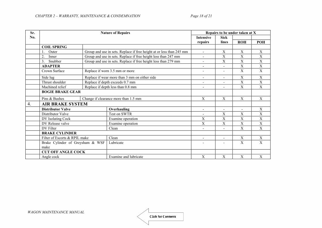
CHAPTER 2 – WARRANTY, MAINTENANCE & CONDEMNATION Page 18 of 21
WAGON MAINTENANCE MANUAL
Sr. No.
Nature of Repairs Repairs to be under taken at X Intensive
repairs Sick lines
ROH POH
COIL SPRING 1. Outer Group and use in sets. Replace if free height at or less than 245 mm - X X X 2. Inner Group and use in sets. Replace if free height less than 247 mm - X X X 3. Snubber Group and use in sets. Replace if free height less than 279 mm - X X X ADAPTER - - X X Crown Surface Replace if worn 3.5 mm or more - - X X
Side lug Replace if wear more than 3 mm on either side - - X X Thrust shoulder Replace if depth exceeds 0.7 mm - - X X Machined relief Replace if depth less than 0.8 mm - - X X BOGIE BRAKE GEAR
Pins & Bushes Change if clearance more than 1.5 mm X X X X 4. AIR BRAKE SYSTEM Distributor Valve Overhauling - - - X Distributor Valve Test on SWTR - X X X DV Isolating Cock Examine operation X X X X DV Release valve Examine operation X X X X DV Filter Clean - - X X BRAKE CYLINDER Filter of Escorts & RPIL make Clean - - X X Brake Cylinder of Greysham & WSF
make Lubricate - - X X
CUT OFF ANGLE COCK Angle cock Examine and lubricate X X X X
Draft

CHAPTER 2 – WARRANTY, MAINTENANCE & CONDEMNATION Page 19 of 21
WAGON MAINTENANCE MANUAL
Sr. No.
Nature of Repairs
Repairs to be under taken at X Intensive repairs
Sick lines
ROH POH
Rubber Seals Change - - X X DIRT COLLECTOR - - - - Dirt Collector Clean - X X X Sealing Ring Change - - X X RESERVOIR AR & CR Drain - X X X Sealing Ring Change - - X X METAL PIPES & JOINTS Pipe Joints Examine leakage & repair X X X X Seals (20 mm & 32 mm)pipe Change X X X X Guard‟s Emergency Brake Valve Examine operation X X X X Isolating cock of BVZC Brake Van -do- X X X X
Quick Coupling -do- X X X X Load Sensing Device -do- - X X X
5. SLACK ADJUSTER ( COMMON FOR ALL) Slack Adjuster Test Functioning, repair if required X X X X “A” dimension Adjust X X X X “e” dimension Adjust - X X X M20 Anchor Pin nut Ensure securing by welding to pin - X X X Air Brake System Test on SWTR as per procedure - X X X Brake Block Ensure Std. Key, Spilt pin & all new brake blocks X X X X NB: For detailed main procedure refer RDSO manual G-97.
Draft

CHAPTER 2 – WARRANTY, MAINTENANCE & CONDEMNATION Page 20 of 21
WAGON MAINTENANCE MANUAL
Sr. No.
Nature of Repairs
Repairs to be under taken at X Intensive repairs
Sick lines
ROH POH
6. CENTRE BUFFER COUPLER ( COMMON FOR ALL) CBC BODY Coupler Body Examine & replace on condition basis - X X X CBC Contour Examine, replace if required - X X X Shank Wear Plate Replace on condition - X X X KNUCKLE Nose Replace if wear more than 9.5 mm with HTE knuckle X X X X Knuckle pin Replace on condition X X X X Knuckle Stretch Examine, Replace if required - - X X STRIKER CASTING Wear Plate Replace - - X X Striker casting Replace on condition - - X X COUPLER MECHANISM Anti Creep Protection Examine and repair X X X X Lock lift assembly Examine X X X X Operation Mechanism Examine X X X X Lock Examine - X X X DRAFT GEAR Slack Measure & take correction - - X X GENERAL Yoke pin support Replace on condition - X X X Buffer Height Examine & Correct if required X X X X NB: 1. For detailed maintenance Practices in open line refer RDSO‟s Manual G-76
2. For detailed maintenance Practices in Workshop refer RDSO‟s Manual G-80 3. Knuckle with nose more than 4.3 mm and less than 9.0 mm can be used in yard.
Draft

CHAPTER 2 – WARRANTY, MAINTENANCE & CONDEMNATION Page 21 of 21
WAGON MAINTENANCE MANUAL
Sr. No.
Nature of Repairs
Repairs to be under taken at X Intensive repairs
Sick lines
ROH POH
7. WHEEL AXLE & BEARING ( COMMON FOR ALL)
AXLE Ultrasonic Testing (If wheel is changed) To be carried in every
ROH/POH & reject if fails - - X X
Deep Notches due to gearing of pull rod Reject if depth is more than 5 mm X X X X Axle end holes Clean and lubricate in case end cover is opened - X X X WHEEL Tread profile Check with tyre defect gauge X X X X Height of flange If height more than 31 mm do not use under ROH wagon - - X X Smooth flange If flange not completely smooth do not use under ROH wagon - - X X Wheel profile Turn to WWP if above clauses are not met for use under ROH wagon. - X X X BEARING TAPERED CARTRIDGE Cup Rotate the bearing for unusual sound check up for Crack/chipping - - X X Seal Check seal for external damage/dent
- X X X
Backing Ring Check backing ring for looseness & vent fitting on backing ring with vent hole ( the vent fitting should be intact or the vent hole should be plugged)
- - X X
Locking Plate Use new locking plate when ever and cover is opened - - X X Axle end Cap screw Clean and lubricate in case end cover is opened - - X X Load Zone Change Change load zone area of the cup while lowering bogie side frame - - X X
Draft

CHAPTER 2 – WARRANTY, MAINTENANCE & CONDEMNATION Page 22 of 21
WAGON MAINTENANCE MANUAL
NOMINAL & MAXIMUM CLEARANCES IN CASNUB BOGIE
S.
No. Particular Type Measurement of location Total Clearance in Nominal
Clearance New At ROH Cond. New ROH Max
1. Lateral clearance between S.F. Column sides All 216 209 206 18 32 38 183 „Bolster column jib All 234 241 244 2. Lateral clearance between a. S.F. Pedestal sides 22W,22W(M) I/II 105 102 101 25 34 35 25+3/-0 b. S.F. Pedestal sides Adapter (wide jaw) I/II 130 136 136 3. Lateral clearance between a. S.F. Crown sides I/II 152 147 144 4 17 20 4+/-0 Adapter crown (wide jaw) I/II 156 164 164 b. S.F. Crown sides NL 152 147 144 3.5 16.5 19.5 3.5+/-0 Adapter Crown NL 155.5 163.5 163.5 4. Long clearance between a. S.F. Pedestal jaw I 270 275 278 2 13 16 2+/-0 Adapter I 268 262 262 b. S.F. Pedestal jaw II 278 283 286 10 21 24 10+5/-0 Adapter II 268 262 262 c. S.F. Pedestal jaw NL 190 195 198 9 20 23 9+2/-3 Adapter NL 181 175 175 5. Long clearance between Side frame column All 450 455 458 6 13 20 6+/-0 Bolster land surface All 444 442 438 6. Clearance between Anti rotation lug All 522 526 528 4 12 16 4+3/-0 Bolster rotation stop lug All 518 514 512 Ref: RDSO manual G-95 and Review of ROH issued by RDSO L.No. MW/BOXN/Maint. Dt. 16.1.95 of DG(W)
Draft

CHAPTER 3- YARD MAINTENANCE Page 1 of 37
WAGON MAINTENANCE MANUAL
1
(WAGON MAINTENANCE MANUAL- 2013)
CHAPTER – 3
YARD
MAINTENANCE
Draft

CHAPTER 3- YARD MAINTENANCE Page 2 of 37
WAGON MAINTENANCE MANUAL
2
CHAPTER 3
YARD MAINTENANCE
The efficient working of freight stock is closely linked to the standard of yard maintenance. Several factors are responsible for good and quality examination/repairs in the yard. The method of examination is described in the succeeding paragraphs.
301. PATTERN OF FREIGHT TRAIN EXAMINATION:
Comprehensive instructions regarding the pattern of freight train examination and issue of Brake Power Certificate have been issued by Railway Board in the form of Joint Procedure Order vide letter No.94/M(N)/951/57 dated 28.2.2000 ( Para 314).
302. NOTIFICATION OF EXAMINATION POINTS:
A) All goods trains must invariably be given Intensive Examination for repairs.
B) Railways should notify nodal points authorise to issue intensive brake power certificates for running of air brake trains on End-to-End basis, Premium Examination and in Close Circuits. These nodal points should have adequate facilities like cemented pathways, welding points, proper lighting etc. for proper examination of air brake trains.
C) Intensive BPC to be issued from nodal examination points only.
D) As a special case, a Safe-to-Run certificate/ GDR certificate may be issued from examination points other than the nodal points for empty journey of air brake stock after unloading up to the first/nominated nodal point in the direction of movement as mentioned in para 314.
303. FREQUENCY OF INTENSIVE EXAMINATION FOR
DIFFERENT STOCK:
A) All freight trains should be subjected to intensive examination in empty condition at originating stations.
B) In exceptional cases the back loaded freight trains can be examined as per instructions mentioned in para 314 item 1 (v).
C) All freight trains shall be re-examined if stabled for more than 24 hours by SSE/JE (C&W) in yard and by guard and Loco Pilot in non C&W station up to next C&W point in the direction of movement for examination, as per Railway Board‟s Joint Procedure Order placed at para 314.
D) Air brake stock shall run on end-to-end pattern as mentioned in para 314. The intensive BPC shall remain valid provided:
i. The destination is mentioned on the BPC of the loaded train. ii. The composition of the rake is not changed by 4 or more wagons.
Draft

CHAPTER 3- YARD MAINTENANCE Page 3 of 37
WAGON MAINTENANCE MANUAL
3
iii. The rake is not stabled for more than 24 hours.
E) Air brake stock shall run on nominated Close Circuit as mentioned in para 314. The intensive BPC issued at the nodal point shall remain valid provided:
i. The kilometrage have been logged in correctly and continuously. (If
not, BPC will be deemed to be valid for 15 days only from the date of issue of BPC.)
ii. The rake integrity is not changed and only the listed wagons are included.
iii. The rake is not stabled for more than 24 hours. iv. The rake is running in the predefined circuit as mentioned on the BPC.
(Breaking the rake into parts and reforming the same parts, will not be deemed to have broken the rake integrity)
F) No intermediate examination of the Close Circuit rake is required. It would be the responsibility of the Driver and Guard to check the unloaded CC rake at the unloading point and ensure brake continuity before starting.
G) All close circuit freight trains will be given intensive examination during day light hours.
H) BPC issued after intensive examination in empty condition must be revalidated after loading. Revalidation includes conducting brake continuity test, ensuring completeness/securing of brake gears only and endorsing on intensive BPC. No detachments unless safety is affected.
304. STEPS OF INTENSIVE EXAMINATION
A) Rolling-in-examination including axle box feeling. B) Intensive examination of originating trains including repairs, detachment of
damaged/sick wagons, brake testing etc. C) Issue of Intensive Brake Power Certificate after ensuring brake continuity of the
formed load.
For loads requiring sorting and/or having different terminating and originating yards/locations, the steps for issuing intensive BPC will be as follows: i. Rolling-in-examination including axle box feeling (same as para 305 A).
ii. Terminating examination including detachment of damaged/sick wagons (given in para 305 D).
iii. Intensive examination of originating trains including repairs, brake testing etc. (Same as para 305 B).
iv. Issue of Intensive Brake Power Certificate after ensuring brake continuity of the formed load (same as Para 305 C).
305. DETAILS OF INTENSIVE EXAMINATION:
305A. ROLLING-IN-EXAMINATION INCLUDING AXLE BOX FEELING -
All terminating trains should be given rolling in examination while entering a station/yard with a train examination depot. To carry out this examination the Train
Draft
CHAPTER 3- YARD MAINTENANCE Page 4 of 37
WAGON MAINTENANCE MANUAL
4
Examiner and his staff should take up positions on both sides of the lines short of the normal halting place on which the train is to be received. The following inspection should be carried out during the rolling in examination:
i. In motion inspection and observation of under gear of wagons for any loose or
dangling components and flat places on tyres/wheels.
ii. Immediately after the train has come to a halt, all axle boxes should be felt/ temp. measurement taken with contact-less thermometers and those, which are found running at high temperature(More then 90 0C), should be marked sick for opening/checking at the time of examination and attention if necessary.
iii. Examination of any abnormal behaviour of any of the vehicles or any other observation which may relate to unsafe working condition.
iv. The rolling in examination must be conducted to detect any skidded wheel. Defect in the brake system or faulty manipulation by the driver may cause skidding of wheels.
v. Incoming BPC should be collected by yard C&W staff. 305B. INTENSIVE EXAMINATION AND REPAIRS -
Once, the train has been offered for examination by Traffic Department, the rake should be protected at both the ends before undertaking the following examination and repair activities:
i. Inspection and repairs of running gear fittings. ii. Inspection and repairs of brake gear and spring gears. iii. Inspection and repairs of draw and buffing gear. iv. Checking and making good the deficiency of safety fittings, safety brackets,
safety loops, etc. v. Replacement of brake blocks:
Brake blocks should be replaced on reaching condemning thickness as given in para 307 A.
Cast iron brake blocks as per RDSO drawing No. WA/BG-6158 with latest alteration or composite brake blocks should be used.
Worn out composite brake blocks should be replaced with composite brake blocks.
To ensure correct fitment of brake blocks, only spring steel key as per RDSO Drg. No. W/BG-6150 should only be used.
After fitment of brake block and key on brake head fitment of split pin should be ensured.
vi. Correct fitment of washers, bulb cotters and all brake gear pins to be ensured.
vii. Correct functioning and positioning of empty load device. viii. CTRB stock found running at high temperature may be taken in sick lines
for further attention
Draft

CHAPTER 3- YARD MAINTENANCE Page 5 of 37
WAGON MAINTENANCE MANUAL
5
ix. Checking and proper securing of doors of covered wagons. x. Look for abnormal and /or unequal buffer heights/CBC height, wear plate
knuckle, etc. to the extent it is possible to detect by visual examination. In case of doubt, the buffer height/CBC height should be measured.
xi. Meticulous check of brake cylinders, distributor valves, auxiliary reservoir control chambers and other pipe points should be carried out to ensure that these are in proper working order. Isolating cocks and angle cocks to be checked for proper position. Brake cylinder should be released and checked for piston stroke as per para 307 B for empty and loaded position.
xii. After brakes are released, the wheel profile should be examined visually. If any defect is noticed, it should be checked with tyre defect gauge and wagon to be marked sick for wheel changing, if required. If bent axle is suspected wheel gauging must be done.
xiii. The bogies, complete side frames and bolsters to be visually examined for cracks and missing parts. Bolster springs, snubbers, spigots, centre pivots fastening, side bearer and Elastomeric pads in case of CASNUB 22 bogie to be checked for defects, if any.
xiv. Examine brake rigging components with special attention to brake beam deformation and wear on integral brake shoe bracket. Check intactness of the pull and push rods with pins, washers, split pins and cotters, etc. Hand brakes must be checked for smooth and effective operation.
xv. Visual examination of under frame members, body, door mechanism, CBC wear or deficiency of parts to be marked and their operation to be checked.
xvi. Brake power should be tested. xvii. Examination of loaded stock should be done as per IRCA part-III. xviii. Examination of tank wagons should be done as per IRCA Part-III. xix. Where a rejectable defect can not be attended to on the train in the
yard, the wagon shall be damaged labelled for attention in the sick line.
xx. Brake adjustment shall be done as per wheel diameter by adjusting End Pull Rod hole position.
xxi. Visual examination of under frame members, body, door mechanism for any defects/ damages. Attend, if necessary.
305C. ISSUE OF INTENSIVE BRAKE POWER CERTIFICATE –
i) All freight trains after being subjected to intensive examination will be given a
Brake Power Certificate. ii) The standard formats for Brake Power Certificate are enclosed as
ANNEXUREs. iii) The brake power certificates of air brake stock will be Green. The colour of
BPC for Premium and CC Rakes shall be light green and yellow respectively.
iv) The minimum originating brake power for air braked goods trains, running on end-to-end pattern of examination, shall be 90% except wherever local
Draft

CHAPTER 3- YARD MAINTENANCE Page 6 of 37
WAGON MAINTENANCE MANUAL
6
instructions have specified higher level of brake power to meet specific requirement. Exception shall only be made after prior approval of Chief Rolling Stock Engineer has been obtained for each individual case.( Reference RB‟s letter No.94/M(N)/951/57 dated 29.9.95)
v) The originating brake power for air braked goods trains, running in close circuits shall be 100 % with adequate brake block thickness. The originating brake power for air braked Premium rakes shall be 95%.
vi) As far as possible, the close circuit air brake rakes should be formed by off-ROH and off-POH wagons for better monitoring.
vii) No fresh Brake Power Certificate shall be issued during revalidation.
viii) No Safe-to-Run BPC shall be issued from nodal points.
ix) Brake pipe pressure required in the air braked train with locomotive should be as follows:
TABLE 3.1 Brake pipe pressure required in the train
No. of wagons On Locomotive Min. on last wagon Up to 56 5.0 Kg/Cm2 4.8 Kg/Cm2
Beyond 56 5.0 Kg/Cm2 4.7 Kg/Cm2 xiii) The following procedure should be followed to issue the BPC after
attachment of the locomotive: All BP hoses/ hose pipes on the train should be coupled up. The angle
cocks in case of air brake stock at both ends of the wagon in brake pipe should be open. The angle cock at the end of air brake van must be in closed position.
Attach front wagon BP hose to BP hose of the locomotive.
Ensure firmness and tightness of hoses with palm ends coupling and clips. Ensure that all the cut off angle cocks on brake pipes are in open position
in case of air brake stock. Attend to all leaks by replacing MU washer, leaky hoses and angle cock
assembly, if requisite BP pressure is not coming in the last vehicle. Inoperative or defective brake cylinders should be isolated by putting the
isolating cock handle in close position.
305D. TERMINATING EXAMINATION OF STOCK REQUIRING SORTING AND/OR HAVING DIFFERENT TERMINATING AND ORIGINATING YARDS/LOCATIONS : Examination of terminating load should be carried out as soon as the train has come to a halt. The examination would consist of the following: - i) All under gear fittings including brake gear, draw and buffing gear and spring
gear, air brake, under frame, body, door mechanism, bogies, wheels, axle, etc. should be examined for being in sound condition and with all fittings intact.
ii) The tyre profiles should be checked to ensure that rejectable defects have not arisen. In doubtful cases, use of the tyre defect gauge should be made for this purpose.
Draft
CHAPTER 3- YARD MAINTENANCE Page 7 of 37
WAGON MAINTENANCE MANUAL
7
iii) Ensure functioning and position of load/empty device. iv) CTRB stock found running at high temperature may be taken in sick lines for
further attention. v) Other items to be checked in case of air brake stock are as follows:
Meticulous check of brake cylinders, distributor valves, auxiliary reservoir control chambers and other pipe points should be carried out to ensure that these are in proper working order. Isolating cocks and angle cocks to be checked for proper position. Brake cylinder should be released and checked for piston stroke as per para 307 B for empty and loaded position.
During terminating examination, special care should be exercised for any deficiencies, damages, leaky components, malfunctioning of distributor valves, brake cylinders, control and auxiliary reservoirs, angle cocks, BP hoses so that necessary replacement and repairs can be executed to minimise attention during outgoing examination.
vi) In case of terminating loading trains to be subjected to tippler for unloading, the Brake power available on train should be recorded deficiencies noticed should be chalk marked so that after unloading/Tippler operation, deficiencies can be identified and replaced during outgoing examination.
vii) Where a rejectable defect is not expected to be attended to on the train during the subsequent outgoing examination in the yard, the wagon shall be sick marked/ damaged-labelled for attention in the sick line.
306. AIR BRAKE TESTING :
A rake consisting of air brake wagons should be tested with rake test rig. This rig may be used for testing the train in yard before attaching the engine. The rake test rig has compressed air supply and a mobile test rig. The mobile test rig has a cubical structure and is mounted on wheels.
i) Attach the locomotive/compressor through the test rig to the train & couple brake pipes. Ensure correct coupling with pipes so that there is no leakage of air from coupled joints
ii) The coupling should be done with angle cocks in closed position. iii) Open the angle cocks of loco after coupling brake pipe. iv) Open the angle cock of the brake pipe on all the wagons. Check for continuity of
brake pipe by reducing and rebuilding brake pipe pressure. The verification should invariably be carried out through the pressure gauge provided in Guard‟s Brake Van.
v) After the brake pipe pressure has stabilised in the locomotive and rearmost vehicle, move the driver‟s automatic brake valve handle towards application position to reduce the brake pipe pressure from 5 kg/cm2 to 4 kg/ cm2
vi) After the brake pipe pressure has been stabilised, close the brake pipe isolating cocks provided between additional C2 relay valve and brake pipe of the locomotive.
vii) Wait for 60 seconds for temperature and gauge settlement. Then note the drop in pressure in the brake pipe gauge in the locomotive for five minutes.
Draft

CHAPTER 3- YARD MAINTENANCE Page 8 of 37
WAGON MAINTENANCE MANUAL
8
viii) The drop in brake pipe pressure gauge shall not be more than 0.25 kg/cm2 per minute.
ix) Examine for leaky components, malfunctioning of distributor valves, brake cylinders, control and auxiliary reservoirs, angle cocks, BP hoses.
x) If the leakage rate is more then the value indicated in para viii, check for excessive leakage on individual wagon as indicated below:
A hissing sound would be audible at points where leakage is heavy. Once the hissing sound is heard from a particular area, pin point the
location of leakage by applying soap water solution Use of permitted material viz. Teflon tape for arresting the leakage at
threaded joints. xi) In case leakage is heavy and cannot be arrested, the wagon may have to be
isolated/detached xii) In case where leakage can be arrested temporarily by tape and the nature of
leakage is such that it requires attention at primary depot, clear marking on the wagon must be made to draw attention of primary depot for adequate attention.
xiii) In case the leakage is from the distributor valve and cannot be arrested, close the
distributor valve isolating cock. In such a condition, clear marking should be provided on the wagon to indicate this defect to primary depot. Do not close brake pipe angle cocks under any circumstances either for isolation of wagons or for any other purpose whatsoever except for carrying out shunting operation after which the angle cocks should again be opened to ensure continuity of brake pipe.
307. IMPORTANT PARAMETERS TO BE ENSURED DURING INTENSIVE
EXAMINATION: 307 A. BRAKE GEAR LIMIT AND CLEARANCES:
Description Limit Brake block condemning limits 10 mm Yard leaving thickness of brake block except BOY wagon 20 mm „A‟ dimension of air brake stock fitted with CASNUB bogie except BOBRN wagon
70 mm +2 - 0
„A‟ dimension of BOBRN wagon 27 mm +2 - 0
Draft

CHAPTER 3- YARD MAINTENANCE Page 9 of 37
WAGON MAINTENANCE MANUAL
9
307B. PISTON STROKE:
Type of wagon Piston Stroke Empty Loaded
BOXN, BCN/BCNA, BRN, BTPGLN, 85 mm +/- 10 130 mm +/- 10 BOXNHL, BCNHL 85 mm +/- 10 120 mm +/- 10 BTPN 87 mm +/- 10 117 mm +/- 10 BOY 90 mm +/- 10 135 mm +/- 10 BVZC 70 mm +/- 10 BOBRN 100 mm+/-10 110 mm+/- 10 BOBYN 100 mm+/-10 110 mm+/- 10 BVZI 45 mm+/- 10
307C. BUFFER HEIGHT :
Description Limit
Buffer height from Rail level
Max. 1105 mm (Empty) Min. 1030 mm (Loaded)
308. IMPORTANT PARAMETERS TO BE ENSURED DURING SICK LINE/ DEPOT ATTENTION
308 A. NOMINAL CLEARANCES OF CASNUB BOGIES
Description 22W 22W(RETRO)
22W(M) 22NL NLB, NLM, NLC
22HS HS(MOD1), HS(MOD2), IRF108HS
Lateral clearance between side frame and bolster
18 mm 18 mm 18 mm 25 mm
Lateral clearance between side frame and axle box/adopter
25 mm 25 mm 16 mm 16 mm
Longitudinal clearance between side frames and axle box/adopter
2 mm 10 mm 9 mm 9 mm
Longitudinal clearance between side frame and bolster
6 mm 6 mm 6 mm 6 mm
Clearance between anti rotation lug and bolster
4 mm 4 mm 4 mm 4 mm
308 B. WEAR LIMITS :
Description Limits Adapter Thrust shoulder 0.7 mm Adapter Crown lugs 4.0 mm Adapter crown seat 3.5 mm Adapter side lugs 3.0 mm Adapter sides 3.0 mm
Draft

CHAPTER 3- YARD MAINTENANCE Page 10 of 37
WAGON MAINTENANCE MANUAL
10
Side frame column friction plate 4.0 mm Side frame column sides 5.0 mm Side frame anti rotation lug 3.0 mm Pedestal crown roof 5.0 mm Pedestal crown sides 4.0 mm Pedestal sides 2.0 mm Pedestal jaw 4.0 mm Bolster liner wear limit 5.0 mm Bolster land surface 3.0 mm Bolster column sides – Inner/Outer 5.0 mm
308 C. LOAD/SNUBBER SPRINGS OF CASNUB
Type of Bogie Location Free Height Nominal (mm)
Free condemning height (mm)
CASNUB 22W, W(Retro), W(M), NL, NLB, NLM & NLC
Outer Inner Snubber
260 262 294
245 247 279
CASNUB 22 HS Outer Inner Snubber
260 243 293
245 228 278
CASNUB 22 HS (MOD-I) Outer Inner Snubber
253 225 304
238 210 289
CASNUB 22 HS (MOD-II) Outer Inner Snubber
253 222 304
238 207 289
308 D. WEAR LIMIT FOR FRICTION WEDGE BLOCK
Vertical Surface 7 mm Slope Surface 3 mm
308 E. CENTRE PIVOT WEAR LIMIT
CASNUB 22(W) OTHERS Vertical sides 5.5 mm 4.0 mm Seat 4.0 mm 4.0 mm
308 F. ELASTOMERIC PAD & CONSTANT CONTECT SIDE BEARER:
Description Nominal dimension Dimension after permanent set (condemning size)
Elastomeric Pad 46 mm 42 mm Constant contact side bearer pad a). Metal Bonded rubber pad 114 mm
(pad only) 109 mm
b). PU CCSB for CASNUB 22HS
142.5 mm (With three rings)
137
Draft
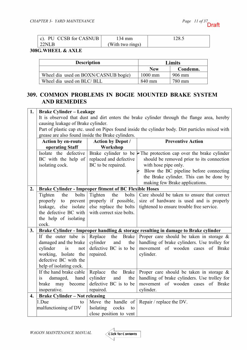
CHAPTER 3- YARD MAINTENANCE Page 11 of 37
WAGON MAINTENANCE MANUAL
11
c). PU CCSB for CASNUB 22NLB
134 mm (With two rings)
128.5
308G. WHEEL & AXLE
Description Limits New Condemn.
Wheel dia used on BOXN/CASNUB bogie) 1000 mm 906 mm Wheel dia used on BLC/ BLL 840 mm 780 mm
309. COMMON PROBLEMS IN BOGIE MOUNTED BRAKE SYSTEM
AND REMEDIES
1. Brake Cylinder – Leakage It is observed that dust and dirt enters the brake cylinder through the flange area, hereby causing leakage of Brake cylinder. Part of plastic cap etc. used on Pipes found inside the cylinder body. Dirt particles mixed with grease are also found inside the Brake cylinders.
Action by en-route operating Staff
Action by Depot / Workshop
Preventive Action
Isolate the defective BC with the help of isolating cock.
Brake cylinder to be replaced and defective BC to be repaired.
The protection cap over the brake cylinder should be removed prior to its connection with hose pipe only.
Blow the BC pipeline before connecting the Brake cylinder. This can be done by making few Brake applications.
2. Brake Cylinder - Improper fitment of BC Flexible Hoses Tighten the bolts properly to prevent leakage, else isolate the defective BC with the help of isolating cock.
Tighten the bolts properly if possible, else replace the bolts with correct size bolts.
Care should be taken to ensure that correct size of hardware is used and is properly tightened to ensure trouble free service.
3. Brake Cylinder - Improper handling & storage resulting in damage to Brake cylinder If the outer tube is damaged and the brake cylinder is not working, Isolate the defective BC with the help of isolating cock.
Replace the Brake cylinder and the defective BC is to be repaired.
Proper care should be taken in storage & handling of brake cylinders. Use trolley for movement of wooden cases of Brake cylinder.
If the hand brake cable is damaged, hand brake may become inoperative.
Replace the Brake cylinder and the defective BC is to be repaired.
Proper care should be taken in storage & handling of brake cylinders. Use trolley for movement of wooden cases of Brake cylinder.
4. Brake Cylinder – Not releasing 1.Due to malfunctioning of DV
Move the handle of Isolating cocks to close position to vent
Repair / replace the DV.
Draft

CHAPTER 3- YARD MAINTENANCE Page 12 of 37
WAGON MAINTENANCE MANUAL
12
the air from brake cylinder. Isolate the DV by moving the R-charger handle to close position.
2. Due to malfunctioning of BC
The internal mechanism of brake cylinder is damaged. Isolate the defective BC with the help of isolating cock. It will release the air pressure from the Brake cylinder. If this doesn‟t work, remove the pin connecting the push rod and lever to free the system. Suitably tie the push rod and lever to prevent it from touching the wheel.
Replace the Brake cylinder and same to be repaired. Re-connect the system and provide the necessary APDs. Apply brakes to adjust the system.
5. APM Device – Improper fitment The bracket of APM Device is not properly fitted on the underframe, as a result, the sensor arm is not properly touching the side frame on the Bogie.
Action by en-route operating Staff
Action by Depot / Workshop
Preventive Action
No action is possible. The position of the bracket is to be corrected to ensure that the working of APM valve is proper.
Care should be taken during the welding of APM Device bracket on under-frame. It should be ensured that the sensor arm is correctly touching in the centre of the side frame.
6. APM Device – Improper fitment of flexible hoses If the APM Device flexible hoses are not properly fitted, they can get cut / damaged. Tie the flexible hose properly through some suitable means to under-frame member.
Provide suitable clamp to ensure that the flexible hose is not loosely hanging.
Care should be taken during the fitment by providing suitable clamp / bracket.
7. APM Device – Leakage from the mounting bracket connecting the pipes Action by en-route
operating Staff Action by Depot /
Workshop Preventive Action
Tighten the bolts properly to prevent leakage.
Tighten the bolts properly if possible. In case an incorrect bolt size has been
Care should be taken to ensure that correct size of bolts are used and properly tightened to ensure trouble free service.
Draft

CHAPTER 3- YARD MAINTENANCE Page 13 of 37
WAGON MAINTENANCE MANUAL
13
used, it could have damaged the bracket also. Bracket needs to be replaced.
8. Missing of split pins – Brake Head Damage / Missing The absence of split pin above Brake head pin con result in pin moving out. Further, this could result in dropping of brake head and thereby causing the Brake Beam to touch the wheel and get damaged. Isolate the bogie by operating the isolating cock to close position.
Install the new parts which have been damaged. Provide split pins & APDs in a proper manner.
Care should be taken to ensure that split pins and APDs are properly provided.
9. Missing of split pins – Bogie Components damaged Isolate the bogie by operating the isolating cock to close position.
Install the new parts which have been damaged. Provide split pins & APDs in a proper manner.
Care should be taken to ensure that split pins and APDs are properly provided.
10. Missing of APDs – Split pin used on Brake Cylinder Pin Action by Depot / Workshop Preventive Action
Provide the bush and dowel on the pin.
Care should be taken to ensure that the bush and the dowel should be used on brake cylinder mounting pins.
11. Missing of APDs – On the pin of Primary Brake Beam APDs to be provided over the mounting pins.
Care should be taken to ensure that the mounting pins are provided with APDs.
12. Missing of APDs – On the pin of Secondary Brake Beam Action by Depot / Workshop Preventive Action
APDs to be provided over the mounting pins.
Care should be taken to ensure that the mounting pins are provided with APDs.
13 Missing of APDs – On the pin of Push Rod Action by Depot / Workshop Preventive Action
APDs to be provided over the mounting pins.
Care should be taken to ensure that the mounting pins are provided with APDs.
14. Inappropriate APDs on APM Device Proper APD to be provided over the APM Device.
Care should be taken to ensure that the APD provided on the APM Device is appropriate so that it perform its intended function.
15. Hand brake - Incorrect location of Brackets Brackets to be moved to its correct location as per RDSO drawing.
Care should be taken to ensure that the brackets locations are correct as per the drawing. This can be checked by applying the brakes for proper functioning.
16. Missing of APDs – On the pin of Primary Brake Beam APDs to be provided over the Care should be taken to ensure that the mounting pins
Draft

CHAPTER 3- YARD MAINTENANCE Page 14 of 37
WAGON MAINTENANCE MANUAL
14
mounting pins. are provided with APDs. 17. Missing of APDs – On the pin of Secondary Brake Beam
Do the necessary correction and check whether the brakes are functional.
Care should be taken during the fitment of hand brake arrangement. Check the working of the hand brake arrangement by applying the brakes.
18. Missing of APDs – On the pin of Secondary Brake Beam Action by en-route
operating Staff Action by Depot /
Workshop Preventive Action
Tie the hanging part to the under frame to prevent it from touching the moving parts of wagon.
Install new component. Provide the APDs to prevent re-occurrence.
APDs should be provided to prevent the moving out of components during service.
19. Wrong use of Isolating cock in BC Line In case, wherein wrong isolating cock has been used, if required isolate the wagon through DV instead of bogie.
Replace the isolating cock to with-vent type and check its working.
Care should be taken to use isolating cocks with vent in the BC line. During the testing, check the vent position of isolating cock by moving the handle to close during application and ensuring that the BC pressure gets exhausted.
310. INFRASTRUCTURE & FACILITIES REQUIRED IN THE YARD
(Please refer to Chapter 11 on Infrastructure Facilities)
311. MACHINERY & PLANT ITEMS
(Please refer to Chapter 11 on Infrastructure Facilities)
312. TOOLS REQUIRED
(Please refer to Chapter 11 on Infrastructure Facilities)
313. MAN HOURS FOR VARIOUS TYPES OF EXAMINATIONS
The man-hours for examination of various types of stock are given below as a guideline. Zonal railways may however permit variation based on local conditions, typical characteristics prevailing at site and availability of infrastructural facilities.
TABLE 3.2 Man-hours for examination of various types of stock
Stock Type of Examination Terminating Intensive Originating
Air Brake (End-to-End running)
6 56 10
Air Brake (Premium) 6 75 10 Air Brake(Close Circuit) 6 100 10
The distribution of intensive staff gang wise with tools and material is given in Table 3.3.
Draft

CHAPTER 3- YARD MAINTENANCE Page 15 of 37
WAGON MAINTENANCE MANUAL
15
314. PROCEDURE ORDER FOR RUNNING OF GOODS TRAINS ( Railway Board’s letter No.94/M(N)/951/57 dated 28.2.2000) At present, practices for the issue of BPC to freight trains vary considerably between various Zonal railways. The matter has been considered in the Railway Board and the following comprehensive instructions are issued.
ITEM 1: END TO END RUNNING OF UIC RAKES
Para has been deleted (Refer old version-2001 of maintenance manual)
ITEM 2: END TO END RUNNING OF AIR BRAKE STOCK
i) The rake should normally be intensively examined in empty condition except
when back loading of rake has to be done at stations/sidings. After such intensive examination, the empty rake should be moved to the loading station as per the requirement of traffic.
ii) The BPC of empty rake may have no destination mentioned. But, after loading the empty rake, the operating staff (commercial staff, if not operating staff is posted at that station) will ensure that the destination of the loaded train is clearly mentioned on the BPC and the same BPC will then become valid upto such destination.
iii) No driver should move the loaded train from the loading point unless the destination is clearly mentioned on the BPC. BPC of the loaded train without destination will be considered as invalid.
iv) At the destination after unloading, the rake must be examined once again in the empty condition and the above cycle repeats. In the absence of freight train examination facilities at the unloading point, the empty rake/back loaded rake must be examined at the first freight train examination point in the direction of movement. The movement of empty rake/back loaded rake from the unloading point to the first freight train examination point will be permitted on Driver and Guard‟s certificate for which the following instructions should be followed: a) Driver and Guard will ensure vacuum/air pressure continuity before
starting. b) Guard and the Driver will ensure that there are no loose or missing
fittings in the under gear (such as brake blocks, safety brackets, draw gear pins, brake gear pins etc.) which may endanger the safe running of the train.
c) Driver and Guard can then prepare the memo jointly on a plain sheet in triplicate and both Driver and Guard will sign it. One copy each will be retained by the Driver and Guard and third copy will be handed over to Station Master.
Condition (I) to (V) mentioned above shall apply for end-to-end running of Air Brake stock. However, since these rakes are likely to run for extended periods on each
Draft
CHAPTER 3- YARD MAINTENANCE Page 16 of 37
WAGON MAINTENANCE MANUAL
16
loading cycle, the examination should be through and intensive to take care of such long runs.
In case empty rakes are moving on Safe to run examination BPC, the rake will
be dropped for intensive examination at nominated point before being taken for loading. ITEM 3: BACK LOADING OF TRAINS
When back loading is done at a station where freight train examination facilities exist, the loaded rake should be examined at that station only and BPC issued. In cases where back loading is done at a non-TXR station, such trains can be:
a) Either checked by flying squad, if operationally feasible. b) Or, if that is not possible, permitted to run on a driver & Guard‟s memo for
which the instructions given above (iv) should be followed.
Running of trains on Driver and Guard‟s memo will be permitted only up to the first freight train examination point in the direction of train movement. ITEM 4: VALIDITY OF BRAKE POWER CERTFICATE FOR CLOSE
CIRCUIT AIR BRAKE RAKES
A per instructions issued vide Board‟s letter No. 87/M(N)/951/31 dt. 22.8.1994, BPC of air brake stock running in close circuit shall remain valid for 4500 kms. In case it is seen that the record of the distance covered by the rake is discontinuous or not mentioned properly, the BPC will be deemed to be valid for only 15 days from the date of issue. It is the responsibility of the crew to check that entries regarding distance are clearly and continuously recorded. ITEM 5: STANDARDISATION OF BRAKE POWER CERTIFICATE FOR
AIR BRAKE CLOSE CIRCUIT RAKES
Standard formats of BPCs of CC/ Premium/ end to end are given as annexure.
315. PROCEDURE FOR EXAMINATION & SAFETY CERTIFICATION OF DEPARTMENTAL ROLLING STOCK:
Examination and certification of the safety of wheels, under gear and structure
of Brake Down crane is the responsibility of the Mechanical supervisor (SSE/Loco/Diesel/ C&W), who is the custodian of the crane. The safety certification shall be carried out at a periodicity of 30 days. Similarly, self propelled ART/ARMEs are also to be examined and certified for the safety of structure and under gear at a periodicity of 30 days by the nominated Mechanical Supervisor (Loco/Diesel/ C&W Supervisor).
i. All the departmental wagon stock which may run with goods trains, like camping, mobile training cars, OHE wiring trains etc. shall be allotted a C&W depot for Primary maintenance nominated by Chief Mechanical Engineer (or by nominated
Draft

CHAPTER 3- YARD MAINTENANCE Page 17 of 37
WAGON MAINTENANCE MANUAL
17
Mechanical Officer). The allotted depot shall be painted on the stock end wall. Wheels, under gear and structure of the stock shall be examined for safety and certified by the Mechanical Supervisor at the nominated C&W depot. This certificate shall be valid for a maximum period of 30 days from the date of issue.
ii. Rolling stock, which cannot be dispatched to the nominated depot for primary maintenance shall be offered to the C&W Supervisor at the nearest Train Examination point for inspection and certification of wheels, under gear and structural safety. This certification shall be valid for 30 days from the date of issue
iii. All departmental wagons in material trains/ballast trains/PQRS trains etc. shall be examined in terms of IRCA Pt.III 3.2.1. A detailed joint circular shall be issued by a Committee consisting of CME, CE & COM of the zonal railway or their nominated officers, which inter alia should include detailed guidelines for examination by C&W Supervisor for running of departmental trains/PQRS rake.
iv. Tower wagons shall be inspected for safety in terms of Para 20317(2) of AC Traction manual by the Mechanical Supervisor (C&W Supervisor) of the nominated C&W depot nearest to the TRD depot where the Tower wagon is based. The base depot of the Tower wagon shall be painted on its end wall. For this purpose, C&W depot shall be nominated by Sr.DME/DME of the division in consultation with concerned Sr.DEE/TRDs. The certification shall be valid for a maximum period of 30 days/4500 kms, whichever is earlier. Thereafter, the Tower wagon shall be offered to the nominated C & W Supervisor for examination and safety certification again. In case, the Tower wagon is operating in a division away from the nominated depot, the same shall be offered to the nearest Train examining point for C&W examination as soon as the validity of the certificate expires.
v. Track machines shall also be subjected to wheel, under gear and structural safety examination and certification by the Mechanical Supervisor at periodic intervals as decided by concerned Zonal Railways.
vi. Notwithstanding the above periodic inspection by the nominated C & W Supervisor/Mechanical Supervisor, the Supervisor in charge/custodian of the rolling stock in question shall carryout inspection of the rolling stock before starting the operation. In case he notices/suspects any abnormality in the rolling stock regarding structural and under gear safety, he shall immediately arrange to offer the rolling stock for C & W examination afresh.
The Station Master shall not give permission to start the departmental train/any departmental rolling stock unless the supervisor in charge produces the valid safety certificate issued by the nominated Mechanical Supervisor in terms of GR 4.31 and GR 4.35.( Rly.Bd's Letter No.2004/M(Safety)/Deptl.Stock dtd. 20.05.2004.) 316. PREMIUM EXAMINATION
BPC of premium rakes have a validity of 12 days with 3 days additional grace period to facilitate examination in unloaded condition.
The concept of premium rakes is applicable subject to compliance of certain conditions (vide Bd‟s letter no. 2005/ M(N)/951/13 dated 07/10. 04.2006 ) as follows-
Draft
CHAPTER 3- YARD MAINTENANCE Page 18 of 37
WAGON MAINTENANCE MANUAL
18
1. Premium rakes will be formed out of air brake stock (BOXN, BOXNHA & BOXNHS,
BCN, BCNHS).
2. Premium end to end rakes will be intensively examined in empty condition and certified by examination points nominated by CME & COM. Such premium examination points should either be ‘A’ category.
3. If any of the conditions i.e. examination in empty condition or examination at nominated points is not satisfied, rake will not be certified as premium rake and will operate as normal end to end rake.
4. Brake Power Certificate issued for such premium end to end rakes will be valid for 12 days from the date of issue. During this 12 day period, the rakes will be allowed multiple loading / unloading.
5. After each loading / unloading the rake will be examined by Guard and Driver before commencement of journey and observations will be recorded under the relevant columns of the Brake Power Certificate. In case of mechanized loading/ unloading examination by TXR is desirable.
6. Stipulation to form rakes out of off POH/ ROH wagons as is applicable for CC rakes will not apply in case of end to end rakes. However, the rakes will be turned out with minimum 95% Brake Power.
7. After the lapse of 12 days, the rakes should be offered for next intensive examination at the first examination point in the direction of movement. To avoid examination in loaded condition, a grace period of 3 days will be permitted. However, after expiry of the grace period i.e. after a lapse of 15 days after the date of issue of BPC, even a loaded premium rake shall be offered for examination at the first TXR point in the direction of movement. Further, in no case Premium end to end rake shall be offered for loading through bypass routes or through yards which are not nominated for examination. After examination the rake will be certified as premium rake subject to fulfillment of above mentioned conditions, otherwise as conventional end to end rake.
8. Movement of Premium end to end rakes will be monitored thorough FOIS by Traffic and Mechanical departments.
9. The format for Brake Power Certificate for Premium end to end rakes (to be printed on good quality green colour paper) is enclosed.
317. CC RAKES
Vide Bd‟s letter no. 2005/M(N) 951/ 13 dated 08.02.06, CC rakes with validity of BPC for 7500 Kms or 30 days (whichever is earlier) were introduced, as a trial measure, in select base depots i.e. NKJ, MGS, BIA, BNDM, GY & TKD / Dadri ( for CONRAJ Only).
It was decided to extend the above trial to additional 3 base depots i.e. BSL, NJP and VSKP (vide Bd‟s letter no. 2005/ M (N) 951/13 dated 29/31 .01.2007). Also, it was decided to extend the validity of BPC of these rakes from 30 to 35 days).
Draft

CHAPTER 3- YARD MAINTENANCE Page 19 of 37
WAGON MAINTENANCE MANUAL
19
However it was stipulated that the further trial of 6000/ 7500 Kms (or 30/ 35 days whichever is earlier) CC rakes shall be subject to the following conditions. –
i) CC rakes shall be monitored closely through FOIS by all Sr. DOMs to ensure
that these rakes are worked to their respective base depots before completion of stipulated KMs/ days. Rakes with invalid BPC shall normally not to be permitted to run in service.
ii) All the cases of violation of this limit shall be analyzed by the concerned Division/ Zone where such rake gets detected, either on run or during subsequent examination, for adequate corrective and/ or punitive action (if necessary).
iii) In case 7500 Km / 35 days limit is breached due to lack of monitoring or otherwise, and the rake is in empty condition, it shall be pushed to nearest TXR point for safe to run (STR) examination and endorsement on BPC by TXR that the train is safe to run upto the base depot.
iv) Such potentially unsafe rakes mentioned under (iii) above, when detected in loaded condition, shall be subjected to GDR check and pushed to destination. After unloading, the empty rake shall be offered to the nearest TXR point for STR examination and endorsement on BPC that the rake is safe to run in empty condition upto its nominated base depot.
v) The potentially unsafe rakes from the point of detection to the nearest TXR point will move on GDR check.
Further, zonal railways shall maintain detailed record w.r.t. enroute detachments, brake power and detachaments during examination of these rakes and give monthly feedback to board on their performance.
Vide Bd‟s letter no. 2005/ M (N) 951/13 Vol. I dated 17/18.10.2007; it was
decided to extend the trial of these rakes to 3 more CC points viz. BRWD (ECR), JTJ (SR) and RDM (SCR).
Railway must ensure that Infrastructural facilities at all the above points are
upgraded to „A‟ category. 318. POST LOADING AND POST TIPPLING EXAMINATION
Vide Bd‟s letter no. 2005/ M (N)/ 951/ 13 dated 08.02.2006, Post Loading examination by TXR staff was discontinued, post loading check by guard and driver was introduced, In the para (iv) of Bd‟s above letter dated 08.02.06, it was stipulated that:
After tippling the rake will be subjected to post –tippling examination. In case less than 3 rakes are being tippled per day, the check may be carried out by guard and driver as per Proforma enclosed. In case 3 or more trains are being tippled , post tippling check will be done by skeleton TXR staff.
Draft
CHAPTER 3- YARD MAINTENANCE Page 20 of 37
WAGON MAINTENANCE MANUAL
20
The same has been reviewed vide Bd‟s letter no. 98/ M(N)/ 951/ 12/ Pt. 1 dated 17.05.07, and relevant paras are reproduced as follows:
1. Board has reviewed the subject matter and has decided to revise the instructions contained in para (iv) of aforesaid letter dated 08.02.006 on post tippling checks of freight trains as under:
a) After tippling, rake should be subjected to post-tippling check either by TXR staff or by guard and driver in case of non provision of TXR staff in the siding.
b) As local condition may vary from siding to siding, based on recommendations of CME & COM, GMs may decide whether the post-tippling check on a particular point will be entrusted to TXR staff or Guard & Driver. While deciding the matter one way or other, the following may be kept in mind:
- Post tippling check by Guard & Driver should be done as per format enclosed.
319. GDR CHECK
Trains should be checked for the following points:
1. Rake Integrity is not disturbed by more than 04 wagons (in case of BLCA/BLCB, the maximum limit of wagons which can be detached/replaced during run are 05 i.e. 01 unit = 05 wagons) and intensively examined wagons given fitness by train examining staff be attached. (Railway Board‟s Letter No. 2002/M(N)/204/10 Vol.I dated 30.07.2009)
2. All CBCs/Screw couplings are coupled and it should also be ensured that CBCs are locked and Screw couplings are tightened and Broad Gauge screw couplings not in use are hung on the suspension hooks provided for the purposes.
3. All Air hoses are fitted and secured.
4. Air hose at the end of train is properly placed on Air hose carrier.
5. On air-braked stock all the Angle cocks are in open condition and the angle cock at the end of train is in closed condition.
6. Empty/Load device handles are kept in position on loaded/empty rakes.
7. Numbers of dummy / inoperative cylinders are not exceeding the limits prescribed.
8. There are no loose fittings/hanging parts like pull rod, Brake beam, Safety brackets and Brake blocks etc., which endanger safe running of the train.
9. All hand brake levers/wheels are released.
10. It shall be ensured by the Guard that all the doors of the covered & open wagons are properly closed or secured in open condition in case of perishable/lime stone consignments.
Draft

CHAPTER 3- YARD MAINTENANCE Page 21 of 37
WAGON MAINTENANCE MANUAL
21
11. Any other abnormalities noticed are to be recorded. Guard & Driver shall prepare a memo jointly on a plain sheet in triplicate indicating the brake power and deficiency, if any, and shall append their signatures and both of them shall retain a copy of the same.
12. Guard should obtain SM/YM‟s endorsement on two copies of joint memo and hand over the third for SM/YM‟s record.
13. SM/YM will inform the section control after making the endorsement on the joint memo and obtain clearance for the train to move.
14. Continuity of the Train pipe is confirmed through VHF/Whistle code before starting the train.
15. Fitment of Air Brake Gauge is mandatory by Guard of the train.
Draft

CHAPTER 3- YARD MAINTENANCE Page 22 of 37
WAGON MAINTENANCE MANUAL
22
320. Examination of Container Trains (BLC/BLL Rakes) (Ref: Railway Board’s letter No. 2007/M(N)/951/67 dated 20.11.2008) a. Additional points for examination of container trains As per concession agreement, all container trains are to be examined in train examination facilities to be provided by the concessionaries inside their ICDs. However, ICDs of many operators are yet to be commissioned and thus container trains need to be examined at IR‟s train examination point also. Presently 20 points have been nominated for examination of container trains, 13 inside
ICDs (10 of M/s CONCOR and 1 each of M/s Adani, M/s Gateway & M/s CWC) and 7 in Railway Yards. In addition to these points, ZRs may henceforth undertake of examination of container trains at Bondamunda (SER) also. A ZR wise summary of these 21 examination points is enclosed in ANNEXURE-A
All the 8 yard examination points mentioned above should be developed and provided with all necessary resources including infrastructural facilities, maintenance spares and staff etc. for examination of container trains. GM/ DRM should provide these resources under their extent powers within two months.
b. Special conditions for examination of container trains (Close Circuit) All BLC rakes shall be based for intensive maintenance at a CC base depot, nominated by
board for examination of container trains. All intensive examinations of BLC rakes shall be done in empty condition i.e. without containers on the wagons.
All CC rakes shall be given intensive examination at their base depot after which fresh BPC shall be issued these rakes, valid for 6000 Km or 30days, whichever is earlier. In case kilometers are not logged on BPC, the validity of BPC shall be for 15 days only from date of its issue (including the date of issue). The rake shall be returned back to its base depot within validity of the BPC. The name of the base depot shall be clearly mentioned on the BPC. Route specific isolated cases, requiring more than 6000 Km validity, shall be dealt by Board on case to case basis.
Infrastructure facilities at all points nominated for CC examination of container trains shall be upgraded to “A” category (by ZRs in case the examination point is in the yard and by the concerned operator in case it is inside the ICD) on top priority within two months.
Till facilities are upgraded to “A” category, concerned DRMs (for points in Railway yards) and CTOs (for points inside ICDs) should ensure that proper lightening arrangements, material handling equipments, welding facilities are made available at these points immediately by hiring (if not possible otherwise) so that quality of examination/ repairs and safety is not compromised.
All the rakes examined on CC pattern shall be subjected to safe to run examination by
TXR (at TXR point) or by Guard & Driver (at other points after every loading / unloading. Such safe to run examination, will be followed by endorsement or revalidation
Draft

CHAPTER 3- YARD MAINTENANCE Page 23 of 37
WAGON MAINTENANCE MANUAL
23
of original BPC. In such safe to run examination only brake power , hanging parts and other defects, which can be noticed visually on wagon loaded with containers, shall be checked and given proper attention.
All CTOs shall monitor movement of their CC rakes and ensure that the rakes are worked
back to their respective base depots before completion of stipulated kilometers/ days limit.
All CTOs shall advise daily position of rake wise details of base, km and days since last examination to CRSE of the concerned ZR and sr. DME of the concerned division through fax/ email.. Rake wise record shall be maintained on day to day basis by the divisional TXR control and also by the CC base depot. For this, CC base depots and TXR control in the divisions shall be provided with computers, fax machine, telephone & broadband connection in GM/ DRM‟s powers.
Rake with invalid BPC shall normally not be permitted to run in service. Further loading
shall not be permitted in rakes with invalid BPC. In case the BPC of CC rake becomes invalid due to completion or near completion of
6000 km or 30 days (15 days if km are not logged on BPC) after issue of last BPC, at other than its base depot, it shall be handled in the following manner.
c. In empty condition (containers off loaded from wagons):
Rake shall be offered at the nearest TXR point for intensive examination, where after examination its BPC will be revalidated for a period of 7 days, with endorsement on BPC by TXR that rake is safe to run upto its base depot. During this period of 7 days, one loading/ unloading shall be permitted in the direction of CC base depot. The revalidation of BPC in above manner is permitted only once and rake shall be returned to its CC base depot within this 6 days period.. Else, the rake shall loose its CC character and will become end to end rake. Re- conversion of such end to end rakes to CC shall be permitted only after personal approval of CME and COM of the concerned ZR.
d. In loaded condition (container loaded on the wagons):
Rake shall be offered at the nearest TXR point, for safe to run examination and
endorsement on BPC by TXR that train is safe to run up to its destination. After unloading of consignment at destination, such potentially unsafe rake shall be offered at the nearest TXR point for safe to run examination and endorsement by TXR on BPC that the train is safe to run in unloaded condition up to its CC base depot. With containers loaded on wagon, shall be done only in case of extreme urgency with prior approval of COM & CME of concerned ZR.
Container rakes detained for more than 24 hrs. at TXR point, shall be subjected to safe
run examination and endorsement on BPC by TXR rake is safe to run for the remaining validity period of BPC.
Draft

CHAPTER 3- YARD MAINTENANCE Page 24 of 37
WAGON MAINTENANCE MANUAL
24
Besides special conditions mentioned herein above, with respect to examination and operation of container trains, all other instruction regarding maintenance of air braked freight stock and 6000 km CC rakes, issued from time to time, shall be observed.
All necessary resources including infrastructural facilities, maintenance and unit
exchange spares and staff etc. should be provided at above mentioned points, for ROH of container wagons. GM/ DRM should provide these resources under their extant powers within two months.
e. Commissioning of new BLC / BLL Rakes
All new rakes of BLC/ BLL wagons shall be commissioned by their respective CC base depot. The depot under taking commissioning of new BLC rakes will send detailed wagon-wise commissioning depot of such rakes to all concern including Northern Railway, for centralize planning for ROH/ POH of all BLC/ BLL wagons. During movement of new rakes from the manufacturer‟s placed to CC based depot, rake can be loaded one time in the direction of CC base depot.
f. Examination of Container Rakes in Loaded condition
It is not feasible to examine BLC/ BLL wagons with containers loaded on wagons as under frame safety items can not be attended because of lower wheel dia. And floor height. In order too carry out examination of rakes in loaded conditions (container on wagon) on non pit lines, following inputs are required:
o Replacement of under frame mounted brake system with bogie mounted brake system for which a suitable design should be developed by RDSO.
o Mechanized defect detection systems like acoustic bearing detectors and online bogie monitoring systems etc. to be installed within 50 kilometers from base so that list of defects become available to TXR.
CTO may provide input as above or construct examination pit in their ICD or examination of rakes.
g. Private Maintenance
Examination and maintenance of rolling stock by private operators is a complex issue link with safety of trains. The implication of any slip in this area can be of very serious nature as any dilution in maintenance standard will lead to unreliable and unsafe operation on IR system. Mere certification of rakes by TXR, based on visual examination is not sufficient to ensure safe conditions.
Moreover, besides infrastructural facilities, quality of maintenance is also dependent on job related training and experience of staff and supervisors. IR has a well laid down system of training and also selection / promotion of staff based on skill and seniority. It is also supported by well established system of periodic inspection by maintenance inspector / officers etc. These systems will have to be developed and documented for proper monitoring and implementation. Proper documented systems are required such as;
a. Comprehensive maintenance manual b. TXR booklet for rejectable defects c. Standard computerized maintenance record and monitoring and documentation system. d. Components, procurement/ outsourcing / inspection system
Draft

CHAPTER 3- YARD MAINTENANCE Page 25 of 37
WAGON MAINTENANCE MANUAL
25
e. Engineers / staff training needs/ qualification f. Maintenance quality standard and approval system including periodic renewal inspection g. System for fixation of responsibilities and penalties for recovery of losses to railways due
to equipment failure, accident etc. on line/ yards. h. Categorization of maintenance / repair, system of evaluation of cost of different repairs
and methods of cost realization in case the examination repair done by railways / other operators at places other than operators on facilities.
ANNEXURE-A
LIST OF POINTS NOMINATED FOR INTENSIVE EXAMINATION/ ROH OF CONTAINER TRAINS.
RLY. EXISTING POINTS Additional Points ICD YARD YARD
NR TKD, Garhi Harsaru, Patli, Noli, DDL
TKD@
NCR DER, GMC GMC@ ER MJT NH@ CR NGP WR SBI GIM@# WCR SCR SNF SR TNPM TNPM@ SWR WFD SER BNDM NWR Madar SECR Gondia
(Non-CC)
Total 13 07 01
@ Points nominated to undertake ROH of container wagons # Till ROH facilities are developed at GIM, WR to undertake ROH of container
wagons at SBI ROH depot.
h. Safety of Container wagon (Ref: Railway Board’s letter No. 2006/M(N)/951/3 dated 02.03.2010)
Locks of all the container wagons should be checked during intensive examination and 100% availability of operating lock should be ensured before giving BPC.
Sufficient no. of unit exchange spares should be made available to the maintenance units sothat wagon are not detained for want of locks.
Draft

CHAPTER 3- YARD MAINTENANCE Page 26 of 33
WAGON MAINTENANCE MANUAL
26
(Format – I)
BRAKE POWER CERTIFICATE FOR AIR BRAKE (GOODS) CLOSE CIRCUIT RAKES
ISSUED BY : (Exam. Point/Divn./Railway) Nominated Close Circuits Date BPC No.
INSTRUCTIONS
A. GUARDS AND DRIVERS: 1. Before starting the train, guard and driver should ensure:
i) Continuity of air pressure from first to last vehicle of the train. ii) Validity of BPC. If found invalid, inform the control office immediately
and take necessary instructions from carriage control/Sr. DME. 2. Driver and guard should correctly log the kilometres earned B. STATION STAFF: 1. They should be vigilant for averting any theft or tempering with this rake. Any
incident of theft tempering to be reported to TXR Control and entry made in the space provided.
THIS CERTIFICATE IS VALID FOR 6000 / 7500 Kms.
I. Provided the kilometrage have been logged in correctly and continuously, if not, BPC will be deemed to be valid for 30/35 days only from the date of issue of BPC.
II. Provided the rake integrity as listed in the BPC is maintained and replacement of not more than 04 wagons has taken place during the entire
run. III. Provided the rake is not stabled for more than 24 hours in train examination
yard. IV. Provided the rake is running in pre-defined close circuit as mentioned above.
Draft

CHAPTER 3- YARD MAINTENANCE Page 27 of 33
WAGON MAINTENANCE MANUAL
27
C. TO BE FILLED AT THE ORGINATING EXAMINATION POINT BY TRAIN EXAMINING STAFF:
1. Train No. 2. Loco No.
3. Load & stock 4. Total No. Bk. Cyls. 5. No. of Operating Cyls. 6. Brake Power %
7. Air pressure on dep.: On loco Kg/cm2 On Bk. Van Kg/cm2
8. Engine on train 9. Air pressure ready at
LIST OF WAGONS IN ORDER S. No. WAGON No. S. No. WAGON No. S. No. WAGON No. 1 21 41 2 22 42 3 23 43 4 24 44 5 25 45 6 26 46 7 27 47 8 28 48 9 29 49 19 30 50 11 31 51 12 32 52 13 33 53 14 34 54 15 35 55 16 36 56 17 37 57 18 38 58 19 39 59 20 40 60
Loco Pilot‟s Name & Sign Guard‟s Name & Sign SE/JE(C&W) Name & Sign
Draft

CHAPTER 3- YARD MAINTENANCE Page 28 of 33
WAGON MAINTENANCE MANUAL
28
D. DISTANCE TRAVELLED (TO BE FILLED BY DRIVERS) S.
No. DATE LOCO No.
TRAIN No.
DRIVER NAME/HQ FROM TO KM
S. CUM KMS.
DRIVER’S SIGN
E. PARTICULARS OF WAGONS DETACHED/ATTACHED ENROUTE : Sr. No. Wagon Nos. detached Sr. No. Wagon Nos. detached
1. 2. 3. 4.
F. BRAKE CONTINUITY / REVALIDATION AT LOADING POINTS (OR THEIR
NEAREST EXAMINATION POINTS BY TRAIN EXAMINING STAFF) S.
No. STATION RAILWAY DATE LOCO No.
PR. READY
AT
ABNORMALITY OBSERVED SIGN
Draft

CHAPTER 3- YARD MAINTENANCE Page 29 of 33
WAGON MAINTENANCE MANUAL
29
G. ENROUTE PROBLEMS NOTICED & ATTENTION GIVEN
DATE LOCO No.
Loco Pilot’s NAME
Loco Pilot’s HQ
PROBLEMS & ACTION TAKEN
SIGN OF LP / STN.
STAFF STN NATURE
Draft

CHAPTER 3- YARD MAINTENANCE Page 30 of 33
WAGON MAINTENANCE MANUAL
30
(Format – II)
INTENSIVE BRAKE POWER CERTIFICATE FOR AIR BRAKE (GOODS)
(END TO END RUN) ISSUED BY : (Nominated Intensive Exam. Point/Div./Rly) Destination Date BPC No. Train No. Loco No.
Load & Stock Total No. of Bk. Cyls. No. of Operating Cylinders Brake Power % Air pressure on dep.: On Loco Kg/Cm2 In Bk. Van Kg/Cm2
INSTRUCTIONS
A. GUARDS AND LOCO PILOTS: Before starting the train, guard and loco pilots should ensure:
i) No loco pilot move the loaded train from the loading point unless the destination is clearly mentioned on the brake power Certificate.
ii) Continuity of air pressure from first to last vehicle of the train. iii) If BPC is invalid, inform the Control Office and take necessary instructions
from C&W controller. THIS CERTIFICATE IS VALID: 1. Provided the destination is mentioned on the BPC of the loaded train. 2. Provided the composition of the rake is not changed by 4 or more
wagons. 3. Provided the rake is not stabled for more than 24 hours in train
examination yard.
Draft

CHAPTER 3- YARD MAINTENANCE Page 31 of 33
WAGON MAINTENANCE MANUAL
31
B. LIST OF WAGON IN ORDER:
Sr. No.
WAGON No.
Sr. No.
WAGON No.
Sr. No.
WAGON No. Sr. No. WAGON No.
1 16 31 46 2 17 32 47 3 18 33 48 4 19 34 49 5 20 35 50 6 21 36 51 7 22 37 52 8 23 38 53 9 24 39 54 19 25 40 55 11 26 41 56 12 27 42 57 13 28 43 58 14 29 44 59 15 30 45
C. BRAKE CONTINUITY / REVALIDATION AFTER LOADING AT LOADING
POINT OR THE NEAREST EXAMINATION POINT BY GUARD & LOCO PILOTS:
LOCO POILT‟S NAME & SIGN
GUARD' S NAME & SIGN
SE /JE (C&W) NAME & SIGN
D. PARTICULARS OF WAGONS DETACHED/ATTACHED ENROUTE Sr. No. Wagon Nos. Detached Sr.
No. Wagon Nos. Attached
1. 2. 3. 4.
S. No. STATION RAILWAY DATE LOCO
No.
PR. READY
AT
ABNORMALITY OBSERVED SIGN
Draft

CHAPTER 3- YARD MAINTENANCE Page 32 of 33
WAGON MAINTENANCE MANUAL
32
E. ENROUTE PROBLEMS NOTICED & ATTENTION GIVEN
DATE LOCO No.
DLOCO PILOTS NAME & HQ
PROBLEMS & ACTION TAKEN SIGN OF LP /
STN. STAFF STN NATURE
Draft
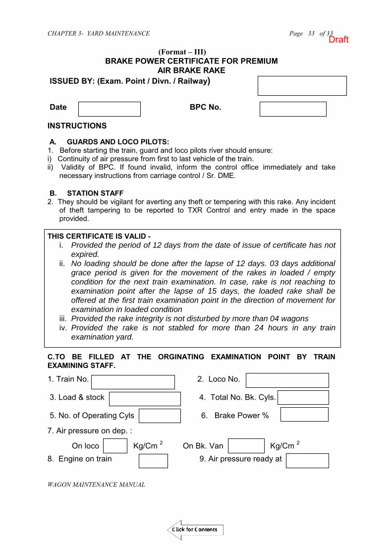
CHAPTER 3- YARD MAINTENANCE Page 33 of 33
WAGON MAINTENANCE MANUAL
33
(Format – III) BRAKE POWER CERTIFICATE FOR PREMIUM
AIR BRAKE RAKE ISSUED BY: (Exam. Point / Divn. / Railway)
Date BPC No. INSTRUCTIONS A. GUARDS AND LOCO PILOTS: 1. Before starting the train, guard and loco pilots river should ensure: i) Continuity of air pressure from first to last vehicle of the train. ii) Validity of BPC. If found invalid, inform the control office immediately and take
necessary instructions from carriage control / Sr. DME. B. STATION STAFF 2. They should be vigilant for averting any theft or tempering with this rake. Any incident
of theft tampering to be reported to TXR Control and entry made in the space provided.
THIS CERTIFICATE IS VALID -
i. Provided the period of 12 days from the date of issue of certificate has not expired.
ii. No loading should be done after the lapse of 12 days. 03 days additional grace period is given for the movement of the rakes in loaded / empty condition for the next train examination. In case, rake is not reaching to examination point after the lapse of 15 days, the loaded rake shall be offered at the first train examination point in the direction of movement for examination in loaded condition
iii. Provided the rake integrity is not disturbed by more than 04 wagons iv. Provided the rake is not stabled for more than 24 hours in any train
examination yard.
C. TO BE FILLED AT THE ORGINATING EXAMINATION POINT BY TRAIN EXAMINING STAFF.
1. Train No. 2. Loco No. 3. Load & stock 4. Total No. Bk. Cyls. 5. No. of Operating Cyls 6. Brake Power % 7. Air pressure on dep. : On loco Kg/Cm 2 On Bk. Van Kg/Cm 2
8. Engine on train 9. Air pressure ready at
Draft

CHAPTER 3- YARD MAINTENANCE Page 34 of 33
WAGON MAINTENANCE MANUAL
34
LIST OF WAGONS IN ORDER S.No WAGON No. S.No. WAGON No. S.No. WAGON No.
1 21 41
2 22 42
3 23 43
4 24 44
5 25 45
6 26 46
7 27 47
8 28 48
9 29 49
10 30 50
11 31 51
12 32 52
13 33 53
14 34 54
15 35 55
16 36 56
17 37 57
18 38 58
19 39 59
20 40 60
LOCO PILOTS NAME & SIGN
GUARDS‟S NAME & SIGN
SE/JE (C&W) NAME & SIGN
Draft

CHAPTER 3- YARD MAINTENANCE Page 35 of 33
WAGON MAINTENANCE MANUAL
35
D. DISTANCE TRAVELLED (TO BE FILLED BY LOCO PILOTS) S. No.
DATE LOCO No.
TRAIN No.
LOCO PILOTS NAME/HQ
FROM TO KMS. CUM KMS.
LOCO PILOT‟S
SIGN
Draft
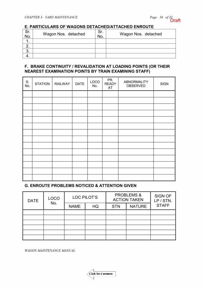
CHAPTER 3- YARD MAINTENANCE Page 36 of 33
WAGON MAINTENANCE MANUAL
36
E. PARTICULARS OF WAGONS DETACHED/ATTACHED ENROUTE Sr. No. Wagon Nos. detached Sr.
No. Wagon Nos. detached
1. 2. 3. 4.
F. BRAKE CONTINUITY / REVALIDATION AT LOADING POINTS (OR THEIR NEAREST EXAMINATION POINTS BY TRAIN EXAMINING STAFF)
S. No. STATION RAILWAY DATE LOCO
No.
PR. READY
AT
ABNORMALITY OBSERVED SIGN
G. ENROUTE PROBLEMS NOTICED & ATTENTION GIVEN
DATE LOCO No.
LOC PILOT’S PROBLEMS & ACTION TAKEN
SIGN OF LP / STN.
STAFF NAME HQ STN NATURE
Draft

CHAPTER 3- YARD MAINTENANCE Page 37 of 37
WAGON MAINTENANCE MANUAL
TABLE 3.3
DISTRIBUTION OF INTENSIVE STAFF, GANG WISE WITH TOOLS AND MATERIAL TO CARRY S.
No. Gang Tools Material to carry Items to be examined/Repaired
( Air Brake ) 1
“A” having 2 Sk +2U/Sk
Hammer 2, Monkey spanner Chisel 1, Spanner 2 (3/8”X 7/16” & 2”X ½”)
MU washer /BP hose-2, MS bolts 2X1/2, Knuckle pin-4, Dummy plug-2 (spare)
CBC & its components, setting of CBC lock piece with toggle, knuckle pin, Brake pipe & BP air hose, MU washer, angle cock, Isolating cock.
2 “B” having 3Sk+ 3U/Sk
Hammer 3, Chisel 2 Round Punch 2, Spanner 2 (3/8”X 7/16”
Brake block, Brake gear pins, Brake gear cotter No.5,6&7. Split pins 2-1/2”X1/4”, 3-1/2”X5/16”, 4”X3/8” Brake shoe key, washers (Plain & spring) , other type of split pins
Brake blocks, brake shoe key, split pin, washer, cotter and brake shoe key safety fittings, APD, Brake beam safety bracket, safety loops, bolts, SAB safety bracket, Pull rod safety bracket, tyre defect gauge
3
“C” having 1Sk+ 2U/Sk
Hand Hammer 1, Chisel 1 Spanners 1/2”X 3/8”, 5/8”X 3/4” 3/8”X 7/16” 1/4”X 5/16”
Guard van valve with diaphragm. Distributor valve, piston stroke, Brake power by testing the rake with air compressor and testing rig.
4. “D” having 3Sk +3U/Sk
Hand Hammer 3, Chisel 3 Punch Round 3 Punch cotter 3 Ring spanner 2, Plain spanner2 1/2X5/8” and 3/4X7/8”
Buffer bolts 3-1/2X3/4”, spring washer,. EM pad, bolster spring, snubber spring, adopter, side frame key, side bearer, Centre pivot top, Centre pivot pin.
5. “E” having 1Sk +2U/Sk
Hand Hammer 2 Spanner 1/2X3/8 -1
----- Axle boxes, Rolling in examination, work with “C” gang for Testing brake power and other Misc. work.
Draft

CHAPTER 3- YARD MAINTENANCE Page 38 of 37
WAGON MAINTENANCE MANUAL
TABLE 3.4 WARRANTY PERIOD OF VARIOUS FREIGHT STOCK ITEMS
SNo. Description Warranty Period Reference
1. New Wagons 24 Months from the date of commissioning. Rly. Board‟s lettee No. 2006/RS(!) /954/31/1566 dated 27.10. 06 2. CTRB 48 Months from the date of supply or
36 Months from the date of commissioning. RDSO‟s STR No. AB/RB-39 (Rev.-3) Amendment No. 2
3. Adapters 48 Months from the date of supply or 36 Months from the date of commissioning.
RDSO‟s STR No. AB/RB-39 (Rev.-3) Amendment No. 2
4. BP Hoses 36 Months from the date of supply or 24 Months from the date of commissioning.
RDSO‟s Specification No. 02-ABR-02
5. Brake Cylinder 36 Months from the date of supply or 24 Months from the date of commissioning.
RDSO‟s Specification No. 02-ABR-02
6. SAB 36 Months from the date of supply or 24 Months from the date of commissioning.
RDSO‟s Specification No. 02-ABR-02
7. CC Pads 30 Months from the date of supply. RDSO‟s STR No. WD-03-Misc-86 (Rev-3) ) Amendment No. 3 8. PU Side Bearers 30 Months from the date of supply. RDSO‟s Specification No.WD-38-Misc-2004 (Rev-1) ) 9. EM Pads 30 Months from the date of supply. RDSO‟s Specification No.WD-20-Misc-95 (Rev-3) ) 10 CBC Coupler, Yoke,
Knuckle 54 Months from the date of supply or 42 Months from the date of commissioning.
RDSO‟s STR No. 48-BD-08
11. Draft Gear 54 Months from the date of supply or 42 Months from the date of commissioning.
RDSO‟s STR No. 48-BD-08
12 Distributor Valve 36 Months from the date of supply or 24 Months from the date of commissioning.
RDSO‟s Specification No. 02-ABR-02
13 Angle Cock 36 Months from the date of supply or 24 Months from the date of commissioning.
RDSO‟s Specification No. 02-ABR-02
14. Composite Brake Block 18 Months from the date of supply. RDSO‟s Specification No. WD-13-ABR-2006
Draft

CHAPTER 4 - WAGON BODY Page 1 of 28
WAGON MAINTENANCE MANUAL
(WAGON MAINTENANCE MANUAL- 2013)
CHAPTER - 4
WAGON BODY
Draft
Click for Contents

CHAPTER 4 - WAGON BODY Page 2 of 28
WAGON MAINTENANCE MANUAL
CHAPTER 4
WAGON BODY
401. INTRODUCTION The superstructure attached to the underframe of a wagon is called wagon body. It
consists of body side and ends with their supporting structures such as stanchions, copings, roof structures, carlines; roof sheets in the case of covered wagons; hoppers and their supporting members in case of hopper wagons; tank barrels, cladding, if any, and supporting saddles in the case of tank wagons. Doors, door fittings, louvers for ventilation and various fittings such as cleats, handles, hooks, footsteps, hand brake wheel and ladders also form part of the body.
This chapter is concerned with the body or superstructure of general purpose open and covered wagons, hopper wagons, bogie flat wagons including container wagons and military wagons. The Superstructure and fittings of tank wagons are dealt with separately in the Chapter 10 on Tank wagon.
402. GENERAL CONSTRUCTION OF OPEN WAGON
A. SIDES
Sides are made up of side panels and side stanchions, which are attached to the underframe by crib angles, riveting strips and side stanchions. They include top copings, intermediate copings if any, doors, door fittings, hand holds, tarpaulin cleats and label holders.
B. ENDS
Ends are similar in construction to sides in that they consist of end panels, end stanchions, top copings and in some cases end shut stiffener, ventilator and intermediate copings. Attachment to the underframe is by means of end floor angles and through the stanchions. Corner stanchions connect the ends with the sides. Open wagons have reinforcing angles at each end together with reinforcing gussets and corner pressings at the corner.
C. DOORS
Each side of the wagon is provided with door for manual unloading. The doors are hinged at the bottom with locking arrangement by chainless cotter at the top. In BOXN wagons two extra locking bolts per door have also been provided to avoid slipping of chainless cotter during tippling of wagon.
403. GENERAL CONSTRUCTION OF COVERED WAGON
A. SIDES
Sides are made up of side panels and side stanchions, which are attached to the underframe by crib angles / riveting strips /welding strips. They include top
Draft

CHAPTER 4 - WAGON BODY Page 3 of 28
WAGON MAINTENANCE MANUAL
copings, doors, door fittings, label holders, rain protection angles above swing doors, door striking plates and anti bleeding device below the flap doors.
B. ENDS
Ends are similar in construction to sides in that they consist of end panels, end stanchions, top copings and in some cases, intermediate copings. Attachment to the underframe is by means of end floor angles and through the stanchions. Covered wagons are provided with ventilators at the upper end of body ends. Corner stanchions connect the ends with the sides.
C. ROOF
Roofs of covered wagons consist of roof sheets and carlines. Roof sheets are much thinner than the sheets used for the body sides and end panels.
D. DOOR
Each side of the wagon is provided with door for manual unloading. The doors consist of swing doors at the top with label holder hinged to the angles on the sides and flap doors at the bottom, hinged at the bottom with Anti bleeding device.
404. GENERAL CONSTRUCTION OF FLAT WAGON AND WELL WAGON
A. ENDS
Flat/well wagons do not have side wall and roof. The superstructure consists of either fixed or flexible ends. These are fixed to the underframe through stanchions, side attachment plates and crib angle.
B. SIDE STANCHION
Flexible side stanchions are attached to the sole bar through brackets. In addition, support brackets are also provided in rail wagons and well wagon. In container flat wagons, retractable anchoring locks are provided.
405. GENERAL CONSTRUCTION OF HOPPER WAGON
A. SIDES
Sides are made up of side panels and side stanchions, which are attached to the underframe. They include top copings, side stiffeners, doors in side discharge wagons, and label holders.
B. ENDS
Ends consist of end panels, end stanchions, end top copings and in some cases, stiffeners. Attachment to the underframe is through the stanchions. Corner stanchions connect the ends with the sides.
C. DOOR AND DOOR OPERATING MECHANISM
Hopper wagons are provided with either side discharge/centre discharge doors or both. Door operating mechanism is generally manually operated by means of bevel wheel and worm wheel connected to door operating hand wheel. In some
Draft
CHAPTER 4 - WAGON BODY Page 4 of 28
WAGON MAINTENANCE MANUAL
special type of hopper wagons like BOBRN, pneumatically operated door operating mechanism has been provided.
406. NATURE OF REPAIRS REQUIRED IN WAGON BODY
Apart from wagons involved in accidents or other serious mishaps, attention is normally necessitated because of the following defects:-
i. Corrosion of panels, floor plates and roof sheets. ii. Puncturing of panels due to improper loading, inadequately secured
consignments or deliberate tampering. iii. Bulging of ends due to shifting of loads. iv. Tearing of panels, fracture of stanchions and shearing of rivets due to severe
impacts, and shifting of loads. v. Corrosion of end floor angles and crib angles. vi. Bulging of side usually occur after a prolonged period in service. vii. Slackening of rivets due to the combined effect of ageing, corrosion, wear and
tear. viii. Weakening of welded joints due to loss of weld metal by corrosion, wear and
tear. ix. Wearing out of door hinges. x. Damage to door fittings because of wear and tear or mishandling. xi. Distortion of doors mainly because of mishandling. xii. Failure of welded joints. xiii. Distortion or cracking of stanchions and other structural members because of
abnormal loads, e.g., those due to defective clamping on tipplers. xiv. Wear and tear or breakage of miscellaneous fittings, such as ladders, cleats, label
holders etc. xv. Damages due to mechanised loading/ unloading (Payloaders/ Tipplers)
407. CORROSION IN WAGON BODY The corrosion of wagon floor and roof plates results from:
i. Water logging in crevices and overlaps. This is greatly accentuated if cleaning is neglected, since the accumulated dust and refuse retain moisture for a prolonged period.
ii. Contact of panels with residues from corrosive consignments e.g., salt, fertilizers etc.
iii. Spillage of corrosive fluids due to defective packing or rough handling. iv. Escape of corrosive vapours from the consignment. v. Inadequate protection from weathering because of poor painting or inadequate
surface preparation. vi. The current practice is to paint only the exterior of the wagon body and not the
interior, except for inside panels up to a height of 230 mm from floor, rivet seams and in the case of covered wagons, the swing and flap doors and the roof. The interior is left largely unpainted because paints have hitherto not been available which could withstand the constant scrubbing action of the consignment against the wagon walls. It is nevertheless a fact that most of the time corrosion originates from the interior of a wagon rather than the exterior.
Draft

CHAPTER 4 - WAGON BODY Page 5 of 28
WAGON MAINTENANCE MANUAL
408. ANTICORROSIVE MEASURES
i. The most important anti corrosive measure to be taken in day to day working is to ensure that the wagon is kept thoroughly clean and receives special attention in this respect after it has transported a corrosive or hygroscope commodity.
ii. The second important step to prevent corrosion is to ensure that cleaning, surface preparation and painting are carried out with due thoroughness. The correct procedure to be followed in major maintenance schedules is given at the end of this chapter. The procedure to be adopted at the time of minor repairs should come as close to this as practicable.
iii. While attending to miscellaneous repairs, panel patching or welding; it is important to ensure that surfaces in contact are well fitted to avoid water pockets. Due care is to be taken to clean and paint the affected surfaces to prevent corrosion by electrochemical action.
iv. Use of Stainless Steel (IRS: M44) has been started in wagon rehabilitation/ new manufacture. This material has much better corrosion resistance.
409. REJECTABLE DEFECTS The inspection of wagon body is to be carried out in sicklines and workshops as per
procedure laid down in IRCA Part-III Rule 4.2 & 4.7. 410. REPAIRS IN SICKLINE & ROH DEPOT
410A PANEL PATCHING
The bottoms of body side and end sheets are particularly vulnerable to destruction by corrosion and also puncturing by miscreants. If the area to be patched extends beyond 260mm from the floor height, either two standard patches of 5 mm thickness should be used one above the other or a single special patch of 5 mm thickness and a width of 520 mm should be used. In case two or more adjacent panels require patching at a time, the complete length of corrosion can be covered by a special patch, which must, however, extend from stanchion to stanchion, as shown in figure 4.1. The standard panel patches for BOXN wagons are given in Table- 4.1. For detailed instructions of panel patching for BOXN wagon RDSO Drg. No. WD-94047-S-1 may be referred. In case of BCN/BCNA wagons, the thickness of plate should be 3.15 mm for end & sides and 1.6 mm for roof and the sizes depends on affected area to be covered for repair.
Draft

CHAPTER 4 - WAGON BODY Page 6 of 28
WAGON MAINTENANCE MANUAL
CRIB ANGLE
CUT ALONG THIS EDGE
EXISTING PANEL
FIG 4.2
FIG 4.1
CORNER STANCHION
SPECIAL PATCH PLATE
STANCHION
FIG 4.3
FIG 4.4
PATCH PLATE
STANCHION
PACKING13
EXISTING PANEL
HEAD STOCK
CUT ALONG THIS EDGE
END FLOOR ANGLE
Draft

CHAPTER 4 - WAGON BODY Page 7 of 28
WAGON MAINTENANCE MANUAL
TABLE- 4.1 PANEL PATCHES FOR BOXN WAGON
S. No
Width (mm) Plate length (mm)
Plate thickness
(mm)
Material specification Step size
A Step size
B Step size
C 1. 300 610 1275 552 5 IRS M-41 2. 300 610 - 552 5 " 3. 300 680 - 1470 5 " 4. 300 680 - 1445 5 " 5. 300 525 1170 1445 5 " 6. 315 - - 1470 5 " 7. 300 600 850 445 5 " 8. 820 - - 445 5 " 9. 300 600 850 555 5 " 10. 820 - - 555 5 " 11. 300 600 850 700 5 " 12. 820 - - 700 5 "
i. For locations other than the skirting plates, damaged panels should be replaced
by using standard patches. These patches should invariably be of the same thickness as the damaged panel.
ii. Sick lines may weld or rivet smaller patches to take care of minor damages, but in no case, should a patch of less than 100mm on any one side be used. If the patch is attached by riveting there should not be less than 8 rivets securing the patch. The pitch of the rivets must also not exceed 90 mm.
iii. Standard patch plates should, preferably be kept ready in stock in shops and sicklines after proper surface cleaning and painting with two coats of zinc chromate primer.
410B. PROCEDURE FOR WELDED PATCHES
i. Examine and mark the area of patch to be cut. Cut the corroded panel along crib/end floor angle and up to a height suitable for standard patches, as shown in Fig. 4.2 and 4.3. The 2.5 mm thick old panel sheet at the stanchion should be retained as a packing piece if not badly corroded. Otherwise use fresh 5 mm thick packing (RDSO Drawing No. WD-94047-S-1). The packing should extend 13mm wherever lap welding of the new patch with packing piece is involved (See Fig. 4.4).
ii. Cut rivets on stanchion as required and end floor angle horizontal leg by 10 mm
when fitting patches at the corners as shown in Fig.4.5. Take a standard patch plate from stock or prepare the same from plate of requisite thickness.
iii. Cut floor plates by 8mm for fitting new patch, as shown in Fig. 4.5. As an
alternative, the patch plate may be made to rest over the floor plate, as shown in Fig. 4.6 & 4.7. In case, floor plates also require renewal, the width of the floor plates should be reduced to follow the arrangement shown in Fig. 4.8 & and 4.9.
Draft

CHAPTER 4 - WAGON BODY Page 8 of 28
WAGON MAINTENANCE MANUAL
Secure the standard patch on the wagon by means of tack welding. Weld all around.
iv. Rivet 2.5mm packing piece in position as shown in Fig. 4.10. v. Overlapping portions should be welded on both sides as shown in Fig. 4.11 and
4.12. vi. Ensure continuous welding without any craters. vii. In case of bulged panels, the patch should be riveted to the panels, as shown in
Fig. 4.13. viii. Clean and repaint the welded portion at locations where paint has been burnt off.
Draft

CHAPTER 4 - WAGON BODY Page 9 of 28
WAGON MAINTENANCE MANUAL
END FLOOR ANGLE
CUT HERE
CORNER STANCHION 10
FIG. 4.5
FIG. 4.6
FLOOR PLATE
CRIB ANGLE
PATCH PLATE
FIG. 4.7
WELD
WELD
FLOOR PLATE
PATCH PLATE
CRIB ANGLE
FIG. 4.8
CRIB ANGLE
FLOOR PLATE
PORTION OF FLOOR PLATE TO BE CUT OR REDUCED 8
WELD
WELD
PATCH PLATE
FIG. 4.9
CRIB ANGLE
FLOOR PLATE
Draft

CHAPTER 4 - WAGON BODY Page 10 of 28
WAGON MAINTENANCE MANUAL
FIG 4.10
PACKING
STANCHION
PATCH PLATE
FIG 4.12
EXISTING PANEL WELD
PATCH PLATEWELD
FIG 4.13
EXISTING PANEL
PATCH PLATE
10 DIA RIVET
PATCH PLATE WELD
WELD
PACKING STANCHION
FIG 4.11
Draft

CHAPTER 4 - WAGON BODY Page 11 of 28
WAGON MAINTENANCE MANUAL
410C. RIVETED PATCH Riveted patch should be avoided in workshops. These can however be applied in
sickliness and ROH depots as per following procedure.
i. Examine and mark the area of the patch to be cut. ii. Take a standard patch plate from stock or prepare the same from plate of
requisite thickness. iii. Position the patch on the wagon and mark the location of the rivet holes. iv. Drill/punch the holes on both the patch and the wagon panel and secure the latter
in position by temporary bolts and nuts. v. Rivet the patch in position. vi. Ensure that riveting is sound and with concentric snap heads, and also that
mating edges are set properly leaving no gap in between.
410D. REPAIRS TO BULGED ENDS If there are no serious damages to wagon ends other than bulging, the bulges can be effectively removed without dismantling. If two wagons with bulged ends are coupled together and a hydraulic jack is applied between them at the bulges, suitable packing being interposed between the jack and the wagon body. This method is particularly effective in dealing with dread-naught ends.
410E. REPAIRS TO BODY STRUCTURAL MEMBERS (STANCHIONS, CARLINES AND COPINGS) a. Damages to these members are usually due to rough handling, heavy shunting
impacts or shifting of loads due to improper packing/stacking of the consignments. At first these components bulge out, but later even the rivets holding them to the underframe/superstructure members break out. It should be ensured that the bulging of these components does not cause infringements with the maximum moving dimensions. Bulging of these components by more than 25mm should be rectified. These components should be straightened without dismantling by pulling into correct position with the help of a chain and screw coupling or stripped and straightened either cold or by heating, as required and then riveted in position. Spot heating and cooling to straighten the stanchions can rectify bulging of all welded ends.
b. In certain cases, these components may have developed cracks, or may have broken in pieces. Such of these components should be repaired by welding both the pieces and applying a stiffener angle prepared by bending a 6mm plate in the shape of an angle with its outer faces sitting flush in the inner profile of the member to be patched and welding it all round to the member. Elongated holes in these components should be filled up by welding and refilled.
410F. WATER TIGHTENING OF WAGON Covered wagons must be kept watertight at all times. Covered wagons must be tested for water tightness at the time of leaving the workshop after POH or other repairs. All empty covered wagons attended to in sicklines, should also be tested for leaks, and made watertight by applying sealing compound before the onset of the monsoon season, a special drive should be instituted and sealing compound must be applied at
Draft

CHAPTER 4 - WAGON BODY Page 12 of 28
WAGON MAINTENANCE MANUAL
all points of covered wagon bodies, which are likely to leak particularly peripheries of riveted patches other overlaps and small holes. Before the application of sealing compound, mechanical defects such as bulged panels severely distorted body structural members, gaping joints, loose rivets and other corroded areas must be attended to. It should be ensured that the surfaces are clean and dry before sealing compound is applied. An attempt must not be made to fill up large gaps or other openings with sealing compound. Holes more than 6 mm in diameter should be filled by rivets. Irregular openings and cuts with more than 25 mm length and 3 mm width should be repaired by patching or welding. After a wagon has been made watertight, it should be marked “WT” with station code and date on the left-hand bottom corner of both sides.
410G. REPAIRS TO DOORS AND DOOR FITTINGS (FOR MILD STEEL WAGONS)
The main defects arising in doors are:-
Distortion due to wedging or other mishandling Jamming of hinges Excessive clearances in hinges Inadequate overlap between flaps and door leaves Gaping of doors at the stanchions Distortion or breakage of tower bolts Breakage of hinges and Damage to gravity cotters, hooks and hasps.
Damaged doors of covered wagons are responsible for a very large proportion of claims due to wetting or pilferage of consignments. Warpage of flap doors is often responsible for jamming of flap door hinges. Special care must therefore, be taken in attending to doors.
Distorted or bulged doors must be taken down and straightened to ensure proper fit. Worn out hinges are responsible for sagging or gaping doors and inadequate overlap. Such hinges must be replaced with new or reconditioned ones.
Bent door stanchions and depressed crib angles must be straightened to ensure free functioning of doors and prevent gaping. Corroded crib angles must be cut out and replaced. Graphite grease should be introduced in all hinges, sliding cotters and other working parts.
After repairs, doors must sit flush against striking plates with adequate overlap between leaves and without gaping at the stanchions or crib angles. Anti-bleeding devices and rain protection angles should also be checked and rectified where necessary.
In the case of hopper wagons, it should be ensured that when the doors are
closed, no gap is left between the chute plate and frame, and that the operating gear works freely and is in good condition.
Draft

CHAPTER 4 - WAGON BODY Page 13 of 28
WAGON MAINTENANCE MANUAL
410H. REPAIRS TO DOORS AND DOOR FITTINGS (FOR BCNHL WAGONS) BCNHL wagons have been fitted with doors which are different from conventional BCN doors. The first original design was initiated in May-2008, but some problems/defects were observed by the Zonal railways in field during loading unloading. The original(first) design is given in photo-1.0
BCNHL with BCNA
door
BCNHL Door designs:Original (First) Design (May’2008)
Photo -1.0
Draft

CHAPTER 4 - WAGON BODY Page 14 of 28
WAGON MAINTENANCE MANUAL
MMD &
BCNHL
Observing problems in the field, design Modification-I was done in June-2009 vide RDSO drawing No. WD5-SRD-S-01 & S-02 and existing design was modified to eliminate gap between side wall and door at hinge, improving door securing & hence eliminating the possibility of door hitting & rain water seepage. See photo-2.0
Design Modification-I (June’2009)Existing Design modified by improving securing of doors
(Drg. No. WD5-STD-S-1 & S-02)
Chainless cotter
Door catch
• Modification to eliminate gap between side wall and door athinge, improving door securing & hence eliminating thepossibility of door hitting & rain water seepage.
Photo-2.0 Further after gaining experience, design modification-II was incorporated in june-2010 by providing tower-bolt on out side in place of inside the door. In this modification, small chainless cotter, (02 nos.) on outside were provided in place of existing long chainless cotters. See photo-03
Draft
Click for Contents

CHAPTER 4 - WAGON BODY Page 15 of 28
WAGON MAINTENANCE MANUAL
Design Modification-II (June’2010)• Provision of small chainless cotter, ( 2 nos.) on outside, in place of existing long chainless cotters. • Provision of Tower-Bolt on outside (instead of inside door).
latch
Swing bolt with doublehasp
Chainless cotter
Inner view of additional door locking arrangement
Outer view of door locking arrangement
Hinged Door- Modification-II-(Current, latest Design of Hinge Door).
Photo- 3.0
B. Some other Door designs used in limited numbers on the wagons 1. Design alteration (Pressed Door Design-4 hinges)-Variant-II was developed by
RDSO in June-2009. See photo-04
Draft
Click for Contents

CHAPTER 4 - WAGON BODY Page 16 of 28
WAGON MAINTENANCE MANUAL
Photo -4.0
2. Sliding door (Fabricated design) Bottom Roller design was developed by RDSO in August-2009 and was provided on trial on limited no. of wagons. See photo-05
Photo -5.0 3. Sliding door ( Pressed design) Top mounted Rollers on Guide channel was
developed in April-2010 and was provided on the wagons on trial basis. See photo-06
Photo -6.0
Design Iteration ( Pressed Door design- 4 hinges)-Variant-II (June’2009)
Sliding door (Fabricated design): Bottom roller design (Aug’2009)
Sliding door (Pressed design): Top mounted Roller on Guide Channel (Apr’2010)
Draft

CHAPTER 4 - WAGON BODY Page 17 of 28
WAGON MAINTENANCE MANUAL
C. BCNHL POPULATION DISPERSION ( IN TERMS OF TYPE OF DOORS USED) (Till the Rly Board Contract of -2012). See table below
D. NEED OF DOOR MODIFICATIONS BY RDSO Owing to severe Field issues in earlier versions(Original and Mod-I), Zonal Railways have already been advised to undertake retro fitment of modified locking arrangement (As per Mod-II) in the earlier versions of door assemblies. For above retro fitment, RDSO has issued procedure and drawing No. WD-10036-S-01/WD-06076-S-13 in June-2010.
Draft

CHAPTER 4 - WAGON BODY Page 18 of 28
WAGON MAINTENANCE MANUAL
E. PROVISION OF MODIFIED DOORS IN NEW BCNHL WAGONS From amongst the designs tried in the field, the door design with top mounted rollers ( 300 Wagons) have performed with the least field problems. This door design with modifications to address all field issues has been standardised for new BCNHL wagons. See Photo-07
Photo -07
F. DESIGN MODIFICATIONS IN SINGLE P IECE PRESSED SLIDING DOOR (BCNHL DESIGN-D WAGONS). (a) Roller Support Bracket:
The Roller support bracket, welding has been strengthened.
(b) Roller Design & associated changes in guide channel: b.1 The roller diameter increased to in order to ensure a roller overlap (with the guide channel) of 12mm in place of the existing 8 mm.
b.2 The roller profile be modified from a flat profile to a convex profile, so that the existing line contact of the roller-guide channel , be modified to a point contact, to ensure smoother sliding motion of the door.
b.3 The number & location of rollers be modified from the existing three rollers, equidistant along the door width to FOUR rollers, with two rollers each in the front & end of the door width.
(c) Rain Protector Strengthening: The thickness of the rain protector channel be modified from the existing 2.5mm to 4mm. In order to provide support, additional ribs be provided, in the rain protector member.
Draft
Click for Contents

CHAPTER 4 - WAGON BODY Page 19 of 28
WAGON MAINTENANCE MANUAL
(d) Provision of additional lateral stop member: In order to prevent a lateral falling/ movement of door sheet, an additional lateral stop member, needs to be provided.
(e) Support in Bottom guide: To prevent blockage of the bottom guide owing to loose cement, a continuous slot has been provided. In order to provide strength to the bottom support, strengthening of the support be done by providing ribs at a pitch of 180mm between the auxiliary sole bar & the vertical face of the inside sole bar channel.
(f) Back Sheet on door: The pressed impression on the door, results in a cavity that could lock/entangle loaded commodity bags, during the sliding motion of the door. To prevent the above, the depressed cavity be covered using off-cuts of the 1.6mm thick sheet. Sections of suitable sizes of this sheet (1.6mm thick) be welded on the inside of the pressed door sheet to cover the portion of the pressing & ensure a smooth door surface on the inside.
(g) Strengthening the Bottom part of door sheet:
During service in the field, the bottom part of the door, is reported to working-out from the provided slot. To strengthen the bottom portion of the door & to prevent its working out, a 6mm flat be welded at the bottom portion of the door sheet.
Draft
Click for Contents

CHAPTER 4 - WAGON BODY Page 20 of 28
WAGON MAINTENANCE MANUAL
G. RETROFITABLE SLIDING DOOR FOR OLDER BCNHL WAGONS For older BCNHL wagons (manufactured prior to June’2010), & NECESSARILY warranting door replacements, a retrofitable two-part door design has been developed.
Highlights of the Retrofitable sliding door design:
2 Part Sliding Door. Sliding using 3 sets of rollers (on each door ) mounted on top portion of door. Door Supported at Bottom. Top pivoted door with ability to move laterally (on being pushed by loaded
bags). Retrofitable design. Can be fabricated as a unit & be mounted on existing
BCNHL wagons.
Retrofit-able Sliding Door
Retrofit-able Sliding Door
Draft

CHAPTER 4 - WAGON BODY Page 21 of 28
WAGON MAINTENANCE MANUAL
Lower Weight (75 kgs of each door vs 105 kgs of Hinge door). No chances of hitting any fixed structure, since lateral projection less than side
stanchions. Secured locking arrangement, easily operational from non-platform line. Ease of Loading/ Unloading owing to Sliding Door design. Ease of Maintenance- rollers fitted in guide channel, with end covers which
can be replaced/ opened easily. Brgs in Rollers provided with dust cover & concealed to prevent ingress of
dirt. To facilitate lateral movement transfer balls provided at door bottom.
410I. CLEANING, SURFACE PREPARATION AND PAINTING
The correct sequence and procedure for cleaning, preparation of metal surfaces to be painted and the painting thereof;
a. Preparation of surface before painting
The purpose of cleaning is to remove dirt, oil, grease, rust and other contaminants, which would prevent the paint film from adhering to the metal or would provide a nucleus for commencement of corrosion.
Cleaning by hammering, chiselling or scraping is unsatisfactory and should not be resorted to. The surface cleaning may be done by vigorously scrubbing with a stiff brush. All welded parts and adjacent surfaces should be thoroughly cleaned to remove residual alkaline flux and washed with hot water.
b. A coat of priming paint should be applied immediately after the surface has
been cleaned and dried. A delay of more than 4 hours may result in development of fresh rust on the surface. A second coat of primer must be given when the first coat is dry. Painting must be done under cover in a shed or shop. The painted surfaces must remain under cover until the paint is dry.
c. Panel patches and riveting strips must be cleaned, as prescribed above, and given two coats of primer before storage or fitment.
d. After completion of all repairs a final coat of finishing paint should be given to all painted surfaces.
e. When the paint film is only partially damaged, it should be touched up with one coat of primer and then given the finishing coat.
f. Surfaces, which will become inaccessible after assembly must be given
complete painting before assembly.
Draft
CHAPTER 4 - WAGON BODY Page 22 of 28
WAGON MAINTENANCE MANUAL
411. REPAIRS AND MAINTENANCE IN WORKSHOPS DURING POH AND NPOH
a. For body repairs, same procedure as described in para 410 A to 410 I above is to be followed.
Note :- The detailed procedure for painting and specifications for different coats of paint are given in general standard specification G-72 read with latest amendments which may be referred to for more details.
In addition to the above, following items to be carried out during POH in workshops.
b. Lettering
Lettering to be carried out as per IRCA Part III Rule 2.4 by stencilling the relevant figures.
c. Punching of wagon particulars. d. PR plate e. Tare weight to be measured after POH and it should be marked up to one
decimal. 412. IMPORTANT PRECAUTIONS TO BE TAKEN WHILE CARRYING
OUT WELDING
Welding entails the risk of fire if combustible materials are present near the area being welded. To prevent such accidents, the following precautions must be taken:
A. Loaded wagons
It should be ensured that the content is not inflammable. Should the contents be inflammable they must be transhipped before welding is attempted.
Tank wagons should never be welded when loaded.
B. Empty wagons
It should first be ensured that no portion of an inflammable consignment packing material or dunnage is present in the area to be welded. Empty tank wagons should be given welding repairs only in depots specially equipped for this purpose and only after thorough steam cleaning and testing to ensure that there are no inflammable/explosive vapours left.
C. Wagons fitted with CTRBs
No welding should be attempted without effectively earthing the member or component to be welded. Neglect in taking this precaution will result in passage of the return current through the CTRB, which may suffer severe damage leading to premature failure.
Draft
CHAPTER 4 - WAGON BODY Page 23 of 28
WAGON MAINTENANCE MANUAL
413. IMPORTANT DO'S AND DON'TS
Do's i. Ensure that you have the proper tools required for the job. Use of improper tools
can make matters worse.
ii. Ensure that tools and equipment are in good condition.
iii. See that rivet heads are properly formed with correctly profiled snaps. iv. While fitting patches to structural members, ensure that the pitch of rivets
conforms to the original pitch in the structural members. v. See that doors are provided with all required fittings so as to ensure proper
securing and prevent unauthorised opening. vi. Ensure that door hooks are intact and so placed that they will engage with the
door eye in open position. vii. Ensure that all chains links and other attachments are in position and in working
order. Don’ts
i. Do not use patches of less thickness than the original panel. ii. Do not patch existing patches. iii. Do not build up perforations in panel due to corrosion. Cut out and fit a new
patch. iv. Do not permit empty wagons to run with open doors. v. Do not permit loaded wagons to run without properly secured doors. vi. Do not allow wagons with inadequately secured/lashed consignments.
414 MAINTENANCE OF STAINLESS STEEL WAGONS The Maintenance of Stainless Steel Wagons is covered in APPENDIX-VI
415 UPGRADED REHABILITATION OF BOXN TO BOXNR
Vide Rly. Board’s letter no. 2005/ M (N)/204/2 (RSP) dated 02.11.07 it has been decided that rehabilitation of BOXN wagons would be done to BOXNR design (stainless steel body). The constructional differences between BOXN & BOXNR are as follows:
Draft

CHAPTER 4 - WAGON BODY Page 24 of 28
WAGON MAINTENANCE MANUAL
A. TECHNICAL REQUIREMENTS FOR UPGRADED REHABILITATION OF BOXN WAGONS TO BOXNR SHALL BE DONE AS PER RDSO SPEC. NO. WD.16.BOXNR-2010 OR LATEST
After the rehabilitation and upgradation, the wagon shall be marked as BOXNR
in place of BOXN. The major differences in constructional features of BOXN & BOXNR are as under:
SIDE WALL
BOXN BOXNR (i) Material mild steel (i) Material stainless steel(IRS:M44) (ii) Provided with 6 Nos. of side
stanchions with 8mm thick hat section ( on one side)
(ii) Provided with 9 Nos. of side stanchions with 6mm thick CRF hat section (on one side)
(iii) Side sheets of 5mm thickness (iii) Side sheets of 3 mm thickness. (vi) Inside height of side wall is
1950mm from floor level. (iv) Inside height is 2127mm from floor
level. (v) Two Nos. middle coping
provided in sidewall. (v) Middle copings are not provided
in side walls, except at corner side panels.
(vi) Top coping provided with ISMC-100
(vi) Top coping provided with press section of BOX 100x100x6mm thick.
(vii) Side stanchion riveted with sole bar with two rows rivets.
(vii) Side stanchion huck bolted with sole bar with single row.
DOOR PLATE
(i) Door Plate provided with
Mild Steel for 5 mm thickness (i) Door plate provided with stainless
steel of 4 mm thickness.
END WALL
(i) Made with mild steel. (i) Made with stainless steel (IRS:M44) (ii) Each End wall provided with
4 Nos. of End stanchions of ISMC-150mm.
(ii) End wall provided Two side stanchion in three pieces and two middle coping of Hat section 6 mm thickness.
(iii) End top coping provided with ISMC-150 channel.
(iii) End top coping provided with CRF section of BOX 100x100x6mm thickness
(iv) End Sheet provided with 5 mm thick
(iv) End Sheet provided with 3 mm thick
FLOOR PLATE
(i)
Floor Plate provided with Mild Steel for 6 mm thickness
(i)
Floor plate provided with stainless steel of 4 mm thickness.
Draft

CHAPTER 4 - WAGON BODY Page 25 of 28
WAGON MAINTENANCE MANUAL
B. DESCRIPTION OF WORK:
The rehabilitation of BOXN wagon body by using of CRF section (to RDSO’s specification no. WD– 01 – CRF – 08 or latest) and stainless steel (IRS:M 44: 97 latest revision) will provide additional strength to body and reduce corrosion. The volume will also increase to fully utilize the capacity upto 22.9 Tonne axle load for coal.
Note: The procedure, precautions and facilities required for repairs to Stainless steel wagons will be similar to above upgradation.
416 LOCK BOLTS
Almost all new wagons specially stainless steel wagons are provided with lock bolting instead of riveting. In repair/maintenance CP top of all wagons irrespective of materials are to be lock bolted. entire lock bolting is to be done with zinc plated/galvanized lock bolts (grade-8) having a minimum yield strength of 250 N/mm2.
Lock Bolts have been introduced in the fabrication of Wagons. Lock bolt fasteners consist of Lock bolt pin and collar, and are installed with the help of special installation tools, as follows-
Lock bolt pin is placed in drilled hole, and collar is placed onto the lock bolt pin. Installation tool engages and pulls the lock bolts pin. Tool swages the collar onto lock bolt grooves. Pin tail breaks off the lock bolt pin.
The advantages of Lock bolts are – High strength Vibration resistant
Fast and easy installation Maintenance free
FIG. 4.14 LOCK BOLT
Draft

CHAPTER 4 - WAGON BODY Page 26 of 28
WAGON MAINTENANCE MANUAL
NOTE: The details of Lock Bolts and its equipments may be seen in Hand book on guidelines of Lock Bolt prepared by CAMTECH.
Proper Installation of lock bolts:- It should be ensured that:
(i) The collar of lock bolt are completely swaged. The collar of lock bolt fasteners not completely swaged may be causes of improper tool operation or worn anvil in nose.
(ii) The pintail of fastener break without fail. The pintail of fastener fails to break due to improper installation/incorrect fasteners.
(iii) After breaking of pintail, the extruded/projected portion of lock bolt should be in the range of 2.00 to 10 mm and collar should always be on annular groove of lock bolt.
(iv) Mismatch of holes to be reamed properly to align and gas cutting to match holes is strictly prohibited.
Draft

CHAPTER 4 - WAGON BODY Page 27 of 28
WAGON MAINTENANCE MANUAL
417 NEW WAGON NUMBERING SCHEME
Monitoring and liquidating overage arrears of rolling stock is a focus area in the interest of safety of train operations. However, some of the Railways have reported difficulty in ascertaining the age of wagons where the manufacturer’s plate is missing. Also computerization of wagon data is becoming cumbersome with development of various versions in a category e.g. BG bogie open wagons BOXN, BOXNHS, BOXNAHA, BOXNCR, BOXNHL, BOXNR and BOXNLW are being clubbed together by the computer cell and shown as BOXN in the holding. To overcome the above-mentioned problems and to facilitate computerization of the wagon data base, a new wagon numbering system was introduced by Railway Board as per letter no. 2000/M(N)/60/2/wagon census. Dated 4th July, 2003
In the new scheme, the wagon number shall consist of 11 digits as follows:
Type of wagon
Owning Railway
Year of Manufacture
Individual Wagon Number
Check Digit
C1 C2 C3 C4 C5 C6 C7 C8 C9 C10 C11
The codification for various types of wagons, owning railways, year of manufacture and individual wagon no. are as follows:
Type of Wagon Codes (C1, C2)
i) Open Wagon Code allotted 10 to 29 BOXN 10 BOXNHA 11 BOXNHS 12 BOXNCR 13 BOXNLW 14 BOXNB 15 BOXNF 16 BOXNG 17 BOY 18 BOST 19 BOXNAL 20
BOXN-HL 22
ii) Covered Wagon Code allotted 30 to 39 BCNA 30 BCNAHS 31 BCCNR 32 BCN-HL 33
iii)
Tank Wagon Code allotted 40 to 54 BTPN 40 BTPNHS 41 BTPGLN 42 BTALN 43 BTCS 44 BTPH 45 40 to 54 BTAP 46
Draft

CHAPTER 4 - WAGON BODY Page 28 of 28
WAGON MAINTENANCE MANUAL
iv) Flat Wagon Code allotted 55 to 69 BRNA 55 BRNAHS 56 BFNS 57 BOMN 58 BRSTH 59 BFAT 60 BLCA 61 BLCB 62
v) Hopper Wagon Code allotted 70 to 79
BOBYN 70 BOBYNHS 71 BOBRN 72 BOBRNHS 73 BOBRAL 74
vi) Well Wagon Code allotted 80 to 84
BWTB 80
vii) Brake Van Code allotted 85 to 89
BVZC 85 BVZI 86
OWNERSHIP (RAILWAYS’) CODES (C3, C4) :
SNo. Name of Railways Numerical codes 1 Central Railway 01 2 Eastern Railway 02 3 Northern Railway 03 4 North East Railway 04 5 Northeast Frontier Railway 05 6 Southern Railway 06 7 South Eastern Railway 07 8 Western Railway 08 9 South Central Railway 09 10 East Central Railway 10 11 North Western Railway 11 12 East coast Railway 12 13 North Central Railway 13 14 South East Central Railway 14 15 South Western Railway 15 16 West Central Railway 16 17 Wagons owned by CONCOR 25 18 Wagons owned by other privet parties 26
Draft

CHAPTER 4 - WAGON BODY Page 29 of 28
WAGON MAINTENANCE MANUAL
YEAR OF MANUFACTURE CODE (C5, C6): This will consist of last two digits of the year of manufacture. For example wagon manufacture in 2016 will have code 16. INDIVIDUAL WAGON No. (C7, C8, C9, C10):
This will be running serial number from 0001 to 9999. Numbers 0001 to 0999 will be departmental stock and 1000 to 9999 will be other (traffic) stock. This will be running number irrespective of year. For departmental, after 0999, the number will begin from 0001. For others, after 9999, the number will begin from 1000.
The series will not change with type of wagon. For example on ECR if 1001 is BOXNHS next wagon which may be BCNHS will be 1002. CHECK DIGIT – Method of calculation
The CHECK DIGIT for each wagon is calculated using a six-step algorithm based on ten digit wagon number arrived at as indicated below.
Type of wagon
Railway Code
Year of Manufacture
Individual wagon Number
Check Digit
C1 C2 C3 C4 C5 C6 C7 C8 C9 C10 C11
Step – 1 Starting from the left, add all the characters in the even position. S 1 = C2 + C4 + C6 + C8 + C10
Step – 2 Multiply the sum by 3 to get 3. S1
Step – 3 Starting from the left, add all the characters in the odd position. S 2 = C1 + C3 + C5 + C7 + C9
Step – 4 Add the sum of step 2 to the sum of step 3 to get S4 = 3S 1 + S2
Step – 5 Round this total up to the next multiple of 10 Step – 6 The check digit is the number required to be added to round up to the
next multiple of 10.
* NOTE: If the total in S4 is already of 10, then the check digit is 0.
Draft

CHAPTER 5 - UNDERFRAME Page 1 of 14
WAGON MAINTENANCE MANUAL
(WAGON MAINTENANCE MANUAL- 2013)
CHAPTER – 5
UNDER FRAME
Draft

CHAPTER 5 - UNDERFRAME Page 2 of 14
WAGON MAINTENANCE MANUAL
CHAPTER 5
UNDER FRAME
501. GENERAL
The type and size of a particular underframe is intimately related to the type and design of a wagon, as it constitutes the main load bearing sub-assembly for the vehicle. The overall dimensions and design of this structure take into account the quantum and pattern of loading on the vehicle as well as the track considerations. This in turn determines the permissible wheel base of a bogie wagon would be required for the purpose of carrying the required load. Accordingly, while designing an underframe, the loading per meter is also taken into account as this is to be permitted by the type of track available. The buffing and impact loads also govern the strength of the underframe and the shunting speeds permitted for the marshalling of the goods stock. In the case of bogie wagons, the load transfer to the bogie frame is by means of pivot arrangement and thus the bogie frame also assumes an equally important function.
502. GENERAL CONSTRUCTION OF BG WAGON UNDERFRAME
A. The main members of a typical conventional BG wagon underframe are as under:
i. Sole bars ii. Head stock iii. Longitudinal iv. Cross bars v. Bolster vi. Floor vii. Crib angle viii. End angle ix. Gusset plates and knees x. Centre Sill
B. The main underframe of a vehicle generally consists of two outer longitudinal member’s viz. Sole bars and the two head stocks which are strengthened by two middle longitudinals and various cross members. The diagonals and gusset plates protect the under frame against diagonal deflection and help in absorbing and distributing the buffing loads over different members. As already mentioned, the gusset plates and knees are provided at critical locations to impart additional strength to the joints. The whole structure is so designed that various loads are uniformly distributed and no single member has to bear excessive load than designed for.
Various rolled/CRF sections are used for the underframe members. Channel/CRF/Press Z-section/Hat section are generally used for headstock and sole bars for facilitating fitment of Z-Sections etc. are used for centre sills. Welding is generally used for joining the underframe members. But in earlier wagons, riveting had been used for joining these members. In the case of bogie wagons, the underframe has comparatively stronger cross members, known as bolsters, for fitting the upper centre pivot casting, which rests on the bogie pivot.
C. All under-frames are given an initial camber at the time of manufacture so that under actual loading conditions, these do not sag.
D. The under-frame and all its members are necessarily to be true and square and these should conform to the manufacturing tolerances.
Draft

CHAPTER 5 - UNDERFRAME Page 3 of 14
WAGON MAINTENANCE MANUAL
E. The following tolerances are permitted in the new wagon construction:
i) Inside length + 5 mm (riveted) - 5 mm + 7 mm (welded) - 3 mm
ii) Inside width + 3 mm - 3 mm
iii) Inside height + 3 mm - 3 mm
iv) Difference between diagonals a. Under frame 5 mm b. Body side 5 mm c. Body end 5 mm d. Door opening 4 mm e. Door 3 mm
v) Distance between bogie pivot + 3 mm (riveted) centres - 3 mm
+ 5 mm (welded) - 2 mm
vi) Distance between bogie pivot centre +2 mm and adjacent headstock - 2 mm
vii) Distance between stanchions: (a) Body side + 3 mm - 3 mm
(b) Body end +1.5 mm - 1.5 mm
viii) Door opening (vertical or horizontal) + 0 mm - 3 mm
ix) Door length + 5 mm - 0 mm
x) Door width + 3 mm - 0 mm xi) Distance between door centre line to + 1.5 mm centre line of door hinge - 1.5 mm
xii) Coupler height from rail level in case + 0 mm the bogies are fabricated by the wagon - 5 mm
builder himself.
xiii) Coupler height from bogie top pivot + 0 mm in case bogies are provided as free - 3 mm supply items.
xiv) Tolerances on dimensions of non-pressure tank wagon barrels shall be as
under:
a) Length of barrel measured over the centre + 10mm/-3mm of the two dished ends
Draft

CHAPTER 5 - UNDERFRAME Page 4 of 14
WAGON MAINTENANCE MANUAL
b) Diameter including ovality + 3mm/-3 mm c) Inside dia of manhole + 3mm/-3 mm d) Height of dome + 3mm/-3 mm NOTE: Butting faces of two courses or a barrel course and dished end should be aligned to + 1 mm accuracy before welding.
F. The other major sub-assemblies fitted to the underframe are as under:
i. Draw gear/CBC sub assembly ii. Axle guards and tie rod arrangement iii. Scroll irons for suspension arrangement iv. Container locking/anchoring arrangement (on container flats only). v. Side stanchions & lashing chains. vi. Door operating mechanism on hopper wagons. vii. Top centre pivot
G. The underframe is main load bearing member in the vehicle which is not only
subjected to static loads but also dynamic impacts owing to the unevenness in the track. In addition to this, it has to successfully withstand heavy buffing impacts during the course of marshalling as well as heavy jerks have to be sustained by the draw gear at the time of starting of goods trains. Hence in order to ensure safe and smooth running of vehicles, the maintenance of underframe has to be done very carefully.
H. It is therefore the duty of all supervisors both in workshops and divisions, to
ensure that a thorough inspection of underframe is carried out at the time of POH. Other major repairs and all defects and deficiencies that come to notice must be given meticulous and thorough attention. The defects and deficiencies generally noticed together with recommended repair practices have been discussed in detail in this chapter.
Draft

CHAPTER 5 - UNDERFRAME Page 5 of 14
WAGON MAINTENANCE MANUAL
Figures of the some typical BG bogie underframe are given at Fig. 5.11 to 5.13.
FIG. 5.11 BG WAGON TYPE "BCNA"
1. S
OLE
BA
R-IS
MC
250
X82X
92.
CR
OSS
BA
R-5
/8 m
m P
LATE
3. S
TRIN
GER
-ISM
C-1
00X5
0X5
4. H
EAD
STO
CK
-10
mm
PR
ESSI
NG
5. B
OLS
TER
- 10
/12m
m P
LATE
6. C
ENTR
E SI
LL-Z
Sec
tion
7. C
RO
SS B
AR
AT
OVE
RH
AN
G-
IS
MC
100
X50X
5
1445
0 O
VER
CO
UP
LER
(NO
N T
RA
NSI
TIO
N)
1352
1 O
VER
HEA
D S
TOC
KS
9500
BO
GIE
CEN
TER
S
12
34
5
76
C OF WAGON L
HEA
D S
TOC
K
Fig. 5.1 BG WAGON TYPE “BCNA”
Draft

CHAPTER 5 - UNDERFRAME Page 6 of 14
WAGON MAINTENANCE MANUAL
CENTER LINE OF WAGON
1. C
ROSS
BAR
5/8
mm
pla
te4.
BO
LSTE
R 10
/12
mm
pla
te5.
HEA
D S
TOC
K 10
mm
PRE
SSIN
G
6. C
ENTR
E SI
LL
FIG
5.1
3U
ND
ERFR
AM
E O
F B
OG
IE O
PEN
WA
GO
N (T
YPE
BO
XN)
8 8
6 6
6524
BO
GIE
CEN
TRES
9784
OVE
R H
EAD
STO
CK
275
275
1071
3 LE
NG
TH O
VER
CO
UPL
ER (N
ON
TR
AN
SITI
ON
)
34
21
6
5
6
1630
1630
Fig
5.2
UN
DER
FRA
ME
OF
BO
GIE
OPE
N W
AG
ON
( TY
PE B
OX
N)
Draft

CHAPTER 5 - UNDERFRAME Page 7 of 14
WAGON MAINTENANCE MANUAL
Fig.
5.3
BO
GIE
OPE
N W
AG
ON
TY
PE `B
OX
NH
L U
ND
ER
FRA
ME
A
RR
AN
GE
MEN
T
Draft

CHAPTER 5 - UNDERFRAME Page 8 of 14
WAGON MAINTENANCE MANUAL
Fig 5.4 BOGIE OPEN WAGON TYPE `BOXNHL (MBS)' UNDERFRAME
ARRANGEMENT
Draft

CHAPTER 5 - UNDERFRAME Page 9 of 14
WAGON MAINTENANCE MANUAL
Fig 5.5 BOGIE COVERRD WAGON TYPE 'BCNHL' UNDERFRAME
ARRANGEMENT
Draft

CHAPTER 5 - UNDERFRAME Page 10 of 14
WAGON MAINTENANCE MANUAL
503. NEED OF THE REPAIRS TO BOGIE WAGON UNDERFRAME FOR MILD STEEL WAGONS
a. The underframe is built up of suitable rolled and pressed steel sections welded together. In earlier design underframe members were riveted construction by providing gussets, knees etc. It is a general practice to provide a positive camber in the underframe to obviate any chances of sagging after loading in service. This is necessary since the underframe of a bogie wagon is considerably longer than that of a four wheeler.
b. The general damages to the headstock and other under frame members in bogie wagons are attended as per para 506 to 508. Some of these underframes are susceptible to development of cracks at side bearer location on the underframe bolster bottom flange. The repair procedure for this defect is given in RDSO technical pamphlets WM-74002 and 74003.
c. Pressings of the head stock get damaged and at the time of POH they are invariably required to be stripped, straightened and refitted, for proper head stock alignment. In case head stock pressings are badly damaged, these should be replaced. It is also a good practice to keep stock of some spare head stock pressings to reduce the cycle time and the damaged ones can then be brought into reuse after repairs in the blacksmith shop.
d. Centre sills, of bogie wagons, are generally fabricated with rolled Z-Section. In service, centre sills are not damaged. However, some times due to accident or over loading, centre sills may get damaged. Such center sills should be repaired as per RDSO Drg.No.WD-99031-S-1.
e. In case of BRN wagons, the problem of breakage/detachment of fixed ends/ headstock and sagging of sole bar/centre girder was noticed within first POH period. RDSO vide letter no.MW/BRN Dt. 7.1.99 asked Railways to modify the wagon to arrest such failures. These modifications are shown in RDSO Drg.No.WD-95010-S-1,S-2 and S-3.
504. REPAIR PROCEDURE
A. Inspection of underframe
At the time of POH, the underframe is to be inspected in respect of following points specifically, as the underframe is the most important sub assembly of the wagon which imparts necessary rigidity to the wagon body as a whole.
a) Rivets/Lock bolts
All the rivets/Lock bolts specifically those of axle guard, scroll irons, head stock, stanchions and knees joining the main members are checked for looseness. Ensure that these are not broken. All slack/broken rivets/lock bolts are to be replaced by sound ones at the time of POH.
b) Cracks
The underframe is also inspected for any cracks. In case of a horizontal crack, it is drilled at both ends and the cracked portion gauged out and welded. In case of vertical cracks, patching strengthens the cracked portion.
B. Alignment
The underframe is inspected for its proper alignment and any deflection of its members either in the form of sagging or buckling should be attended to or rectified. Since the alignment of the underframe has a very important role to play
Draft

CHAPTER 5 - UNDERFRAME Page 11 of 14
WAGON MAINTENANCE MANUAL
in guiding the wheels to run properly, the alignment is to be checked at various planes.
505. CLEANING AND DE-RUSTING OF THE UNDERFRAME
The cleaning of the underframe and its fittings can be carried out after the wagon is placed on the trestles. Both the de-rusting and cleaning of underframe and its fittings can be carried out simultaneously. The members of the underframe are de-rusted by scraping and hammering so that it can be checked if any members are by heavily corroded or deformed requiring rectification. Badly bent members, which can not be kept in service, are marked specially for replacement/application of suitable strengthening pieces. In case head stock pressings are badly damaged, these should be preferably replaced. It is also a good practice to keep stock of some spare head stock pressings to expedite the replacement and the damaged ones can then be brought into re-use after repairs in the blacksmith shops.
506. REPAIRS TO HEAD STOCK
i. Slightly bent members or portions of them as the case may be, are heated in position by hack’s burner and straightened by means of straightening devices or by applying blows with sledgehammer. For carrying out this repair, the buffer assembly is stripped off and if necessary, the floor plate which is riveted to the head stock is gas cut and rivets punched out to facilitate the proper straightening of the bent portion.
ii. Stripping the heavily bent/damaged members and getting them straightened and aligned in the smith shop.
iii. All the underframe members are to be inspected as per IRCA Part III (Latest).
507. REPAIRS TO DIAGONALS AND CROSS BARS
The repair procedure for these items is also done as per procedure given in para 506.
508. REPAIRS TO SOLE BARS
Sole bars are made from ISMC-250x9.0 web channel of copper bearing mild steel for most of the bogie wagons except on BOXNCR wagons where the channel is of IRSM-41 carton steel. Most of the new wagons sole bars are made from CRF sections of IRSM-44 or micro alloyed steel.
Generally, damage to sole bar occurs at locations adjacent to head stock. The mild steel/IRSM-41 sole bar repaired in the following methods:-
i. Cutting of entire sole bar portion and grafting a new portion prepared out of channel of the same section. Such type of replacement is always supported with double flanged U shaped sole bar patch, not less than 10 mm thick and a back plate is to be also provided.
ii. Cracks at flanges and web are given proper repairs by electric welding as per instructions contained in IRCA Part III(Latest) rulebook and issued by authorities from time to time. Cracks extending up to webs are duly support with plain or flanged patch as the case may be.
iii. Slightly bent sole bars are, however, repaired by local heating and straightening. If the flanges are only bent, the same are straightened by a jawed crow bar.
iv. The patching has to confirm to IRCA part III rule No. 2.11.3. v. No patch shall be less than 10mm thick. Every patch shall be riveted to sole bar
web and flange.
Draft

CHAPTER 5 - UNDERFRAME Page 12 of 14
WAGON MAINTENANCE MANUAL
vi. The outer patch shall cover the full depth of the web and the full width of the crack flange, top or bottom.
vii. The inner patch shall cover the full depth of the channel and shall be of the same length as per the outer patch to the extent possible.
viii. Where inner and outer patches cannot be fitted due to the presence of other fittings on the sole bar, only the outer or inner patch may be fitted. The thickness of the patch plate in such cases shall not be less than 10 mm for metre gauge and 14 mm for broad gauge wagons.
ix. The cracks in mild steel sole bar flange may be repaired by welding. x. Existing rivet holes shall be utilised for patch rivets. xi. Additional rivets shall be of diameter not less than 16 mm at a pitch of not more
than 90 mm. xii. The length of the sole bar patch plate should not be less than 508 mm. xiii. Experience shows that on BG, the underframe of open wagon gets damaged more
often than covered wagon because heavier loads are generally carried in open wagons. This also leads to higher incidence of damage during shunting in case of uneven loading or when the consignment is not secured properly inside the wagon.
xiv. A sketch of a typical straightening device used for repairs of headstock is given at Fig. 5.10.
xv. Generally pitting/ corrosion on sole bar occur at door ways on open wagons. The provision of protection plates to sole bars is made at these locations, 3.15 mm thick copper bearing mild steel protection sheet is to be welded around the web below the door opening area if the thickness of the web has not been reduced by more than 2 mm where as by 5 mm copper bearing mild steel plate if the reduction in the web thickness is more than 2 mm but less than 5mm. As the web thickness of the sole bar of ISMC 250 X 82 is 9 mm, it concludes that any sole bar web found to be less than 4mm should be replaced.
509. REPAIRS TO FLOOR PLATE
The underframe also derives strength from the floor plates, which are generally of 4mm /5mm /6mm thickness. These floor plates are generally riveted/welded to the underframe members, thus providing additional strength to the underframe. As this method is very time consuming, most of the workshops are now resorting to the welding of floor plates as an alternative. This is now an approved practice and RDSO has issued standard sketches for various types of wagons showing how this is to be done.
510. UNDERFRAME OF BRAKE VAN
It has been observed that underframe of brake vans have a tendency to buckle in service.
One method of straightening of the drooping ends is to hold the main members in a fixed position by means of screw couplings anchored against a fixed structure and then raising the ends by means of screw jacks. No heating is required in this case and as such damages to the underframe steel structure which may occur as a result of heating are also avoided.
511. BVZI BRAKE VAN
The bogie brake van type BVZI with ICF trolley has been introduced in 2004. The under frame of BVZI brake van is 5 meters longer than 4-wheeled BVZC brake van
Draft

CHAPTER 5 - UNDERFRAME Page 13 of 14
WAGON MAINTENANCE MANUAL
under frame. Owing to frequent failure in service of CP top bracket of BVZI brake van, the CP top bracket has been modified for new manufacturing vide RDSO letter No. MW/BVZI dated 25.01.2011.
A separate design (Drawing No.WD-11065-S-01) CP top bracket for replacing old design bracket with new unitized design for compulsory replacement during POH/ROH has been issued vide RDSO letter No. MW/BVZI dated 29.12.2011.
Design of foot step of old BVZI wagon was similar to BVZC brake van and during maintenance, bottom foot step was cut by the maintenance depots. Therefore, a separate design for foot step arrangement drawing No. WD-81035-S-19(C-2) has been issued for new manufacturing and repair purposes. For guard seat of BVZI wagon, drawing No.WD-04059-S-01 has been issued.
512. LIST OF MODIFICATIONS i. Provision of side bracket with link on BRH/BRN wagons to facilitate securing
of steel plant consignments to wagon body vide letter No. MW/ACT/BG dated 27.05.94.
ii. Provision of stiffener angle on axle guard of BVZC brake van vide letter No. MW/CWSC/SECRETARIAT dated 23.11.93 & 28.2.94.
iii. Strengthening of BRN wagon underframe vide letter No. MW/BRN dated 7.1.99.
iv. Corrosion in BRN Wagons vide letter No. MW/BRN dated 31.03.1999. v. Modification of CP top bracket of BVZI brake van vide letter No. MW/BVZI
dated 25.01.2011.
NOTE: Repair procedure of stailess steel wagons are discussed in the APPENDIX-VI
Draft

CHAPTER 5 - UNDERFRAME Page 14 of 14
WAGON MAINTENANCE MANUAL
6
6
FIG. 5.10HEAD STOCK STRAIGHTENING DEVICE
DRAW BARWASHER
DISTANCE PIECE
BRACKET
NUT FOR TIGHTENING
HEAD STOCK PLATE
PLATE 10 THICK
FIG. 5.9 PATCHING OF SOLE BAR
LENGTH OF PLATE NOT TO BE
LESS THAN 508
SOLE BAR
SCROLL IRON16 DIA RIVETS
CRACKED POSITION
5757
32 32
FIG. 5.10HEAD STOCK STRAIGHTENING DEVICE
DRAW BARWASHER
DISTANCE PIECE
BRACKET
NUT FOR TIGHTENING
HEAD STOCK PLATE
PLATE 10 THICK
FIG. 5.9 PATCHING OF SOLE BAR
LENGTH OF PLATE NOT TO BE
LESS THAN 508
SOLE BAR
SCROLL IRON16 DIA RIVETS
CRACKED POSITION
5757
32 32
Draft

CHAPTER 5 - UNDERFRAME Page 15 of 14
WAGON MAINTENANCE MANUAL
513. REPAIR AND MAINTENANCE IN SICKLINE & ROH DEPOT
Thorough inspection of underframe is to be carried out. Major repairs as well as all
defects and deficiencies that come to the notice must be given meticulous and thorough attention. The following work is to be carried out:
Buffer sub assemblies and draw gear should be within prescribed minimum and maximum dimensions
Ensure that the buffers are not dead i.e. the springs have not become ineffective otherwise all the buffing load will have to be directly taken by the underframe members leading to extensive damage.
Head stock, sole bars and diagonal members to be repaired.
For stocks having chronic failure of the main members, action to be taken to strengthen these members. In order to increase the rigidity of the joints, cast steel/fabricated knees and brackets to be provided.
All the rivets, specifically of axle guard, scroll irons, head stock and knees joining the main members, are checked for looseness
In case of a horizontal crack, it is drilled at both ends. The cracked portion is gouged out and welded. In case of vertical cracks, patching is done to strengthen the cracked portion.
Repairs to head stock to be done as given in para 506.
Repairs to diagonals and cross bars to be done as given in para 507.
Repairs to sole bars to be done as given in para 508.
514. REPAIR & MAINTENANCE IN WORKSHOP DURING
POH/NPOH Thorough inspection of underframe is to be carried out. Major repairs as well as all
defects and deficiencies that come to the notice must be given meticulous and thorough attention.
In addition to the work indicated in Para 512, the following work is to be carried out in workshops during POH/NPOH :-
Inspection of underframe, as given in para 504, to be done for i. Rivets ii. Cracks iii. Alignment
The cleaning and de-rusting of the underframe and its fittings.
Repairs to floor plate as given in para 509.
Underframe of brake van as given in para 510.
Underframe of Bogie wagon as given in para 503.
Paint underframe as per Spec. G-72 (Rev.3) or latest amendment.
XXXXXXXXX
Draft

CHAPTER 6 - BOGIES AND SUSPENSION
WAGON MAINTENANCE MANUAL
Page 1 of 34
(WAGON MAINTENANCE MANUAL- 2013)
CHAPTER - 6
BOGIES AND SUSPENSION
Draft
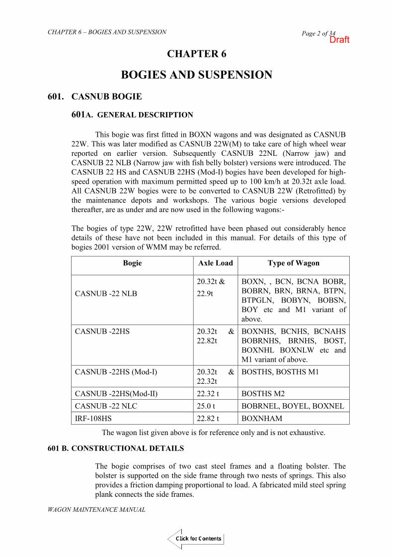
CHAPTER 6 – BOGIES AND SUSPENSION
WAGON MAINTENANCE MANUAL
Page 2 of 34
CHAPTER 6
BOGIES AND SUSPENSION 601. CASNUB BOGIE
601A. GENERAL DESCRIPTION
This bogie was first fitted in BOXN wagons and was designated as CASNUB 22W. This was later modified as CASNUB 22W(M) to take care of high wheel wear reported on earlier version. Subsequently CASNUB 22NL (Narrow jaw) and CASNUB 22 NLB (Narrow jaw with fish belly bolster) versions were introduced. The CASNUB 22 HS and CASNUB 22HS (Mod-I) bogies have been developed for high-speed operation with maximum permitted speed up to 100 km/h at 20.32t axle load. All CASNUB 22W bogies were to be converted to CASNUB 22W (Retrofitted) by the maintenance depots and workshops. The various bogie versions developed thereafter, are as under and are now used in the following wagons:- The bogies of type 22W, 22W retrofitted have been phased out considerably hence details of these have not been included in this manual. For details of this type of bogies 2001 version of WMM may be referred.
Bogie Axle Load Type of Wagon
CASNUB -22 NLB
20.32t & 22.9t
BOXN, , BCN, BCNA BOBR, BOBRN, BRN, BRNA, BTPN, BTPGLN, BOBYN, BOBSN, BOY etc and M1 variant of above.
CASNUB -22HS 20.32t & 22.82t
BOXNHS, BCNHS, BCNAHS BOBRNHS, BRNHS, BOST, BOXNHL BOXNLW etc and M1 variant of above.
CASNUB -22HS (Mod-I) 20.32t & 22.32t
BOSTHS, BOSTHS M1
CASNUB -22HS(Mod-II) 22.32 t BOSTHS M2 CASNUB -22 NLC 25.0 t BOBRNEL, BOYEL, BOXNEL IRF-108HS 22.82 t BOXNHAM
The wagon list given above is for reference only and is not exhaustive. 601 B. CONSTRUCTIONAL DETAILS
The bogie comprises of two cast steel frames and a floating bolster. The bolster is supported on the side frame through two nests of springs. This also provides a friction damping proportional to load. A fabricated mild steel spring plank connects the side frames.
Draft

CHAPTER 6 – BOGIES AND SUSPENSION
WAGON MAINTENANCE MANUAL
Page 3 of 34
BOGIE GENERAL ARRANGEMENT
CASNUB 22 NLB BOGIE
2000 (WHEEL BASE)
22
60
(JO
UR
NA
L C
EN
TR
ES
)
FIG. 6.1 BOGIE GENERAL ARRANGEMENT CASNUB 22 NLB
Draft
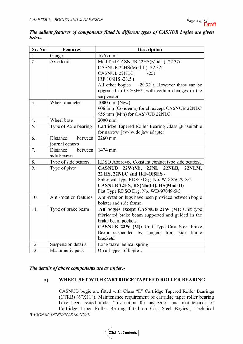
CHAPTER 6 – BOGIES AND SUSPENSION
WAGON MAINTENANCE MANUAL
Page 4 of 34
The salient features of components fitted in different types of CASNUB bogies are given below.
The details of above components are as under:-
a) WHEEL SET WITH CARTRIDGE TAPERED ROLLER BEARING
CASNUB bogie are fitted with Class “E” Cartridge Tapered Roller Bearings (CTRB) (6”X11”). Maintenance requirement of cartridge taper roller bearing have been issued under “Instruction for inspection and maintenance of Cartridge Taper Roller Bearing fitted on Cast Steel Bogies”, Technical
Sr. No Features Description 1. Gauge 1676 mm 2. Axle load Modified CASNUB 22HS(Mod-I) -22.32t
CASNUB 22HS(Mod-II) -22.32t CASNUB 22NLC -25t IRF 108HS -23.5 t All other bogies -20.32 t, However these can be upgraded to CC+8t+2t with certain changes in the suspension.
3. Wheel diameter 1000 mm (New) 906 mm (Condemn) for all except CASNUB 22NLC 955 mm (Min) for CASNUB 22NLC
4. Wheel base 2000 mm 5. Type of Axle bearing Cartridge Tapered Roller Bearing Class „E‟ suitable
for narrow jaw/ wide jaw adapter 6. Distance between
journal centres 2260 mm
7. Distance between side bearers
1474 mm
8. Type of side bearers RDSO Approved Constant contact type side bearers. 9. Type of pivot CASNUB 22W(M), 22NL 22NLB, 22NLM,
22 HS, 22NLC and IRF-108HS - Spherical Type RDSO Drg. No. WD-85079-S/2 CASNUB 22HS, HS(Mod-I), HS(Mod-II) Flat Type RDSO Drg. No. WD-97049-S/3
10. Anti-rotation features Anti-rotation lugs have been provided between bogie bolster and side frame
11. Type of brake beam All bogies except CASNUB 22W (M): Unit type fabricated brake beam supported and guided in the brake beam pockets. CASNUB 22W (M): Unit Type Cast Steel brake Beam suspended by hangers from side frame brackets.
12. Suspension details Long travel helical spring 13. Elastomeric pads On all types of bogies.
Draft

CHAPTER 6 – BOGIES AND SUSPENSION
WAGON MAINTENANCE MANUAL
Page 5 of 34
Pamphlet No. G-81of RDSO. However, for detailed maintenance and inspection of CTRB in open line, Handbook on Maintenance of CTRB for freight stock issued under CAMTECH Doc.No. IRCAMTECH/M/12-13/Bearing/1.0, December-20 12 may be referred. Wheel tread/tyre profile used earlier was standard 1 in 20 taper after the root radius. Currently a worn wheel profile or worn adapted profile has been prescribed to reduce wheel wear and increase wheel life. The tyre/ tread profile for new wheel is as per Drg No. WD-88021. As per requirement, during POH/ROH/Maintenance of wheel set/wheel re-profiling, wheels tread should be turned as per intermediate profile having varying wheel flange thickness selecting the appropriate flange thickness out of the nine flange thicknesses so that minimum material is removed at the time of turning. These intermediate profiles have been incorporated to optimise the wheel life. These are as per Drg. No. WD-89060- S/2. Wheel diameter for new wheel is 1000 mm. Condemning wheel dia is 906 mm for all versions except CASNUB 22NLC Bogie. Minimum wheel dia for CASNUB 22NLC bogie is 955 mm.
b) AXLE
Axles have to be subjected to ultrasonic testing during ROH/POH or
whenever the wagons are sent to the shops. Wheel sets whose axles have under gone ultrasonic testing shall be stamped on the hub fillet as per RDSO‟s drawing no. WD-81089-S/1.
Axle end holes should be properly cleaned and lubricated before reuse.
Threads should be checked with standard thread gauge. Reclamation of axles with defective cap screw holes shall be carried out as per instructions given in RDSO letter MW/WA/Genl dated 8.5.92.
Some axles on CASNUB bogies have been reported to have grazing on
account of Main pull rod. This can be reclaimed in case notches/scratch/nicks are less than 5 mm as per instructions issued vide RDSO‟s letter No. MW/WA/GENL dated 20.12.91. The reclamation of the axle, for reasons not indicated in the above quoted letter, is not permitted.
Whenever axles are renewed, the workshop shall punch the following
particulars in 5 mm letters on the axle end:-
i. Serial No. ii. Workshop code where pressing has been done iii. Date of pressing iv. Pressing on pressure in tonnes (Both ends)
After rediscing, the stamping shall be as per RDSO Drg No. WD-
87080/S-1.
Draft
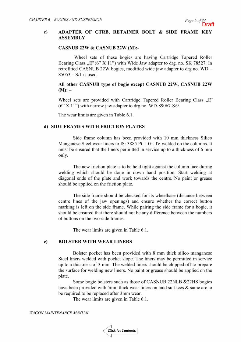
CHAPTER 6 – BOGIES AND SUSPENSION
WAGON MAINTENANCE MANUAL
Page 6 of 34
c) ADAPTER OF CTRB, RETAINER BOLT & SIDE FRAME KEY ASSEMBLY
CASNUB 22W & CASNUB 22W (M):- Wheel sets of these bogies are having Cartridge Tapered Roller Bearing Class „E‟ (6” X 11”) with Wide Jaw adapter to drg. no. SK 78527. In retrofitted CASNUB 22W bogies, modified wide jaw adapter to drg no. WD – 85053 – S/1 is used.
All other CASNUB type of bogie except CASNUB 22W, CASNUB 22W (M): – Wheel sets are provided with Cartridge Tapered Roller Bearing Class „E‟ (6” X 11”) with narrow jaw adapter to drg no. WD-89067-S/9.
The wear limits are given in Table 6.1.
d) SIDE FRAMES WITH FRICTION PLATES
Side frame column has been provided with 10 mm thickness Silico Manganese Steel wear liners to IS: 3885 Pt.-I Gr. IV welded on the columns. It must be ensured that the liners permitted in service up to a thickness of 6 mm only. The new friction plate is to be held tight against the column face during welding which should be done in down hand position. Start welding at diagonal ends of the plate and work towards the centre. No paint or grease should be applied on the friction plate. The side frame should be checked for its wheelbase (distance between centre lines of the jaw openings) and ensure whether the correct button marking is left on the side frame. While pairing the side frame for a bogie, it should be ensured that there should not be any difference between the numbers of buttons on the two-side frames. The wear limits are given in Table 6.1.
e) BOLSTER WITH WEAR LINERS Bolster pocket has been provided with 8 mm thick silico manganese
Steel liners welded with pocket slope. The liners may be permitted in service up to a thickness of 3 mm. The welded liners should be chipped off to prepare the surface for welding new liners. No paint or grease should be applied on the plate. Some bogie bolsters such as those of CASNUB 22NLB &22HS bogies have been provided with 5mm thick wear liners on land surfaces & same are to be required to be replaced after 3mm wear. The wear limits are given in Table 6.1.
Draft
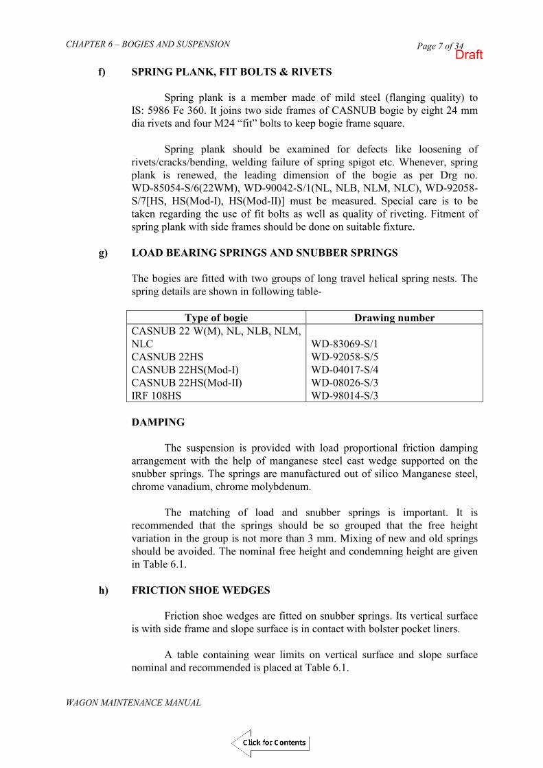
CHAPTER 6 – BOGIES AND SUSPENSION
WAGON MAINTENANCE MANUAL
Page 7 of 34
f) SPRING PLANK, FIT BOLTS & RIVETS
Spring plank is a member made of mild steel (flanging quality) to IS: 5986 Fe 360. It joins two side frames of CASNUB bogie by eight 24 mm dia rivets and four M24 “fit” bolts to keep bogie frame square.
Spring plank should be examined for defects like loosening of
rivets/cracks/bending, welding failure of spring spigot etc. Whenever, spring plank is renewed, the leading dimension of the bogie as per Drg no. WD-85054-S/6(22WM), WD-90042-S/1(NL, NLB, NLM, NLC), WD-92058-S/7[HS, HS(Mod-I), HS(Mod-II)] must be measured. Special care is to be taken regarding the use of fit bolts as well as quality of riveting. Fitment of spring plank with side frames should be done on suitable fixture.
g) LOAD BEARING SPRINGS AND SNUBBER SPRINGS
The bogies are fitted with two groups of long travel helical spring nests. The spring details are shown in following table-
Type of bogie Drawing number
CASNUB 22 W(M), NL, NLB, NLM, NLC CASNUB 22HS CASNUB 22HS(Mod-I) CASNUB 22HS(Mod-II) IRF 108HS
WD-83069-S/1 WD-92058-S/5 WD-04017-S/4 WD-08026-S/3 WD-98014-S/3
DAMPING The suspension is provided with load proportional friction damping arrangement with the help of manganese steel cast wedge supported on the snubber springs. The springs are manufactured out of silico Manganese steel, chrome vanadium, chrome molybdenum. The matching of load and snubber springs is important. It is recommended that the springs should be so grouped that the free height variation in the group is not more than 3 mm. Mixing of new and old springs should be avoided. The nominal free height and condemning height are given in Table 6.1.
h) FRICTION SHOE WEDGES
Friction shoe wedges are fitted on snubber springs. Its vertical surface is with side frame and slope surface is in contact with bolster pocket liners. A table containing wear limits on vertical surface and slope surface nominal and recommended is placed at Table 6.1.
Draft

CHAPTER 6 – BOGIES AND SUSPENSION
WAGON MAINTENANCE MANUAL
Page 8 of 34
i) CENTRE PIVOT ARRANGEMENT
Centre pivot arrangement for various bogies is as follows - Centre Pivot Arrangement Drawing No
CASNUB 22W(M),NL,NLB,NLM,NLC, CASNUB 22 HS bogies
WD-85079-S/2
CASNUB 22HS,HS(Mod-I),HS(Mod-II) WD-97049-S/3 IRF 108HS WD-98014-S/4
Note: In CASNUB 22 HS bogies, either a spherical or flat centre pivot can be fitted as applicable.
To determine the seat wear, the gauge should be placed in position. If the pivot surface starts touching the surface marked as „*‟ on the gauge at any point, repair to be made by welding. The gauge should be moved on the complete worn surface to be measured. The surface after reclamation shall be the original dimension as per the respective drawings for proper matching of surfaces with top centre pivot. The repairs should be carried out if a 7 mm thick shim in CASNUB bogie can be inserted for the full depth between the worn surface and the gauge at any point on the vertical wall of the bowl with gauge in position. During POH/ROH the wear on the vertical side of the bowl, seat of the bowl should be built up by welding. Preheat the surface to be reclaimed up to a maximum temperature of 250° Celsius. After welding, it should be allowed to cool slowly by covering the welded portion with asbestos/sand.
j) SIDE BEARER
CASNUB bogies are fitted with RDSO approved constant contact and PU pad type side bearers riveted/bolted on bolster.
k) ELASTOMERIC PAD
Elastomeric pads are provided in all versions of CASNUB bogies. The main purpose of providing elastomeric pad is to reduce wheel flange wear. Elastomeric pads and metal bonded rubber type constant contact side bearer pads shall be condemned and replaced by new ones on the following grounds :-
i. If the top of the bottom plates or intermediate plate in case of side
bearer pads show any crack in service.
ii. If any crack of more than 50 mm is developed at any surface of rubber.
Draft

CHAPTER 6 – BOGIES AND SUSPENSION
WAGON MAINTENANCE MANUAL
Page 9 of 34
iii. If a bond failure giving way more than 40 mm in any direction is developed in service.
iv. If any sign of crushing of rubber is noticed.
v. When in free condition, the pad has taken a permanent set of the order given in Table 6.1/ respective drawing.
l) BOGIE BRAKE GEAR
The brake gear mainly consists of Brake Beam (with brake head and brake block assembly), equalising levers, Push rod, End pull rod, Brake Beam hangers (in CASNUB 22W(M) bogies). The pins and bushes provided are as per IS :5517-45C8 hardened/tempered and hardness of pins and bushes to be 250-280 BHN. Material for washer to be IS :2062 Fe410WA. The maximum permissible wear on the pin diameter and bush inside diameter is limited to 1.5 mm. In service as the tread diameter of wheel decreases due to wear, pins located in End Pull Rod with under frame to be relocated. In case of CASNUB 22W(M) bogies it is of cast steel and Brake head and Block assembly is a separate assembly. This assembly attached with the circular end of a cast steel Brake beam by means of a pin. In all other bogies the brake beam is fabricated. Brake beam strut and end piece casting are of cast steel. Brake head is integral part of “End Piece Casting”.
m) BRAKE BEAM [IN ALL BOGIES EXCEPT CASNUB 22W(M)] AND BRAKE WEAR PLATES
Bogies are fitted with unit type fabricated brake beams that slide in the
guide cavity provided in the side frame. Cavities are provided with silico manganese steel liners. The brake
heads are integral part of the brake beam. Brake beam is shown in WD-89033-S/1, however the brake block to WA/BG-6158 is common for all versions.
CASNUB 22W(M) Bogies
The bogie is fitted with unit type suspended cast steel brake beam. The brake head is a separate sub assembly which is fixed with brake beam circular end by means of pin passing through brake beam end and brake shoe adjuster along with spring loaded brake head. Assembly provides rotational flexibility to brake head. Details are shown in Drg No. WD-85084-S/1, WD-88012-S/1 & WD-86034-S/1.
Draft
CHAPTER 6 – BOGIES AND SUSPENSION
WAGON MAINTENANCE MANUAL
Page 10 of 34
n) RECLAMATION OF BRAKE BEAM ON ACCOUNT OF WORN OUT BRAKE HEADS
Reclamation procedure for different versions of CASNUB bogie brake
beams shall be as follows.
I) CASNUB 22 W(M) Bogie Brake heads are fitted on brake beam with the help of brake shoe adjuster as shown in drawing no. WD-88012-S/1. Brake heads are further secured on brake beam-ends by washer and split pin. Procedure for replacing worn out brake heads is as under; i. Remove split pin and washer from brake beam end. Remove pin
securing brake shoe adjuster with brake beam by removing split pin.
ii. Take brake heads out of brake beam along with brake shoe adjuster.
iii. Disengage brake shoe adjuster from brake head by providing bolt after disengaging split pin, nut cover, spring and adjusting piece.
iv. Assemble new brake head with brake shoe adjuster by using items mentioned in para (III) as shown in RDSO Drawing No. WD-88012-S/1.
v. Slide new brake head assembled with brake shoe adjuster on brake beam end. Engage brake shoe adjuster with brake beam by using pin and split pin as shown in RDSO Drawing No. WD-88012-S/1.
vi. Further secure brake heads on brake beam end by putting washer and split pin as shown in RDSO Drawing No WD-85054-S/4.
II) CASNUB 22 NL, 22NLB, 22NLM, 22NLC, 22HS, 22HS (Mod-I)
22HS (Mod-II) & IRF-108HS Bogies
Brake head is integrally cast with end piece casting, which is welded with structural steel brake beam channel and Truss flat at ends as shown in RDSO Drawing No WD-89033-S/1. Depending upon the extent of wear, worn out brake heads can either be built up by welding or worn out brake heads can be replaced by new brake head. Replacement of brake head of brake beam should be done on appropriate fixture.
601 C. REPAIRS AND MAINTENANCE IN SICK LINE
In order to obtain optimum life from the bogie, it is desirable to maintain the various clearances within recommended limits. Prescribed clearances are given in para 601 E.
Draft

CHAPTER 6 – BOGIES AND SUSPENSION
WAGON MAINTENANCE MANUAL
Page 11 of 34
a. Due to wear of the mating components, increase in clearances should be monitored. Whenever the component reaches the condemning limits, repairs should be undertaken for either building up the wear on such surfaces or changing their liner, as the case may be.
b. Due to the wear in bolster/side frame liners and wedge surface, the wedges
shall move upwards. If the holes of bolster pocket wall and wedges starts crossing, repair shall be under taken. The gauge shall be used for determining the wear.
c. The class of electrode, gauge of electrode, welding current and welding
precautions to be taken while repairing the surfaces by welding.
601 D. REPAIR AND MAINTENANCE DURING ROH & POH
In addition to all the work prescribed at para 601 C above, the following work is also to be done in ROH/POH :- a. The bogie should be dismantled during ROH. Dismantling and assembly
procedure is given in para e. The bogie clearances and tolerances should be checked and rectified, if found necessary.
b. Position the job for down hand welding and carry out the repairs. Ensure that suitable manipulators are used.
c. After the repairs the repaired surface should be checked with relevant gauge for correctness. Excess material, if any, should be removed by grinding or machining.
d. During POH of wagon in shops, bogies are to be dismantled and all the wearing surfaces of bogie shall be brought to “As New” condition.
e. Assembly and disassembly of the bogie
I. DISASSEMBLY
Remove shackle of centre pivot pin.
Disconnect bogie end pull rod from under frame and brake pull rod from equalizing lever to raise wagon body. Run out the bogie.
Inset assembly pin (12mm dia x 250 mm long) to retain friction shoes. Raise bolster to touch top of side frame. Remove outer, inner and snubber springs. Remove assembly pins and lower wedge blocks to take them out.
Draft

CHAPTER 6 – BOGIES AND SUSPENSION
WAGON MAINTENANCE MANUAL
Page 12 of 34
Lower bolster to rest on the spring plank. Slide the bolster to one side to take it out. Take out the S/Frame key from side frame to release the wheel sets,
adapter and elastomeric pad.
Remove the adapter retainer bolt in CASNUB 22W (M) to release the wheel sets adapter and elastomeric pad.
Take out spring plank from side frame assembly if necessary.
II. ASSEMBLY
After repair/reclamation and gauging of components with
respective gauge, assembly of the bogie shall be done by reversing the procedure of disassembly.
During assembly of the bogie following points should be taken care -
(a) Matching of both load and snubber spring is important. It is recommended that springs having up to 3 mm free height variation should be assembled in same group. Mixing of new and old springs should be avoided.
(b) Free height of spring / group and wheel dia for bogie assembly
should be so selected such that combined drop of centre pivot should not be more than 25mm from that of new bogie. This will help in achieving proper buffer height in loaded condition. Use of 12mm and 35mm packing are also required to be provided as per existing instructions.
(c) The centre pivot of the bogie shall be lubricated with about 200g –
300g graphite flakes to IS:495 at the time of assembly. No other mating surface in the bogie shall be lubricated.
Important: Inspect all the load and snubber springs for proper seating after wagon body is on bogies.
For detailed description of each item and its maintenance procedure, refer to RDSO publication No. G-95 (Latest Revision).
Draft

CHAPTER 6 – BOGIES AND SUSPENSION
WAGON MAINTENANCE MANUAL
Page 13 of 34
601 E. NOMINAL CLEARANCES
The nominal clearances and the tolerances of the bogie assembly are given below.
Sr. No
Description Type of CASNUB Bogie
22W(M) 22NL,
NLB,NLM,NLC
22HS, HS (Mod-I&II) IRF-108HS
1. Lateral clearance between side frame & bolster
18 mm 18 mm 25 mm
2. Lateral clearance between side frame & adapter
25 mm 16 mm 16 mm
3. Longitudinal clearance between side frame & adapter
10 mm 9 mm 9 mm
4. Longitudinal clearance between side frame & bolster
6mm 6mm 6mm
5. Clearance between anti- rotation lug & Bolster
4mm 4mm 4mm
TABLE 6.1 WEAR LIMITS FOR BOGIE COMPONENTS
Sr. No.
Description New or Renewed
Worn Wear Limit
1. AXLE BOX Axle Box Crown lugs (Cylindrical Roller Bearings) 159 mm 167 mm 4 mm Axle Box Crown seat (Cylindrical Roller Bearings) 36.5 mm 33 mm 3.5 mm Axle Box side lugs (Cylindrical Roller Bearings) 130 mm 136 mm 3 mm Axle Box sides (Cylindrical Roller Bearings) 268 mm 262 mm 3 mm
2. ADAPTER Adapter Crown lugs (Wide Jaw) 156 mm 164 mm 4 mm
(One Side) Adapter Crown lugs (Narrow Jaw) 155.5 mm 163.5 mm 4 mm
(One Side) Adapter Crown seat 3.5 mm Adapter bore seat to crown seat Wide jaw adapter 48.5 mm 45 mm 3.5 mm Modified wide jaw adapter 25.5 mm 22 mm 3.5 mm Narrow jaw adapter 26.2 mm 22.7 mm 3.5 mm Adapter Side Lugs Wide Jaw Narrow Jaw
130 97
136 103
3 3
Draft

CHAPTER 6 – BOGIES AND SUSPENSION
WAGON MAINTENANCE MANUAL
Page 14 of 34
Adapter Sides Wide Jaw Narrow Jaw
268 181
262 175
3 3
3. Side Frames Side frame wear friction plate Side frame column sides Side frame anti rotation lug
10 216 522
6 206 528
4 10 6
4. Pedestal Crown Roof Key Seat to Pedestal Crown Roof 22W(M) Key Seat to Pedestal Crown Roof 22NL/ NLB/HS/IRF 108HS
318
323
323
328
5 5
5. Pedestal Crown Sides and Sides of the Pedestal All Bogies – Crown Sides Pedestal Sides 22W(M) Pedestal Sides 22NL,NLB, HS, IRF 108HS
152 105 81
144 101 77
4 2 2
6. Distance between Outer & Inner Pedestal Jaw of CASNUB Bogies 22W(M) Pedestal Jaw (Short) for 22NL/NLB/HS, IRF 108HS Pedestal Jaw (Long) for 22NL/NLB/HS, IRF 108HS
278 190
236
286 198
244
4 4 4
*Adapter of CTRB shall not be welded/reclaimed/renewed at any location
Description New Worn Wear Limit BOLSTER Pocket 35°/270 +1° on slope Liner 8 mm 3 mm 5 mm Bolster land surface 444 mm 438 mm 3 mm Rotation stop lug 518 mm 512 mm 3 mm
BOLSTER COLUMN GIBS Outer gib 234/241 mm 244/251 mm 5 mm Inner gib 136 mm 146 mm
CENTRE PIVOT Wear limit vertical side - 4 mm
SEAT - - 4 mm
FRICTION SHOE WEDGE BLOCK
Vertical Surface from Centre line of spigot 61 mm 54 mm 7 mm Slope surface by gauge - - 3 mm
Draft

CHAPTER 6 – BOGIES AND SUSPENSION
WAGON MAINTENANCE MANUAL
Page 15 of 34
ELASTOMERIC PADS & CONSTANT CONTACT SIDE BEARER
Type of pad Free height Condemning free height Elastomeric pad 46+1 mm 42 mm Constant contact side bearer pad A. Metal bonded Rubber pad 114+3-0 mm 109 mm B. PU side bearer (Three Rings) 142.5+1.6 mm 137 mm C. PU side bearer (Two Rings) 134+1.5 mm 128.5 mm LOAD SPRINGS
Bogie Type SPRINGS Spring free height nominal (mm)
Recommended free height condemning (mm)
CASNUB 22 W(M), NL, NLB, NLM & NLC
Outer 260 245 Inner 262 247 Snubber 294 279
CASNUB 22HS Outer 260 245 Inner 243 228 Snubber 293 278
CASNUB 22HS(Mod-I) Outer 253 238 Inner 225 210 Snubber 304 289
CASNUB 22HS(Mod-II) Outer 253 238 Inner 222 207 Snubber 304 289
IRF-108HS
Outer 264 249 Inner 246 231 Snubber 296 281
It is recommended that springs having less than 3 mm free height variation should be assembled in the same group. Mixing of new and old spring must be avoided. The bogie is fitted with two groups of long helical spring nests. The spring groups per bogie for various axle load applications are as under: Type of Bogie Axle Load Number of Springs
Outer Inner Snubber CASNUB 22 W(M), NL,NLB, NLM
20.32t 12 8 4
CASNUB 22 W(M), NL,NLB, NLM
CC+8t+2t 14 10 4
CASNUB 22HS 20.32t 14 12 4 CASNUB 22HS CC+6t+2t and
CC+8t+2t 14 14 4
CASNUB 22HS(Mod-I) 20.32t 12 12 4 CASNUB 22HS(Mod-II) 22.32t 12 12 4 CASNUB 22NLC 25t 14 14 4 IRF-108HS 22.82t/23.5t 14 14 4
Draft

CHAPTER 6 – BOGIES AND SUSPENSION
WAGON MAINTENANCE MANUAL
Page 16 of 34
601 F. REFERENCE DRAWING NUMBERS FOR COMPONENTS
Sr. No. Components Drawing No./Pamphlet No. 1. Cartridge Tapered Roller Bearing (CTRB) RDSO Drg. No. WD-92089-S-01/G -81 2. Worn Wheel Profile on wheel tread WD-88021 3. Wheel tread Intermediate Profile WD-89060/S-2 4. Wide jaw adapter for CASNUB 22 W,
CASNUB 22 W(M) & BLC wagon Bogie
RDSO Drg. No. SK-78527
5. Modified Wide jaw adapter for Retrofitted CASNUB 22 W
Modified wide jaw adapter to RDSO Drg. No. WD-85053-S/1
6. Narrow jaw adapter for all other CASNUB bogie except CASNUB 22W & CASNUB 22 W(M)
RDSO Drg. No. WD-89067-S/9
7. CASNUB 22 W(M) wheel set WA/WL-4902/WD-89025-S/1 8. All other CASNUB bogie wheel sets WD-89025-S/1 9. BLC bogie wheel sets RDSO Drg. No. CONTR-9404-S/12 10. Leading dimension and tolerances WD-85054-S/6(22WM), WD-90042-
S/1(NL,NLB,NLM,NLC), WD-92058-S/7(HS), WD-04017-S/7 (HS Mod-I &Mod-II)
11. Load bearing Springs & Snubber Springs
WD-83069-S/1(All versions except 22HS Bogies) WD-92058-S/5 (22HS ), WD-04017-S/4(HS Mod-I), WD-08026-S/3(HS Mod-II) WD-98014-S/4 (IRF-108HS)
12. Springs Silico Manganese steel to IS : 3195 Gr 60 Si7 & Gr 52Cr4Mo2V and RDSO specification WD-01-HLS-94 (rev.3)
13. Centre pivot other than CASNUB 22W WD-85079-S/2 & WD-97049-S/3 14. Elastomeric Pads WD-95005-S/1 for all 15. Side Bearers R.D.S.O. Approved CCSB. 16. Brake Block WA/BG-6158 17. CASNUB 22W(M) bogie, brake beam,
brake head & block assembly WD-85084-S/1, WD-88012-S/1, WD-86034-S/1
18. Brake beam [Other than CASNUB 22W(M)]
WD-89033-S/1
602. FABRICATED BOX BOGIE (UIC BOGIE)
Para has been deleted. If required, Wagon Maintenance Manual ver. 2001 may be referred.
603. Para has been deleted. If required, Wagon Maintenance Manual ver. 2001 may be referred.
604 & 605 Para has been deleted. If required, Wagon Maintenance Manual ver. 2001 may be referred.
Draft

CHAPTER 6 – BOGIES AND SUSPENSION
WAGON MAINTENANCE MANUAL
Page 17 of 34
606. WHEEL ASSEMBLY
A. Axle
An axle is a steel shaft on which the wagon/rolling stock wheels are mounted. The axle holds the wheels to gauge and transmits the load from the journal bearing to the wheels. Carriage & Wagon axle is made of steel to specification No. IRS-R-16. Its journal portion is suitably designed to mount a bearing. The axle can be divided into following portions:-
i. Portion between the wheel seats called axle body ii. Wheel seat on either side. iii. Shoulders just after the wheel seat on either side. iv. Journal just after the shoulder on either side.
The portion of the axle on which the wheel is pressed is known as wheel seat. The seat is fine finish machined as per drawing requirements. The shoulder portion is also fine finish machined as per drawing. Two small axle centres are drilled on end surfaces on the axle. These holes facilitate turning of the axle on centre lathes, grinding/furnishing of the journals and turning of the tyre on the wheel lathe.
Axle on which bearings are mounted should have surface finish and ovality as per drawing. To facilitate the locking of bearing in position, three holes are built and tapped on each face of the axle.
LIST OF DRGS. FOR AXLE OF DIFFERENT WAGONS
S.
No. Drawing No. Of Finished Axle
Axle Load(T)
Type Of Wagons
Nominal Wheel Seat Dia. In
New Finished Condition**
Condemning Wheel Seat Dia. **
1. WD-89025-S-02 22.9 BOXN, BCN, BRN, BOBR, BTPN (Fitted with CASNUB 22 NLC BOGIES)
213 mm
207 mm
2. WD-89025-S-02 25* BOXN EL, BOY EL (Fitted With CASNUB 22 NLC Bogies)
213 mm
211 mm
3. WD-89025-S-02 22 BLC WAGONS 213 mm 207 mm 4. SK-69601 22.9 BOY, BOBS-
MARK-II, BOXN (with CYL. BRG.) & BFKX
210 mm 207 mm
5. WD-92064-S-01 22.9 BWT/A, BWL 210 mm 202 mm
Draft
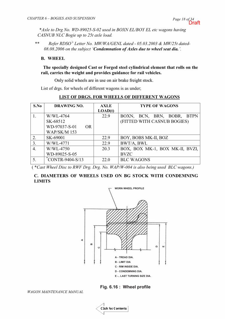
CHAPTER 6 – BOGIES AND SUSPENSION
WAGON MAINTENANCE MANUAL
Page 18 of 34
*Axle to Drg No. WD-89025-S-02 used in BOXN EL/BOY EL etc wagons having CASNUB NLC Bogie up to 25t axle load.
** Refer RDSO’s Letter No. MW/WA/GENL dated - 05.03.2003 & MW/25t dated- 08.08.2006 on the subject ‘Condemnation of Axles due to wheel seat dia.’.
B. WHEEL The specially designed Cast or Forged steel cylindrical element that rolls on the
rail, carries the weight and provides guidance for rail vehicles.
OOnnllyy ssoolliidd wwhheeeellss aarree iinn uussee oonn aaiirr bbrraakkee ffrreeiigghhtt ssttoocckk..
List of drgs. for wheels of different wagons is as under;
LIST OF DRGS. FOR WHEELS OF DIFFERENT WAGONS
S.No DRAWING NO. AXLE LOAD(t)
TYPE OF WAGONS
1. W/WL-4764 SK-68512 WD-97037-S-01 OR WAP/SK/M 153
22.9 BOXN, BCN, BRN, BOBR, BTPN (FITTED WITH CASNUB BOGIES)
2. SK-69001 22.9 BOY, BOBS MK-II, BOZ 3. W/WL-4771 22.9 BWT/A, BWL 4. W/WL-4750
WD-89025-S-05 20.3 BOX, BOX MK-1, BOX MK-II, BVZI,
BVZC 5. *CONTR-9404-S/13 22.0 BLC WAGONS
( *Cast Wheel Disc to RWF Drg. Drg. No. WAP/W-004 is also being used BLC wagons.)
C. DIAMETERS OF WHEELS USED ON BG STOCK WITH CONDEMNING LIMITS
Fig. 6.16 : Wheel profile
A - TREAD DIA.
B - LIMIT DIA
C - RIM INSIDE DIA.
D - CONDEMNING DIA.
E -.. LAST TURNING SIZE DIA.
WORN WHEEL PROFILE
A
B
C D E
Draft

CHAPTER 6 – BOGIES AND SUSPENSION
WAGON MAINTENANCE MANUAL
Page 19 of 34
The last shop issue size and the condemning dia of different wheels shall be as per RDSO Drg.No.WD-88089/S-1 given below;
S. No. Axle (t)
Drg. No. Nom. Dimensions A B C D E
1. 22.9 W/WL-4764*/SK-68512 1000 897 850 906 919
2. 22.9 WAP/SK/M/153 or
WD-97037-S-01
1000 897 - 906 919
3. 22.9 SK69601 1000 897 850 906 919
4. 22.9 W/WL-4771 915 804 761 813 826
5. 20.3 W/WL-4750 1000 851 814 860 873
6. 20.3 WD-89025/S-5 1000 851 814 860 873
7. 22.0 CONTR-9404-S-13 840 771 730 780 793
* Minimum service diameter of wheel disc in 25 T axle load having CASNUB 22 NLC bogie like BOXNEL, BOYEL etc. is 955 mm. Last shop issue size of such wheels is 963 mm.
Draft
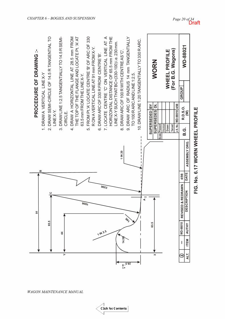
CHAPTER 6 – BOGIES AND SUSPENSION
WAGON MAINTENANCE MANUAL
Page 20 of 34
1.D
RAW
A V
ER
TIC
AL
LIN
E X
-Y2.
DR
AW S
EM
I-CIR
CLE
OF
14.5
R T
AN
GE
NTI
AL
TO
LIN
E X
-Y.
3.D
RAW
LIN
E 1
:2.5
TA
NG
EN
TIA
LLY
TO
14.
5 R
SE
MI-
CIR
CLE
.4.
DR
AW A
HO
RIZ
ON
TAL
LIN
E A
T 28
.5 m
m F
RO
M
THE
TO
P O
F TH
E F
LAN
GE
AN
D L
OC
ATE
Pt.
'A' A
T 63
.5 m
m F
RO
M T
HE
LIN
E X
-Y.
5.FR
OM
Pt.'
A' L
OC
ATE
CE
NTR
E 'B
' OF
AR
C O
F 33
0 R
ON
A V
ERTI
CA
L LI
NE
AT
91
FR
OM
X-Y
.6.
DR
AW A
RC
OF
330
R F
RO
M C
EN
TRE
'B'.
7.LO
CAT
E C
EN
TRE
'C' O
N V
ER
TIC
AL
LIN
E A
T A
H
OR
IZO
NTA
L D
ISTA
NC
E O
F 65
.5
FR
OM
TH
E
LIN
E X
-Y S
UC
H T
HAT
BC
=(33
0-10
0) i.
e. 2
30
8.D
RAW
AR
C O
F 10
0 R
WIT
H C
EN
TRE
AS
'C'.
9.D
RAW
AR
C O
F R
AD
IUS
14
TAN
GE
NTI
ALL
Y
TO 1
00 R
AR
C A
ND
LIN
E 1
:2.5
.10
. DR
AW L
INE
1:2
0 TA
NG
EN
TIA
LLY
TO
330
R A
RC
.
mm
mm
mm
.
mm
FIG
. No.
6.1
7 W
OR
N W
HEE
L PR
OFI
LE
WO
RN
WH
EEL
PRO
FILE
(For
B.G
. Wag
ons)
WD
-880
21G
RO
UP
SUPE
RSE
DED
BY
SUPE
RSE
DES
Dt.
Sc
ale
Pa
sse
d
Ch
eck
ed
Dra
wn
Tarc
ed
J.S
. No
.W
D-9
801
84/
98
R.D
.S.O
.(W
)B
.G.
ASS
EMB
LY D
RG
.
4/98
DAT
ER
EVI
SED
& R
ED
RAW
ND
ESC
RIP
TIO
NA
LT.
AU
THY
WD
-980
18
ITEM
X
A
63.5
14.5
R
14R
28.5+1- 0
Y
C
44
B
65.5
91
100R
1 IN 2.5
330R
1 IN
20
PRO
CED
UR
E O
F D
RAW
ING
:-
Draft

CHAPTER 6 – BOGIES AND SUSPENSION
WAGON MAINTENANCE MANUAL
Page 21 of 34
Fig. 6.18 Intermediate Profile (WD-89060/S-2), Continue…………
Draft

CHAPTER 6 – BOGIES AND SUSPENSION
WAGON MAINTENANCE MANUAL
Page 22 of 34
Fig. 6.18 Intermediate Profile (WD-89060/S-2), Continue…………
Draft

CHAPTER 6 – BOGIES AND SUSPENSION
WAGON MAINTENANCE MANUAL
Page 23 of 34
Fig. 6.18 Intermediate Profile (WD-89060/S-2)
Draft

CHAPTER 6 – BOGIES AND SUSPENSION
WAGON MAINTENANCE MANUAL
Page 24 of 34
C. RE-AXLING & REDISCING Defective axles, which cannot be repaired, otherwise, are required to be replaced. The axles requiring replacement are pressed out of the wheels discs on a Wheel Press specially designed for this purpose. After machining new axles to the required size, wheel discs are pressed on it on the press. After the wheel discs are pressed out, the bore shall be machined to specified finish as per drawings on a vertical boring machine. The depth of cut should be minimum possible, just enough to remove the irregularity of the surface and to ensure fine finish machined surface. The finish size of the bore should be taken and wheel seat of the axle should be surface finish/roughness machined accordingly to a higher diameter giving allowance for the required interference fit. The selective assembly of Wheels and axle will be done so as to obtain an interference between wheel seat and bore of 1 mm per meter (0.001 mm per mm) dia. of wheel seat and to ensure assembly pressure build-up of 400 to 600 Kg. per mm. dia. of wheel seat . During assembling process/assembly of wheel and axle shall satisfy Para -2, 3, 5 & 7 of IRS specification R-19/93 Part I. While pressing the wheel, care should be exercised to see that the pressing is stopped at a pre-marked correct location on the inner side of the wheel seat.
At the time of re-axling, following points to be ensured:-
i. Before mounting the wheels on axles, carefully clean the wheel seat and
bore of the wheel to remove rust grit, chips and grease. ii. Coat wheel seat and bore with mixture of basic carbonate white lead and
boiled (not raw) linseed oil to avoid scoring of mounting surface. iii. Keep special care so that wheel-seat and bore and not damaged during
mounting operation. iv. Mounting press must have dial pressure gauge and a pressure recording
gauge. v. Mount the wheels centrally on axle at a proper gauge distance. vi. Recorder must be maintained and kept properly adjusted all the time. vii. Check wheel mounting and check gauge frequently so that excessive wear
does not allow improper mounting of wheels. viii.Stamp at the front Hub edge for the rediscing particulars as per RDSO
Drg. No. WD-87080/S-1 to facilitate tracing of history of the wheels. ix. After mounting of wheels on axle apply rail gauge at three or more equi-
distant points around the circumference to see that wheels are within gauge limits.
D. TYRE TURNING OR REPROFILING
To remove irregular surface on the profile caused due to wear in service re-profiling is to be done. In service some of the wheels develop defects beyond the permissible limit for the safe turning. Such wheels are to be withdrawn and should be sent to workshop for removing the defects. The wheel requiring re-profiling shall be
Draft
CHAPTER 6 – BOGIES AND SUSPENSION
WAGON MAINTENANCE MANUAL
Page 25 of 34
turned to worn wheel profile or to intermediate profile to RDSO Drg. No. WD-88021 or WD –89060/S-2 respectively. On receipt of wheels in wheel shop, the diameter of both the discs at wheel tread should be measured. Some times wheel with unequal dia. on the same axle are received. Many times skidded wheels are received due to which tyre surface at some spots gets hard. Such spots can not be machined on wheel lathes available in many workshops. Such wheels should be sent to re-profiling section for softening the hard spots on suitable designed furnaces. After softening, the wheels should be sent to tyre turning section.
Tyre turning is done on a specially designed wheel lathe. The root radius, vertical inclined surface, radius on the top of the flange are difficult portions to be machined. To machine these portions, specially designed gadgets are provided on the Tool ports.
While tyre-turning, the following should be kept in mind:-
i. The wheel gauge, i.e. the distance between the flanges of the 2 wheels of the same axle should be within the laid down limit. The aspect has to be particularly ensured when new tyres have been fitted. On old tyres normally the distance is correct. But in some cases where the machining has not been done accurately in the past, the distance may be beyond the permissible limit. If the distance is less it can be corrected by machining the side surface of the wheel. In case the distance is more, the wheel shall required re-axling. It is very important that the turner of the wheel lathe checks this distance at the time of turning in addition to the check done by incoming Inspection staff. The laid down distance is 1600 +2/-1 mm for BG.
ii. The variation in tread diameter of wheel tread/ tyres on the same axle after
fresh turning on surface wheel lathe/ under floor wheel lathe/pit wheel lathe should not exceed 0.5 mm. The turner normally machines the wheels to equal diameters. However, small variation may occur if the cut has not been taken carefully. After finishing the operators should assure dia of both wheels. If the difference is more than 0.5 mm he should take another cut on the tyre having the large diameter.
E. PAIRING OF WHEELS Different wheels fitted on a wagon are to be paired. Normally it is done in the
Lifting section of the wagon shop. Where large number of wheels of the same type are turned on each day, no difficulty is experienced for such pairing. However, when
the supply of wheels to Lifting section is from hand to mouth such pairing for the day‟s requirement has to be done in the tyre, turning section of the Wheel shop itself. Pairing in Wheel shop also becomes necessary for special tyre of wheels received in small numbers. When pairing is done in the Wheel shop, it becomes necessary to turn such wheels even to lesser diameters than is required from the point of view of wear. For such cases specific instructions should be given to turner of the Wheel lathe.
Draft

CHAPTER 6 – BOGIES AND SUSPENSION
WAGON MAINTENANCE MANUAL
Page 26 of 34
The variation in tread diameter should be as per Clause 2.8.14.2 of IRCA Part III. F. WHEEL DEFECTS
The wheels are required to be withdrawn from service for the following major defects:-
i) Reached condemning limits ii) Flat places/skidded iii) Flanges sharp/deep/thin iv) Too insufficient radius at the root of flange v) Gauge slack/tight vi) Cracked or broken
Defects i) to iv) mentioned above are detected with the help of tyre Defect Gauge. Defect as in item (v) is checked by Wheel Gauge. Defect as in item (vii) is determined by visual examination.
Permissible maximum flat surfaces on tread are as under:
Wagon Type Permissible Flat Surface BG Wagons 60 mm
a) THIN AND SHARP FLANGE
(i) For proper method of using Tyre Defect Gauge, please refer IRCA Part III .
(ii) Wheel may be passed provided the minimum thickness of flange is 16 mm.
(iii) Wheel must not be allowed to run if flanges are worn to knife edge but may be passed if the radius is not less than 5 mm.
(iv) Wheels with too small radius at the root of flange should not be allowed to remain in service.
607. GREASE FOR CTRBs
Grease to RDSO‟s Specification No. WD-24- MISC-2003 is to be used in CTRB. Before applying the grease, clean all the equipment to be used for lubrication. Apply grease to each single assembly and between the roller and cage assemblies in the quantity as given below:
Amount of grease to be applied
To Single Roller Assembly (Each Cone Assembly)
Between Roller Assembly (Around spacer)
Total + 30 gm
115 gm 170 gm 400 gm
Draft

CHAPTER 6 – BOGIES AND SUSPENSION
WAGON MAINTENANCE MANUAL
Page 27 of 34
608. MAINTENANCE AND REPAIR OF CARTRIDGE TAPERED ROLLER BEARINGS
The following are the recommended practices for long life and trouble-free operation of Cartridge Tapered Roller bearings:
(a) Recommended Practices for Railway Workshops:
i) Cleaning, inspection and assembly of cup & cones to be done in controlled environment to avoid ingress of dust particles.
ii) 100 % checking of groove depth of seal wear ring and re-use of only correct wear ring or replace with new one. Use of seal wear rings with vent holes needs to be stopped immediately. Use of proper measuring instrument is required for seal wear ring groove depth.
iii) Bearing mounting machine needs to be periodically calibrated for its proper
working at specified force (50 +/- 5 Tons) with ensuring holding for specified time (5 seconds). Use of the proper fixture (tooling) needs be ensured. The pressure – force conversion configuration for the specified machine may be prominently displayed near the mounting area for the benefit of the mounting staff.
Draft

CHAPTER 6 – BOGIES AND SUSPENSION
WAGON MAINTENANCE MANUAL
Page 28 of 34
iv) Checking of journal diameter at three locations with snap gauges may be enforced for ensuring specified fits to obtain the desired mounting force.
v) Checking of fillet radius after proper cleaning for correct seating/ fitment of
backing ring may be ensured. Backing rings with vent holes should not be reused. They should be replaced with plugged backing rings or new backing rings
vi) Proper tightening of end cap screws with periodically (monthly) calibrated
torque wrench at specified torque may be ensured on wheel sets. The specified torque should be maintained to 40 Kg – m (290 foot-pound). The torque wrench must be maintained with an accuracy of +/- 4% (Maximum). Minimum 2 passes and maximum 5 passes to be applied to ensure proper clamping. If any screw movement persists after 5 passes check for any irregularity.
Draft

CHAPTER 6 – BOGIES AND SUSPENSION
WAGON MAINTENANCE MANUAL
Page 29 of 34
vii) Axle threads to be checked with Go- No Go gauge and Axle thread holes should be cleaned by compressed air.
viii) Inside surface of Adapter is required to checked for wear on thrust shoulder
and bearing seating area/adapter machined relief with proper gauges (Sample gauge is depicted below). Gauging as per G 95 may be ensured.
ix) Assembly of bogie using properly checked adopter may be ensured. Railway workshops must manufacture/procure specified gauges for this checking. Cups should be checked for wear patterns seen on the cup outside diameter as it reveals excessive wear of the adapter. The figure below shows normal wear bands present on cup OD generated from a serviceable adapter.
Wear bands formed due to excessively worn out adapter are illustrated below. In case of fully worn out adapter, the cup starts contacting the adapter at the ends also. Worn out adapters must be scrapped. Displaced adapters also form two distinguished marks on the cup outside diameters. And such cups must be examined for spalls being generated on raceways under the adapter contact areas.
Draft

CHAPTER 6 – BOGIES AND SUSPENSION
WAGON MAINTENANCE MANUAL
Page 30 of 34
x) Checking of the mounted end lateral play may be ensured on each mounted CTRB. This is critical to bearing performance. With correct mounted lateral more roller share the load. As a result, peak load on individual rollers are less. Excessive mounted lateral causes high peak roller loads. As a result of fewer rollers sharing the load. This reduces fatigue life.
xi) Welding on the wagon after lowering of bogie shall be avoided as far as
possible. If any welding work is done after assembly of wagon proper earthling shall be ensured (specifically in odd hours) so that electric current does not pass through the bearings. The earthing should be done very close to welding area and the earthing wire should be tightly secured at both ends. Alternatively the earthing can be done with a earthing wire/strip running parallel to the track instead of earthing with the rails. If wagon is not properly earthed the current passing through the bearings will cause arcing in between the rollers and the raceways leading to failure. All the earthling ports may be properly grounded through periodically calibrated earth pits. One of the recommended scheme of earthing is shown below:
xii) Separate investigation of defective CTRBs coming from divisions may be
done. xiii) The fitment of cup and cones of same make in overhauled CTRBs may be
ensured. To the extent possible they may be maintained with similar age profile.
Draft
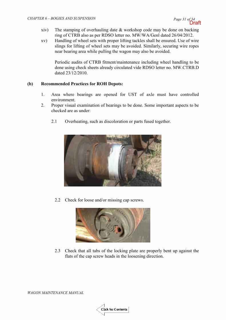
CHAPTER 6 – BOGIES AND SUSPENSION
WAGON MAINTENANCE MANUAL
Page 31 of 34
xiv) The stamping of overhauling date & workshop code may be done on backing ring of CTRB also as per RDSO letter no. MW/WA/Genl dated 26/04/2012.
xv) Handling of wheel sets with proper lifting tackles shall be ensured. Use of wire slings for lifting of wheel sets may be avoided. Similarly, securing wire ropes near bearing area while pulling the wagon may also be avoided.
Periodic audits of CTRB fitment/maintenance including wheel handling to be done using check sheets already circulated vide RDSO letter no. MW.CTRB.D dated 23/12/2010.
(b) Recommended Practices for ROH Depots:
1. Area where bearings are opened for UST of axle must have controlled environment.
2. Proper visual examination of bearings to be done. Some important aspects to be checked are as under:
2.1 Overheating, such as discoloration or parts fused together.
2.2 Check for loose and/or missing cap screws.
2.3 Check that all tabs of the locking plate are properly bent up against the flats of the cap screw heads in the loosening direction.
Draft

CHAPTER 6 – BOGIES AND SUSPENSION
WAGON MAINTENANCE MANUAL
Page 32 of 34
2.4 Inspect for damage or wear to the end cap from a displaced adapter.
2.5 Examine the bearing for welding damage or exposure to extreme heat, such as from a cutting torch. Remove the bearing from service if you find any damage.
2.6 Check for cracked or broken outer rings (also called bearing cups).
Draft

CHAPTER 6 – BOGIES AND SUSPENSION
WAGON MAINTENANCE MANUAL
Page 33 of 34
2.7 Inspect for a loose backing ring. If you can move or rotate the backing ring by hand, remove the bearing from service.
2.8 Check the backing ring for damage or wear from a displaced adapter.
2.9 Check whether the grease seal is displaced or cocked or has external damage.
3. While carrying out wheel turning, the prescribed dummy/protective covers (as mentioned in clause 6.22 & shown in Drawing No. WDIIA-8514/S-1, included in Annexure of G-81) on bearing may be used.
4. Proper tightening of end cap screws with periodically (monthly) calibrated torque wrench at specified torque may be ensured on wheel sets. The specified torque should be maintained to 40 Kg – m (290 foot-pound). The torque wrench must be maintained with an accuracy of +/- 4% (Maximum). Minimum 2 passes and maximum 5 passes to be applied to ensure proper clamping. If any screw movement persists after 5 passes check for any irregularity.
Draft

CHAPTER 6 – BOGIES AND SUSPENSION
WAGON MAINTENANCE MANUAL
Page 34 of 34
5. Handling of wheel sets to be done by using the prescribed lifting tackle and not wire ropes which can damage the grease seals.
6. In case bogie(s) are dismantled for any purpose, the adapter must be thoroughly inspected for soundness and wear. Gauging must be done as specified in G 95.
7. Ensure the Adapter is properly placed on CTRB. Most bearings will “creep” in service, creating two wear bands as pictured below. This is a normal condition that also causes wear to the adapter‟s seat pads
Wear bands that extend to the end of the outer ring, as shown on the left side of the image below, indicate an excessively worn adapter seat. A shiny edge at the extreme end of the outer ring, as shown on the right side of the image below, is an indication that the thrust shoulder is worn. Replace the adapter if either of these conditions exist.
8. Whenever wagons or bogies fitted with CTRBs require welding in ROH Depots/Sicklines, special attention should be paid so that electric current does not pass through the bearings. The earthing should be done very close to welding area and the earthing wire should be tightly secured at both ends. Alternatively the earthing can be done with a earthing wire/strip running parallel to the track instead of earthing with the rails. If wagon is not properly earthed the current passing through the bearings will cause arcing in between the rollers and the raceways leading to failure.
9. The stamping of overhauling date on backing ring of CTRB has been advised to be done by workshops on each overhauled bearing to ensure traceability. In case CTRBs fitted wheel are found to be overdue overhauling in course of ROH/Sick line examination to the wagon, such wheels must be sent to nominated workshop for overhauling.
Draft

CHAPTER 6 – BOGIES AND SUSPENSION
WAGON MAINTENANCE MANUAL
Page 35 of 34
((cc)) RReeccoommmmeennddeedd pprraaccttiicceess dduurriinngg iinnccoommiinngg ttrraaiinn eexxaammiinnaattiioonnss iinn yyaarrddss 1. Detection of warm bearings on arrival of the train. Check operating
temperature of the bearing by touching the adapter or underside of the bearing cup with bare hands immediately after the vehicle is halted. If it is found impossible to hold the hand for a few seconds on the adapter or the cup it means that the bearing is running hot. Cross check the bearing temperature with temperature sensing hand held pyrometers/sensors giving direct reading of the bearing. If bearing temperature is more than 90 degree centigrade the wagon should be detached and bearings should be removed from the service.
2. Check for any abnormal sound and/or grinding noise. 3. Visually inspect the bearing for defects like broken cup, loose or damaged
grease seals, broken adapters, missing cap screws, broken /distorted end cap, broken locking plate. Check for loose backing rings, missing side frame key. Any of these conditions are reasons for bearing removal.
4. Checking of displaced adapters [as mentioned in clause 6.1.1(d) of G-81]. 5. Availability of adapter retaining nut & bolt in wide jaw bogies.
(d) Axle Box Feeling of Freight Trains The procedure of axle box feeling is as under:
1. Axle box feeling should be done immediately after the arrival of the train and two technicians, one from the left and another from the right side should do the job.
2. Axle Box feeling must be done on the adapter or the underside of the CTRB cup.
3. Hand held pyrometers should be used for detecting the temperatures; in addition the practice of feeling the boxes with back side of palms should be followed. Such pyrometers should be calibrated regularly. The wagons with axle boxes having temperature more than 90 Degree Celsius should be detached.
4. The axle boxes having grease oozing, burning small, missing/lose end cap bolts, loose backing rings, grease seals and burnt EM pads are the indicators of potential hot box cases.
The above instructions should be displayed at the axle box feeling points for the guidance of the technicians.
(RDSO Letter No. MW.RB.Genl Dated 20/21.11.2012)
Draft

CHAPTER 7 – AIR BRAKE SYSTEM
WAGON MAINTENANCE MANUAL
Page 1 of 133
((WWAAGGOONN MMAAIINNTTEENNAANNCCEE MMAANNUUAALL-- 22001133))
CHAPTER – 7
AIR BRAKE
SYSTEM
Draft

CHAPTER 7 – AIR BRAKE SYSTEM
WAGON MAINTENANCE MANUAL
Page 2 of 133
CHAPTER 7
AIR BRAKE SYSTEM
701. CLASSIFICATION OF AIR BRAKE SYSTEM
On the basis of type of release, air brake system is classified as:
Direct release air brake system Graduated release air brake system
Both Direct and Graduated release are further available in two forms viz.
Single pipe and Twin pipe
The diagram shown in fig. 7.1 illustrates the schematic layout of air brake equipment on the under frame of freight stock. As shown in figure, the single pipe graduated release air brake system consists of following components:-
i) Distributor valve ii) Common pipe bracket with control reservoir. iii) Auxiliary reservoir.100 Litres & 75 Liters iv) Three way centrifugal dirt collector. v) Isolating cock. vi) Brake cylinder 355mm diameter & 300 mm diameter. vii) Cut off angle cock (32mm size on either ends of brake pipe &
feed pipe). viii) Air brake hose coupling (32mm for brake pipe / 32 mm from
feed pipe). ix) Brake pipe/feed pipe (32mm dia). x) Branch pipes from BP to brake equipment (20mm bore). xi) Guard emergency brake valve. xii) Pressure gauges for BP xiii) Quick Coupling.
Recently, Bogie mounted Brake System (BMBS) has also been introduced for
freight stock. The details of BMBS for freight stocks are given in Para 729 of this chapter
702. PRINCIPLE OF OPERATION OF SINGLE PIPE GRADUATED RELEASE AIR BRAKE SYSTEM Some of the Air Brake goods stock on IR is fitted with single pipe graduated
release air brake system. In single pipe, brake pipes of all wagons are connected. Also all the cut off angle cocks are kept open except the front cut off angle cocks of BP of leading loco and rear end cut off angle cock of BP of last vehicle. Isolating cocks on all wagons are also kept in open condition. Auxiliary reservoir is charged through distributor valve at 5.0 kg/cm2.
Draft

CHAPTER 7 – AIR BRAKE SYSTEM
WAGON MAINTENANCE MANUAL
Page 3 of 133
Fig. 7.1 GRADUATED RELEASE SINGLE PIPE AIR BRAKE SYSTEM
Draft

CHAPTER 7 – AIR BRAKE SYSTEM
WAGON MAINTENANCE MANUAL
Page 4 of 133
A. Charging stage
Fig. 7.2 CHARGING
During this stage, brake pipe is charged to 5kg/cm2 pressure which in turn charges control reservoir and auxiliary reservoir to 5 kg/cm2 pressure via distributor valve. At this stage, brake cylinder gets vented to atmosphere through passage in Distributor valve.
B. Application Stage
Fig. 7.3 APPLICATION
Draft

CHAPTER 7 – AIR BRAKE SYSTEM
WAGON MAINTENANCE MANUAL
Page 5 of 133
For application of brakes, the pressure in brake pipe has to be dropped. This is done by venting air from driver‟s brake valve. Reduction in brake pipe pressure positions the distributor valve in such a way that the control reservoir gets disconnected from brake pipe and auxiliary reservoir gets connected to brake cylinder. This results in increase in air pressure in brake cylinder resulting in application of brakes. The magnitude of braking force is proportional to reduction in brake pipe pressure
Note: 1. Brake Application takes places when Brake pipe pressure is dropped. 2. The drop of pressure may be a) Intentional and b) Accidental.
C) Release stage
Fig. 7.4 RELEASE
For releasing brakes, the brake pipe is again charged to 5 kg/cm2 pressure by compressor through driver‟s brake valve. This action positions distributor valve in such a away that auxiliary reservoir gets isolated from brake cylinder and brake cylinder is vented to atmosphere through distributor valve and thus brakes are released
702A. PRINCIPLE OF OPERATION OF TWIN PIPE GRADUATED RELEASE AIR BRAKE SYSTEM
SSome of the Air Brake goods stock on IR is fitted with Twin pipe graduated release air brake system. In Twin pipe, brake pipes and feed pipes of all wagons are connected. Also all the cut off angle cocks are kept open except the front cut off angle cocks of BP/ FP of leading loco and rear end cut off angle cock of BP and FP of last vehicle. Isolating cocks on all wagons are also kept in open condition. Auxiliary reservoir is charged to 6.0 Kg/cm2 through the feed pipe.
A. Charging stage During this stage, brake pipe is charged to 5 kg/cm2 pressure and feed pipe is charged to 6 kg/cm2 pressure which in turn charges control reservoir and auxiliary reservoir to 6 kg/cm2 pressure. At this stage, brake cylinder gets vented to atmosphere through passage in Distributor valve.
Draft

CHAPTER 7 – AIR BRAKE SYSTEM
WAGON MAINTENANCE MANUAL
Page 6 of 133
BB.. AApppplliiccaattiioonn SSttaaggee For application of brakes, the pressure in brake pipe has to be dropped. This is done by venting air from driver‟s brake valve. Reduction in brake pipe pressure positions the distributor valve in such a way that the control reservoir gets disconnected from brake pipe and auxiliary reservoir gets connected to brake cylinder. This results in increase in air pressure in brake cylinder resulting in application of brakes. The magnitude of braking force is proportional to reduction in brake pipe pressure
Note: 1. Brake Application takes places when Brake pipe pressure is dropped. 2. The drop of pressure may be a) Intentional and b) Accidental.
C. Release stage For releasing brakes, the brake pipe is again charged to 5 kg/cm2
pressure by compressor through driver‟s brake valve. This action positions distributor valve in such a way that auxiliary reservoir gets isolated from brake cylinder and brake cylinder is vented to atmosphere through distributor valve and thus brakes are released.
Do‟s and Don‟ts for Twin Pipe working of Freight Trains
Do‟s: 1. Do ensure that the all twin pipe Wagons are operated in CC rakes only. 2. Do ensure that loco provided for twin pipe rake is having its twin pipe in working
condition. 3. Do ensure availability of spare pool of twin pipe wagon & brake van, for replacement,
if required. 4. Do ensure availability of spare feed pipe in loco. 5. Do ensure that brake van provided for twin pipe working is having twin pipe system. 6. Do ensure BP coupling heads are marked with „BP‟ and painted in green. 7. Do ensure FP coupling heads are marked with „FP‟ and painted in white. 8. Do ensure that BP & FP hose couplings at the rear end of the train are placed on their
respective hose coupling supports. 9. Do ensure that pressure gauges for BP and FP are provided in the brake van. 10. Do ensure that brake pipe/feed pipe angle cocks are not closed under any
circumstance, either for isolation of wagons or for any purpose whatsoever, except for carrying out shunting operation, after which the angel cocks should again be opened to ensure continuity of brake pipe and feed pipe.
11. Do ensure that the isolating cock of feed pipe of all the wagons in the open position. The handle of cock shall be vertically down when open and at horizontal when closed.
12. Do ensure that gauge in guards compartment show pressure not less than 5.8 kg/cm2 in feed pipe after the system is fully charged.
13. Do ensure that feed pipe hose coupling are connected to form a continuous passage from locomotive to last vehicle.
14. Do ensure that feed pipe Cut off angle cocks, except at the rear of train, are kept open. 15. Do ensure availability of the quick coupling for attaching and detaching the pressure
gauges for BP/FP in brake van. 16. Do ensure that the leakage in brake system is less than 0.25kg/cm2 per minute. 17. Do close BP/FP angle cocks of adjacent wagons to uncouple hose couplings.
Draft

CHAPTER 7 – AIR BRAKE SYSTEM
WAGON MAINTENANCE MANUAL
Page 7 of 133
DON‟Ts 1. Do not allow single pipe coupling. 2. Do not allow a feed pipe to be connected to the brake pipe anywhere in the train or
vice versa. 3. Do not allow a feed pipe hose coupling at rear end to dangle. 4. Do not allow train to leave with leakage higher than specified. 5. Do not allow train to leave with feed pipe pressure in loco and brake van less than
specified.
UNCOMMON ITEMS FOR TWIN PIPE AIR BRAKE SYSTEM
Items Description & dimensions Nos./ Wagon
Ref. Drg.
1. AIR BRAKE HOSE COUPLING (F.P.) 2 WD-81027-S-01 2. ISOLATING COCK 1 WD-83062-S-04 3. CHECK VALVE 1 WD-83062-S-03 4. PIPE 20 N.B. 1
Respected different drawings of different
wagons.
5. PIPE 20 N.B. 1 6. PIPE 20 N.B. 1 7. PIPE 32 N.B. (F.P.) 1 8. PIPE 32 N.B. (F.P.) 1
MARKING OF TWIN PIPE AIR BRAKE FITTED WAGONS
For easy identification of these wagons, „Twin Pipe‟ written in black letters on yellow background and encircled in white band shall be marked on side panel, one side in English and other side in Hindi as specified in RDSO drawings.
NOTE: For further details please refer Annexure XIX of G-97 ammandment No. 3 of
Jan. 2010 for “General guidelines for operation and examination of Twin Pipe Air Brake system of complete train” and RDSO repot No. MP. Guide No. 11 (Rev. -01) “Procedure for checking of Diesel/Electric locomotive Hauled Air Braked Trains (Fitted with twin pipe air brake system)”
AIR BRAKE SUB ASSEMBLIES
703. COMMON PIPE BRACKET
Common pipe bracket is permanently mounted on the under frame of a vehicle. The distributor valve along with the intermediate piece (sandwich) which houses the isolating cock is mounted on one face of the common pipe bracket. The control reservoir is mounted on the other face of the Common pipe bracket.
The Common pipe bracket has been evolved with the purpose of making it suitable for use with any make of distributor valve adopted on Indian Railways.
Common pipe bracket is a sturdy casting with internal air passages, matching the intermediate piece mounting face with accurately profiled air cavities and flanged ports leading to the appropriate ports of the distributor valve.
Branch pipes to the brake pipe and brake cylinders are fitted on the appropriate ports on the common pipe bracket. The advantage of fitting a common pipe bracket is to remove the distributor valve for repair or replacement without disturbing the pipe connections.
Draft

CHAPTER 7 – AIR BRAKE SYSTEM
WAGON MAINTENANCE MANUAL
Page 8 of 133
704. INTERMEDIATE PIECE (SANDWICH PIECE)
Intermediate piece serves the purpose of blanking all the other ports on the common pipe bracket front face other than required for a particular make of distributor valve. Each type of distributor valve is mounted on the common pipe bracket with its own intermediate piece (sandwich).
Intermediate piece is mounted on the common pipe bracket face with a
common gasket and the distributor valve is fastened to the intermediate piece. Isolating cock for distributor valve, which is housed in the intermediate piece is for isolating the distributor valve in case of malfunctioning or for disconnecting the brake pipe pressure. Isolating cock on intermediate piece has a built in venting arrangement.
705. BRAKE PIPE HOSES
Fig. 8.5
In order to connect two successive wagons, the brake pipes (BP) & Feed Pipe (FP) installed on the underframe are fitted with flexible hoses. The hoses are named as BP/FP hose.
706. BRAKE PIPE COUPLING
To connect subsequent wagons, the hoses of BP are screwed to coupling and hose nipple by means of stainless steel `Bend it‟ type clips. The coupling is specially designed in the form of palm end and hence also known as palm end coupling. For easy identification the couplings are engraved with letter BP and coupling heads are painted green
Note: Design, controlling dimensions, material and specification of components
shall conform to the latest revision of RDSO drg. No. SK-73547 for BP, WD-81027-S-01 for FP and appendix F of 02 ABR 02 of RDSO specification.
The air brake hose couplings are provided in the brake pipe line throughout the train for connecting the brake pipe of adjacent wagons to form the complete rake. Each Air Brake Hose coupling consists of a specially manufactured rubber hose clamped over a nipple on one end and a coupling head on the other end. Rubber sealing washers are provided on the outlet port of the coupling head. Since a joint is formed at the coupling head, leakage may take place, through it. Therefore it is necessary to subject the hose coupling of brake pipe to leakage test.
Draft

CHAPTER 7 – AIR BRAKE SYSTEM
WAGON MAINTENANCE MANUAL
Page 9 of 133
A. TOOLS AND EQUIPMENTS
a) Test stand (Fig. 7.6)
Test stand for testing of the hose coupling consists of the following main equipment
1) Supply of compressed air at – 10 Kg/cm2 2) Isolating cock – 1a and 1b 3) Exhaust cock – 1c 4) Main reservoir 5) Pressure gauge
6a for main reservoir 6b for flexible hose
6) Flexible hose - for connecting hose coupling for immersing in to water. 7) Water tub with safety cage – for checking leakage from hose coupling. 8) Dummy coupling head.
b) TEST PROCEDURE
For testing the hose coupling the steps given below should be followed:
i. Use a dummy coupling head to block the outlet port of the hose coupling. ii. Connect to hose coupling under test to the end of flexible hose. iii. Open isolating cock 1(a) iv. Adjust pressure regulator (2) so that pressure gauge (6a) shows 10Kg./cm2 air
pressure. v. Immerse the hose coupling assembly completely in the tub of water. vi. Open isolating cock (1b) and see that (6b) shows 10 Kg/cm2 pressure. vii. Observe leakage, if any from all parts of the hose coupling. viii. Close the isolating cock 1(b). ix. Disconnect the hose coupling from test bed. x. If the leakage is observed through the coupling head, replace the gasket and
test again. xi. If leakage persists even after change of gasket the coupling head is
unserviceable and complete assembly shall be rejected. However if leakage occurs at the hose nipple or coupling end hose joint the clamp should be attended/replaced to make the assembly leak proof.
c) SAFETY PRECAUTIONS
Specified tools and fixtures should be used for connecting and disconnecting the hose coupling with the air supply.
While testing the hose coupling before charging it to 10kg/cm2 pressure, the tube should be covered and locked with a protective cage.
Exhaust the pressure from the hose coupling under test, before lifting the safety cage and uncoupling it.
After testing, the hose assembly shall be stored in a dry and clean space. The inlet and outlet port must be plugged with protective cap to prevent entry of dust and foreign particles inside the hose coupling.
Draft

CHAPTER 7 – AIR BRAKE SYSTEM
WAGON MAINTENANCE MANUAL
Page 10 of 133
1 ¼
“ B
SB S
OC
KET
TO
CO
UPL
E H
OSE
C
OU
PLIN
G
NIP
PLE
END
FLEX
IBLE
HO
SE
HIG
H P
RES
SUR
E (1
0 K
G/C
M2 C
AL)
CH
AR
GIN
G
PRES
SUR
E G
AU
GE
EXH
AU
ST
CO
CK
1c
ISO
LATI
NG
C
OC
K
6b
MA
IN
RES
ERV
OIR
6a
MR
1b
2
1a
ISO
LATI
NG
C
OC
K
PRES
SUR
E R
EDU
CER
Fig.
7.6
TE
STIN
G O
F H
OSE
CO
UPL
ING
Draft

CHAPTER 7 – AIR BRAKE SYSTEM
WAGON MAINTENANCE MANUAL
Page 11 of 133
707. CUT OFF ANGLE COCK
Fig. 7.7
Cut off angle cocks are provided on the air brake system to facilitate coupling and uncoupling of air hoses (i.e. brake pipe). When the handle of the cut off angle cock is placed in closed position it cuts off the passage of compressed air, there by facilitating coupling and uncoupling action.
If coupling action has to be performed on a given rake, ensure that the cut off angle cock provided at the end of the brake pipes are closed. By doing this the compressed air gets cut off and does not enter into the brake pipe air hose . The air hoses without compressed air can thus easily be coupled without any jerk. Similarly during uncoupling the cut off angle cocks of subsequent wagons should be closed. By doing so the air present in the brake pipe air hose gets leaked through the vent provided in the body of the cut off angle cock. Finally the air hoses get emptied and thus can be easily uncoupled without any jerk.
The cut off angle cock consists of two parts viz. cap and body which are secured together by bolts. The cap and the body together hold firmly the steel ball inside it, which is seated on rubber seat. The ball has a special profile with the provision of a groove at the bottom portion for venting the air to the atmosphere.
On the top surface of the body a bore is provided for placing the stem, to which a self locking type handle is fixed. When the handle is placed parallel to the cut off angle cock the inlet port of the cut off angle cock body is connected to the outlet port, through the hole provided in steel ball. Thus air can easily pass through the cock. This position of the handle is known as open position. When the handle is placed perpendicular to the cock body the steel ball gets rotated and the spherical and groove portion of the ball presses against the sealing ring at inlet and outlet port, there by closing the passage of inlet air and venting the outlet air through the vent hole. This position of the handle is known as closed position.
With the stem one leaf spring is provided which presses the operating handle downwards. By virtue of this, handle gets seated in deep grooves at ON/OFF position resulting in a mechanical lock.
Under normal working conditions, the handle of all cut off angle cock of BP are kept open except the rear end angle cock (BP). This facilitates in charging the complete air brake system with compressed air supplied by the compressor housed in the locomotive. Cut off angle cock fitted on the brake pipe is painted green.
Draft

CHAPTER 7 – AIR BRAKE SYSTEM
WAGON MAINTENANCE MANUAL
Page 12 of 133
Note: The dimension and tolerances of cut off angle cock shall be as indicated in latest revision of RDSO drawing nos. WD-88123-S-01 and WD-88123-S-02.
Since a number of manufacturers exist for air brake equipment and component, refer to concerned original manufacturer‟s maintenance manual for part no. and description of spares.
A. OVERHAULING OF CUT OFF ANGLE COCK
These angle cocks are of ball-type ensuring better sealing against leakage and facilitate ease of operation. During overhauling, it is dismantled for cleaning, replacement of parts and checking for effective functioning. The cut-off angle cock is to be completely dismantled and overhauled during POH or when there is some specific trouble.
a) TOOLS & EQUIPMENT
The following tools and fixtures are required for overhauling
(I) Single end spanner. 1) A/F 17 for M10 nut pivot screw. 2) A/F 10 for M6 nut.
(II) Screw driver 12”/300 mm long. (III) Vice. (IV) Light hammer.
b) PROCEDURE Dismantling
Hold the cut – off angle cock in vice. Unscrew the lock nut from the stem. Take out the handle assembly (The handle assembly need not be
dismantled further unless it is necessary to change the plate spring i.e. if it is found, heavily rusted, pitting crack or the spring is permanent set).
Unscrew the four hexagonal bolts and spring washers. Detach cap from the body. Remove „O‟ ring and ball seat from the cap. Turn the stem in such a way that the ball can be pulled from the stem. Slightly hammer the stem at its top and take out the stem through the
bore of the body. Remove the ball seat from the body.
c) Cleaning of Parts
Clean out side portion of the body and cap with wire brush. Direct a jet of air to remove the dust. Clean all metallic parts with kerosene oil and wipe dry.
d) Replacement of Parts
Replace all rubber parts. Replace spring-washer, nut & bolts in case they are excessively corroded
or defective.
Draft

CHAPTER 7 – AIR BRAKE SYSTEM
WAGON MAINTENANCE MANUAL
Page 13 of 133
Replace handle spring if it is found heavily rusted, is having pitting crack or is permanently set (Dismantle the handle assembly, and fit a new spring along with a snap head rivet).
Replace stainless steel ball if found with scratch marks on the outer surface or dented.
e) Assembly
Insert the two „O‟ rings in their respective grooves on the stem. Keeping the threaded end of the stem first, insert the stem into the body
through the bore of the body. Place one ball seat in its groove inside the body. Position the ball after correctly aligning its venting slot in the bore of the
body. Place the second ball seat and „O‟ ring in their respective positions on the
cap. Secure the body and cap by Hex. Hd. Bolt (M6) and spring washer (for
M6). Place the handle assembly on the stem and secure it with Hex. Hd. Nut
(M10). During assembly apply a light coat of shell MP2 or equivalent grease on
the external surface of the threads and the ball. B. TESTING OF CUT–OFF ANGLE COCK a) TOOLS AND EQUIPMENT
i. Test Bench ii. Compressor to build pressure more than 10 kg/cm2. iii. Single ended spanner as per IS 2027
a) Across face 17 (for M10 lock nut) - 1 No. b) Across Face 13 (for M8 studs) 2 No.
iv. Screw Driver –300mm, 1 No. v. 1 ¼ “ BSP dummy Plug with seal. vi. Dummy plug for angle cock.
b) TEST PROCEDURE
Following test procedure should be adopted step by step for performing the leakage test.
i. Mount the angle cock on the base of the test bench (Part No. 7 of the figure of the test bench).
ii. Move the handle to the closed position. iii. See that cock (1e) and (1c) are in closed position. iv. Now open cock 1(a) and 1(b) till MR indicates a pressure of 10 Kg/Cm2. v. If necessary, adjust pressure regulator (2) to maintain the pressure at 10
kg/Cm2. vi. Open cock (1c) and check the leakage with soap solution. There should not
be any leakage. vii. Check pressure drop in gauge (6b) there should not be any leakage from
flange joints, vent and outlet port of the angle cock. viii. Close cock (1c) and tighten the dummy plug and seal the outlet of the angle
cock.
Draft

CHAPTER 7 – AIR BRAKE SYSTEM
WAGON MAINTENANCE MANUAL
Page 14 of 133
ix. Move the handle to the open position. Open cock 1c. x. Check for leakage from body and cap joint, vent and all over the stem
periphery using soap water. No leakage is permissible. xi. Move the handle to closed position and notice a short blast of air through
the vent. xii. Close cock 1c then Open cock (1d) and exhaust the pressure to zero. xiii. Remove the angle cock. xiv. Report results of the test.
c) SAFETY PRECAUTIONS
Specified tools and fixtures should be used for assembly and disassembly
operations.
The small metal parts like leaf spring, nut, bolts, washers, screws etc should be kept in a safe place and replaced in case found defective.
Inlet and outlet port of the tested angle cock should be plugged with
protection cap to prevent entry of dust and moisture inside the cut off angle cock.
Ball should be handled carefully to avoid any damage on its surface.
Threaded portion of body and cap should not be damaged at the time of
dismantling. 77008. BRAKE CYLINDER
(Note: Anti-rattler ring shall be provided on brake cylinder for passenger stock)
Fig. 7.8 BRAKE CYLINDER
On every wagon fitted with air brake system one brake cylinder is provided for actuating the brake rigging for the application and release of brakes.
Draft

CHAPTER 7 – AIR BRAKE SYSTEM
WAGON MAINTENANCE MANUAL
Page 15 of 133
During application stage the brake cylinder receives pneumatic pressure from the auxiliary reservoir after being regulated by the distributor valve. There after the brake cylinder develops mechanical brake power by outward movement of its piston assembly. To transmit this power to the brake shoe, the push rod of piston assembly is connected to the brake shoe through a system of levers to amplify and transmit the brake power. During release action of brakes the compression spring provided in the brake cylinder brings back the rigging to its original position.
The cylinder body is made out of sheet metal or cast iron and carries the mounting bracket, air inlet connection, ribs and flange. To the cylinder body, a dome cover is fitted with the help of bolts and nuts. The dome cover encloses the spring and the passage for the piston trunk, which is connected to the piston by screws. The piston is of cast iron having a groove in which piston packing is seated. Piston packing of rubber material which is of oil and abrasion resistant and unaffected by climatic changes. It is snap fit to the piston head and has self lubricating characteristic which ensures adequate lubrication over a long service period and extends seal life considerably
The piston packing also seals the air- flow from the pressure side to the other side and is guided by the wear ring. The wear ring prevents the friction between cylinder body and the piston head. The piston sub assembly incorporates a push rod, which can articulate and take minor variations in alignment during fitment/operation.
Note: The dimension and tolerances of brake cylinder shall conform to the latest revision of
RDSO drawing number WD-92051–S 06, WD-92051-S-07, WD-92051-S-08, WD-92057-S-09, WD 92051 –S-09, WD 94048-s-01, WD 92051 –S-11, WD 92051 –S-12, WD 92051 –S-13, WD 92051 –S-14 and WD 92051 –S-15.
A. OVERHAULING OF BRAKE CYLINDER
Brake cylinder has to be thoroughly overhauled for efficient and reliable trouble free performance during its prolonged service life. The complete overhauling of the brake cylinder is to be carried out during POH or when there is some specific trouble.
a) TOOLS & EQUIPMENT
Sr. No. Description
1. Torque Wrench 0-3 Kg range 2. Double End Spanner 24x27 mm across face (For M16) 3. Double End Spanner across face 13x14 (For M12) 4. Socket Wrench 19 mm (For M12) 5. Screw Driver 12" (300 mm) 6. Special fixture (Screw press/ Pneumatic) 7. Gauge for examining bore of the cylinder
b) Dismantling of Brake Cylinder
Before dismantling the dome cover insert a rounded head pin of 12x25 long and secure one of the hole in the piston trunk for the purpose of safety to prevent dome cover working out of the piston rod due to the cylinder return spring force while opening the dome cover with the help of a special fixture clamp the dome cover.
Draft

CHAPTER 7 – AIR BRAKE SYSTEM
WAGON MAINTENANCE MANUAL
Page 16 of 133
Unscrew the Hex. Hd. nut and take out the spring washer on the dome cover.
Turn the handle of the fixture to release the clamp and withdraw the holding clamp of the fixture till the return spring inside the cylinder is fully expanded and free.
Remove the dome cover and take out the return spring. Remove the bush on the rod and brake cylinder. Remove the piston rod sub-assembly, piston ring packing, wear ring and
slide out the anti rattler ring from the piston rod. Unscrew the CSK, head screw and separate the piston, pin, piston trunk &
piston rod assembly. Unscrew the brake cylinder plug at the rear end.
c) Cleaning of Parts
Blow a jet of air to clean the dust on the external surface. Clean the metallic parts using wire brush and kerosene oil. Clean the internal parts with nylon bristle brush. Clean piston packing, wear ring and rubber parts with soap water solution.
d) Replacement of Parts
Replace return spring in case of crack, kinks or permanent set. Replace the brake cylinder body if found with deep marks, heavily
corroded, or the bore is worn uneven or having ovality. Replace all rubber parts. If piston trunk is worn excessively it should be replaced. Replace piston and piston rod for damages, bent etc. Replace dome cover for damage, damaged hole etc.
e) Inspection and Repairs of the Parts
Examine visually that the internal surface is free from scratches, rust. Brake cylinder bore to be checked for ovalness with proper gauge. Check the characteristics of the return spring. Piston trunk to be checked for wear and tear. Pin, piston rod should be checked for wear. Dome cover shall be checked for excessive wear and if worn build up
with welding and thereafter re-bore to the required size. Gauge bush bore of the piston rod, replace it if worn.
f) Testing Of Brake Cylinder Body for Leakage
Before assembly, put dummy plate on the dome side and subject the brake cylinder for hydraulic pressure of 10 kg/cm2 for 5 minutes. No leakage is permitted.
g) Assembly of Brake Cylinder
Assemble piston rod, pin, and piston trunk on piston, tighten CSK screws to piston trunk and piston.
Slide anti-rattler ring from the piston front side. Assemble piston return spring on the piston head and insert the dome
cover over the piston trunk. Insert 12 x 25 mm long head pin into the hole provided in the extended
Draft

CHAPTER 7 – AIR BRAKE SYSTEM
WAGON MAINTENANCE MANUAL
Page 17 of 133
portion of the trunk. Smear the piston head & inside the cylinder body with MP 2 grease or
equivalent. Ease the packing into the cylinder with a wooden spatula with a round
nose and round edge to avoid damage to the piston packing. Push the piston assembly approximately to the central position of the
cylinder. With the help of special fixture, bring down the dome cover on to the
cylinder body and fasten the 8 Hex. HD bolt, nut and spring washer with required torque.
Take out the 12x25 long pin from the piston trunk hole. Fit back the plug at the rear of the cylinder. Fit the new piston packing and wear ring.
B. TESTING OF BRAKE CYLINDER a) BRAKE CYLINDER TEST BENCH (Fig. 7.9)
Test bench consists of the following main parts i. 3 nos. of isolating cocks ii. Isolating cock with 1mm choke iii. Pressure reducing valve
Fig. 7.9 TEST BENCH FOR BRAKE CYLINDER
iv. 2 Nos. Pressure gauges v. Pipe line filter vi. Brake cylinder pressure mounting base with safety guard vii. Air reservoir
b) TOOLS REQUIRED DURING TESTING
i. Torque wrench range (2-3 kgM capacity) – One number. ii. Double ended spanner (M16) across face 24x27 – One number. iii. Socket wrench (M12) across face 19 – One Number. iv. Double ended spanner (M8) across face 13x14 – One number. v. Screw Driver – 300mm – One number.
Draft

CHAPTER 7 – AIR BRAKE SYSTEM
WAGON MAINTENANCE MANUAL
Page 18 of 133
After the overhauling of the brake cylinder, it is mounted on the test bench and tested. It should be operated a few times on the test bench to ease the piston. Each brake cylinder after its maintenance and overhaul shall be subjected to the following tests on the test bench.
Arrangement as shown in Fig. 7.9 is used for testing.
c) STRENGTH TEST
Follow the procedure as given below.
i. Place the brake cylinder on base (4) and connect the line to brake cylinder. Brake cylinder stroke should be free.
ii. Close the safety guard, close the cock (Ic). iii. Open cock (1b) and let reservoir pressure reach 10 Kg/cm2. Check the
pressure in MR gauge (3a). iv. Open cock (2) till the pressure reaches 6 Kg/cm2 in pressure gauge
(3b). v. Close the cock (2) and wait for 2 minutes. vi. Open cock (1c).
The above test should be done with the safety guard.
d) PRESSURE TIGHTNESS TEST Follow the following procedure.
i. Mount the cylinder on the test stand and tighten the mounting bolts &
nuts. ii. Set the brake cylinder stroke at 85 + 10 mm. iii. Open cock (2) and let the pressure gauge (3b) reaches 0.8 Kg/cm2. iv. Close the cock (2) and wait for 1 minute till the pressure stablise in
gauge (3b). v. Check for the pressure drop which should not be more than 0.1 Kg/cm2
in 10 minutes. vi. Open cock (1 c) vii. Repeat the test at 130 + 10 mm piston stroke and 3.8 Kg/cm2pressure.
Close cock (2) open cock (1c). Remove the brake cylinder.
If pressure is not correct or leakage rate is higher, dismantle the brake cylinder and examine piston packing wear ring for proper fitment. Examine plug for leakage. Reassemble the components and retest.
e) PAINTING
The exterior of the brake cylinder shall be painted with black enamel paint.
f) STORING
Assembled or dismantled brake cylinder should be stored in such a way to prevent the following.
Flange surface should be prevented from damages. Inlet and outlet port should be plugged with protective cap to prevent the
entry of dust and moisture inside the brake cylinder.
Draft

CHAPTER 7 – AIR BRAKE SYSTEM
WAGON MAINTENANCE MANUAL
Page 19 of 133
g) PRECAUTIONS DURING TESTING
Safety Guard should be used during the strength test. Assembled or dismantled brake cylinder should be stored in such a way to
prevent the following:
i. Flange surface should be prevented from damage. ii. Inlet port should be plugged with a protective cap to prevent the entry
of dust and moisture inside the brake cylinder.
Avoid damage to piston packing by dull or sharp edged thin bladed tool. Fit 12 dia, 25 mm long round headed pin on the hole provided in the extended
portion of trunk surface before loosening the cover bolts. Excessive lubrication of the cylinder must be avoided. Specified tools and fixtures should be used for handling, mounting and
removing the brake cylinder from the test bench. The small metal parts like springs, washer, screws, nuts, bolts, washers should
be kept in a safe place and replaced in case found defective.
709. DIRT COLLECTOR A. FUNCTION OF DIRT COLLECTOR
Dirt Collector is placed in the brake pipe line at a point from where a branch is taken off to the distributor valve. As the name indicates the purpose of the dirt collector is to protect the distributor valve and the auxiliary reservoir by trapping dust and other foreign matters from the compressed air before it enters into the distributor valve and the auxiliary reservoir. This action is achieved by centrifugal action. Hence it is also known as centrifugal dirt collector. The dirt collector ensures inter vehicular full flow of dirt free compressed air to the auxiliary reservoir and the distributor valve through the branch pipes. When the air enters into the body of the dirt collector tangentially through port `A‟ it passes down through inverted case in a spiral path. Due to the velocity of air flow, dirt particles get flung outwards. There after they slide down & collect at the bottom.
B. SALIENT FEATURES OF DIRT COLLECTOR
The air entering into the dirt collector from the brakepipe is guided through suitably shaped passage in dirt collector body to produce centrifugal flow. The air is then filtered through additional filter assembly before it is passed to outlet on branch pipe side to provide dust proof air to the distributor valve /auxiliary reservoir after arresting fine dust particles. The dirt contained in the air descends down and gets deposited in the dirt chamber. However, fine particles are also arrested in the filter assembly. The dust particles accumulated in the dirt chamber are removed by opening the drain plug. Rubber gasket is provided between the cover and housing to prevent leakage. Similarly leather washer is provided between the housing and the drain plug to prevent leakage.
Note: The dimensions and tolerance of dirt collector shall be as indicated in
latest revision of RDSO drawing number WD-92051-S-03, WD-92051-S-04 and WD-92051-S-05.
The dirt collector is to be completely dismantled and overhauled once in 5 years or after 8 lakhs kilometers whichever is earlier or when there is some specific trouble.
Draft

CHAPTER 7 – AIR BRAKE SYSTEM
WAGON MAINTENANCE MANUAL
Page 20 of 133
C. TOOLS AND FIXTURES
The following tools and fixtures are required for overhauling:
a) Spanner 19 x 22mm b) Vice. c) Screw Driver
D. PROCEDURE FOR MAINTENANCE
I. Disassembly
Hold the dirt collector in vice. Loosen drain plug and remove it completely from housing. Remove top cover and seal by loosening four hexagonal nuts and
removing hexagonal bolts. Remove filter from body.
II. Cleaning of Parts
Clean all metallic parts using brush and kerosene oil. Clean filter with soap water. Check all parts for any damage.
III. Replacement of Parts
Replace sealing ring and gasket. Replace filter if found punctured or damaged. Check spring washer and replace in case defective or excessively
corroded.
IV. Assembly
Assemble body after smearing grease. Locate filter in position and assemble top cover with new gasket. Fix hexagonal bolts/nuts along with the spring washer. Fix new sealing ring to the bottom and assemble drain plug.
E. TESTING OF DIRT COLLECTOR
Centrifugal Dirt Collector is provided at the junction of the main pipe and branch pipe in brake pipes. There are three purposes for providing the dirt collector.
i. To ensure inter-vehicular full flow of brake pipe lines. ii. For branching and feeding to the distributor valve. iii. To remove dust and scale particles from the air prior to entering the
distributor valve and the air reservoir.
As Dirt collector is subjected to high air pressure it has to be tested for the leakage and strength. Testing of dirt collector is needed after its overhauling. There may be various causes due to which overhauling and subsequent testing of the dirt collector is required.
Draft

CHAPTER 7 – AIR BRAKE SYSTEM
WAGON MAINTENANCE MANUAL
Page 21 of 133
F. TOOLS AND EQUIPMENT
Test Bench (Fig. 7.10) Compressor, capable of building air pressure up to 10 kg/sq. cm. Double ended spanner (Across Face 19x22) – One No. Dummy flange for dirt collector – 2 nos.
G. TEST PROCEDURE
Each dirt collector after overhauling and maintenance should be subjected to pressure test as below:
i. Mount the dirt collector on base of the test bench. ii. Keep cocks ( 1f), (1c) and 1(e) closed. iii. Open cock (1a) and (1b). iv. Charge the reservoir (5) to 10 kg/cm2. v. Close two openings on the dirt collector using dummy flanges. vi. Open cock (1e), check the pressure at (6c). It should be equal to 10
kg/sq. cm. vii. If not develop pressure up to 10 kg/cm2 by adjusting pressure
regulator(2). viii. Close cock ( 1e) ix. Check for leak over the body and joints with the help of soap solution,
no leak is permitted. x. Also check for pressure drop in gauge 6(c)- for 3 minutes xi. Pressure in the gauge 6c should be maintained. xii. Reduce the pressure in the main reservoir (5) to 5 kg/cm2 by opening
cock (1f) and adjusting the pressure regulator (2). xiii. Close cock (1f) as soon as pressure reaches upto 5 kg/cm2. xiv. Remove the dummy flange from the outlet port (which feeds to the
distributor valve). xv. Check for free flow of air from the outlet port. (If air is not flowing
freely it means that the filter is choked). xvi. The pressure will soon exhaust through the outlet port. xvii. Remove the dirt collector from the test stand. xviii. Report Results.
H. SAFETY PRECAUTIONS
a) The assembled dirt collector should be stored in such a way to prevent the
following: b) Flange surface should be prevented from damage. c) Inlet and outlet port should be plugged with protective caps to prevent the
entry of moisture and dirt inside the dirt collector. d) Specified tools and fixtures should be used for handling, mounting and
removing the dirt collector from the test bench. e) The small metal parts like screws, nuts, bolts, washers etc. should be kept
in a safe place and replaced in case found defective,
Draft

CHAPTER 7 – AIR BRAKE SYSTEM
WAGON MAINTENANCE MANUAL
Page 22 of 133
2
`
I.C.
AIR RESERVOIR 40 LITRE
I.C.
PRESSURE REGULATOR
OIL SEPARATOR MR PRESSURE. GAUGE
I.C.
I.C.
I.C.
I.C.
PR. GAUGE
PR. GAUGE
I.C. – ISOLATING COCK
BASE FOR AC
BASE FOR IC/DC/CV/GVV
5a
1e
1f
7
1d
1c
5b
6
4
1b 3 2 1a
5c
Fig. 7.10 TEST BENCH FOR ANGLE COCK & DIRT COLLECTOR
Draft

CHAPTER 7 – AIR BRAKE SYSTEM
WAGON MAINTENANCE MANUAL
Page 23 of 133
710. AUXILIARY RESERVOIR A. FUNCTION
Auxiliary reservoir is actually a pressure vessel and its function is to feed dry compressed air to the brake cylinder for application of brakes.
B. SALIENT FEATURES
The auxiliary reservoir is a cylindrical vessel made of sheet metal. On both the ends of the reservoir, flanges are provided for pipe connection. One end of the auxiliary reservoir is connected to the brake pipe through the distributor valve. Auxiliary reservoir is charged through the brake pipe. The auxiliary reservoir is charged to 5kg/cm2 pressure, charging from the brake pipe through Distributor valve. At the bottom of the auxiliary reservoir, drain plug (or drain cock) is provided for draining out the condensate/moisture.
Note: The dimension & tolerances of the auxiliary reservoir shall be as
indicated in latest revision of RDSO drawing WD-92051-S-01 for 100 lit. Capacity and RDSO drawing number WD-92051-S-02 for 75 lit. capacity.
The auxiliary reservoir is to be completely dismantled and overhauled during
POH or if there is some specific trouble. C. TOOLS AND EQUIPMENT a) Spanner A/F 19x22. b) Light hammer D. PROCEDURE FOR MAINTENANCE DISMANTLING Unscrew the drain plug or drain cock. Drain the water accumulated in the tank. CLEANING OF PARTS Examine the outer surface for any pitting scales or rusting. Clean the exterior of the auxiliary reservoir with a wire brush. Pour kerosene oil in to the auxiliary reservoir and roll few times and
drain the oil. Dry the interior of the reservoir with a jet of air. Rinse the reservoir with RUSTO-LINE and then with ESSO-RUST 392
or equivalent. Clean the drain plug with a wire brush. Auxiliary reservoir shall be painted on the exterior with two coats of zinc
chromium primer and two coats of black enamel.
Draft

CHAPTER 7 – AIR BRAKE SYSTEM
WAGON MAINTENANCE MANUAL
Page 24 of 133
REPLACEMENT OF PARTS Replace the plug washer. Replace the plug if threads are rusted or damaged. Replace the reservoir having deep cuts on surface.
ASSEMBLY Assemble the drain plug with washer by screwing it back into its position. E. TESTING OF AUXILIARY RESERVOIR Air Pressure Test Block one side passage of the auxiliary reservoir with dummy flange. Admit air pressure from the other side passage at 10 Kg/cm2. Check the leakage at the weld seams, with soap water solution. No leakage is permitted.
Hydraulic Test With a hydraulic pump, apply a pressure of 16 Kg./cm2 from one
flange end after blocking the opposite end. Hold the pressure for 5 minutes. Check for the leakage on the external surface of the reservoir by
gently tapping on the weld seams with a light hammer. No leakage is permitted. Drain out the water completely and allow the reservoir to dry, by
directing a jet of air.
F. SAFETY PRECAUTIONS
Specified tools and fixtures should be used for assembly and dismantling operations.
Rubber / leather components should be stored in a safe place away from heat, alcohol & acids. All metal parts like washers should be kept in a safe place.
711. GUARD'S EMERGENCY BRAKE VALVE
Guard's emergency brake valve is provided in the guard„s compartment. This valve provides a facility to the guard to initiate brake application in case of any emergency.
Guard‟s emergency brake valve is connected to the brake pipe. This valve is actually placed in the guard‟s compartment so that in case of an emergency, the guard of the train can communicate to the driver of the train by operating the valve provided in the brake van. When the handle of the guard‟s emergency brake valve is placed parallel to the pipe, the air from the brake pipe is exhausted to the atmosphere. However, to restrict the excessive drop of air pressure in the brake pipe, a choke of 5mm is provided in this valve. This drop in pressure in the brake pipe can also be observed in the air flow meter provided in the locomotive cabin and finally the driver applies the brakes for stopping the train. The handle of the guard‟s emergency brake valve has to be reset manually to normal position before the brake pipe pressure is to be recharged.
Draft
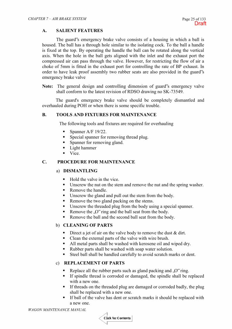
CHAPTER 7 – AIR BRAKE SYSTEM
WAGON MAINTENANCE MANUAL
Page 25 of 133
A. SALIENT FEATURES
The guard‟s emergency brake valve consists of a housing in which a ball is housed. The ball has a through hole similar to the isolating cock. To the ball a handle is fixed at the top. By operating the handle the ball can be rotated along the vertical axis. When the hole in the ball gets aligned with the inlet and the exhaust port the compressed air can pass through the valve. However, for restricting the flow of air a choke of 5mm is fitted in the exhaust port for controlling the rate of BP exhaust. In order to have leak proof assembly two rubber seats are also provided in the guard‟s emergency brake valve
Note: The general design and controlling dimension of guard‟s emergency valve
shall conform to the latest revision of RDSO drawing no SK-73549.
The guard's emergency brake valve should be completely dismantled and overhauled during POH or when there is some specific trouble.
B. TOOLS AND FIXTURES FOR MAINTENANCE
The following tools and fixtures are required for overhauling
Spanner A/F 19/22. Special spanner for removing thread plug. Spanner for removing gland. Light hammer Vice.
C. PROCEDURE FOR MAINTENANCE
a) DISMANTLING
Hold the valve in the vice. Unscrew the nut on the stem and remove the nut and the spring washer. Remove the handle. Unscrew the gland and pull out the stem from the body. Remove the two gland packing on the stems. Unscrew the threaded plug from the body using a special spanner. Remove the „O‟ ring and the ball seat from the body. Remove the ball and the second ball seat from the body.
b) CLEANING OF PARTS
Direct a jet of air on the valve body to remove the dust & dirt. Clean the external parts of the valve with wire brush. All metal parts shall be washed with kerosene oil and wiped dry. Rubber parts shall be washed with soap water solution. Steel ball shall be handled carefully to avoid scratch marks or dent.
c) REPLACEMENT OF PARTS
Replace all the rubber parts such as gland packing and „O‟ ring. If spindle thread is corroded or damaged, the spindle shall be replaced
with a new one. If threads on the threaded plug are damaged or corroded badly, the plug
shall be replaced with a new one. If ball of the valve has dent or scratch marks it should be replaced with
a new one.
Draft

CHAPTER 7 – AIR BRAKE SYSTEM
WAGON MAINTENANCE MANUAL
Page 26 of 133
d) ASSEMBLY
Place seat ring in its position in the bore of the body on one side. Apply grease lightly on the ball. Fit „O‟ rings on the spindle. Insert the ball in the bore of the body in such a way that the ball sits on
the seat ring and the groove seat for spindle is in top position. Insert the spindle with „O‟ rings such that the spindle enters in to the
groove. Screw the gland in to the body. Insert the second seat ring through the bore of the housing. Fit „O‟ ring on the threaded plug. With a special tool screw the
threaded plug. Screw the threaded plug along with the „O‟ ring into the housing till the
ball seat touches the ball. The handle shall be put on the spindle and tightened with spring
washer and nut.
D. TESTING OF GUARD‟S EMERGENCY BRAKE VALVE
After overhauling, fix the valve to the test bench. Put the handle of the valve in off position (close position). Charge the inlet port with a pressure of 10Kg./cm2. Check for leakage on the spindle portion and on the exhaust port with
soap water solution. No leakage is permitted. Operate guard‟s emergency brake valve, by putting the handle in open
position. Air should escape through the vent of the valve.
E. QUICK COUPLING ARRANGEMENT
For fitment of gauge an arrangement for quick coupling is provided. The figure shows the arrangement. The quick coupling when assembled with and without plug shall be leakproof when tested upto 10 kg/cm2 air pressure.
Details of part nos are as under; 1. Plug 8. Valve 2. Locking nut 9. Valve Seat 3. Locking Ring 10. Valve 4. Spring 11. Lower Body 5. Body Top 12. Spring 6. Locking Bush 13. Spring 7. Seal 14. Ball 3.5
Draft

CHAPTER 7 – AIR BRAKE SYSTEM
WAGON MAINTENANCE MANUAL
Page 27 of 133
712. SLACK ADJUSTER A. SALIENT FEATURES
Slack adjuster (also known as brake regulator) is a device provided in the brake rigging for automatic adjustment of clearance/slack between brake blocks and wheel. It is fitted into the brake rigging as a part of mechanical pull rod. The slack adjuster is double acting and rapid working i.e. it quickly adjusts too large or too small clearance to a predetermined value known as `A‟ dimension. The slack adjuster maintains this `A‟ dimension throughout its operation. The slack adjuster, type IRSA-600 & IRSA - 750 used on wagons is composed of the following parts
Adjuster spindle with screw thread of quick pitch (non self locking)
Traction unit containing adjuster nut, adjuster tube and adjuster ear etc.
Leader nut unit containing leader nut and barrel etc.
Control rod with head. The out standing features of slack adjuster IRSA-600 & IRSA - 750 are:
(I) Fully Automatic Once initially set, no manual adjustment is further necessary at any time during its operation. (II) Double-Acting The brake shoe clearance is adjusted to its correct value both ways, either when it has become too large (owing to wear of the brake shoes and wheels) or when it has become too small (e.g. owing to renewal of `worn out brake blocks‟).
(III) Rapid Working Correct brake shoe clearance is automatically restored after one or two applications of the brake. Verification If resistance occurs early in the brake application, caused by heavy brake rigging, e.g. an ice coating on the brake shoes, etc., in such cases the IRSA does not pay out slack immediately, but indexes the amount of slack to be paid out. If the slack really is too small, the IRSA will pay out this indexed slack at the next brake application. Thus false pay-out will not occur.
True Slack Adjuster The slack adjuster adjusts incorrect slack only, thus giving the brake its best possible pre-adjusted limit of piston strokes, ensuring a smooth and efficient braking force at all times.
Draft

CHAPTER 7 – AIR BRAKE SYSTEM
WAGON MAINTENANCE MANUAL
Page 28 of 133
Shock Resistant Train shocks will not cause false take-up or pay-out of slack. When brakes are released, the moving parts of the slack adjuster are securely locked.
Fig. 7.11 SLACK ADJUSTER
Draft

CHAPTER 7 – AIR BRAKE SYSTEM
WAGON MAINTENANCE MANUAL
Page 29 of 133
B. WORKING PRINCIPLE OF SLACK ADJUSTER
In slack adjuster the ‟A‟ dimension is the controlling feature. `A` dimension is the distance measured between the control rod head and the barrel when the brakes are fully released. In other words „A‟ dimension corresponds to the correct slack when brakes are fully released. For wagons it defers wagon to wagon and „e‟ dimension which is the limit of length that adjuster will adjust is 555 – 575 mm other then higher axle load wagons („A‟ and „e‟ dimension should be maintained under all working conditions). For effective operation, slack adjuster has to operate under three different conditions, i.e. with:-
Correct slack Too large slack Too small slack.
a) CORRECT SLACK If slack is correct then under normal released position, control rod head is at a distance „A „ from barrel end which corresponds to the correct slack (Refer fig. 1). For light brake application: During the first part of brake application, adjuster ear traverses distance `A‟. With correct slack, the brake shoes start applying against the wheel at the same time when control rod head touches the end of the barrel. (Refer fig. 2). Because of the braking action the left sleeve in traction sleeve is drawn against adjuster nut, against the force of barrel spring. This action compresses the clutch spring and clutch C is disengaged. For full brake application the brake is more heavily applied. During this action all parts of the brake rigging will be submitted to proportionate stress and will develop elasticity. As a result the ear end will travel an additional distance `e‟ corresponding to elasticity/full brake force (Refer Fig. 3). However the barrel is held back against the control rod head. Thus traction unit is drawn longitudinally through the barrel thereby compressing the barrel spring. Also it tries to take leader nut unit along in the movement. This action releases clutch B. The movement of adjuster spindle through leader nut causes leader nut to rotate on the spindle. For releasing the brakes (Refer Fig. 4)- When pressure in the brake cylinder decreases, the brake cylinder piston and the brake rigging moves back. The traction unit then moves to the left through barrel. As still the clutch spring is compressed the clutch C will remain in open position. The leader nut now gets locked by clutch B and will again begin to rotate on the thread. This time the rotation is in opposite direction, as spindle moves to left. However clutch B is not able to stop this rotation because entire barrel and barrel spring is free to rotate as long as clutch C is held open. Thus barrel and barrel spring rotate with leader nut and during this rotation, barrel spring extends and keeps the end of barrel in contact with control rod head.
Draft

CHAPTER 7 – AIR BRAKE SYSTEM
WAGON MAINTENANCE MANUAL
Page 30 of 133
As long as clutch C is open adjuster nut is kept firmly locked in place on adjuster spindle. Any cycles of brake will cause a correspondingly idle rotation of leader nut unit back and forth on spindle thread. The idling of leader nut prevents all movements from influencing the adjustment. Thus adjustment is governed only by the amount of slack present in the brake rigging.
For full brake release, the effective pressure in brake cylinder gets totally released. Also as braking stress disappears, clutch spring locks clutch C. As a result further rotation of barrel and leader nut gets stopped. If the slack is correct, the locking of clutch C takes place at the same moment as distance `e‟ is consumed. Adjuster nut is
Fig.1
Fig. 2
Fig. 3
Fig. 4
Draft

CHAPTER 7 – AIR BRAKE SYSTEM
WAGON MAINTENANCE MANUAL
Page 31 of 133
then momentarily arrested and adjuster ear, adjuster tube and traction sleeve continues to move to left so that sleeve pushes against adjuster nut and locks it. Thereupon whole assembly moves to left until brake is fully released and distance A is restored. (Refer Fig. 1)
Even in emergency application no adjustment takes place. The only difference is that the idle movement of leader nut back and forth will be somewhat longer. This is due to greater deflection of brake rigging under heavier stresses and longer piston travel.
b) TOO LARGE SLACK
In released position there is no difference from release position with correct slack (Refer Fig. 5). Now during first stage of brake application as the brake cylinder piston is pushed out the force is transmitted through the horizontal lever to pull the adjuster ear to the right until a distance „A‟ is traversed. At this point the end of the barrel touches control rod head. When this happens, barrel is arrested and also momentarily adjuster spindle with adjuster nut and leader nut is arrested. The left-hand seat in traction sleeve is then immediately drawn against adjuster nut thereby locking it in place on adjuster spindle (Refer fig. 6). For full brake application as slack is too large, brake shoes not yet contacted the wheel. Thus adjuster ear is drawn further to right to a distance `l‟ (Refer Fig. 7) pulling adjuster tube, traction sleeve, adjuster nut and adjuster spindle under compression of barrel spring against control rod head. Leader nut is being retained by spring and ball bearing in leader nut unit now starts rotating as adjuster spindle is drawn through it. When brake shoes starts contacting the wheels braking stress starts developing as a result clutch spring is compressed and clutch C is disengaged. For releasing the brake (Refer Fig. 8) take up action. When brake release starts there is an idle rotation of leader nut unit together with barrel and barrel spring in opposite direction as brake rigging moves back and braking stress decreases. As braking stress disappears and clutch C locks stopping further rotation of barrel and leader nut. The movement of adjuster spindle to the left stops. Adjuster ear, adjuster tube and traction sleeve continue to the left, adjuster nut is also being pushed along to the left by take up spring acting on ball bearing. This movement of adjuster nut to left over the spindle (under rotation on the spindle threads) continues until adjuster nut abuts the sleeve of spring in leader nut unit, which is held stationary by barrel. This permits the right hand seat of traction sleeve to engage adjuster nut and lock it in place on adjuster spindle. After this whole assembly moves as a unit to left. Barrel then moves away from control rod head until brake is fully released and distance A restored. Thus adjustment `l‟ that has taken place by adjuster nut is displaced on adjuster spindle, corresponds exactly to excess of slack that was present in brake rigging.
Draft

CHAPTER 7 – AIR BRAKE SYSTEM
WAGON MAINTENANCE MANUAL
Page 32 of 133
c) TOO SMALL SLACK
For released position there is no difference from released position with correct slack.
During first stage of brake application (all parts move together to right until) shoes touches the wheels. When this happens, end of barrel has not yet touched the control rod head. There is a distance „m‟ between end of barrel and control rod head corresponding to deficiency in slack. The left hand side of traction sleeve is drawn against adjuster nut locking it in place on adjuster spindle. (Refer fig. 9).
Fig. 5
Fig. 6
Fig. 7
Fig. 8
Draft
CHAPTER 7 – AIR BRAKE SYSTEM
WAGON MAINTENANCE MANUAL
Page 33 of 133
During full brake application, braking stress builds up and clutch spring is compressed there by clutch C is disengaged. The force of barrel spring now moves barrel, leader nut, barrel spring to the right to contact the control rod head. Due to this displacement the spring in leader nut unit is compressed and the distance `m‟ at the end of barrel is transferred to interior of leader nut unit (Refer Fig. 10). For releasing the brake after usual idle movement of leader nut back and forth, braking stress disappear and clutch spring lock the clutch C. The rotation of barrel and leader nut stops and adjuster spindle is held back momentarily, and right hand seat in traction sleeve engages adjuster nut. There upon the whole assembly moves to the left to a distance corresponding to still deficient slack, thus the end of barrel moves away only the distance A-m. The distance `m‟ is still indexed in leader nut unit (Refer Fig. 11). During next brake application (Refer Fig. 12) at first stage all parts move together to the right, until further movement of adjuster spindle is stopped by brake shoes contacting the wheel. The end of barrel then very nearly touches control rod head. Barrel is held back on adjuster spindle by the still locked clutch C. Now during second stage of brake application i.e. payout (Refer fig. 13) adjuster ear, adjuster tube and traction sleeve continue their movement to the right. Now the compressed pay out spring expands and pushes adjuster nut on adjuster spindle under rotation on ball bearing so as to follow receding movement of traction sleeve. When distance „m‟ is traversed, sleeve of spring in leader nut unit, stop in barrel, and pushing on adjuster nut is ceased. The left hand seat in traction sleeve engages and locks the nut and the brake action is continued. Thus the effective length of slack adjuster is increased exactly by distance `m‟ corresponding to the deficiency of slack. C. OVERHAULING OF SLACK ADJUSTER
a) TOOLS & EQUIPMENT The following tools and fixture are required for overhauling of slack adjuster;
(i) Jacking tool – for mass repair / overhauling of Slack Adjuster pneumatically operated fixture is used.
(ii) Special Spanner (iii) Straight Nose plier (external) (spring type)18 mm to 25 mm-
external (iv) Bend nose plier (internal) 25-30mm –internal (v) Screw driver (vi) Pipe vice & simple 6” vice (vii) Open end spanner 11-13 mm. (viii) Hand punches (ix) Kerosene oil bath (x) Air jet gun (xi) Slack Adjuster test bench
Draft

CHAPTER 7 – AIR BRAKE SYSTEM
WAGON MAINTENANCE MANUAL
Page 34 of 133
b) PROCEDURE FOR MAINTENANCE
The slack adjuster shall be overhauled at the time of POH of rolling stock.While dismantling or assembling it is essential to use special tools. Each component of slack adjuster shall be examined. Worn out part shall be checked according to the limits. For details, refer RDSO Technical pamphlet no. G-92 (September-98).
Fig. 9
Fig. 10
Fig. 11
Fig.12
Fig.13
Draft

CHAPTER 7 – AIR BRAKE SYSTEM
WAGON MAINTENANCE MANUAL
Page 35 of 133
I. The minimum desired characteristic of each spring should be taken as under [Ref: RDSO Technical pamphlet No. G-92 (September -98)]:
Sr. No.
Desc. Of spring Part No.
Spring length compressed
Corresp. Min. permissible force
1. Barrel spring 21 475 mm 143 Kg. 2. Pay out spring 11 100 mm 58 Kg. 3. Take out spring 37 21.5 mm 22 Kg. 4. Clutch spring 39 38 mm 300 Kg.
Any spring, which does not conform to the above characteristic, should not be used. In addition any of the springs is badly rusted or having compressed coil turns should not be used.
II. The following parts must be replaced during POH of the slack
adjuster [Ref: RDSO Technical pamphlet No. G-92 (September -98)];
Spring dowel sleeve part No. (18) Lock washer part No. (27) Seal ring part No. (2) Seal ring part No. (43) Rubber gasket part No. (4) Spring dowel sleeve part No. (25) Dog pin part No. (6) Tab washer part No. (34)
D. LUBRICATION
After cleaning and inspection all parts of slack adjuster should be coated with semi-fluid grease SERVOGEM-RR3 or BALMEROL multi grease LL3 before undertaking re-assembly.
E. SAFETY PRECAUTIONS
The following safety precautions should be observed during overhauling of slack adjuster. i. The place of overhauling must be clean and free from dust. ii. Ensure that no foreign matter/particle remain inside the sub-assemblies
during re-assembly. iii. All rubber gasket, seal ring, washers must be replaced during overhaul. iv. Specified tools and fixtures to be used for disassembly and assembly
operations. F. TESTING OF SLACK ADJUSTER
After overhauling, the testing of slack adjuster is carried out in a test rack (Fig. 7.11) for :- i) Take up test & ii) Pay out test
Draft

CHAPTER 7 – AIR BRAKE SYSTEM
WAGON MAINTENANCE MANUAL
Page 36 of 133
a) Attach the adjuster ear to the free end of the cylinder lever of the test rack b) Screw the test rack spindle into the Slack Adjuster until the entire length of
thread is covered by spindle sleeve and attach the free end of the spindle to the test rack.
I. Take up or Pay-in test
Let down the control rod, so that the fork of the rod clasps the adjuster tube of the Slack Adjuster
Apply and release the brake a few times letting the slack adjuster take up until the correct piston stroke is obtained (until the indicator is within + 5 mm tolerance field of the scale).
Note: The Slack Adjuster takes up 100 mm per braking. Dimension A1 will be 98 {+1} mm.
{- 4}
Fig. 7.12
II. Pay-out test
Turn up control rod and make two brake applications letting the slack adjuster pay out.
2
Draft
CHAPTER 7 – AIR BRAKE SYSTEM
WAGON MAINTENANCE MANUAL
Page 37 of 133
Note : The slack adjuster pays out max. 30 mm per braking
Repeat the above pay in and pay-out tests a couple of times. In case the slack adjuster does not accomplish the above mentioned tests
satisfactorily, dismantle it and check that the parts are placed correctly. The slack adjuster must then be tested once more in the test rack in
accordance with the above instruction. After the test is finished, remove the spindle from the slack adjuster. Remove the slack adjuster from the test rack and unscrew adjuster ear 28.
Give adjuster spindle 23 a final thorough inspection making sure that the threads are liberally greased, and screw it into the Slack Adjuster until its end protrudes from Adjuster tube 41. Put the safety collar 24 and secure it with the spring dowel sleeve. Make sure that the spring dowel sleeve pin fits tightly and that its ends do not protrude above the surface of the collar. Should there be any burrs on the collar, smooth off with a fine file and wipe clean. Then screw the adjuster spindle 23 back into the Slack Adjuster enough to make room for the adjuster ear 28.
Slide control rod head 26 with control rod 44 on to adjuster tube 41. Place lock washer 27 on threaded portion of adjuster ear 28 and screw ear into threaded end of adjuster tube 41.
Note : Hold adjuster tube firmly with a pipe wrench. Secure lock washer 27. Install the Slack Adjuster in the brake rigging. III. Testing of slack adjuster in brake rigging with hand brake
In case a test rack is not available in the work shop, a test of function of the slack adjuster ought to be carried out after the slack adjuster is installed in the brake rigging and the correct piston stroke is obtained as follows:-
Place an iron object e.g. a hammer between the brake block and the wheel
tread. Make two brake applications after the second application the correct piston stroke should be obtained.
Remove the iron object. Make two brake applications. After the first
application the piston stroke is too long, but after the second application the correct piston stroke is recorded by the slack adjuster.
G. PAINTING The slack adjuster is given a coat of anticorrosive paint, excluding the adjuster tube 41.
Note : The unthreaded portion of the adjuster spindle 23 should not have a thick coating.
H. PROCEDURE FOR BRAKE RIGGING SETTING AND MEASUREMENT OF “A” AND “e” DIMENSIONS
The procedure to be adopted for operating brake rigging setting and measuring „A‟ and „e‟ dimension is listed below:-
Draft

CHAPTER 7 – AIR BRAKE SYSTEM
WAGON MAINTENANCE MANUAL
Page 38 of 133
(I) For „A‟ dimension
(i) Ensure the air brake is in fully released condition and all the brake rigging gears are in proper condition.
(ii) Apply brake three to four times to ease the rigging, by dropping and re-charging the air pressure in the brake pipe
(iii) Ensure once again that brake rigging is in fully released condition.
If „A‟ dimension is not correct
(iv) Remove pin securing the control rod in U bracket. (v) Detach control rod and rotate it to adjust the gap between barrel end face &
control rod head as specified in note above. Secure the control rod in U bracket.
(vi) Apply brakes two to three times. (vii) Check the „A‟ dimension using the gauge. (viii) Recheck dimension „A‟ with brakes fully released after every brake release. (ix) Lock the control rod head firmly with check nut and tooth lock washer. (x) Secure pin with split pin.
(II) For „e‟ dimension
(i) If slack is in excess beyond the capacity of slack adjuster (`e' dimension 555 – 575 mm other then higher axle load wagon) there won't be any slack take up provision in the slack adjuster and slack adjuster will only act as strut/pull rod. This is because of brake shoes and wheel wear reaching their condemning limit/near condemning limit. In such cases the `e' dimension can be restored by adjusting link provided on the bogie frame head stock.
(ii) Measure „e‟ dimension i.e. distance between protection tube end and mark on adjuster spindle using measuring stick after two or three brake application. It should be set to nearly to its maximum limit i.e. 555 – 575 mm other then higher axle load wagon.
I. SAFETY PRECAUTIONS
i. Always use wedge between wheel and rail before application and release operations for setting and measuring A and e dimension to prevent rolling of wagon
ii. Ensure no part of the worker‟s body is in touch with moving brake rigging gears during application and releasing of brakes.
iii. Do not touch or hold slack adjuster barrel while it is in motion. iv. Before setting any dimension ensure wear of brake shoe does not exceed to its
minimum permissible worn limit (i.e. thickness of the shoe should not be less then 20mm).
v. There won't be any slack take up provision in the slack adjuster and slack adjuster will only act as strut/pull rod. This is because of brake shoes and wheel wear reaching their condemning limit/near condemning limit. In such cases the `e' dimension can be restored by adjusting link provided on the bogie frame head stock.
vi. Measure „e‟ dimension i.e. distance between protection tube end and mark on adjuster spindle using measuring stick after two or three brake application. It should be set to nearly to its maximum limit i.e. 555 – 575 mm other then higher axle load wagon.
Draft

CHAPTER 7 – AIR BRAKE SYSTEM
WAGON MAINTENANCE MANUAL
Page 39 of 133
713. DISTRIBUTOR VALVE Distributor valve is the most important functional component of the air brake system and is also sometimes referred to as the heart of the air brake system. The function of the distributor valve is to distribute compressed air received from brake pipe to auxiliary reservoir and control reservoir. In addition to this it also senses drop and rise in brake pipe pressure for brake application and release respectively. It is connected to brake pipe through branch pipe. Various other components connected to the distributor valve are auxiliary reservoir, brake cylinders and control reservoir.
MANUFACTURERS OF DISTRIBUTOR VALVE
Two designs of distributor valves are in use on wagons. These are:
i) C3W Type distributor valve ii) KE type distributor valve.
Various companies presently manufacturing distributor valves are listed below:
Type Manufacturers C3W Type Distributor Valve. 1. Greysham and Co. Delhi
2. Faiveley Transport India. Hosur 3. Stone India Ltd. Calcutta. 4. Greysham international Pvt. Ltd. Noida,
U.P. KE Type Distributor Valve Escorts Ltd. Faridabad Knorr- Bremse Faridabad
A decision has already been taken that new wagons manufactured henceforth will only be fitted either with C3W or KE type distributor valve. Hence the chapter covers description and maintenance of these two types of distributor valves only.
714. C3W DISTRIBUTOR VALVE
The C3W Distributor Valve (Fig. 7.14) consists of the following main subassemblies:
i. Main body ii. Quick Service valve iii. Main valve iv. Limiting device v. Double release valve vi. Auxiliary reservoir check valve
vii. Cut off valve viii. Application choke ix. Release choke.
A. FUNCTION OF DISTRIBUTOR VALVE
For application and release of brakes the brake pipe pressure has to be reduced and increased respectively with the help of driver's brake valve. During these operations the distributor valve mainly performs the following function.
Draft

CHAPTER 7 – AIR BRAKE SYSTEM
WAGON MAINTENANCE MANUAL
Page 40 of 133
(i) Charges the air brake system to regime pressure during normal running condition.
(ii) Helps in graduated brake application, when pressure in brake pipe is reduced in steps.
(iii) Helps in graduated brake release, when pressure in brake pipe is increased in steps.
(iv) Quickly propagates reduction of pressure in brake pipe throughout the length of the train by arranging additional air pressure reduction locally inside the distributor valve.
(v) Limits maximum brake cylinder pressure for full service application/ emergency application.
(vi) Controls the time for brake application and brake release depending on service conditions
(vii) Facilitates complete discharge of air from the air brake system manually with the help of operating lever.
(viii) Protects overcharging of control reservoir when the brake pipe pressure is quickly increased for releasing the brakes.
B. WORKING OF C3W DISTRIBUTOR VALVE
The distributor valve distributes the compressed air received from brake pipe to charge control reservoir through cut off valve and auxiliary reservoir through auxiliary reservoir check valve. After charging control reservoir and auxiliary reservoir, when brake pipe pressure is reduced by driver's brake valve, pressure differential acts across the large diaphragm of hollow stem assembly. As a result, the hollow stem gets lifted, opening the check valve of main valve. This action allows auxiliary reservoir pressure to enter into brake cylinder via limiting device for brake application. Main valve together with the limiting device limits brake cylinder pressure to rise to a maximum pressure of 3.8 + 0.1 Kg/cm2. As the brake cylinder pressure increases it starts acting on top of upper diaphragm of main valve. This results in downward movement of the main valve along with check valve till it reaches lap position. At this stage the check valve of main valve gets closed, stopping further rise of brake cylinder pressure.
Draft

CHAPTER 7 – AIR BRAKE SYSTEM
WAGON MAINTENANCE MANUAL
Page 41 of 133
Fig. 7.13 C3W DISTRIBUTOR VALVE
Draft

CHAPTER 7 – AIR BRAKE SYSTEM
WAGON MAINTENANCE MANUAL
Page 42 of 133
In this position, no further pressure can enter or exit from the brake cylinder. Every time brake pipe pressure is reduced gradually in steps, this phenomenon gets repeated thereby increasing the brake cylinder pressure finally to 3.8 + 0.1 Kg/cm2.
For releasing the brakes, brake pipe pressure is increased by drivers brake valve and the hollow stem assembly of main valve is brought to normal position by neutralizing the pressure differential across main valve large diaphragm. At this stage hollow stem gives way at its top to exhaust the brake cylinder pressure to atmosphere.
HHoowweevveerr,, iiff bbrraakkee ppiippee pprreessssuurree ccaannnnoott bbee iinnccrreeaasseedd tthheenn ffoorr rreelleeaassiinngg tthhee bbrraakkeess tthhee pprreessssuurree ooff ccoonnttrrooll rreesseerrvvooiirr aaccttiinngg oonn llaarrggee ddiiaapphhrraaggmm ooff mmaaiinn vvaallvvee hhaass ttoo bbee rreedduucceedd.. TThhiiss ccaann bbee aacchhiieevveedd bbyy ttiillttiinngg tthhee rreelleeaassee lleevveerr ooff ddoouubbllee rreelleeaassee vvaallvvee.. TTiillttiinngg aaccttiioonn ooppeennss tthhee ccoonnttrrooll rreesseerrvvooiirr rreelleeaassee cchheecckk vvaallvvee tthheerreebbyy aalllloowwiinngg ccoonnttrrooll rreesseerrvvooiirr pprreessssuurree ttoo vveenntt oouutt && ssiimmuullttaanneeoouussllyy hhoollllooww sstteemm iiss ppuulllleedd ddoowwnn wwhhiicchh ggiivveess ppaassssaaggee ttoo bbrraakkee ccyylliinnddeerr pprreessssuurree ttoo eexxhhaauusstt ttoo aattmmoosspphheerree rreessuullttiinngg iinn bbrraakkee rreelleeaassee..
C. DESCRIPTION OF VARIOUS COMPONENTS AND SUB-ASSEMBLIES
(a) MAIN VALVE
The main valve is housed in the main body. The various parts alongwith part numbers (as per manufacturer‟s catalogue) are shown in Fig. 7.14.
Fig. 7.14 MAIN VALVE
Draft

CHAPTER 7 – AIR BRAKE SYSTEM
WAGON MAINTENANCE MANUAL
Page 43 of 133
Fig. 7.15 SECTIONAL VIEW OF MAIN VALVE
TThhee mmaaiinn vvaallvvee ccoonnssiissttss ooff ttwwoo ddiiaapphhrraaggmmss ii..ee.. llaarrggee aanndd ssmmaallll.. TThhee ttoopp ffaaccee ooff tthhee llaarrggee ddiiaapphhrraaggmm,, wwhhiicchh iiss ssiittuuaatteedd aatt tthhee lloowweerr ppoossiittiioonn ooff tthhee sstteemm aasssseemmbbllyy,, iiss ssuubbjjeecctteedd ttoo bbrraakkee ppiippee pprreessssuurree wwhheerree aass tthhee bboottttoomm ffaaccee iiss ssuubbjjeecctteedd ttoo ccoonnttrrooll rreesseerrvvooiirr pprreessssuurree.. TThhee ssmmaallll ddiiaapphhrraaggmm iiss ssiittuuaatteedd aatt tthhee uuppppeerr ppoossiittiioonn ooff tthhee sstteemm.. TThhee ttoopp ffaaccee ooff ssmmaallll ddiiaapphhrraaggmm iiss ssuubbjjeecctteedd ttoo bbrraakkee ccyylliinnddeerr pprreessssuurree aanndd bboottttoomm ffaaccee ttoo aattmmoosspphheerree.. AAtt tthhee ttoopp ooff hhoollllooww sstteemm tthhee cchheecckk vvaallvvee iiss ssiittuuaatteedd wwhhiicchh ccoonnttrroollss ccoonnnneeccttiioonn ooff aauuxxiilliiaarryy rreesseerrvvooiirr aanndd bbrraakkee ccyylliinnddeerr.. TThhee mmaaiinn vvaallvvee iiss aallssoo ssoommee ttiimmeess rreeffeerrrreedd ttoo aass tthhrreeee pprreessssuurree vvaallvvee.. FFiigg.. 77..1144 sshhoowwss vvaarriioouuss ppaarrttss ooff tthhee mmaaiinn vvaallvvee.. TThhee ffuunnccttiioonn ooff mmaaiinn vvaallvvee iiss ttoo ssuuppppllyy rreeqquuiissiittee aammoouunntt ooff pprreessssuurree iinnttoo tthhee bbrraakkee ccyylliinnddeerr wwhheenn BBPP pprreessssuurree iiss rreedduucceedd.. AAllssoo iitt pprroovviiddeess ppaassssaaggee ffoorr bbrraakkee ccyylliinnddeerr pprreessssuurree ttoo eexxhhaauusstt ttoo aattmmoosspphheerree,, wwhheenn bbrraakkee ppiippee pprreessssuurree iiss rraaiisseedd..
(b) CUT OFF VALVE
The cut off valve is housed in the main body and it consists of the following items:
Solex jet Valve retainer. Diaphragm. Diaphragm follower. Internal circlips. Springs. Pusher pin. Jet valve assembly Valve assembly Diaphragm clamp 'O' rings. Body Guides etc.
Draft

CHAPTER 7 – AIR BRAKE SYSTEM
WAGON MAINTENANCE MANUAL
Page 44 of 133
FFiigg.. 77..1166 CCUUTT OOFFFF VVAALLVVEE
Draft

CHAPTER 7 – AIR BRAKE SYSTEM
WAGON MAINTENANCE MANUAL
Page 45 of 133
TThhee ccuutt ooffff vvaallvvee hhaass ttwwoo ddiiaapphhrraaggmmss,, uuppppeerr aanndd lloowweerr.. TThhee ttoopp ffaaccee ooff lloowweerr ddiiaapphhrraaggmm iiss ssuubbjjeecctteedd ttoo ccoonnttrrooll rreesseerrvvooiirr pprreessssuurree aanndd tthhee bboottttoomm ffaaccee ttoo tthhee bbrraakkee ppiippee pprreessssuurree.. TThhee bboottttoomm ffaaccee ooff uuppppeerr ddiiaapphhrraaggmm iiss ssuubbjjeecctteedd ttoo bbrraakkee ccyylliinnddeerr pprreessssuurree,, aanndd tthhee ttoopp ffaaccee iiss ssuubbjjeecctteedd ttoo aattmmoosspphheerree aanndd ccoommpprreesssseedd sspprriinngg pprreessssuurree..
TThhee ccuutt ooffff vvaallvvee ccoonnnneeccttss tthhee bbrraakkee ppiippee ttoo ccoonnttrrooll rreesseerrvvooiirr dduurriinngg cchhaarrggiinngg aanndd ccuuttss ooffff tthhee ccoonnnneeccttiioonn wwiitthh ccoonnttrrooll rreesseerrvvooiirr wwhheenn bbrraakkee ppiippee pprreessssuurree iiss ddrrooppppeedd ffoorr aapppplliiccaattiioonn ooff bbrraakkeess.. TThhiiss vvaallvvee aallssoo pprroovviiddeess aa wwaayy ttoo BBPP pprreessssuurree ffrroomm iittss cchhaammbbeerr ttoo aauuxxiilliiaarryy rreesseerrvvooiirr cchheecckk vvaallvvee..
(c) AUXILIARY RESERVOIR CHECK VALVE
The auxiliary reservoir check valve is housed in the main body. It consists of the following items.
Cap Valve assembly Spring 'O' ring
Fig. 7.17 CHECK VALVE
Auxiliary Reservoir Check Valve helps in charging the auxiliary reservoir. In addition to charging it also checks back flow of auxiliary reservoir pressure when brake pipe pressure is dropped for application of brakes. (d) QUICK SERVICE VALVE
The quick service valve is housed in the main body and consists of the following items :
Diaphragm Diaphragm clamp
Draft

CHAPTER 7 – AIR BRAKE SYSTEM
WAGON MAINTENANCE MANUAL
Page 46 of 133
Retainer Seal Washer 'O' rings Springs Seal Cup Valve assembly Internal circlip Socket etc.
Fig. 7.18 QUICK SERVICE VALVE
Draft

CHAPTER 7 – AIR BRAKE SYSTEM
WAGON MAINTENANCE MANUAL
Page 47 of 133
Fig. 7.19 SECTIONAL VIEW OF QUICK SERVICE VALVE
The quick service valve has two diaphragms i.e. upper and lower. The top face of upper diaphragm is subjected to control reservoir pressure and bottom face to brake pipe pressure. Where as at lower diaphragm, the bottom face is subjected to brake pipe pressure when brakes are applied. The function of quick service valve is to create an initial pressure drop in brake pipe pressure by allowing a sudden entry of brake pipe pressure into the large volume bulb at the start of brake application. This ensures rapid propagation of pressure reduction in brake pipe through out the length of train. (e) LIMITING DEVICE
The limiting device is housed in the main body and consists of the following items.
Diaphragm. Diaphragm clamp. Diaphragm follower. Cap. Valve retainer. Inshot valve assembly. Adjusting nut. Check Nut. Bush with cover. „O‟ rings.
Draft

CHAPTER 7 – AIR BRAKE SYSTEM
WAGON MAINTENANCE MANUAL
Page 48 of 133
Fig. 7.20 LIMITING DEVICE
Draft

CHAPTER 7 – AIR BRAKE SYSTEM
WAGON MAINTENANCE MANUAL
Page 49 of 133
The limiting device has one diaphragm. The bottom face of the diaphragm is subjected to brake cylinder pressure during applied brake condition and top face is under pressure of compressed spring and atmosphere. The function of limiting device is to restrict the maximum brake cylinder pressure to 3.8 + 0.1 Kg/cm2 irrespective of the drop in brake pipe pressure or auxiliary reservoir pressure. (f) DOUBLE RELEASE VALVE
The double release valve is housed in the bottom cover and it consists of the following items.
Tilt Pin Spring Swivel Rod Spring valve seat Washer Circlip Cap Split pin Choke Control reservoir release check valve Auxiliary reservoir release check valve
Fig. 7.21 DOUBLE RELEASE VALVE
Draft
CHAPTER 7 – AIR BRAKE SYSTEM
WAGON MAINTENANCE MANUAL
Page 50 of 133
TThhee ffuunnccttiioonn ooff ddoouubbllee rreelleeaassee vvaallvvee iiss ttoo rreelleeaassee tthhee bbrraakkeess mmaannuuaallllyy wwhheenn aa ssiinnggllee bbrriieeff ppuullll iiss ggiivveenn ttoo tthhee lleevveerr.. HHoowweevveerr wwiitthh aa ccoonnttiinnuuoouuss ppuullll ttoo tthhee rreelleeaassee lleevveerr iitt aallssoo vveennttss aauuxxiilliiaarryy rreesseerrvvooiirr pprreessssuurree..
D. DIFFERENT STAGES IN OPERATION OF C3W DISTRIBUTOR VALVE
For effective functioning of the air brake system, the distributor valve has to operate effectively during :
a) Charging stage b) Application stage and c) Release stage
(a) CHARGING STAGE
During charging stage the compressed air flows from the brake pipe and enters into the brake pipe chamber of the main valve, cut off valve and quick service valve. Due to this pressure the various valves get activated and perform as under.
Main Valve: Due to brake pipe pressure acting on top face of the large diaphragm, differential pressure acts on the main valve. As a result the hollow stem moves downwards there by connecting brake cylinder to atmosphere. In addition, because of BP pressure at the top, large diaphragm presses the ring and trigger. This action unlocks the CR release valve by raising the locking rod upwards.
CCuutt OOffff VVaallvvee:: AAss bbrraakkee ppiippee pprreessssuurree eenntteerrss iinnttoo tthhee ccuutt ooffff vvaallvvee,, iitt fflloowwss tthhrroouugghh tthhee ssoolleexxjjeett aanndd vvaallvvee ((wwhhiicchh iiss hheelldd ooppeenn dduuee ttoo aaccttiioonn ooff BBPP pprreessssuurree oonn bboottttoomm ssiiddee ooff tthhee lloowweerr ddiiaapphhrraaggmm)) ttoo tthhee ccoonnttrrooll rreesseerrvvooiirr.. AAss tthhee CCRR && BBPP pprreessssuurree eeqquuaalliisseess,, ddiiaapphhrraaggmm aasssseemmbbllyy ccoommeess ddoowwnn aanndd vvaallvvee rreeaacchheess tthhee llaapp ppoossiittiioonn.. TThhee ccoonnttrrooll rreesseerrvvooiirr pprreessssuurree nnooww aallssoo rreeaacchheess tthhee uuppppeerr ppoorrttiioonn ooff ttoopp ddiiaapphhrraaggmm ooff qquuiicckk sseerrvviiccee vvaallvvee aanndd tthhee bboottttoomm ppoorrttiioonn ooff llaarrggee ddiiaapphhrraaggmm ooff mmaaiinn vvaallvvee.. Simultaneously, the auxiliary reservoir is charged with BP pressure reaching from cut off valve chamber via auxiliary reservoir check valve.
b) APPLICATION STAGE
During emergency application, the brake pipe pressure is reduced rapidly to 0 kg/cm2 by the driver's brake valve. Because of this drop, the position of the various valves will be as described below.
(i) Main valve: With drop in BP pressure to zero, the differential pressure acts across the large diaphragm. As a result, the hollow stem is moved in upward direction and pushes the check valve thereby opening the passage for entry of auxiliary reservoir pressure at the top portion of main valve. This pressure then gets a way to brake cylinder through limiting device. The brake cylinder thus gets charged with the compressed air. This pressure is known as “BC pressure”.
(ii) Limiting Device: The auxiliary reservoir pressure which entered into the top position of main valve now enters the limiting device through the valve which is held open. From limiting device air pressure now enters the brake cylinder. When the BC pressure rises to 3.8 kg/cm2, the upward force on the diaphragm lifts the guide and the valve at the bottom of the limiting device
Draft
CHAPTER 7 – AIR BRAKE SYSTEM
WAGON MAINTENANCE MANUAL
Page 51 of 133
gets closed. Thus further entry of air into the brake cylinder stops.
When the brake cylinder pressure reaches 3.8 kg/cm2, this pressure i.e. BC pressure acts on :
Top face of small diaphragm of main valve Bottom face of upper diaphragm of cut off valve Top (small chamber) of quick service valve
Now because of BC pressure acting at main valve small diaphragm, the hollow stem is pulled down. As a result, the check valve at top comes down to “close” stage and assumes lap position with the hollow stem closing further entry of AR pressure.
(iii) Cut off valve: In cut off valve, the bottom face of the upper diaphragm is subjected to BC pressure. As a result, the guide is lifted. Also the upper portion of lower diaphragm is subjected to CR pressure, which pushes the total assembly downwards. This action closes the valve of cut off valve, thereby isolating it from control reservoir pressure.
(iv) Quick Service Valve: In quick service valve, BC pressure acts at the top of valve and control reservoir pressure acts at the top face of upper diaphragm. As a result, the stem is pushed down and the valve at the bottom gets opened. Now as the BP pressure inside DV is at zero, the residual BP pressure from the bulb of quick service valve will flow back and vent to the atmosphere.
(v) GRADUATED APPLICATION
During graduated brake application the brake pipe pressure is dropped in steps by driver's brake valve. The movement of various valve assemblies is almost in the same direction as during emergency application, but their movement is comparatively less. In the main valve however after each application the hollow stem assumes the lap position with the check valve. In addition to this during graduated application the bottom valve of limiting device is held open to allow compressed air to enter into brake cylinder.
When BC pressure reaches 3.8 kg/cm2 the bottom valve in limiting device gets closed. Similarly at the time of full service application as the BC pressure reaches 3.8 + 0.1 kg/cm2 within specified time, the position of various valve assemblies will be the same as described above.
(c) RELEASE STAGE
When the brake pipe pressure is increased in steps for graduated release of brakes, the position of the different valves is as described below. (i) Main valve: At the top face of large diaphragm, as the BP pressure increases, the hollow stem moves downwards leaving its lap position with the check valve. The BC pressure thus finds a passage from top of hollow stem to exhaust to the atmosphere. This action reduces pressure on the top of upper diaphragm and the hollow stem again lifts up to lap position. It closes the
Draft

CHAPTER 7 – AIR BRAKE SYSTEM
WAGON MAINTENANCE MANUAL
Page 52 of 133
hollow stem top portion. The same cycle is repeated when BP is increased during next stages. In this way graduated release effect is obtained. ((iiii)) CCuutt ooffff vvaallvvee:: AAss tthhee BBPP pprreessssuurree iinnccrreeaasseess tthhee ppoossiittiioonn ooff ccuutt ooffff vvaallvvee rreemmaaiinnss ssiimmiillaarr aass iinn ggrraadduuaatteedd aapppplliiccaattiioonn ii..ee.. tthhee ccuutt ooffff vvaallvvee wwiillll rreemmaaiinn cclloosseedd,, iissoollaattiinngg CCRR pprreessssuurree ffrroomm bbrraakkee ppiippee pprreessssuurree.. (iii) Quick service valve: When the BP pressure is increased, then as explained above for the main valve, the BC pressure gets exhausted to atmosphere. This action gradually reduces the BC pressure. When BC pressure reduces to 0.8 kg/cm2 during brake release, the force at the top of the quick service valve becomes comparatively less than BP pressure present in Quick Service Valve. As a result, the valve at the top gets lifted thereby giving passage to blocked BP pressure to atmosphere. With the exhaust of BP pressure, the Quick Service Valve of the Distributor Valve again gets ready for next brake application.
(iv) Manual release: Double release valve provides for accelerated manual brake release, which is particularly useful during shunting operation. A short pull on the lever of double release valve is all that is needed. This action opens the control reservoir release check valve, which is then held open by the locking rod. Venting of control reservoir through the open control reservoir release check valve brings the main valve to release position and exhausts the brake cylinder pressure through the hollow stem.
E. SPECIFICATION OF C3W DISTRIBUTOR VALVE
The C3W distributor valve is a graduated release type of valve and has been approved by UIC to comply with requirement of its specification no. 540 and 547.
F. PERIODIOCITY OF OVERHAULING
The overhauling of the distributor valve is carried out during POH or when there is some specific problem.
G. MAINTENANCE
C3W Distributor Valve consists of various sub-assemblies possessing highly finished, accurate and sophisticated small parts and therefore need a well arranged work-shop equipped with standard tools as well as specially designed tools and fixtures. It is also important to state that the work place (DV-overhauling section of the workshop) should be a clean, well organized, dust & dirt free and a properly developed space where the following activities should be adjacently and separately organized:-
dismantling and cleaning assembling and testing storage of assembled distributor valve & storage of spare parts including POH kits stocking store etc.
The tools and fixtures required for the disassembly and assembly of C3W distributor valve are given in table below.
Draft

CHAPTER 7 – AIR BRAKE SYSTEM
WAGON MAINTENANCE MANUAL
Page 53 of 133
H. TOOLS AND FIXTURE FOR C3W DISTRIBUTOR VALVE
Sr.No. Description
1 Open end spanners of 24-27 mm, 20-22 mm, 17-19 mm & 11-13 mm
2 Socket wrenches of size 13mm, 17mm, 19mm, 22mm, 27mm & 32mm with driving handles – a. Simple L Shaped b. Reversible ratchet and c. Torque calibrated for (1.5 to 6 Kg.m) range
3 Ring spanner (32-36 mm)
4 Allen key (6 mm)
5 Circlip pliers internal & external both (Small & Medium)
6 Plier general design and long nose separately
7 Screw drivers (5 mm and 8 mm blade sizes)
8 Nylon hammer
9 Special tools 1. SCT-6014-pin end tool 2. SCT-6016-pin end tool 3. SCT-6015-„O‟ ring set tool 4. SCT-6017-hollow stem-lead-tool 5. SCT-6026-spetula (bent tool) 6. SCT-6092-socket spanner 7. RPBF-0003-) fixture for holding guide (76) 8. Air jet gun with flexible hose
10 Bench mounted DV - holding fixture I. OVERHAULING PROCEDURE
Before opening the distributor valve, it needs to be dusted and cleaned externally. The disassembling and assembling of the distributor valve in the workshop is facilitated by using a bench mounted DV-holding fixture, with facility to rotate through 3600 in the vertical plane and locking it after every 900 rotation.
The distributor valve is mounted on the fixture and can be locked in any desired position. The sub assemblies of different valve are dismantled in the sequence. It is imperative that components of each sub assembly have to be carefully handled and arranged in an identifiable group sequence. For part numbers and name of components of various sub-assemblies / valves, refer to the concerned manufacturer‟s maintenance manual.
For POH kit, refer RDSO Technical pamphlet No. G-97 (Latest amendment) Annexure XIII.
715. TESTING OF DISTRIBUTOR VALVE
For the proper functioning of the Air Brake System, it is necessary to test the Distributor Valve. The following tests are carried out to ensure the proper functioning of Distributor valve: The following tests are conducted on the distributor valves:
Draft

CHAPTER 7 – AIR BRAKE SYSTEM
WAGON MAINTENANCE MANUAL
Page 54 of 133
(i) Pressure tightness test – (during charging, application and release test &
emergency application test). (ii) Charging time. (iii) Full service application and release. (iv) Overcharge protection test. (v) CR overcharge reduction test (vi) Emergency application. (vii) Sensitivity test. (viii) Quick service test. (ix) Insensitivity test. (x) Re-feeding test. (xi) Graduated application test. (xii) Graduated release test. (xiii) Quick release test (xiv) Control reservoir check valve reset test.
771155 AA.. PPUURRPPOOSSEE OOFF CCOONNDDUUCCTTIINNGG VVAARRIIOOUUSS TTEESSTTSS a) Pressure Tightness Test Before conducting any other performance test ( to ensure the efficiency of the DV it is advisable to check for the leakage from any part of the DV). For this purpose BP is charged to regime pressure and then DBV is brought to full application, Emergency and release positions respectively, and in each of the above positions DV is tested by soap solution to confirm no leakage. This is done so that every valve of DV operates at least once and leakage from every part of the DV is checked. If DV is leakage free then it can be said with high probability that its maintenance or overhaul and assembly is carried out properly and generally it should perform as per specifications in other tests also. However, if other tests are conducted before conducting leakage test, and leakage is detected during any test then that leakage is to be attended and tests are to be repeated. Therefore to avoid reworking it is always advisable to test the DV first for leakage and once leakage free operation is assured only then other tests are to be conducted.
However in KE type of valves, it is possible to test subassemblies of the DV also before finally assembling it. In this type of valve, three main assemblies i.e. R–charger with isolating valve, Choke cover & Bottom cover with Quick release valve can be tested for leakage before fully assembling the DV and the chances of leakage from the DV are than highly reduced.
b) Charging Time
Charging time for initially charging the control reservoir and auxiliary reservoir up to desired pressure is specified. Operation of the DV should be such that time required to charge the CR and AR should neither be more nor less than the specified limits. It is necessary because if the DV of different wagons operate with different timings, then brakes will be applied and released in different wagons with different timings, and this may create problems.
cc)) FFuullll SSeerrvviiccee AApppplliiccaattiioonn aanndd RReelleeaassee..
For efficient operation of brakes, it is necessary that after operating the DBV for applying the brakes, brake cylinder pressure should rise to the desired level, very
Draft
CHAPTER 7 – AIR BRAKE SYSTEM
WAGON MAINTENANCE MANUAL
Page 55 of 133
quickly (i.e. from 0 to 3.6 kg/cm2 in 18 to 30 seconds). Therefore all the distributor Valves are to be tested for the time required to raise the brake cylinder pressure. This time should neither be more nor less than the specified limits. In this test it is also checked that brake should release quickly and it means that brake cylinder pressure should be released within specified time period, and hence the DV is tested for release timings also. If the brakes of different wagons operate with different speeds then it can prove disastrous and hence this test ensures that speed of operation of various DV are more or less same.
d) Overcharge Protection Sometimes driver overcharges the brake pipe for short duration so that brake pipe is completely charged till last wagon and brakes in every wagon are released quickly.
But this overcharging of brake pipe should not result in overcharging of control reservoir and auxiliary reservoir, because the pressure of control reservoir works as reference pressure for the DV and if the control reservoir is overcharged then it may result in malfunctioning of the DV. And hence the DV should be such that it should avoid overcharging of CR and AR even if brake pipe is slightly overcharged (In this test, brake pipe is charged up to 6 kg/cm2 for 25 seconds and it is assured that CR and AR should not get overcharged by 0.1 kg/cm2.) e) CR Overcharge Reduction Test
Some times when locomotive connected with a rake is changed, in that case there may be problems due to different regime pressures of locomotive and rake. In these type of cases control reservoir is overcharged for short duration for adjustments, but control reservoir pressure should come back to brake pipe pressure when release valve handle of the distributor valve is pulled for 3 seconds.
f) Emergency Application Test
TThhee ppuurrppoossee ooff tthhiiss tteesstt iiss ssiimmiillaarr ttoo tthhaatt ooff ffuullll aapppplliiccaattiioonn aanndd rreelleeaassee tteesstt ii..ee.. iinn tthhiiss tteesstt ttiimmee ttaakkeenn ttoo rraaiissee tthhee bbrraakkee ccyylliinnddeerr pprreessssuurree dduurriinngg eemmeerrggeennccyy aapppplliiccaattiioonn iiss mmeeaassuurreedd.. IItt iiss aallssoo sseeeenn tthhaatt mmaaxxiimmuumm rriissee iinn tthhee bbrraakkee ccyylliinnddeerr pprreessssuurree iiss wwiitthhiinn lliimmiittss.. g) Sensitivity Test
TThhee DDVV sshhoouulldd bbee sseennssiittiivvee eennoouugghh ttoo sseennssee tthhee ddrroopp iinn bbrraakkee ppiippee pprreessssuurree qquuiicckkllyy aanndd ttoo rreessppoonndd aaccccoorrddiinnggllyy bbyy rraaiissiinngg tthhee bbrraakkee ccyylliinnddeerr pprreessssuurree ssoo tthhaatt bbrraakkeess aarree aapppplliieedd.. TThheerreeffoorree sseennssiittiivviittyy tteesstt iiss ccoonndduucctteedd oonn DDVV ffoorr cchheecckkiinngg tthhee ffaassttnneessss ooff rreessppoonnssee ooff DDVV.. IInn tthhiiss tteesstt iitt iiss eexxppeecctteedd tthhaatt DDVV sshhoouulldd rreessppoonndd ttoo aappppllyy bbrraakkeess wwhheenn BBPP pprreessssuurree iiss rreedduucceedd bbyy 00..66 kkgg//ccmm22 iinn 66 sseeccoonnddss.. h) Quick Service Test TThhiiss tteesstt iiss ccoonndduucctteedd ttoo eennssuurree pprrooppeerr ffuunnccttiioonniinngg ooff qquuiicckk sseerrvviiccee vvaallvvee ooff CC33WW ttyyppee DDVV.. WWhhiillee iinn ccaassee ooff KKEE ttyyppee DDVV iitt eennssuurreess pprrooppeerr ffuunnccttiioonniinngg ooff UU--ccoonnttrroolllleerr i) Insensitivity Test As explained in the above test, DV should be sensitive enough but at the same time it should not be very sensitive. Since if it is very sensitive, then it may operate
Draft

CHAPTER 7 – AIR BRAKE SYSTEM
WAGON MAINTENANCE MANUAL
Page 56 of 133
even when there is a small leakage from brake pipe i.e. even when there is a small drop in pressure of the brake pipe. Therefore it is expected that DV should be insensitive enough so that it does not operate due to small drop in pressure in brake pipe due to leakage. And hence insensitivity test is conducted On DV and it is assured that it should not operate if brake pipe pressure is reducing @ of 0.3 kg/cm2
in 60 seconds. j) Re-feeding Test If brakes are in applied position and brake cylinder starts leaking due to some problem then brake cylinder pressure may drop and it may result in releasing of brakes, which may prove disastrous. Therefore the DV is designed in such a way that it continues to supply air to the brake cylinder so that the brake cylinder pressure is maintained at desired level, even when it is leaking. The re-feeding test assures the proper functioning of main valve in case of C3W type DV and three pressure valve in case of KE type DV. k) Graduated Application Test This test is conducted to prove that brakes can be applied gradually or slowly. This test ensures response of the distributor valve when brake pipe pressure is gradually reduced i.e. brake cylinder pressure should increase accordingly when brake pipe pressure is reduced gradually. l) Graduated Release Test Similarly air brake system should be such that brakes can be released gradually or slowly. To ensure this in this test, brake pipe pressure is increased in steps and it is seen that brake cylinder pressure should reduce accordingly. m) Quick Release Test This test is also known as automatic exhausting of brake cylinder. When a wagon is disconnected from the rake, its brake pipe pressure becomes zero. In this condition, brakes of the wagon will be automatically in applied position. To release the brakes a manual handle is provided on the DV. When this handle is pulled, it results in complete draining of AR and CR and brake cylinder, and in other words, the brakes are released. But at the same time on pulling this lever when brakes are in released position (i.e. when brake pipe is in charged condition) it should not result in releasing of CR & AR. Similarly when brakes are in applied condition and if some one pulls the release lever even then ideally brake cylinder pressure should not exhaust. But DV design is such that in this condition brake cylinder pressure exhausts to some extent but it should not exhaust beyond 1 kg/cm2 i.e. even after pulling release lever when brakes are in applied position, the brake cylinder pressure should not fall below 1 kg/cm2. This test ensures proper functioning of the DV when release lever is pulled. n) CR Check Valve Reset Test TThhiiss tteesstt iiss aallssoo kknnoowwnn aass ““aauuttoommaattiicc rreeppoossiittiioonniinngg ooff qquuiicckk rreelleeaassee ssyysstteemm””.. IIff bbrraakkee ppiippee pprreessssuurree iiss aaggaaiinn iinnccrreeaasseedd iinn tthhee aabboovvee tteesstt ((CCRR iiss iinn ddiisscchhaarrggeedd
Draft

CHAPTER 7 – AIR BRAKE SYSTEM
WAGON MAINTENANCE MANUAL
Page 57 of 133
ccoonnddiittiioonn)) bbyy ppuulllliinngg tthhee rreelleeaassee lleevveerr iinn eemmeerrggeennccyy ooppeerraattiioonn oorr ddeettaacchheedd wwaaggoonn ccoonnddiittiioonn (( ii..ee.. wwhheenn bbrraakkee ppiippee pprreessssuurree iiss zzeerroo)),, ddoouubbllee rreelleeaassee vvaallvvee ((wwhhiicchh iiss rreessppoonnssiibbllee ffoorr ddiisscchhaarrggiinngg tthhee ccoonnttrrooll rreesseerrvvooiirr)) sshhoouulldd cclloossee aauuttoommaattiiccaallllyy ssoo tthhaatt CCRR iiss aaggaaiinn cchhaarrggeedd..
715 B. TOOLS AND EQUIPMENT FOR TESTING
i) Test bench ii) Compressed air supply source for supplying air pressure at 7.5 Kg/cm2 iii) Stopwatch – 2 No iv) Soap water solution
716. TESTING OF C3W DISTRIBUTOR VALVE A. DESCRIPTION OF THE TEST BENCH
The schematic diagram of the test bench for C3W valve is shown in the Fig. 7.21. TEST RACK FOR C3W DISTRIBUTOR VALVE
P1 – Pressure in feed pipe (not applicable in single pipe) P2 – Input pr. regulated at 5 Kg/cm2 in the brake pipeline. P3 – Brake pipe reservoir pressure. P4 – Pressure in the Control Reservoir (CR) P5 – Pressure in the brake cylinder. P6 – Pressure in the auxiliary reservoir.
Fig. 7.22
Isolating cocks as given below –
V1 – for isolating the supply of air to the auxiliary reservoir at 6 Kg/Cm2
(i.e. to test the system in single pipe). V2 – To connect/isolate BP pressure. V3 – for controlling the supply of air to the brake pipe at 5 kg/cm2. V4 – for exhausting the brake pipe pressure. V5 – for exhausting the brake cylinder pressure. V6 – It is an isolating cock with a choke for releasing the brake pipe
Draft

CHAPTER 7 – AIR BRAKE SYSTEM
WAGON MAINTENANCE MANUAL
Page 58 of 133
pressure at a desired rate for sensitivity test and for graduated application test.
V7 – It is a isolating cock with a choke for releasing the brake pipe pressure at a desired rate for insensitivity test
V8 – For controlling air pressure in the brake pipe with the help of the drivers brake valve.
V9 – Isolating cock with a choke for increasing the brake pipe pressure in the desired steps for graduated release test and for CR check valve reset test.
The test bench consists of the following components :
(i) Source of compressed air supply at 7.5 kg/cm2 (ii) Pressure regulator R1 - to supply air at 6 kg/cm2. (iii) Pressure Regulator R2 - to supply air at 5 kg/cm2 (iv) Brake cylinders – 2 No. i.e. BC (1) and BC (2) (v) Auxiliary reservoir AR (1) and AR (2) each having a capacity to store
100 litre of air at 6 kg/cm2. (vi) Brake pipe pressure reservoir having a capacity to store 18 litres of air
at 5 kg/cm2. (vii) Control reservoir cylinder having a capacity to store 6 litres of air at 5
kg/cm2. (viii) Automatic brake valve (A9), which is used as the drivers brake valve
in the locomotive along with the C2 relay valve. This is supplied compressed air at 6 Kg/cm2. With the help of the A9 valve, the pressure in the brake pipe can be increased or decreased.
(ix) Six Pressure Gauges to indicate pressures at different locations. B. PREPARATION OF TEST BENCH
Preparation of the test bench requires the following steps –
Setting of the pressure regulators and the brake valve Leakage testing of automatic pipe network Calibration of chokes
C. SETTING OF THE REGULATOR AND AUTOMATIC BRAKE VALVE
(i) Block C3W distributor connections by putting blanking gasket in between the distributor and its pipe bracket.
(ii) Close all isolating cocks (i.e. V1 to V9).
(iii) Supply compressed air at 7.5 kg/cm2 at the test rack intake.
(iv) Adjust the regulators R1 and R2 so that the pressure gauges P1 and P2 indicate the pressure as 6 kg/cm2 and 5 kg/cm2 respectively
(v) Open isolating cock V3 and note that both the gauges P3 (i.e. Brake pipe reservoir pressure) and P2 (brake pipe pressure ) show 5 kg/cm2
(vi) Close isolating cock V3 and open cock V4 to vent out BP. reservoir pressure. Gauge P3 will indicate zero pressure in this condition
(vii) Adjust drivers brake valve A9 at 5 Kg/cm2, check this adjustment by
Draft
CHAPTER 7 – AIR BRAKE SYSTEM
WAGON MAINTENANCE MANUAL
Page 59 of 133
opening isolating cock V8. This will increase BP reservoir pressure to 5 Kg/cm2 and this can be checked by gauge P3.
(viii) Close the cock V8 D. LEAKAGE TESTING OF PIPE NETWORK
Open isolating cock V1 to charge the auxiliary reservoir to 6 kg/cm2 Check this pressure from the pressure gauge P6 Open isolating cock V2 to overcharge the brake pipe pressure to 6
kg/cm2. Check this pressure from the pressure gauge P3 When pressure in the pressure gauges P6 and P3 are stabilised at 6
kg/cm2 then close isolating cocks V1 and V2. Wait for one minute for stabilising of pressure in gauges P3 and P6.
Leakage must not exceed 0.1 kg/cm2 in one minute as shown by these gauges
If there is any leakage. Identify its location with the help of soap solution and arrest the leakage before proceeding further.
E. TEST PROCEDURE
Tests are conducted in a particular sequence for reducing the time required in opening and closing of various valves. In the test bench described above, following test sequence is optimum as far as the time required in testing distributor valves are concerned. In any other type of test bench arrangement, some other test sequence may be optimum. The valve V1 is kept closed during testing.
Note : Although pressure tightness test is supposed to be conducted in the
beginning for every position of the distributor valve. But in this arrangement of test bench, it is convenient to conduct charging time test before pressure tightness test.
(I). Charging time of auxiliary reservoir and control reservoir.
a) Close all the isolating cocks. b) Set air pressure regulator R1 and R2 at 6 and 5 Kg/cm2 respectively. c) Check pressure in the pipe by P1 and P2. It should be 6 and 5 Kg/cm2
respectively. If required, adjust the pressure regulator R1 and R2 to achieve these pressures.
d) Open isolating cock V3 and with the help of a stopwatch, note time taken by gauge P4 (CR) and P6 (AR) to rise from 0 to 4.8 Kg/cm2. Two separate stopwatches will be required. It is better if two persons monitor these pressures separately.
e) For control reservoir, the charging time should be 260±20 seconds and for auxiliary reservoir it should be 270±30 seconds.
(II). Pressure tightness test
a) Apply soap water all over C3W valve. No leakage is permissible. b) Close isolating cock V3 after pressure gauges. P3 (Brake pipe), P4
(Control reservoir) and P6 (Auxiliary reservoir) indicates 5 Kg/cm2. Wait till reading in gauges settle.
c) Switch on a stopwatch and monitor pressure in these gauges. There should be no drop in pressure in one minute duration.
Draft

CHAPTER 7 – AIR BRAKE SYSTEM
WAGON MAINTENANCE MANUAL
Page 60 of 133
(III). Full service application and release test.
a) Automatic brake valve should be set at 5 Kg/cm2 (as done during setting of the test bench). Bring handle in release position.
b) Open isolating cock (V8) and note gauges P4 (CR) and P6 (AR) shows exactly 5Kg/cm2.
c) Move A9 handle to service application position, so that P3 (Brake pipe pressure) falls from 5 to 3.4 Kg/cm2.
d) Switch on the stopwatch as soon as the handle of A9 is moved to service application position in the above step and note the time taken by brake cylinder pressure (P5) to rise from 0 to 3.6 Kg/cm2. This time should be 18 to 30 seconds.
e) Wait for brake cylinder pressure (P5) to settle and note the maximum pressure to which it reaches. The maximum pressure should be 3.8±0.1 Kg/cm2.
f) Move A9 handle to release position and switch on the stopwatch immediately to note the time taken by brake cylinder pressure (P5) to fall from 3.8 to 0.4 Kg/cm2. This time should be within 15 to 20 seconds.
(IV). Overcharge protection test
a) When A9 handle is in release position, brake pipe, auxiliary reservoir and control reservoir pressures i.e. pressures in gauges P3, P4 and P6 should be at 5 Kg/cm2.
b) Move A9 handle to emergency position. In this case brake pipe pressure (as per gauge P3) will fall to zero and brake cylinder pressure (as per P5) will reach to its maximum value.
c) Close isolating cock V8 and move A9 handle to release position. In this position brake pipe pressure (P3) will again rise to 5 Kg/cm2 and brake cylinder pressure (P5) will fall to zero, while auxiliary reservoir pressure (P6) and control reservoir pressure (P4) will be around 5 Kg/cm2.
d) Open isolating cock V2 and overcharge brake pipe to 6 Kg/cm2 for 25 seconds (see it in gauge P3) and then immediately close isolating cock V2 and open cock V8. But during this, control reservoir should not be overcharged by 0.1 Kg/cm2 over regime pressure of 5 Kg/cm2 (as seen by gauge P4).
(V). CR over charge reduction test
a) Allow over charging of CR and AR at 5.7 Kg/cm2 and bring back BP pressure to 5 Kg/cm2 by closing the isolating cock V2 and V1.
b) Pull the double release lever of DV for 3 seconds and note down the fall in pressure of control reservoir.
c) The control reservoir pressure should return back to brake pipe pressure i.e. 5 Kg/cm2 as seen by P3.
(VI). Emergency application test
a) With brake pipe, control reservoir and auxiliary reservoir (i.e. P3, P4
and P6) charged to 5 Kg/cm2. Move A9 handle to emergency application position.
Draft

CHAPTER 7 – AIR BRAKE SYSTEM
WAGON MAINTENANCE MANUAL
Page 61 of 133
b) As soon as handle is moved to emergency application position, switch on the stopwatch and note down the time taken by the brake cylinder pressure (P5) to rise from 0 to 3.6 Kg/cm2. This time should be between 3 to 5 seconds.
c) Also note the maximum pressure to which brake cylinder is charged. This pressure should be 3.8±0.1 Kg/cm2.
(VII). Sensitivity test
a) Move A9 handle to release position to recharge the brake pipe pressure
(P3) to 5 Kg/cm2. b) Close isolating cock V8. c) Open isolating cock V6. Switch on the stopwatch as soon as isolating
cock V6 is opened and note the time taken by brake pipe pressure to drop by 0.6 Kg/cm2. This time should be 6 seconds.
d) Brake cylinder pressure (P5) should start rising within 1 second and within 6 seconds piston should start moving for application of brakes.
(VIII). Quick service test
Close isolating cock V6 and immediately observe the applied brakes, they should remain applied.
(IX). Insensitivity test
a) Open isolating cock V3 to recharge BP, CR and AR to 5 Kg/cm2 (as seen by P3, P4 and P6).
b) Close isolating cock V3 and open isolating cock V7. c) As soon as isolating cock V7 is opened, start stopwatch and check that
BP pressure (P3) drops by 0.3 Kg/cm2 in 60 seconds. d) There should not be any rise in brake cylinder pressure and brake
cylinder piston should not start moving i.e. brakes should not apply.
(X) Re-feeding test
a) Close isolating cock V7 and open V3 to recharge brake pipe, control reservoir and auxiliary reservoir to 5 Kg/cm2 (As seen by P3, P4 and P6 respectively).
b) Bring A-9 valve handle to full service application position. BC pressure will become 3.8±0.1 Kg/cm2 (as seen by P5).
c) Exhaust the brake cylinder by slightly opening the isolating cock no V5.
d) Observe brake cylinder pressure in the gauge no. P5. It should not become zero and should stabilize at some particular value (since re-feeding to brake cylinder is available via distributor valve).
e) Fall in brake cylinder pressure should not be more than 0.15 Kg/cm2 from 3.8±0.1 Kg/cm2 (i.e. it should not fall below 3.65±0.1 Kg/cm2).
f) Close exhaust cock no. V5.
(XI). Graduated application test
a) See that brake pipe, control reservoir and auxiliary reservoir are at 5 Kg/cm2 (as seen by P3, P4 and P6 respectively).
b) Close isolating cock V3.
Draft

CHAPTER 7 – AIR BRAKE SYSTEM
WAGON MAINTENANCE MANUAL
Page 62 of 133
c) Decrease P3 (BP) pressure in steps of 0.2 Kg/cm2 (min 7 steps) by slowly opening and closing cock V6 i.e. starting from 4.6 Kg/cm2 and then to 4.4, 4.2, 4.0, 3.8, 3.6 and 3.4 Kg/cm2.
d) Note down the corresponding increase in brake cylinder pressure (P5).
e) Also note the brake pipe pressure (P3) at maximum brake cylinder pressure (P5). This BP pressure (P3) should be 3.4 to 3.7 Kg/cm2.
(XII). Graduated release test
a) Close isolating cock V6. b) Increase brake pipe pressure (P3) in steps of 0.2 Kg/cm2 by opening
and closing cock V9. The Brake pipe pressure will rise from 3.6 to 3.8 Kg/cm2.
c) Note corresponding decrease in the brake cylinder pressure (P5). d) Also note the maximum pressure of brake pipe (P3) at which brake
cylinder pressure (P5) is exhausted completely. This pressure should be 4.85 Kg/cm2.
(XIII). Quick release test
a) Close isolating cock V9. b) Open isolating cock V3 to charge brake pipe, auxiliary reservoir and
control reservoir pressure (P3, P4 and P6) to 5 Kg/cm2. Close isolating cock V3 when pressure in P3, P4 and P6 stabilizes.
c) Open isolating cock V4 for emergency application and see that. Brake cylinder (P5) is charged to 3.8 Kg/cm2.
d) Make a short pull on the release valve handle. As soon as this handle is pulled, control reservoir (P4) and brake cylinder (P5) should be completely vented.
e) Close cock V4. (XIV). CR check valve reset test
a) Continue to pull the release valve handle of the distributor valve to completely vent out auxiliary reservoir (P6).
b) Recharge by opening cock V9. c) Control reservoir (gauge P4) should be isolated from the atmosphere
when brake pipe (gauge P3) pressure exceeds 0.2 Kg/cm2.
717. KE DISTRIBUTOR VALVE
These valves are also referred as KEO and KEGiSL in some publications. The KE distributor valve consists of the following main subassemblies: (a) Three pressure valve e) Minimum pressure limiter (b) U controller f) Maximum pressure limiter (c) R charger g) A controller (d) Choke cover h) Quick release valve
Draft

CHAPTER 7 – AIR BRAKE SYSTEM
WAGON MAINTENANCE MANUAL
Page 63 of 133
Fig. 7.23 KE DISTRIBUTOR VALVE
Draft

CHAPTER 7 – AIR BRAKE SYSTEM
WAGON MAINTENANCE MANUAL
Page 64 of 133
A. DESCRIPTION OF VARIOUS SUB-ASSEMBLIES OF KE GiSL DISTRIBUTOR VALVE (a) THREE PRESSURE VALVE
Fig. 7.24 THREE PRESSURE VALVE The three pressure valve is housed in the vertical central bore between the top and bottom face. The function of the three pressure valve is to control charging and discharging of the brake cylinder in accordance with the change in the brake pipe pressure. The three pressure valve responds to the slightest variation of brake pipe pressure. The U controller, R charger and choke cover are housed on one face of the distributor valve.
Draft

CHAPTER 7 – AIR BRAKE SYSTEM
WAGON MAINTENANCE MANUAL
Page 65 of 133
(b) U-CONTROLLER
Fig. 7.25 U CONTROLLER
TThhee ffuunnccttiioonn ooff tthhee „„UU‟‟ ccoonnttrroolllleerr iiss ssiimmiillaarr ttoo tthhee ffuunnccttiioonn ooff qquuiicckk sseerrvviiccee vvaallvvee ooff CC33WW DDiissttrriibbuuttoorr VVaallvvee.. TThhee UU--ccoonnttrroolllleerr ggeettss aaccttiivvaatteedd dduurriinngg ssttaarrtt ooff tthhee bbrraakkee aapppplliiccaattiioonn aanndd ttaappss ooffff aa ssmmaallll aammoouunntt ooff bbrraakkee ppiippee pprreessssuurree ffrroomm DDiissttrriibbuuttoorr VVaallvvee dduurriinngg iinniittiiaall bbrraakkee aapppplliiccaattiioonn.. TThhiiss aaccttiioonn iinnccrreeaasseess iinniittiiaall pprreessssuurree rreedduuccttiioonn && ccaauusseess ssiimmuullttaanneeoouuss rraappiidd pprrooppaaggaattiioonn ooff bbrraakkiinngg iimmppuullssee tthhrroouugghhoouutt tthhee lleennggtthh ooff tthhee ttrraaiinn..
( c) „R‟ CHARGER
Fig. 7.26 R-CHARGER
Draft

CHAPTER 7 – AIR BRAKE SYSTEM
WAGON MAINTENANCE MANUAL
Page 66 of 133
TThhee ffuunnccttiioonn ooff tthhee ''RR'' cchhaarrggeerr iiss ttoo ssuuppppllyy ccoommpprreesssseedd aaiirr ffrroomm tthhee bbrraakkee ppiippee ttoo tthhee aauuxxiilliiaarryy rreesseerrvvooiirr ''RR'' cchhaarrggeerr aallssoo sseeppaarraattee tthhee aauuxxiilliiaarryy rreesseerrvvooiirr ffrroomm tthhee bbrraakkee ppiippee tthhrroouugghh cchheecckk vvaallvvee ((wwhhiicchh iiss llooccaatteedd iinnssiiddee ''RR'' cchhaarrggeerr)) wwhheenn BBPP pprreessssuurree iiss lleessss tthhaann AARR pprreessssuurree..
(d) CHOKE COVER The choke cover has application & release chokes inside it. The application and release chokes help in regulating the application and release times of brake.
FFiigg.. 77..2277 CCHHOOKKEE CCOOVVEERR
On the face opposite to face 'A' are housed, maximum pressure limiter, minimum pressure limiter and 'A' controller.
(e) MINIMUM PRESSURE LIMITER
Fig. 7.28 MINIMUM PRESSURE LIMITER
TThhee mmiinniimmuumm pprreessssuurree lliimmiitteerr ggeettss aaccttiivvaatteedd dduurriinngg iinniittiiaattiioonn ooff bbrraakkee aapppplliiccaattiioonn.. TThhee mmiinniimmuumm pprreessssuurree lliimmiitteerr hheellppss iinn rraappiidd cchhaarrggiinngg ooff bbrraakkee ccyylliinnddeerr uuppttoo aa ddeetteerrmmiinneedd pprreessssuurree ttoo oovveerrccoommee rriiggggiinngg rreessiissttaannccee..
Draft

CHAPTER 7 – AIR BRAKE SYSTEM
WAGON MAINTENANCE MANUAL
Page 67 of 133
(f) MAXIMUM PRESSURE LIMITER
Fig. 7.29 MAXIMUM PRESSURE LIMITER
The function of maximum pressure limiter is similar to the limiting device in the C3W Distributor valve. The maximum pressure limiter limits the maximum brake cylinder pressure to 3.8 + 0.1 kg/cm2 irrespective of the auxiliary reservoir pressure.
(g) 'A' CONTROLLER
The function of 'A' controller is similar to that of cut off valve of the C3W Distributor Valve. BBeessiiddeess cchhaarrggiinngg ccoonnttrrooll rreesseerrvvooiirr dduurriinngg cchhaarrggiinngg ooppeerraattiioonn ''AA'' ccoonnttrroolllleerr iissoollaatteess ccoonnttrrooll rreesseerrvvooiirr pprreessssuurree wwhheenn bbrraakkeess aarree aapppplliieedd.. ''AA'' ccoonnttrroolllleerr aallssoo pprrootteeccttss ccoonnttrrooll rreesseerrvvooiirr ffrroomm oovveerrcchhaarrggiinngg..
Fig. 7.30 A-CONTROLLER
Draft

CHAPTER 7 – AIR BRAKE SYSTEM
WAGON MAINTENANCE MANUAL
Page 68 of 133
(h) QUICK RELEASE VALVE
The quick release valve allows the brakes of the wagons to be fully released by means of manually pulling of handle. For effective functioning of the air brake system, the KE Gisl distributor valve has to operate effectively during : Charging stage Application stage and Release stage
Fig. 7.31 QUICK RELEASE VALVE
Draft
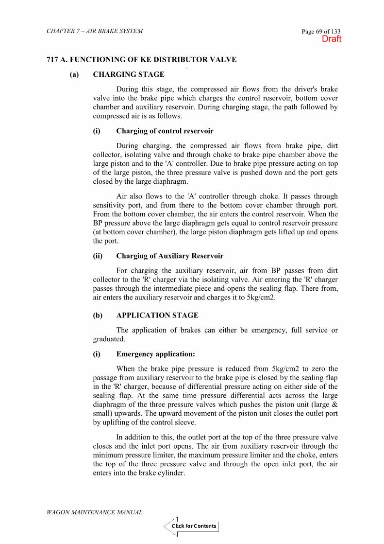
CHAPTER 7 – AIR BRAKE SYSTEM
WAGON MAINTENANCE MANUAL
Page 69 of 133
717 A. FUNCTIONING OF KE DISTRIBUTOR VALVE
. (a) CHARGING STAGE
During this stage, the compressed air flows from the driver's brake valve into the brake pipe which charges the control reservoir, bottom cover chamber and auxiliary reservoir. During charging stage, the path followed by compressed air is as follows.
(i) Charging of control reservoir During charging, the compressed air flows from brake pipe, dirt collector, isolating valve and through choke to brake pipe chamber above the large piston and to the 'A' controller. Due to brake pipe pressure acting on top of the large piston, the three pressure valve is pushed down and the port gets closed by the large diaphragm. Air also flows to the 'A' controller through choke. It passes through sensitivity port, and from there to the bottom cover chamber through port. From the bottom cover chamber, the air enters the control reservoir. When the BP pressure above the large diaphragm gets equal to control reservoir pressure (at bottom cover chamber), the large piston diaphragm gets lifted up and opens the port.
(ii) Charging of Auxiliary Reservoir For charging the auxiliary reservoir, air from BP passes from dirt collector to the 'R' charger via the isolating valve. Air entering the 'R' charger passes through the intermediate piece and opens the sealing flap. There from, air enters the auxiliary reservoir and charges it to 5kg/cm2.
(b) APPLICATION STAGE
The application of brakes can either be emergency, full service or graduated. (i) Emergency application:
When the brake pipe pressure is reduced from 5kg/cm2 to zero the passage from auxiliary reservoir to the brake pipe is closed by the sealing flap in the 'R' charger, because of differential pressure acting on either side of the sealing flap. At the same time pressure differential acts across the large diaphragm of the three pressure valves which pushes the piston unit (large & small) upwards. The upward movement of the piston unit closes the outlet port by uplifting of the control sleeve. In addition to this, the outlet port at the top of the three pressure valve closes and the inlet port opens. The air from auxiliary reservoir through the minimum pressure limiter, the maximum pressure limiter and the choke, enters the top of the three pressure valve and through the open inlet port, the air enters into the brake cylinder.
Draft
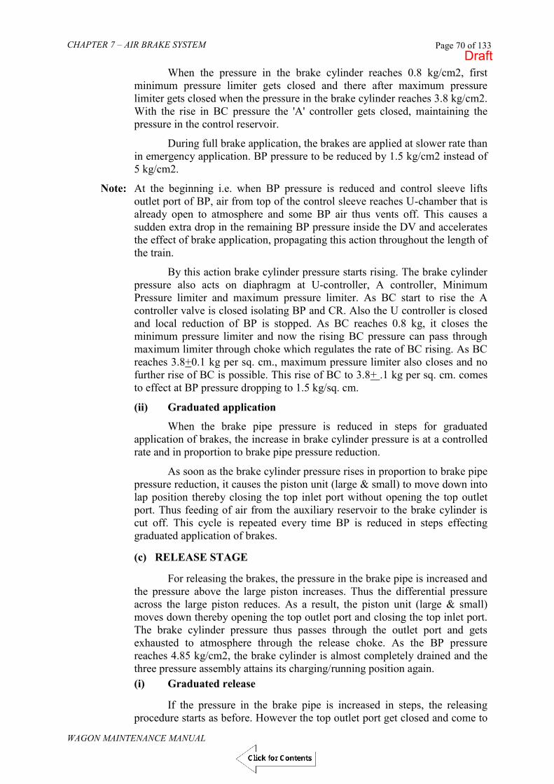
CHAPTER 7 – AIR BRAKE SYSTEM
WAGON MAINTENANCE MANUAL
Page 70 of 133
When the pressure in the brake cylinder reaches 0.8 kg/cm2, first minimum pressure limiter gets closed and there after maximum pressure limiter gets closed when the pressure in the brake cylinder reaches 3.8 kg/cm2. With the rise in BC pressure the 'A' controller gets closed, maintaining the pressure in the control reservoir.
During full brake application, the brakes are applied at slower rate than in emergency application. BP pressure to be reduced by 1.5 kg/cm2 instead of 5 kg/cm2.
Note: At the beginning i.e. when BP pressure is reduced and control sleeve lifts outlet port of BP, air from top of the control sleeve reaches U-chamber that is already open to atmosphere and some BP air thus vents off. This causes a sudden extra drop in the remaining BP pressure inside the DV and accelerates the effect of brake application, propagating this action throughout the length of the train.
By this action brake cylinder pressure starts rising. The brake cylinder pressure also acts on diaphragm at U-controller, A controller, Minimum Pressure limiter and maximum pressure limiter. As BC start to rise the A controller valve is closed isolating BP and CR. Also the U controller is closed and local reduction of BP is stopped. As BC reaches 0.8 kg, it closes the minimum pressure limiter and now the rising BC pressure can pass through maximum limiter through choke which regulates the rate of BC rising. As BC reaches 3.8+0.1 kg per sq. cm., maximum pressure limiter also closes and no further rise of BC is possible. This rise of BC to 3.8+ .1 kg per sq. cm. comes to effect at BP pressure dropping to 1.5 kg/sq. cm.
(ii) Graduated application
When the brake pipe pressure is reduced in steps for graduated application of brakes, the increase in brake cylinder pressure is at a controlled rate and in proportion to brake pipe pressure reduction.
As soon as the brake cylinder pressure rises in proportion to brake pipe pressure reduction, it causes the piston unit (large & small) to move down into lap position thereby closing the top inlet port without opening the top outlet port. Thus feeding of air from the auxiliary reservoir to the brake cylinder is cut off. This cycle is repeated every time BP is reduced in steps effecting graduated application of brakes.
(c) RELEASE STAGE
For releasing the brakes, the pressure in the brake pipe is increased and
the pressure above the large piston increases. Thus the differential pressure across the large piston reduces. As a result, the piston unit (large & small) moves down thereby opening the top outlet port and closing the top inlet port. The brake cylinder pressure thus passes through the outlet port and gets exhausted to atmosphere through the release choke. As the BP pressure reaches 4.85 kg/cm2, the brake cylinder is almost completely drained and the three pressure assembly attains its charging/running position again.
(i) Graduated release
If the pressure in the brake pipe is increased in steps, the releasing procedure starts as before. However the top outlet port get closed and come to
Draft

CHAPTER 7 – AIR BRAKE SYSTEM
WAGON MAINTENANCE MANUAL
Page 71 of 133
lap position as soon as piston unit (large & small) moves up due to fall of brake cylinder pressure.
ii) Manual Release
Sometimes manual release of brakes is very helpful and thus provision is made in the distributor valve for manually releasing the brakes. When a short pull is given to pulling lever, it tilts the pressure piece. As a result, the pressure rod and pin are pushed upwards against force of spring. The air thus flows from control reservoir and passes through port and then from narrow passage to atmosphere. This will continue until the brake pipe pressure acting on large piston moves the supporting plate down. This results in downward movement of the pin thereby closing the passage of air to exhaust. If however, there is no more pressure in brake pipe (i.e. after emergency application), when short pull is given to release handle then pressure piece is tilted & pin remains in top position. As a result control reservoir pressure is completely exhausted. The tilted pressure piece is then immediately restored to its initial position by spring. The brake cylinder pressure starts exhausting after control reservoir is exhausted upto 1.2 kg/cm2. and then simultaneously both get exhausted completely. During refilling, the pressure in brake pipe rises more rapidly via choke and port so that the large piston immediately moves down causing the pin to move to lap position.
717 C. SPECIFICATION OF KE DISTRIBUTOR VALVE
KE distributor valve is a graduated release type of valve and has been approved by UIC to comply with requirement of its specification no. 540 and 547.
718. TESTING OF KE TYPE DISTRIBUTOR VALVE
Schematic diagram of the test bench for KE valve is shown in Fig. 7.32. Test bench consists of the following components:-
(i). Source of compressed air supply at 7.5 Kg/cm2. (ii). Pressure regulator (Item no. 4) : to supply air at 6.5 Kg/cm2. (iii). Pressure regulator (Item no. 24): to supply air at 6 Kg/cm2. (iv). Brake cylinders (Item no. 17) : two numbers (v). Auxiliary reservoir [Item no 21(A) and 21(B)] each having capacity to store
100 liters of air at 6 Kg/cm2. (vi). Brake pipe reservoir (item no. 9) having capacity to store 60 liters of air at 6
Kg/cm2.
(vii). Equalizer reservoir (Item no. 7) to store air at 6 Kg/cm2 pressure. This reservoir supplies air to drivers brake valve whenever it is needed by DBV due to loss of air.
(viii). Drivers brake valve (item no. 6). It is same as provided in the locomotive. Its purpose is to control the brake pipe pressure.
(ix). Item no. 2 : Filter in supply to filter out any oil, grease etc.
(x). Item no. 22 : Auxiliary reservoir check valve. This prevents back flow of air
Draft

CHAPTER 7 – AIR BRAKE SYSTEM
WAGON MAINTENANCE MANUAL
Page 72 of 133
i.e. flow of air from auxiliary reservoir to supply.
(xi). Item no. 5 : Main reservoir to store 60, liters of air at 6.5 Kg/cm2.
(xii). Item no. 14 : Common pipe bracket, KE type distributor valve which is under test is to be mounted on this.
(xiii). Five pressure gauges to indicate the pressure in different locations as given below –
Item no. 25 : Main reservoir pressure. Item no. 26 : Brake pipe pressure Item no. 27 : Control reservoir pressure Item no. 28 : Auxiliary reservoir pressure
Item no. 29 : Brake cylinder pressure.
(xiv). Isolating cocks as given below-
Item no. 1: Supply of compressed air to main reservoir. Item no. 3 : For exhausting main reservoir pressure. Item no. 8 : For controlling air pressure in brake pipe with the help of
drivers brake valve. Item no. 10 : For isolating common pipe bracket from the brake pipe
reservoir. Item no. 11 : For exhausting brake pipe pressure. Item no. 12 : It is with a choke for releasing brake pipe pressure at a
desired rate for insensitivity test. Item no. 13 : It is with a choke for releasing brake pipe pressure for
sensitivity test. Item no. 15 : Provided between brake pipe line and control reservoir.
Normally it is kept closed and is used only for quick charging (or direct charging) of the control reservoir.
Item no. 16 : Isolating cock with a choke for exhausting brake cylinder pressure at a desired rate.
Item no. 19 : For isolating auxiliary reservoir from common pipe bracket.
Item no. 20 : Provided between brake pipe and auxiliary reservoir for direct charging of brake pipe (I.e. by bypassing the driver‟s brake valve).
Item no. 23 : It is the cock which connects the auxiliary reservoir with feed pipe in twin pipe system. This valve is kept closed in single pipe operation.
Item no. 30 : For exhausting auxiliary reservoir.
Draft

CHAPTER 7 – AIR BRAKE SYSTEM
WAGON MAINTENANCE MANUAL
Page 73 of 133
Fig. 7.32 TEST BENCH FOR KE DISTRIBUTOR VALVE
Draft

CHAPTER 7 – AIR BRAKE SYSTEM
WAGON MAINTENANCE MANUAL
Page 74 of 133
719. TEST REPORT PROFORMA FOR C3W/KE DISTRIBUTOR VALVE Type of Valve ………… Sr. No. ………… Sr. No.
Description of Test Observation
1. AR Charging Time from 0 to 4.8 Kg/ cm2 (Main Reservoir pressure > 7.5 Kg/ cm2)
2. CR Charging Time from 0 to 4.8 Kg/cm2 (Main Reservoir pressure >7.5 Kg/cm2)
3. Leakage Test (Brake Release) Check DV Leakage by Soap water only at joints.
FULL SERVICE APPLICATION & RELEASE
3.1 Brake Cylinder filling time from 0 to 3.6 Kg/cm2
18 to 30 seconds ±0.1
3.2 Maximum Brake Cylinder Pressure 3.8 Kg/cm2 3.3 Leakage Test (Application) Check
Leakage in DV by Soap water only at joints
3.4 Brake Cylinder Release Time from Max.B.C. Pressure i.e. from 3.8 +/-0.1 Kg/cm2 to 0.4 Kg/cm2
45 to 60 Seconds
4.1 OVERCHARGE PROTECTION (BP pressure 6 Kg/cm2)
CR pressure should not increase by more than 0.1 Kg/cm2 in 25 sec.
5.1 CR overcharge reduction test Overcharge CR to 5.7 Kg/cm2 and pull double release lever for 3 seconds.
Overcharged CR should come to regime pressure of 5 Kg/cm2.
EMERGENCY APPLICATION Single pipe 6.1 Brake Cylinder filling Time from 0 to 3.6
Kg/cm2 18 to 30 Seconds
6.2 Maximum Brake Cylinder Pressure 3.8 ± 0.1 Kg/cm2 6.3 Leakage Test (Emergency)
Check Leakage in DV by Soap water only at joints
No Leakage
6.4 Brake Cylinder Release Time from Max. B. C. Pressure i.e. from 3.8 ± 0.1 Kg/cm2 to 0.4 Kg/cm2
45 to 60 Seconds
SENSITIVITY & INSENSITIVITY 7.1 BP pressure drop at the rate of 0.6
Kg/cm2 in 6 Seconds Brake should start applying within 1 Sec.
8.1 With a pressure drop stopped immediately after the operation of Quick Service Valve
Brakes must remain applied.
Draft

CHAPTER 7 – AIR BRAKE SYSTEM
WAGON MAINTENANCE MANUAL
Page 75 of 133
Sr. No.
Description of Test Observation
9.1 BP pressures drop of 0.3 Kg/cm2 maximum in 60 seconds.
Brakes must not apply.
REFEEDING 10.1 Create leak in BC through a 2 mm choke BC pressure should
decrease initially but re-feeding should be available and BC pressure should get stabilized at some pressure.
11.1 GRADUATED APPLICATION Decrease BP pressure in steps as below - BP Pressure (Kg/cm2) 4.8 4.6 4.4 4.2 4.0 3.8 3.6
11.2 Continue Graduated Application until max. BC Pressure is obtained
BP pressure drop must be between 1.4 and 1.6 Kg/cm2
11.3 BP Pressure at maximum brake application
BP pressure drop must be between 3.4 & 3.7 Kg/cm2
12.1 GRADUATED RELEASE Increase BP pressure in steps as below – BP Pressure (Kg/cm2) 3.6 3.8 4.0 4.2 4.4 4.6 4.8
BC Pressure
12.2 Check BP Pressure when BC pressure is 0.4 Kg/cm2 (Recharging pressure to release BC Fully)
4.85 Kg/cm2 approx.
13.1 QUICK RELEASE TEST Apply emergency brake & pull briefly the double release valve lever
Brake cylinder & CR are automatically exhausted to zero
14.1 CR check valve reset test. Start recharging of the system
Control reservoir should be isolated from atmosphere when brake pipe pressure exceeds 0.2 Kg/cm2.
Draft

CHAPTER 7 – AIR BRAKE SYSTEM
WAGON MAINTENANCE MANUAL
Page 76 of 133
720. SINGLE WAGON TEST
„Single wagon Test‟ is performed on a wagon to ensure proper functioning of the air brake system. It is generally performed on the sick wagon attended in the sick line or whenever a subassembly of the air brake system is replaced either in depot or workshop. Single wagon test is also carried out after POH and after every change of distributor valve in the workshop. The different tests to be performed on the subassemblies of a wagon are as follows:
Test1: Leakage Test. Test2: Sensitivity and Insensitivity Test. Test3: Brake Application and Release Test. Test4: Graduated Application and Release Test. Test5: Check and adjust Slack Adjuster.
A. TOOLS AND EQUIPMENT
1. Test Rig 2. Spanners 10mm, 12mm
B. CONCEPT
Single Wagon Test is performed, by using a portable device called „Test Rig‟. This test rig provides all facilities similar to a driver‟s brake valve. The source of compressed air for conducting the test is through a compressor installed in depots and workshops for conducting various tests without the need of a locomotive. The part description and specification are given in table below.
C. PROCEDURE FOR SINGLE WAGON TESTING
A systematic lay-out of Single Wagon Test Rig (SWTR) is shown in fig. 7.33. This SWTR is utilised for testing the air brake system fitted on single wagon. The wagon should not be connected with the locomotive at the time of testing. The following procedure shall be followed for testing.
i. The wagon under testing is to be coupled at one end with the SWTR coupling
head BP and the other end should be closed with dummy coupling head. Pressure gauge should be fitted on brake cylinder.
ii. Couple the SWTR to the main line of compressor. iii. Place the isolating cock of distributor valve on the wagon in open position i.e.
the handle should be vertically down wards. iv. Set the pressure reducing valve (1) to 5 + 0.1 Kg/cm2 Open the cocks (2) and
(8) and so the angle cocks on the both ends of the wagons. Move the driver‟s brake valve (3) in the charging and release position.
v. Wait for about 5 minutes to charge the complete system. vi. Check the pressure in BP pressure gauge (7). Pressure should be 5+ 0.1
Kg./cm2 in BP. If there is pressure drop in the gauge (7) detect the source of leakage and eliminate it.
vii. Close cocks (2) & (8). Check the leakage on BP for one minute. viii. Open cock (2). Bring Driver‟s brake valve in full service application position.
Draft

CHAPTER 7 – AIR BRAKE SYSTEM
WAGON MAINTENANCE MANUAL
Page 77 of 133
ix. Record the brake cylinder filling time from 0 to 3.6 Kg./cm2 in brake cylinder pressure gauge.
x. Record maximum pressure in brake cylinder. xi. Record the pressure drop in BP from pressure gauge (4). xii. Record the piston stroke of brake cylinder. xiii. Bring Driver‟s brake valve in the charging and release position. xiv. Record the brake cylinder draining time from 3.8 + 0.1 to 0.4 Kg./cm2 in
brake cylinder pressure gauge & check complete release of brakes i.e. piston should reach its initial position.
xv. Open cock (8) for charging the reservoirs to 5 Kg./cm2 and close cock (2). xvi. Open cock (6) for checking sensitivity of brakes. Record time within which
brakes get applied. xvii. Close cock (6) and open cock (2). Wait till brakes are released. xviii. Close cock (2) and open cock (7) for checking the insensitivity of brakes. The
brakes should not apply. xix. Close cock (7) and (8) and open cock(2), BP pressure should rise to 5 Kg./cm2 xx. Close cock (2) and open cock (5) for emergency application. xxi. Record the brake cylinder charging time from 0 to 3.6 Kg./cm2 in BC pressure
gauge. xxii. Record maximum BC pressure. xxiii. Check the leakage in BC for 5 minutes. xxiv. Pull the manual release lever of distributor valve for about 10 sec. Brake
cylinder pressure should become zero automatically. xxv. The above tests should be done in both empty and loaded condition. xxvi. The results of test shall be recorded in the test proforma attached herewith.
D. PROFORMA FOR SINGLE WAGON TEST FOR WAGONS OTHER
THAN BOBR & BOBRN
S.No. Check Specified 1.
Pressure in BP
5 + 0.1 Kg./cm2
2. Pressure in AR 5 + 0.1 Kg./cm2 3. Leakage from the system after charging 0.1 kg/cm2 in one minute 4. 4.1
Full service application Brake cylinder filling time (Pressure rise from 0 to 3.6 kg/cm2) a) Empty b) Loaded
18 to 30 sec. 18 to 30 sec.
4.2 Maximum brake cylinder pressure a) Empty b) Loaded
3.8 + 0.1 kg/cm2 3.8 + 0.1 kg/cm2
4.3 Reduction in BP pressure required for full service application
1.3 to 1.6 kg/cm2
5. Release after full service application 5.1 Draining time (Brake cylinder pressure to fall
from 3.8 + 0.1 kg/cm2 to 0.4 kg/cm2 45 to 60 sec.
6. Sensitivity of brakes Isolate brake pipe from mainline. Check the response of brakes when the brake pipe pressure is reduced at the most equal to 0.6 kg/cm2 in 6 sec.
Brake should apply within 6 sec.
Draft
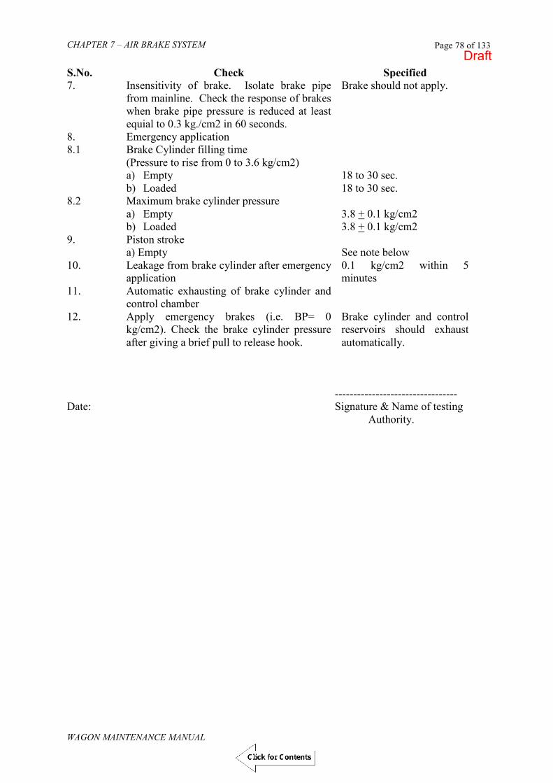
CHAPTER 7 – AIR BRAKE SYSTEM
WAGON MAINTENANCE MANUAL
Page 78 of 133
S.No. Check Specified 7. Insensitivity of brake. Isolate brake pipe
from mainline. Check the response of brakes when brake pipe pressure is reduced at least equial to 0.3 kg./cm2 in 60 seconds.
Brake should not apply.
8. Emergency application 8.1 Brake Cylinder filling time
(Pressure to rise from 0 to 3.6 kg/cm2) a) Empty b) Loaded
18 to 30 sec. 18 to 30 sec.
8.2 Maximum brake cylinder pressure a) Empty b) Loaded
3.8 + 0.1 kg/cm2 3.8 + 0.1 kg/cm2
9. Piston stroke a) Empty
See note below
10. Leakage from brake cylinder after emergency application
0.1 kg/cm2 within 5 minutes
11. Automatic exhausting of brake cylinder and control chamber
12. Apply emergency brakes (i.e. BP= 0 kg/cm2). Check the brake cylinder pressure after giving a brief pull to release hook.
Brake cylinder and control reservoirs should exhaust automatically.
--------------------------------- Date: Signature & Name of testing
Authority.
Draft

CHAPTER 7 – AIR BRAKE SYSTEM
WAGON MAINTENANCE MANUAL
Page 79 of 133
Fig. Ref. No. Description Qty. 1. Pressure reducing valve 1 2. Isolating cock 15 mm 1 3. Drivers brake valve 1 4. Pressure Gauge for BP 1 5. Isolating Cock 15 mm 1 6. Isolating Cock 15 mm with choke 1 7. Isolating Cock 15 mm with choke 1 8. Isolating cock 15 mm 1 9. Air Reservoir 40 L 1 10. Flexible hose BP 1 M long 1 11. Check valve 15 mm 1 12. Isolating cock 15mm 1 13. Adapter for AR 1 14. Adapter for CR 1 15. Adapter for BC 1 16. Flexible Hose 10mmx2 m long 3 17. Pressure gauge 3 18. Trolley (Not Shown) 1
Draft

CHAPTER 7 – AIR BRAKE SYSTEM
WAGON MAINTENANCE MANUAL
Page 80 of 133
Fig. 7.33 SINGLE WAGON TEST RIG (SWTR)
721. RAKE TEST
A schematic layout of rake test rig (RTR) is shown in Fig. 7.34. A rake consisting of 56 wagons can be tested with this rig. This rig may be used for testing the train in yard before attaching the engine.
The rake test rig has air supply and mobile test rig. The mobile test rig is
having a cubical structure and is mounted on wheels. It can be taken to the yards and sick lines. The procedure is as follows:
A. Carry out Visual Examination. B. Prepare set up (Rig) for Rake Test. C. Conduct Leakage, Service Application and Release Test.
Visual inspection is a check of air brake subassembly, for any damage on the brake pipe, hose coupling etc and then rectifying it. The steps are :-
i) Inspect loose suspension brackets and anti-pilferage devices of all air brake
subassemblies ii) Visually inspect for any problem/damage in the brake pipe, hose pipe, coupling
etc. iii) Rectify or replace the problematic part/subassembly. Rake Test can be performed, by using a portable device called „Test Rig‟ (Fig. 7.32 B) or by locomotive. The test rig provides all facilities like a locomotive to
Draft
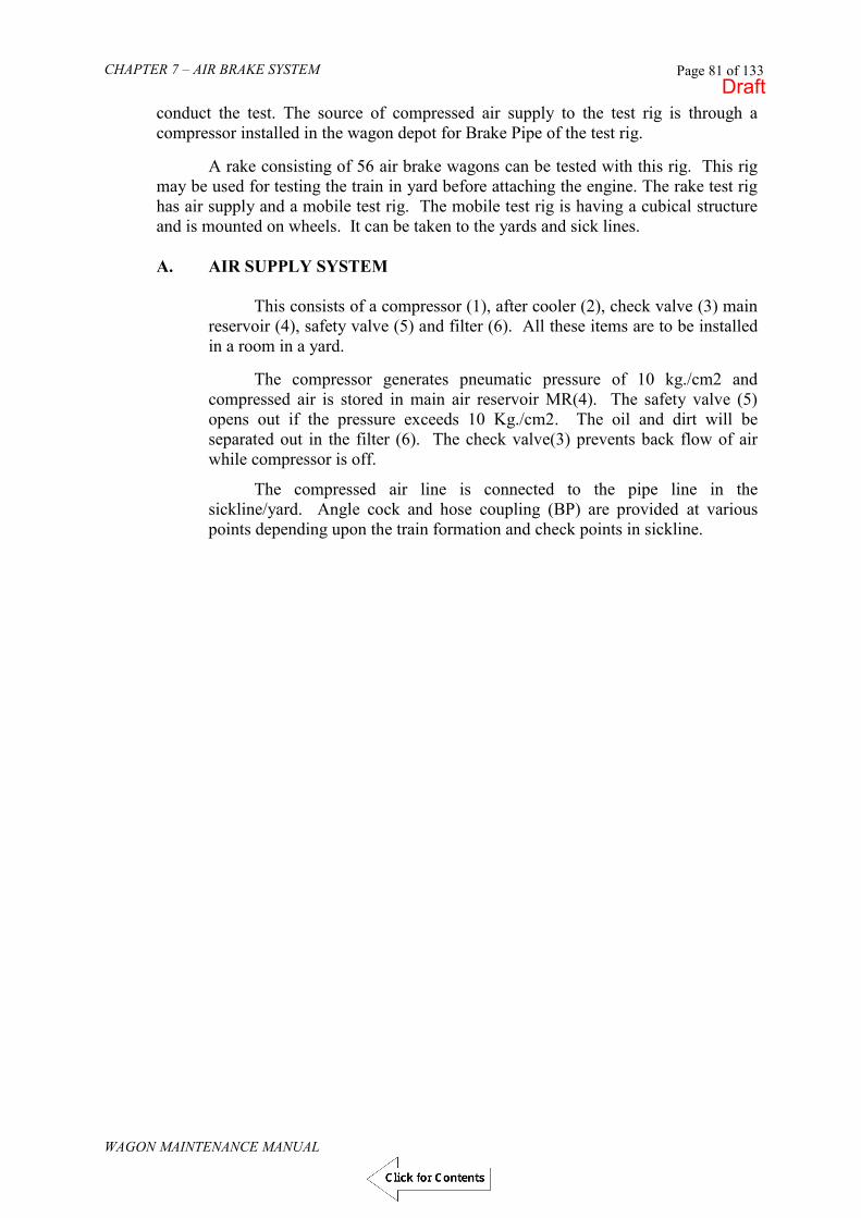
CHAPTER 7 – AIR BRAKE SYSTEM
WAGON MAINTENANCE MANUAL
Page 81 of 133
conduct the test. The source of compressed air supply to the test rig is through a compressor installed in the wagon depot for Brake Pipe of the test rig.
A rake consisting of 56 air brake wagons can be tested with this rig. This rig
may be used for testing the train in yard before attaching the engine. The rake test rig has air supply and a mobile test rig. The mobile test rig is having a cubical structure and is mounted on wheels. It can be taken to the yards and sick lines.
A. AIR SUPPLY SYSTEM
This consists of a compressor (1), after cooler (2), check valve (3) main
reservoir (4), safety valve (5) and filter (6). All these items are to be installed in a room in a yard.
The compressor generates pneumatic pressure of 10 kg./cm2 and
compressed air is stored in main air reservoir MR(4). The safety valve (5) opens out if the pressure exceeds 10 Kg./cm2. The oil and dirt will be separated out in the filter (6). The check valve(3) prevents back flow of air while compressor is off.
The compressed air line is connected to the pipe line in the sickline/yard. Angle cock and hose coupling (BP) are provided at various points depending upon the train formation and check points in sickline.
Draft

CHAPTER 7 – AIR BRAKE SYSTEM
WAGON MAINTENANCE MANUAL
Page 82 of 133
SICK/PIT LINE 10 MM FLEXIBLE 9 PIPE 10
5 13 8 12a 32NB 7 7 6 8 8 1 2
32 NB 11
9
32NB BRAKE PIPE
Fig. Ref. No. Description Qty. 1. Compressor 2000L/Min pressure 8-10 Kg/Cm2 1 2. After Cooler 1 3. Check valve 1 4. Main reservoir 300 lts.1 1 5. safety vlave 1 6. Filter 1 7. Cut off angle cock 2 8. Brake hose coupling BP 4 9. Pressure gauge 2 10. Driver‟s Brake valve 1 11. Relay valve 1 12. Isolating cock a,b,c,d 4 13. 10 mm FLEXIBLE HOSE 1
Fig. 7.34 RAKE TEST RIG
12b
12c
3 4
12d
Draft

CHAPTER 7 – AIR BRAKE SYSTEM
WAGON MAINTENANCE MANUAL
Page 83 of 133
B. MOBILE TEST RIG
The rig consists of brake hose coupling BP (8) and isolating cock (12) at the inlet of the mobile test rig. The air connection can be tapped from one of the points of sickline. The mobile test rig is provided with driver‟s brake valve (10).
Brake pipe in the rake is charged while driver‟s brake valve (10) is
kept in released and running position. The driver‟s brake valve inlet is connected to MR. It regulates the pressure to 5 kg./cm2 through the relay valve (11). Isolating cock (12d) is provided to isolate BP from driver‟s brake valve (10).
The relay valve (11) has been provided in the system for augmenting
the feeding capacity of driver‟s brake valve. The hose coupling of BP is connected to the brake pipe coupling of the rake.
Note : In case rake test rig is not available, testing may be done by engine.
C. TOOLS AND EQUIPMENT
1. Rake Test Rig/Locomotive. 2. Open End spanner 18x19” 3. Spanner 10mm, 12mm
D. PROCEDURE FOR RAKE TESTING
Attach the rake test rig to the rake through the couplings. Carry out tests as per the procedure given in G-97 Annexure-XI (Latest amendment).
722. REPAIR AND MAINTENANCE IN SICKLINE
i. Check for any missing component and replace them, wherever necessary. ii. Charge the BP pressure and check for leakage iii. Check whether the application and release of brakes is taking place properly.
Also check for the free movement of brake rigging. iv. Drain the brake pipe, control reservoir and auxiliary reservoir fully and ensure
that there is no pressure in the system. v. Remove the drain plug of auxiliary reservoir, control reservoir and centrifugal
dirt collector and allow the draining of the condensate. Then charge the brake pipe and allow air to come out to the plug holes for some time so that all the dirt and other impurities may be driven out.
vi. Remove filter housing of the common pipe bracket, clean the filter and refit
making replacements, if necessary.
vii. Remove the brake cylinder breather hole strainer, clean it and refit making replacements, wherever necessary.
viii. Check the handles of the cut off angle cock and isolating cock are moving
freely. If there is any resistance, open the assembly, overhaul it, reassemble and ensure that there is free movement.
Draft
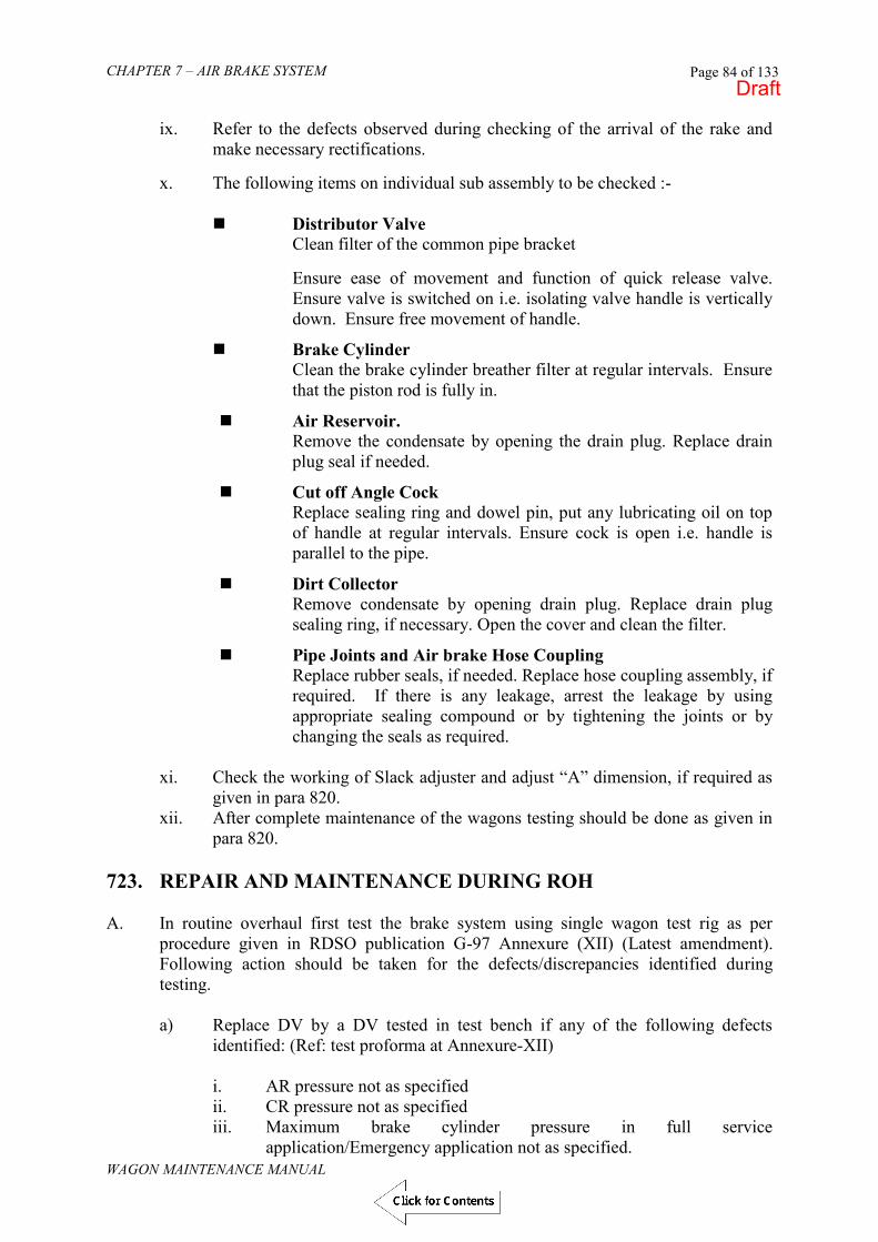
CHAPTER 7 – AIR BRAKE SYSTEM
WAGON MAINTENANCE MANUAL
Page 84 of 133
ix. Refer to the defects observed during checking of the arrival of the rake and
make necessary rectifications. x. The following items on individual sub assembly to be checked :-
Distributor Valve
Clean filter of the common pipe bracket Ensure ease of movement and function of quick release valve. Ensure valve is switched on i.e. isolating valve handle is vertically down. Ensure free movement of handle.
Brake Cylinder Clean the brake cylinder breather filter at regular intervals. Ensure that the piston rod is fully in.
Air Reservoir. Remove the condensate by opening the drain plug. Replace drain plug seal if needed.
Cut off Angle Cock Replace sealing ring and dowel pin, put any lubricating oil on top of handle at regular intervals. Ensure cock is open i.e. handle is parallel to the pipe.
Dirt Collector Remove condensate by opening drain plug. Replace drain plug sealing ring, if necessary. Open the cover and clean the filter.
Pipe Joints and Air brake Hose Coupling Replace rubber seals, if needed. Replace hose coupling assembly, if required. If there is any leakage, arrest the leakage by using appropriate sealing compound or by tightening the joints or by changing the seals as required.
xi. Check the working of Slack adjuster and adjust “A” dimension, if required as given in para 820.
xii. After complete maintenance of the wagons testing should be done as given in para 820.
723. REPAIR AND MAINTENANCE DURING ROH A. In routine overhaul first test the brake system using single wagon test rig as per
procedure given in RDSO publication G-97 Annexure (XII) (Latest amendment). Following action should be taken for the defects/discrepancies identified during testing.
a) Replace DV by a DV tested in test bench if any of the following defects
identified: (Ref: test proforma at Annexure-XII)
i. AR pressure not as specified ii. CR pressure not as specified iii. Maximum brake cylinder pressure in full service
application/Emergency application not as specified.
Draft

CHAPTER 7 – AIR BRAKE SYSTEM
WAGON MAINTENANCE MANUAL
Page 85 of 133
iv. Brake cylinder filling time/draining time after full service and/or emergency application not as specified.
v. Insensitivity/sensitivity parameters are not as specified. vi. Leakage through distributor valve. vii. Brake cylinder pressures in empty & loaded condition are not within
the specified limit. b) Replace brake cylinder by tested brake cylinder, if following defects are
identified.
i. Leakage from brake cylinder after emergency application is not as specified.
ii. If any visual damage is noticed.
c) Examine and repair or replace Seals/Gaskets of pipe and joint fittings if leakage rate of system is not within specified limits.
i) Replace the angle cock if it is leaking or damaged ii) Replace leaking Guard‟s Emergency Brake Valve, isolating cock,
and quick coupling of brake van. iii) Examine rigging/Slack Adjuster if Piston Stroke is not as
specified. (See Annexure - XV & XVI of G-97) B. Carry out following checks and examinations. a) Cut off Angle Cock
Check for easy operation of cut-off angle cock. If found jammed put a few drops of light lubricating oil on top of the cock and give light hammer shocks on the top of the cock simultaneously trying to operate the handle. Operate handle 10-12 times to ensure smooth movement. If working of angle cock even after lubrication is not smooth replace by tested angle cock.
b) Dirt Collector
Open the drain plug and drain out the Condensate and replace the drain plug. If the leather washer is found defective it should be changed.
c) Brake Cylinder Check the brake cylinder for smooth movement of piston. Lubricate the piston
by injecting 2 cc of lubricating grease through the gauge point. Brake cylinder movement even after lubrication is not smooth, replace by tested brake cylinder.
d) Auxiliary Reservoir/Control Reservoir Open the drain plug and drain out the condensate and replace the drain plug.
If the Leather Washer is found defective it should be changed.
e) Hose Coupling i. Check serviceability of hose coupling. ii. Check the Gasket for any visual damage and replace if found
necessary.
Draft

CHAPTER 7 – AIR BRAKE SYSTEM
WAGON MAINTENANCE MANUAL
Page 86 of 133
f) Guard‟s Emergency Brake Valve Check easy operation of Valve. Operate 5 to 6 times. Defective valve should be replaced.
g) Isolating Cock for BVZC Brake Vans
Check easy operation of cock. Operate 5 to 6 times. Replace defective isolating cock.
h) Quick Coupling for BVZC Brake Vans
Check for proper working and replace if defective. i) Load Sensing Device (Fig. 4, 5, 7, 23 & 24 of G-97) for BOBR/BOBRN
Wagons Check that wagons fitted with C3W2 ORKEO DV are provided with single piece as per RDSO drawing No. WD- 01065 – S- 01 LSD type.
i. Check proper working of single piece load sensing device fitted on bogie. For checking the proper working of LSD in loaded condition press the piston of operating valve by inserting a bar.
C. Ensure the following :-
i. Hose coupling support at both ends are fitted properly. ii. All mounting nuts and bolts of various equipment, pipe fitting and pipe
joints are secured and tight in position.
iii. APD of the following are as per RDSO drawings and specifications.
(a) Angle cock iv) Examine and ensure that the Air Brake equipment are not physically,
damaged from outside. D. After carrying out all the work, test the brake system in single wagon test rig for all
parameters as per procedure given in Annexure XII of G-97. Rectify the defects if identified during testing. In no case wagon with brake system not meeting requirement be allowed to come out from ROH repair.
E. Attend to special modifications, as ordered from time to time in the nominated
Depots. F. Touch up paint and lettering where necessary. G. Details of replacement of DV shall be marked on the sole bar as indicated in RDSO
Drg. No. WD - 93003 - S - 01.
H. Defective equipment replaced should be taken to test bench for repair and after repair use them as spare unit for further ROH of wagons.
a) For the repair of Air Brake Equipment necessary spares shall be spare parts procured from approved Air Brake Supplier shall be readily available with the Depot. A maintenance kit for different equipment is given at Annexure
Draft

CHAPTER 7 – AIR BRAKE SYSTEM
WAGON MAINTENANCE MANUAL
Page 87 of 133
XII of G-97. The Depot shall make assessment of the total quantity required and procure the same in Kit form. Small quantity of spares, which are not covered in maintenance kit may also be require. Such spares can be purchased as non stock item or by cash imprest.
b) Only used for repairs. Under no circumstances Shop made/duplicate spares shall be used. The marking on items shall be seen to verify the Supplier.
c) ROH Maintenance Depot should have sufficient Nos. of various spare assemblies for unit exchange.
d) ROH Maintenance Depot should have following Repair and Maintenance facilities for various assemblies :-
Facilities for opening, repair, assembly and testing of all type of DVS.
Facilities for Opening, Repair, Assembly and Testing of Angle cock, Dirt collector, Brake Cylinder, Isolating Cock, Guard‟s emergency brake valve isolating cock and quick coupling.
The maintenance facilities for repair of various assemblies should be similar for what has been recommended for POH.
e) Do not allow wagon to come out from ROH repair without APD & additional
APD of DV and APD of angle cock. f) After complete maintenance of the wagons testing should be done as given in
para 20. 724. PERIODICAL OVERHAUL OF AIR BRAKES SYSTEM The following procedure shall be followed for the POH of Air Brake Equipment
i. Remove APD of DV & Angle Cocks from wagon. ii. Remove all assembly i.e. DV, Brake cylinder, Angle cock, Auxiliary
Reservoir and Dirt Collector from Wagon. iii. Remove Guard‟s emergency brake valve, Isolating cock and quick
coupling also form brake van. iv. Remove automatic load changeover device also from wagon in case of
BOBR/BOBRN Wagons v. Remove pipe bracket, pipe clamps, pipe joints and strip all pipes. vi. The pipes should be slightly hammered to loosen the rust and scale. vii. After de-scaling, pipe must be blown with dry compressed air to ensure
complete cleaning of rust and scale. viii. Clean the outside of all pipes thoroughly. ix. Examine all pipes for damage, cut, corrosion, etc. Damaged and
heavily corroded pipe must be replaced. x. Examine joints for the following damage:
a) Sockets for cracks b) Fixed Flanges for straightness c) Sockets and flanges for Corrosion/damages & replace defective parts. xi. Replace all rubber items of pipe joints irrespective of conditions of old
items.
Draft

CHAPTER 7 – AIR BRAKE SYSTEM
WAGON MAINTENANCE MANUAL
Page 88 of 133
xii. Assemble pipe joints. Tight bolts properly and secure them by spring washer and nut.
xiii. Fit, properly overhauled and tested, following assembly.
a) DV. In case new DV is fitted it should be ensured that casting tag is available on DV.
b) Pipe bracket c) Dirt Collector d) Both Angle Cocks e) Brake Cylinder f) Auxiliary Reservoir g) Guard‟s emergency brake valve in case of BrakeVan. h) Isolating cock in case of Brake Van. i) Quick Coupling in case of Brake Van. j) Automatic empty load change over device in case of
BOBR/BOBRN Wagons.
Use new rubber items for joints between pipe and equipment irrespective of condition of old items.
xiv Properly secure nut and bolts of joints between pipe and equipment. xv Examine all pipe and pipe fittings and brackets and properly secure
them. Pipes should not be loose inside the pipe clamps. xvi Fit following APD :
a) APD of Angle Cock xvii Fit overhauled Hose Couplings at both ends of Brake Pipe.
xviii PAINTING
All items shall be painted black as per standard practice. xix. MARKING
Besides standard marking, details shown in Drg. No. WD-93003-S-01 shall also be stencilled on the sole bar.
xx. For overhauling of various assemblies removed from wagon, follow
the procedure given in various Annexures of RDSO publication No. G-97 (Latest amendment) as mentioned below :-
xxi. TESTING OF WAGON BRAKE EQUIPMENT
Single Wagon Test This test shall be conducted on the wagon with Single Wagon Test Rig. The procedure and the specified values are given at para 720.
If the values obtained are not within the specified limits, identify the defects and rectify the defects. Single Wagon Test shall be carried out once again after rectification.
Draft
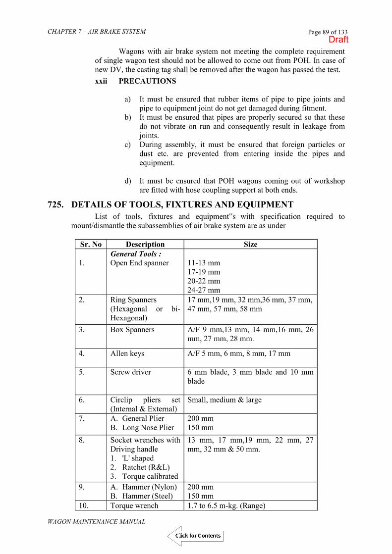
CHAPTER 7 – AIR BRAKE SYSTEM
WAGON MAINTENANCE MANUAL
Page 89 of 133
Wagons with air brake system not meeting the complete requirement of single wagon test should not be allowed to come out from POH. In case of new DV, the casting tag shall be removed after the wagon has passed the test.
xxii PRECAUTIONS
a) It must be ensured that rubber items of pipe to pipe joints and pipe to equipment joint do not get damaged during fitment.
b) It must be ensured that pipes are properly secured so that these do not vibrate on run and consequently result in leakage from joints.
c) During assembly, it must be ensured that foreign particles or dust etc. are prevented from entering inside the pipes and equipment.
d) It must be ensured that POH wagons coming out of workshop
are fitted with hose coupling support at both ends.
725. DETAILS OF TOOLS, FIXTURES AND EQUIPMENT
List of tools, fixtures and equipment‟s with specification required to mount/dismantle the subassemblies of air brake system are as under
Sr. No Description Size 1.
General Tools : Open End spanner
11-13 mm 17-19 mm 20-22 mm 24-27 mm
2. Ring Spanners (Hexagonal or bi-Hexagonal)
17 mm,19 mm, 32 mm,36 mm, 37 mm, 47 mm, 57 mm, 58 mm
3. Box Spanners A/F 9 mm,13 mm, 14 mm,16 mm, 26 mm, 27 mm, 28 mm.
4. Allen keys A/F 5 mm, 6 mm, 8 mm, 17 mm
5. Screw driver 6 mm blade, 3 mm blade and 10 mm blade
6. Circlip pliers set (Internal & External)
Small, medium & large
7. A. General Plier B. Long Nose Plier
200 mm 150 mm
8. Socket wrenches with Driving handle 1. 'L' shaped 2. Ratchet (R&L) 3. Torque calibrated
13 mm, 17 mm,19 mm, 22 mm, 27 mm, 32 mm & 50 mm.
9. A. Hammer (Nylon) B. Hammer (Steel)
200 mm 150 mm
10. Torque wrench 1.7 to 6.5 m-kg. (Range)
Draft

CHAPTER 7 – AIR BRAKE SYSTEM
WAGON MAINTENANCE MANUAL
Page 90 of 133
Special Tools: KE- Type 11. Diaphragm Tool 4A54802 12. Adjustment Tools 4A59318 13. Tools for Locking screw of bottom cover 3KB3349 14. Clamping fixture or DV holding fix 15. Wrench for Max. Limiter 4A47740 16. Installation Tools (Assembly punch) 4A93186 17. Thrust piece 18. Installation hook 19. Adjusting key 20. Guide Tool for pin (92)
Pressure rod (1A) sub assembly Special Tools: C3W –Type 21. SCT6014 Two-pin tool for part no. 74 22. SCT6016 Two-pin tool for part no. 72 23. RPBF 0003 Holding fixture for guide 76 24. Socket Spanner (SCT6092) 50 mm 25. Stem leading Tool (SCT6017) 26. Bent Tool (SCT6026) for removing air from diaphragm 27. "O" Ring positioning (SCT 6015) Tool
(b). DIRT COLLECTOR
Sr.No Description Size 1.
General tools : Single end spanner
A/F 27 mm
2. Socket spanner 19, 22, 24 mm 3. Double Ended spanner (17-19); (22-24) 4. DC- holding fixture or vice with semi-
circular jaws 125 mm
5. Screw driver 8 mm (Blade) (c). BRAKE CYLINDER
Sr.No. Description Size 1. Brake cylinder Assembly Fixture 2.
General Tools : Torque wrench
Torque of 200 cm-kg.
3. Socket wrench 19 mm 4. Ring spanner Bi-hex (19-24) 5. Screw driver 8 mm blade 6. Double Ended spanner A/F 13x14 mm, 32x36 mm
(d). AIR RESERVOIR
Sr.No. Description Size 1. Open end spanner A/F 28 mm A/F 22X24
(17-19) (22-24) 2. Socket spanner 19,22 mm, 24 3. Screw driver 8 mm Blade
Draft

CHAPTER 7 – AIR BRAKE SYSTEM
WAGON MAINTENANCE MANUAL
Page 91 of 133
(e). CUT OFF ANGLE COCK
Sr.No. Description Size 1. Open end spanner A/F 63 2. Double open end spanner (11-13), (17-19) 3. Screw driver 8 mm Blade
(f). SLACK ADJUSTER
Sr.No. Description Size 1. Double Ended Spanner (11-13) 2. Special spanner (E) 3. Circlip plier spring type ( C ) (External) 203.2 mm to 250 mm 4. Circlip plier bend nose type (Internal)(D) 250 mm to 304.8 mm 5.
Special Tools : Jacking Tool (B)
(g). HOSE COUPLING
Sr.No. Description Size 1. Pipe wrench 450 mm 2. Open end tool 55, 65
Draft

CHAPTER 7 – AIR BRAKE SYSTEM
WAGON MAINTENANCE MANUAL
Page 92 of 133
726. BRAKE POWER CALCULATIONS FOR BOXN WAGON
TYPE OF BRAKE SYSTEM = AIR BRAKE BRAKE CYLINDER DIA = 355 mm NO OF CYLINDERS = ONE TOTAL EFFECTIVE PISTON FORCE = 3600 Kg (K)AFTER SUBTRACTION OF RESTORING SPRING FORCE AT A STORKE OF 135mm LEVERAGE EMPTY = 335 x 12 =6.5
620 LOADED = 458 x 12 =11.05
497 TOTAL BRAKE BLOCK PRESSURE P=(K i - 12Q) RIGGING EFFICIENCY = 0.9 FORCE OF SLACK ADJUSTER SPRING Q= 200 Kg P Empty 18900 Kg P Loaded 33642 Kg BRAKE PERCENTAGE P x100 Tare or gross BRAKE PERCENTAGE EMPTY = 18900 x100 = 86.5 % 21800 BRAKE PERCENTAGE LOADED = 33642 x 100 = 41.4% 21800 BRAKE POWER AT CHANGE WEIGHT =18900 x100 = 45.5% P(TARE)100 42500 CHANGE WT P(GROSS)x 100 = 33642 x 100 =79.2% CHANGE WT 42500
Fig 8.35BRAKE POWER CALCULATIONS FOR BOXN WAGON
Empty Load Box
To Bogie
Slack adjuster
Gross 81.28t
41.4%
44.5%
79.2%
86.5%
42.5tChange Wt.
Tare 21.8t
3354 58
497
6 20
Brake Cylinder 355 mm 0
FIG. 7.35
Draft
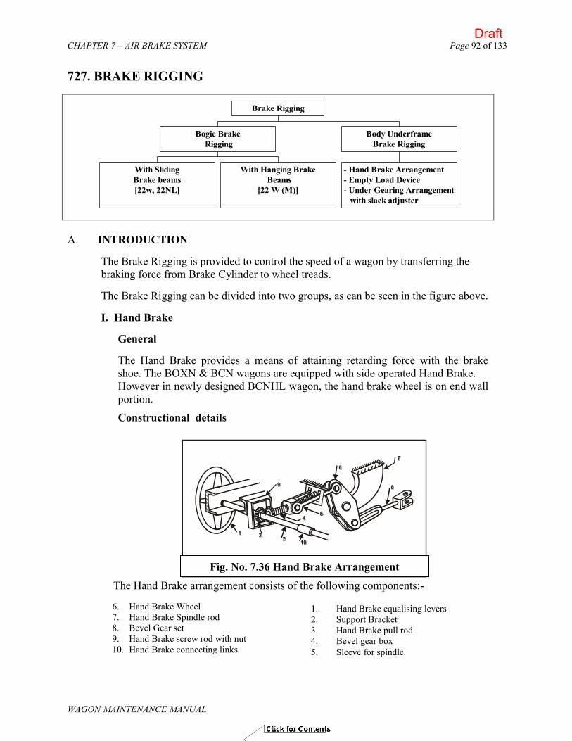
CHAPTER 7 – AIR BRAKE SYSTEM Page 92 of 133
WAGON MAINTENANCE MANUAL
727. BRAKE RIGGING
With SlidingBrake beams[22w, 22NL]
With Hanging Brake Beams
[22 W (M)]
Bogie Brake Rigging
- Hand Brake Arrangement- Empty Load Device- Under Gearing Arrangement with slack adjuster
Body UnderframeBrake Rigging
Brake Rigging
A. INTRODUCTION
The Brake Rigging is provided to control the speed of a wagon by transferring the braking force from Brake Cylinder to wheel treads.
The Brake Rigging can be divided into two groups, as can be seen in the figure above.
I. Hand Brake
General
The Hand Brake provides a means of attaining retarding force with the brake shoe. The BOXN & BCN wagons are equipped with side operated Hand Brake. However in newly designed BCNHL wagon, the hand brake wheel is on end wall portion.
Constructional details
Fig. No. 8.36 Hand Brake Arrangement
6. Hand Brake Wheel 7. Hand Brake Spindle rod 8. Bevel Gear set 9. Hand Brake screw rod with nut 10. Hand Brake connecting links
1. Hand Brake equalising levers 2. Support Bracket 3. Hand Brake pull rod 4. Bevel gear box 5. Sleeve for spindle.
The Hand Brake arrangement consists of the following components:-
Fig. No. 7.36 Hand Brake Arrangement
Draft
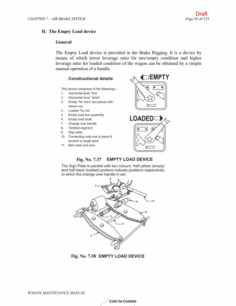
CHAPTER 7 – AIR BRAKE SYSTEM Page 93 of 133
WAGON MAINTENANCE MANUAL
II. The Empty Load device
General
The Empty Load device is provided in the Brake Rigging. It is a device by means of which lower leverage ratio for tare/empty condition and higher leverage ratio for loaded condition of the wagon can be obtained by a simple manual operation of a handle.
FIG. 8.37 EMPTY LOAD DEVICE
This device comprises of the followings :-1. Horizontal lever "live'2. Horizontal lever "dead'3. Empty Tie rod in two pieces with
sleeve nut4. Loaded Tie rod5. Empty load box assembly6. Empty load shaft7. Change over handle8. Toothed segment9. Sign plate10. Connecting rods-one is plane &
another is single twist11. Bell crank and pins
Constructional details EMPTY
LOADED
The Sign Plate is painted with two colours. Half yellow (empty) and half black (loaded) portions indicate positions respectively, to which the change over handle in set.
FIG. 8.38 EMPTY LOAD DEVICE
1
10
7
9 8
6 5
3
4
2
Fig. No. 7.37
Fig. No. 7.38
Draft

CHAPTER 7 – AIR BRAKE SYSTEM Page 94 of 133
WAGON MAINTENANCE MANUAL
III. Components
Depending on the brake beam arrangements, brake rigging can be of following two types.
Sliding Brake Beam
For CASNUB 22 W, 22-NL, NLB, NLM, HS, HS (Mod- I), HS (Mod- II) & NLC bogies, the brake beam is of sliding type, having fabricated box-steel structure with integral cast steel pieces for strut & brake-heads. Hanging Type Brake Beam:- For CASNUB 22W(M) bogie, hanging type cast steel brake beams are provided. Brake heads and blocks are secured by key and they are further assembled with brake beams through spring loaded brake shoe adjuster.
MAIN PULL ROD
EQUALISING LEVER
BRAKE BEAM
PUSH ROD
END PULL ROD
Fig 8.40
SIDE FRAMEHANGERBRACKET BRAKE HEAD
END PULL ROD
EQALISING LEVER
BRAKE BEAM
PUSH BEAM
HANGER
Hanging brake beam without additional brake beam support
Fig. No. 7.39
Fig. No. 7.40
Draft

CHAPTER 7 – AIR BRAKE SYSTEM Page 95 of 133
WAGON MAINTENANCE MANUAL
Body Underframe Components
Details of components and assemblies used in various types of brake rigging
arrangements are given below and shown in figure;
Fig. No. 8.42 Body Underframe
Fig 8.41
ADDITIONALBRAKE BEAM HANGER SUPENSION
BRACKET
11. End pull rod 12. Equalising lever 13. Push rod 14. Brake beam 15. Brake head assembly 16. Brake beam hanger 17. Brake block 18. Brake show key 19. Brake wear plate 20. Brake gear pins, washers,
cotters
1. Short pull rod 2. Long pull rod 3. Control rod with head 4. Horizontal lever 5. Empty tie rod with sleeve
nut 6. Loaded tie rod 7. Empty load device 8. Hand brake pull rod 9. Hand Brake arrangement 10. Slack Adjuster
Hanging brake beam with additional brake beam support.
Fig. No. 7.41
Fig. No. 7.42
Draft

CHAPTER 7 – AIR BRAKE SYSTEM
WAGON MAINTENANCE MANUAL
Page 96 of 133
BRAKE-HEAD REPLACEMENT
CASNUB-22NL, 22NLB, 22W, 22NLM, 22HS, 22HS (Mod-I), 22HS (Mod-II) & 22 NLC Brake Beams
CASNUM 22W (M) Brake beam:
a) Remove split pin and washer from brake beam ends. Remove pin securing brake shoe adjuster with brake beam by removing
b) Take the Brake Heads out of the Brake Beam along with Brake shoe adjuster c) Disengage brake shoe adjuster form brake head by removing bolt after disengaging
split pin, nut, cover, spring and adjusting piece. d) Assemble the new brake head with brake shoe adjuster. e) Secure brake heads on brake beam end by putting washer and split pin.
Fig. : 8.43
2. Worn out brake head to be gas cut
A-A
75
40
3. Brake beam end after gas cutting
1. Cross hatched portion to be gas cutA
A
a) Remove worn-out brake head. Other members, if damaged, should be built up by welding, followed by proper cleaning and finishing operation, as shown in figure to the right
4. Brake head for reclamation This can be made by modifying brake head of 22 W bk beam
5. Sectional view showing welding details
45
76
4 1
Fig. : 8.44
6. Reclaimed brake beam end CANSUB-22 NL / NLB / NLM / HS bogies
Modified new brake head
b) Weld new brake head at correct position.
Fig. No. 7.43 Fig. No. 7.44
Draft

CHAPTER 7 – AIR BRAKE SYSTEM
WAGON MAINTENANCE MANUAL
Page 97 of 133
Holes of end pull rod pins to be used for brake adjustment as per diameter of wheels.
Hole Wheel diameter on tread A Between 1000 & 982 B Between 981 & 963 C Between 962 & 944 D Between 943 & 925 E Between 924 & 906
The figure on next page shows where the holes are. The push rod is provided with two holes at either end. During service, in case of wear in
brake blocks, manual adjustment to outer hole may be done for maintaining brake power. THE PUSH ROD IS HAVING
728. COMPOSITION BRAKE BLOCK
Indian Railways using cast iron brake blocks for braking on freight stock. The frictional properties of cast iron brake blocks decline with the increase in speeds resulting in increased braking distance. The composition brake block has the following benefits as compared to cast iron brake blocks:-
i) Reduced braking distance due to uniform coefficient of friction. ii) Reduced weight. iii) Longer life due to reduced wear of composition brake blocks. iv) Reduced noise during braking.
Initially L—type composition brake blocks were developed and tried out. After
successful trials the decision was taken to progressively switch over to L- type composition brake blocks. Presently following firms are approved for regular supply of L- type composition brake blocks:-
FIG. : 8.45
A B C D E
Fig. No. 7.45
Draft

CHAPTER 7 – AIR BRAKE SYSTEM
WAGON MAINTENANCE MANUAL
Page 98 of 133
1. M/s Rane Brake Lining, Chennai. 2. M/s BIC Auto Pvt. Ltd. Faridabad. 3. M/s Escorts Ltd,. Faridabad. 4. M/s Allied Nippon 5. M/s Cemcon engineering Co. Pvt. Ltd Rohtak. 6. M/s Hindustan composites Ltd. Aurangabad. 7. M/s ILPL Mumbai 8. M/s Bony Polymers Ltd. Faridabad. 9. M/s Greysham (International) super friction Pvt. Paonta Sahib 10. M/s Sundram Brake lining Ltd. Chennai.
Cast iron brake blocks can be replaced by L- type composition brake blocks and
condemning limit is the same as that of CI.
K-type composition brake blocks having higher average coefficient of friction are being developed. Moreover adoption of K-type brake block requires change in brake rigging. Development of K-type brake blocks at testing stage at present. Presently following firm are approved for regular supply of L –Type composition brake block.
1. M/s Rane Brake lining, Chennai 2. M/s BIC Auto Pvt. Ltd. Faridabad 3. M/s Hindustan composites Ltd. Aurangabad 4. M/s ILPL Mumbai 5. M/s Greysham (International) super friction Pvt. Paonta Sahib
Do’s and Don’ts for fitment of Composition Brake Blocks
The following procedure shall be followed to ensure proper fitment of
composition brake blocks; To be done
i) Brake block shoe key shall be of spring steel as per RDSO drawing ii) Brake head shall be of spring steel as per RDSO drawing iii) Brake block taper should match with the wheel taper i.e. lower thickness of brake
block towards flange of wheel disc and higher thickness towards other side of wheel flange
iv) Sufficient clearance should be created by rotating the barrel of slack adjuster for fitment of brake block
v) The brake block should be fitted from the top of wheel and pressed down so that it sits properly on brake head.
vi) Key shall be inserted from the top and slightly hammered so that it sits properly with the brake head. Slight hammering requirements indicate that the brake shoe key is made of proper material and as per drawings.
vii) Split pins shall be inserted through the brake head whole passing the edge of brake shoe key and ends of split pins should be bent.
Draft

CHAPTER 7 – AIR BRAKE SYSTEM
WAGON MAINTENANCE MANUAL
Page 99 of 133
Not to be done: i) No hammering should be done for fitment of brake blocks. ii) Brake blocks should not be dropped. iii) Brake blocks should be handled properly and carefully to avoid damages such as
chipping / cracking. iv) Do not store on radius side. ( the best way is to store them on the side ways). v) Do not strike key if stopped by brake block nib. vi) Composition and cost iron brake blocks shall not be fitted on same brake beam. vii) Avoid fitment of composition and cast iron brake block on the same rake to get
optimum wear life out of the composition brake blocks. 729. BOGIE MOUNTED BRAKE SYSTEM (BMBS) A DESCRIPTION OF BMBS
The Bogie Mounted Brake system (BMBS) equipment (Given in figure-7.46) consists of a transversely mounted pneumatic Brake Cylinder with a self-contained, double acting slack adjuster, two brake beams, two bell crank levers and interconnecting push rods. The hand brake arrangement is available as a mechanical model with two flexible handbrake cables. The pneumatic Brake Cylinder is 10" in diameter for application with high friction brake shoe (K type) on casnub type bogies. The system consists of a unique design with two pneumatic Brake Cylinder (one per bogie) to deliver reliable braking performance and is light in weight. It fits into CASNUB bogie and uses 58 mm thick brake shoes. Brake cylinder contains an integral double acting slack adjuster, which provides optimal braking force and minimizes shoe & wheel wear. The design is with high strength and minimal brake beam deflection.
FIGURE -7.46
Draft

CHAPTER 7 – AIR BRAKE SYSTEM
WAGON MAINTENANCE MANUAL
Page 100 of 133
B WORKING DESCRIPTION OF BMBS
During application, the air is introduced into the brake cylinder, which forces out the piston along the ram assembly. The brake cylinder is floating in nature, as result the brake cylinder extends equally on both the sides. This extension of brake cylinder causes the rotation of the bell crank levers on their pivot (which is on primary brake beam) and forces the push rod to move towards the secondary beam. This movement causes the secondary brake beam to move towards the wheels and apply force on the wheels. Simultaneously a reaction force is developed which causes the primary brake beam (along with levers and brake cylinder) to move towards the wheels. The primary brake beam continues to move until it touches the wheels and apply force on the wheels.
FIGURE -7.47
Draft

CHAPTER 7 – AIR BRAKE SYSTEM
WAGON MAINTENANCE MANUAL
Page 101 of 133
FIGURE -7.48
When the brakes are released, the air from the brake cylinder is exhausted to the atmosphere through the Distributor valve. The return spring inside the brake cylinder pushes the piston along with the ram assembly back to its original position. The bell crank levers rotate back, causing the beams to move back to their earlier positions. The brake cylinder is equipped with a double acting slack adjuster. If there is any wear (Brake Shoe/Wheel) or any slackness in the structure, it will be automatically compensated by the built in slack adjuster which pays out to fill the gap.
C SALIENT FEATURES
More Safety Two nos. of 10" brake cylinders with inbuilt double acting slack adjuster have been used per wagon. Along with this an automatic load-sensing device has been used for two stage braking (empty / loaded). This delivers optimum braking performance and hence increases safety parameters. . Reliability Instead of one 14” cylinder, two 10” cylinders have been provided per wagon (one per bogie)., This increases the system reliability as in case of failure of one cylinder the wagon can be moved on another cylinder with the isolation of failed cylinder. Cost Reduction a) Maintenance cost
Two cylinders are provided with inbuilt slack adjuster, re-screwing of slack adjuster is automatic and can be done from the side of the wagon by a crow bar. The system simplified installation and even shoe wear helps extend the turn round time between wagon maintenance intervals.
b) Fitment cost The BMBS is drop in fit product as new brake beams are provided to slide in the existing chutes of bogie. It is very easy to assemble, no special training or tools are required for assembly.
Draft

CHAPTER 7 – AIR BRAKE SYSTEM
WAGON MAINTENANCE MANUAL
Page 102 of 133
c) Pay load cost A unique design that delivers optimum braking performance while minimizing weight. With the system has reduced the tare weight of wagon..
Easy Retro fitment This brake system can be easily fitted on any standard bogie without making any modifications. This is a drop in fit system and does not require any kind of modifications in the existing bogie. Simplified Hand Braking Installation In this system, hand brake is easy to install provides improved reliability and safety. There is minimum number of levers in the hand brake mechanism. Replaceable Brake Heads Improved features replaceable brake heads which do not require disassembly of the bogie for installation. This system is a direct acting system and does not require levers or reverse direction devices. Integral Double Acting Slack Adjuster Integral double acting slack adjuster maintains a constant 56mm piston stroke, resulting in uniform and efficient braking performance even as the brake shoes and wheel wear. The slack adjuster has a total make up of 500 mm, compensating for 192 mm of nominal brake shoe wear and 188 mm of nominal wheel wear. Patented Beam Design The Beam design dramatically reduces bending loads in the beams, enabling the use of lighter structure with no sacrifice in the performance. In this system, cylinder is mounted parallel to the brake beams and transfers forces through the bell cranks. This parallelogram design improves the efficiency and aligns the braking forces with the wheels, which reduces the shoe and wheel wear. Under Bolster Design In this system push rods are positioned under the bolster and can be configured to work with all bogie designs.
BMBS is reduces bending loads in the beams, enabling the use of lighter structure with
no sacrifice in the performance. The brake cylinder is mounted parallel to the brake beams and transfers forces through the bell cranks. This parallelogram design improves the efficiency and aligns the braking forces with the wheels, which reduces the shoe and wheel wear.
The system delivers optimum braking performance while minimizing weight. The system can be easily fitted on any IR standard casnub bogie without making any
modifications. This is a drop in fit system and does not require any special tools and training for installation/assembly.
To achieve uniform wheel loading, the loads are applied to the ends of the brake beam instead of center.
The system uses IR standard 58 mm thick K type brake blocks.
Draft

CHAPTER 7 – AIR BRAKE SYSTEM
WAGON MAINTENANCE MANUAL
Page 103 of 133
A replaceable brake head design permits the reuse of the beam in the event that the brake heads gets damaged. Replacement of the brake head is quickly accomplished by removal of only one pin.
The push rods are positioned under the bolster. With this system the track clearance has been increased, as there is nothing under the spring plank of the bogie.
Instead of one 14" cylinder, the system uses 2 nos. of 10" brake cylinders per wagon, one per bogie. This increases the system reliability as in case of failure of one brake cylinder, the wagon can be moved on with other brake cylinder with the isolation of failed brake cylinder.
The integral double acting slack adjuster of the brake cylinder maintains a constant piston stroke resulting in uniform brake performance even as the brake shoes and wheels wear. The slack adjuster has a total make-up capacity of 500 mm, which will compensate for total combination of shoe wear, wheel wear and clearance.
Re-screwing of slack adjuster is automatic and can be done from the side of the wagon by a pry bar.
All cylinders are equipped with an automatic piston stroke indicator. The hand brake systems uses two steel hand brake cables pulled through standard hand
brake rigging as a means to apply the hand brakes. The cables provide a flexible and lightweight interface to the hand brake actuator.
Simplified installation and even shoe wear helps extend the turn round time between wagon maintenance intervals.
The system also has an automatic pressure modification (APM) device for two stage braking (empty / loaded). It is fitted between wagon under frame and the bogie side frame.
Draft

CHAPTER 7 – AIR BRAKE SYSTEM
WAGON MAINTENANCE MANUAL
Page 104 of 133
FIG.7.49. LAYOUT OF TWIN PIPE AIR BRAKE SYSTEM (BMBS)
Draft

CHAPTER 7 – AIR BRAKE SYSTEM
WAGON MAINTENANCE MANUAL
Page 105 of 133
D WORKING PRINCIPLE OF BMBS HAVING APM VALVE
The brake system provided on the wagons with BMBS is single / twin pipe graduated release system with automatic two stage braking. Its operating principle is as follows.
Schematic layout of single / twin pipe graduated release air brake system as provided on the wagons is shown in figures 7.1 & 7.49. Brake pipe / Feed pipe runs through the length of wagon. Brake pipes / Feed pipes on consecutive wagons in a train are coupled to one another by means of hose coupling to form a continuous air passage from the locomotive to the rear end of the train. Brake pipe is charged to 5 kg/cm2 through the compressor of the locomotive. Brake pipe is charged to 5 kg/cm2 through the compressor of the locomotive. Feed pipe is charged to 6 kg/cm2. The wagons are, provided with Automatic pressure modification (APM) device to cater for higher brake power in loaded condition instead of the conventional manual empty load device. With the provision of this, brake cylinder pressure of 2.2 ± 0.25 kg/cm2 is obtained in empty condition and 3.8 ± 0.1 kg/cm2 is obtained in the loaded condition. To obtain this a change over mechanism, APM under-frame and side frame of the bogie. The mechanism gets actuated at a pre-determined change over weight of the wagon and changes the pressure going to the brake cylinder from 2.2 ± 0.25 kg/cm2 to 3.8 ± 0.1 kg/cm2 in case of changeover from empty to loaded and vice versa
FIG. 7.50. DIAGRAM OF BOGIE FITTED WITH BMBS
Draft

CHAPTER 7 – AIR BRAKE SYSTEM
WAGON MAINTENANCE MANUAL
Page 106 of 133
For application of brake, air pressure in the brake pipe is reduced by venting it to the atmosphere from driver's brake valve in the locomotive. The reduction of the brake pipe pressure, positions the distributor valve in such a way that the auxiliary reservoir is connected to the brake cylinder through the APM device and thereby applying the brake. The distributor valve gives an output pressure of 3.8 kg/cm2 for the brake cylinder which is routed through the APM device. Based on the position of sensor arm of APM device, it gives an output of 2.2 ± 0.25 kg/cm2 for empty position braking and an output of 3.8 ± 0.1 kg/cm2 for loaded position braking in the wagon. During full service brake application, a reduction of 1.3 to 1.6 kg/cm2 takes, a maximum brake cylinder pressure of 3.8 ± 0.1 kg/cm2 in loaded condition and 2.2 ± 0.25 kg/cm2 in empty condition is achieved. Any further reduction of brake pipe pressure has no effect on the brake cylinder pressure. During emergency brake application, the brake pipe is vented to atmosphere very quickly; as a result the distributor valve acquires the full application position also at a faster rate. This result in quicker built up of brake cylinder pressure but the maximum brake cylinder pressure will be the same as that obtained during a full service brake application. For release of brakes, air pressure in the brake pipe is increased through driver's brake valve. The increase in the brake pipe pressure results in exhausting the brake cylinder pressure through the Distributor valve. The decrease in the brake cylinder pressure corresponds to the increase in the brake pipe pressure. When the brake pipe pressure reaches 5 kg/cm2, the brake cylinder pressure exhausts completely and the brakes are completely released.
E EQUIPMENTS DESCRIPTION OF BMBS
Distributor Valve with Common Pipe Bracket and Control Reservoir The distributor valve assembly consists of distributor valve, common pipe bracket, adapter, control reservoir and gasket. All pipe connection to distributor valve is through the common pipe bracket. The distributor valve along with the adapter can be removed from the pipe bracket without disturbing the pipe connection for maintenance purpose. The control reservoir of 6 litres volume is directly mounted to the pipe bracket. An isolating cock (R-charger handle) is provided on the distributor valve to isolate the distributor valve when found defective. The handle of the R-charger will be placed in vertical position when the distributor valve is in open position and horizontal when the distributor valve in closed position. A manual release handle is provided at the bottom of the distributor valve by which the brake in a particular wagon can be released manually by pulling the handle. The distributor valve used with bogie mounted brake system has a different set of Application & Release chokes to achieve the timings as specified in the RDSO specification 02-ABR. The choke sizes to be used for Distributor valve fitted on wagons with BMBS for KE Version of distributor valve are 1.42 mm for Application & 1.52 mm
Draft

CHAPTER 7 – AIR BRAKE SYSTEM
WAGON MAINTENANCE MANUAL
Page 107 of 133
for release. The other makes of distributor valves should be adopted with suitable choke sizes to achieve Brake Application & release timings as specified in 02ABR but with a stroke of 110 mm of 14" Brake Cylinder. For identification, the Distributor Valve is equipped with a name plate" BMBS " on choke cover.
Brake Cylinder with built-in Double acting Slack Adjuster The brake cylinder receives pneumatic pressure from auxiliary reservoir after being regulated through the distributor valve and APM device. Brake cylinder develops mechanical brake power by outward movement of its piston with ram assembly.
The piston rod assembly is connected to the brake shoes through a system of rigging arrangement to amplify and transmit the brake power. The compression spring provided in the brake cylinder brings back the ram thus the rigging is also brought to its original position when brake is released.
FIG. 7.51. BRAKE CYLINDER - 10”DIA.
The built-in slack adjuster compensates for the wear of brake blocks during the brake application through equivalent pay-out. For paying-in, a pry bar is applied between the brake shoe and wheel and the rigging is pushed in.
The brake cylinder has got a double acting slack adjuster as a result the actuator of brake cylinder will continue to move out till all the slack in the system is take care off and reaction force of the wheels is encountered. This ensures that every time every time the brake application takes place, sufficient brake force is delivered on the wheels. The brake cylinder compensates for any change in gap between brake block and wheel through the inbuilt slack adjuster. Therefore it maintains a constant gap between the shoe and wheel and hence a constant piston strike. The slack adjuster works in both the condition whether there is an increase or decrease in gap. Since the brake cylinder maintains a constant piston stroke, there is no need to measure the piston stroke time and again.
Draft

CHAPTER 7 – AIR BRAKE SYSTEM
WAGON MAINTENANCE MANUAL
Page 108 of 133
There is an indicator on the brake cylinder to show the "APPLIED" or "RELEASED" condition of the Brake Cylinder. Don't hit the indicator, it may retract slowly. Hitting can bend / damage the indicator. The brake cylinder has slack adjustment of 500 mm which could compensate of brake block wear of 48 mm (From 58 to 10 mm) and wheel wear of 47 mm (i.e., wheel dia reduce from 1000 mm to 906 mm). The brake cylinders used on the bogie mounted brake system are of two types; with hand brake cables and without hand brake cables. The brake cylinder with hand brake cables are used for interface with the hand brake arrangement on the wagons.
APM Device APM device is interposed between bogie side frame of casnub bogie and the under frame of the wagon. It is fitted for achieving 2-stage load braking with automatic changeover of brake power. Only one APM is required per wagon. It restricts the brake cylinder pressure coming from the Distributor valve to 2.2 ± 0.25 kg/cm2 in empty condition of the wagon and allows the brake cylinder pressure of 3.8 ± 0.1 kg/cm2 in loaded condition of the wagon. The sensor arm of the APM device comes down for sensing only during the brake application.
FIGURE: 7.52- APM DEVICE (El-50 VALVE)
The complete movement of the sensor point is 104 mm. The first 80 mm of the sensor point is for the loaded zone and the balance is for the empty zone. The deflection of the bogie from tare to changeover weight is added to 80 mm to arrive at the total movement of the sensor point to be adjusted on the wagon. The gap between the sensor point and the bogie is to be measured at the point it touches the top surface of the side frame. Also ensure that
Draft
CHAPTER 7 – AIR BRAKE SYSTEM
WAGON MAINTENANCE MANUAL
Page 109 of 133
the sensor point touches in the middle of the side frame.
It has an indicator to show the empty or loaded position. Whenever the indication is "ON" i.e., it is showing the orange colour, it is indicating the empty condition with brake cylinder pressure of 2.2 ± 0.25 kg/cm2. When there is no indication in the indicator, it is loaded condition with 3.8 ± 0.1kg/cm2 going to the brake cylinder. It has a quick connect socket to connect the gauge to the check the pressure through the pressure gauge. Auxiliary Reservoir An auxiliary reservoir of 100 litres is provided on each wagon to store compressed air. It is charged to 5 Kg/cm2 pressure through the distributor valve in case of single pipe system. However in case of twin pipe system, it is charged to 6 Kg/cm2 through the feed pipe. The auxiliary reservoir is made out of sheet metal. On both the ends of the reservoir, flanges are provided for pipe connection. One end of the reservoir is kept blanked for operation with single pipe brake system. A drain plug is provided at the bottom of the reservoir for draining the condensate.
Cut-Off Angle Cock Cut off angle cocks are provided at the ends of brake pipe / feed pipe on each wagon. These cocks are closed at the time of uncoupling of wagons. The vent provided in the cock facilitates easy uncoupling of hose coupling by venting the air trapped in the hose coupling when the cock is closed. The handle of angle cock is spring loaded having a self locking type of arrangement to avoid any inadvertent movement from open to close position or vice versa. The handle has to be lifted to operate the angle cock. When the handle is parallel to the pipe the cock is in open position and when at right angles to the pipe it is in closed position. Hose Coupling for Brake I Feed pipe The hose couplings are provided to connect brake pipeline & feed pipe line throughout the train. It consists of rubber hose connected to coupling head and nipple by "Band it" type of clamps. The nipple goes into the angle cock and the coupling heads are coupled together. Rubber gasket is used in the coupling head to make the joint leak proof.
Dirt Collector Dirt collector is provided at the junction of the main brake pipe and branch pipe. This is meant for removing dust from the air prior to entering the distributor valve. This is achieved by centrifugal action. [
Isolating Cock Isolating cock without vent is provided in the FP line of the twin pipe wagons. The isolating cock is used to isolate the FP pressure to the Auxiliary reservoir. The isolating cocks are OLP type meaning that when the handle is parallel to the body, it is an open
Draft

CHAPTER 7 – AIR BRAKE SYSTEM
WAGON MAINTENANCE MANUAL
Page 110 of 133
position for the cock. Isolating Cock with vent Isolating cocks with vent are provided in BC lines for isolating the mal-functioning brake cylinders on the wagon. The vent side of the isolating cock is to be maintained towards the brake cylinders in order to exhaust the pressure from the brake cylinder whenever the need arise. The isolating cocks are OLP type meaning that when the handle is parallel to the body, it is an open position for the cock. Pipes ERW stainless steel pipes as per ROSO specification 04-ABR is used for wagons with Bogie Mounted Brake System. Pipes of 32 mm & 20 mm nominal bore are generally employed. The pipes are cold bend with the help of bending equipment. The radius of the bends is to be kept to the maximum possible so as to reduce restriction of air flow. Pipe fittings Welded and swivel flange fittings are used for pipe joints. Fixed flanges are rigidly welded to pipes; whereas the Swivel flanges are used to align to the fixed locations. Rubber gaskets are used to seal the joints.
F CRITICAL BOGIE DIMENSION FOR FITMENT OF BMBS
In order to ensure trouble free fitment of the Bogie mounted brake system, it is necessary that the following Bogie dimension are checked and maintained before fitment.
Draft

CHAPTER 7 – AIR BRAKE SYSTEM
WAGON MAINTENANCE MANUAL
Page 111 of 133
FIGURE: 7.53- CRITICAL BOGIE DIMENSION
Draft
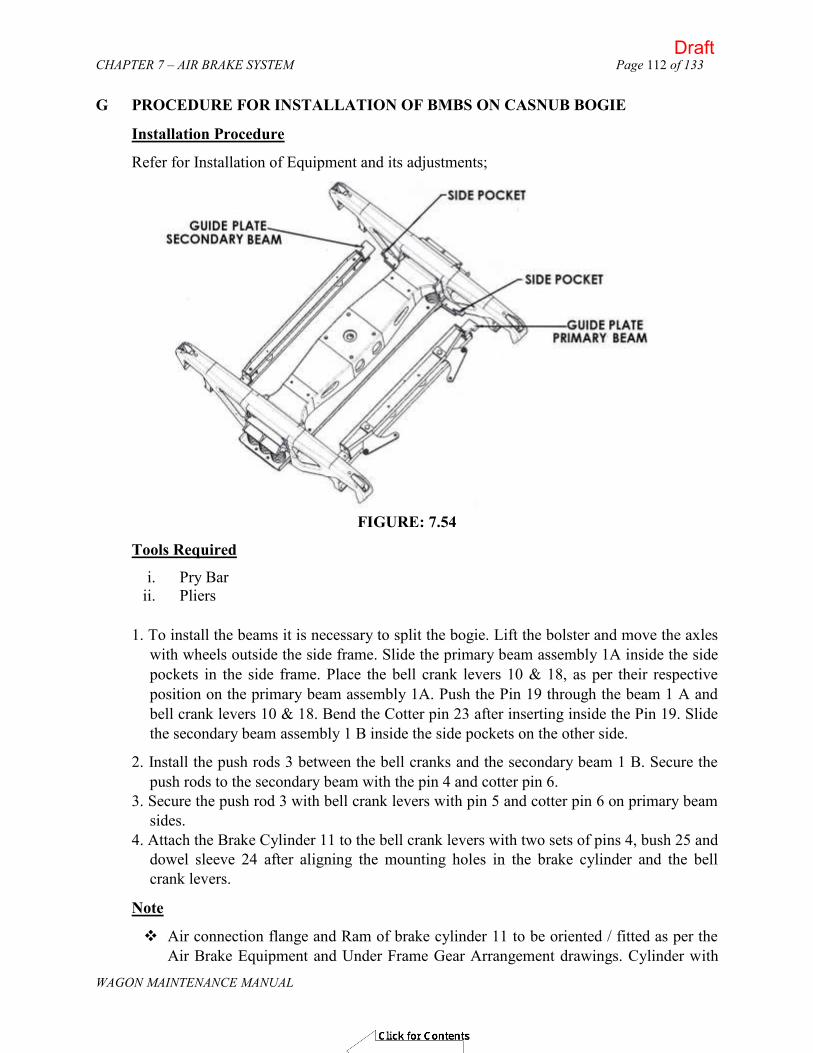
CHAPTER 7 – AIR BRAKE SYSTEM
WAGON MAINTENANCE MANUAL
Page 112 of 133
G PROCEDURE FOR INSTALLATION OF BMBS ON CASNUB BOGIE
Installation Procedure
Refer for Installation of Equipment and its adjustments;
FIGURE: 7.54
Tools Required
i. Pry Bar ii. Pliers
1. To install the beams it is necessary to split the bogie. Lift the bolster and move the axles with wheels outside the side frame. Slide the primary beam assembly 1A inside the side pockets in the side frame. Place the bell crank levers 10 & 18, as per their respective position on the primary beam assembly 1A. Push the Pin 19 through the beam 1 A and bell crank levers 10 & 18. Bend the Cotter pin 23 after inserting inside the Pin 19. Slide the secondary beam assembly 1 B inside the side pockets on the other side.
2. Install the push rods 3 between the bell cranks and the secondary beam 1 B. Secure the push rods to the secondary beam with the pin 4 and cotter pin 6.
3. Secure the push rod 3 with bell crank levers with pin 5 and cotter pin 6 on primary beam sides.
4. Attach the Brake Cylinder 11 to the bell crank levers with two sets of pins 4, bush 25 and dowel sleeve 24 after aligning the mounting holes in the brake cylinder and the bell crank levers.
Note
Air connection flange and Ram of brake cylinder 11 to be oriented / fitted as per the Air Brake Equipment and Under Frame Gear Arrangement drawings. Cylinder with
Draft

CHAPTER 7 – AIR BRAKE SYSTEM
WAGON MAINTENANCE MANUAL
Page 113 of 133
hand brake is to be installed considering the location of Bracket 16. Brake cylinder 11 ram should be in fully retracted position prior to installation.
5. Place the brake heads 7 on the guide plates of the brake beams 1A & 1 B. Secure the brake heads to brake beams with pin 8 and lock the same with cotter pin 9.
6. Assemble the bogie by lowering the bolster with side frame on the axle and wheel assembly.
7. Install new 58mm K-type brake shoe to beam assemblies (1A & 1B) on brake heads 7. Insert brake block keys 21 to hold brake blocks to the removable brake heads.
8. Connect air hose from BC pipe line to the flange on top of cylinder 11. For Brake cylinders with Hand Brake Cables
9. Bracket for cable end support is welded to a convenient place on the under frame of the wagon such that the bend radius of the cables is not less than 255 mm. (Refer under frame equipment installation drawings of the concerned wagon).
10. Attach the cable conduits to the bracket 16 by placing one nut and one washer on each side of bracket 16.
11. Tighten the lock nut to secure the cables to the bracket properly. 12. Connect both cables 13 to the cable equalizer 17 using pins 14 and cotter pins 15. 13. Connect air hose from BC pipe line to the flange on top of cylinder 11.
Hand brake rigging
14. Handbrake system requires a set of rigging between equalizer 17 and the handbrake wheel as per requirement of particular type of wagon.
15. Apply brakes, 2-3 times to the brake cylinder 11 to ensure correct piston stroke is achieved. Release air pressure.
Warning To avoid personal injury from movement of the various parts when operating the system, all personnel must be clear of Bogie and Brake pads before the cylinder is pressurized.
FIGURE: 7.55
Draft

CHAPTER 7 – AIR BRAKE SYSTEM
WAGON MAINTENANCE MANUAL
Page 114 of 133
FIGURE: 7.56
Adjustments
Adjustment is completely automatic and is accomplished by the inbuilt slack adjuster. The slack adjuster in the brake cylinder is double acting. It automatically maintains a constant piston stroke by taking up or letting out slack with each brake application. The piston stroke indicator is mounted on top of the non-pressure body of the brake cylinder. The extension of the brake cylinder ram will increase as the shoes and wheels wear. On a wagon in service, it will be clearly visible as a shiny ring near the ram scraper on the cylinder.
Components of Bogie with Hand Brake Arrangement (See Figure – 7.41)
1. Set of Brake Beams 1(A) Beam, Primary 1(B) Beam, Secondary 3) Push Rod Assy. 4) Secondary Beam Pin 5) Push Rod Pin 6) Pin, Cotter (6.3mm dia x 50mm) 7) Brake Head 8) Pin, Brake Head 9) Pin, Cotter (6.3mm dia x 75mm) 10) Lever Assy. (RH) 11) Cylinder Assy. 10" with Hand Brake
Draft

CHAPTER 7 – AIR BRAKE SYSTEM
WAGON MAINTENANCE MANUAL
Page 115 of 133
Cylinder Assy. 10" with Hand Brake 12) Piston Stroke Indicator 13) Cable Assy. 14) Pin, Cable 15) Pin, Cotter 16) Cable Bracket 17) Cable Equalizer 18) Lever Assy. (LH) 19) Primary Beam Pin 20) Brake Block 21) Brake Block Key 22) Washer, Thrust 23) Pin, Cotter (8mm dia x 50mm) 24) Dowel Sleeve 25) Bush 26) Brake Cylinder Pin
FIGURE: 7.57
Draft

CHAPTER 7 – AIR BRAKE SYSTEM
WAGON MAINTENANCE MANUAL
Page 116 of 133
Components of Bogie without Hand Brake Arrangement (See Figure – 7.41)
1) Set of Brake Beams 1A) Beam, Primary 1B) Beam, Secondary 3) Push Rod Assy. 4) Secondary Beam Pin 5) Push Rod Pin 6) Pin, Cotter (6.3 dia x 50mm) 7) Brake Head 8) Pin, Brake Head 9) Pin, Cotter (6.3 dia x 75) 10) Lever Assy. (RH)
Cylinder Assy. 10" without Hand Brake
11) Cylinder Assy. 10" without Hand Brake 12) Piston Stroke Indicator 18) Lever Assy. (LH) 19) Primary Beam Pin 20) Brake Block 21) Brake Block Key 22) Washer, Thrust 23) Pin, Cotter (8 mm dia x 50) 24) Dowel Sleeve 25) Bush 26) Brake Cylinder Pin
Procedure for changing of Brake Blocks (Refer figure 7.41)
a. Changing the brake shoe with BMBS is easy and fast. Ensure that the brakes are released. Slip in a pry bar between the brake block & wheel on anyone wheel of the bogie. Force back the brake block from the wheel, thus retracting the double acting slack adjuster and creating space for inserting new brake blocks between the brake head and wheel. To get more gap push the beam across the side pockets.
b. Remove the brake block keys and replace the brake blocks. Secure the new brake blocks with
the brake block keys. The slack adjuster will automatically adjust the brake shoe clearance to the proper value when the brakes are' applied and released. This usually takes from two to three brake applications.
Draft

CHAPTER 7 – AIR BRAKE SYSTEM
WAGON MAINTENANCE MANUAL
Page 117 of 133
FIGURE: 7.58
H PROCEDURE FOR CHANGING OF PARTS AND LIFTING OF UNDERFRAME
Isolation of Brake Cylinder a. There are two isolating cocks with vent in BC line for isolating each brake cylinder in
the wagon.
b. To isolate any particular Bogie / Brake Cylinder, move the isolating cock (OLP types) handle to closed position. This will stop the further feeding of corresponding brake cylinder and the air already present in the brake cylinder will get exhausted to atmosphere, thus, releasing the brakes in that particular bogie.
Changing of Brake Head (7) (See figure 7.40 & 7.41) a. Ensure that the brakes are released. Slip in a pry bar between the brake block 20 & wheel
on anyone wheel of the bogie. Force back the brake block from the wheel, thus retracting the double acting slack adjuster (figure-6) and creating the space between the brake block and the wheel.
b. Remove the brake block key 21 and then the brake block 20. c. After obtaining enough clearance between the wheel & the brake heads 7, remove the
cotter pin 9 & the brake head pin 8 consecutively to remove the desired brake head. d. Install a new brake head 7 and secure it with brake head pin 8 then a cotter pin 9. Bend
cotter pin legs outwards.
e. Place the brake block on the new brake head and secure the brake block with the brake block key.
f. The slack adjuster will automatically adjust the brake shoe clearance to the proper value when the brakes are applied and released. This usually takes from one to three brake applications.
Draft

CHAPTER 7 – AIR BRAKE SYSTEM
WAGON MAINTENANCE MANUAL
Page 118 of 133
Changing of Brake Cylinder (11) (See figure 7.40 & 7.41)
a. Ensure, the brakes are released and the brake cylinder is completely vented. Retract the brake cylinder 11, use pry bar between wheels & brake blocks on both, the secondary beam 1 B & the primary beam 1 A. Force the brake cylinder 11 to retract completely.
b. Disconnect the air hose from the cylinder assembly (11) flange.
c. Remove the dowel pin 24, bush 25 then rod eye pin 4 on both sides of the cylinder. Install a new brake cylinder assembly 11, being sure the cylinder is of the same size and aligned in the same way as the previous cylinder, using rod eye pin 4. Secure the brake cylinder with bush 25 & dowel pin 24.
d. Reconnect the air hose to the cylinder assembly 11 flange.
e. Apply partial brakes 2 - 3 times in order to restore the internal slack adjuster's position.
Note
For cylinders equipped with the hand brake cables (see fig. 15), it is necessary to: f. Disconnect the cable clevises from the equalizer 17 by removing the two cotter pins 15
and cable pins 14. g. Remove the two cables 13 from the cable bracket 16. Changing of Lever Assembly {RH (10) & LH (18)} (See figure 7.40 & 7.41) This change will be required if this part has been damaged or worn out.
a. Remove the cotter pin 6 and the rod clevis pin 5 with pull rod. Remove the bush 25, dowel sleeve 24 and the rod eye pin 4 with brake cylinder. Remove the cotter pin 23 and pin lever 19 with the primary brake beam 1A. Pull the bell crank lever RH 10 & .LH 18 from the beam assembly 1 A. Install a new lever RH 10 or LH 18 as applicable using the pin lever 19 and the cotter pin 23. Install pins 5 and cotter pin 6. Install pin 4 with bush 25 & dowel sleeve 24. Bend cotter pin legs.
b. The slack adjuster will automatically adjust the brake shoe clearance to the proper value when the brakes are applied and released. This usually takes from one to three brake applications.
Changing of Push Rod (3) (See figure 7.40 & 7.41) This change will be required if this part has been damaged or worn out.
a. Remove the cotter pin (6) and the rod clevis pin (5) with bell crank lever. Remove the cotter pin (6) and the pin rod eye (4) with secondary brake beam 1 B. Remove the pull rod from lever assembly RH 10 or LH 18. Pull the rod from the secondary beam. To install a new push rod, align the rod end hole with the mounting holes in the secondary beam 1 B and then insert the pin 4 and the cotter pin 6. Bend the cotter pin legs. Do the same procedure on the other end of the rod by aligning the rod with the lever assembly RH 10 or LH 18 with pin 5 and cotter pin 6.
b. The slack adjuster will automatically adjust the brake shoe clearance to the proper value when the brakes are applied and released. This usually takes from one to three brake applications.
Draft

CHAPTER 7 – AIR BRAKE SYSTEM
WAGON MAINTENANCE MANUAL
Page 119 of 133
Lifting of under frame from Bogie 1. Disconnect the air hose from the flange of brake cylinder without hand brake cables by
unscrewing the bolts.
2. Disconnect the air hose from the flange of brake cylinder with hand brake cables by unscrewing the bolts.
3. Disconnect both the cables from the equalizer cable by removing the split pins and the pins.
4. Detach the cables from the cable bracket by loosening the nuts on either side of the cable bracket. Remove the cables from the bracket after the nuts have been loosened and enough space is created for easy removal.
After the removal of brake cylinder hoses and the hand brake cables from the under frame, the wagon under frame can be lifted from the bogies.
The bogie can be dismantled or assembled with the bogie mounted parts by following maintenance instruction described earlier.
I. CONDEMNING LIMITS OF SYSTEM COMPONENTS
Brake Head (7) (See figure 7.42 & 7.43 )
FIGURE -7.59 - Brake Head
Brake Head 7 should be replaced if the following exists. Check brake head tip. Push brake head forward and measure travel by pulling brake head all the way back. Tip travel should NOT exceed 31.75 mm.
Draft

CHAPTER 7 – AIR BRAKE SYSTEM
WAGON MAINTENANCE MANUAL
Page 120 of 133
Bell Crank Lever Assembly RH (10) & LH (18) (See figure 7.42) Bell Crank Levers should be replaced if anyone of the following exists:
1. Excessive Wear on any surface Excessive is anything> 1.6 mm
2. Worn, Damaged or Broken Spherical Bearing
Worn/Enlarged Pin Holes
25.4 mm Hole exceeds 26.7 mm in any direction (i.e.: oval condition) 32 mm Hole exceeds 33 mm in any direction (i.e.: oval condition)
Push Rod (3) (See figure 7.42)
Push Rods should be replaced if anyone of the following exists: Any part of the push rod is Bent
Cracked or Damaged Welds
Excessive Wear on any surface
Excessive is anything> 1.6 mm Worn, Damaged or Broken Spherical Bearing
Worn/Enlarged Pin Hole
25.4 mm Hole exceeds 26.7 mm in any direction (ie.: oval condition) .Clevis End Gap Exceeds 27.9 mm.
Brake Beams 1 A & 1 B (See figure 7.59 & 7.60)
FIGURE -7.60– Worn Condition
Brake Beam should be replaced if the following exists.
Draft

CHAPTER 7 – AIR BRAKE SYSTEM
WAGON MAINTENANCE MANUAL
Page 121 of 133
Remove Brake Head and inspect Brake Head pin hole in Beam. If hole exceeds 20.32 mm in length, replace Beam. If not, replace brake head and recheck tip as described earlier. Tip should not exceed 31.75 mm (from FIRST check above). If tip does exceed 31.75 mm, replace Beam and Brake Head
Gap between Bell crank lever RH 10 & LH 18 and the upper channel of Primary brake beam 1A (See figure 7.61 below)
FIGURE -7.61 – Worn Condition
Measure the bell crank lever dimension with reference to the lever being supported inside the primary brake beam. Measure the maximum pass through gap.
Note the locations of the measurement for the lever and the position of the lever in regards to the primary brake beam.
Use washers as demonstrated to adjust the gap.
Draft

CHAPTER 7 – AIR BRAKE SYSTEM
WAGON MAINTENANCE MANUAL
Page 122 of 133
J. Anti Pilferage Devices (APDs)
(A) APD for Pins on Bogie Brake Cylinder
(B) APD for Primary Brake Beam
Draft

CHAPTER 7 – AIR BRAKE SYSTEM
WAGON MAINTENANCE MANUAL
Page 123 of 133
C) APD for Secondary Brake Beam
(D) APD for Push Rod
Draft
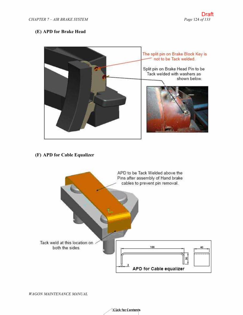
CHAPTER 7 – AIR BRAKE SYSTEM
WAGON MAINTENANCE MANUAL
Page 124 of 133
(E) APD for Brake Head
(F) APD for Cable Equalizer
Draft

CHAPTER 7 – AIR BRAKE SYSTEM
WAGON MAINTENANCE MANUAL
Page 125 of 133
(G) APD on APM
Draft

CHAPTER 7 – AIR BRAKE SYSTEM
WAGON MAINTENANCE MANUAL
Page 126 of 133
(H) Lock nut on APM
Draft

CHAPTER 7 – AIR BRAKE SYSTEM
WAGON MAINTENANCE MANUAL
Page 127 of 133
K. MAINTENANCE IN OPEN LINE
1. BOGIE RIGGING; BRAKE BEAMS, BELL CRANKS LEVERS & PUSH RODS a) Check all the pin joints for any missing parts (pins, split pins, spring dowel, etc), if
missing, provide the same. b) Check the components for missing or any physical damage, if found replace them. c) Check that the APD is provided on all the pins and on the APM. d) Check that the all hoses are properly tightened and are not threatened to be damaged by
axle or wheel. If so properly clamped them.
2. BRAKE CYLINDER a) Check for any physical damage of components or leakage. b) Check that the piston indicator is fully in released condition. c) In case of brake cylinder with hand brake cables, the cables are not entangled or resting
/ touching the axle, check that movement cable is free.
3. APM DEVICE a) Check for any physical damage to the valve. b) Check that the indicator in during the release. c) Clean the Indicator. d) Check the tightness of the lock nuts on sensor arm lever, if found loose, tighten them
and also verify the Gap as specified. e) Check that the valve's sensing arm is moving freely.
4. HAND BRAKE RIGGING
a) Check all the pin joints for any missing parts (pins, split pins, spring dowel, etc), if missing, provide the same.
b) Check the components for missing or any physical damage, if found replace them.
Spares to be maintained in open lines /ROH Depots Following items to be maintained in the open lines /ROH depot for replacement against missing or damaged parts.
Bogie Equipment S. No. Component Description Qty/ Wagon
1 Cylinder Assembly without Handbrake 1 2 Cylinder Assembly with Handbrake 1 3 APM valve Assembly 1 4 Reservoir for APM 1 5 Primary Beam 2 6 Secondary Beam 2 7 Lever Assembly ( Right Hand) 2 8 Lever Assembly (Left Hand) 2 9 Push Rod Assembly 4 10 Brake Head 8
Draft

CHAPTER 7 – AIR BRAKE SYSTEM
WAGON MAINTENANCE MANUAL
Page 128 of 133
Pins, Split Pins (Bogie Equipment)
S. No. Component Description Qty/ Wagon 1 Pin; Clevis 4 2 Pin; Clevis 4 3 Pin; Clevis 4 4 Pin; Clevis 4 5 Pin; Brake Head 8 6 Pin 16 7 Pin 4 8 Pin 8 9 Washer 4
Hoses & Hardware (Bogie Equipment)
S. No. Component Description Qty/ Wagon 1 Hose Assy. 1/2" With Flange 1 2 Hose Assy. 1" With Flange 2 3 O-Ring 2 4 O-Ring 2 5 Spring Washer 4 6 Screw, Hex Head; Zinc Plated 8 7 Washer, Lock; Cad Plated 8 8 Locknut; Zinc Plated 1 9 Screw, Hex Head; Zinc Plated 4
L. ROH SCHEDULE FOR WAGONS FITTED WITH BMBS AIR BRAKE SYSTEM
In routine overhaul, first test the brake system of BMBS using single wagon test rig. Following action should be taken for the defects / discrepancies identified during testing.
Brake Cylinders Check & replace brake cylinder by tested brake cylinder if following defects are identified:
(a) Check the brake cylinder for any physical damage or leakage.
(b) In case of brake cylinder with hand brake cables, check that the movement of cables is free
(c) Ensure that the piston indicator is in fully released condition.
Draft

CHAPTER 7 – AIR BRAKE SYSTEM
WAGON MAINTENANCE MANUAL
Page 129 of 133
BRAKE BEAMS (a) Check for any physical damage, crack, etc, if found replace them. Check for rusting &
corrosion and if found repaint them. (b) Replace all the PINS, washer, split pins, dowel pins from OEMs.
(c) Check the GAP at pivot pin on the primary brake beam as shown in the condemning limit of the system components.
(d) Check brake head for loosening or damage as shown in the condemning limit of the system components.
LEVERS & PUSH RODS (a) Replace the Bell crank lever, if any of the parameters specified in the condemning
limits is observed. (b) Replace the push rod, if any of the parameters specified in the condemning limits is
observed. APM VALVE
(a) Clean the Indicator.
(b) Check the APM valve;
Any physical damage
Valve's sensing arm is moving freely and is fully in.
Check the leakage.
Tightness of the lock nuts on sensor arm lever, if found loose, tighten them. (c) Check the Gap between the sensor arm and the side frame, if required re-adjust.
HAND BRAKE RIGGING
(a) Check the pin joints / components for missing or any physical damage, if found replace them.
(b) Replace all the PINS, washer, split pins, dowel pins, plastic bushes.
HOSES & PIPE JOINTS (a) Check the hoses for any cracks / damage. If so, replace them.
(b) Check that the hoses are properly tightened and are not threatened to be damaged by axle or wheel. If so properly clamped them.
(c) Check the pipe joints for leakages, if so, tighten them properly. M. Critical check points for wagons fitted with BMBS
SWTR Testing
1. SWTR test for wagon to be done as per RDSO format.
Draft

CHAPTER 7 – AIR BRAKE SYSTEM
WAGON MAINTENANCE MANUAL
Page 130 of 133
Bogie & Brake cylinder 1. Push rod & spring plank clearance (min 10mm). 2. The split pin over the Brake head pin is tack welded with washer. 3. The brake cylinder pins are locked with bush and dowel sleeve. 4. Split pins are provided on all pins, bent properly & provided with APDs.
APM Device
1. The APM valve is mounted properly and its sensor arm is touching in middle of side frame.
2. The gap between the sensing point and side frame bottom is adjusted as specified for the wagon and is provided with additional check nut and APD.
3. Check that the APM hose is properly tightened & secured through clamp on under-frame. Under frame & Piping
1. The BC isolating cocks in the BC line have their vent side towards the Brake cylinder (Both sides) and their handles are parallel to pipe line.
2. The brake hoses for Brake cylinder are properly secured and not resting on axle or rubbing with any other under frame members.
3. The brackets for hand brake arrangement are properly secured, the movement of the hand brake system is smooth and unrestricted.
N. POH SCHEDULE FOR WAGONS FITTED WITH BMBS AIR BRAKE SYSTEM
BOGIE RIGGING Replace all the must change items as listed in the list below on the Bogie.
BRAKE BEAMS a) Check the beams for rusting & corrosion and if found repair & repaint them.
b) Check the GAP at pivot pin on the primary brake beam as shown in the condemning limit of the system components.
c) Check brake head for loosening or damage as shown in the condemning limits of the system components.
BELL CRANKS LEVERS & PUSH RODS a) Replace the Bell Crank levers, if the critical parameters found to in condemning limits as
specified. b) Replace the Push Rod, if the critical parameters found to in condemning limits as
specified.
HAND BRAKE RIGGING a) Check for any physical damage components, if found replace them. b) Brake rigging brackets, bolts and nuts should be examined for rusting, looseness,
damaged threads, etc and replaced.
c) Replace all the pins, washer, split pins, dowel pins from OEMs. d) The plastic bushes should be changed.
Draft

CHAPTER 7 – AIR BRAKE SYSTEM
WAGON MAINTENANCE MANUAL
Page 131 of 133
BRAKE CYLINDER a) Overhaul the brake cylinder as per procedure explained in the manual. b) Replace the must change items. c) Check the condition base items, if found worn or damaged, replace them. d) Test the brake cylinder as per the procedure given in the manual.
APM DEVICE a) Overhaul the APM Device as per procedure explained in the manual. b) Replace the must change items as enlisted in the manual. c) Check the condition base items, if found worn or damaged, replace them. d) Test the APM Device as per the procedure given in the manual. e) Check the Gap between the sensor point and the side frame surface and readjust the
same as specified for the wagon type.
HOSES, PIPES & PIPE JOINTS a) Check the hoses for any cracks / damage. If so, replace them. b) Clean the pipes as per the procedure laid down by ROSO specification No. 04-ABR.
[
Must change items during POH for Bogie Mounted brake system Bogie Equipment
SNo. Component Description Qty/Wagon
1 Pin; Clevis 4
2 Pin; Clevis 4
3 Pin; Clevis 4
4 Pin; Clevis 4
5 Pin; Brake Head 8
6 Pin; 16
8 Pin; 4
9 Pin; 8
10 Washer; 4
Hand Brake Equipment
1 Pin, Cable 2
2 Pin, Tie Rod 1
3 Pin Cotter, Cable pin 2
4 Split Pin (BMBS) 1
Draft

CHAPTER 7 – AIR BRAKE SYSTEM
WAGON MAINTENANCE MANUAL
Page 132 of 133
Items to be replaced on conditional basis
SNo. Component Description Qty/ Wagon 1 Hose Assy. 1/2" With Flange 1 2 Brake Head; 8 3 Hose Assy. L" With Flange 2 4 Spring Washer 4 5 a-Ring 2 6 a-Ring 2 7 Screw, Hex Head; Zinc Plated 8 8 Washer, Lock; Cad Plated 8 9 Screw, Hex Head; Zinc Plated 4
O. Do's & Don'ts for Bogie Mounted brake System
Do’s Bogie Rigging Do ensure that the side frame pockets are of correct dimension and free of all
restriction. Do ensure that the fitment dimensions in Bogie, critical for fitment of BMBS are
maintained within their specified limits. Do ensure that all the side frame pocket liners are properly cleaned & are within the
specified limits. Do ensure there is free sliding of Brake Beams inside the side frame pocket liners. Do ensure that there is proper push rod & spring' plank clearance. If push rod
clearance is less, then check the necessary bogie dimensions. Do ensure that there is proper fitment of brake block key with Brake block and brake
head. Do ensure that there is sufficient gap (after the system is retracted) to change the
brake blocks. Do ensure to use bush and dowel pin to lock the brake cylinder pins. Do ensure that all split pin are it place and are bent properly with their arms 90° apart. Do ensure that APDs are provided on all the pins of the bogie rigging.
Brake Cylinder
Do ensure to blow the steel pipes connecting the brake cylinder before fitment to prevent the dirt particles going into the brake cylinder. This can be done by making 2-3 brake applications before connection of Hose pipe with Brake Cylinder.
Do ensure that the cables are not pulled out of the brake cylinder on making hand brake connections.
Do ensure that there is no rubbing of two hand brake cable together or resting on the axle.
Draft

CHAPTER 7 – AIR BRAKE SYSTEM
WAGON MAINTENANCE MANUAL
Page 133 of 133
APM Device Do ensure correct gap between the sensing point of APM valve & surface of side
frame. If not, then adjust the same. Do ensure to put the additional check nut on the adjusting screw to lock the same in
position. Do ensure that changeover takes place after putting 25mm block between the sensor
point and side frame. Do ensure that empty / load indicator of the APM valve (Orange coloured) is visible
during empty condition. Do ensure that the reservoir for APM valve is secured properly with the underframe.
Piping layout and fitment Do ensure proper orientation of Check Valve & Bogie Isolating Cocks. The vent side
of the isolating cock with vent should be on the brake cylinder side. Do ensure to use the correct size of bolts, screws, nuts and washers as specified. Use
of wrong size bolts / screw could damage the threads on the brake cylinder / APM valve.
Do ensure proper clamping of APM Valve hose with under frame. Do ensure that there is no rubbing of rubber hoses with axle, wheel or underframe
members. Hand Brake Arrangement Do ensure to weld the hand brake cable bracket at its correct location. It should be
welded straight and cables should be properly tightened to the bracket. Do ensure to weld the horizontal lever bracket at its correct location. Do ensure that the horizontal lever is properly supported by support brackets and
have unrestricted movement. Do ensure that there is proper hand brake arrangement movement. After applying the
hand brake, there should not be any ringing sound after striking wheels. Do ensure that there is no obstacle during return of hand brake cable after releasing
hand brake. Investigate the restriction for the cables and do the necessary rectification.
Do ensure to properly lubricate the hand brake screw, nut and pivots to reduce the friction and ensure smooth movement.
Don'ts Do not fit BMBS system if the Bogie parameters are not within the specified limits. Does not tack weld the BMBS pins / split pins on the bogie. Do not hammer on beams and brake block. Do not hit the indicator on the brake cylinder. Do not carry bogies by cranes fitted with cylinder and without wheeling, by fastened
by chain wrapped in centre. Use fork lifter or chain should hook in side frame holes only.
Do not use L-type brake blocks with Bogie Mounted Brake system. Do not use the non-standard pin, bolts for the fitment of BMBS items.
Draft

CHAPTER 8-DRAW AND BUFFING GEAR Page 1 of 36
WAGON MAINTENANCE MANUAL
(WAGON MAINTENANCE MANUAL- 2013)
CHAPTER – 8
DRAW AND
BUFFING GEAR
Draft

CHAPTER 8-DRAW AND BUFFING GEAR Page 2 of 36
WAGON MAINTENANCE MANUAL
CHAPTER 8
DRAW AND BUFFING GEAR
801. GENERAL
There are two main arrangements of draft and buffing gear in use on Broad Gauge. The older arrangement, which is found on few wagons, consists of a screw coupling with side buffers. In this design the draft load is transmitted through the screw coupling, draw hook and draw hook springs while the buffing force is borne by the side buffers. The conventional screw coupling (WA/BD-125) has a working load of 22.5t. The restrictions of size and weight limit the extent to which the draft capacity of this coupling can be improved. Recognizing this fact, the other arrangement on BG wagons is that of a Centre Buffer Coupler (CBC) which transmits both draft and buffing loads. The knuckle type centre buffer coupler was adopted for BOX, BOXN and other new design of wagons. Later on, a smaller knuckle type coupler, known as the Alliance-II coupler, was introduced for four wheeler wagons. The working strength of CBC and Alliance-II coupler is 120 tonnes and 54 tonnes respectively. CBC also has a transition version called “Transition Coupler” which incorporates a screw coupling and a pair of side buffers to permit attachment with wagons fitted with screw coupling.
The conventional Draw and Buffing gear have been phased out hence details of these
have not been included in this manual. Since now-a-days, high capacity Centre Buffer Coupler (CBC) and Draft Gear are used on BG freight stock, paras 802 to 810 have been deleted. For maintenance of draw and buffing gear 2002 version of this manual should be referred.
802. CENTRE BUFFER COUPLER & DRAFT GEAR
A) Indian Railway uses AAR type centre buffer couplers having E-type head and F-type shank for freight stock on Broad Gauge system. These couplers are generally as per requirements of AAR specifications M-201, M-205 and M- 211. The upgraded indigenous CBCs(UHTE) as per RDSO specs. No. WD-70-BD-10 are also being fitted in the wagons.
B) The draft capacity of the AAR coupler depends on the strength of knuckle, which is weakest link in the assembly. The yield strength of knuckle of material AAR M-201 Grade `C' & Grade `E' is 132 t and 180 t respectively.
C) ADVANTAGES OF AAR CENTRE BUFFER COUPLER
Coupler and buffing gear are both located together at the centre of the wagon.
Centre buffer coupler is identical at either end of the wagon and hence wagon direction is immaterial.
Coupling action between wagons is automatic. With transition arrangement, coupling with screw coupling is possible.
Draft

CHAPTER 8-DRAW AND BUFFING GEAR Page 3 of 36
WAGON MAINTENANCE MANUAL
803. PARTS OF CENTRE BUFFER COUPLER ASSEMBLY The main parts of Centre Buffer Coupler are as under:-
i) Coupler body ii) Knuckle iii) Knuckle pivot pin with washer iv) Lock v) Knuckle thrower vi) Toggle vii) Universal lock lift lever connector viii) Lock lift lever hook ix) Lock lift rivet x) Lock lift lever rivet xi) Top lifter hole cap xii) Yoke pin xiii) Yoke xiv) Yoke pin support. xv) Striker casting xvi) Striker casting wear plate xvii) Shank wear plate xviii) Yoke support plate xix) Draft Gear arrangement with front follower xx) Safety bracket with anchor plate xxi) Uncoupling gear arrangement xxii) Back stop xxiii) Clevis for Transition type coupler only xxiv) Screw coupling for Transition type coupler only xxv) Clevis pin for transition type coupler only
All parts of non-transition coupler are identical and therefore inter-
changeable with those of the transition type coupler except striker casting with wear plate and coupler body with shank. In transition CBC coupler body with shank is longer and is provided with an arrangement to fit clevis with the help of clevis pin.
804. INSPECTION OF CBC
A) Coupler and operating mechanism: When inspection of coupler and coupler operating mechanism is made, it is important to check when the coupler operating mechanism is operated to fully open the knuckle, and the knuckle is slowly closed, the lock drops freely and the mechanism returns to fully locked position. The lock position is indicated by the toggle, which is clearly visible below the coupler head.
B) Only dry lubricant shall be applied to the coupler head or the coupler head fittings. This lubricant may be applied using water, alcohol, or other non-petroleum based carrier.
Draft

CHAPTER 8-DRAW AND BUFFING GEAR Page 4 of 36
WAGON MAINTENANCE MANUAL
Draft
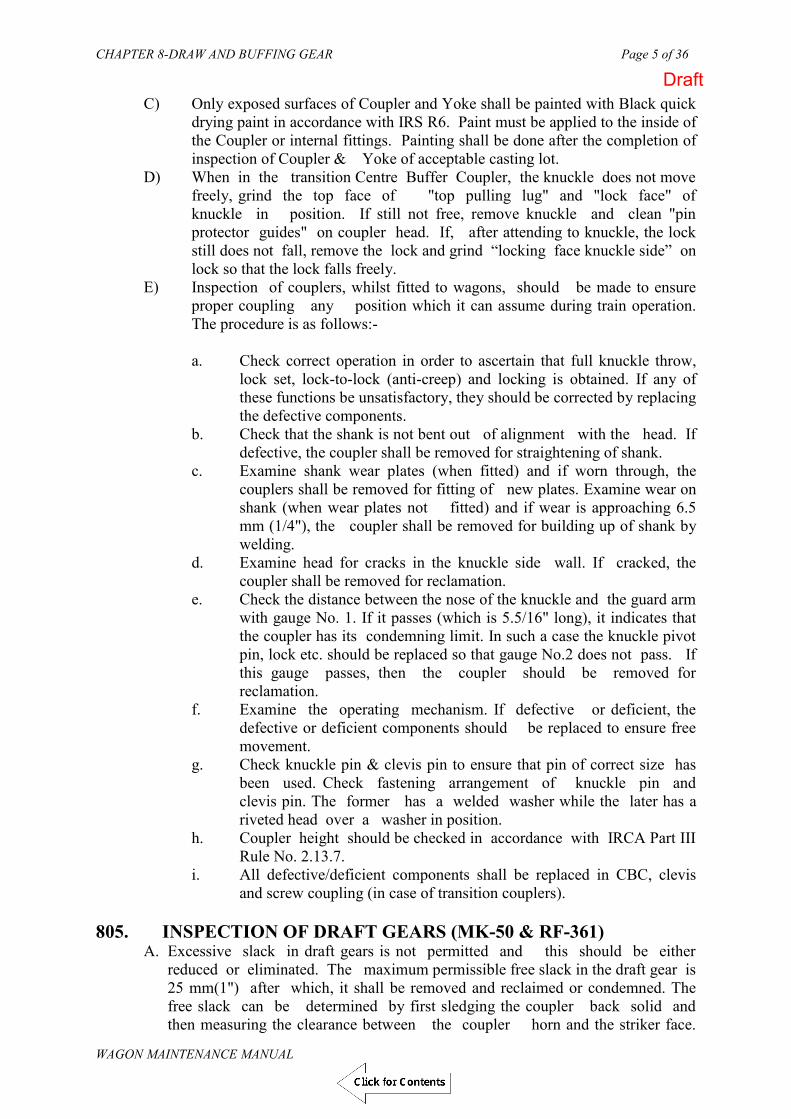
CHAPTER 8-DRAW AND BUFFING GEAR Page 5 of 36
WAGON MAINTENANCE MANUAL
C) Only exposed surfaces of Coupler and Yoke shall be painted with Black quick drying paint in accordance with IRS R6. Paint must be applied to the inside of the Coupler or internal fittings. Painting shall be done after the completion of inspection of Coupler & Yoke of acceptable casting lot.
D) When in the transition Centre Buffer Coupler, the knuckle does not move freely, grind the top face of "top pulling lug" and "lock face" of knuckle in position. If still not free, remove knuckle and clean "pin protector guides" on coupler head. If, after attending to knuckle, the lock still does not fall, remove the lock and grind “locking face knuckle side” on lock so that the lock falls freely.
E) Inspection of couplers, whilst fitted to wagons, should be made to ensure proper coupling any position which it can assume during train operation. The procedure is as follows:-
a. Check correct operation in order to ascertain that full knuckle throw,
lock set, lock-to-lock (anti-creep) and locking is obtained. If any of these functions be unsatisfactory, they should be corrected by replacing the defective components.
b. Check that the shank is not bent out of alignment with the head. If defective, the coupler shall be removed for straightening of shank.
c. Examine shank wear plates (when fitted) and if worn through, the couplers shall be removed for fitting of new plates. Examine wear on shank (when wear plates not fitted) and if wear is approaching 6.5 mm (1/4"), the coupler shall be removed for building up of shank by welding.
d. Examine head for cracks in the knuckle side wall. If cracked, the coupler shall be removed for reclamation.
e. Check the distance between the nose of the knuckle and the guard arm with gauge No. 1. If it passes (which is 5.5/16" long), it indicates that the coupler has its condemning limit. In such a case the knuckle pivot pin, lock etc. should be replaced so that gauge No.2 does not pass. If this gauge passes, then the coupler should be removed for reclamation.
f. Examine the operating mechanism. If defective or deficient, the defective or deficient components should be replaced to ensure free movement.
g. Check knuckle pin & clevis pin to ensure that pin of correct size has been used. Check fastening arrangement of knuckle pin and clevis pin. The former has a welded washer while the later has a riveted head over a washer in position.
h. Coupler height should be checked in accordance with IRCA Part III Rule No. 2.13.7.
i. All defective/deficient components shall be replaced in CBC, clevis and screw coupling (in case of transition couplers).
805. INSPECTION OF DRAFT GEARS (MK-50 & RF-361)
A. Excessive slack in draft gears is not permitted and this should be either reduced or eliminated. The maximum permissible free slack in the draft gear is 25 mm(1") after which, it shall be removed and reclaimed or condemned. The free slack can be determined by first sledging the coupler back solid and then measuring the clearance between the coupler horn and the striker face.
Draft

CHAPTER 8-DRAW AND BUFFING GEAR Page 6 of 36
WAGON MAINTENANCE MANUAL
Next by inserting a long bar between the horn and striker face, pry coupler out as far as possible and again measure the space between the horn and the striker. The difference between these two measurements is the amount of free slack.
B. Visual examination of the rubber pads & coil springs when the draft gear is in place in the wagon can be misleading and the draft gears shall therefore be inspected at every POH of the wagon, irrespective of the amount of free slack existing.
C. BOXN-HL and BCN-HL wagons are equipped with high capacity draft gears like
“MINER SL-76 Draft Gears” etc. to RDSO specification No. WD-665-BD-06.
806. REMOVAL OF COUPLER AND DRAFT GEAR FROM WAGON
A) Remove yoke pin support plate by conventional methods. Then remove the yoke pin. If necessary by inserting two chisels where the front follower bears hard against striker casting at the draft lugs.
B) The coupler will now be loose and can be pulled out. Care must be taken to
avoid personal injury as the coupler weighs over 200 Kg. and its head is heavier than the shank.
C) Remove the yoke support plate by conventional means When the gear is
loose in the wagon pocket, the gear and yoke assembly must be supported by jacks or other means to avoid personal injury.
D) To remove the gear and yoke assembly when the gear is tight in the wagon
pocket, first apply cross key through front of yoke and position in yoke pinhole. Then apply screw B in cross key A and turn until contact is made with front follower of draft gear. With wrench C, turn screw with the aid of a piece of 38 mm (1 1/2") pipe until gear is loose in the wagon pocket. Remove wrench and lower the gear and yoke assembly on supports from the wagon pocket.
FIG. 8.3 REMOVAL OF DRAFT GEAR FROM WAGONS
Fig. 9.3REMOVAL OF DRAFT GEAR FROM WAGONS
C
B
CROSS KEY 'A'
Draft

CHAPTER 8-DRAW AND BUFFING GEAR Page 7 of 36
WAGON MAINTENANCE MANUAL
E) To remove the draft gear from the yoke, compress the gear by means of screw and insert two pre-shortners as done during assembly. Then release the screw and remove draft gear.
807. COUPLER RECLAMATION PRACTICES A. COUPLER BODY
a. Coupler body with broken or missing parts shall be scrapped. Building up of worn surfaces inside the coupler head such as pulling lugs, buffing shoulders, lock wall etc. is prohibited.
b. Cracks: Cracks on the coupler body may be repaired by welding, but the
body shall be normalized after welding. Cracks in the guard arm of front face may be welded provided, they do not extend through the full thickness of the front face.
Note: After reclamation of coupler body and knuckle, check with gauge No 4 to ensure that contour has been properly restored.
B. SHANK
a. Shank Length: Shank length should be measured from the horn to the crest of the butt. It should conform to the dimensions shown in Fig. below.
FIG. 8.4 SHANK LENGTH Fig. 9.4 : SHANK LENGTH
WHEN VERTICAL DEPTH MEASURES 6 / ”OR LESS IT SHOULD BE BUILT TO NORMALDEPTH 6- / ” BY WELDING
1
3
2
4
C B
A
D
Draft

CHAPTER 8-DRAW AND BUFFING GEAR Page 8 of 36
WAGON MAINTENANCE MANUAL
If the butt is worn it may be built up by welding using suitable electrodes. After welding, surface ground reasonably smooth to fit gauges. While building up it must be ensured that the shank length is increased only by the amount B necessary to restore the dimension "yoke pin hole to butt" but must not exceed the maximum. After welding, the coupler body shall be normalized in accordance with the instructions.
Before Reclamation After Reclamation Min. Min. Max. ------------------ -------------------------------------------------------------------------
TRANSITION A. 723.9mm(28 1/2") 733.4 mm(28-7/8") 739.8mm(29-1/8") B* 98.4mm(3-7/8") 95.3+.051mm (3-3/4" + 0.002") -.8 - 1/32") C. 74.6mm(2-15/16") 84.9mm(3-11/32") 88.9mm(3-1/2") D. 173mm(6-13/16") 182.6mm(7-3/16") 185.7mm(7-5/16")
NON TRANSITION A. 546.1mm(21-1/2") 555.6mm(21-7/8") 562mm(22-1/8") B. 98.4mm(3-7/8") 95.3+ 051mm (3-3/4" + .002") - .8 - 1/32") C. 74.6mm(2-15/16") 84.9mm(3-11/32") 88.9mm(3-1/2") D. 173mm(6-13/16") 182.6mm(7-3/16") 185.7mm(7-5/16")
* No reclamation for building up of wear on dia. is permitted. However, nominal dimensions is 95.3 (+0.051mm; -0.8 mm) or 3-3/4" (+ 0.002"; - 1/32")
b. Shank depth: When vertical depth of shank is 165 mm(6 1/2") or
less, it shall be built up to the normal depth of 171 mm (6-3/4") by welding and then normalized.
c. Yoke pin hole in shank :Building up of yoke pin hole is prohibited. However, the coupler may be used until the yoke pin hole diameter reaches 98 mm.
d. Shank wear plate: When thickness of shank wear plates is 5 mm, it should be replaced by new shank wear plate.
e. Bent Shank: A bent shank may be straightened under a press after heating to 845 deg.C. Care should be taken to bring the head into proper alignment within limits and then allowed to cool in still air. Before use, the coupler body shall be carefully examined for cracks that may have developed as a result of the straightening.
C) Guard arm : Coupler body with distorted guard arm may be restored
either in a press or with light hammer blows after heating. Care should be taken to heat only a small area to prevent distortion of the opening in the front face of the coupler. After rectification the coupler body shall be normalize and then checked by Guard Arm Distortion on Gauge to Drg. No.WD-84073-S-1-RC.
D) Knuckle: (Nose wear stretch and cracks) Building up of nose wear on knuckles is hitherto prohibited. All knuckles exceeding the limits of gauge No. 3 for nose wear stretch shall be condemned.
Draft

CHAPTER 8-DRAW AND BUFFING GEAR Page 9 of 36
WAGON MAINTENANCE MANUAL
a. Knuckle Pivot Pin:- Pins having steps or cracks or which have a diameter less than 40 mm at any point shall be condemned. Bent pins may be reclaimed by heating, then straightened and allowed to cool in still air. Finally the pins shall be heat-treated to a hardness of 250-305 Brinell.
b. Knuckle Thrower:- Knuckle thrower excessively worn, broken, bent or otherwise distorted, shall be condemned.
E. Hub Wear: When hub height is less than 202.4 mm (7- 31/32"), it may be
built up by welding the bottom hub face to the maximum height allowed by gauge No.8. After welding, knuckle shall be normalized and tempered in accordance with the heat treatment instructions.
F. Pulling lug and pin protector wear. Worn pulling lugs and pin protector bosses may be built up by welding within the limits of gauges 10 (top) and 11 bottom).Top and bottom pin protector gauge No.12 (Refer RDSO's Technical Pamphlet No. G-80) for Figures of gauge ) shall be used to check the pin protector bosses separately after welding. After building up, the knuckle shall be normalized and tempered in accordance with heat treatment instructions.
G. Lock
a. Lock engagement surface wear: Wear on lock engagement surface may be built up by welding to the limits of gauge No. 9 (RDSO maintenance manual G-80). After building up, normalizing or tempering is not required.
b. Depressions found on lock as a result of contact with the knuckle or coupler body lock engagement surfaces may be built up by welding. The building up shall only be to the level of the surrounding surface of the lock face. Normalize and quench/temper in accordance with the heat treatment instructions.
c. Lock lift assembly:- Lock lift assembly excessively worn, broken bent
or otherwise distorted shall be condemned.
H. Clevis and Clevis Pin:- Clevis shall not be built up by welding. If worn more than 3 mm it shall be condemned. Pins having steps or cracks or which have a diameter less than 37 mm at any point shall be condemned. Bent pins may be reclaimed by heating, then straightened and allowed to cool in still air. Finally the pins shall be heat-treated to give a hardness of 250-305 Brinell.
I. The reclamation practice for screw couplings is similar to IRS WA2 screw coupling.
Draft

CHAPTER 8-DRAW AND BUFFING GEAR Page 10 of 36
WAGON MAINTENANCE MANUAL
808. CBC MEASURING GAUGES AND THEIR APPLICATIONS
A CHECKING OF GUARD ARM EXPANSION
GAUGE NO. 1
Apply the gauge no. 1 as shown. If gauge no. 1 passes, renew
1) Knuckle 2) Knuckle pin 3) Lock
GAUGE NO. 2
After replacing the above, if gauge no. 2 passes, renew the coupler body.
Reason - Guard arm expanded.
Draft
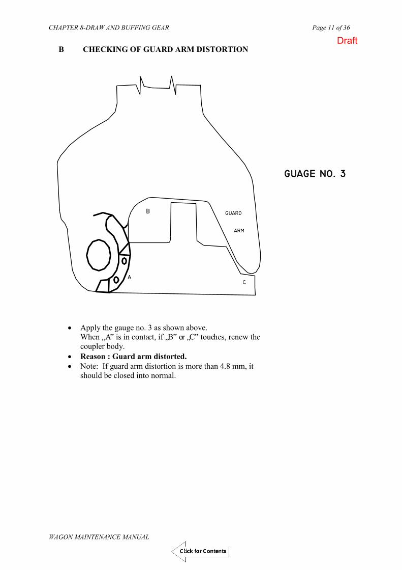
CHAPTER 8-DRAW AND BUFFING GEAR Page 11 of 36
WAGON MAINTENANCE MANUAL
Apply the gauge no. 3 as shown above. When „A‟ is in contact, if „B‟ or „C‟ touches, renew the coupler body.
Reason : Guard arm distorted. Note: If guard arm distortion is more than 4.8 mm, it
should be closed into normal.
B CHECKING OF GUARD ARM DISTORTION
Draft

CHAPTER 8-DRAW AND BUFFING GEAR Page 12 of 36
WAGON MAINTENANCE MANUAL
KNUCKLE
A B
C
D
KNUCKLE
A B
C
D
C CHECKING OF STRETCHED KNUCKLE
Apply the gauge no. 4 as shown above. When A,B,C are in contact, there must be a clear gap at „D‟
If „D” touches, renew the knuckle. Reason – Knuckle is stretched.
Draft

CHAPTER 8-DRAW AND BUFFING GEAR Page 13 of 36
WAGON MAINTENANCE MANUAL
KNUCKLE
F
G
H E
KNUCKLE
F
G
H E
D CHECKING THE KNUCKLE NOSE WEAR
Apply the gauge no. 4 as shown above. When E, F, G are in contact, „E‟ must not pass.
If „E‟ passes, renew the knuckle. Reason – Excessive knuckle nose wear.
Draft

CHAPTER 8-DRAW AND BUFFING GEAR Page 14 of 36
WAGON MAINTENANCE MANUAL
E CHECKING THE KNUCKLE LOCKING FACE
CHECKING THE KNUCKLE LOCKING FACE
Apply the gauge no. 5 as shown above. The gauge must not pass through vertically. If passes, renew the knuckle . Reason : Excessive wear at locking face of the Knuckle.
Draft

CHAPTER 8-DRAW AND BUFFING GEAR Page 15 of 36
WAGON MAINTENANCE MANUAL
F CHECKING OF ANTI-CREEP LEDGE OF BOTTOM LIFTER
Apply the gauge no. 6 as shown above. There should not be any clearance between gauge and bottom lifter. If there is a gap, renew the bottom lifter. Reason : Ineffective anti -creep
Draft

CHAPTER 8-DRAW AND BUFFING GEAR Page 16 of 36
WAGON MAINTENANCE MANUAL
G CHECKING OF ANTI-CREEP LUG OF ROTARY LEVER
Apply the gauge no. 7 as shown above. If gauge is not mating properly with the anti –creep lug
(bridge) of rotary lever , renew the rotary lever. Reason : Ineffective anti -creep
Draft

CHAPTER 8-DRAW AND BUFFING GEAR Page 17 of 36
WAGON MAINTENANCE MANUAL
H CHECKING OF LOCK WEAR
Apply the gauge no. 8 as shown above. When the surface „A‟ is in contact, if the gap is more than 3.2
mm at „B‟ , renew the lock. Reason : There is a combined wear of lock at knuckle
contacting surface & engagement surface with coupler body.
CHECKING OF LOCK WEAR
Draft

CHAPTER 8-DRAW AND BUFFING GEAR Page 18 of 36
WAGON MAINTENANCE MANUAL
809. DEVELOPMENT OF HIGH TENSILE COUPLER & HIGH CAPACITY DRAFT GEAR
On BG system, to minimize the maintenance problem and to run heavy hauled freight train, the existing grade `C' type coupler have been replaced to grade `E' type coupler known as high tensile coupler. A comparative chart of grade `C' and grade `E' coupler is given below:
Material Ultimate Yield strength AAR M-201 & Tensile strength ( in tonnes) AAR M-211 (in tonnes) STD. HT. STD. HT. STD. HT.
Coupler body Gr.B Gr.E 290 408 169 205
Knuckle. Gr.C Gr.E 251 295 132 180 Standard CBC and high tensile CBC are identical in dimension hence no problem to couple each other. Draft capacity of the high tensile coupler also depends on the weakest link i.e. knuckle. The yield strength of the knuckle is 180t compared to 132t in standard coupler. The draft capacity of HT coupler is 36% higher.
The standard draft gears are to be replaced by high capacity draft gears vide Rly. Board`s letter No.84/M(N)/172/3 Vol. I dt. 11.1.90 and 84/M(N)/172/3 dt. 5.7.90. And new freight stocks would be fitted with high capacity draft gears. At present two types of high capacity draft gears are in service
MK-50 RF-361
A. COUPLER
i. All bogie wagons manufactured prior to 1984-85 were fitted with HR-40-I or MF-400-I - IR draft gears but during shop schedules these are being replaced with high capacity draft gears progressively.
ii. At present new freight stock are fitted with high capacity draft gear i.e.
RF-361 & MK-50.
B. DESIGN FEATURES OF HIGH CAPACITY DRAFT GEARS Type Wt. Capacity Travel Reaction Performance Energy of Draft (kg) (kg.m.) (mm) force efficiency absorption Gear (tonnes) (%) (%)
MK-50 170.3 5385 81.5 269.0 23.7 86 RF-361 138.0 5725 67.8 232.3 36.6 79.6
Draft

CHAPTER 8-DRAW AND BUFFING GEAR Page 19 of 36
WAGON MAINTENANCE MANUAL
810. RF-361 DRAFT GEAR
This type of draft gear is a fully enclosed, self-contained unit assembled with pre-compression force of rubber pads, so that all parts are tight in relation to one another. Under normal service condition the draft gear is tightly fitted in yoke with front follower plate.
Note :- All the drawing no., part no. and gauge no. mentioned here under are as per literature
of Burn Standard Co. Ltd., Howrah Works, titled “INSPECTION AND MAINTENANCE MANUAL FOR HIGH CAPACITY DRAFT GEAR RF-361” A. COMPONENTS OF RF-361 DRAFT GEAR
Housing (cylinder) Wedge Shoes 3 nos Bore inserts Top follower Rubber pads (Elastomer unit) Rear wall plate
FIG. 8.5: RF- 361 DRAFT GEAR
Fig. 9.6 : RF - 361 DRAFT GEAR
Draft
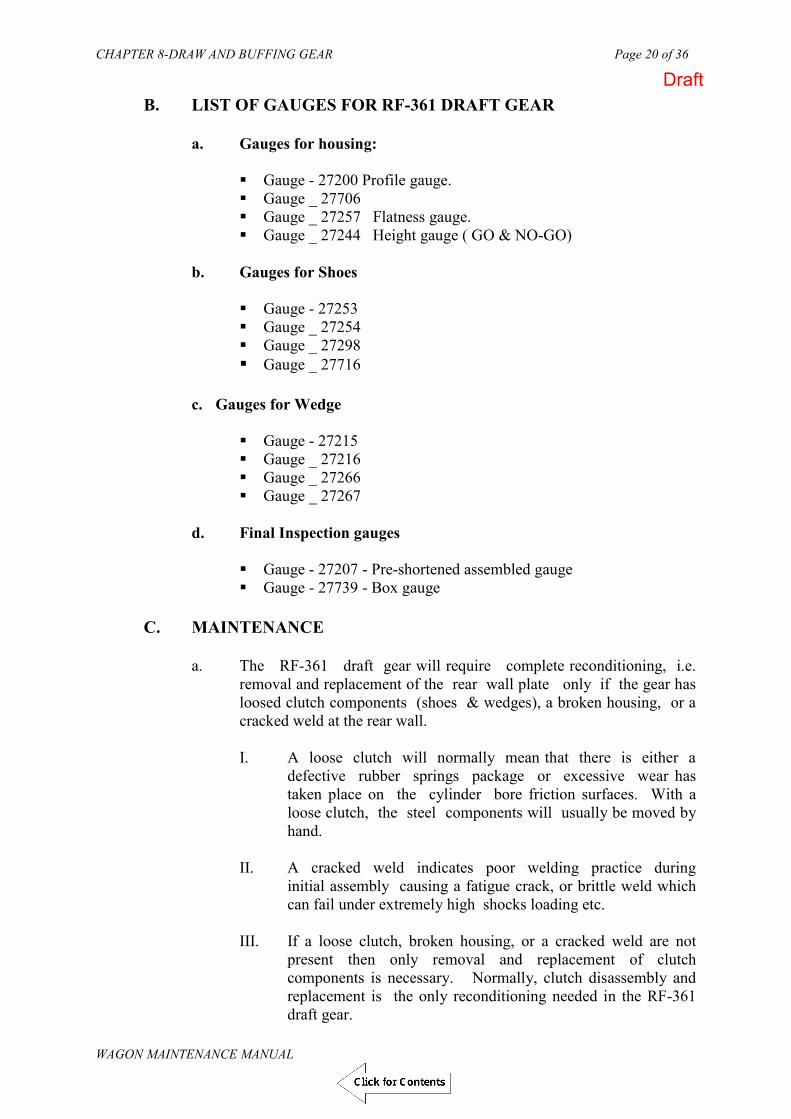
CHAPTER 8-DRAW AND BUFFING GEAR Page 20 of 36
WAGON MAINTENANCE MANUAL
B. LIST OF GAUGES FOR RF-361 DRAFT GEAR a. Gauges for housing:
Gauge - 27200 Profile gauge. Gauge _ 27706 Gauge _ 27257 Flatness gauge. Gauge _ 27244 Height gauge ( GO & NO-GO)
b. Gauges for Shoes
Gauge - 27253 Gauge _ 27254 Gauge _ 27298 Gauge _ 27716
c. Gauges for Wedge
Gauge - 27215 Gauge _ 27216 Gauge _ 27266 Gauge _ 27267
d. Final Inspection gauges
Gauge - 27207 - Pre-shortened assembled gauge Gauge - 27739 - Box gauge
C. MAINTENANCE
a. The RF-361 draft gear will require complete reconditioning, i.e. removal and replacement of the rear wall plate only if the gear has loosed clutch components (shoes & wedges), a broken housing, or a cracked weld at the rear wall.
I. A loose clutch will normally mean that there is either a
defective rubber springs package or excessive wear has taken place on the cylinder bore friction surfaces. With a loose clutch, the steel components will usually be moved by hand.
II. A cracked weld indicates poor welding practice during
initial assembly causing a fatigue crack, or brittle weld which can fail under extremely high shocks loading etc.
III. If a loose clutch, broken housing, or a cracked weld are not
present then only removal and replacement of clutch components is necessary. Normally, clutch disassembly and replacement is the only reconditioning needed in the RF-361 draft gear.
Draft

CHAPTER 8-DRAW AND BUFFING GEAR Page 21 of 36
WAGON MAINTENANCE MANUAL
b. DISASSEMBLY PROCEDURE FOR RF-361 DRAFT GEAR
If either the shoes or wedge are broken and clutch is not loose, the following disassembly procedure can be used to replace the broken components.
(I) The following equipment & special tools will be required to
remove the shoes and wedge from the draft gear;
i. 200 tonnes vertical open gap press ii. Assembly block Drg. No.27051 iii. Assembly Ring iv. A wooden taper wedge plug for the old style hollow
wedge or a 76 mm or 3" diameter industrial strength magnet with special long handle for the new solid wedge.
(II) The press should be equipped with an appropriate ram press head to
drg. no 27800 to facilitate removal operations.
III. Place the assembly ring over the top outside of the friction bore of the cylinder. Put the assembly block inside the assembly ring so that its three slegs evenly contact the three shoes. Place the magnet on top of the solid wedge, its handle protruding through the hole in the assembly block.
IV. Press down the assembly block compressing the shoes slowly into the
gear. While continuing to press on the shoes grasps the magnet or wooden plug handle and rotate the wedge clockwise until the wedge lugs are completely clear of the housing lugs. The top of the shoes need to be almost even with the bottom of the housing lugs before the rotation can be accomplished. Once the lugs are clear to each other compression can be released and wedge and shoes can be removed.
c. INSPECTION OF COMPONENTS
I. SHOES
The shoe, which have to be reused must be free from the following defects.
No concave wear on any friction surface No cracks or spalls No wear more than 0.8 mm or 1/32" on any friction surface
II. WEDGE
The wedges which have to be re-used must be free from the following defects.
Draft

CHAPTER 8-DRAW AND BUFFING GEAR Page 22 of 36
WAGON MAINTENANCE MANUAL
No crack or spall of the carburized case on the friction faces or the top of the wedge.
No wear more than 0.8 mm or 1/32" on the friction surface. No indication of broken or any cracks on any of the locking
lugs. III. HOUSING OR CYLINDERS
The inside friction bore walls must be worn symmetrical and the wall thickness must not be less than 20.6 mm or 13/16"
There must not be any bottom ridging in the bore.
Bore taper should be smooth and any concavity must not be exceed 0.8 mm or 1/32". There should not be broken lugs or cracks in the housing.
The housing should not be bulged outside.
The housing must pass through profile gauges No. 27706 and 27200.
Housing base flatness must meet gauge No. 27257.
IV. To function properly, every part of the assembly must be free of oil, grease and moisture. The parts should be kept properly during storage, handling and re-assembly.
V. Wedge and shoes are to be shot-peened to remove rust and dirt before
assembly. Shot-peening also allows better visual examination. No sharp edges are to be permitted on these parts, since they could cause cutting and gouging.
VI. For re-assembly, the assembly ring is first placed over the housing.
The three shoes are put into position in the bore, and the wedge (with magnet placed over the shoes) with each wedge lug resting on the angled shoulder of a shoe. Next, the assembly block is put over the wedge carefully, pushing the shoes into the housing. When the top of the wedge lug has cleared the bottom of the housing lug, clockwise, the wedge will fall into place and the compression can be released, completing the assembly.
D. COMPLETE RECONDITIONING
a. If complete reconditioning of the gear is required either because of a loose clutch or a broken weld, the shoes and wedge must be removed from the gear in the manner that has been described above. This reduces the internal spring force of the gear stated above.
b. The rear wall plate must be removed from the gear housing for complete
dis-assembly. The gear should be mounted in a holding fixture incorporating a hydraulic press acting axially on the housing ends. Lock the hydraulic ram about ¼” (6 mm) longer than the housing length so that
Draft

CHAPTER 8-DRAW AND BUFFING GEAR Page 23 of 36
WAGON MAINTENANCE MANUAL
the rear plate will be able to separate from the housing during cutting. The press ram must be capable of resisting a force of 10 tons exerted by the rubber pad spring stack.
c. Cutting of the rear wall plate can be done by an abrasive cut-off wheel,
sawing or flame cutting. Make the cut just less than the 1 ¼” (32 mm) thickness of the rear wall plate.
NOTE
If the flame cutting is used, adequate ventilation and air movement during the cutting must be provided. If there is a shortage of air during rubber burning, the rubber pyrolysis could create an explosive mixture.
d. Release the hydraulic ram to free the gear. Remove the rubber pads and internal follower from the housing.
e. Inspect the housing and also the housing wall thickness at the bottom
which must not be less than 11.9mm (or 15/32") and 19.8mm ( or 25/32") respectively.
f. Inspection of Rubber pads
I. Reject pads which show tears, large material chunks, large
bond failures, or extreme wear into the steel plate edges.
II. Pads are gauged and must not be less than 2 1/8” (54 mm) as measured by a gap gauge at the middle of each side.
III. Bent (but not broken or cracked) steel plates are acceptable as
these will straighten during assembly.
IV. Creases and folds are normal and are acceptable for reconditioned gears.
V. VISUAL INSPECTION OF RUBBER PADS
i. Full bonding to each of the metal is required. ii. Top and bottom surfaces of plates must be free of
elastomer films or drops. iii. Inspection sprues must be 3.18 mm or 1/8" min. below
the steel plate surface. iv. Pad must be free from cracks. v. Parting line flash should not exceed 0.78mm or 1/16". vi. Elastomeric material should be free from foreign
material i.e., trapped air etc. vii. Check for proper markings.
Draft

CHAPTER 8-DRAW AND BUFFING GEAR Page 24 of 36
WAGON MAINTENANCE MANUAL
VI. STATIC TEST
i. Rubber pads must be inspected carefully. Hundred percent pads are inspected visually. Squeeze each pad to a height of 37 mm and check for bond failure, chunks cracks and bubbles. These defects are causes for rejection.
ii. Check pads for bulge. Elastomer should not extend beyond the steel plates when squeezed to solid height.
iii. Pad must be returned to minimum free height of 61 mm within one minute after load is released.
iv. Pads must not be skewed after the load is released.
g. INSPECTION OF INTERNAL FOLLOWER
I. Outside profile dimension must be at least 111/4” x 7” (286mmx178 mm).
II. Base must be flat within 1/16” (1.6mm) across the diagonals. III. Base and show support boss must be parallel within 1/16”
(1.6mm). IV. Shoe wear indentations on the boss must not exceed 1/16” (1.6
mm).
h. INSPECTION OF FORGED ITEMS
I. Parts will be visually inspected for seams laps, scale pits, improper grinding and other defects.
II. All items should be checked for proper and distinct markings which should be legible.
III. Parts are to be gauged for dimensional checking. IV. Some dimensions are checked with calipers scales or other
measuring instruments as required if gauges do not exist or not available.
i. INSPECTION OF HOUSINGS (CYLINDERS)
I. Housings or cylinders must not have excessive porosity,
surface discontinues shrinkage and inclusions. II. proper gauges should be used to ensure sufficient yoke
clearance and for checking rear wall flatness.
j. PREPARATION OF HOUSING PRIOR TO RE-ASSEMBLY
I. The housing is placed bore end down on a flat metal work table next to a flame cutting fixture. An accurate flame cut may be achieved by using either a guided torch nozzle which moves along the stationary housing length at a fixed height, or by moving the housing past a fixed torch nozzle.
Draft

CHAPTER 8-DRAW AND BUFFING GEAR Page 25 of 36
WAGON MAINTENANCE MANUAL
II. The housing is to be cut to a length of 463.6 mm 1.6 mm (18 ¼” 1/16”). It is important to regularly clean the torch tip to help ensure a clean and accurate cut.
III. After each side is cut, the housing is hit with a hammer to remove slag. The work table and guides should be swept clean of slag after each cut to ensure a level cutting surface and proper height position for the following cuts. The housing can be rotated by hand before cutting on a new side.
IV. Check the finished housing (cylinder) height using gage no
27244.
V. Grind after cutting with a hand grinder to; Remove flame cutting marks back to clean steel Remove slag deposits on the housing Bring correct size to the finished length.
E. RE-ASSEMBLY OF RE-CONDITIONED RF-361 DRAFT GEAR
a. Tools required
50t vertical press Draft Gear assembly ring support fixture.
b. For re-assembly, the assembly ring is first placed over the housing. The three shoes are put in position in the bore and the wedge is placed over the shoes, with each wedge lugs resting on the angled shoulder of the shoes. Next, the assembly block to drg. No.27051 is put over the wedge, so the legs of the assembly block contact the top of the shoes. Press down very slowly and carefully, pushing the shoes into the housings. When the top of the wedge has cleared the bottom of the housing lugs either by tapping the handle or slightly rotating it clock- wise, the wedge will take its position in place and the compression can be released.
F. INSPECTION OF RECONDITIONED DRAFT GEARS RF-361
Draft gear shall be visually inspected for the following characteristics:- Inserts - one insert per lug properly located and intact in
position. Shoes - must be properly positioned with respect to the
wedge. Housing - must be free from cracks lumps and other defects.
Components must be properly seated. Clutch components must be tight.
Draft

CHAPTER 8-DRAW AND BUFFING GEAR Page 26 of 36
WAGON MAINTENANCE MANUAL
G. WELDING OF REAR PLATE AFTER ASSEMBLY
a. After the weld zones of the housing and rear wall plate have been suitably preheated, the heating gas is to be turned off, and the heating ring is to be removed from the housing.
b. Place the remaining two RF-8 rubber pads on the pad stack These pads will be projecting above the rear of the housing.
c. Place the preheated rear wall plate on top of the rubber stack and position it as closely as possible so the edges of the plate align with the edges of the housing.
d. Position on draft gear assembly so that it is centered directly under the ram of the press (50 tonne vertical press). This is done to ensure even loading and square closure.
e. Compress the rear wall plate down until it is firmly and squarely in contact with the housing base. Check the alignment of the rear wall plate sides in relation to the housing base sides. If necessary, release the press pressure, reposition the plate and compress again until the sides of the two pieces are aligned. It may be necessary to do this a number of times, depending on the skill and experience of the operator, till the proper alignment is obtained.
H. ROOT RUN WELDING
a. With the rear wall plate firmly held in place under the press, a root run, approximately 6.4 mm-7.9 mm (1/4"-5/16") in depth is made completely around all four sides. It is very important to obtain complete fusion and penetration into the full depth of the weld preparation.
b. MIG welding with AWS A5.18-69 class E70S-1B, 1.14 mm (0.45”) diameter, 100,000 psi tensile wire is used. Preferable shielding is a 75% Argon and 25% CO2 gas. Wire feed speed is 45.7-50.8 cm (18-20 inches) per minute and the welding machine to be set for 250 - 280 amps. 26-32 volts.
c. When the root run has been completed, the gear is removed from the press and moved aside. Inspect, to be sure that it is free of any visible defects. A total of three to four gears can be accumulated in this manner before filler pass welding is done.
I. FILLER PASS WELDING
a. The accumulated root run welded gears are placed side by side on a holding table, which is either flat or slightly tilted up to permit down hand welding of the filler pass.
b. Use MIG welding with the same wire as used in the root run. 100% CO2 shielding gas is used in the fill pass. The wire feed is 2300mm-3540mm (90-100 inches) per minute, at 250-280 Amp and 26-32 Volts.
c. Weld one side of each of the accumulated gears.
d. Turn each of the gears 90 degree and weld the second side of each gear. Continue this process till all 4 sides have been welded. The
Draft

CHAPTER 8-DRAW AND BUFFING GEAR Page 27 of 36
WAGON MAINTENANCE MANUAL
fill pass should leave a weld bead that protrudes just above the housing surface.
e. All welds are to be ground flush. The finished gear assemblies are then box gauged with Gage 27200 for dimensional acceptability.
J. PRE-SHORTENING & PAINTING
The assembled RF-361 draft gear must be pre-shortened to facilitate installation into the yoke and draft pocket.
a. Place the gear under a 200 ton open gap press, position the pre-shortening
block (Drg. no 25658) on the shoes and apply a load. Compress the gear until there is sufficient vertical clearance between the housing and wedge lugs to insert standard powdered metal. Attach tap to 3 inserts (cube) using taps lower inserts through openings.
b. Check the pre shortened length (using gauge 27207) c. After pre-shortening the external surfaces of the draft gear is to be painted
with black or blue paint. 811. MAINTENANCE OF MARK-50 DRAFT GEAR
Note: - All the drawing no., part no. and gauge no. mentioned hereunder are as per literature of M/s BESCO.
A. INSPECTION
a. The draft gear shall be inspected whenever wagons are coming in ROH depot. The following instructions shall be followed to determine whether draft gear is in normal released condition or in stuck condition.
b. A normally released draft gear would appear as shown in Fig 8.6, where the
follower plate is against the front lugs, the housing is against the rear lugs and the components of the friction clutch are fully returned to their neutral position. The internal spring forces in a normal fully released Mark 50 draft gear will be from 7,000 kg to 10,000 kg.
c. It is possible for a slight gap to be seen at either the front or rear draft lugs when the draft gear is in a normal fully released position, e.g. in an enlarged draft gear pocket.
Draft

CHAPTER 8-DRAW AND BUFFING GEAR Page 28 of 36
WAGON MAINTENANCE MANUAL
B. REMOVAL OF DRAFT GEAR FROM WAGON POCKET
When a draft gear with follower plate is installed into the pocket of a wagon, it has ample initial spring load to provide a tight fit into the draft gear pocket. While removing the draft gear from the wagon pocket, it is necessary to compress the draft gear approximately 6.35 mm (1/4”). In order to clear the front and rear stops, a suitable device can be used to compress the draft gear so that the draft gear and Yoke assembly may be free to be lowered from the wagon.
a. NORMAL CONDITION
I. Remove yoke pin support. Drop yoke pin down and draw coupler out of wagon.
II. Place suitable lifting/lowering jack under yoke support plate. Holding yoke support in position with centre-sill, cut and take out rivets.
III. Insert nut (Ref: RDSO manual G 80) in the yoke pin hole. Apply screw from the mouth and compress by rotating screw
Draft

CHAPTER 8-DRAW AND BUFFING GEAR Page 29 of 36
WAGON MAINTENANCE MANUAL
by means of wrench so that the draft gear with follower is clear of the pocket length by about 6 to 8 mm.
IV. Lower support at yoke support plate and take out yoke with draft gear and screw.
V. Unscrew and remove nut. Now draft gear, follower is loose in yoke and they can be taken out separately.
b. FOLLOWER BROKEN
A broken follower will remain within pocket only if it is cracked at centre and split in two at centre vertically or horizontally. When cracked and split jerk by hammer or by pulling yoke forward to loosen the follower in the pocket.
c. PARTIALLY STUCK GEAR
In a partially stuck draft gear, the draft gear is loose in the pocket and the draft gear travel will be less than 82.55 mm (3-1/4”).
d. FULLY STUCK DRAFT GEAR
A fully stuck draft gear is one where the components of the friction clutch are jammed and flush with the open end of the housing. A large gap would appear at the front or rear stops or at both stops. The internal spring forces between 11,000 kg and 23,000 kg would propel the friction parts outward if the gear was to suddenly release.
e. REMOVAL OF STUCK OR DAMAGED DRAFT GEAR
WARNING:
WEAR SAFETY EQUIPMENT INCLUDING HARD HAT, SAFETYGLASSES, SAFETY SHOES, GLOVES AND BODY PROTECTION
I. When follower is not missing
. DO NOT STAND OR WORK DIRECTLY IN FRONT OF COUPLER
i. First move another wagon against the couple, forcing
follower and draft gear against rear stops. Do not remove the yoke support plate. Securely weld draft gear housing and follower.
ii. Cut gear housing in spring area to expose coil springs and cut each coil of every spring to eliminate the compressive force or the springs.
Draft

CHAPTER 8-DRAW AND BUFFING GEAR Page 30 of 36
WAGON MAINTENANCE MANUAL
II. Where yoke is broken and follower is missing
i. First move another wagon against coupler forcing draft towards the stops as for as possible.
ii. Remove a section of the yoke straps with the torch to permit installation of a follower and bracket
IMPORTANT: The follower with the bracket must be installed with a lift table or fork truck to eliminate any one putting their hands near the open end of this stuck draft gear. Once fitted into place,
i. Securely weld the bracket to the draft gear housing. ii. Remove coupler. iii. Position lift table or other lowering means under
the support plate, yoke and draft gear. iv. Remove rivets from yoke support plate. Slowly lower
down the assembly unit on the ground. v. Scrap draft gear, yoke and follower.
C. REMOVAL OF STUCK DRAFT GEAR SO AS TO REUSE
In case it is desired not to gas cut and scrap stuck draft gear as above, the following procedure may be adopted:-
a. Place the stuck draft gear in front of a wall or 50 to 75 mm facing another
working draft gear with follower. Force compressed air to clean any dust or mud from draft gear.
b. Give sledge hammer blows with 8-10 kg hammer on the top front, side
fronts, edges and rear wall. The inside components will be forced out. Re-examine this draft gear for any broken or unserviceable part. Re-use or reclaim the draft gear for use.
D. INSPECTION OF MARK-50 DRAFT GEAR FOR RECONDITIONING
Mark-50 draft gears have a built in wear life gauge. This is known as "plate clearance" and can be observed by looking up at the gear while it is in the wagon When the draft gear is out of the wagon a straight edge can be placed on the centre wedge of draft gear. Both movable plates should be driven or forced down until solid before measurement is made. The plate clearance is an indicator of the total surface wear of the friction components. When the plate clearance reduces to zero, the draft gear loses its effectiveness to cushion. Once the draft gear reaches this stage, some of the parts will start wearing on the housing and cause considerable damage, rendering it impossible to recondition. Cardwell recommended that Mark-50 draft gear should be inspected whenever wagon is in shop or under repair or when the draft gears are removed from the wagon.
Draft

CHAPTER 8-DRAW AND BUFFING GEAR Page 31 of 36
WAGON MAINTENANCE MANUAL
E. SUMMARIZED GUIDE TO DISMANTLE MARK-50 DRAFT GEAR
A press of 40 tonnes is required. Press down with fixture D and insert the two pins. Remove movable plate one side. Remove wedge shoe same side. Remove movable plate other side. Remove wedge, shoe other side. Turn and remove centre wedge. Remove release spring. Remove both tapered stationary plates. Remove both outer stationary plates. Apply fixture C and press to remove pins. Remove spring seat. Remove all coil springs and corner spring seats. Reverse procedure for assembly.
F. List of Gauges For Mk-50 Draft Gear
a. Housing Gauges For Initial Inspection I. Housing reconditioned gauge No. BE-91/62-2 (No-Go Gauge to check
minimum length of housing) II. Housing reconditioned Gauge No. BE-91/62-1 (GO Gauge to check
maximum housing for Yoke and Sill clearance). III. Housing reconditioned Gauge No. BE-92/62-6 (No GO Gauge to
check minimum housing wall thickness) IV. Housing reconditioned bottom flatness check
b. Housing Weld Repair Gauges I. Reconditioned gauge No. BE-91/62-5 (No-Go Gauge to check to
centre wedge stop area) II. Reconditioned gauge No. BE-91/62-3 (Go, No-Go Gauge to check
movable plate area) III. Reconditioned gauge No. BE-91/62-4 & 5 (Go, No-Go Gauge to check
on the wedge area) IV. Centre wedge gauging gauge No. BE-91/61-1 V. Spring seat gauging gauge No. BE-91/61-5 VI. Gauging centre wedge and spring seat for sorting gauge No. BE-
91/72-1. VII. Tapered stationary plate gauge No. BE-91/61-4 VIII. Outer stationary plate gauge No. BE-91/61-3 IX. Wedge shoe gauge No.BE-91/61-2. X. Gauging springs inner coil, corner coil & release gauge No. BE-91/61-
7 & 8 XI. Outer coil gauge No. BE-91/61-6 XII. Corner spring seat reclamation. XIII. Movable plate gauging gauge No. BE-91/61-10
MG draw & buffing gear paras are being deleted. Please refer to version 2001 of Wagon Maintenance Manual, if required.
Note: There are two maintenance publications i.e. G-76 for lines staff and G-80 for
workshop staff issued by RDSO on “Inspection and Maintenance of Centre Buffer Couplers BG stock”. For Alliance-II CBC, RDSO has issued G-62 for inspection and maintenance by Train Examining and Workshop staff.
Draft

CHAPTER 8-DRAW AND BUFFING GEAR Page 32 of 36
WAGON MAINTENANCE MANUAL
VENDOR LIST
(As on 01.01.2013) (CENTRE BUFFER COUPLER)
1. HIGH TENSILE CBC COUPLER & ITS COMPONENTS FOR FREIGHT STOCK (SPEC-48-BD-08)
1. BESCO Ltd.
7B & C Poonam, 5/2 Russel Street, Calcutta-700001 2. Bhilai Engg. Corp. Ltd.
Post Box No. 31, Industrial Area, Hathkhoj Village, Bhilai-490001 3. Braithwaite & Co.Ltd.
Angus works, P.O. Angus Distt-Hoogly-712221 4. Burn Standard Co. Ltd.
Nityadhan Mukharjee Road, Howrah-711101 5. Hindustan Engg. & Industries Ltd..
27, Sir R.N. Mukharjee Road, Calcutta-700002 6. Raneka Industries Ltd.
Plot No. 17, Sector III, Sagore, Pithanm pur, Distt. Dhar M.P. 7. Texmaco Rail and Engineering Ltd.(Steel foundary)
Belgharia , 24 Paragana, Calcutta-700 056 8. Titagarh Wagon Ltd. (Unit: Titagarh steel)
113, Park Street, Calcutta-700 016. 9. Jupiter alloys & Steel
(India)Ltd. 10. Fronteir alloy & Steel Ltd., 11. Titagarh Wagon Ltd.
Heavy Engineering Division (TWL) 12. Siena Engg. PVT. Ltd. 13. Rine Engg. Pvt. Ltd. 14. Chittaranjan Locomotive Works, steel foundary, Chittaranjan 15. Rausheena Udhog Limited, Engineering Division
2. HIGH TENSILE CBC COUPLER & ITS COMPONENTS FOR LOCOMOTIVE (SPEC-56-BD-07) with amend No.1 of 10 & drawing no. SKDL-3430
1. BESCO Ltd. 7B &C Poonam, 5/2 Russel Street, Calcutta-700001
2. Chittaranjan Locomotive Works, steel foundary, Chittaranjan 3. Hindustan Engg. & Industries Ltd.
27, Sir R.N. Mukharjee Road, Calcutta-700002 4. Orient Steel Industries Ltd.
2, Brabourne Road, Calcutta-700001 5. Raneka Industries Ltd.
Plot No. 17, Sector III, Sagore, Pithanm pur, Distt. Dhar M.P. 6. Texmaco Rail and Engineering Ltd.(Steel foundary)
Belgharia , 24 Paragana, Calcutta-700 056 7. Titagarh Wagon Ltd.
113, Park Street, Calcutta-700 016. 8. Jupiter alloys & Steel
(India) Ltd.
Draft
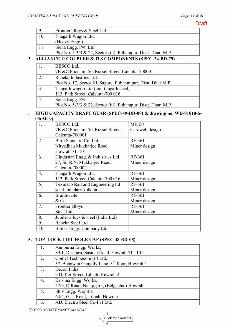
CHAPTER 8-DRAW AND BUFFING GEAR Page 33 of 36
WAGON MAINTENANCE MANUAL
9. Frontier alloys & Steel Ltd. 10. Titagarh Wagon Ltd.
(Heavy Engg.) 11. Siena Engg. Pvt. Ltd.
Plot No. 5-3/3 & 22, Sector (iii), Pithampur, Distt. Dhar. M.P.
3. ALLIANCE II COUPLER & ITS COMPONENTS (SPEC-24-BD-79)
1. BESCO Ltd. 7B &C Poonam, 5/2 Russel Street, Calcutta-700001
2. Raneka Industries Ltd. Plot No. 17, Sector III, Sagore, Pithanm pur, Distt. Dhar M.P.
3. Titagarh wagon Ltd.(unit titagarh steel) 113, Park Street, Calcutta-700 016.
4. Siena Engg. Pvt. Plot No. 5-3/3 & 22, Sector (iii), Pithampur, Distt. Dhar. M.P.
4. HIGH CAPACITY DRAFT GEAR (SPEC-49-BD-08) & drawing no. WD-81010-S-03(Alt-9)
1. BESCO Ltd. 7B &C Poonam, 5/2 Russel Street, Calcutta-700001
MK 50 Cardwell design
2. Burn Standard Co. Ltd. Nityadhan Mukharjee Road, Howrah-711101
RF-361 Miner design
3. Hindustan Engg. & Industries Ltd. . 27, Sir R.N. Mukharjee Road, Calcutta-700002
RF-361 Miner design
4. Titagarh Wagon Ltd. 113, Park Street, Calcutta-700 016.
RF-361 Miner design
5. Texmaco Rail and Engineering ltd steel foundary kolkata.
RF-361 Miner design
6. Braithwaite & Co.
RF-361 Miner design
7. Frontier alloys Steel Ltd.
RF-361 Miner design
8. Jupiter alloys & steel (India Ltd) 9. Raneka Steel Ltd. 10. Bhilai Engg. Company Ltd.
5. TOP LOCK LIFT HOLE CAP (SPEC 48-BD-08)
1. Annpurna Engg. Works, 89/1, Deshprn, Sasmai Road, Howrah-711 101
2. Comet Technocom (P) Ltd. 37, Bhagwan Ganguly Lane, 3rd floor, Howrah-1
3. Decon India, 9 Duffer Street, Liluah, Howrah-4
4. Krishna Engg. Works, 57/9, Q Road, Netajigarh, (Belgachia) Howrah
5. Shiv Engg. Woprks, 64/4, G.T. Road, Liluah, Howrah
6. AD. Electro Steel Co-Pvt Ltd.
Draft

CHAPTER 8-DRAW AND BUFFING GEAR Page 34 of 36
WAGON MAINTENANCE MANUAL
Balti kuri (Surki mill) Howrah 7. Him Teknoforge Ltd.
Village-Bhillanwali, Industries Area, Baddi (H.P.) 8. Devvrat Industries Co.
Jalan Complex, Junglepur NH-6 Mouza Baniara, P.O. Donjur, Howrah, 6. KNUCKLE PIN WITH WASHER (SPEC 48-BD-08)
1. Anand Sales Corporation 6 Poonamchand Bagaria Belly, Howrah-711005
2. Annpurna Engg. Works, 89/1, Deshprn, Sasmai Road, Howrah-711 101
3. Comet Technocom (P) Ltd. 37, Bhagwan Ganguly Lane, 3rd floor, Howrah-1
4. Cosmic Engineers, 2, Duffer Road, Liluah, Howrah-711202
5 Krishna Engg. Works, 57/9, Q Road, Netajigarh, (Belgachia) Howrah
6 Lal Baba Industrial Corporation 78, Lalababu Shir Road, Belur, Howrah- 711 202
7 Melbro Engineering Works Pvt.Ltd., 1/1, “X” Road, Belgachia, Howrah
8 NF Forging Pvt Ltd. 72, Lalababu Shire Road, Belur, Howrah 711202
9. Royal Industries, 8, Kali Mazumdar Road, Ghusuri, Howrah 711107
10. Aglow Engg. Howrah-Amta Road Salap, Howrah 911409.
11. S.K. Industries, Ichapur,P.o.Santragachi, Howrah-4
12. Shree Engineers Ichapur H.I.T. Road, Santragachi Hawrah-4
13. AD. Electro Steel Co.Pvt. Ltd. Balti kuri (Surkimill) Howrah
14. Devvrat Industries Co. Jalan Complexm, Junglepur, NH-6 Mouza: Baniara, P.o-Donjur Howrah-711411.
8. YOKE PIN (SPEC 48-BD-08)
1. Anand Sales Corporation 6 Poonamchand Bagaria Belly, Howrah-711005
2. Annpurna Engg. Works, 89/1, Deshprn, Sasmai Road, Howrah-711 101
3. Comet Technocom (P) Ltd. 37, Bhagwan Ganguly Lane, 3rd floor, Howrah-1
4. Cosmic Engineers, 2, Duffer Road, Liluah, Howrah-711202
5. Krishna Engg. Works, 57/9, Q Road, Netajigarh, (Belgachia) Howrah
6. Lal Baba Industrial Corporation
Draft

CHAPTER 8-DRAW AND BUFFING GEAR Page 35 of 36
WAGON MAINTENANCE MANUAL
78, Lalababu Shir Road, Belur, Howrah- 711 202 7. Melbro Engineering Works Pvt.Ltd.,
1/1, “X” Road, Belgachia, Howrah 8. N.F. Forging Pvt. Ltd.,
72, Lalbabu Shiv Road, Brlur, Howrah- 711 202 9. India Tools Craft Pvt Ltd.Hawrah Industries Estate, dhed No.34835
(L type) Dasnagar Howrah. 10. Devvrat Industries Co. Jalan Complex, Junglepur-NH6, Mouza=
Baniara, P.o. Donjur Howrah. 11. AD Electro steel Co. Pvt. Ltd. 12. Aglow Engg. Howrah-Amta Road
Salap, Howrah 911409. 13. Royal Industries, 8, Kali Mazumdar Road,
Ghusuri, Howrah 711107 9. KNUCKLE THROWER (SPEC 48-BD-08)
1. Annpurna Engg. Works, 89/1, Deshprn, Sasmai Road, Howrah-711 101
2. Krishna Engg. Works, 57/9, Q Road, Netajigarh, (Belgachia) Howrah
3. Lal Baba Industrial Corporation 78, Lalababu Shir Road, Belur, Howrah- 711 202
4. AD. Electro Steel Co-Pvt Ltd. Balti kuri (Surki mill) Howrah
5. Him Technoforge 6. East India Steel Pvt.Ltd. Industrial Aria, Roulkela-769004.
Note: the above vendor list is only indicative and updated by RDSO after every Six Months. The current status of the vendors may be taken from vendor directory available on the RDSO website.
Draft

CHAPTER 8-DRAW AND BUFFING GEAR Page 36 of 36
WAGON MAINTENANCE MANUAL
MARKING ON CBC (MANUFACTURERS INITIAL)
Draft

CHAPTER 8-DRAW AND BUFFING GEAR Page 37 of 36
WAGON MAINTENANCE MANUAL
FIG. 8.14: MARKING OF PARTS
Draft

Chapter 9 - TANK WAGON Page 1 of 30
WAGON MAINTENANCE MANUAL
(WAGON MAINTENANCE MANUAL- 2013)
CHAPTER – 9
TANK WAGON
Draft

Chapter 9 - TANK WAGON Page 2 of 30
WAGON MAINTENANCE MANUAL
CHAPTER 9
TANK WAGON Tank wagons form a special class of non-pooled rolling stock. They are classified according to the product carried by the tank and its design. Tank wagons fall in the following categories:
Tanks as pressure vessels.
Tanks for corrosive liquids.
Tanks for petrol and other highly inflammable products.
Tanks for middle distillates of petroleum and others products.
For information about these wagons in respect of their mechanical code and the products
carried, refer to Appendix “B” of IRCA Part III (Latest edition). Since the population of four wheeler tank wagons and tank wagons on UIC bogies have
reduced considerably and is likely to reduce further, details of these stocks have not been included in this manual. If required, 2001 version of WMM may be referred. 901. CONSTRUCTIONAL DETAILS
A. Underframe
The design of the underframe of four wheeled and eight wheeled wagon is generally similar to that of other IRS wagons except that a pair of saddles is provided on the underframe at each end for mounting the barrel. Refer to Chapter 5 for repair and maintenance of underframe.
B. Barrel and saddles
The barrel is cylindrical vessel generally fabricated out of low carbon structural steel to IS:2062 Fe 410CuW. Material specifications for various types of tanks are given in Table-9.1. The barrel is placed longitudinally on the underframe and secured by means of rivets to the saddle. The saddle is welded on underframe at each end.
Draft

Chapter 9 - TANK WAGON Page 3 of 30
WAGON MAINTENANCE MANUAL
TABLE 9.1
MATERIAL SPECIFICATION
Sr.No.
Type of wagon Cylindrical portion Dished ends
1 Ammonia tank wagon type BTALN
Steel.toBS:1501-224Gr.32ALT 50 or ASTM-516Gr-70
Steel to BS:1501-224-Gr.32 A LT 50 or ASTM-516 Gr.-70
2 Chlorine tank wagon type LCT
Steel To BS: 1501-157 Gr C Colvilles Coltuff 28
Steel To BS:1501-157 Gr C Colovilles Clotuff 28
3 Liquified petroleum gas tank wagon type BTPGLN
Steel to BS: 1501-224-Gr32 A LT 30 or ASTM-516 Gr. 70
Steel to BS: 1501-224-Gr32 A LT 30 or ASTM-516 Gr. 70
4 Sulphuric acid tank MBTSA ST.CLII M-5 Steel to IRS:M 30 5 Petrol tank wagons type TPR
TPR/A, & MBTPZ TPR-IS:2062 st42-WC MBTPZ -IS:2062 st42-
WC
IS:3747 IS:3747
6 Oil tank wagon type TORX ---do--- ---do--- 7 Heavy oil tank wagon TORX ---do--- ---do--- 8 Bitumen tank wagon type
TBT ---do--- ---do---
9 Coaltar tank wagon type TR ---do--- ---do--- 10 Petrol tank wagon type TR&
MBTP Steel to IS:2062 St. 42 WC
---do---
11 Oil tank Wagon type TO ---do--- ---do--- 12 Oil tank wagon type MBTOX ---do--- ---do--- 13 Caustic soda tank wagon type
BTCS IS:2062 Fe-410CuWA IS:5986 Fe-360 Cu
14 Hydrochloric acid tank wagon type THA
IS:2062 st-42 W IS:3747
15 Molasses tank wagon type TM & MBTM
---do--- ---do---
16 Tank wagon for phosphoric acid
ASTM A 240 55 316 L ASTM A 240 55 316 L
C. Barrel mountings and safety Fittings
Various types of barrel mountings are necessary for filling, measuring and decanting depending upon the product handled. Safety fittings are generally provided inside the dome on a diaphragm plate so as to protect them from accidental injury. These fittings as used on various types of wagons are given in Table 9.2.
Draft

Chapter 9 - TANK WAGON Page 4 of 30
WAGON MAINTENANCE MANUAL
TABLE 9.2
DETAILS OF SAFETY FITTINGS
S. N.
Description of fittings
Particulars and Mech. Code
Anhydr-ous liquid Ammonia
BTAL/BTALN
Liquified petroleum gas BTPGL/BTP
GLN
Caustic soda TCS BTCS
1. Safety valves Nos. One Two One Drg. NO MIDLAND A-3200 MIDLAND A-
3225 MIDLAND A-1739
Location Inside dome Inside dome Inside dome Vapour tight at pressure Kg/sq.cm
22.15 kg/cm2 15.85 kg/cm2 2.46 kg/cm2
Start of discharge pressure
Above 22.15 kg/cm2 Above 15.85 Above 2.46 kg/cm2
2. Safety vent with frangible disc
Nos. N/A N/A N/A Drg. No.
Location Disc not to rupture pressure kg/sq.cm Rupture pressure for disc kg/sq.cm
D. Safety valve The safety valve is provided to prevent building up of excess pressure
inside the barrel. Its fitting on the barrel is either on the diaphragm plate inside the dome or on a separate opening on the barrel. Table 9.2 shows the location, number of safety valves used and their working pressure, etc. for various types of wagons.
E. Relief valve It is a spring loaded valve fitted on the barrel of tanks for corrosive liquids.
Its main function is to release built up pressure, if it exceed the working pressure limit. Table 9.2 shows the type of wagons on which these are fitted and their working pressure limit.
F. Safety vent This consists of a frangible disc (lead or any approved material not
affected by lading) which ruptures at specified pressure. It is an additional safety fitting to safeguard against the failure of the relief valve. When the built up pressure exceeds the working pressure of the relief valve and the latter fails to function for any reason the frangible disc of this safety vent ruptures to release the pressure.
G. Compressed air valve
Draft

Chapter 9 - TANK WAGON Page 5 of 30
WAGON MAINTENANCE MANUAL
It is provided on tank wagons from which the contents are unloaded by compressed air. Its main function is to control the rate of discharge by controlling the rate of air admission.
H. Vapour extractor cock Its function is to extract vapour from the tank while filling
(Drg.No.WA/TF-2116 & WD-86081-S/60). I. Master valve assembly It is a gravity discharge valve fitted with a hand wheel in the dome for
manual operation. J. In eight wheeler stock, two bottom discharge valves are fitted, one on
either side and connected with the master valve through a tee pipe. The main function of the valve is to control the flow of the contents and also to serve as an additional safety stop in case the master valve fails or breaks. The bottom discharge valve openings are also provided with blank flanges to be used with 2mm compressed asbestos fibre jointing material to IS:2712-65 to serve as a further check on accidental leakage of contents.
902. PERIODICITY OF OVERHAULING OF TANK WAGON The periodical overhauling of IRS tank wagons should be carried out in fully
equipped mechanical workshops. The periodicity of POH is given below in Table 9.3.
TABLE 9.3
PERIODICITY OF OVERHAULING
Sr.No
Type of wagon For 1st POH For subsequent POH
Tanks for petroleum gas BTAL/BTALN 4 ½ years 4 ½ years 1. Tanks for petroleum gas BTPGL,
BTPGLN 4 years 4 years
2. BTPN 6 years 6 years
A. INTERIOR EXAMINATION OF TANK BARREL
No person should be allowed to enter the tank barrel for internal examination/repair unless the barrel is free from noxious or inflammable fumes. Therefore, before internal inspection of barrel is allowed, it must be steam cleaned/washed with solution of sodium phosphate commercial or soda ash, washed with water or other suitable cleaning agent as prescribed in case of various types of tank barrels.
Draft

Chapter 9 - TANK WAGON Page 6 of 30
WAGON MAINTENANCE MANUAL
B. STEAM CLEANING OF TANK BARRELS
The tank(s) requiring steam cleaning should be placed as near the steam supply line as possible and protected against any movement. The berthing siding should be completely isolated from all other traffic.
Tanks as pressure vessels, tanks for petroleum, other highly inflammable products, vegetable oils, bitumen, coal tar and molasses are cleaned by steam. In case of pressure vessels, it should be ensured that all the gas has been discharged to the atmosphere. After ensuring that the tank barrel is no longer under pressure, the following sequence should be followed:
i. In case of 4-wheeler tanks, remove the manhole cover together with manhole housing, valves etc. and leave the tank exposed to atmosphere for few hours. This clause is not applicable for BTPN.
ii. Entry of staff in the tank barrel should be strictly prohibited and signs with suitable legends displayed at a reasonable distances away from the tank(s) to be steam cleaned.
iii. Insert pipe through man hole and steam interior of barrel for 12 hours. In order that the tank barrel is thoroughly steamed from inside, the stem pipe should be provided with a “T” connection at its lower end and so directed as to blow steam towards both ends.
iv. Remove condensed steam collected in the tank barrel and keep the barrel exposed to atmosphere for few hours.
v. Ascertain if the tank barrel is free from gas fumes. This may be done as follows:
(a) AMMONIA TANK BARREL
Fill the tank barrel with water and take a specimen of the same in a clean glass bottle since ammonia is readily soluble in water. The specimen of water should be tested for any traces of ammonia with red litmus paper. Any trace of ammonia in water would turn red litmus blue. Another very sensitive method known as Nessler's test may be applied to find out if the specimen of water contains any traces of ammonia. In this test, the reagent used is a solution of potassium mercuric iodide with potassium hydroxide. This reagent gives a brown colour when mixed with the specimen of water containing even a minute trace of ammonia.
If ammonia is detected, empty out the tank barrel and refill with
fresh water. This process may be repeated till the tank barrel is free from ammonia traces completely.
(b) CHLORINE TANK WAGONS
Fill the tank barrel with water and take a specimen of the same in a clean glass bottle. Since chlorine is readily soluble in water, specimen of water taken out should be tested for any traces of chlorine. Any trace of chlorine in water would have a bleaching effect on coloured litmus paper. If chlorine is present, the tank
Draft
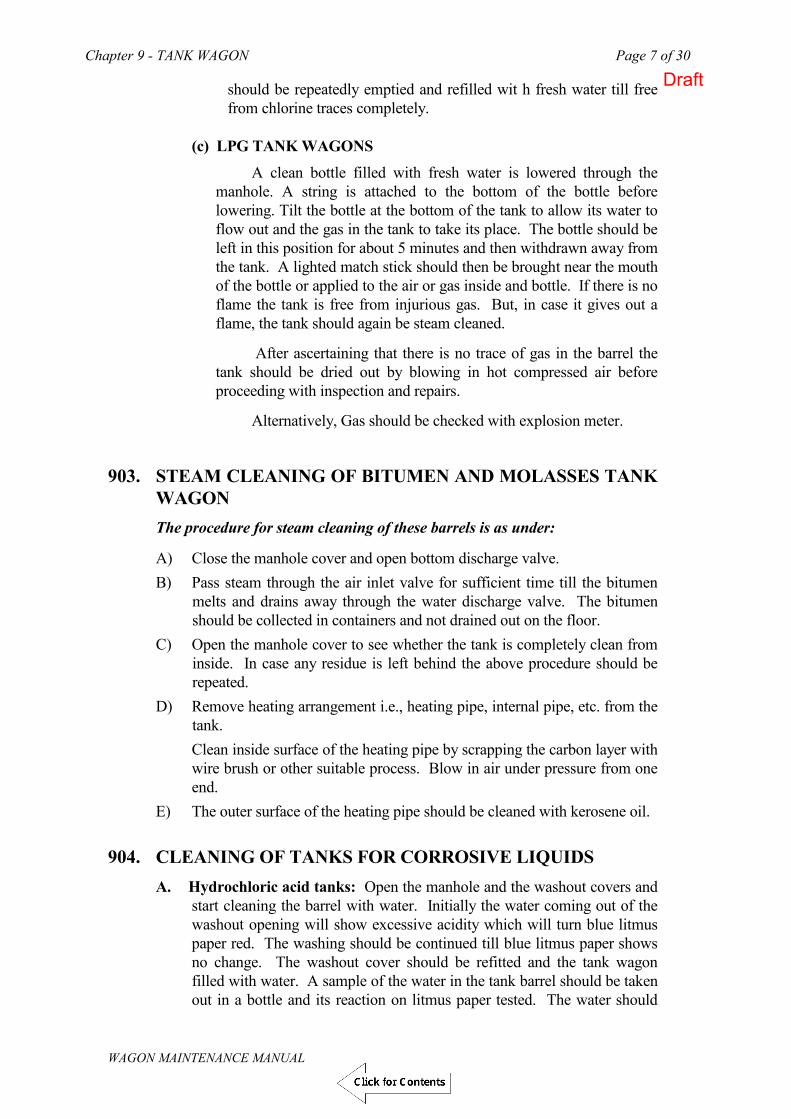
Chapter 9 - TANK WAGON Page 7 of 30
WAGON MAINTENANCE MANUAL
should be repeatedly emptied and refilled wit h fresh water till free from chlorine traces completely.
(c) LPG TANK WAGONS
A clean bottle filled with fresh water is lowered through the manhole. A string is attached to the bottom of the bottle before lowering. Tilt the bottle at the bottom of the tank to allow its water to flow out and the gas in the tank to take its place. The bottle should be left in this position for about 5 minutes and then withdrawn away from the tank. A lighted match stick should then be brought near the mouth of the bottle or applied to the air or gas inside and bottle. If there is no flame the tank is free from injurious gas. But, in case it gives out a flame, the tank should again be steam cleaned.
After ascertaining that there is no trace of gas in the barrel the tank should be dried out by blowing in hot compressed air before proceeding with inspection and repairs.
Alternatively, Gas should be checked with explosion meter.
903. STEAM CLEANING OF BITUMEN AND MOLASSES TANK
WAGON
The procedure for steam cleaning of these barrels is as under:
A) Close the manhole cover and open bottom discharge valve. B) Pass steam through the air inlet valve for sufficient time till the bitumen
melts and drains away through the water discharge valve. The bitumen should be collected in containers and not drained out on the floor.
C) Open the manhole cover to see whether the tank is completely clean from inside. In case any residue is left behind the above procedure should be repeated.
D) Remove heating arrangement i.e., heating pipe, internal pipe, etc. from the tank. Clean inside surface of the heating pipe by scrapping the carbon layer with wire brush or other suitable process. Blow in air under pressure from one end.
E) The outer surface of the heating pipe should be cleaned with kerosene oil. 904. CLEANING OF TANKS FOR CORROSIVE LIQUIDS
A. Hydrochloric acid tanks: Open the manhole and the washout covers and start cleaning the barrel with water. Initially the water coming out of the washout opening will show excessive acidity which will turn blue litmus paper red. The washing should be continued till blue litmus paper shows no change. The washout cover should be refitted and the tank wagon filled with water. A sample of the water in the tank barrel should be taken out in a bottle and its reaction on litmus paper tested. The water should
Draft
Chapter 9 - TANK WAGON Page 8 of 30
WAGON MAINTENANCE MANUAL
then be drained out. The tank wagon is now ready for internal inspection and repairs.
B. Sulphuric acid tank barrels : Sulphuric acid tank barrels should be washed with 1/2 to 1% solution of sodium phosphate commercial or half percent solution of soda ash so as to neutralize the sulphuric acid. This washing may be done as soon as possible after receiving the wagon in workshops. Since concentrated sulphuric acid absorb moisture when left open to moist air, the acid will in drop in concentration with time. It is to be remembered that dilute sulphuric acid is highly corrosive and thus, as the acid absorbs moisture, it will attack the tank barrel more vigorously. Freedom from presence of sulphuric acid can be ascertained with the help of litmus paper (if blue litmus paper turns red, the liquid contains acid). Now, rinse the tank with water, clean and dry.
Caution: As addition of water to sulphuric acid will produce intense heat, resulting in splashing due to generation of steam, the solution of commercial sodium phosphate should be added or spread gradually and with care.
C. Caustic soda tanks: These barrels should be washed free of alkalinity with hot water. Freedom from alkalinity can be easily ascertained by litmus test (if red litmus changes to blue, there are still traces of alkalinity). After it is free from alkalinity, water should be drained and barrel dried out before inspection and repairs.
905. INSPECTION OF TANK BARRELS
A. Generally tank barrel defects will be indicated by hydraulic test but it is necessary to inspect the barrel before hydraulic test so as to avoid accidental rupture of corroded barrel plates at the time of hydraulic test. The barrel should be examined by a competent inspector nominated by the CME, who must examine the interior of the barrel and the internal fittings for their general condition and freedom from wasting, wear, tear and damage. Measure barrel thickness by D-meter to ensure extent of corrosion. If the examination indicates that the corrosion/erosion has taken place to such an extent that the barrel is likely to rupture during hydraulic test, first carry out the repairs and then give a hydraulic test.
B. Inspection of rubber lining Hydrochloric acid tank wagons are fitted with rubber lining inside the barrel. The procedure for inspecting this rubber lining is as follows:
i. The barrel and its fittings are rubber lined, in accordance with code of practice for rubber lining of hydrochloric acid tank barrel. This lining should be subjected to an examination every six months.
ii. While inspecting the barrel, lining defects such as dents on the surface, cracks, and damages as well as embedding of foreign bodies should be particularly noted.
iii. It should be ensured that there are no pin holes in the rubber lining by examining the entire surface with suitable high frequency test electrodes.
Draft

Chapter 9 - TANK WAGON Page 9 of 30
WAGON MAINTENANCE MANUAL
iv. It should also be ensured that there are so crevices and peeling at the joints of the rubber sheets.
v. In cases where the condition of the lining causes doubts in respect of soundness, the firms specializing in rubber lining should be contacted for examination and necessary repairs/rectification.
vi. The rubber lining can perish if heat is applied externally to any part of the barrel. This should be borne in mind in the context of repairs by welding.
906. TESTING OF BARREL
A. Ensure that all filling lines with low pressure and other apparatuses, which should not be subjected to the test pressure, are disconnected.
B. The tank barrel and manhole orifice should then be completely filled with water at a temperature which must not exceed 38 Deg.C (100 Deg.F) during test. The barrel should be vented to prevent formation of air pockets while it is being filled. Before applying pressure, the equipment should be inspected to see that it is tight. The tank barrel should be tested by using a power driven hydraulic pump which should enable a steady increase of pressure in the tank barrel. Test pressure should be maintained for a sufficient length of time to permit a thorough examination of the barrel for any leaks.
For the purpose of this test, connection is to be made through a dummy flange with pressure gauge attached, fitted on the safety valve seating. The filling, discharge and gas valve should be tested in position on the tank in following two ways:
a) With valves closed and outlet cap off, and b) With valves open and outlet cap in position.
C. In case of any sign of leakage that may be evident from the drop in pressure
under hydraulic test, the pressure should be reduced by 20%. The lagging and insulation is removed for locating leaks. The welded seams of the tank barrel should be given a thorough hammer test by striking the plates on both sides adjacent to the weld. The plate should be struck at intervals of about 6" for the whole length of all main welded seams.
D. The hammer used for the above test should be of a material softer than the barrel plate and its edges so rounded as to prevent denting of the barrel plates. The weight of the hammer should not exceed 5 Kg.
E. The pressure should then be raised to the full test pressure and maintained for a sufficient length of time, but not less than 30 minutes. Inspect all seams and connection.
F. The tank barrel should remain secured to the underframe during this test. 907. BARREL TEST PRESSURE The testing pressures for different types of wagons are given in the following
table:
Draft

Chapter 9 - TANK WAGON Page 10 of 30
WAGON MAINTENANCE MANUAL
Description Mech. Code Hydraulic test pressure Ammonia tank BTAL, BTALN 33.25 Kg/ cm2 LPG tank BTPGL, BTPGLN 22.1 Kg/ cm2
908. TESTING OF TANKS USED FOR CORROSIVE LIQUIDS
A) The procedure for testing sulphuric acid tanks and caustic soda tanks is
the same as that given for tanks as pressure vessels above except that their testing pressure would be 4.22 Kg/cm2 (60 lbs/in2)
B) No hydraulic test should be done on a tank wagon, which is rubber lined. Such tanks should only be subjected to pneumatic test at a pressure of 2.1 Kg/ cm2. The pressure should be watched for a minimum period of 10 minutes. Drop in pressure will indicate leakage through rubber lining and barrel.
909. TESTING OF TANK WAGONS USED FOR PETROL AND
MIDDLE DISTILLATES OF PETROLEUM AND VEGETABLE OIL
The following procedure should be followed for hydraulic test of petrol tanks:
A) Remove the safety valve from its seating and fill the tank completely with water. Provide connections with the hydraulic pump through the safety valve opening. Close the manhole cover and fully tighten it. It should be ensured that the bottom discharge valve is properly closed before filling the barrel with water. The pressure should be increased gradually by means of a hydraulic pump provided with a pressure gauge. Close the control cock as soon as the hydraulic pressure reaches 2.8 Kg/ cm2 for BTPN wagons. Watch the pressure for a minimum period of 30 minutes.
B) In case of leakage (which will be evident from the drop in pressure under hydraulic test), the joints should be checked first and made tight. Thereafter, the well seems of the tank barrel should be examined thoroughly by applying soap solution, which will show up the crack or other source of leakage.
C) A similar procedure should be adopted for hydraulic testing of bitumen tank wagons except that in this case the top outlet pipe should be suitably dummied before applying any pressure. If leakage is noticed even after the joints are found satisfactory, an examination of the barrel after removal of the lagging will be necessary. Insulation should be opened only after making sure that leakage is through the tank barrel.
910. REPAIRS TO TANK BARRELS BY WELDING
A. Pressure vessels
Pressure vessels requiring repairs should be inspected by a competent authority approved by Chief Consultative Explosives. A workshop undertaking such repairs must be properly equipped for the same and facilities for radiographic examination of the repaired joints must be
Draft

Chapter 9 - TANK WAGON Page 11 of 30
WAGON MAINTENANCE MANUAL
available. The detailed procedure for repairs of pressure vessels is given in Appendix – IV.
B. Tanks for transport of corrosive liquids
i. Tanks used for transport of corrosive liquids suffer most, commonly from pitting and also have a tendency to develop cracks. Pits when not deep enough to affect the strength of the parent plate may be chipped to sound metal welded and then ground flush to the original thickness of the plate. When pits are in a close group or in one straight line and are deep enough to affect the strength of the plate, the affected area should be cut out and replaced with a let in patch.
ii. Cracks should be fully explored to ascertain their extent. The crack may be on surface or in full depth of the thickness. If possible, a portable magnetic crack detector should be used. Such detector are manufactured in the country and are a very useful piece of equipment for every railway workshop. In absence of crack detector, dye penetration test shall be performed to ascertain extent of crack. A 12mm dia hole should be drilled at the ends of the crack and the full length of the crack should then be carefully chipped and C grooved for welding. Removal of all paint, grease, oil, dirt etc. by frame heating and brushing is essential both for the purpose of proper inspection and to prevent contamination of the welded joint. Perform DP test and then do welding.
iii. After completion of welding from one side, the other side of the crack should be grooved, cleaned and welded. It is preferable if the welding is done from the inside of the barrel and is in the down hand/horizontal position. Flush ground the welded position and perform DP test along the weld.
iv. If a crack occurs in an area where the plate is wasted and of inadequate strength, the defective portion should be cut out and replaced with a let in patch. It must be ensured that the let in patch is of the same material and thickness as the parent metal. Corners of patches should be rounded to a minimum radius of 25mm and edges must be carefully prepared to obtain a V butt weld. Weld deposits should be smoothened flush with the parent metal. Perform DP test and radiography of barrel plate.
v. Rubber lined barrels should be repaired in the same manner as described above and then relined with rubber.
C. Tanks for petrol, middle distillates of petroleum, vegetable oil etc.
The repair procedure will generally be same as described above. D. Welding procedure and technique
i. Only approved brands and grades of electrodes should be used. Lists of such approved brands and grades are published by RDSO every year and these should be available in all workshops and repair depots for reference and guidance.
Draft
Chapter 9 - TANK WAGON Page 12 of 30
WAGON MAINTENANCE MANUAL
ii. Welding should be as possible done in the down hand position. Welding current (also polarity if direct current is used) should be set as recommended by the electrode manufacturer.
iii. Transverse speed of the electrodes should be controlled to obtain proper fusion of the parent metal.
iv. After every interruption of the arc, welding should be restarted ahead of the previous deposit and then moved back to fill the crater before proceeding forward again.
v. Care should be taken to remove slag before depositing successive beads.
E. Welding of stiffening plate.
Weld reinforcement should be made flush with the parent metal of the tank barrel for welding a stiffening plate.
First, tack weld the stiffening plate in the position as below. Stiffening
plate to be fitted from out side only. They should be welded with the angle in the case of old design wagons having the bearing plate inside. In case of new designs having both angle and bearing plate outside, weld with the existing bearing plate. The welding should be completed as shown in Fig. 9.1.
Draft

Chapter 9 - TANK WAGON Page 13 of 30
WAGON MAINTENANCE MANUAL
Draft

Chapter 9 - TANK WAGON Page 14 of 30
WAGON MAINTENANCE MANUAL
911. REPAIRS AND TESTING OF TANK BARREL MOUNTING FITTINGS
A. Fittings of pressure vessels
a) Safety valve
The safety valve should be given a pneumatic test. It must be vapour tight against leakage at pressures indicated in Table 9.2.
The safety valve adjustment should not be interfered with unless repairs to the valve become necessary or the valve operates incorrectly. In such cases, it must be repaired, correctly adjusted and re-tested at the pressure specified.
b) Packing and seals must be particularly checked for leaks, and those found defective or damaged, perished, should be changed. The packing should be of correct material and size/shape.
Since deteriorated seals and dirt on the seals are the most frequent cause of leakage, the seals should be given careful attention. Changing of resilient seals of liquified petroleum gas tank wagons, when the vessel is under pressure within 10 pounds of the operating pressure of the valves, should not be attempted.
c) Other fittings of pressure vessels:
i. Apart from the safety valve, each type of mounted pressure vessel has its own special fittings. The fittings are specific for each type of vessel and details regarding their examination and maintenance are contained in instructions pamphlets published by the RDSO for the respective wagons.
ii. Items to be particularly checked for defective, damaged or perished packing. “O” ring, “V” ring and lead seals. Asbestos packing or rubber packing is commonly used depending upon the type of vessels and commodity carried. V rings are pressure seals, which expand on application of pressure to remain leak proof.
iii. The various valves and fittings of these vessels are usually designed to give long periods of trouble free service and should not ordinarily require any maintenance other than cleaning. However, if a fitting become defective, it would be desirable to consult the manufacturer. Most of these valves and fittings are specialized pieces of equipment, made of special materials. Substitution by components made of incorrect materials or to wrong tolerances could have undesirable repercussions.
iv. The main fittings are two liquid education valves, a vapour education valve, a safety valve, a slip tube for determining liquid level, a pressure gauge, a thermometer well and excess flow valves which control the rate of flow through the three education valves.
Draft

Chapter 9 - TANK WAGON Page 15 of 30
WAGON MAINTENANCE MANUAL
B. PRESSURE GAUGE
In view of the possibility of pilferage/damage, the pressure gauge should be fitted only when required at the time of filling or discharging, or when the pressure is to be checked enroute. It should be removed before releasing the tank wagon. The necessary valve and fittings for attachment of the pressure gauge are provided on the manhole cover plate.
912. FITTINGS OF TANKS FOR CORROSIVE LIQUIDS
A) Pressure relief valve/safety valve: These valves should be given a pneumatic test at the pressures indicated in the table 9.2.
B) Safety vent with frangible disc: The safety vent should be provided with rubber lining of 5mm (3/16") and closed with a frangible disc which should rupture at a pressure not exceeding 3.2 Kg/cm2 (45 lbs/sq.in) for a working pressure of 2.1 Kg/ cm2 (30 lbs/sq.in). The ruptured frangible disc indicates that excessive pressures have been built up in the tank wagon and may be the first sign of malfunctioning of the safety valve. The cause needs to be investigated and removed. A ruptured frangible disc should be replaced by a new frangible disc, conforming to the required specification.
C) Globe valves/compressed air valves/washout valves: All these valves should be tested on a bench by applying hydraulic pressure by means of a pump and it should be ensured that they are leak proof at the pressures of individual wagons mentioned under “Testing of the Barrel” in para 1008 above. Leaky valves should be attended for defects before fitting body on the tank.
913. FITTINGS ON TANK WAGONS OF PETROL, OTHER INFLAMMABLE PRODUCTS, VEGETABLE OIL ETC.
A) Safety valve : These valves are provided on petrol tank wagons and bitumen tank wagons. The safety valves should be subjected to pneumatic test after repairs/POH at the pressure given.
B) Master valve: Wherever repairs to the master valve and its seating are undertaken, after filling the valve should be tested in position under air pressure of 0.35 to 0.56 Kg/ cm2 (5 to 8 psi), the tank barrel being filled with water to a minimum height of 150 cms. The hydraulic test should be carried out keeping the bottom discharge valve and blank flange open.
C) Bottom discharge valve : The bottom charge valve should also be tested in position under air pressure of 0.35 to 0.56 Kg/ cm2 (5 to 8 psi) after filling the tank barrel with water to a minimum height of 150 cm. Master valve should remain open during this test. This test to be done after satisfactory testing of the master valve.
D) Blank flange : The blank flange should be tested in the same manner as the master valve and bottom discharge valve after ensuring that a gasket of specified material has been fitted underneath.
Draft

Chapter 9 - TANK WAGON Page 16 of 30
WAGON MAINTENANCE MANUAL
914. TEST REPORTS AND RECORDS OF INSPECTION
Re-tests of all tanks, safety valves and rubber lining must be certified by the official making the tests and records maintained in the office of the CME. Certification must show railway initial, number of tank wagon, pressure to which tested, date and place of test, etc. A copy of the certificate may be submitted to the party owning the tank wagon in the case of private or dual owned tank wagons.
The testing authority must maintain detailed records of the tests carried out on each individual tank wagon.
A special report must be submitted to the CME concerned in every case
where the maximum permissible working pressure is reduced or the examination shows that the tank can not continue to be used with safety unless certain repairs are carried out immediately or within a specified time. Such a tank wagon must not be commissioned in service till it is certified fit for use after repairs and re-testing under specified pressure by the testing authority.
The testing authority competent to test the barrel, safety valve and rubber lining under the above clause is to be nominated by the CME.
915. IMPORTANT MODIFICATIONS The important modifications to be carried out in workshops and depots are
given in Table 9.4. 916. PAINTING AND LETTERING Full schedule of painting and lettering following as per standard practice as
given in Corrigenda No. 5 & 6 to IRS specification No R.6-59 as supplemented by the diagrams issued by RDSO for each such type of wagon. The test particulars must be marked at the prescribed places on the tank wagon. In case of tanks used for acids the external surface of the tank barrels should be printed with an acid-resistant paint to prevent external corrosion.
Specification of the paint should be generally as follows Ready mixed
paint brushing, bituminous black, lead free, acid, alkali, water and heat resisting for general purpose to specification IS 158-1960. While using these paints care should be taken to prepare the surface properly so that all rust loosely adherent scale and dirt are removed by means of metal scraper suitable hammer and wire brush. Grease oil etc if present should also be removed with white spirit or other suitable solvent. In case of tanks already used for carrying acid care should be taken to wash down the surface with water to remove all traces of acid and to ensure that the surface in dry before application of paint.
Draft

Chapter 9 - TANK WAGON Page 17 of 30
WAGON MAINTENANCE MANUAL
TABLE 9.4
LIST OF IMPORTANT MODIFICATIONS IN BTPN TANK WAGON
Sr.N
ITEM DESCRIPTION
Purpose Drg. No. RDSO’s REF. TO BE DONE IN SICK LINE
ROH POH NEW BUILT
1. a) Sealing Gasket
ring in the main hole & filling pipe cover
To remove the problem of sealing ring comes out from the groove
WD-86081-S/ 60 & WD-86081-S/ 61
MW/BTPN dtd. 13/16.06.2003
Yes Yes Yes Yes
2. Pin for Master valve spindle & valve operating screw
Length of the pin increased to avoid the breakage of pin
WD-86081-S/ 65 MW/BTPN dtd. 10.10.2003
No Yes Yes Yes
3. Valve spindle nut bottom
Material valve spindle nut bottom changed from IS: 1458 (bronze) to stainless steel IS: 660307r18Ni9 to avoid the nut get sheared off
WD-86081-S/ 66 MW/BTPN dtd. 10/14.10.2003
No Yes Yes Yes
4. Flanges cover design of bottom discharge pipe
Thickness of cover plate reduced to 3.15 mm from 8.0 mm & embossed at the centre for stiffness.
WD-86081-S/ 65 MW/BTPN Dt. 9/14.12.2004
Yes Yes Yes Yes
5. Filling pipe A magnet at the bottom of filling pipe provided to arrest the foreign item such as nut, bolt & locking wire etc. to avoid the damage of the seat of master valve
WD-86081-S/ 61 MW/BTPN Dt. 29/12 /6.01 2004.
No Yes Yes Yes
6. Provision of rubber piece on the barrel
To avoid the damage of dome cover during opening of cover.
WD-86081-S/ 58 MW/BTPN Dt. 22.02.2005
Yes Yes Yes Yes
7. Stiffener plate Additional stiffener plates provided on the top of centre sill and above the back portion of CBC to avoid the lifting of CBC and hitting of barrel.
WD-86081-S/ 53 & WD-86081-S/ 54
MW/BTPN Dt. 14/15.7.2005.
Yes Yes Yes Yes
8. Manhole joining Location of holes on the right side portion of manhole joining changed as correctly suggested by S. Rly.
WD-86081-S/ 61 MW/BTPN Dt. 2.04.2004
No. Yes Yes Yes
Draft

Chapter 9 - TANK WAGON Page 18 of 30
WAGON MAINTENANCE MANUAL
9. Bolster bottom flange
Bolster bottom flange profile modified and stiffener added to remove the possibility of centre sill crack as reported by JHS Workshop
WD-86081-S/ 53, WD-86081-S/ 55 & WD-86081-S/ 66
MW/BTPN dtd 07.07.2009
No. Yes Yes Yes
10.
Bogie mounted brake system
To develop the new braking system with better performance and lesser rigging parts
New Drawing No. WD-09050-S/00 to 11 (Twelve Drgs.) prepared for BMBS, other drawings will be as per WD-09050-S/00(Index).
No. No. No. Yes
Draft

Chapter 9 - TANK WAGON Page 19 of 30
WAGON MAINTENANCE MANUAL
917. EXAMINATION AND REPAIR OF TANK WAGONS BY C &W SUPERVISOR AT SICK LINE & BASE DEPOT
A) Any repairs to tank barrels should be done only at nominated sick lines where facilities for steam cleaning are available. After repairs, the barrels and valves must be tested to ensure that there is no leak. Safety valves must not be permitted with any nut or bolt deficient from sickline. The tank wagon discharge valves blank flange and manhole covers should be secured with full complement of bolts and nuts whenever the tank wagons are empty or taken out of sickline. Whenever tank wagons containing petrol or other inflammable fluids are examined, only specified safety torches (battery torches) should be used for this purpose.
B) Before any repairs are commenced on such stock, due precautions must be taken to remove all such petroleum and other inflammable fluids as required under IRCA red tariff and special instructions issued by the railway/railway board from time to time. These precautions must be observed on empty tank wagons also and no staff should be allowed to enter the tank or to bring naked light or matches near it till the tank has been steam cleaned and tested free of vapour.
The following checks should be carried out by train examining staff before a tank wagon is certified fit for loading:
a. Master valve : Leakage of master valve should be checked while keeping the bottom discharged valve open.
b. Bottom discharge valve : Proper functioning and fluid tightness of the bottom discharge valve should be ensured.
c. Blank flange : The blank flange of the correct thickness made out of steel plate and with a gasket of proper material between the blank flange and bottom discharge valve flange should be tightened by six bolts and nuts.
d. Tank barrel : Tanks with cracks on barrels should be marked sick. e. Leaky tank barrels : The leakage of tank barrels may be caused due
to one or more of the following reasons: i. Mechanical injury to the valve face and/or valve seat as a result
of foreign material, particularly nuts and bolts finding their way inside the tank wagon.
ii. Valve seats not properly secured to the stool by proper interference fits.
iii. Mal functioning of master valve.
918. PRECAUTION WITH LEAKY TANK WAGONS
A. BTAL, BTALN tank wagons
Chlorine and ammonia gases are poisonous gases and have a characteristic pungent odour, which gives warning of their presence in the atmosphere before dangerous concentrations are attained. In the case of chlorine gas, the greenish yellow colour of the gas makes it visible when high concentrations are present. In the case of ammonia, if sufficient concentration of the gas is present in the atmosphere, it will irritate the eyes and the respiratory system. As such, in the event of leakage, all
Draft

Chapter 9 - TANK WAGON Page 20 of 30
WAGON MAINTENANCE MANUAL
present in the vicinity should be warned to keep on the wind ward side of the leak.
B. BTPGL & BTPGLN tank wagon
Action in any particular case will depend upon existing conditions, and good judgement will be necessary to avoid disastrous fires on one hand and useless sacrifice of valuable property on the other hand:
a. When a tank wagon is leaking, all flames or fires near it should be extinguished or removed. No smoking should be allowed. Spectators should be kept away. Only battery operated torches or incandescent electric lights with gas proof sockets should be used.
b. Oil lanterns or signal lamps necessarily used for signalling must be kept far away and at as high an elevation as can be obtained from the tank and on the side from which wind is blowing. The vapour will go with the wind, not against it. The ash pan and fire boxes of steam locomotive are sources of danger especially when wind is blowing across the leaking tank towards them. The locomotives be moved away from the site and ash pit fires be extinguished with water.
c. The leaky tank wagon should be removed as quickly as possible to an open area where the escaping gas will be less hazardous.
d. Earth should be spread over any surface on which the LPG has leaked out in liquid form.
e. A leaky tank, which has been emptied, should under no circumstances be sent to the loading point and should be suitably stenciled as such. A leaky tank wagon must only be dealt with in a fully equipped mechanical workshop.
f. Recommended procedures to stop leaks in dome fittings: i. The liquid outlet valves face each end of the tank wagon, while the
vapour outlet valves face the sides of the wagon. If there is leakage around the valve hold down bolts, tighten the bolts until the leakage stops. If leakage persists, isolate the tank wagon and notify the oil company concerned.
ii. If there is any indication of leakage around safety valve, which is in the centre of the dome, it should first be checked whether the valve is merely performing its function, i.e., relieving excess pressure. However, if considerable flow of gas is evident, isolate the tank wagon and notify the oil company concerned.
iii. If there is leakage from the outlet of the valve, turn the valve handle by hand, if it does not stop leaking, the seat is defective. Do not try to use a wrench but insert and tighten the plug attached by a chain to the valve.
iv. If there is any leakage out of the thermometer well, the only thing that can be done is to tighten the plug. If the leak cannot be stopped, by tightening, isolate the wagon and notify the oil company. DO NOT TAKE THE PLUG OUT FOR LAPPING OF THE THREAD. The thermometer well is, in fact, a part of the shell of the tank, and if there is any evidence of leakage from the thermometer well, a bad situation is indicated. If the plug is removed when leakage is present, liquid will probably be discharged with a consequent extreme hazard.
Draft

Chapter 9 - TANK WAGON Page 21 of 30
WAGON MAINTENANCE MANUAL
v. A high percentage of any leaks that might occur will be in the gauging and sampling devices. The sampling valve is a part of a fixed line to the bottom of the tank. The valve on the gauging device (slip tube) must be used in gauging the volume of the liquid in the tank wagon. It is open while moving the gauge down to find the liquid level. Once the liquid level is found, the valve should be closed. In both cases, a turn of the shut off valve handle will probably stop any leakage that might be occurring through the valve. However, on the slip tube, which is moved up and down to determine the liquid level, there is a packing gland, which is subject to wear. If the leak is occurring through this packing gland, tighten the packing nut until the leak stops.
vi. The Junior Engineer (C&W) staff must be most careful that liquefied petroleum gas does not get on their skin. The effect is substantially the same as when dry ice comes in contact with the skin viz. freezing. The white fog of its discharge can distinguish liquefied petroleum gas while liquid can only be distinguished by careful viewing. In many cases, soapy water must be used to locate liquid leaks because they are not readily visible.
C. All other types of tanks
No leaky tank wagon should be allowed in service and such tank wagons should be attended in properly equipped sick line and/or shops.
D Additional precautions in cases of heavy leakage/spillage
In case of heavy leakage which can not be stopped by closing of valves, evaluate leaks and determine repair materials and techniques to be used. Contact nearest Rly. Station and oil installation.
The station master shall send telegraphic/telephonic advice to nearest Train Examiner & control and other authorities
Ensure that there are no ignition sources including mobile phone nearby and passers by do not smoke or carry open flame.
Isolate the heavily leaky wagons and keep as far away from the train as possible.
During isolation, take care to avoid any hammering, sparking. Have „Dangerous‟ „not be loose shunted‟ Labels affixed on both
sides of such wagons. Carden off the area.
919. PRECAUTIONS TO BE TAKEN AT LOADING AND
UNLOADING POINTS (TANKS AS PRESSURE VESSELS)
i. Ensure that the tank is loaded/unloaded under supervision of a responsible and competent person and all precautions taken by him to see that the persons engaged in the filling/discharging operations are properly protected against the poisonous gas contaminated atmosphere. A list of precautionary measures to be taken by the staff must be exhibited at a conspicuous place near the installation. The loading/unloading
Draft

Chapter 9 - TANK WAGON Page 22 of 30
WAGON MAINTENANCE MANUAL
connections must be securely attached to the pipe line before valves are opened.
ii. Ensure that the tank to be loaded/unloaded is placed in position, preferably under shade, and secured properly against any movement. The handbrakes must be put on and hand brake lever secured in that position.
iii. Shunting of any kind of the tank under loading/unloading must be strictly prohibited.
iv. Ensure that points leading to loading/unloading line on which the tank is to be loaded/unloaded are set and pad locked so as to isolate the line on which loading/unloading is to be done. If loading/unloading is to be done at one end of a long siding, it must be protected properly by a scotch block or other authorized device so as to prevent any wagon dashing against the tank wagon. It must also be ensured that shunting is not permitted on the same line when loading/unloading is being done.
v. Ensure that signs are exhibited at a suitable distance away from the tanks on the approach end or both ends as applicable.
vi. Ensure that the tank is filled by connections to the liquid valves, which have dip pipes to the bottom of the tank. The other gas valve is connected to the absorption system of the chlorine plant or Ammonia plant. In the case of LPG tanks, two liquid valves are provided for loading/unloading of the tank. The rate of flow of LPG liquid becomes too great in case only one liquid line is provided and this may result in the excess flow valve (provided inside the pipes below the diaphragm plate) closing off. Use of only one valve may result in closing down of excess flow valve repeatedly.
vii. The tank should not be loaded beyond its marked capacity under any circumstances.
viii. Tank wagon(s) must not be allowed to stand with loading/unloading connections attached after loading/unloading is completed.
ix. Throughout the entire period of transfer operations or while the tanks connected to loading/unloading devices, the tank(s) must be continuously attended to by the operator.
x. If it is necessary to discontinue transfer operations for any reasons, all loading/loading connections must be tightly closed and closure of all other concerned components strictly ensured.
xi. On completion of filling operation, the valves should be properly closed and dome cover sealed. The caution signs should then be removed and padlocks on the points opened to enable the tank(s) to be taken out for attaching to trains.
xii. The loading of pressure gas tank wagons must be carried out by using a gas compressor i.e. the compressor will be connected to the gas valve on the tank. The liquid valve on the tank will be connected to the storage tank. By ensuring that the pressure in the tank barrel is about 10 lbs/sq.in (gauge) above the pressure in the storage tank, the liquid gas will discharge itself. To avoid reverse siphoning of the liquid gas into the tank barrel, the above pressure must be maintained inside the barrel till such time the whole contents are discharged.
Draft

Chapter 9 - TANK WAGON Page 23 of 30
WAGON MAINTENANCE MANUAL
xiii. While discharging, the pressure inside the tank barrel should be maintained steady so as to avoid any chance of sudden evaporation and consequent chilling of the barrel plates.
xiv. When all the liquid gas has been transferred, which will be indicated by the level ceasing to rise in the storage tank, the liquid valve on the tank must be closed.
xv. All tools and implements used in connection with transfer operations must be kept free from oil, grease, dirt and grit.
xvi. Seals and other substances must not be thrown into the tank. Care must also be taken to avoid spilling of the contents over the tank.
920. LOADING AND UNLOADING CORROSIVE LIQUIDS
i. Only concentrated sulphuric acid of concentrations 80% or 85% and above is to be loaded in a wagon. Dilute sulphuric acid of lower concentrations if loaded will corrode the tank since the latter is unprotected/unlined from inside. No chemical other than concentrated sulphuric acid should be loaded in a wagon. Caustic soda lye (liquor) having specific gravity of 1.51 at 150C or a concentration of not less than 48% and containing not more than 3% of any chloride and no free chlorine, is loaded in the caustic soda tanks.
ii. Before loading it should be ensured that the tank barrel and washout valve is free from any leaks and the dome cover fits airtight. A leaky tank wagon should not be allowed to run on line and it should be suitably marked for repairs after unloading. Dome fittings should be inspected for leaks and other defects before unloading to avoid acid spillage or spraying.
iii. An air space of not less than 5% of the capacity of the tank should be left. When higher concentrations are filled, it should be ensured that tank wagon is not overloaded beyond its carrying capacity in tonnes.
iv. All empty tank wagons should be securely closed airtight as sulphuric acid is self-diluting and absorb moisture from atmosphere. Dilute sulphuric acid is highly corrosive to mild steel.
v. During the loading and unloading operations, caution signs must be exhibited at a suitable distance away from the tank on the approaches at both ends.
vi. Smoking or bringing a naked flame or lamp near sulphuric acid wagons is strictly prohibited. An incandescent electric light with gas proof socket should be used.
vii. At the time of loading/unloading, the tank wagons should be protected by means of scotch blocks or other suitable devices to prevent any risk of damage due to inadvertent shunting.
viii. Steel spanners/tools should not be used as they may cause sparks on striking, Brass tools may be used.
ix. All spillage of acid should first be neutralized by means of hydrated lime and washed down the drain with an adequate supply of water.
x. The tank wagon has a top discharge arrangement. For loading the tank it should be connected to an air compressor through the globe valve and it must be ensured that the pressure in the tank does not rise above 30 psi. The discharge pipe should be connected to the designated line after
Draft

Chapter 9 - TANK WAGON Page 24 of 30
WAGON MAINTENANCE MANUAL
removal of the blank by means of a suitable flange after inserting a rubber gasket/lead lining. The gasket/lead lining prevents spillage of acid on the tank barrel.
xi. The filling in of the tank wagon is also effected through the discharge pipe by connecting it to the consignee's acid supply pipeline by means of a suitable flange after inserting a rubber gasket/lead lining. During the filling in operation, the globe valve/air compression valve should be in open position to permit exit of air from the tank.
921. LOADING AND UNLOADING OF TANK WAGONS
i. Hydrochloric acid has a characteristic pungent odour, which gives warning of its presence. All unprotected contact with the hydrochloric acid fumes should be avoided.
ii. No chemicals other than hydrochloric acid should be loaded in Hydrochloric acid type tank wagons.
iii. Adequate supervision of filling and emptying of wagons is necessary to ensure that this is done in an authorized manner only.
iv. The filling should be done from the filling and discharge pipe. This pipe is provided with a rubber lined flange. A corresponding flange should make the connection to the acid supply line after inserting a rubber gasket between the filling flange and the supply flange. The gasket prevents spillage of acid on the tank barrel and would also prevent damage to the rubber lining on the filling/delivery flange.
v. In order to give vent to the air inside the tank barrel, the air flange should be removed for the filling operation.
vi. The decanting should be done after connecting the delivery pipe to the discharge flange. Connecting with the help of a suitable flange using a rubber gasket should do this.
vii. The air pipe flange should be removed and a pneumatic line should be connected to the air pipe, by means of a suitable flange after inserting a rubber gasket.
viii. The pneumatic pipeline should be connected to a pneumatic system wherein the pressure in the line cannot exceed 1.75 Kg/cm2 (25 psi). This is done to prevent damage to the tank barrel.
ix. After the tanks have been unloaded, they should be filled with clean water at a temperature not exceeding 380 C (1000 F). This is done to prevent deterioration of the rubber lining as the rubber decomposes in presence of air.
x. All spillage of acid should be washed down the drain with an adequate supply of water. If the spillage is excessive, the acid should first be neutralized by means of hydrated lime.
922. PRECAUTIONS FOR TANKS FOR PETROLEUM AND OTHER INFLAMMABLE PRODUCTS
A. At loading points
i. Ensure that all tank fittings are in good working condition. ii. Ensure that tank fittings are provided with requisite anti-
pilferage devices.
Draft

Chapter 9 - TANK WAGON Page 25 of 30
WAGON MAINTENANCE MANUAL
iii. Ensure that the safety valve is intact and properly sealed. iv. Ensure that the master valve is fluid tight. v. Ensure that the bottom discharge valve is fully closed and fitted
with a blank flange and gasket before commencement. vi. Ensure that the vapour extractor cock and vent plug are open
before commencement of loading. vii. Ensure that loading is done through the filling pipe only. viii. Ensure that recommended air space as specified for the
particular petroleum product is provided and that payload does not exceed the permissible limit.
ix. Remember to close the vapour extractor cock after loading. x. Remember to fit the cap on the vapour extractor cock after
loading. xi. Remember to fit the cap on the filling pipe after loading. xii. Ensure closure of the vent plug cock after loading. xiii. Provide proper sealing when dome cover eye bolt nuts are
tightened. xiv. Make sure that the dome cover is closed after loading.
B. At unloading points
i. Close the master valve after unloading. ii. Close the bottom discharge valve after unloading. iii. Fit the dummy flange with gasket and all its bolts back in
position after unloading. iv. Close the dome cover after unloading. v. Tighten eye bolt nuts of dome cover after unloading. vi. Do not allow rough, hump or loose shunting. vii. Do not allow unauthorized persons to operate valves. viii. Do not allow any person to enter the tank barrel for internal
examination/repairs unless the barrel has been steam cleaned. ix. Do not undertake repair of the tank barrel by welding unless it
is properly steam cleaned. x. Do not start welding repairs on a tank wagon fitted with roller
bearings unless the barrel is properly earth and roller bearings are short circuited.
xi. Do not allow tank wagon to move from loading/unloading points unless the tank fittings are properly refitted and dome cover closed.
C. Action to be taken in case of fire:
Eliminate source of ignition. Organize dispersal of vapour. Cut-off source of leakage to extinguish fire. Allow the fire to continue under controlled conditions, till all the
fuel is burnt. Use water spray to cool equipment on fire and adjacent
equipments. Not to extinguish flame at leak to avoid uncontrolled explosive re
ignition. Inform all concerned depending upon gravity of fire.
Draft

Chapter 9 - TANK WAGON Page 26 of 30
WAGON MAINTENANCE MANUAL
Contact LPG bottling plants for assistance in case of emergency 923. PRECAUTIONS FOR BITUMEN TANKS
A. Loading
i. The tank wagon offered for loading must be examined for any signs of leakage through the gaskets or flange stud holes. Tank wagons having any signs of leakage should be rectified before being offered for loading bitumen.
ii. Place the wagon at the proper loading point and ensure that the bottom discharge valve is properly closed. Load the bitumen through the manhole cover. Fill the tank to about 1/3rd of its capacity and then stop loading for about half-an-hour. Check for leakage through the studs or gaskets provided at the end of the barrel, if any. Tighten the nuts all this stage if leakage is noticed through the gaskets/stud holes.
iii. Start loading again upto marked capacity. Close the manhole cover tightly.
B. Unloading
The wagon to be unloaded should be placed as near as possible to the storage tank in which it has to be unloaded. Open the mouth of the internal pipe and fix the burner centrally on the flanges. Ignite the burner and adjust the flame suitably for correct combustion to get a long blue flame. After heating for half-an-hour, check if any leakage is noticed through the studs and gasket provided at the end of the barrel. Tighten the nuts to stop the leakage. Check leakage from the bottom discharge valve. If leakage is found, close the valve tightly. Heating should be continued till such time the temperature rises to 150-1600 C. Stop the burners and connect the air inlet valve of the wagon to the compressor. The top discharge valve should be connected with the storage tank with proper sealing and tightening of the nuts to ensure against leakage through these connections. The man hole cover along with its sealing ring must be secured tightly to avoid leakage. Unloading of the Bitumen from the tank should be completed in one stretch. During unloading, compressed air pressure should be maintained between 12 to 15 lbs/sq.in. It should be ensured that the tank is completely drained of its contents before releasing it. After unloading, the cover plate on the mouth of the internal pipe should be refitted.
924. MAINTENANCE AND REPAIR IN SICK LINE
A) No person should be allowed to enter the tank barrel for internal examination/repair unless the barrel is free from noxious or inflammable fumes. Therefore, before internal inspection of barrel is allowed, it must be steam cleaned/washed with solution of sodium phosphate commercial or soda ash and washed with water or other suitable cleaning agent as prescribed in case of various types of tank barrels.
Draft
Chapter 9 - TANK WAGON Page 27 of 30
WAGON MAINTENANCE MANUAL
B) Before any repairs are commenced on such stock, due precautions must be taken to remove all such petroleum and other inflammable fluids as required under IRCA red tariff and special instructions issued by the Railway/Railway Board from time to time. These precautions must be observed on empty tank wagons also and no staff should be allowed to enter the tank or to bring naked light or matches near it till the tank has been steam cleaned and tested free of vapour.
C) Any repairs to tank barrels should be done only at nominated sick lines where facilities for steam cleaning are available. After repairs, the barrels and valves must be tested for leak. Safety valves must not be permitted with any deficient nut or bolt from sickline.
D) The tank wagon discharge valves blank flange and manhole covers should be secured with full complement of bolts and nuts when the tank wagons are released from sickline.
E) Whenever tank wagons containing petrol or other inflammable fluids are examined, only specified safety torches (battery torches) must be used for this purpose.
F) In addition to routine attention to underframe, suspension, running gear, draw gear, buffing gear and braking gear, the following examinations and repairs to be done in sickline :-
i) Examination of tank barrels. ii) Testing of discharge valves and barrels to ensure that there is no
leak. iii) Adjustment and examination of security fittings of safety valves iv) Examination of tank barrel insulation where provided. v) Examination of dome equipment vi) Examination of barrel, cradles and fastening arrangements
G) The checks as mentioned in para 918 B must be carried out by train examining staff before a tank wagon is certified fit for loading.
H) Testing of barrel is to be done as given in para 906.
I) Procedure for repairs of tank barrel to be followed as given in para 910.
J) The important modifications to be carried out in depots are given in Table 9.4.
K) The painting and lettering to be done as given in para 917.
925. MAINTENANCE AND REPAIR IN WORKSHOP DURING
POH
The periodical overhauling of IRS tank wagons should be carried out in fully equipped mechanical workshops. The periodicity of POH (refer IRCA Part III Rule 2.4.3) is given in Table 9.3. For various type of tank wagons, detailed maintenance procedure is given is RDSO publications listed in Table 9.5. The detailed procedure for repair of tank wagon pressure vessels is also described in Appendix-IV.
Draft

Chapter 9 - TANK WAGON Page 28 of 30
WAGON MAINTENANCE MANUAL
926. Instruction for Maintenance and Operation of Bogie Petrol
Tank Wagon Type BTPN.
(Amendment No. 4 of July, 2012 applicable to RDSO technical Pamphlet No. G-90 of November, 1991)
To prevent possible fire risks due to electrical tracking through OHE-
1. Oil companies/ loading parties shall switch over to non-metallic sealing wires for dome covers progressively.
2. Till such time the switchover to non-metallic sealing wires does not materialize, the Oil companies/ loading parties shall ensure that the metallic sealing wires are wound taut and the loose/ uncut length of the sealing wires does not project more than 1inch (25 mm) vertically from the centre of the hole provided in eye bolts for sealing. Loose winding of sealing wires all around the Dome Cover is strictly prohibited.
3. Used sealing wires shall be removed completely from the Dome Cover and shall not be left on the wagon Body/ Barrel.
Draft
Chapter 9 - TANK WAGON Page 29 of 30
WAGON MAINTENANCE MANUAL
927. Prevention of fire risks due to proximity of sealing wires with contact wire of OHE
1. Correction slip 7 of IRSOD 2004 espouses a minimum electrical clearance of
270 mm of Rolling Stock from the contact wire.
2. Reports from zonal railways have been received as regards ad hoc metallic sealing arrangement being adopted by loading parties at loading points. a) It is reported that long metallic wires are wound around various eyebolts
(With holes for sealing wires) of the dome cover, sometimes crossing the dome cover diagonally.
b) Similarly, it is also reported that at unloading points, the metallic lead seals are left hanging at the dome cover after the unloading operation.
c) This leads to long uncut and undesirable lengths of metallic sealing wires hanging from the dome covers, which during run, may breach the minimum electrical clearance requirements IRSOD.
d) Some representative pictures are enclosed as appendix-I to this annexure.
3. The design of the eye bolts as per ISO drawing No. WD-86081-S-60 and WD-86081-S-61 is such that sealing in even one bolt is enough to ensure the theft protection as it shall not be possible to open the dome cover without damaging the seal. At max, sealing on two adjacent bolts, individually, shall suffice to ensure anti theft protection.
4. The practice of winding the sealing wires all around the dome cover eye bolts, in a loose condition, is not correct. Being a potential cause of fire due to electrical tracking, the same should be discontinued.
5. While ensuring the sealing on one/ two adjacent bolts, it should be ensured that the uncut length of the metallic sealing wire in vertically taut condition does not project more than one inch from the centre of the hole provided in the eyebolt for sealing. This shall ensure adequate electrical clearance from the OHE.
6. Similarly, at unloading points, the used sealing wires must be removed from the wagon dome covers.
7. Railways may engage with oil loading parties/ oil companies under their
jurisdiction to progressively switch over to non metallic seals, so that chances of electrical tracking (due to human failures) and consequential fires are reduced.
8. While on the subject, it is imperative to ensure the presence of gasket to RDSO drawing No. W/TF-2169 on the dome cover, as the same provides a sealing protection to possibility of product vapours emanating from the sampling pipes, filling pipes and vapour extractor cocks.
Draft

Chapter 9 - TANK WAGON Page 30 of 30
WAGON MAINTENANCE MANUAL
TABLE 9.5
LIST OF RDSO MAINTENANCE PUBLICATIONS FOR TANK WAGONS
Sr. No.
Description Name of Manual/Publication
1. Four wheeler wagon type ”TPR”(petrol) G-3/Nov.60 2. Bogie wagon type ”MBTPZ”(petrol) G-5/July 62 3. Bogie wagon type ”MBTPX”(petrol) G-6/Dec.60 4. Instruction for operation & maintenance of liquid chlorine tank wagon,
type ”TCL” G-38
5. Instructions for maintenance and operation of anhydrous ammonia tank wagon type TAL
G-40/Jan-66
6. Instruction for maintenance & operation of Hydrochloric acid tank wagon type “THA” (Preliminary)
G-55 H/Aug.76
7. Instruction for maintenance & operation of bitumen tank wagon type ”TBT”(preliminary)
G-60 /July-69
8. Maintenance manual for 4 wheeled liquefied petroleum gas tank type ”TPGLR”(preliminary)
G-65/1983
9. Maintenance Manual for sulphuric Acid Tank Wagon type TSA and MBTSA
G-66/1983
10. Instructions for operation and maintenance of Bogie Phosphoric Acid tank wagon
G-71/June-92
11. Instruction for operation and maintenance for BTAL/BTALN G-79 12. Instruction for operation and maintenance BG bogie tank wagon for
Alumina type ”BTAP” . G-82/1988
13. Maintenance manual for bogie liquified petroleum gas tank wagon type BTPGLN.
G-86A/1994 Rev.-1
14. Safe handling of Hazardous chemicals transported in Rail Tankers G-87 15. Instructions for Maintenance & operation for bogie petrol tank wagon
type “BTPN” G-90
16. Instructions for Operation and Maintenance of Bogie caustic soda tank wagon type “BTCS”
G-83/1988
Draft

CHAPTER 10 – SPECIAL TYPE OF WAGONS
WAGON MAINTENANCE MANUAL
Page 1 of 12
(WAGON MAINTENANCE MANUAL- 2013)
CHAPTER – 10
SPECIAL TYPE OF WAGONS
Draft

CHAPTER 10 – SPECIAL TYPE OF WAGONS
WAGON MAINTENANCE MANUAL
Page 2 of 12
CHAPTER 10
SPECIAL TYPE OF WAGONS 1001. BOXNCR WAGON
a) SALIENT FEATURES
Bogie open wagon type BOXNCR is similar to BOXN wagon except the following:-
i. Barring rolled sections, the wagon body is manufactured from steel to IRS M-44 instead of steel to IS: 2062 Fe410CuWA or IRSM-41.
ii. Crib angles side to ISA 50x50x6 is manufactured from IRSM- 44 steel instead of IS:2062 Fe 410 CuWA steel.
iii. Sole bar is manufactured from IRSM-41 instead of IS: 2062 FeCuWA steel.
Other features like overall dimensions, bogie couplers and draft gear, brake gear, brake system, etc. are exactly same as BOXN wagon.
b) MAINTENANCE & REPAIR
i. Since BOXNCR wagon is similar to BOXN wagon, the maintenance schedule and repair procedure shall be similar to BOXN wagon. However, since the wagon body is made from IRSM-44 steel, the body panels, when corroded, shall be replaced with IRSM-44 steel panels only. The IRSM-44 steel panels/plates shall be cut either by shearing machine or by plasma cutting machine but not by oxy-cutting. For latest instructions G-72 (latest version) should be referred. The welding electrodes to be used for repairs are indicated in table 11.2.
TABLE 10.1 ELECTRODES FOR WELDING
S. No
Material to be welded Electrodes/filler wire to be used
1. IRS M-44 to IRS M-44 IRS class M1 with IS code E19. 9LR16 (as per IS;5206-83) or 3081 (MIG) as per AWS.
2. IRS M-44 to IS:2062/5986/1079
IRS class C2 basic coated low hydrogen type having IS code EB5426H3JX or EB5424H3JX as per IS:814-91.
3. IRS M-44 to IRS M-41 IRS class D2 with high deposition. 4. IS:2062/5986/1079 to
IS:2062/5986/1079 Same as indicated in (2) above or CO2 filler wire as per IRS class I and IA.
5. IRS M-41 to IRS M-41 Same as indicated in (3) above or CO2 filler wire as per IRS Class-III.
6. IRS M-41 to IS:2062/5986/1079
Same as indicated in (5) above.
Draft
CHAPTER 10 – SPECIAL TYPE OF WAGONS
WAGON MAINTENANCE MANUAL
Page 3 of 12
ii. The edge preparation should be done as per IS:9595 for both “V” butt as well as fillet joints. Electrodes and filler wires should be procured from any RDSO approved sources and the parameters like current, voltage, etc. should be as per IS code and manufacturers recommendations. Preheating of electrodes of IRS class C2 & D2 at 250 deg. C for 2 hours, 350 deg. C for one hour or as recommended by the manufacturer be done prior to use. After heating, electrodes are to be kept in an electrode oven at 110o C to avoid any moisture pick up.
c) PRECAUTIONS FOR WELDING STAINLESS STEEL
i. Since Stainless steel has high coefficient of thermal expansion and less heat conductivity, it is advised to use low welding currents with the recommended range and smaller gauge electrode to minimize heat input and reduce distortions.
ii. Surface to be welded must be clean, dry and free from dirt, oxide film, oil, grease etc.
iii. Electrodes should be re-dried before use. iv. Always maintain short arc to minimize the loss of alloying elements. v. Avoid weaving and make stringer beads. vi. After finishing welding, lift electrode slowly and fill the crater before
breaking the arc. This will avoid crater cracks. vii. Use stainless steel wire brush for cleaning welds. viii. Use electrode preferably with DC(+). ix. Every bead should be properly cleaned before further welding on it. x. Welding should be preferably carried out in flat position. xi. Correct electrode size, recommended current, arc length, travel speed and
electrode angle must be followed. xii. Any defect like crack, blowhole etc. must be properly gouged out and re-
welded. xiii. Do not strike arc adjacent to the weld. xiv. Tack the welded area correctly to ensure proper gap. xv. Proper welding sequence must be followed to reduce internal stresses and
hence reduce warpage of structure. xvi. Always weld towards the free ends.
d) SURFACE PREPARATION & PAINTING
i. The surface preparation and painting schedule for underframe of the
wagon shall be as per standard specification No.G-72 read with latest amendments.
ii. Surface preparation of the wagon body Degreasing with petroleum hydrocarbon solvent to IS:1745-1978 (low
armatic grade 145/205) or any other degreaser (applicable for both SS,MS and corten steel).
iii. PAINTING OF WAGON BODY For stainless steel
Apply thin coat of etch primer to IS:5666-1970. Two coats of IS:2074-1992, ready mixed paint, air drying, red
oxide zinc chrome priming to minimum DFT of 50 microns.
Draft

CHAPTER 10 – SPECIAL TYPE OF WAGONS
WAGON MAINTENANCE MANUAL
Page 4 of 12
Two coats of IS:123-1962, ready mixed paint, red oxide, brushing, finishing, semigloss to ISC:446 to IS:5-1994 to a DFT of 80 microns.
For mild steel and corten steel
Remove dust, loose rust and mill scale etc. manually by scrapping, chipping and wire brushing to at least St.2 of IS:9954.
Two coats of IS:102-1962, ready mixed paint, brushing, red lead, priming to minimum DFT of 80 microns.
Two coats of IS:123-1962, ready mixed paint, red oxide, brushing, finishing, semi-gloss to ISC:446 to IS:5-1994 to a DFT of 80 microns.
iv. The painting of bogies, couplers and air brake equipment shall be done as
given in para 11.2.5 of General Standard Specification No. G-72 (Rev.1) read with latest amendments.
1002. BOGIE LOW PLATFORM CONTAINER FLATS (BLC)
Bogie container flat wagons have been designed for transportation of 2896 mm
high Series-I, ISO containers for a gross payload of 61t at an operating speed of 100 km/h. These containers, when loaded on the earlier flat wagon caused infringement to the X-class MMD, resulting in constraints in their free movement.
In order to ensure that the wagons loaded with 2896 mm containers lie within the X- class MMD, a low platform height of 1009 mm has been achieved with the use of hybrid design of bogie frame and bolster and with the use of smaller diameter wheels (840mm).
The wagons have all welded construction and are mounted on two cast steel bogies. The flats are formed into units of five wagons, each unit having two “A” car at ends and three intermediate “B” cars. One end of “A” car is fitted with centre buffer couplers to ensure proper coupling with the locomotive while the other end has slackless draw bar to couple with “B” cars. “B” cars are coupled together and to “A” cars by slackless drawbars.
The length of A car over head stock is 13625 mm while the length of B car is 12212 mm. The coupler of A car for attaching to loco or other stock is at 1105mm. The coupler in the B car at both ends is at 845 mm from rail level. The wagons are equipped with Air Brake. The diameter of new wheel is 840 mm and the condemning size is 780 mm.
1105
1009
1269
2000
2250
2000
1700967513625
845
845
10092000
1700 17008812 12212
B B AB
C.B.C.
A
SLACK FREEDRAW BAR
1105
5-CAR UNIT
A-CAR B-CAR
1. UNDERFRAME ALL WELDED CONSTRUCTION2. BOGIE CAST STEEL3. COUPLINGS A - CAR : RAISED END AAR E- TYPE CBC ( NON-TRANSITION)
OTHER END - SLACK FREE DRAW BARB-CAR : SLACK FREE DRAW BAR
4. BRAKES AIR BRAKE & HAND SCREW5. WHEEL 840 mm DIA. (NEW) 780 mm DIA.(FULLY WORN)
Fig 11.1 : BOGIE CONTAINER FLAT WAGON
Draft
CHAPTER 10 – SPECIAL TYPE OF WAGONS
WAGON MAINTENANCE MANUAL
Page 5 of 12
LOAD DISTRIBUTION
The weight distribution between centre pivot and side bearers is optimised to
avoid hunting. 90% of the body weight under tare condition is borne by the side bearers which are of spring loaded design to ensure that no hunting takes place. The spring loaded side bearer arrangement has the distinct advantage of retaining the load distribution between centre pivot and side bearers irrespective of any manufacturing inaccuracies in the body and bogie bolster as well as the condition of the wheel (New or Worn). 10% of body weight under tare condition & full pay load will be borne by Centre Pivot.
MAINTENANCE SCHEDULES
Short duration check-ups:
i) “B schedule” –every 3 months
All items of intensive examination. All dirt collectors, drain cocks should be drained. Test Air Brake System to all the parameters as per test chart.
ii) “C schedule” –every 6 months
All items of “B” schedule Load Sensing Device (VTA) tip to stopper distance16 mm be set if
required. Six months Schedule as prescribed by the Air Brake Manufacturer for
the Air Brake System including the Pressure Reducing Valve may be maintained.
Check for defective or damaged Elastomeric pads BRAKE SYSTEM
The basic system conforms to the Graduated release, single pipe air brake system as per RDSO specification 02-ABR-02 (with latest amendment) together with the latest amendments using "Automatic, two stage empty/load braking control". This changeover from load to empty braking condition is provided by the distributor valve type C3W2/KE2CSLA which in turn is governed by two nos. of change over valves, type VTA/Single Piece Load Sensing device one on each bogie.
Since the wagon is designed to carry one or two containers, the various loading patterns arising in service may require sensing of load even in one bogie though the other may be in empty condition. In view of this, two nos. of Changeover valves are provided, one on each bogie, so that even if any of the bogies is under loaded condition, the VTA valve / Single piece Load Sensing valve installed in that bogie would actuate and deliver a signal pressure to the C3W2 Distributor valve or KE2CSLA Distributor valve.
WAGON IN EMPTY CONDITION
Since the VTA valve/s/ Single piece LSD is/are not actuated in this condition, the compressed air at the inlet port of the VTA valve/s is/are not connected to the delivery ports of these valves. On the contrary, the delivery ports are connected to the
Draft

CHAPTER 10 – SPECIAL TYPE OF WAGONS
WAGON MAINTENANCE MANUAL
Page 6 of 12
atmosphere at the exhaust ports of the VTA valve/s. In the absence of the signal pressure from any of these VTA valves, the empty load port of the C3W2 Distributor valve is connected to atmosphere and hence any brake application during this stage will be maintained in empty condition by the Distributor valve. However, irrespective of the empty or loaded Brake cylinder pressure, the Distributor valve maintains the specified application and release timings as per the specifications.
WAGON IN LOADED CONDITION
If both the VTA valves/ Single piece LSD are actuated due to bogie deflection on both sides, the compressed air at the inlet ports of the VTA valves/ Single piece LSD is connected to the delivery ports which are interconnected at the 24-A Double check valve. Since the compressed air pressure to one of the VTA valves is maintained by the Reducing valve type N1 to be specifically lower than that which could come to the other VTA valve, the higher of the two delivery pressure from the VTA valves will push the shuttle inside the Double check valve to the opposite side and charges into the Distributor valve. Under the influence of the load sensing signal pressure, the Distributor valve generates a higher Brake cylinder pressure during all brake applications in this stage. AUTOMATIC TWIST LOCKS (ATL)
The automatic twist lock (ATL) is the compact container locating and securing device fitted at the locating points of under frame sole bar. These devices confirm to specification AAR M-952. The ATL approved for BLC wagon can be generally categorised in following two types based on internal mechanisms (for locking/unlocking).
i) ATL having Rubber (Bonded) Torsion Springs. ii) ATL having Steel spring.
A max. force of 800 lbs. is required for twisting the lock during entrance of the container and while removing the same force of 1600-2200 lbs. is required(Ref. AAR M-952).
The container is positioned so that the bottom aperture of the four corner castings are above the twist locks heads. The container is then lowered down slowly. The weight of the container causes the twist head to rotate and the corner casting slide past the twist head. Immediately after this the twist head rotates back in place engaging the corner casting and thereby securing the container.
If 20ft containers are used the locks on the middle should be kept in position. If the 40 ft. container is loaded to a wagon the middle locks mounted on folding brackets should be folded down before placement of 40ft. container on them.
Note: Use of crane with steel ropes for lifting containers is fraught with risks due to human error: Accidental falling of containers on under frame, Derailment of wagon due to failure of locks to get released at all locking
positions, High risk of ATL/brackets damage etc.
Draft

CHAPTER 10 – SPECIAL TYPE OF WAGONS
WAGON MAINTENANCE MANUAL
Page 7 of 12
It is recommended that all loading/ unloading points/ ICD’s (Inland Container Depots) handling BLC/BLCM/BLL wagons should use only Dedicated Reach Stacker Trucks for container handling.
1003. BROAD GAUGE BOGIE CONTAINER FLAT WAGON (BLLA &
BLLB) FEATURES OF THE WAGON The wagon is an all welded steel construction suitable for transportation of two 20 feet or one 40 feet ISO series-1 containers of maximum height 2896 mm (9‟6”) and width 2438 mm (8‟) per wagon and domestic containers of one 45‟ container or 2-22 container/one 20‟ & 24‟ container. The material used in the wagon construction is micro alloyed high strength steel to IS: 2062:E450. Low floor height of the wagon from the use of low diameter wheel of 840 mm (in new condition), permits the loaded profile within the maximum moving dimension of standard X-class engine. The maximum axle load is 20.32 t and pay load 61.0 tonnes. The maximum operating speed of the wagon is 100 kmph in empty and loaded condition. The wagon can negotiate a minimum curvature of 175 m radius. The wagons have been designed to work in units of 5 wagons consisting of two BLLA wagons (A-car) at extreme ends and three intermediate BLLB wagons (B-car). Outer ends of the A-cars are equipped with Non transition type center buffer couplers. Inner ends of A-cars and both ends of B-cars are fitted with slackless draw bars. The wagons are provided with cast steel two axle friction damped bogies and graduated release air brake system. Net braking ratio in empty and loaded condition of the wagon is changed with the help of pneumatically operated load sensing device mounted on bogie bolster. Automatic twist locks are provided on the wagon for securing the containers during movement. BOGIE The wagon shall be fitted with two nos. of two axle cast steel bogies to Drg No. CONTR-9404-S/2 and Schedule of Technical requirements(STR) No. CONTR.LCCF-20 © (latest Rev.) issued by RDSO, Lucknow. The STR can be had from GM (Rolling Stock Design Division), 5th floor, RITES Ltd., RITES Bhawan, 1, Sector-29 Gurgaon-122001. The bogies shall be fitted and supplied complete with top centre pivot, retaining ring, centre pivot pin with shackle lock and lock pin, spring loaded side bearers, suspension springs, friction wedge, brake rigging including brake shoes, elastomeric pads, wheel sets, bearings, wide jaw adapters, side frame keys with key bolt, nut and washer in a ready- to-use condition. The bogie shall be sourced from vendors approved by RDSO, Lucknow. The contractor shall ensure that all tests on the bogie have been carried out as per requirements contained in the above STR. Elastomeric pad used between the bearing adapter and side frame crown shall be to RDSO Specification No. WD-30-Misc-99 (latest revision). The wheel and axle assembly shall conform to Drg. No. CONTR-9404-S/12 and RDSO specification R-19/93 Pt I. The wheels are solid cast or forged type. The tread diameter in new
Draft

CHAPTER 10 – SPECIAL TYPE OF WAGONS
WAGON MAINTENANCE MANUAL
Page 8 of 12
condition is 840 mm and condemning size is 780 mm. The forged wheels shall conform to RDSO specification R-19/93 Pt-II and cast wheels to Specification R-19/93 Pt III. The wheel tread profile shall conform to RDSO Drg. No. WD-88021. The axle shall conform to RDSO Specification R-16/95. Low friction type composition brake shoes (L- type) to Drg,. No. CONTR-9404- S/11 and conforming to Specification No. WD-13-ABR-2003 or latest of RDSO, Lucknow. shall be used for tread braking. They shall be procured from RDSO approved sources. Cartridge taper roller bearing of AAR „E‟ type to RDSO schedule of Technical requirement (STR) No. AB-RB-39-2002 Rev.2 or latest suitable for 6”×11” journal shall be provided on the axle. The bearings shall require no field lubrication. Bearings shall be procured from sources approved by RDSO.
Grease to RDSO‟s Specification No. WD-24- MISC-2003 is to be used in CTRB. Before applying the grease, clean all the equipment to be used for lubrication. Apply grease to each single assembly and between the roller and cage assemblies in the quantity as given below:
TABLE 10.2 Amount of grease to be applied
To Single Roller Assembly
(Each Cone Assembly) Between Roller Assembly
(Around spacer) Total + 30 gm
115 gm 170 gm 400 gm BRAKE SYSTEM The wagon shall be equipped with single pipe graduated release compressed air brake system consisting of Distributor valve suitable for two-stage VTA type automatic load sensing device. The load sensing device shall be installed on the wagon as per Drg. No. CONTR-9405-S/16. Particular attention should be paid to the clamping of pipes to wagon body and proper location of the cut-off angle cocks and hoses. Complete air brake equipment including piping and joints shall be fitted on pattern wagon generally conforming to drawing No. 45-A-2001-S/13 for BLLA wagon and 45-A-2001-S/08 for BLLB wagon and offered to the engineer and the inspecting officer during prototype testing for approval. The contractor shall be obliged to carry out any modification on the layout of the air brake equipment, if required by the approving authority. Series production shall be as per the brake layout drawing approved for the prototype wagons. Hand brake is provided on the wagon through two hand wheels on each side of the wagon as per Drg. No. 45-A-2001-S/11 for BLLA wagon & 45-B-2001- S/07 for BLLB wagon. Brake rigging shall have double acting slack adjuster type IRSA-600 or equivalent. The brake system shall be thoroughly tested in all wagons using single car test rig.
Draft
CHAPTER 10 – SPECIAL TYPE OF WAGONS
WAGON MAINTENANCE MANUAL
Page 9 of 12
AUTOMATIC TWIST LOCKS
Ten numbers of twist locks shall be provided on each car as per drawing No. 45-A-2001-S/17 to facilitate positioning of one 40 feet or two 20 feet ISO containers and domestic containers of 45‟ or 2-22‟ containers or one 20‟ & one 24‟ container. The locks at the head stock ends are fixed type and those at middle of the car are retractable type to avoid infringement with 40 feet container.
TABLE 10.3 NEW VARIANTS OF OLD WAGONS
S.No Stock Description 1. BOBRNM 1 In 2006 for operation up to CC+6+2 t, suspension of BOBRN
modified by providing four additional springs, O-2 & I-2. Differentiated from BOBRN by a caption “Fitted with additional springs for A/L 22.232 t” in centre of wagon in Golden Yellow. Also, on bogie side frame Golden Yellow band provided. Speed 70/80.
2. BOBRNHSM 1 Designed in 2006. A/L 22.32 t. Variant of BOBRN with modified Casnub 22 HS bogie for increasing speed. Spring O-14, I-14, S-4. BOBRNHS was not manufactured, instead this was manufactured. Speed 60/100.
3. BOBRNEL In 2008 for operation at 25t A/L, suspension of BOBRN modified by providing eight additional springs, Outer-2 & Inner-6. Bogie renamed as Casnub 22 NLC. Also, min. wheel tread diameter 950 mm min. axle wheel seat dia. 210 mm, reduction in POH to 3 years and ROH to 1 year and strict monitoring during maintenance prescribed. Differentiated from BOBRN by an Olive Green band. Speed restricted to 50/65.
4. BCBFG Bogie Covered Hopper Wagon for Food Grain This wagon has been designated for transportation of food grain in Bulk. This wagon is designated with CASNUB-22HS MOD-I bogie, non transition CBC, single pipe graduated release air brake system with automatic load sensing device. There are two Nos. gravity discharge gates at bottom for unloading. A/L 21.82t. Speed 65/ 65.
5. BVZI Bogie Brake Van This 8 wheeled brake van was designed in 2004 with ICF bogie to achieve comfort level (Ride Index) equivalent to loco criteria for goods guards and capable of running at 100 Kmph. The brake van is 5 meter longer than BVZC brake van.
6. BLLA/B Bogie Low Platform Longer Container Flat Wagon. Designed jointly by RDSO & RITES in 2001 for transportation of 22‟, 24‟, & 45‟ container along with 20‟& 40‟ long ISO containers. Lower height of under frame floor from R.L. has been achieved with introduction of hybrid design of bogie frame, bolster and use of smaller diameter wheel in LCCF 20(C) Bogie, Spring O-14, I-12, S-4, A/L 20.32 t. Speed 100/100.
Draft

CHAPTER 10 – SPECIAL TYPE OF WAGONS
WAGON MAINTENANCE MANUAL
Page 10 of 12
7. BLCA/B Bogie Low Platform Container Flat Wagon Designed in 1994 for transportation of 20‟ & 40‟ long ISO containers at an operating speed of 100 Kmph. Lower height of under frame floor from R.L. has been achieved with introduction of hybrid design of bogie frame, bolster and use of smaller diameter wheel in LCCF 20 (C) Bogie, Spring O-14, I-12, S-4,A/L20.32t Speed 100/100.
8. Double Stake Container Operation
In March 2006 double stack container train operation started with restricted speed of 75 Kmph. This was for the first time in the world that double stack container train operation on flat wagon was done. Speed 75/75.
9. BLCAM &
BLCBM
In year 2007 bogie of BLC wagon was modified by providing upgraded side bearer, upgraded friction wedge & two additional inner springs for double stack container operation at 22t axle load & 100 Kmph speed. Speed 100/90.
10. BCACM In year 2007, to meet the immediate requirement of auto car industry, design of existing container flat wagons (A type & B type) modified by provision of a suitable bi level structure for transportation of auto cars. One rake can carry up to 270 auto cars. Two such rakes converted by Jagadhari workshops are in operation.
11. BOYEL In 2006 for operation at 25t A/L, suspension of BOY modified by proving four additional inner springs. Bogie renamed as Casnub 22NLC. Also. Min. wheel tread diameter 950 mm. min. axle wheel seat dia 210 mm reduction in POH to three years and ROH to 1 year and strict monitoring during maintenance prescribed. Differentiated from BOY by an Olive Green Band. Speed restricted to 50/65.
12. BOXNCR 13. BOXNM1 In 2005 for operation up to CC+6+2 t, suspension of BOXN
modified by providing four additional springs. O-2 & I-2. Differentiated from BOXN by a caption “Fitted with additional springs for A/L 22.82t” in centre of the wagon in Golden Yellow. Also, on bogie side frame Golden Yellow band provided. Speed 70/80 for CC+6+2t and 60/80 for CC+8+2t. For MGS –GZB route speed at CC+8+2t 75/80.
14. BOXNEL In 2006 for operation at 25tA/L, suspension of BOXN modified by providing eight additional springs. O-2 & I-6. Bogie renamed as Casnub 22 NLC. Also, min. wheel tread diameter 950mm, min. axle wheel seat dia 210mm, reduction in POH to 3 years and ROH to 1 year and strict monitoring during maintenance prescribed. Differentiated from BOXNHS by a caption “Fitted with additional springs for A/L 22.82t” in centre of the Golden Yellow band. Also on bogie side frame Golden Yellow band provided. Speed 75/90 for CC+6+2t and 60/90 for CC+8+2t. For MGS –GZB route speed at CC+8+2t 75/90.
15. BOXNCR Designed in 1999. Material of body of BOXN changed to Stainless steel (IRS:M 44). Other parameters same as BOXN.
16. BOXNR Designed in 2007, it is upgraded rehabilitated version of BOXN. Entire superstructure of MS replaced with Stainless
Draft
CHAPTER 10 – SPECIAL TYPE OF WAGONS
WAGON MAINTENANCE MANUAL
Page 11 of 12
steel (IRS:M44). Height 177 mm more than BOXN. Carrying capacity increased by 6t. Nine Stanchions provided, instead of six in BOXN. Use of CRF section and lock bolting included. A/L 22.9t.
17. BOXNHA This wagon was designed in 1998 for transportation of coal to axle load of 23.5t/22.1t. Bogie: IRF 108 HS, Spring O-14 & I-14, S-4. Its height is more than BOXN. Serial manufacturing of this wagon was not undertaken due to constraint of some tipplers for handling these wagons. Cleared Speed at CC+8+2 t A/L of 100/100 Kmph.
18. BOXNLW Designed in 1988 to meet the requirement of higher pay to take ratio A/L 20.32 t. Casnub 22 HS bogie, Spring O-14 & I-12, S-4. Width 50 mm more than BOXN. Stainless steel (IRS: M 44) & Corton Steel (IRS: M41) used in body & under frame and Cold Rolled Formed (CRF) section were used in design to reduce the tare weight of the wagon. Manufacturing of this wagon started in 2005. Speed 100/100.
19. BOXNLWM1 In the year 2008, Designed and suspension of BOXNLW modified for operation up to CC+8+2 t in the design, centre sill was strengthen by providing three additional plates and in suspension two additional inner springs provided. As an interim measure , wagons not having strengthening of centre sill also allowed to operate up to CC+8+2 t with the instruction to carry out centre sill strengthening during POH and special checking of centre sill during ROH and once in a month. Speed 60/65 for both CC+6+2 t and CC+8+2 t.
20. BOXNHL Designed in year 2005, 250 mm longer, 76mm higher & 50 mm wider than BOXN, A/L 22.9 t. Casnub 22 HS with flat Centre Pivot, „K‟ type CBB and break beam. Spring O-14 & I-14, S-4. Stain less steel (IRS: M44) and CRF sections used in body and under frame to reduce the tare weight (20.6 t) has improved quality coupler and draft gears. Lock bolts used for joining, instead of rivets. Brake Cylinder of 300 mm, IRSA 750 slack Adjuster, brake rigging different from BOXN Auxiliary reservoir 75 lit. PU painting provided Initially Red Oxide colour specified, later on changed to Phiroziblue. In red Oxide colour wagons „SS‟ written on side in a circle in Phiroziblue colour for identification Speed 75/100.
21. BOST Designed in year 2000 for long steel products. A/L 20.32t. CASNUB 22HS, Spring O-14, I-12, S-4. Speed 75/80, Operation at CC+6+2 also allowed as an interim measure with speed retraction of 50/80.
22. BOSTM1 In 2006 for operation up to CC+6+2t, suspension of BOST modified by providing two additional inner springs. Differentiated from BOST by a caption “Fitted with additional springs for A/L 22.32t in centre of the wagon in Golden Yellow. Speed 60/65
23. BOSTHS Designed in 2004. Variant of BOST with Casnub 22 HS (Mod-1) for increasing speed. Spring O-12, I-12, S-4. Differentiated from BOST by a Golden Yellow band. Speed 100/100.
Draft
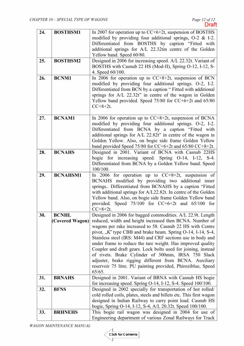
CHAPTER 10 – SPECIAL TYPE OF WAGONS
WAGON MAINTENANCE MANUAL
Page 12 of 12
24. BOSTHSM1 In 2007 for operation up to CC+6+2t, suspension of BOSTHS modified by providing four additional springs, O-2 & I-2. Differentiated from BOSTHS by caption “Fitted with additional springs for A/L 22.32tin centre of the Golden Yellow band. Speed 60/80.
25. BOSTHSM2 Designed in 2006 for increasing speed. A/L 22.32t. Variant of BOSTHS with Casnub 22 HS (Mod-II), Spring O-12, I-12, S-4. Speed 60/100.
26. BCNM1 In 2006 for operation up to CC+8+2t, suspension of BCN modified by providing four additional springs. O-2, I-2. Differentiated from BCN by a caption “ Fitted with additional springs for A/L 22.32t” in centre of the wagon in Golden Yellow band provided. Speed 75/80 for CC+6+2t and 65/80 CC+8+2t.
27. BCNAM1 In 2006 for operation up to CC+8+2t, suspension of BCNA modified by providing four additional springs. O-2, I-2. Differentiated from BCNA by a caption “Fitted with additional springs for A/L 22.82t” in centre of the wagon in Golden Yellow. Also, on bogie side frame Golden Yellow band provided Speed 75/80 for CC+6+2t and 65/80 CC+8+2t.
28. BCNAHS Designed in 2001. Variant of BCNA with Casnub 22HS bogie for increasing speed. Spring O-14, I-12, S-4. Differentiated from BCNA by a Golden Yellow band. Speed 100/100.
29. BCNAHSM1 In 2006 for operation up to CC+8+2t, suspension of BCNAHS modified by providing two additional inner springs.. Differentiated from BCNAHS by a caption “Fitted with additional springs for A/L22.82t. In centre of the Golden Yellow band. Also, on bogie side frame Golden Yellow band provided. Speed 75/100 for CC+6+2t and 65/100 for CC+8+2t.
30. BCNHL (Covered Wagon)
Designed in 2006 for bagged commodities. A/L 22.9t. Length reduced, width and height increased then BCNA. Number of wagons per rake increased to 58. Casnub 22 HS with Centre pivot, „K‟ type CBB and brake beam. Spring O-14, I-14, S-4, Stainless steel (IRS: M44) and CRF sections use in body and under frame to reduce the tare weight. Has improved quality Coupler and draft gears. Lock bolts used for joining, instead of rivets. Brake Cylinder of 300mm, IRSA 750 Slack adjuster, brake rigging different from BCNA. Auxiliary reservoir 75 litre. PU painting provided, Phiroziblue, Speed 65/65.
31. BRNAHS Designed in 2001. Variant of BRNA with Casnub HS bogie for increasing speed. Spring O-14, I-12, S-4. Speed 100/100.
32. BFNS Designed in 2002 specially for transportation of hot rolled/ cold rolled coils, plates, steels and billets etc. This first wagon designed in Indian Railway to carry point load. Casnub HS bogie, Spring O-14, I-12, S-4, A/L 20.32t. Speed 100/100.
33. BRHNEHS This bogie rail wagon was designed in 2004 for use of Engineering department of various Zonal Railways for Track
Draft

CHAPTER 10 – SPECIAL TYPE OF WAGONS
WAGON MAINTENANCE MANUAL
Page 13 of 12
Relaying Trains (TRT), specially for loading RCC sleepers, Axle Load 20.32t. Casnub 22 HS, Spring O-14, I-12, S-4. The design was provided with Transition CBC and air brake system. Speed 50/65.
34. BOBSNM1 In 2006 for operation at 25t A/L, suspension of BOBSN modified by providing four additional inner springs, Bogie renamed as Casnub 22 NLC, Speed 50/60.
35. BOBRM1 In 2006 for operation up to CC+6+ 2t, suspension of BOBR modified by providing four additional springs, O-2 & I-2. Differentiated from BOBR by a caption “Fitted with additional springs for A/L 22.32t in centre of wagon in Golden Yellow. Also, on bogie side frame Golden Yellow band provided. Speed 70/75.
36. BTPGLN Bogie liquefied petroleum gas tank wagon, tare 41.60t, CC 37.6 t, and Gross 79.20 t. The wagon is fitted with Air brake system, Casnub 22 NLB bogie, O-12, I-8, S-4. A/L20.32t. Speed 75/80.
37. BOXNHAM A variant of BOXNHA wagon achieved by conversion of BOXN type wagons during POH/Rebuilding. Axle Load: 22.82 t Bogie: IRF 108 HS, Spring O-14 & I-14, S-4. Conversion being done through operation of Railway Board RSPs. Cleared Speed at CC+8+2 t A/L of 100/100 Kmph.
38.
39.
40.
41.
Draft

Chapter 11 Infrastructural facilities for freight yard, sick line and ROH depots: Page 1 of 13
WAGON MAINTENANCE MANUAL
CHAPTER – 11
INFRASTRUCTURE FACILITIES
Draft

Chapter 11 Infrastructural facilities for freight yard, sick line and ROH depots: Page 2 of 13
WAGON MAINTENANCE MANUAL
CHAPTER – 11
INFRASTRUCTURE FACILITIES (For Freight yard, Sick line and ROH Depots)
1101 Introduction:
To achieve best performance of freight stock it is necessary that these stocks are maintained properly. The maintenance pattern and practices to be followed have been described in the previous chapters of this manual. However, despite of best practices and trained manpower, proper maintenance, availability and reliability of assets cannot be achieved if adequate infrastructure is not available. Accordingly, the Railway Board has laid great stress on review and improving availability of required infrastructural facilities for maintenance and vide their letter no. ERB – I/ 2006/ 26/ 46 dated 14.12.06 nominated an ED’s committee for rationalization of train examination points, sick lines and ROH depots. The criteria for categorization of examination/repair facilities recommended by the ED’s committee are as under (Ref: Bd’s letter no. 96/ M(N)/ 204/ Vol -I / II dated 09.03.04, 02.11.04 and 05.08.04)
A. Categorization of Examination / Repair facilities
I. Intensive Examination Points Category Criteria for Categorization
A
(i) Having pucca pathways on more than 50% of the lines nominated for examination. (ii) Sufficient illumination facilites 150 lux. (iii) Sufficient material handling facilities. (iv)Sufficient welding facilities.
B
(i) Having pucca pathways on more than 50% of the lines nominated for examination. (ii) Sufficient illumination facilities. (iii) Sufficient material handling facilities.
C
(i) Having pucca pathways on more than 50% of the lines nominated for examination. (ii) Sufficient illumination facilities.
D
(i) Having pucca pathways on more than 50% of the lines nominated for examination.
E No pucca pathway but some other facilities are available F No facilities available.
II. ROH Depots
Category Criteria for Categorization A Where all the infrastructural facilities are adequate. B Where all the infrastructural facilities are available but some not adequate
to match target out turn C Where some vital infrastructural facilities like EOT crane/wheel turning
lathe etc. are not available, other facilities are adequate. D Where facilities are grossly inadequate or non-existent.
Draft

Chapter 11 Infrastructural facilities for freight yard, sick line and ROH depots: Page 3 of 13
WAGON MAINTENANCE MANUAL
III. Sicklines Category Criteria for Categorization A (i)Berthing capacity under covered shed (ii) Heavy duty concrete flooring in working area. (iii) Availability of welding facility. (iv) Availability of Compressor/ Exhauster. (v) Availability of EOT crane B (i) Berthing capacity under covered shed. (ii) Heavy duty concrete flooring in working area. (iii) Availability of welding facility. (iv) Availability of Compressor/ Exhauster. (v) Synchronized whiting jacks. C (i) Berthing capacity under covered shed. (ii) Heavy duty concrete flooring in working area. (iii) Availability of welding facility. (iv) Hydraulic Jacks for lifting D (i) Berthing capacity under covered shed.
(ii) Heavy duty concrete flooring in working area. E Berthing capacity under covered shed. F Without any Berthing capacity under covered shed.
The details of infrastructural facilities required for examination yards, sicklines and ROH depots are described in subsequent paragraphs.
1102. INFRASTRUCTURE & FACILITIES REQUIRED IN THE YARD
i. Centre to centre distance between tracks for nominated lines for conducting intensive examination should be minimum 7.5 meters.
ii. Concrete pathways, material handling equipment, multi utility vehicle to facilitate movement of man and material smoothly from one end to other end.
iii. Proper illumination, specially covering bogies and brake gear locations so that the wagons needing attention can be easily detected.
iv. Welding grid on the entire length of train of nominated line with proper earthing arrangement so that welding can be carried out without marking the wagon sick.
v. Enough outlets for tapping air pressure for testing of the stock. vi. Duty room for Section Engineer/Junior Engineer (C&W), staff room, air
compressor room, store room for stocking material, tool room, welding machine room, battery charging room etc.
vii. VHF sets / CUG phones for close monitoring and communication between supervisors, staff and Sr. Section Engineer (In-charge).
viii. Portable LED type inspection lamps.
A. MACHINERY & PLANT ITEMS
The following machinery and plant are essential for train examination during yard maintenance:
Diesel and Electrically driven Compressor Welding plants Wagon /Rake Test rig
Draft

Chapter 11 Infrastructural facilities for freight yard, sick line and ROH depots: Page 4 of 13
WAGON MAINTENANCE MANUAL
Hydraulic jacks of various capacities. Lister truck for carrying material such as brake blocks etc. DG set (Cap. 200 kva min.) Multi utility vehicle for transportation of Men, Materials and Tools from
one end of rake to other. Gas/ Plasma cutting set .
B. TOOLS
Fitters should have the following tools.
Tool Bag Hammer Chisel Punch (Flat & Round End) LED head lamp Spanners of various sizes Pipe wrench Wheel tyre defect gauge Measuring foot rule Measuring tape Non contact hot axle detector Cord for measuring spring camber Gauge for measuring “A” dimension Test plate “GO /NO GO” gauges
To be made available in Section Engineer/Junior Engineer (C&W) office
All types of jacks Banner flag/Tail lamp CBC height gauge Air pressure gauge Chisel with wire handle Punch with wire handle Sledge hammer Scale – Steel rule 6” Measuring tape – 3 m Allen key (full set) Circlip plier (internal & external 19-60 mm) Hacksaw with blade 12” Set of non sparking tools (for yard handling tank wagon) LED head lamp Helmet Ladder with platform 10 ft. height
Draft

Chapter 11 Infrastructural facilities for freight yard, sick line and ROH depots: Page 5 of 13
WAGON MAINTENANCE MANUAL
1103 INFRASTRUCTURAL FACILITIES FOR FREIGHT EXAMINATION YARD WITH WORLD CLASS FACILITIES FOR DETECHMENT FREE YARD.
(Ref.: CAMTECH’s Report No.CAMTECH/2007/M/W/Infra/1.0 Nov. 2007)
i) The yard handling upto 10 rakes per day shall have two examination lines of 750 m each to facilitate creation of gap, one line for keeping sick wagons and one line for keeping fit wagons released from sickline. All the four lines should be under covered shed to facilitate all weather working.
ii) The complete area of examination yard shall be provided with abrasion resistance granolithic concrete flooring and ballast free embedded track to ease movement of vehicles and material handling equipments.
iii) Centre distance between the examination, sick and fit line shall be 7.5 m to ensure free movement of material handling equipments and minor attention.
iv) No OHE wiring over the examination lines/Sick yard line /fit wagon line which shall be dealt with EOT crane.
v) Top wiring at both the ends of the train examination line for dropping the rake and waiting for crew/loco after release.
vi) TXR shall be provided with Industrial type Personal Digital Assistant (PDA) having pre-fed check sheets for recalling defects and examination data.
vii) A dedicated engine for placement of rakes in examination line if the rake is received with electric locomotive.
viii) A rail cum road shunting vehicle with capacity to haul 30 empty wagons shall be used for creating gaps between wagons. The vehicle shall also be provided with compressor and rake test rig for air brake testing of formations.
ix) For yards handling upto 10 rakes per day, 7 EOT cranes of 30 tonnes lifting capacity, 30 mtrs. Span and 650 mtrs.travelling shall be provided. Each wagon shall be lifted with the help of EOT cranes by using specially designed slings for lifting from axle box.
x) Major Sickline with all Infrastructural facilities would remain attached and adjacent to freight examination yard.
xi) To expedite repairs in-situ, adequate number of material handling vehicles and multi utility vehicles shall be provided.
xii) The covered shed shall be provided with alternate rows of metal halide lamps and set of T-5 tube light fittings. The illumination around covered shed should be provided by high intensity tower lights.
xiii) Electric panel with junction box at a distance of 30 m shall be provided in between sick yard line and examination line.
xiv) Effective communication system preferably CUG mobile phones or walkie talkie sets shall be provided across teams.
xv) A comprehensive contract for day to day upkeep of the yard is recommended for major and mega yards. This contract should cover items like scrap lifting and bush cutting in the periphery of the yard.
xvi) A running contract for petty repairs pertaining to shed and floor of the yard including civil and electrical engineering works is also recommended. This contract will be monitored by field officer of Mechanical Department.
xvii) A running contract for maintenance of all major M&P such as EOT cranes, compressor, vehicles, welding sets, hydraulic jacks is also recommended.
Draft

Chapter 11 Infrastructural facilities for freight yard, sick line and ROH depots: Page 6 of 13
WAGON MAINTENANCE MANUAL
1104. INFRASTRUCTURAL FACILITIES IN AIR BRAKE ROH DEPOTS
Air brake depots have been classified based on the target capacity for ROH outturn/month as follows:
Category Targeted capacity for ROH (Average/month)
Super Depots Above 500
Mega Depots 250 to 500
Major Depots 125 to 250
Minor Depots Upto 125
A. RECOMMENDED LAYOUT
Analysis of sick marking of existing ROH depots on IR reveals that on an average each air brake wagon visits the depot thrice in 18 months, once for schedule ROH and twice for out of course repairs requiring lifting.
Therefore, an air brake depot meant for undertaking 250 ROHs/month needs to
tackle another 500 wagons/month out-of-course repairs requiring lifting. Thus the layout should be spacious enough to release about 25-30 wagons/day.
The ROH schedule should be completed within 24 hours including placement
and withdrawal time. Thus, if the depot has to undertake 250 ROHs/month the berthing capacity for ROH wagons on trestles should be 12 taking 20% margin for heavy repairs. Considering a mixed ROH outturn and the working length for BOXN as 15m & BCN/BTPN as 20 m, the length of the ROH depot works out as 100 m.
Casnub bogies require extensive repairs of bogie components. These bogies
need to be tackled on bogie manipulators to ensure down hand welding. All wearing surfaces need to be built up to original (new) sizes. Further, all modifications issued by RDSO need to be implemented to ensure adequate safety. The bogie section is required to supply 20 bogies/day for undertaking 250 ROHs/month apart from repairing bogies required for out-of -course repairs. For this purpose, adequate work stations need to be set in a cranage area of about 2500 sq.m. (including wheel lathe area).
Recommended layout of bogie and body repair section for a Major depot
undertaking 250 ROHs per month along with sick line work of out-of-course repairs is given on next page:
Draft

Chapter 11 Infrastructural facilities for freight yard, sick line and ROH depots: Page 7 of 13
WAGON MAINTENANCE MANUAL
Body repair section EOT 15t /5t EOT 15t/5t 25m
EOT 10t/3t EOT 10t/3t 25m Wheel lathe Bogie repair section
100 m
Further details of the model layout and its end view are given in the attached Fig. II-A. The above layout has to be supplemented with facilities for Stores, machine shop, smithy shop, air brake equipment overhauling sections, model room, compressor room, canteen, hostel, etc. which will largely depend on the existing layout.
Covered area under cranes i.e. cranage area for a fixed ROH outturn is a
function of placement/withdrawal and number of working shifts. The recommended cranage area for depots undertaking 250 to 500 ROHs per month is given below:
1. For ROH depots with sickline attention
250 ROHs/month + sick line repairs with double shift.
5000 sq. m including wheel lathe shed. 300 5600 sq. m. 350 6200 sq. m. 400 6800 sq. m. 450 7400 sq. m. 500 8000 sq. m. 2. For ROH depots WITHOUT Sick line attention
Depots undertaking only ROH workload and no out-of-course repairs can manage the outturn of 250 ROHs/month in about 3000 sq. m. cranage area working in double shifts.
Draft
Click for Contents

Chapter 11 Infrastructural facilities for freight yard, sick line and ROH depots: Page 8 of 13
WAGON MAINTENANCE MANUAL
B. MODEL LAYOUT FOR UNDERTAKING 250 ROHs/ MONTH
Running tracks for DVS(Sick) wagons
WHEEL LATHE
Lean-to-roof
100M
10t/3t EOT (2 Nos.) 15t/5t EOT (2 Nos.)
Fig. II-A
BOX
BCN
BCN
BOXN
BOXN
BOGIE REPAIR
SECTION
TRACKS
Lean-to-roof Lean-to-roof
1.6 3.2 2 3.2 3.2 2 3.2 1.6 5
25 M 25 M
Draft
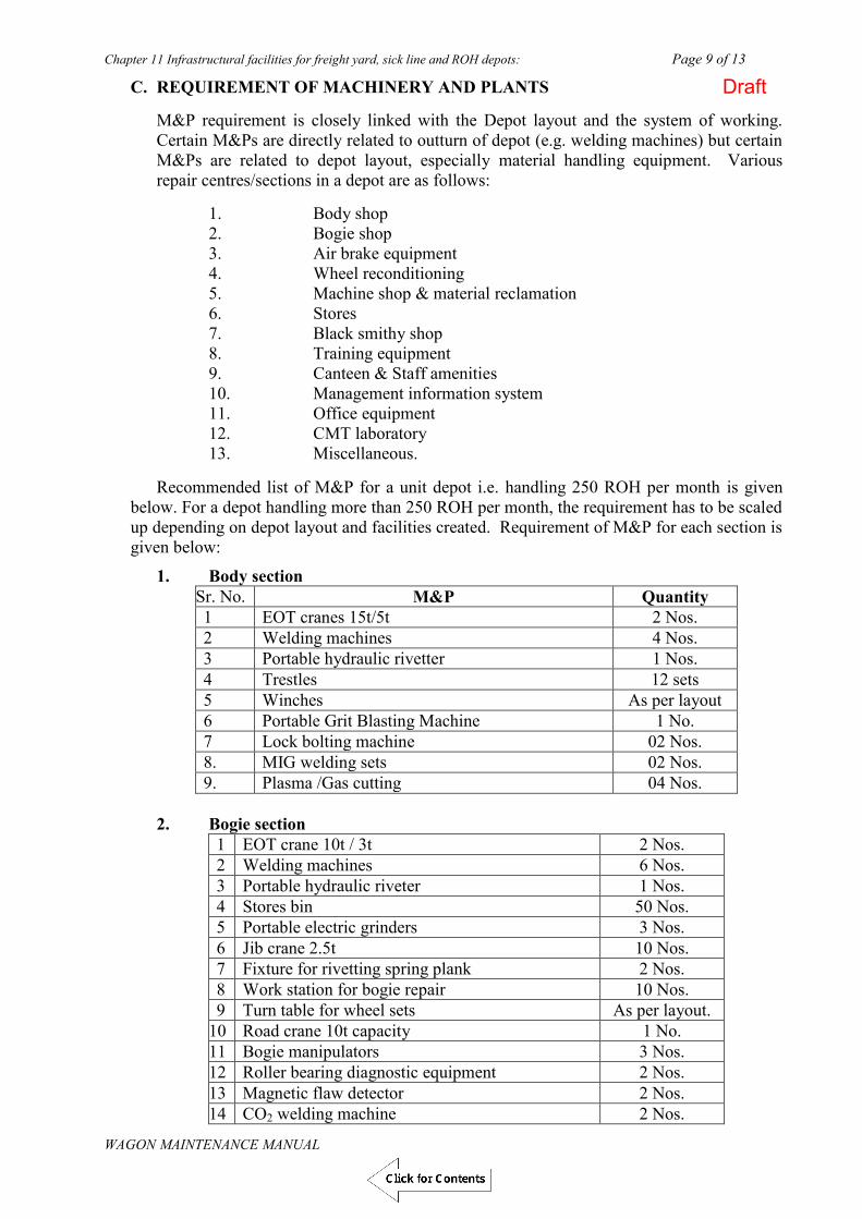
Chapter 11 Infrastructural facilities for freight yard, sick line and ROH depots: Page 9 of 13
WAGON MAINTENANCE MANUAL
C. REQUIREMENT OF MACHINERY AND PLANTS
M&P requirement is closely linked with the Depot layout and the system of working. Certain M&Ps are directly related to outturn of depot (e.g. welding machines) but certain M&Ps are related to depot layout, especially material handling equipment. Various repair centres/sections in a depot are as follows:
1. Body shop 2. Bogie shop 3. Air brake equipment 4. Wheel reconditioning 5. Machine shop & material reclamation 6. Stores 7. Black smithy shop 8. Training equipment 9. Canteen & Staff amenities 10. Management information system 11. Office equipment 12. CMT laboratory 13. Miscellaneous.
Recommended list of M&P for a unit depot i.e. handling 250 ROH per month is given below. For a depot handling more than 250 ROH per month, the requirement has to be scaled up depending on depot layout and facilities created. Requirement of M&P for each section is given below:
1. Body section Sr. No. M&P Quantity 1 EOT cranes 15t/5t 2 Nos. 2 Welding machines 4 Nos. 3 Portable hydraulic rivetter 1 Nos. 4 Trestles 12 sets 5 Winches As per layout 6 Portable Grit Blasting Machine 1 No. 7 Lock bolting machine 02 Nos. 8. MIG welding sets 02 Nos. 9. Plasma /Gas cutting 04 Nos.
2. Bogie section
1 EOT crane 10t / 3t 2 Nos. 2 Welding machines 6 Nos. 3 Portable hydraulic riveter 1 Nos. 4 Stores bin 50 Nos. 5 Portable electric grinders 3 Nos. 6 Jib crane 2.5t 10 Nos. 7 Fixture for rivetting spring plank 2 Nos. 8 Work station for bogie repair 10 Nos. 9 Turn table for wheel sets As per layout.
10 Road crane 10t capacity 1 No. 11 Bogie manipulators 3 Nos. 12 Roller bearing diagnostic equipment 2 Nos. 13 Magnetic flaw detector 2 Nos. 14 CO2 welding machine 2 Nos.
Draft

Chapter 11 Infrastructural facilities for freight yard, sick line and ROH depots: Page 10 of 13
WAGON MAINTENANCE MANUAL
3. Air brake equipment
1 Elec. Stationery screw air compressor completes with air receiver 15 m 3/min (This is for depot only. Additional compressors will be required for yard).
1 No.
2 Portable diesel compressor 1 No. 3 Single Wagon test rig 2 Nos. 4 DV test stand 1 No. 5 Hydraulic pipe bending machine 1 No. 6 Air conditioners with voltage stabilizer 2 Nos. 7 Torque wrench with various sizes of sockets less
than 1 inch. 4 set.
8 Ultrasonic cleaning table for DV components 1 Nos.
4. Wheel Reconditioning Equipment
1 Surface wheel lathe with Servo controlled voltage stabilizer
1 No.
2 Pneumatic torque wrench with sockets 1” to 2” 4 sets 3 Pressure grease drum with guns 15t capacity. 2 Nos. 4 Ultrasonic flaw detector 2 Nos. 5 Bearing marking gadget 1 set 6 Mono-rail for handling swarf (detail plan will
depend on layout) 1 set
7 Bins for storing bearings As per requirement
8 Fork lifter 2.5t 1 No. 9 P.C. Terminal 1 No. 10 Wheel diameter measuring gauge 2 Nos.
5. Machine shop & material reclamation
1 Heavy duty shaping machine 1 No. 2 Jib crane 2.5t 1 No. 3 Centre lathe 12 ½” cap. 1 No. 4 Redial drilling machine 1 No. 5 Centre lathe 6” cap 1 No. 6 Bench drilling machine 1 No. 7 Heavy duty pedestal grinder double ended 1 No. 8 Shearing machine 6 mm 1 No.
6. Stores
1 Truck 10t capacity 1 No. 2 Tractor with hydraulic lifting machine and 3
trolleys (trailers) 1 No.
3 Fork lift 2t 2 No. 4 Platform truck 2t 2 Nos. 5 Battery charger 2 No. 6 Weighing machine 500 kg 1 No. 7 Light store vehicle 1 No. 8 Hand trolleys with rubber wheels 10 Nos.
9 Storage racks As per layout
Draft

Chapter 11 Infrastructural facilities for freight yard, sick line and ROH depots: Page 11 of 13
WAGON MAINTENANCE MANUAL
10 Computer terminal with printer 1 No. 11 Furniture As per layout
7. Training equipment
1 Cut models of DV, SAB, Angle cock. 1 set (each) 2 Television /DVD player 1 set 3 Furniture As per reqt. 4 Hostel along with kitchen equipment As per
requirement 5 LCD projector 1 No. 6 PC 02 Nos.
8. Canteen & staff amenities
1 Water cooler 3 Nos. 2 Stainless steel tables & chairs As per reqt. 3 Kitchen equipment, cooking gas, utensils As per reqt. 4 Fitter’s lockers As per reqt.
9. Office Equipment
1 PC terminal As per reqt. 2 Printer As per reqt. 3 Furniture As per reqt. 4 Air conditioner & computer room. As per reqt. 5 Intercom 10 lines 1 No. 6 Fax with P&T line 1 No. 7 First aid equipment 4 set 8 Photocopier 1 No. 9 V.H.F. / CUG phones As per reqt.
10. Miscellaneous
1 Gas cutting equipment 4 Nos. 2 Hydraulic jacks As per reqt. 3 SAB test bench 1 No. 4 CBC and draft gear replacement equipment 2 sets 5 DG set 350/500 KVA 1 No. 6 Electric and pneumatic tools As per reqt. 7 Rivetting equipment As per reqt. 7 Fitter’s hand tools. As per reqt. 8 Gauges & instruments. As per reqt. 9 Wheel flat detector system (*) As per reqt.
(*) To be installed in depots/yards as per instructions of Railway Board. Note: Where power failures are rampant, a Diesel Generating Set to run the wheel lathe and cranes may also be planned.
Draft
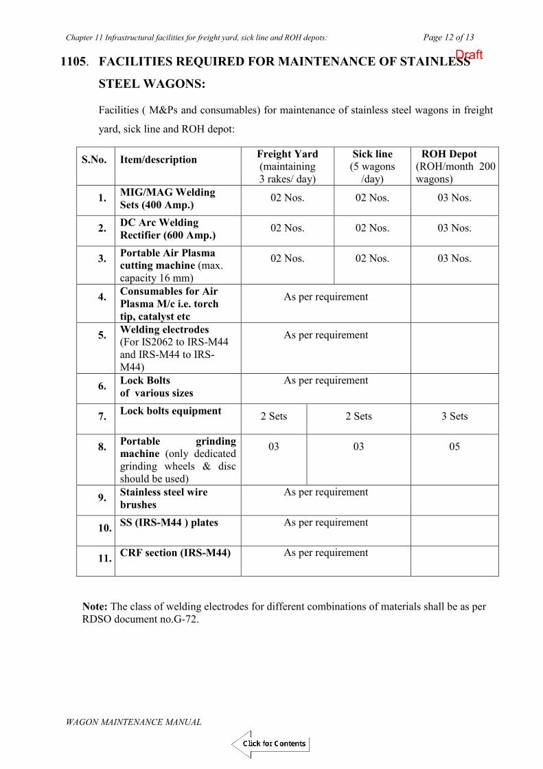
Chapter 11 Infrastructural facilities for freight yard, sick line and ROH depots: Page 12 of 13
WAGON MAINTENANCE MANUAL
1105. FACILITIES REQUIRED FOR MAINTENANCE OF STAINLESS
STEEL WAGONS:
Facilities ( M&Ps and consumables) for maintenance of stainless steel wagons in freight
yard, sick line and ROH depot:
S.No. Item/description Freight Yard (maintaining 3 rakes/ day)
Sick line (5 wagons
/day)
ROH Depot (ROH/month 200 wagons)
1. MIG/MAG Welding Sets (400 Amp.) 02 Nos. 02 Nos. 03 Nos.
2. DC Arc Welding Rectifier (600 Amp.) 02 Nos. 02 Nos. 03 Nos.
3. Portable Air Plasma cutting machine (max. capacity 16 mm)
02 Nos. 02 Nos. 03 Nos.
4. Consumables for Air Plasma M/c i.e. torch tip, catalyst etc
As per requirement
5. Welding electrodes (For IS2062 to IRS-M44 and IRS-M44 to IRS-M44)
As per requirement
6. Lock Bolts of various sizes
As per requirement
7. Lock bolts equipment 2 Sets 2 Sets 3 Sets
8. Portable grinding machine (only dedicated grinding wheels & disc should be used)
03 03 05
9. Stainless steel wire brushes
As per requirement
10. SS (IRS-M44 ) plates As per requirement
11. ` CRF section (IRS-M44) As per requirement
Note: The class of welding electrodes for different combinations of materials shall be as per RDSO document no.G-72.
Draft

Chapter 11 Infrastructural facilities for freight yard, sick line and ROH depots: Page 13 of 13
WAGON MAINTENANCE MANUAL
1106 MINIMUM INFRASTRUCTURE REQUIRED FOR PREMIUM & CC
EXAMINATION
The following infrastructural facilities are considered essential to carry out premium
examination in less than 03 hrs.
Dedicated two or more examination lines with pathways (depending upon nos. of
rakes examined)
Embedded track/ Pucca pathway of 02 m width as per layout
Welding facilities and Portable welding set
Adequate illumination
Pallets for material storage/dispensing
Road between office/store and examination yard
Connectivity with FOIS
Walkie Talkie sets
Provision of MUV (e.g.Tata Ace truck) for transportation of staff and
materials/equipments to examination point
Rechargeable LED head lamp
▄ ▄ ▄ ▄ ▄ ▄
Draft

APPENDIX- I Tippler Page 1 of 6
WAGON MAINTENANCE MANUAL
APPENDIX- I TIPPLER
1.0 Introduction
The tippler machines are used by private siding honours for tippling of BOX ‘N’ wagons loaded with coal. The loaded wagons are marshaled in the tippling line and placed on the tippling unit one by one for unloading. Types of tipplers: There are two types of tipplers being installed in the pvt. Sidings.
1. Side discharge tippler 2. Rotary type wagon tippler
2.0 General requirements
2.1 The design and construction of components of tipplers and auxiliary handling
equipment coming into contact with any part of wagon shall be such that no damage whatsoever is caused to the wagon equipment or its paint.
2.2 The top clamping pressure shall be such as will hold the wagons firmly in position on
rails and keep the running gear from getting dislodged without causing any deformation to the wagon structure.
2.3 Adequate compensating measures shall be taken in top clamps and side support beam
to compensate for manufacturing imperfections, within the permissible limits, in the top copings and side stanchions of the wagon, so that clamping pressure on the contacting area on the side and top of the wagon is uniformly distributed.
2.4 The side supports for tipplers shall meet the following requirements:
a) The side support shall consist of a longitudinal beam, which shall be as long as the longest wagon to be tippled. This beam shall be continuous.
b) The side support shall be articulated so that it can take the tapered as well as
parallel stanchions on the body of the wagons. Alternatively, the cradle shall be articulated on trunion to achieve this.
c) Full-face contact between the side support beam and the side stanchions shall be
ensured. The side supports shall extend from a height of 1000 mm up to 2950mm, from rail level, i.e. contact the side of the wagon over a width of not less than 1950mm. [For wagons of height less than 2950mm, typically iron ore wagons, (user shall have to consult the concerned zonal railway for this confirmation) suitable slots shall be provided in the side support beam, to permit the top clamping of the wagons] There shall be metal to metal contact between the side support beam and the side stanchions of the wagon i.e. no rubber pad or
Draft

APPENDIX- I Tippler Page 2 of 6
WAGON MAINTENANCE MANUAL
any other alternative, shall be provided on the contact face of the side support beam
d) The side support beam shall be moveable type, the movement being done by hydraulic arrangement. (No external or moveable counter weights should be used with the side support beam) Facility of forward/ backward movement should exist, such that it should be able to move & touch the wagon without applying any pressure on the wagon side-wall. At this position it should get locked and the tilting operation can begin. At the end of the tippling cycle, the side support should return to its home position, so that the next wagon can be positioned on the tippler Movement of the side support should be controlled & the speed should be crawling just before making contact with the wagon sidewall.
e) Pressure gauge/s should be mounted, at easily accessible location, for reading the hydraulic pressure of the side support hydraulic arrangement.
3.0 Safety requirements – Safety requirements for tipplers, divided into the following three stages, construction stage shall be followed as under:
3.1 Construction stage
a. The design of the tippler shall avoid, as far as possible, any spillage of the material
handled by the wagons. b. Devices shall be built-in to prevent any over run of the wagons in either direction. c. The tippler shall be designed so that the wagon is securely held in all operating
positions. d. Automatic devices shall be provided to hold the tipplers securely in any position in
the event of failure of the drive unit. e. All tipplers shall have means to limit the angle of tippling. f. Arrangement shall be made on tipplers to prevent feet being trapped between the
platform and the base of the tippler. g. Whenever possible mechanical or electrical devices shall be built-in to ensure that all
the conditions allowing wagon tipping are coordinated. h. Additionally, a device shall be provided to prevent an empty wagon from being
released until the tippler is back in original position. i. A device shall be provided to prevent the entry of a non-scheduled wagon into a
tippler. Sharp edges and corners in all working spaces shall be avoided. k. The parts projecting into working spaces shall be as small as possible.
Draft

APPENDIX- I Tippler Page 3 of 6
WAGON MAINTENANCE MANUAL
l. All the frequently used lubrication points shall be accessible without it being necessary to remove the guards.
m. It is recommended that equipment shall be so designed that maintenance and
cleaning is facilitated. n. Fully integrated controls should be provided for wagon positioning system, wagon
holding devices and wagon tippler. The controls should be interlocked so that there is no chance of accident due to error in sequence of operation.
4.0 Positioning system for wagon
Wagon tipplers shall be provided with side arm charger for positioning of wagons on the tipplers, such that
a. Side arm charger should be of sufficient capacity, depending on whether complete train or some wagons are to be moved / positioned. There should be some positive system for centering of wagon on the tippler table.
b. Drive unit for the side arm charger should be of positive type e.g. rack & pinion, so
that sudden jerks/slippages are avoided. Suitable technology should be used, so that the wagon can be moved at slow speeds for placement on tippler table e.g. Low speed hydraulic motors, Variable frequency AC motors or thyrister controlled DC motors (through epicyclical reduction gearing), etc.
c. Charger should be able to slow down to creeping speed just before the final
positioning
5.0 Wagon & Train holding devices 5.1 Wheel grippers a. These are mandatory & should be located on the tippler table, to prevent inadvertent
motion of the wagons during tippling operation. b. These should be so designed that balanced pressure is applied on both sides of the
wheel rim. It should have a floating arrangement so as to ensure that force on each gripper is same and should have some lateral float so that it can take a new position in case of variation in wheel gauge. Wheel grippers should be free from serrations or any such provision on its holding face. Wheel grippers should be made of soft material.
5.2 Retractable wheel chocks
a. These are mandatory & should be fitted at the in-haul & out –haul tracks, to prevent accidental rolling of the wagons on the tippler table.
Draft

APPENDIX- I Tippler Page 4 of 6
WAGON MAINTENANCE MANUAL
b. They should be so designed that flange of the wheel is not contacted while
blocking tread of the wheel. Shape of the chock should take into account the wheel incline, so that a line contact is made with the wheel.
6.0 Check sheet for joint inspection
Check sheet for the six monthly joint inspection of the tipplers to be conducted by DME/ Sr.DME (C&W) of the concerned division or his authorised representative and representative of the siding owner, as per Railway Board letter No.98/M(N)/951/12 dated 27.11.02, is as follows: SN
Item Check Remark
1 End frame platform
side beam
(i) (ii)
Steel work to be examined for damage or defects. Check & record the gap between the side beam and the wagon side stanchion, during tipping operation.
2 Drive gear (i) (ii)
Check proper matching of rack and pinion tooth & tooth wear . Check whether coupling gives jerk during rotation. The tippling operation should be smooth & without any jerks
3 Top hydraulic clamp (i) (ii) (iii) (iv) (v) (vi)
Check the level of clamp pad. Whether sitting properly or not. Check the condition & thickness of clamp pad (thickness should not be less than 50 mm) Check the smoothness of clamp movement Check for provision of indicators on the tippler table for all types of wagon stock, which are likely to be tippled on the tippler. This is to ensure that wagons are placed on the tippler table in such a manner that the top clamping pads position is near the side stanchions. Force exerted by the top clamps should not exceed 1.5t per clamp pad. Check & record the value. Check for provision of a wagon bogie spring relief mechanism in the top clamp locks for permitting release of bogie springs.
Draft

APPENDIX- I Tippler Page 5 of 6
WAGON MAINTENANCE MANUAL
4 Rail table of wagon tippler
(i) Check the level and alignment of rail. The level of track on tippler table and that of approach rails should be the same so that the wagons do not experience any jerk during in-haul and out-haul
5 Limit switches (i) Check for proper function 6 In haul & out haul
stop linkage
(i) (ii)
Check satisfactory working of stop Movement. Check the gradient on the outhaul side.
7 Side arm charger* (i) (ii) (iii) (iv) (v)
Check damage / defects of steel work. Check proper matching of drive pinion & rack & tooth wear. Check the smooth movement and final position of arm hoist. Check the proper tightening of fastener & condition of track. Check for proper functioning of limit switches & proximity switches
8 Damages to wagons. (i)
Damages during tippling & post tippling damages: Dents/nick on the side stanchions,
top copings, wagon body, etc Displacement of bogie pivot or
suspension springs Damages to air brake pipes Axle box adopter shifting Coupler damages
Any other
*Note: (1) There should not be any loose shunting of the wagons. In-haul and out-haul arrangements consisting of side arm charger should be used for placement and removal of wagon on tippler table. The practice of shunting empty wagon after tippling by rake of loaded wagons is not acceptable as it results into large scale damages to CBC and bogies. Representative of the Sr DME (C&W) /DME Siding owner or Authorised representative
Draft

APPENDIX- I Tippler Page 6 of 6
WAGON MAINTENANCE MANUAL
Draft

APPENDIX – II - LIST OF IMPORTANT MODIFICATIONS TO BE CARRIED OUT ON FREIGHT STOCK
WAGON MAINTENANCE MANUAL
Page 1 of 2
APPENDIX “II” LIST OF IMPORTANT MODIFICATIONS TO BE CARRIED OUT ON FREIGHT STOCK (IRCA letter No. M/129/Policy/W dated 12.4.99 & Rly Bd. L. No. 98/M(N)/951/11 dt.6.4.99) I. WHEELS, AXLES, BEARINGS
1. Adoption of worn wheel profile for all BG wheels
MW/CWSC/58 dt.18.3.92
YES YES YES YES
2. Additional Intermediate Profile for wagon wheel.
RDSO letter no. MW/WA/GENL. Dated 13/15.01.2010
----- Yes Yes -----
3. Stamping of Overhauling date of CTRB on Backing Ring
RDSO letter no. MW/WA/GENL Dated 26.04.2012
----- ---- Yes -----
4. Non Use of Seal Wears Rings with vent holes
1. RDSO letter no. MW.RB.GENL. Dated 15/18.06.2012
2. RDSO letter no. MW/RB/BOXN Dated 08/12.08.2002
----- ---- Yes -----
5. Non Use of Backing Rings with Vent holes
1. RDSO letter no. MW/RB/BOXN Dated 20.12.1993
2. RDSO letter no. MW/RB/BOXN Dated 02.06.1995
----- ----- Yes -----
6. Phasing out of wheels having Sprag Holes from freight stock.
Railway Board’s letter no. 2000/M (N)/960/1/Pt Dated 03.09.2008
-----
Yes
Yes
-----
II. WAGON SUPER STRUCTURE AND BRAKE RIGGING
1. Strengthening of horizontal lever support (large on BOXN/BCNA wagons)
MW/BOXN/MAINT/dt.24.1.94
NO YES YES YES
2. Provision of anti rotation lug on empty tie rod coupling nut of BOXN/BCN wagons
MW/BOXN/MAINT/dt.15.1.94
YES YES YES YES
3. Provision of stiffener angle on axle guard of BVZC wagon
MW/CWSC/Secretariat dt. 23.11.93 & 28.2.94
NO NO YES YES
4. Increase in the diameter of control rod from 28 to 32 mm of IRSA-600 Slack Adjuster
MW/SLA dt 23/29.12.93 & 10.5.94
NO YES YES YES
5. Provision of side bracket with link on BRH/BRN wagons to facilitate securing of steel plant consignment to wagon body
MW/ACT/BG dt. 27.5.94
NO YES YES YES
6. Modification to empty/load spindle bracket
MW/BTPN dt. 1.11.94 NO NO YES YES
7. Provision of extra roller type pull rod supports as per drg. WD-90016-S/1 Alt 12
NO YES YES Not under
manufacture
Draft

APPENDIX – II - LIST OF IMPORTANT MODIFICATIONS TO BE CARRIED OUT ON FREIGHT STOCK
WAGON MAINTENANCE MANUAL
Page 2 of 2
8. Underframe strengthening of all welded BRN wagons
MW/BRN dt 12.12.98 NO NO YES Not under
manufacture
9. Modification of existing door hold stiffener of BOBRN
MW/DOM/BOBR dt. 14.6.90
NO YES YES YES
10. Modification to anchoring tee joint on BTPN wagons
MW/BTPN dt.24/26.8.98
NO NO YES NA
III. COUPLER & DRAFT GEARS
1. Fitment of modified striker casting wear plate in CBC
MW/CPL/BG/HT dt.6.1.88
NO NO YES YES
IV. AIR BRAKE SYSTEM
1. Standardisation of isolating handle cock on DV
MW/APB/TP/M dt.27.9.88
NO YES YES YES
2. Modification to filtering arrangement of C3W DV of SCL
MW/APB/TP/M dt.24.11.88
NO YES YES YES
3. Provision of additional APD to DV MW/APB/TP/M dt.1/6-5-92
NO YES YES YES
4. Modification to quick release valve of DV of Escorts make
MW/APB/TP/M dt.3/9-7-92
NO YES YES YES
5. Strengthening of APD for DV MW/APB/TP/M dt.15.7.92
NO NO YES YES
6. Modification to the piping of BVZC wagon for fitment of quick coupling and detachable pressure gauge
MW/APB/TP/M dt.3/6-12-93
NO YES YES YES
7. Modification to hose coupling support
MW/APB 8/10-4-94 NO YES YES YES
8. Modification to the locking arrangement of barrel with leader nut casing of DRV2-600
MW/SLA dt. 20/21-7-88
NO YES YES YES
Draft
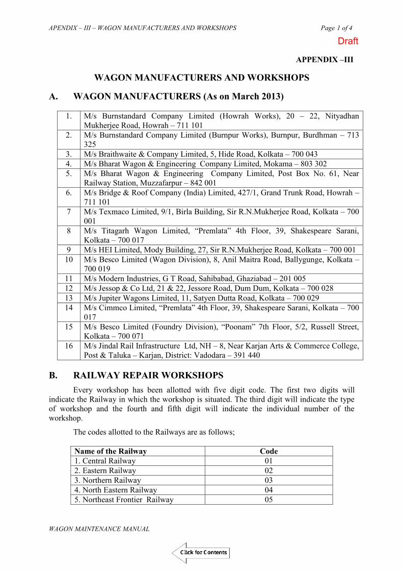
APENDIX – III – WAGON MANUFACTURERS AND WORKSHOPS Page 1 of 4
WAGON MAINTENANCE MANUAL
APPENDIX –III
WAGON MANUFACTURERS AND WORKSHOPS A. WAGON MANUFACTURERS (As on March 2013)
1. M/s Burnstandard Company Limited (Howrah Works), 20 – 22, Nityadhan Mukherjee Road, Howrah – 711 101
2. M/s Burnstandard Company Limited (Burnpur Works), Burnpur, Burdhman – 713 325
3. M/s Braithwaite & Company Limited, 5, Hide Road, Kolkata – 700 043 4. M/s Bharat Wagon & Engineering Company Limited, Mokama – 803 302 5. M/s Bharat Wagon & Engineering Company Limited, Post Box No. 61, Near
Railway Station, Muzzafarpur – 842 001 6. M/s Bridge & Roof Company (India) Limited, 427/1, Grand Trunk Road, Howrah –
711 101 7 M/s Texmaco Limited, 9/1, Birla Building, Sir R.N.Mukherjee Road, Kolkata – 700
001 8 M/s Titagarh Wagon Limited, “Premlata” 4th Floor, 39, Shakespeare Sarani,
Kolkata – 700 017 9 M/s HEI Limited, Mody Building, 27, Sir R.N.Mukherjee Road, Kolkata – 700 001 10 M/s Besco Limited (Wagon Division), 8, Anil Maitra Road, Ballygunge, Kolkata –
700 019 11 M/s Modern Industries, G T Road, Sahibabad, Ghaziabad – 201 005 12 M/s Jessop & Co Ltd, 21 & 22, Jessore Road, Dum Dum, Kolkata – 700 028 13 M/s Jupiter Wagons Limited, 11, Satyen Dutta Road, Kolkata – 700 029 14 M/s Cimmco Limited, “Premlata” 4th Floor, 39, Shakespeare Sarani, Kolkata – 700
017 15 M/s Besco Limited (Foundry Division), “Poonam” 7th Floor, 5/2, Russell Street,
Kolkata – 700 071 16 M/s Jindal Rail Infrastructure Ltd, NH – 8, Near Karjan Arts & Commerce College,
Post & Taluka – Karjan, District: Vadodara – 391 440 B. RAILWAY REPAIR WORKSHOPS
Every workshop has been allotted with five digit code. The first two digits will indicate the Railway in which the workshop is situated. The third digit will indicate the type of workshop and the fourth and fifth digit will indicate the individual number of the workshop.
The codes allotted to the Railways are as follows;
Name of the Railway Code 1. Central Railway 01 2. Eastern Railway 02 3. Northern Railway 03 4. North Eastern Railway 04 5. Northeast Frontier Railway 05
Draft
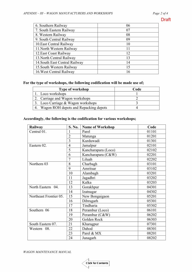
APENDIX – III – WAGON MANUFACTURERS AND WORKSHOPS Page 2 of 4
WAGON MAINTENANCE MANUAL
6. Southern Railway 06 7. South Eastern Railway 07 8. Western Railway 08 9. South Central Railway 09 10.East Central Railway 10 11.North Western Railway 11 12.East Coast Railway 12 13.North Central Railway 13 14.South East Central Railway 14 15.South Western Railway 15 16.West Central Railway 16
For the type of workshops, the following codification will be made use of;
Type of workshop Code 1. Loco workshops 1 2. Carriage and Wagon workshops 2 3. Loco Carriage & Wagon workshops 3 4. Wagon ROH depots and Repacking depots 4
Accordingly, the following is the codification for various workshops;
Railway S. No. Name of Workshop Code Central 01. 1 Parel 01101
2 Matunga 01201 3 Kurduwadi 01301
Eastern 02. 4 Jamalpur 02101 5 Kancharapara (Loco) 02102 6 Kancharapara (C&W) 02201 7 Liluah 02202
Northern 03 8 Charbagh 03101 9 Amritsar 03102 10 Alambagh 03201 11 Jagadhri 03202 12 Kalka 03203
North Eastern 04. 13 Gorakhpur 04301 14 Izatnagar 04302
Northeast Frontier 05.
15 New Bongaigaon 05201 16 Dibrugarh 05301 17 Tindharia 05302
Southern 06 18 Perambur (Loco) 06101 19 Perambur (C&W) 06202 20 Golden Rock 06303
South Eastern 07. 21 Kharagpur 07301 Western 08. 22 Dahod 08301
23 Parel & MX 08201 24 Junagarh 08202
Draft
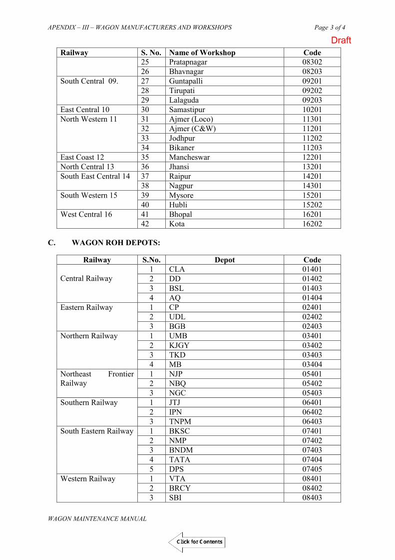
APENDIX – III – WAGON MANUFACTURERS AND WORKSHOPS Page 3 of 4
WAGON MAINTENANCE MANUAL
Railway S. No. Name of Workshop Code 25 Pratapnagar 08302 26 Bhavnagar 08203
South Central 09. 27 Guntapalli 09201 28 Tirupati 09202 29 Lalaguda 09203
East Central 10 30 Samastipur 10201 North Western 11 31 Ajmer (Loco) 11301
32 Ajmer (C&W) 11201 33 Jodhpur 11202 34 Bikaner 11203
East Coast 12 35 Mancheswar 12201 North Central 13 36 Jhansi 13201 South East Central 14 37 Raipur 14201
38 Nagpur 14301 South Western 15 39 Mysore 15201
40 Hubli 15202 West Central 16 41 Bhopal 16201
42 Kota 16202
C. WAGON ROH DEPOTS:
Railway S.No. Depot Code Central Railway
1 CLA 01401 2 DD 01402 3 BSL 01403 4 AQ 01404
Eastern Railway 1 CP 02401 2 UDL 02402 3 BGB 02403
Northern Railway 1 UMB 03401 2 KJGY 03402 3 TKD 03403 4 MB 03404
Northeast Frontier Railway
1 NJP 05401 2 NBQ 05402 3 NGC 05403
Southern Railway 1 JTJ 06401 2 IPN 06402 3 TNPM 06403
South Eastern Railway 1 BKSC 07401 2 NMP 07402 3 BNDM 07403 4 TATA 07404 5 DPS 07405
Western Railway 1 VTA 08401 2 BRCY 08402 3 SBI 08403
Draft
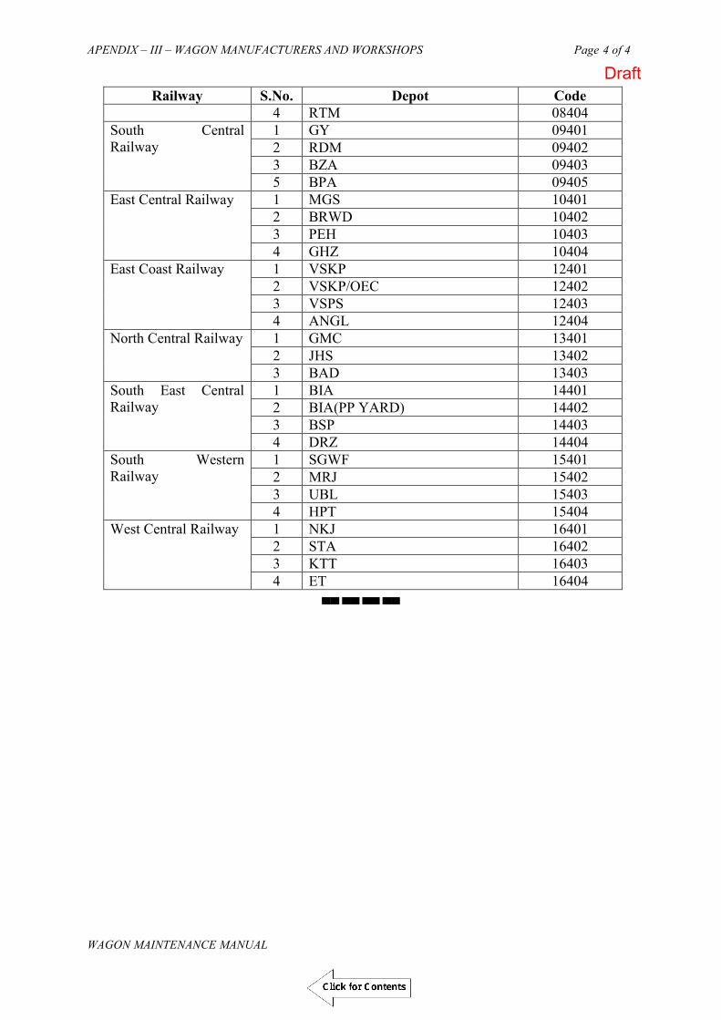
APENDIX – III – WAGON MANUFACTURERS AND WORKSHOPS Page 4 of 4
WAGON MAINTENANCE MANUAL
Railway S.No. Depot Code 4 RTM 08404
South Central Railway
1 GY 09401 2 RDM 09402 3 BZA 09403 5 BPA 09405
East Central Railway 1 MGS 10401 2 BRWD 10402 3 PEH 10403 4 GHZ 10404
East Coast Railway 1 VSKP 12401 2 VSKP/OEC 12402 3 VSPS 12403 4 ANGL 12404
North Central Railway 1 GMC 13401 2 JHS 13402 3 BAD 13403
South East Central Railway
1 BIA 14401 2 BIA(PP YARD) 14402 3 BSP 14403 4 DRZ 14404
South Western Railway
1 SGWF 15401 2 MRJ 15402 3 UBL 15403 4 HPT 15404
West Central Railway 1 NKJ 16401 2 STA 16402 3 KTT 16403 4 ET 16404
▄▄ ▄▄ ▄▄ ▄▄
Draft

APPENDIX IV- Branding Details on Wheel and Axle 1
WAGON MAINTENANCE MANUAL
APPENDIX IV BRANDING DETAILS ON WHEEL AND AXLE
Draft

APPENDIX – V List of Must Change Items in freight Stock during POH & IOH Page 1 of 5
WAGON MAINTENANCE MANUAL
APPENDIX - V
LIST OF MUST CHANGE ITEMS IN FREIGHT STOCK DURING POH AND ROH
(Railway Board’s Letter No. 2003/M(N)/951/22 dated 16-101-2013) ITEMS TO BE REPLACED DURING ROH
Sr. No. Description of item Justification for replacement
A CASNUB BOGIE
A-1 SF Key nut bolt with washer
During dismantling of wheel from bogie, it is necessary to cut the bolt since it is tack welded with nut. Therefore the committee recommends 100% replacement of this item during ROH.
A-2 Split Pin 12 x 110 mm
The split pins of Brake Shoe key are being changed 100% in some depots as they are getting distorted /damaged while taking out the brake blocks. Hence 100 % replacement is recommended during ROH.
A-3
CTRB Locking plate
The Locking plates are being changed on 100% basis. While carrying out the UST of Wheel sets, the locking plates are to be removed and while doing so, tabs are getting damaged or broken. Hence 100 % replacement is recommended during ROH.
B CBC
B-1 Striker casting Wear Plate
This item is subjected to wear in service as it comes in contact with CBC Shank. Wear Plate. Some ROH depots are replacing the item to the extent of 100 %. The worn out component will have serious impact on uncoupling of CBCs and it will also damage CBC shank; it will cause ovality on the top portion of Yoke Pin hole. Therefore the committee recommends 100% replacement of this item during ROH.
C Air Brake System
C-l
Dirt Collector Filter
This is basically a non-metallic strainer and of a small value. At present depots are changing on condition basis and there is an apprehension that dirt collectors are not at all opened in depots during ROH. There are many cases of DV malfunctioning and subsequent brake bindings in service and the filter is playing a major role. Therefore the committee recommends 100% replacement of this item during ROH so that it will be compulsory on the part of the depot to open the Dirt Collector.
Draft

APPENDIX – V List of Must Change Items in freight Stock during POH & IOH Page 2 of 5
WAGON MAINTENANCE MANUAL
C-2 Dirt Collector Washer ('O' Ring)
These are the small value rubber items perishable in nature and getting damaged while opening the assemblies. Therefore the committee recommends 100% replacement of this item during ROH.
C-3 Rubber gaskets C-4 MU washers C-5 AR Drain Plug leather
washer These items are perishable in nature getting damaged while opening the assemblies. Therefore the committee recommends 100% replacement of this item during ROH
C-6 BC Drain Plug leather washer
D Tank wagons D-1 Filling Pipe Joint Ring
(BTPN) These are the rubber items perishable in nature and getting damaged while opening the assemblies. Therefore the committee recommends 100% replacement of this item during ROH.
D-2 Man Hole Cover Sealing Ring.
ITEMS TO BE REPLACED DURING POH: Sr. No. Description of item Justification for replacement
A CASNUB BOGIE A-I Side Frame
l. Pedestal Jaw Liners
These items are subjected to wear in service as they are continuously in contact with adaptor and not expected to last beyond one POH. The liners of suitable thickness are Required to be welded. Therefore the committee recommends 100% replacement of these items during POH. Committee also recommends that no weld metal deposit should be done on the pedestal jaw surfaces to maintain the clearances as no machining is done after welding. RDSO may explore the possibility of liners in original design. The smoothness of the surface is primarily important.
2. SF Key nut bolt with washer
During dismantling of wheel from bogie, it is necessary to cut the bolt since it is tack welded with nut. Therefore the committee recommends 100% replacement of this item during POH.
A-2 Bolster 1 Land surface liner These items are subjected to wear in service as they are
continuously in contact with adaptor and expected to last from POH to POH. The liners of suitable thickness are required to be welded. Therefore the committee recommends 100% replacement of this item during POH.
2 Pocket slope liner
3. Rotation stop lug liner
Draft

APPENDIX – V List of Must Change Items in freight Stock during POH & IOH Page 3 of 5
WAGON MAINTENANCE MANUAL
A-3 Bogie Brake Gear
1
Split Pin 12 x 110 mm
The split pins of Brake Shoe key are being changed 100% in some depots as they are getting distorted/ damaged while taking out the brake blocks. Hence 100 % replacement is recommended during POH.
A-4 CTRB Locking plate
The Locking plates are being changed on 100% basis. While carrying out UST of the Wheel sets, the locking plates are to be removed and while doing so, tabs are getting damaged or broken. Hence 100 % replacement is recommended during POH.
A-5
Elastomeric pads
It has been observed that many workshops are replacing this item to the extent of 100%. Being a rubber component, committee recommends 100% replacement of this item during POH. However, the serviceable EM Pads shall be given to divisions for replacement during the course of train examination.
B Draw and Buffing Gear Assembly
B-1 Knuckle
Knuckle is subjected to wear on Nose, Pulling lug area. Some workshops are changing on 100% basis and released serviceable material is given to divisions. Knuckles are playing very important role in coupling gear. In the present spurt of train parting I uncoupling cases Knuckles might be playing a vital role. Upgraded couplers are being developed by RDSO as per WD70-BD-10. The committee therefore recommends one time replacement of indigenous knuckles with the upgraded knuckles as per WD- 70-BD-10. However, serviceable knuckles shall be given to divisions for replacement during train examination.
B-2
CBC Lock
Lock is subjected to wear on contact area corresponding to Knuckle pulling lug and curved surface. Committee has observed that majority of the uncoupling cases are on account of worn out Locks. Upgraded couplers are being developed by RDSO as per WD-70-BD-10.The committee therefore recommends one time replacement of indigenous CBC locks with the upgraded CBC locks as per WD- 70-BD-10. However, serviceable locks shall be given to divisions for replacement during train examination.
Draft

APPENDIX – V List of Must Change Items in freight Stock during POH & IOH Page 4 of 5
WAGON MAINTENANCE MANUAL
B-3
Rotary Lock Lift Assembly
Mostly, the Anti-Creep Lug of Lock Lifter Assembly is found in worn condition. Moreover, the alignment is disturbed due to riveting became loose in service Upgraded couplers are being developed by RDSO as per WD-70-BD-10. The committee therefore recommends one time replacement of indigenous lock lift assembly with the upgraded lock lift assembly as per WD-70:BD-l0. However, serviceable assemblies shall be given to divisions for replacement during train examination.
B-4 Bearing Piece
The committee observed that consumption of this item between workshops to workshop varies from 3% to 33%. The item is subjected to wear in service; the slot (17.5 mm x 17.5 mm) of bearing piece becomes worn out in service and not holding the Operating Handle in position. As a result the operating handle along with Rotary Lock Lift Assembly gets displaced from its position thereby causing uncoupling of CBC. The item is not expected to last beyond one POH. The committee therefore recommends 100% replacement of this item. However, serviceable bearing pieces shall be given to divisions for replacement during train examination.
B-5 Yoke Pin support plate liner
This item is subjected to wear particularly due to interaction of Yoke Pin's vertical movement. The pin makes a dent mark on the liner which is dangerous which restricts the movement of the yoke pin resulting in the breakage of Support plate rivets. The item is not expected to last beyond one POH cycle. The committee therefore recommends 100% replacement of this item.
B-6 Shank Wear Plate
This item is subjected to wear in service as it comes in contact with CBC Shank Wear Plate. Some workshops are replacing the item to the extent of 70%. The worn out component will have serious impact on uncoupling of CBCs and it will also damage CBC shank. The life of the component is not expected beyond one POH cycle. Therefore the committee recommends 100% replacement of this item during POH.
B-7 Striker Casting Wear Plate
This item is subjected to wear in service as it comes in contact with CBC Shank. Some workshops are already replacing the item to the extent of 100%. The worn out component will have serious impact on uncoupling of CBCs. The life of the component is not expected beyond one POH cycle. Therefore the committee recommends 100% replacement of this item during POH.
Draft
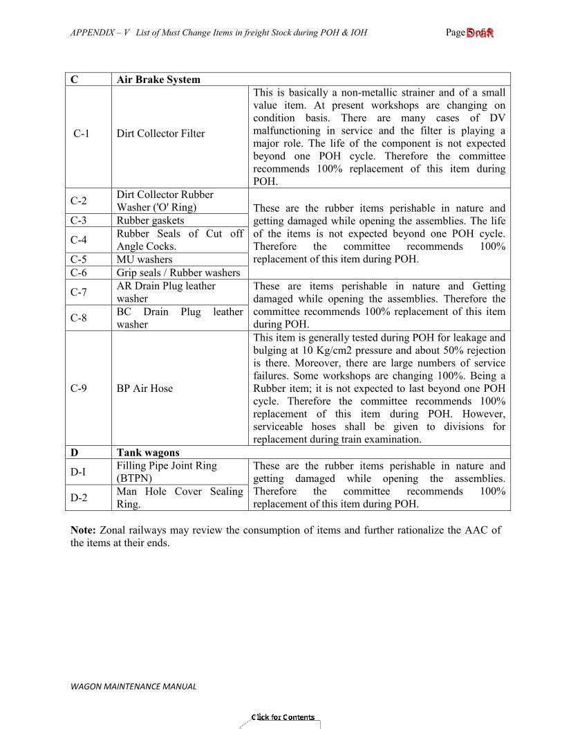
APPENDIX – V List of Must Change Items in freight Stock during POH & IOH Page 5 of 5
WAGON MAINTENANCE MANUAL
C Air Brake System
C-1
Dirt Collector Filter
This is basically a non-metallic strainer and of a small value item. At present workshops are changing on condition basis. There are many cases of DV malfunctioning in service and the filter is playing a major role. The life of the component is not expected beyond one POH cycle. Therefore the committee recommends 100% replacement of this item during POH.
C-2 Dirt Collector Rubber Washer ('O' Ring) These are the rubber items perishable in nature and
getting damaged while opening the assemblies. The life of the items is not expected beyond one POH cycle. Therefore the committee recommends 100% replacement of this item during POH.
C-3 Rubber gaskets
C-4 Rubber Seals of Cut off Angle Cocks.
C-5 MU washers C-6 Grip seals / Rubber washers
C-7 AR Drain Plug leather washer
These are items perishable in nature and Getting damaged while opening the assemblies. Therefore the committee recommends 100% replacement of this item during POH. C-8 BC Drain Plug leather
washer
C-9 BP Air Hose
This item is generally tested during POH for leakage and bulging at 10 Kg/cm2 pressure and about 50% rejection is there. Moreover, there are large numbers of service failures. Some workshops are changing 100%. Being a Rubber item; it is not expected to last beyond one POH cycle. Therefore the committee recommends 100% replacement of this item during POH. However, serviceable hoses shall be given to divisions for replacement during train examination.
D Tank wagons
D-I Filling Pipe Joint Ring (BTPN)
These are the rubber items perishable in nature and getting damaged while opening the assemblies. Therefore the committee recommends 100% replacement of this item during POH. D-2 Man Hole Cover Sealing
Ring. Note: Zonal railways may review the consumption of items and further rationalize the AAC of the items at their ends.
Draft

APPENDIX-VI-GUIDELINES FOR MAINTENANCE & Page 1 of 14 REPAIR OF STAINLESS STEEL WAGONS
APPENDIX “VI”
GUIDELINES
FOR
MAINTENANCE & REPAIR
OF
STAINLESS STEEL WAGONS
Draft

APPENDIX-VI-GUIDELINES FOR MAINTENANCE & Page 2 of 14 REPAIR OF STAINLESS STEEL WAGONS
WAGON MAINTENANCE MANUAL
GUIDELINESFOR
MAINTENANCE & REPAIR OF STAINLESS STEEL WAGONS
CONTENTS
1. Introduction-: ................................................................................................................. 3
2. Stainless Steel : The peculiarities:................................................................................. 3
3. Maintenance of SS Wagons : An Overview................................................................... 4
4. Facilities required for maintenance of Stainless steel Wagons:-................................ 4
5. MAINTENANCE ACTIVITIES IN SS WAGONS. ................................................... 5
5.1 Inspection
5.2 Cutting
5.3 Straightening
5.4 Replacement
5.5 Welding
6. SURFACE PREPARATION & PAINTING ............................................................. 13
Draft

APPENDIX-VI-GUIDELINES FOR MAINTENANCE & Page 3 of 14 REPAIR OF STAINLESS STEEL WAGONS
WAGON MAINTENANCE MANUAL
1. INTRODUCTION-:
Corrosion, is perhaps, the single biggest challenge, that needs to be surmounted, to attain increased service life of Wagons. Continuous exposure to moisture, air & high temperature, repair practices resulting in localized heating, loading/ unloading practices resulting in damages to the employed surface protection& incorrect/ inadequate surface protection are the main causes of propagation of corrosion.
An effective means of tackling corrosion, is by selecting corrosion-resistant raw material for fabrication of wagons. Such a selection, however, has, to consider, weldability, ease of fabrication, formability & availability of the chosen raw material besides the cost. Based on the above considerations, IR has introduced the use of Ferritic grade Stainless Steel (SS), to IRSM:44 specification, in BOXNHL & BCNHL wagons. Based on the experiences gained, IRSM:44, has also been introduced in rehab of BOXN wagons- BOXNR wagons.
The introduction of SS, has brought forth maintenance issues, related to cutting, welding or straightening of SS, patch repairs, attention to various types of similar and dissimilar joints between stainless steel, carbon steel and corten steel.
To understand, these maintenance issues, it is important to understand the inherent properties of SS & how it is different than the conventional MS, used hither-to in wagon fabrication.
2. STAINLESS STEEL: THE PECULIARITIES:
The chemistry of Stainless steel differs from carbon steel by the amount of chromium present. The presence of Cr, promotes the development of an invisible, adherent and self-healing chromium-rich oxide surface film. Carbon steel rusts when exposed to air and moisture. This rust, essentially an iron oxide film is active and accelerates corrosion by forming more iron oxide. Stainless steels have sufficient amount of chromium present so that a passive film of chromium oxide forms on initial oxidation, which prevents further corrosion.
The tough chromium-oxide layer, also comes into play, during the repair/ cutting of SS. In conventional carbon steels, during, oxy-cutting the metal is first heated by the flame, and then an excess of oxygen is supplied. This causes an exothermic (heat generation) reaction which generates the heat necessary to melt the oxides formed, which are then removed from the cut by the velocity of the gas jet. In this process a rough surface is produced. Where as, stainless steels having a high level of Chromium (Cr) cannot be cut by simple oxy-cutting methods due to the refractory nature (very high melting point) of the Chrome Oxide which is formed as the top layer.Ferritic stainless steels are generally limited to service temperatures below 750°F (400°C) due to the formation of embrittling phases, which may also precipitate during welding. Primary concerns with welding ferritic grades are maintaining adequate toughness and ductility in the as-welded condition.
Draft

APPENDIX-VI-GUIDELINES FOR MAINTENANCE & Page 4 of 14 REPAIR OF STAINLESS STEEL WAGONS
WAGON MAINTENANCE MANUAL
3. MAINTENANCE OF SS WAGONS : AN OVERVIEW
RDSO has introduced SS in the newly designed BOXNHL, BOXNLW, BOXNR & BCNHL wagons.
In constructional design, BOXNHL, BOXNR and BOXNLW wagon are similar to BOXN wagon and BCNHL wagon is similar to BCNA wagon. Hence, the maintenance and Repair procedure of these wagons shall be similar to BOXN/BCNA wagons. The procedure for attending to repairs in BOXN & BCNA are given in the Maintenance manual for Wagons Issued by CAMTECH.
However, since the wagon body and under frame of BOXNHL, BOXNLW, BOXNR & BCNHL wagons are made of higher grade steel i.e. IRSM-44 /IRS M-41 steel/CRF sections, the cutting, straightening, welding / repairing procedures are slightly different than plain carbon steel wagons.
Before elaborating on repair details, it is important to understand that the SS wagon structural members, body panels& other components that form part of the wagon structure, when corroded/damaged, should necessarily be repaired or replaced with similar grade of steel only.
4. FACILITIES REQUIRED FOR MAINTENANCE OF STAINLESS STEEL WAGONS:-
Reiterated below, for guidance, are recommended facilities (by CAMTECH) for effective maintenance of SS wagons:
S.No. Item/Description
Freight Yard
(maintaining 3 rakes/day)
Sick line
(5 wagon/day)
ROH Depot./workshops
(200 wagons/month)
1. MIG/MAG Welding sets (400 Amp.)
02 Nos. 02 Nos. 03 Nos.
2. DC Arc Welding Rectifier (600 Amp.)
02 Nos. 02 Nos. 03 Nos.
3. Portable Air plasma cutting machine (Max. capacity 16 mm)
02 Nos. 02 Nos. 03 Nos.
4. Consumables for Air Plasma M/C i.e. Torch tip, catalyst etc.
As per Requirement
5. Welding electrodes
For IRS M-44 to IRS M-41 etc.
As per Requirement
Draft

APPENDIX-VI-GUIDELINES FOR MAINTENANCE & Page 5 of 14 REPAIR OF STAINLESS STEEL WAGONS
WAGON MAINTENANCE MANUAL
6. Lock bolts of various sizes ( 3/8” to 7/8”)
As per Requirement
7. Lock bolting Equipment 02 sets 02 sets 03 sets.
8. Portable grinding Machine (only dedicated grinding wheels & disc should be used.)
03 03 05
9. Stainless steel wire brushes
As per Requirement
10 IRS M44 & IRS M41 plates/sheets & CRF sections as per wagon design drawing.
As per Requirement
Note: The class of welding electrodes for different combinations of materials shall be as per RDSO specification No. G-72 latest revision.
5. MAINTENANCE ACTIVITIES IN SS WAGONS.
The maintenance of wagons mainly consist of the activities of Inspection, cutting, straightening, replacement, welding and finally painting. Brief details of these activities, with particular attention to be given for SS wagons, are enumerated below:
5.1 Inspection of Under frame and Body
The under frame members & body should be thoroughly inspected for locating cracks, bent/damaged, corroded members. A component that warrants repair should be repaired as per the defined procedure, in the wagon maintenance manual. In case a component/ sub-assembly/ structure is found to be corroded & is judged to be beyond repair, the same should be replaced. Essentially, the repair/ replacement should be done on condition basis.
During Inspection of wagons, special/ particular attention should be paid to the below detailed vulnerable members and locations:
Sole bar, side wall stanchions, and floor plates. Head stock, corner angle and end stanchions. Top copings, and corner joints. Door locking brackets and hinges. Puncturing/damages of side/end sheets. Centre pivots, and center sill.
Draft

APPENDIX-VI-GUIDELINES FOR MAINTENANCE & Page 6 of 14 REPAIR OF STAINLESS STEEL WAGONS
WAGON MAINTENANCE MANUAL
Cracks in center sill, sole bar and cross members etc. Breakage/Failure of lock bolts.
5.2 Cutting of IRSM-44:
The IRSM-44 steel panels/plates/CRF sections shall be cut either by shearing machine or by plasma cutting machine but not by oxy-cutting.
The guidelines for cutting of IRS M-44 are subdivided into the following sections:-
a. Guillotining
i) The guillotine is normally used for cutting steel up to 16 mm thick. The maximum capacity of the guillotine (used for mild steel shearing) should be downgraded by 30-40% for cutting IRS:M44 because of IRS:M44’s greater shear strength, e.g. if maximum shear capacity is 16mm(mild steel) then the maximum shearing capacity will be 11mm for IRS:M44.
ii) “Shear breaks” on the cut edge can be prevented by using well sharpened, correctly aligned and set blades especially for plates heavier than 8mm.
iii) Burnish and burr heights increase with increasing blade dullness and blade gap and rollover tends to be excessive. This needs to be taken note of & suitable corrective/ preventive action taken.
iv) Shear break or splitting should not be confused with laminations as the former is a result of the shearing process parameters, while the latter is a material defect. Shear break is caused by excessive cutting speeds, blade clearance etc.
The following guillotine clearance settings are given for guidance:-
Plate Thickness (mm) 3 6 10
Clearance Settings (mm) 0.1 0.15 0.25
v) The most suitable shear blades for cutting IRS:M44 and stainless steel are made of high carbon-high chromium tool steel. The blades must be kept sharp- a good test is to cut a piece of paper.
vi) Good practice is to wipe the blade and hold down pads free of adherent mild steel particles prior to cutting IRS:M44. This will avoid mild steel contamination.
vii) Where possible, shearing speeds should be reduced by up to 20%. This will prevent shear break of thick plates.
b. Plasma cutting Due to high chromium content of IRS:M44 it cannot be cut with the conventional oxy-acetylene torch. Portable plasma cutting equipment with inbuilt liquid tank are also available which can be used for repair work.
Draft

APPENDIX-VI-GUIDELINES FOR MAINTENANCE & Page 7 of 14 REPAIR OF STAINLESS STEEL WAGONS
WAGON MAINTENANCE MANUAL
i) Plasma cutting and profiling of IRS:M44 is the fastest and most economic thermal cutting method available. Fast cutting speeds together with a clean smooth surface finish can be achieved. Due to the fast cutting speeds, the heat affected zone is very narrow, minimizing the effect on the properties of the material. Thin plates can be stack-cut. Any discoloration of the cut edge can easily be removed by grinding or by using a stainless steel wire brush. If no subsequent welding is undertaken, edge discoloration must be removed, followed by passivation.
ii) Cutting Gases
At present, there are many makes of portable plasma cutting machines which are able to cut up to 16mm thick plate. These portable units make use of compressed air (300 – 500 KPa) rather than mixed plasma gases. These machines are light, (weighing not more than an oxy-acetylene set) economical and efficient. Consumable items are the torch tip and the catalyst.
For gauges in excess of 16mm, heavier mixed gas plasma cutting machines will have to be used. Oxygen – free nitrogen is the most economical cutting gas. Other gases which can be used include mixtures of argon and hydrogen or nitrogen and hydrogen. The secondary shielding gas can be one of numerous gases such as welding grade carbon dioxide which is inexpensive. Argon or argon-hydrogen mixtures are often used where a better, cleaner cut is required.
c. Abrasive Cut – off Wheels
Abrasive disc cutting can be used for limited lengths of cut. Only dedicated discs should be used and suitable control of the storage of these must be exercised. Use can be made of water soluble oil for cooling/lubrication.
Aluminum oxide discs of the vitrified or resinoid bonded types are suitable. Zirconia silicon carbide discs are not recommended.
d. Arc-Air Gouging
Arc-Air gouging is a suitable method of cutting provided the recommended settings are adhered to in order to produce acceptable cuts. All cut edges must be ground back (using dedicated grinding discs) to a depth of approximately 2mm to remove the heat affected zone before further fabrication. Areas not subsequently welded must be de-scaled and passivated.
e. Powder Cutting
Ferrite powder injected into an oxy-acetylene flame can be used to cut IRS:M44, but the unsightly edges produced must be ground back approximately 2-4 mm using dedicated discs before further fabrication, to ensure that the plane edge is of an acceptable quality. Areas not subsequently welded must be de-scaled and passivated.
Draft

APPENDIX-VI-GUIDELINES FOR MAINTENANCE & Page 8 of 14 REPAIR OF STAINLESS STEEL WAGONS
WAGON MAINTENANCE MANUAL
f. Slitting
After cutting on conventional slitting equipment, edge must be deburred. Slitting knives should be cleaned of all mild steel or other metal contamination before IRS:M44 is processed. Close control of blade clearance will ensure good edges. Blade clearances are as for guillotine settings.
g. Cold Sawing
Cold sawing is suitable provided a high feed rate is maintained to produce an acceptable cut. Cutting and cooling fluids (water soluble oil type) should be used for cutting thicker gauges.
High speed wavy tooth blades are recommended with up to 13 teeth/cm for light gauge material. The number of teeth per centimeter should be reduced as the gauge increases.
h. Blanking and Punching
These operations can be successfully carried out provided that tools and equipment used have sufficient strength and rigidity to account for the higher proof strength of IRS:M44. Clearance between the punch and the die is normally held to 5% of the metal thickness on a side i.e. 10% overall. Punches must be kept sharp, and where possible, the speed of operation should be reduced.
i. Drilling
High speed drills should be used on IRS:M44. It is advisable to have the web of the drill thinned as much as possible (up to 1/8 the drilling diameter) to eliminate excessive drilling temperatures caused by the friction generated at the bottom of the hole.
The included angle of the cutting edge should be ± 120°. The drills should be as short as possible to improve rigidity. A suitable cutting compound (sulphurized or chlorinated oil) should be used for drilling deep holes. Cooling of the drill cutting edge can be effected using a light water-soluble oil which will extend drill life. Drills should be backed out at regular intervals to relieve chip congestion.
5.3 Straightening of IRSM-44:
The wagon members which are bent/deformed can be straightened up to a certain extent. It is notable that IRS:M44requires, greater bending capacity to straighten the steel members owing to its higher yield strength. As an approximation, the maximum capacity of the bending is reduced by 40% for bending IRS:M44 compared to mild steel. Also, IRS:M44 generally exhibits greater spring back than mild steel during bending. This should, hence, be compensated for, by slight over-bending, e.g. 5% on a 900 bend.
Use of hydraulically/ manually operated Tie screw pulling and hammering is recommended for bending /straightening wagon members. The members which are more than 5mm thick and are distorted/bend can be heated locally upto 1500C and straightened by hammering/pulling. However, heating of stainless steel members beyond 1500C should be avoided in view of change in chemistry of steel.
Draft

APPENDIX-VI-GUIDELINES FOR MAINTENANCE & Page 9 of 14 REPAIR OF STAINLESS STEEL WAGONS
WAGON MAINTENANCE MANUAL
If members are badly distorted/bent and straightening is not possible, the members should be replaced with similar grade of materials, instead of attempting major repairs by heating/ straightening.
It is also recommended that in case severe bending of thicker plate sections, needs to be done, such bending operations should be carried out before welding operations, so as to avoid the possibility of heat affected zone cracking.
Edge cracks can be avoided by placing the cut face on the outside radius of the bend and the sheared face on the inside. This type of cracking can also be prevented by grinding the outside radius point of bending into a rounded profile. Thus, eliminating the natural stress concentration point.
5.4 Replacement
Heavily damaged members should be replaced with similar grade of steel with new members.
5.5 Welding Procedure:-
The main differences between welding stainless steel and mild steel are owing to differences in properties of SS in terms of coefficient of linear expansion, thermal conductivity, ductility etc. This affects the work hardening and shock absorption properties.
For stainless steel welding various welding processes can be used such as MIG, TIG, MMAW, Resistance welding and laser welding. However, the following issues, need to be considered in case of SS repairs:
5.5.1 General Precautions in Welding of Stainless Steel
i. Since Stainless steel has high coefficient of thermal expansion and less heat conductivity, it is advised to use low welding currents in the recommended range and smaller gauge electrode to minimize heat input and reduce distortions.
ii. Surface to be welded must be clean, dry and free from dirt, oxide film, oil, grease, paints etc.
iii. Electrodes should be re-dried before use.
iv. Always maintain short arc to minimize the loss of alloying elements.
v. Avoid weaving and make stringer beads.
vi. After finishing welding, lift electrode slowly and fill the crater before breaking the arc. This will avoid crater cracks.
vii. Use stainless steel wire brush for cleaning welds.
viii. Use electrode preferably with DC (+).
Draft

APPENDIX-VI-GUIDELINES FOR MAINTENANCE & Page 10 of 14 REPAIR OF STAINLESS STEEL WAGONS
WAGON MAINTENANCE MANUAL
ix. Every bead should be properly cleaned before further welding on it.
x. Welding should be preferably carried out in flat position.
xi. Correct electrode size, recommended current, arc length, travel speed and electrode angle must be followed.
xii. Any defect like crack, blowhole etc. must be properly gouged out and re-welded.
xiii. Do not strike arc adjacent to the weld.
xiv. Tack the welded area correctly to ensure proper gap.
xv. Proper welding sequence must be followed to reduce internal stresses and hence reduce warpage of structure.
xvi. Always weld towards the free ends.
5.5.2 Weldability issues:
Grain growth in the HAZ and loss of toughness.
Reducing the heat input is critical and no preheats should be given.
Oxides formed during welding in the weld zone do not protect it from subsequent corrosion.
Proper protection of the weld zone from atmosphere and subsequent cleaning after welding are important.
Stringer beads to reduce the heat input.
Maintaining interpass temperature below certain temperature (in multipass weld). Also, allow weld to cool between the passes and using copper chills.
5.5.3 Preparation prior to Welding:
The following points should be considered before welding of IRSM:44components.
i. The area about 15 mm from each side of the weld zone should be properly be cleaned.
ii. The weld area should be free from dust, dirt, grease, oil, paints etc. Any non-corrosive and suitable organic solvent (Kerosene oil, Benzene etc.) can be used for removing grease, oil & paints.
iii. Only Stainless steel wire brushes should be used to remove tenacious layer of chromium oxide for better strength of joint.
Draft

APPENDIX-VI-GUIDELINES FOR MAINTENANCE & Page 11 of 14 REPAIR OF STAINLESS STEEL WAGONS
WAGON MAINTENANCE MANUAL
iv. No edge preparation is required, unless specifically mentioned in the drg, when welding up to thickness 3/16"(5 mm approx.). For higher thickness between 3/16" & ½" (5-12mm approx.) bevel preparation is necessary.
5.5.4 Precautions During Welding:
i. The welding parameter in the machine should be set as per recommendations of manufacturer.
ii. If welding is carried out by MMAW process, connect the electrode with positive terminal of welding equipment (DC+) when welding with DC.
iii. Use 70 OCV (min) transformers while welding with AC.
iv. Keep the welding current on lower side (as possible) of the range as recommended by the manufacturer of the consumables.
v. Maintain as short an arc length as possible to minimise the loss of alloying elements during welding.
vi. Put stringer beads. Weaving should not be more than two times of the diameter of electrode used.,
vii. Use small diameter electrode according to thickness of base metal to minimise heat input& ensure minimal distortion.
viii. Each run should be property de-slaged by using stainless steel brushes and chisels.
ix. Preheating of job is not required.
x. For cutting of stainless steels plasma cutting or machine cutting shall be used. Manual metal arc cutting may also be used in case when plasma arc cutting or machine facility is not available.
5.5.5 Precautions After Welding:
i) The weld reinforcement of stainless steel welds must be grounded.
ii) The stainless steels are susceptible to corrosion if the surface is rough. To avoid the corrosion, surface should be made smooth & polished. It is therefore, necessary to finish the stainless steel joint by grinding & subsequent polishing using fine grinder.
iii) Post- weld cleaning should be undertaken on all weld areas (weld material and HAZ),arc strikes and points where cleats, lugs etc..have been welded.
Draft
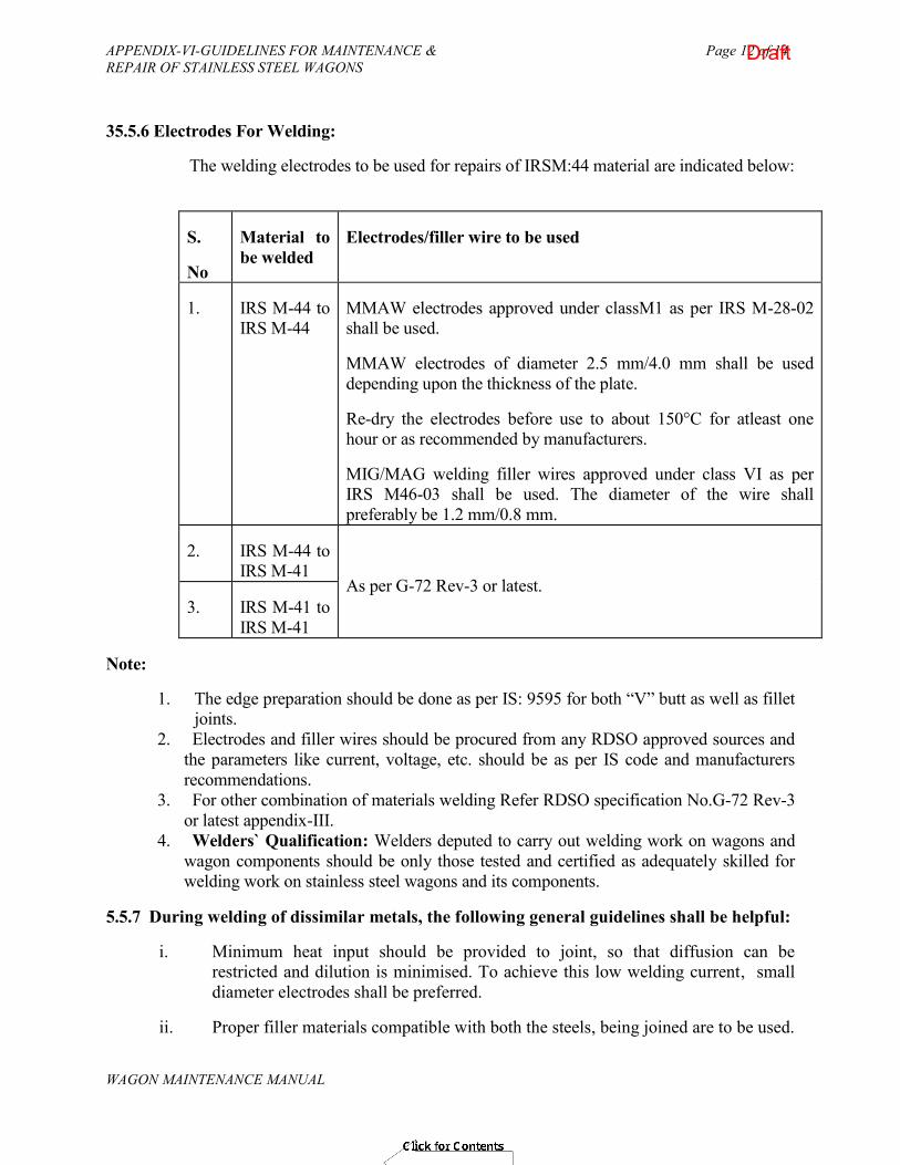
APPENDIX-VI-GUIDELINES FOR MAINTENANCE & Page 12 of 14 REPAIR OF STAINLESS STEEL WAGONS
WAGON MAINTENANCE MANUAL
35.5.6 Electrodes For Welding:
The welding electrodes to be used for repairs of IRSM:44 material are indicated below:
S.
No
Material to be welded
Electrodes/filler wire to be used
1. IRS M-44 to IRS M-44
MMAW electrodes approved under classM1 as per IRS M-28-02 shall be used.
MMAW electrodes of diameter 2.5 mm/4.0 mm shall be used depending upon the thickness of the plate.
Re-dry the electrodes before use to about 150°C for atleast one hour or as recommended by manufacturers.
MIG/MAG welding filler wires approved under class VI as per IRS M46-03 shall be used. The diameter of the wire shall preferably be 1.2 mm/0.8 mm.
2. IRS M-44 to IRS M-41
As per G-72 Rev-3 or latest. 3. IRS M-41 to
IRS M-41
Note:
1. The edge preparation should be done as per IS: 9595 for both “V” butt as well as fillet joints.
2. Electrodes and filler wires should be procured from any RDSO approved sources and the parameters like current, voltage, etc. should be as per IS code and manufacturers recommendations.
3. For other combination of materials welding Refer RDSO specification No.G-72 Rev-3 or latest appendix-III.
4. Welders` Qualification: Welders deputed to carry out welding work on wagons and wagon components should be only those tested and certified as adequately skilled for welding work on stainless steel wagons and its components.
5.5.7 During welding of dissimilar metals, the following general guidelines shall be helpful:
i. Minimum heat input should be provided to joint, so that diffusion can be restricted and dilution is minimised. To achieve this low welding current, small diameter electrodes shall be preferred.
ii. Proper filler materials compatible with both the steels, being joined are to be used.
Draft

APPENDIX-VI-GUIDELINES FOR MAINTENANCE & Page 13 of 14 REPAIR OF STAINLESS STEEL WAGONS
WAGON MAINTENANCE MANUAL
iii. Dilution must be reduced to aslow as possible. Dilution depends on the welding process, process variables and penetration. Hence, proper welding process shall be used with proper setting of process variables (Current, Voltage, Travel speed, Polarity etc.).
iv. When using gas metal arc welding (MIG/MAG) reduced current density is to be employed, so that only dip transfer of metal occurs.
v. The problem of dilution and formation of inter-metallic phases can be minimised by buttering one or both joint faces with a layer of compatible material.
6. SURFACE PREPARATION & PAINTING
i. The surface preparation and painting for underframe of the wagon shall be as per standard specification No.G-72 read with latest amendments.
ii. Surface preparation of the wagon body
Degreasing with petroleum hydrocarbon solvent to IS:1745-1978 (low aromatic grade 145/205) or any other degreaser (applicable for both SS,MS and corten steel).
iii. PAINTING OF WAGON BODY
Wherever the wagon is repaired it must be dressed to smooth surface and proper protective coating i.e. paints to be applied as recommended.
For stainless steel
As specified in the relevant drgs/ specifications or General Standard Specification No. G-72 (Rev.3) read with latest amendments.
iv. The painting of bogies, couplers and air brake equipment shall be done as given in Para 11.2.5 of General Standard Specification No. G-72 (Rev.3) read with latest amendments.
Draft

APPENDIX-VI-GUIDELINES FOR MAINTENANCE & Page 14 of 14 REPAIR OF STAINLESS STEEL WAGONS
WAGON MAINTENANCE MANUAL
References:
(i) General guidelines for fabrication of stainless steel (IRS M:44) wagons and requirements for ensuring quality during manufacturing issued by Wagon Directorate, RDSO in Oct. 2007.
(ii) Guidelines and facilities required for fabrication/maintenance of stainless steel wagons Issued by CAMTECH vide No. Camtech .M/W/SS Wagon-1.0 in December-09.
(iii) Maintenance Manual of LHB Coaches /Wagons a draft copy by CAMTECH/Gwalior.
(iv) Welding procedure for joining various types of stainless steel parts with mild steel/corten steel parts used in carriage & Wagons based on procedure No. MC-97 Issued by M&C Directorate, RDSO, Luck now
(v) Minutes of the seminar on welding technology-“Focus on Railway workshops”, held in Railway Board on 18.01.2011.
(vi) General standard specification No. G-72, Issued by wagon Directorate, RDSO, Lucknow.
Draft