Embed Size (px)
Citation preview
Indholdsfortegnelse
Danvent Air Handling Units
SERVICEMANUAL

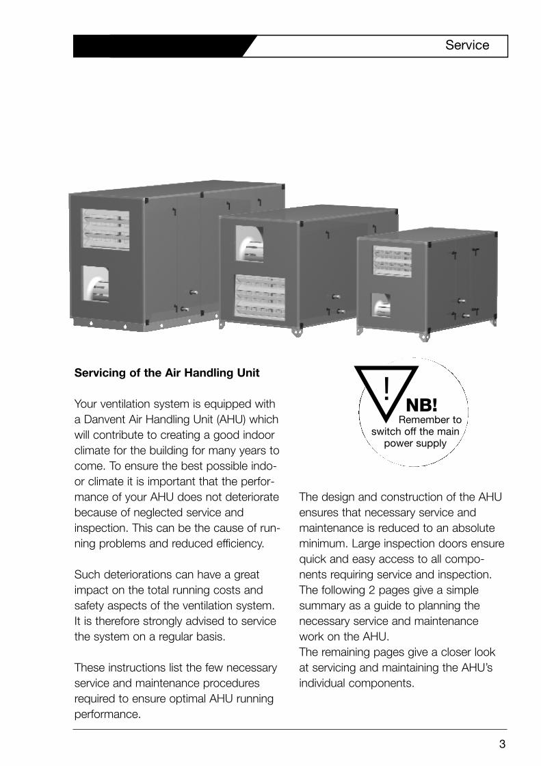
Servicing of the Air Handling Unit
Your ventilation system is equipped witha Danvent Air Handling Unit (AHU) whichwill contribute to creating a good indoorclimate for the building for many years tocome. To ensure the best possible indo-or climate it is important that the perfor-mance of your AHU does not deterioratebecause of neglected service andinspection. This can be the cause of run-ning problems and reduced efficiency.
Such deteriorations can have a greatimpact on the total running costs andsafety aspects of the ventilation system.It is therefore strongly advised to servicethe system on a regular basis.
These instructions list the few necessaryservice and maintenance proceduresrequired to ensure optimal AHU runningperformance.
The design and construction of the AHUensures that necessary service andmaintenance is reduced to an absoluteminimum. Large inspection doors ensurequick and easy access to all compo-nents requiring service and inspection.The following 2 pages give a simplesummary as a guide to planning thenecessary service and maintenancework on the AHU.The remaining pages give a closer lookat servicing and maintaining the AHU’sindividual components.
Service
3
NB! Remember to
switch off the main power supply
!
Air Handling Unit
Clean the AHU
Check the seals and closing mechanisms
DampersCheck the air-tightness
Bag filtersReplace the filter cells and check the seals at the filter cells
Compact filterReplace the filter cells
Rotary heat exchanger
Check the condition of the rotor and that it turns easily
Check the brush seals
Check the Varimatic drive system
Check and tighten the belt drive
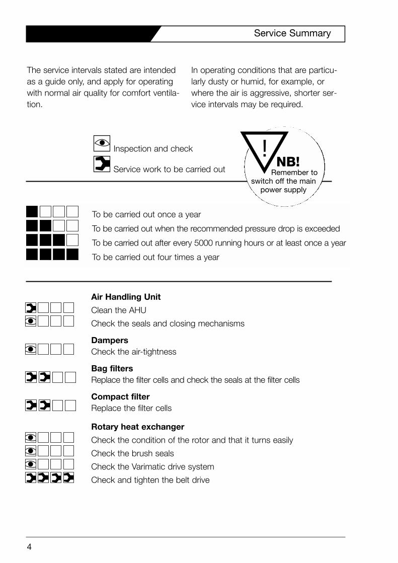
To be carried out once a year
To be carried out when the recommended pressure drop is exceeded
To be carried out after every 5000 running hours or at least once a year
To be carried out four times a year
Inspection and check
Service work to be carried out
4
Service Summary
!NB!
Remember to switch off the main
power supply
The service intervals stated are intendedas a guide only, and apply for operatingwith normal air quality for comfort ventila-tion.
In operating conditions that are particu-larly dusty or humid, for example, orwhere the air is aggressive, shorter ser-vice intervals may be required.
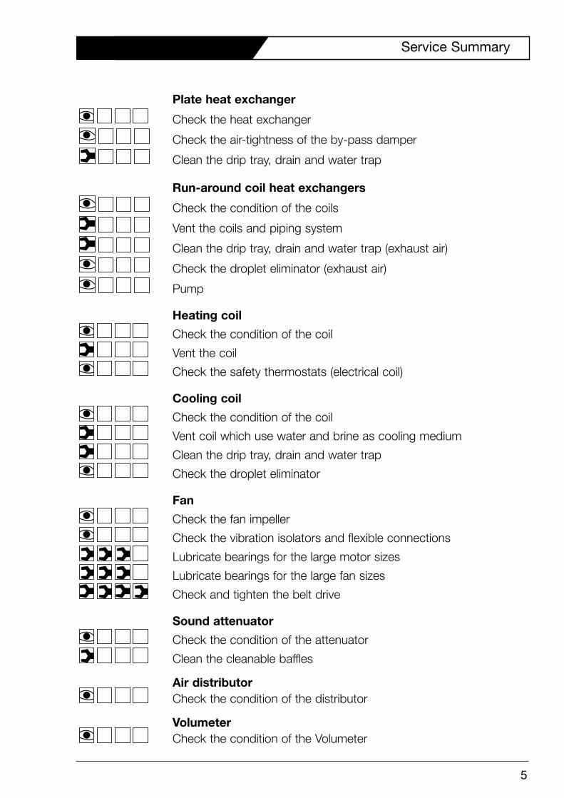
Plate heat exchanger
Check the heat exchanger
Check the air-tightness of the by-pass damper
Clean the drip tray, drain and water trap
Run-around coil heat exchangers
Check the condition of the coils
Vent the coils and piping system
Clean the drip tray, drain and water trap (exhaust air)
Check the droplet eliminator (exhaust air)
Pump
Heating coil
Check the condition of the coil
Vent the coil
Check the safety thermostats (electrical coil)
Cooling coil
Check the condition of the coil
Vent coil which use water and brine as cooling medium
Clean the drip tray, drain and water trap
Check the droplet eliminator
Fan
Check the fan impeller
Check the vibration isolators and flexible connections
Lubricate bearings for the large motor sizes
Lubricate bearings for the large fan sizes
Check and tighten the belt drive
Sound attenuator
Check the condition of the attenuator
Clean the cleanable baffles
Air distributorCheck the condition of the distributor
VolumeterCheck the condition of the Volumeter
5
Service Summary
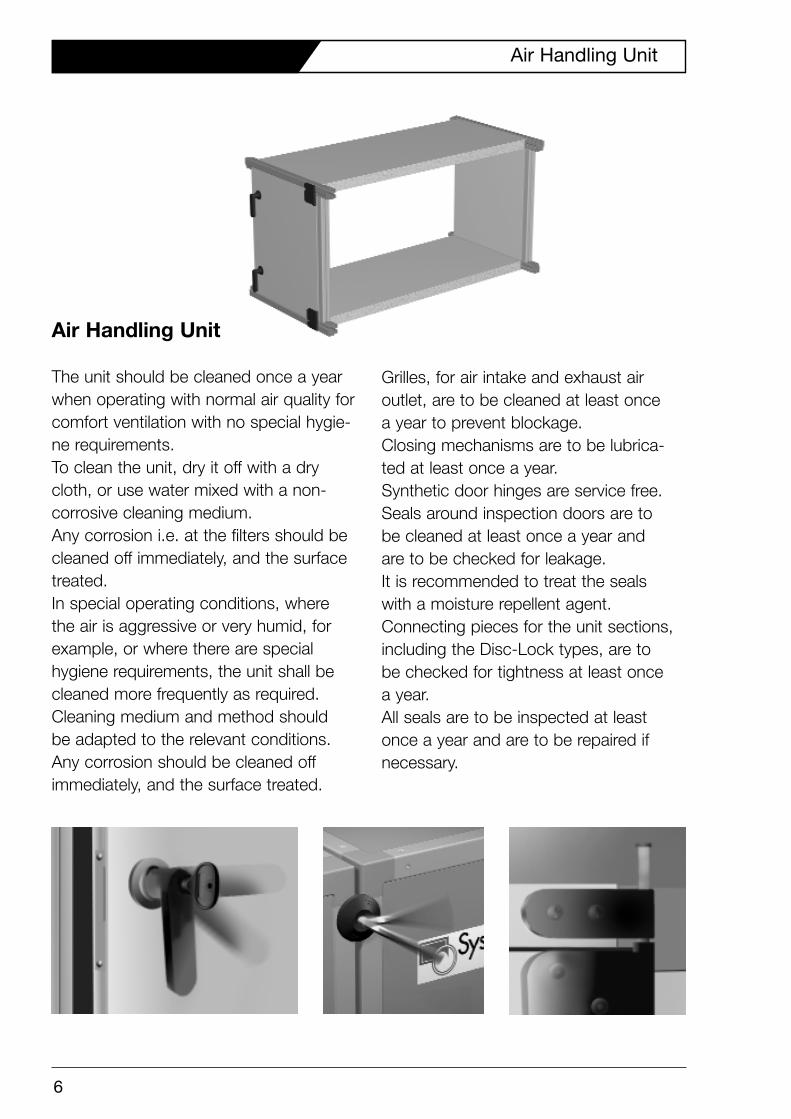
Air Handling Unit
The unit should be cleaned once a yearwhen operating with normal air quality forcomfort ventilation with no special hygie-ne requirements.To clean the unit, dry it off with a drycloth, or use water mixed with a non-corrosive cleaning medium.Any corrosion i.e. at the filters should becleaned off immediately, and the surfacetreated.In special operating conditions, wherethe air is aggressive or very humid, forexample, or where there are special hygiene requirements, the unit shall becleaned more frequently as required.Cleaning medium and method should be adapted to the relevant conditions.Any corrosion should be cleaned off immediately, and the surface treated.
Grilles, for air intake and exhaust air outlet, are to be cleaned at least once a year to prevent blockage.Closing mechanisms are to be lubrica-ted at least once a year.Synthetic door hinges are service free.Seals around inspection doors are to be cleaned at least once a year and are to be checked for leakage. It is recommended to treat the seals with a moisture repellent agent.Connecting pieces for the unit sections,including the Disc-Lock types, are to be checked for tightness at least once a year. All seals are to be inspected at leastonce a year and are to be repaired ifnecessary.
6
Air Handling Unit
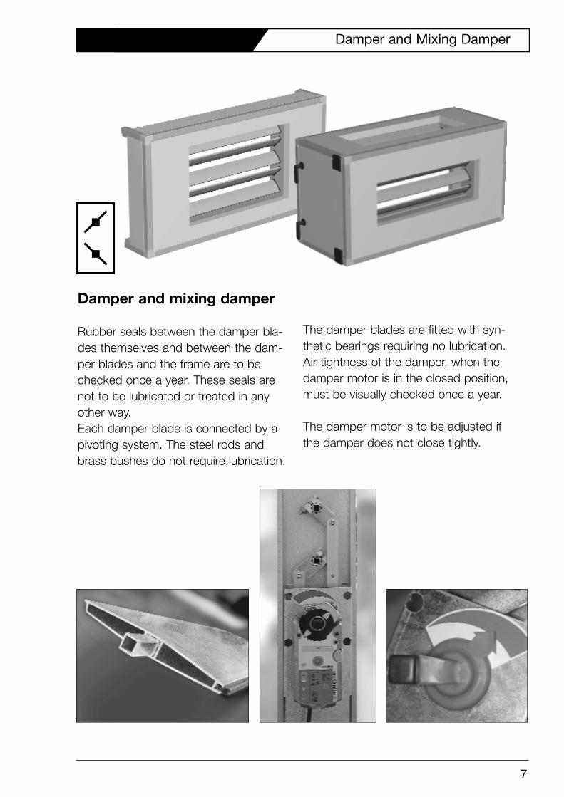
Damper and mixing damper
Rubber seals between the damper bla-des themselves and between the dam-per blades and the frame are to bechecked once a year. These seals arenot to be lubricated or treated in anyother way. Each damper blade is connected by apivoting system. The steel rods andbrass bushes do not require lubrication.
The damper blades are fitted with syn-thetic bearings requiring no lubrication.Air-tightness of the damper, when thedamper motor is in the closed position,must be visually checked once a year.
The damper motor is to be adjusted ifthe damper does not close tightly.
7
Damper and Mixing Damper
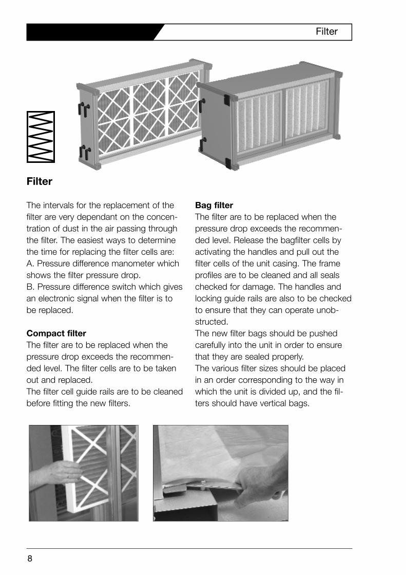
Filter
The intervals for the replacement of thefilter are very dependant on the concen-tration of dust in the air passing throughthe filter. The easiest ways to determinethe time for replacing the filter cells are:A. Pressure difference manometer whichshows the filter pressure drop.B. Pressure difference switch which givesan electronic signal when the filter is tobe replaced.
Compact filterThe filter are to be replaced when thepressure drop exceeds the recommen-ded level. The filter cells are to be takenout and replaced. The filter cell guide rails are to be cleanedbefore fitting the new filters.
Bag filterThe filter are to be replaced when thepressure drop exceeds the recommen-ded level. Release the bagfilter cells byactivating the handles and pull out the filter cells of the unit casing. The frameprofiles are to be cleaned and all sealschecked for damage. The handles andlocking guide rails are also to be checkedto ensure that they can operate unob-structed. The new filter bags should be pushedcarefully into the unit in order to ensurethat they are sealed properly.The various filter sizes should be placedin an order corresponding to the way inwhich the unit is divided up, and the fil-ters should have vertical bags.
8
Filter
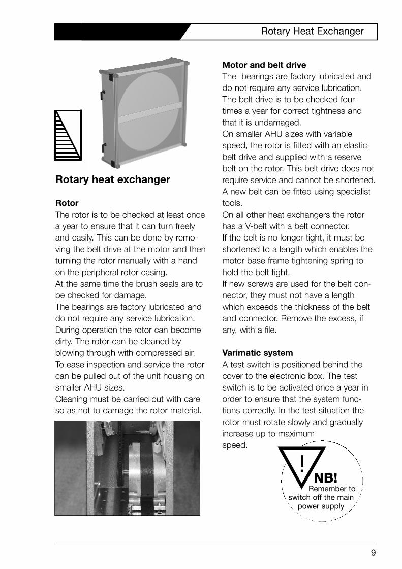
Rotary heat exchanger
RotorThe rotor is to be checked at least oncea year to ensure that it can turn freelyand easily. This can be done by remo-ving the belt drive at the motor and thenturning the rotor manually with a handon the peripheral rotor casing. At the same time the brush seals are tobe checked for damage.The bearings are factory lubricated anddo not require any service lubrication.During operation the rotor can becomedirty. The rotor can be cleaned by blowing through with compressed air. To ease inspection and service the rotorcan be pulled out of the unit housing onsmaller AHU sizes. Cleaning must be carried out with careso as not to damage the rotor material.
Motor and belt driveThe bearings are factory lubricated anddo not require any service lubrication.The belt drive is to be checked fourtimes a year for correct tightness andthat it is undamaged.On smaller AHU sizes with variablespeed, the rotor is fitted with an elasticbelt drive and supplied with a reservebelt on the rotor. This belt drive does notrequire service and cannot be shortened.A new belt can be fitted using specialisttools. On all other heat exchangers the rotorhas a V-belt with a belt connector.If the belt is no longer tight, it must beshortened to a length which enables themotor base frame tightening spring tohold the belt tight. If new screws are used for the belt con-nector, they must not have a lengthwhich exceeds the thickness of the beltand connector. Remove the excess, ifany, with a file.
Varimatic systemA test switch is positioned behind thecover to the electronic box. The testswitch is to be activated once a year inorder to ensure that the system func-tions correctly. In the test situation therotor must rotate slowly and gradually increase up to maximum speed.
9
Rotary Heat Exchanger
NB! Remember to
switch off the main power supply
!
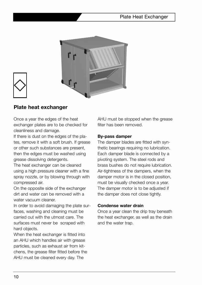
Plate heat exchanger
Once a year the edges of the heatexchanger plates are to be checked forcleanliness and damage.If there is dust on the edges of the pla-tes, remove it with a soft brush. If greaseor other such substances are present, then the edges must be washed usinggrease dissolving detergents.The heat exchanger can be cleanedusing a high pressure cleaner with a finespray nozzle, or by blowing through withcompressed air.On the opposite side of the exchangerdirt and water can be removed with awater vacuum cleaner.In order to avoid damaging the plate sur-faces, washing and cleaning must becarried out with the utmost care. Thesurfaces must never be scraped withhard objects. When the heat exchanger is fitted intoan AHU which handles air with greaseparticles, such as exhaust air from kit-chens, the grease filter fitted before theAHU must be cleaned every day. The
AHU must be stopped when the greasefilter has been removed.
By-pass damperThe damper blades are fitted with syn-thetic bearings requiring no lubrication.Each damper blade is connected by apivoting system. The steel rods andbrass bushes do not require lubrication.Air-tightness of the dampers, when thedamper motor is in the closed position,must be visually checked once a year.The damper motor is to be adjusted ifthe damper does not close tightly.
Condense water drainOnce a year clean the drip tray beneaththe heat exchanger, as well as the drainand the water trap.
10
Plate Heat Exchanger
11
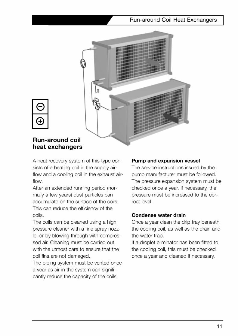
Run-around coil heat exchangers
A heat recovery system of this type con-sists of a heating coil in the supply air-flow and a cooling coil in the exhaust air-flow.After an extended running period (nor-mally a few years) dust particles canaccumulate on the surface of the coils.This can reduce the efficiency of thecoils.The coils can be cleaned using a highpressure cleaner with a fine spray nozz-le, or by blowing through with compres-sed air. Cleaning must be carried outwith the utmost care to ensure that thecoil fins are not damaged.The piping system must be vented oncea year as air in the system can signifi-cantly reduce the capacity of the coils.
Pump and expansion vesselThe service instructions issued by thepump manufacturer must be followed.The pressure expansion system must bechecked once a year. If necessary, thepressure must be increased to the cor-rect level.
Condense water drainOnce a year clean the drip tray beneaththe cooling coil, as well as the drain andthe water trap.If a droplet eliminator has been fitted tothe cooling coil, this must be checkedonce a year and cleaned if necessary.
Run-around Coil Heat Exchangers
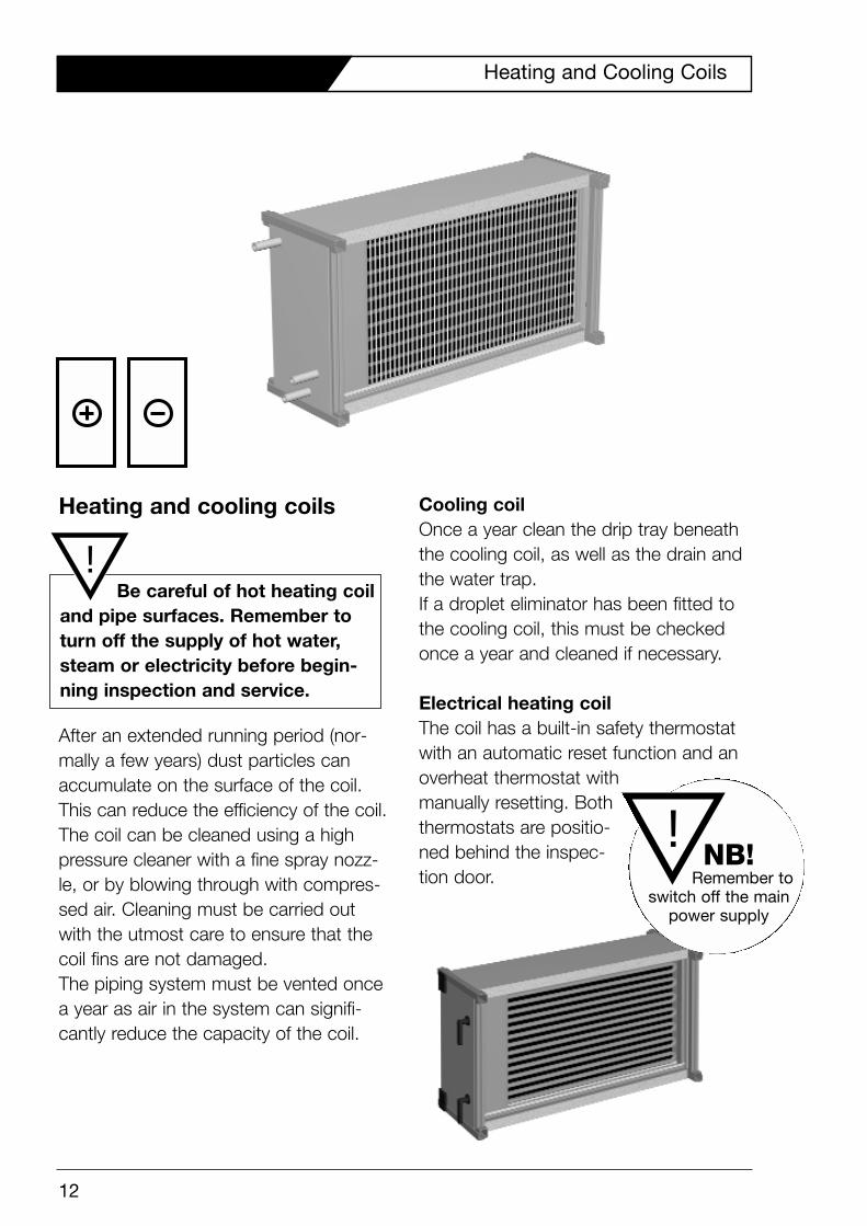
Heating and cooling coils
After an extended running period (nor-mally a few years) dust particles canaccumulate on the surface of the coil.This can reduce the efficiency of the coil.The coil can be cleaned using a highpressure cleaner with a fine spray nozz-le, or by blowing through with compres-sed air. Cleaning must be carried outwith the utmost care to ensure that thecoil fins are not damaged.The piping system must be vented oncea year as air in the system can signifi-cantly reduce the capacity of the coil.
Cooling coilOnce a year clean the drip tray beneaththe cooling coil, as well as the drain andthe water trap. If a droplet eliminator has been fitted tothe cooling coil, this must be checkedonce a year and cleaned if necessary.
Electrical heating coilThe coil has a built-in safety thermostatwith an automatic reset function and anoverheat thermostat withmanually resetting. Boththermostats are positio-ned behind the inspec-tion door.
12
Heating and Cooling Coils
Be careful of hot heating coiland pipe surfaces. Remember toturn off the supply of hot water,steam or electricity before begin-ning inspection and service.
!
!NB!
Remember to switch off the main
power supply
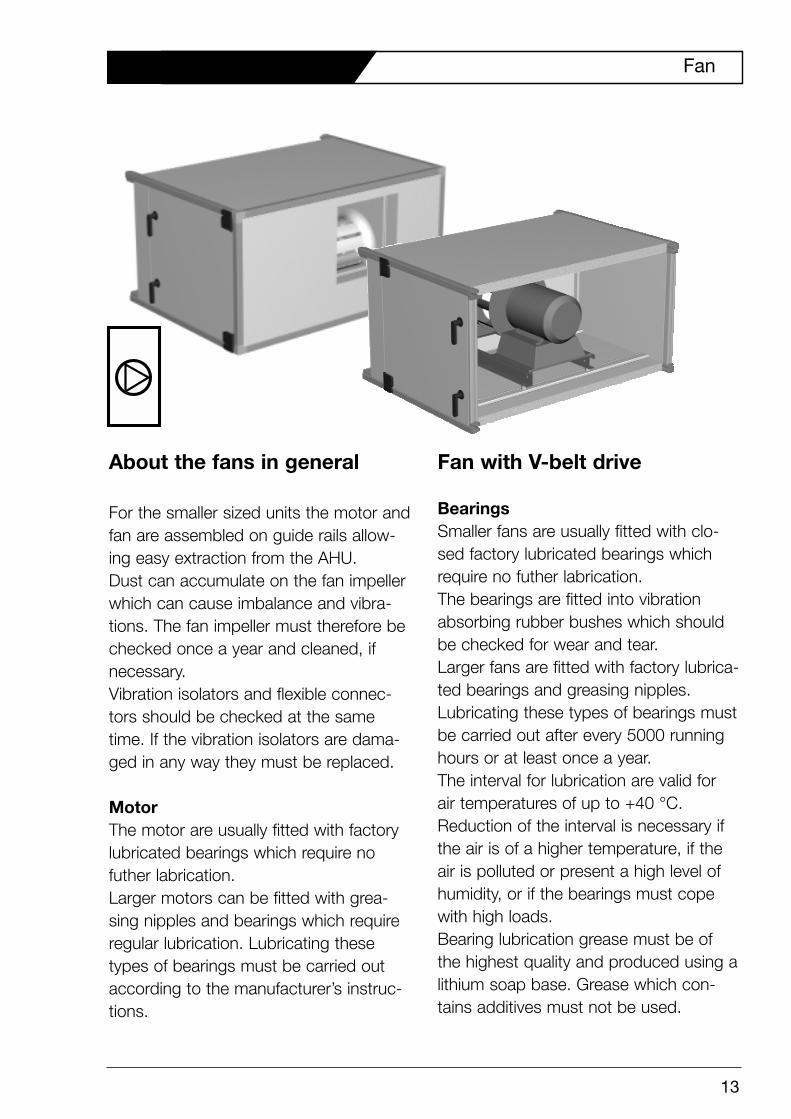
About the fans in general
For the smaller sized units the motor andfan are assembled on guide rails allow-ing easy extraction from the AHU.Dust can accumulate on the fan impellerwhich can cause imbalance and vibra-tions. The fan impeller must therefore bechecked once a year and cleaned, ifnecessary.Vibration isolators and flexible connec-tors should be checked at the sametime. If the vibration isolators are dama-ged in any way they must be replaced.
MotorThe motor are usually fitted with factorylubricated bearings which require no futher labrication.Larger motors can be fitted with grea-sing nipples and bearings which requireregular lubrication. Lubricating thesetypes of bearings must be carried outaccording to the manufacturer’s instruc-tions.
Fan with V-belt drive
BearingsSmaller fans are usually fitted with clo-sed factory lubricated bearings whichrequire no futher labrication.The bearings are fitted into vibrationabsorbing rubber bushes which shouldbe checked for wear and tear.Larger fans are fitted with factory lubrica-ted bearings and greasing nipples.Lubricating these types of bearings mustbe carried out after every 5000 runninghours or at least once a year.The interval for lubrication are valid for air temperatures of up to +40 °C.Reduction of the interval is necessary ifthe air is of a higher temperature, if theair is polluted or present a high level ofhumidity, or if the bearings must copewith high loads. Bearing lubrication grease must be ofthe highest quality and produced using alithium soap base. Grease which con-tains additives must not be used.
13
Fan
Care must be taken not to over greasethe bearings. This can result in thebearings becoming overheated andeventually damaged.After lubrication of the bearings the fanshould be started as follows:Start the fan and let it run for approxima-tely 2 minutes. The fan must then bestopped and the bearings left to cooldown until cold. This process is to berepeated a few times before the fan isallowed to run continuously.
V-belt driveThe belt drive is to be checked 4 times ayear. If one or more of the belts is wornthen all belts must be replaced. Newand used belts must never be usedtogether as they have different lengths.
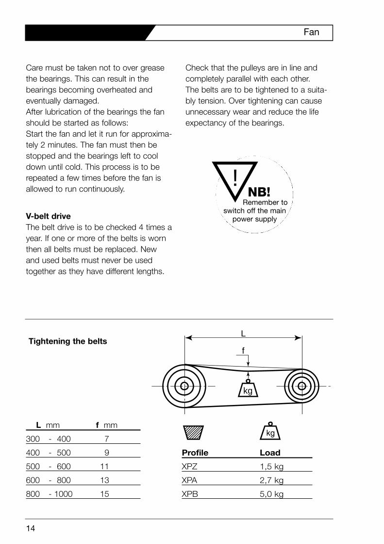
Check that the pulleys are in line andcompletely parallel with each other. The belts are to be tightened to a suita-bly tension. Over tightening can causeunnecessary wear and reduce the lifeexpectancy of the bearings.
kg
f
LTightening the belts
Profile Load
XPZ 1,5 kg
XPA 2,7 kg
XPB 5,0 kg
L mm f mm
300 - 400 7
400 - 500 9
500 - 600 11
600 - 800 13
800 - 1000 15
14
Fan
!NB!
Remember to switch off the main
power supply
15
Sound Attenuator and Air Distributor
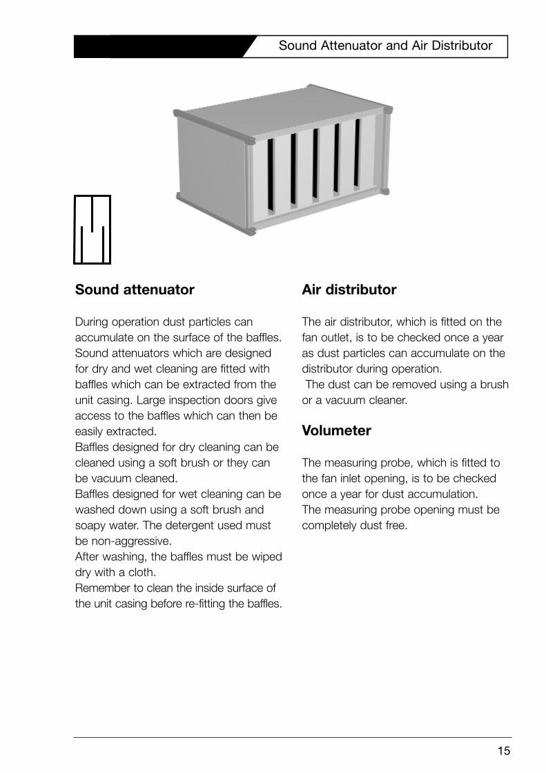
Sound attenuator
During operation dust particles canaccumulate on the surface of the baffles.Sound attenuators which are designedfor dry and wet cleaning are fitted withbaffles which can be extracted from theunit casing. Large inspection doors giveaccess to the baffles which can then beeasily extracted.Baffles designed for dry cleaning can becleaned using a soft brush or they canbe vacuum cleaned.Baffles designed for wet cleaning can bewashed down using a soft brush andsoapy water. The detergent used mustbe non-aggressive.After washing, the baffles must be wipeddry with a cloth.Remember to clean the inside surface ofthe unit casing before re-fitting the baffles.
Air distributor
The air distributor, which is fitted on thefan outlet, is to be checked once a yearas dust particles can accumulate on thedistributor during operation. The dust can be removed using a brush
or a vacuum cleaner.
Volumeter
The measuring probe, which is fitted tothe fan inlet opening, is to be checkedonce a year for dust accumulation.The measuring probe opening must becompletely dust free.
Indholdsfortegnelse
Systemair A/S
Ved Milepælen 7
DK-8361 Hasselager
Denmark
Tel.: +45 87 38 75 00
Fax: +45 87 38 75 01
www.systemair.dk
02.2005
GB