Embed Size (px)
Citation preview

Maintenance and Service GuideHP Notebook Expansion Base
Document Part Number: 344524-001
January 2004
This guide is a troubleshooting reference used for maintaining and servicing the HP Notebook Expansion Base. It provides comprehensive information on identifying Expansion Base features, components, and spare parts; troubleshooting problems; and performing disassembly procedures.

© Copyright 2004 Hewlett-Packard Development Company, L.P.
The information contained herein is subject to change without notice. The only warranties for HP products and services are set forth in the express warranty statements accompanying such products and services. Nothing herein should be construed as constituting an additional warranty. HP shall not be liable for technical or editorial errors or omissions contained herein.
Maintenance and Service GuideHP Notebook Expansion BaseFirst Edition January 2004Document Part Number: 344524-001

Contents
1 Product Description
1.1 Features . . . . . . . . . . . . . . . . . . . . . . . . . . . . . . . . . . . 1–21.2 External Components . . . . . . . . . . . . . . . . . . . . . . . . 1–31.3 Wireless Accessories. . . . . . . . . . . . . . . . . . . . . . . . . 1–91.4 Design Overview. . . . . . . . . . . . . . . . . . . . . . . . . . . 1–10
2 Troubleshooting
Before Replacing Parts. . . . . . . . . . . . . . . . . . . . . . . . . . . 2–1Problems and Solutions . . . . . . . . . . . . . . . . . . . . . . . . . . 2–2
3 Illustrated Parts Catalog
3.1 Serial Number Location . . . . . . . . . . . . . . . . . . . . . . 3–13.2 HP Notebook Expansion Base
Major Components . . . . . . . . . . . . . . . . . . . . . . . . . . 3–2
4 Removal and Replacement Preliminaries
4.1 Tools Required . . . . . . . . . . . . . . . . . . . . . . . . . . . . . 4–14.2 Service Considerations . . . . . . . . . . . . . . . . . . . . . . . 4–1
Plastic Parts . . . . . . . . . . . . . . . . . . . . . . . . . . . . . . . . 4–2Cables and Connectors . . . . . . . . . . . . . . . . . . . . . . . 4–2
4.3 Preventing Electrostatic Damage . . . . . . . . . . . . . . . 4–24.4 Packaging and Transporting Precautions . . . . . . . . . 4–34.5 Workstation Precautions . . . . . . . . . . . . . . . . . . . . . . 4–44.6 Grounding Equipment and Methods . . . . . . . . . . . . . 4–5
Maintenance and Service Guide iii

Contents
5 Removal and Replacement Procedures
5.1 Serial Number . . . . . . . . . . . . . . . . . . . . . . . . . . . . . . 5–25.2 Disassembly Sequence Chart . . . . . . . . . . . . . . . . . . 5–35.3 Preparing the HP Notebook Expansion Base
for Disassembly. . . . . . . . . . . . . . . . . . . . . . . . . . . . . 5–45.4 Base Plate . . . . . . . . . . . . . . . . . . . . . . . . . . . . . . . . . 5–55.5 Upper Chassis . . . . . . . . . . . . . . . . . . . . . . . . . . . . . . 5–65.6 Power Supply . . . . . . . . . . . . . . . . . . . . . . . . . . . . . 5–105.7 System Board . . . . . . . . . . . . . . . . . . . . . . . . . . . . . 5–125.8 Front Tray Cover. . . . . . . . . . . . . . . . . . . . . . . . . . . 5–145.9 Back Panel. . . . . . . . . . . . . . . . . . . . . . . . . . . . . . . . 5–165.10 Expansion Cable . . . . . . . . . . . . . . . . . . . . . . . . . . 5–175.11 Speaker Assembly. . . . . . . . . . . . . . . . . . . . . . . . . 5–185.12 Front Case . . . . . . . . . . . . . . . . . . . . . . . . . . . . . . . 5–20
6 Specifications
A Connector Pin Assignments
B Power Cord Set Requirements
3-Conductor Power Cord Set . . . . . . . . . . . . . . . . . . . . . . B–1General Requirements . . . . . . . . . . . . . . . . . . . . . . . . . . . B–1Country-Specific Requirements . . . . . . . . . . . . . . . . . . . . B–2
C Screw Listing
Index
iv Maintenance and Service Guide

1Product Description
The HP Notebook Expansion Base expands the connectivity of HP Compaq Business Notebook nx9100 Series; HP Pavilion zd7000, zv5000, and zx5000 Series notebook PCs; and the Compaq Presario R3000 Series notebook PC. The Expansion Base provides an efficient, less-cluttered work environment, improved cable management, and wireless peripherals. It eliminates the need to purchase a separate monitor, external speakers, USB hub, and a wireless keyboard and mouse kit.
HP Notebook Expansion Base
Maintenance and Service Guide 1–1
Product Description
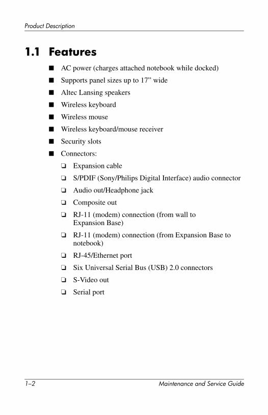
1.1 Features■ AC power (charges attached notebook while docked)
■ Supports panel sizes up to 17” wide
■ Altec Lansing speakers
■ Wireless keyboard
■ Wireless mouse
■ Wireless keyboard/mouse receiver
■ Security slots
■ Connectors:
❏ Expansion cable
❏ S/PDIF (Sony/Philips Digital Interface) audio connector
❏ Audio out/Headphone jack
❏ Composite out
❏ RJ-11 (modem) connection (from wall to Expansion Base)
❏ RJ-11 (modem) connection (from Expansion Base to notebook)
❏ RJ-45/Ethernet port
❏ Six Universal Serial Bus (USB) 2.0 connectors
❏ S-Video out
❏ Serial port
1–2 Maintenance and Service Guide

Product Description
1.2 External ComponentsThe external components on the front panel of the Expansion Base are shown below and described in Table 1-2.
Front components
Maintenance and Service Guide 1–3

Product Description
Table 1-2Front Components
Item Component Function
1 Expansion cable Connects the HP Notebook Expansion Base to the notebook computer.
2 Stereo speaker assembly
Produces stereo sound from the notebook.
3 Volume down button Lowers system volume.
4 Mute button Mutes or restores volume.
5 Volume up button Increases system volume.
6 Connection indicator light
Glows solid blue when the notebook is connected correctly.
1–4 Maintenance and Service Guide
Product Description
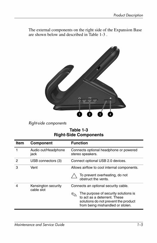
The external components on the right side of the Expansion Base are shown below and described in Table 1-3 .
Right-side components
Table 1-3Right-Side Components
Item Component Function
1 Audio out/Headphone jack
Connects optional headphone or powered stereo speakers.
2 USB connectors (3) Connect optional USB 2.0 devices.
3 Vent Allows airflow to cool internal components.
Ä To prevent overheating, do not obstruct the vents.
4 Kensington security cable slot
Connects an optional security cable.
✎ The purpose of security solutions is to act as a deterrent. These solutions do not prevent the product from being mishandled or stolen.
Maintenance and Service Guide 1–5
Product Description
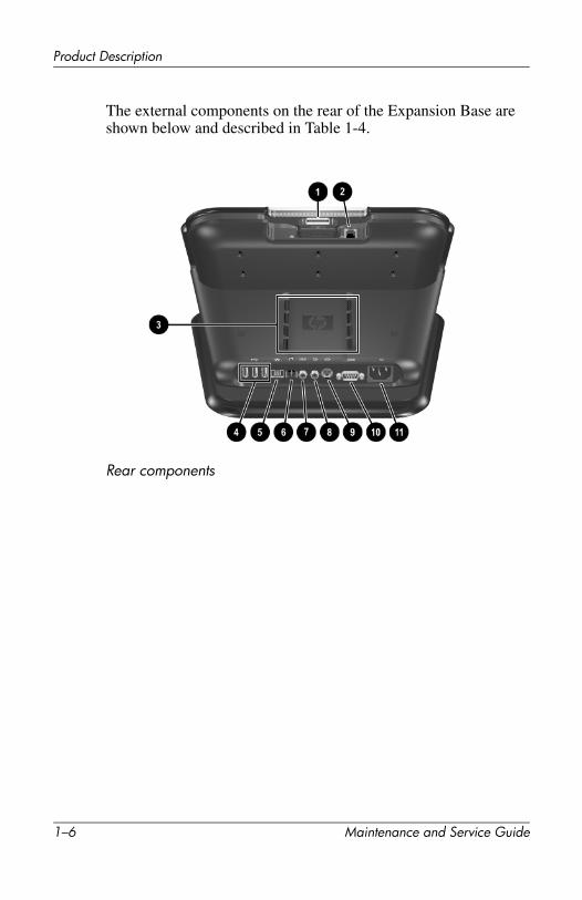
The external components on the rear of the Expansion Base are shown below and described in Table 1-4.
Rear components
1–6 Maintenance and Service Guide

Product Description
Table 1-4Rear Panel Components
Item Component Function
1 Expansion cable Connects the Expansion Base to a notebook computer.
2 RJ-11 jack Connects a modem cable from the Expansion Base to a notebook.
3 Vents (2) Allow airflow to cool internal components.
Ä To prevent overheating, do not obstruct the vents.
4 USB connectors (3) Connect optional USB 2.0 devices
5 RJ-45 network jack Connects an Ethernet network cable from the Expansion Base to an RJ-45 wall jack.
6 RJ-11 jack Connects the Expansion Base to an RJ-11 telephone wall jack.
7 S/PDIF (Sony/Philips Digital Interface) audio connector
Connects high-end digital systems, such as surround sound or a home theatre.
8 TV out/Composite jack Connects a television, VCR, camcorder, or projector.
9 TV out/ S-Video jack Connects an optional S-Video device, such as a television, VCR, camcorder, projector, or video capture card.
10 Serial connector Connects a serial device, such as a mouse.
11 Power connector Connects AC power cord. Charges notebook while docked.
Maintenance and Service Guide 1–7
Product Description
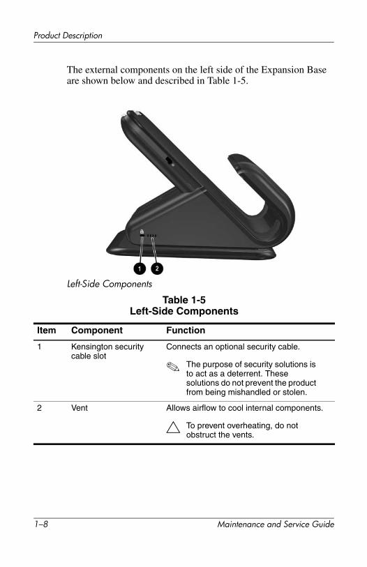
The external components on the left side of the Expansion Base are shown below and described in Table 1-5.
Left-Side Components
Table 1-5Left-Side Components
Item Component Function
1 Kensington security cable slot
Connects an optional security cable.
✎ The purpose of security solutions is to act as a deterrent. These solutions do not prevent the product from being mishandled or stolen.
2 Vent Allows airflow to cool internal components.
Ä To prevent overheating, do not obstruct the vents.
1–8 Maintenance and Service Guide

Product Description
1.3 Wireless Accessories
Table 1-6Wireless Accessories
Item Component Function
1 Wireless keyboard Connects to the Expansion Base without a cable.
2 Receiver Connects to a USB port on the Expansion Base. Allows connection between the Expansion Base and the wireless keyboard and mouse.
3 Wireless mouse Connects to the Expansion Base without a cable.
Maintenance and Service Guide 1–9

Product Description
1.4 Design OverviewThis section presents a design overview of key parts and features of the HP Notebook Expansion Base. Refer to Chapter 3, “Illustrated Parts Catalog,” to identify replacement parts, and Chapter 5, “Removal and Replacement Procedures,” for disassembly steps.
The Expansion Base provides the following device connections:
■ Expansion cable
■ S/PDIF (Sony/Philips Digital Interface) audio connector
■ Audio out/Headphone jack
■ Composite out
■ RJ-11 (modem) connection (from wall to Expansion Base)
■ RJ-11 (modem) connection (from Expansion Base to notebook)
■ RJ-45/Ethernet port
■ Six USB 2.0 connectors
■ S-Video out
■ Serial port
The HP Notebook Expansion Base uses electrical fans for ventilation. The fans are controlled by a temperature sensor and are designed to turn on automatically when high temperature conditions exist. These conditions are affected by high external temperatures, system power consumption, power management/battery conservation configurations, and software applications. Exhaust air is displaced through the ventilation grill located on the right side, left side, and rear panel of the unit.
ÄCAUTION: To properly ventilate the HP Notebook Expansion Base, allow at least a 7.6-cm (3-inch) clearance on the left and right sides of the unit.
1–10 Maintenance and Service Guide

2Troubleshooting
ÅWARNING: Only authorized technicians trained by HP should repair this equipment. All troubleshooting and repair procedures are detailed to allow only subassembly/module level repair. Because of the complexity of the individual boards and subassemblies, do not attempt to make repairs at the component level or modifications to any printed wiring board. Improper repairs can create a safety hazard. Any indication of component replacement or printed wiring board modification may void any warranty or exchange allowances.
This chapter contains troubleshooting information for the HP Notebook Expansion Base. Carefully match the symptoms of the malfunction against the problem description in the Troubleshooting tables to avoid a misdiagnosis. Refer toChapter 5 for all removal and replacement procedures.
Follow these guidelines when troubleshooting:
■ Complete the recommended actions in the order in which they are given.
■ When the problem is resolved, do not complete the remaining troubleshooting steps.
Before Replacing PartsWhen troubleshooting a problem, check the following list for possible solutions before replacing parts:
■ Verify that cables are connected properly to the suspected defective part.
■ Verify that all required device drivers are installed on the notebook.
Maintenance and Service Guide 2–1

Troubleshooting
Problems and SolutionsThe following tables list possible problems, the possible cause of each problem, and the recommended solution.
Table 2-1
Power Problems and Solutions
Problem Possible Cause Solution
The blue indicator light does not come on.
The notebook is not powered on.
Turn on the notebook.
The Expansion Base is not connected to AC power.
Verify that the AC cable is properly connected to the Expansion Base and to an AC power outlet.
The expansion cable on the Expansion Base is not properly connected to the expansion connector on the notebook.
Turn off the notebook and unplug the expansion cable. Then plug the expansion cable back in to the notebook and turn the notebook on.
If the above solutions are unsuccessful, the expansion cable may be damaged.
Replace the expansion cable. (Section 5.10)
If the above solutions are unsuccessful, the power supply may be malfunctioning.
Replace the power supply. (Section 5.6)
The notebook shuts down.
The Expansion Base is not plugged into an AC power outlet, draining the notebook battery pack.
Plug the Expansion Base into an AC power outlet.
If the above solution is unsuccessful, the power supply may be malfunctioning.
Replace the power supply. (Section 5.6)
2–2 Maintenance and Service Guide

Troubleshooting
Table 2-2
External Device Problems and Solutions
Problem Possible Cause Solution
A new device is not recognized as part of the notebook system.
The device cable or power cord is loose.
■ Test the device first by plugging it into the appropriate notebook connector. Note that composite TV out and serial connectors are not supported on the notebook.
■ Ensure that all cables are securely connected to the device and the Expansion Base.
■ Ensure that all power cords are securely connected to the device and to an electrical outlet.
Device cabling is incorrect. Ensure that the device cable is in the correct connector on the Expansion Base.
The device was connected while the system was on.
Turn off the notebook, turn on the device (if applicable), and then turn on the notebook.
Device drivers may need to be installed on the notebook.
Install drivers according to the device manufacturer’s instructions.
If the above solutions are unsuccessful, the system board may be malfunctioning.
Replace the system board. (Section 5.7)
Maintenance and Service Guide 2–3

3Illustrated Parts Catalog
This chapter provides an illustrated parts breakdown and a reference for spare part numbers and option part numbers.
3.1 Serial Number LocationWhen ordering parts or requesting information, provide the Expansion Base serial number and model number located on the bottom of the base plate.
Serial number location
Maintenance and Service Guide 3–1

Illustrated Parts Catalog
3.2 HP Notebook Expansion Base Major Components
HP Notebook Expansion Base major components
3–2 Maintenance and Service Guide

Illustrated Parts Catalog
Table 3-1Spare Parts: HP Notebook Expansion Base
Major Components
Item DescriptionSpare Part Number
1 Back panel (with modem connector and cable) 347433-001
2 Upper chassis 347434-001
3 Expansion cable 347435-001
4 Speaker assembly 347431-001
5 Front tray cover 347432-001
Miscellaneous Plastics Kit (including the following components)
347436-001
6 Front case
7a Rear cover
7b Base enclosure
7c Base plate
8 Power supply and shield 347438-001
9 System board 347437-001
Maintenance and Service Guide 3–3

Illustrated Parts Catalog
HP Notebook Expansion Base miscellaneous components
3–4 Maintenance and Service Guide

Illustrated Parts Catalog
Table 3-1Spare Parts: HP Notebook Expansion Base Miscellaneous
Components
Item DescriptionSpare Part Number
1 Receiver 348088-001
2 Wireless mouse 348087-001
3 Wireless keyboard
ADPAustraliaBrazilCanada (Fr.)Czech Rep.DenmarkEuropeFranceGermanyGreeceHong KongHungaryIndiaIcelandIsraelItalyJapanKorea
348086-371348086-011348086-201348086-121348086-221348086-081348086-021348086-051348086-041348086-151348086-DC1348086-211348086-D61348086-DD1348086-BB1348086-061348086-291348086-AD1
Latin AmericaThe NetherlandsNorwayPolandPortugalPeoples Republic of ChinaRussiaSaudi ArabiaSweden/FinlandSloveniaSpainThailandTurkeyTaiwanUnited KingdomUnited States
348086-161348086-331348086-091348086-241348086-131
348086-AA1348086-251348086-171348086-B71348086-BA1348086-071348086-281348086-141348086-AB1348086-031348086-001
Maintenance and Service Guide 3–5

3–6 Maintenance and Service Guide
Illustrated Parts Catalog
Table 3-2Spare Parts: HP Notebook Expansion Base Miscellaneous Components (not illustrated)
Item DescriptionSpare Part Number
Power cord
AustraliaBrazilDenmarkEuropeFrench CanadaIsraelIndiaItalyJapanKoreaChinaSwitzerlandUnited KingdomUnited States
345252-011345252-201345252-081345252-021345252-121345252-BB1345252-D61345252-061345252-291345252-AD1345252-AA1345252-111345252-031345252-001
4Removal and Replacement
Preliminaries
This chapter provides essential information for proper and safe removal and replacement service.
4.1 Tools RequiredYou will need the following tools to complete the removal and replacement procedures:
■ Magnetic screwdriver
■ Phillips P0 screwdriver
■ 5.0-mm hex socket for system board standoffs
■ Flat-bladed screwdriver
■ Tool kit (includes connector removal tool, loopback plugs, and case utility tool)
4.2 Service ConsiderationsThe following sections include some of the considerations that you should keep in mind during disassembly and assembly procedures.
✎ As you remove each subassembly from the Expansion Base, place the subassembly (and all accompanying screws) away from the work area to prevent damage.
Maintenance and Service Guide 4–1

Removal and Replacement Preliminaries
Plastic PartsUsing excessive force during disassembly and reassembly can damage plastic parts. Use care when handling the plastic parts. Apply pressure only at the points designated in the maintenance instructions.
Cables and ConnectorsCables must be handled with extreme care to avoid damage. Apply only the tension required to unseat or seat the cables during removal and insertion. Handle cables by the connector whenever possible. In all cases, avoid bending, twisting, or tearing cables. Ensure that cables are routed in such a way that they cannot be caught or snagged by parts being removed or replaced. Handle flex cables with extreme care; these cables tear easily.
ÄCAUTION: When servicing the Expansion Base, ensure that cables are placed in their proper locations during the reassembly process. Improper cable placement can damage the Expansion Base.
4.3 Preventing Electrostatic DamageMany electronic components are sensitive to electrostatic discharge (ESD). Circuitry design and structure determine the degree of sensitivity. Networks built into many integrated circuits provide some protection, but in many cases, the discharge contains enough power to alter device parameters or melt silicon junctions.
A sudden discharge of static electricity from a finger or other conductor can destroy static-sensitive devices or microcircuitry. Often the spark is neither felt nor heard, but damage occurs.
An electronic device exposed to electrostatic discharge might not be affected at all and can work perfectly throughout a normal cycle. Or the device might function normally for a while, and then degrade in the internal layers, reducing its life expectancy.
4–2 Maintenance and Service Guide

Removal and Replacement Preliminaries
4.4 Packaging and Transporting PrecautionsUse the following grounding precautions when packaging and transporting equipment:
■ To avoid hand contact, transport products in static-safe containers, such as tubes, bags, or boxes.
■ Protect all electrostatic-sensitive parts and assemblies with conductive or approved containers or packaging.
■ Keep electrostatic-sensitive parts in their containers until the parts arrive at static-free workstations.
■ Place items on a grounded surface before removing items from their containers.
■ Always be properly grounded when touching a sensitive component or assembly.
■ Store reusable electrostatic-sensitive parts from assemblies in protective packaging or nonconductive foam.
■ Use transporters and conveyors made of antistatic belts and roller bushings. Ensure that mechanized equipment used for moving materials is wired to ground and that proper materials are selected to avoid static charging. When grounding is not possible, use an ionizer to dissipate electric charges.
Maintenance and Service Guide 4–3

Removal and Replacement Preliminaries
4.5 Workstation PrecautionsUse the following grounding precautions at workstations:
■ Cover the workstation with approved static-shielding material (refer to Table 4-2, Static-Shielding Materials).
■ Use a wrist strap connected to a properly grounded work surface and use properly grounded tools and equipment.
■ Use conductive field service tools, such as cutters, screwdrivers, and vacuums.
■ When using fixtures that must directly contact dissipative surfaces, only use fixtures made of static-safe materials.
■ Keep the work area free of nonconductive materials, such as ordinary plastic assembly aids and Styrofoam.
■ Handle electrostatic-sensitive components, parts, and assemblies by the case or PCM laminate. Handle these items only at static-free workstations.
■ Avoid contact with pins, leads, or circuitry.
■ Turn off power and input signals before inserting or removing connectors or test equipment.
4–4 Maintenance and Service Guide

Removal and Replacement Preliminaries
4.6 Grounding Equipment and MethodsGrounding equipment must include either a wrist strap or a foot strap at a grounded workstation.
■ When seated, wear a wrist strap connected to a grounded system. Wrist straps are flexible straps with a minimum of one megohm ±10% resistance in the ground cords. To provide proper ground, wear a strap snugly against the skin at all times. On grounded mats with banana-plug connectors, use alligator clips to connect a wrist strap.
■ When standing, use foot straps and a grounded floor mat. Foot straps (heel, toe, or boot straps) can be used at standing workstations and are compatible with most types of shoes or boots. On conductive floors or dissipative floor mats, use foot straps on both feet with a minimum of one megohm resistance between the operator and ground. To be effective, the conductive strips must be worn in contact with the skin.
Other grounding equipment recommended for use in preventing electrostatic damage includes:
■ Antistatic tape
■ Antistatic smocks, aprons, and sleeve protectors
■ Conductive bins and other assembly or soldering aids
■ Nonconductive foam
■ Conductive tabletop workstations with ground cords of one megohm resistance
■ Static-dissipative tables or floor mats with hard ties to the ground
■ Field service kits
■ Static awareness labels
Maintenance and Service Guide 4–5

Removal and Replacement Preliminaries
■ Material-handling packages
■ Nonconductive plastic bags, tubes, or boxes
■ Metal tote boxes
■ Electrostatic voltage levels and protective materials
Table 4-1 shows how humidity affects the electrostatic voltage levels generated by different activities.
Table 4-2 lists the shielding protection provided by antistatic bags and floor mats.
Table 4-1Typical Electrostatic Voltage Levels
Relative Humidity
Event 10% 40% 55%
Walking across carpet 35,000 V 15,000 V 7,500 V
Walking across vinyl floor 12,000 V 5,000 V 3,000 V
Motions of bench worker 6,000 V 800 V 400 V
Removing DIPS from plastic tube 2,000 V 700 V 400 V
Removing DIPS from vinyl tray 11,500 V 4,000 V 2,000 V
Removing DIPS from Styrofoam 14,500 V 5,000 V 3,500 V
Removing bubble pack from PCB 26,500 V 20,000 V 7,000 V
Packing PCBs in foam-lined box 21,000 V 11,000 V 5,000 V
✎ A product can be degraded by as little as 700 V.
Table 4-2Static-Shielding Materials
Material Use Voltage Protection Level
Antistatic plastic Bags 1,500 V
Carbon-loaded plastic Floor mats 7,500 V
Metallized laminate Floor mats 5,000 V
4–6 Maintenance and Service Guide

5Removal and Replacement
Procedures
This chapter provides removal and replacement procedures.
There are 37 screws and standoffs, in six different sizes, that must be removed, replaced, and loosened when servicing the Expansion Base. Make special note of each screw size and location during removal and replacement.
Refer to Appendix C, “Screw Listing,” for detailed information on screw sizes, locations, and usage.
Maintenance and Service Guide 5–1

Removal and Replacement Procedures
5.1 Serial NumberReport the Expansion Base serial number to HP when requesting information or ordering spare parts. The serial number is located on the bottom of the Expansion Base.
Serial number location
5–2 Maintenance and Service Guide
Removal and Replacement Procedures
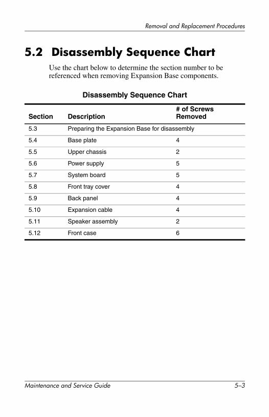
5.2 Disassembly Sequence ChartUse the chart below to determine the section number to be referenced when removing Expansion Base components.
Disassembly Sequence Chart
Section Description# of Screws Removed
5.3 Preparing the Expansion Base for disassembly
5.4 Base plate 4
5.5 Upper chassis 2
5.6 Power supply 5
5.7 System board 5
5.8 Front tray cover 4
5.9 Back panel 4
5.10 Expansion cable 4
5.11 Speaker assembly 2
5.12 Front case 6
Maintenance and Service Guide 5–3

Removal and Replacement Procedures
5.3 Preparing the HP Notebook Expansion Base for DisassemblyPerform the following steps before disassembling the Expansion Base:
1. If the notebook computer is in the Expansion Base,turn off the notebook and press the buttons on the end of the expansion cable 1 to disconnect the cable from the notebook 2.
2. Disconnect the AC adapter and all external devices.
✎ The location of the expansion connector on the notebook may vary by notebook series and model.
Disconnecting the expansion cable
5–4 Maintenance and Service Guide
Removal and Replacement Procedures
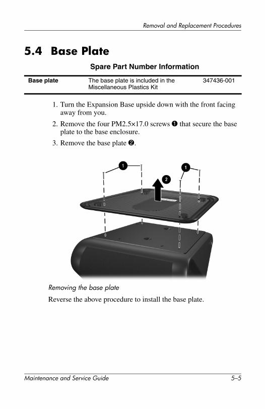
5.4 Base PlateSpare Part Number Information
1. Turn the Expansion Base upside down with the front facing away from you.
2. Remove the four PM2.5×17.0 screws 1 that secure the base plate to the base enclosure.
3. Remove the base plate 2.
Removing the base plate
Reverse the above procedure to install the base plate.
Base plate The base plate is included in the Miscellaneous Plastics Kit
347436-001
Maintenance and Service Guide 5–5

Removal and Replacement Procedures
5.5 Upper Chassis1. Prepare the Expansion Base for disassembly (Section 5.3).
2. Remove the base plate (Section 5.4).
3. Turn the Expansion Base right-side up with the rear panel facing you.
4. Remove the adhesive-backed 8.0-mm diameter screw covers 1.
5. Remove the two PM2.0×6.0 screws 2 that secure the rear cover to the base enclosure.
Removing the rear cover screws
5–6 Maintenance and Service Guide

Removal and Replacement Procedures
6. Lift the front edge of the rear cover up 1 until it disengages from the base enclosure.
7. Slide the rear cover toward you 2 and remove it.
Removing the rear cover
Maintenance and Service Guide 5–7

Removal and Replacement Procedures
8. Disconnect the following cables from the system board:
1 4-wire cable
2 2-wire RJ-11 modem cable
3 50-pin cable
4 6-wire cable
5 4-wire power cable
Disconnecting the cables from the system board
5–8 Maintenance and Service Guide
Removal and Replacement Procedures
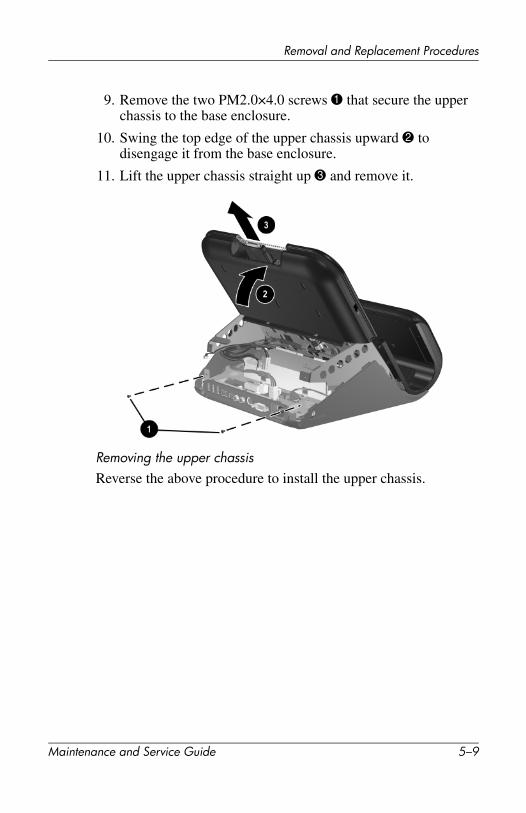
9. Remove the two PM2.0×4.0 screws 1 that secure the upper chassis to the base enclosure.
10. Swing the top edge of the upper chassis upward 2 to disengage it from the base enclosure.
11. Lift the upper chassis straight up 3 and remove it.
Removing the upper chassisReverse the above procedure to install the upper chassis.
Maintenance and Service Guide 5–9

Removal and Replacement Procedures
5.6 Power Supply
1. Prepare the Expansion Base for disassembly (Section 5.3).
2. Remove the base plate (Section 5.4).
3. Remove the upper chassis (Section 5.5).
4. Turn the base enclosure upside down with the front facing you.
5. While holding the power supply in place with one hand underneath, remove the five PM2.0×6.0 screws that secure the power supply to the base enclosure.
Removing the power supply screws
Spare Part Number Information
Power supply 347438-001
5–10 Maintenance and Service Guide

Removal and Replacement Procedures
6. Turn the base enclosure right-side up with the rear facing you.
7. On the base enclosure, disconnect the power supply cable 1 from the system board.
8. Lift the power supply and shield approximately one inch 2.
9. While holding the power supply and shield, remove the power connector 3 from the supports in the base enclosure.
Removing the power supply
Reverse the above procedure to install the power supply.
Maintenance and Service Guide 5–11

Removal and Replacement Procedures
5.7 System Board
1. Prepare the Expansion Base for disassembly (Section 5.3).
2. Remove the base plate (Section 5.4).
3. Remove the upper chassis (Section 5.5).
4. Remove the power supply (Section 5.6).
5. Position the base enclosure with the rear panel facing you.
6. Remove the three PM2.0×6.0 screws 1 that secure the system board to the base enclosure.
7. Use a 5.0-mm hex socket to remove the two HM5.0x9.0 standoffs 2 on either side of the serial connector.
Removing the system board screws and standoffs
Spare Part Number Information
System board 347437-001
5–12 Maintenance and Service Guide

Removal and Replacement Procedures
8. Swing the top left edge of the system board clockwise 1 until the audio connector 2 disengages from the hole 3 in the base enclosure.
9. Remove the system board from the base enclosure 4.
Removing the system board
Reverse the above procedure to install the system board.
Maintenance and Service Guide 5–13
Removal and Replacement Procedures
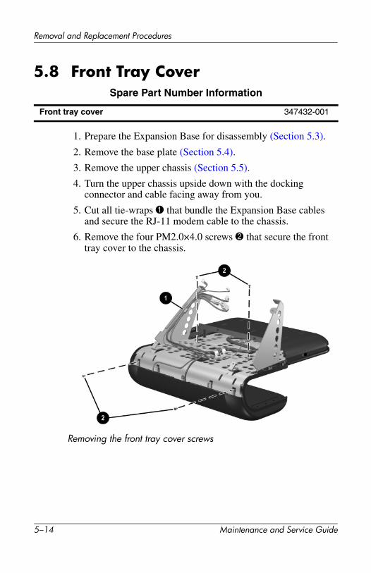
5.8 Front Tray Cover
1. Prepare the Expansion Base for disassembly (Section 5.3).
2. Remove the base plate (Section 5.4).
3. Remove the upper chassis (Section 5.5).
4. Turn the upper chassis upside down with the docking connector and cable facing away from you.
5. Cut all tie-wraps 1 that bundle the Expansion Base cables and secure the RJ-11 modem cable to the chassis.
6. Remove the four PM2.0×4.0 screws 2 that secure the front tray cover to the chassis.
Removing the front tray cover screws
Spare Part Number Information
Front tray cover 347432-001
5–14 Maintenance and Service Guide
Removal and Replacement Procedures
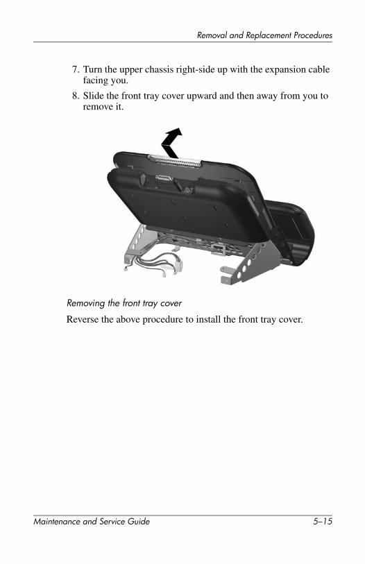
7. Turn the upper chassis right-side up with the expansion cable facing you.
8. Slide the front tray cover upward and then away from you to remove it.
Removing the front tray cover
Reverse the above procedure to install the front tray cover.
Maintenance and Service Guide 5–15

Removal and Replacement Procedures
5.9 Back Panel
1. Prepare the Expansion Base for disassembly (Section 5.3).
2. Remove the base plate (Section 5.4).
3. Remove the upper chassis (Section 5.5).
4. Remove the front tray cover (Section 5.8).
5. Position the upper chassis right-side up with the speakers facing you.
✎ Make sure that the back panel is supported before performing the following steps.
6. Remove the four PM2.0×4.0 screws 1 that secure the back panel to the chassis.
7. Remove the back panel with the RJ-11 cable attached 2.
Removing the back panel
Reverse the above procedure to install the back panel.
Spare Part Number Information
Back panel with RJ-11 cable 347433-001
5–16 Maintenance and Service Guide

Removal and Replacement Procedures
5.10 Expansion Cable
1. Prepare the Expansion Base for disassembly (Section 5.3).
2. Remove the base plate (Section 5.4).
3. Remove the upper chassis (Section 5.5).
4. Remove the front tray cover (Section 5.8).
5. Remove the back panel (Section 5.9).
6. Turn the upper chassis right-side up with the rear facing you. Rotate the chassis so that the expansion cable connector is facing away from you.
7. Remove the four PM2.0×2.0 screws 1 that secure the expansion cable clamps to the chassis.
8. Remove the expansion cable clamps 2 and the expansion cable 3.
Removing the expansion cable clamps and expansion cable
Reverse the above procedure to install the expansion cable.
Spare Part Number Information
Expansion cable 347435-001
Maintenance and Service Guide 5–17

Removal and Replacement Procedures
5.11 Speaker Assembly
1. Prepare the Expansion Base for disassembly (Section 5.3).
2. Remove the base plate (Section 5.4).
3. Remove the upper chassis (Section 5.5).
4. Remove the front tray cover (Section 5.8).
✎ Although the back panel and expansion cable are not shown in the figure, it is not necessary to remove them.
5. Turn the upper chassis upside down, with the bottom facing you and the speaker assembly facing down.
6. Remove the 6-wire audio control cable 1 and the 4-wire speaker cable 2 from the chassis hole through which they are routed.
7. Remove the two PM2.0×4.0 screws 3 that secure the speaker assembly to the chassis.
Removing the speaker assembly screws
Spare Part Number Information
Speaker assembly 347431-001
5–18 Maintenance and Service Guide

Removal and Replacement Procedures
8. Rotate the chassis 180 degrees toward you.
9. Slide the speaker assembly away from you 1 to disengage it from the chassis.
10. Lift the edge of the speaker assembly to remove it from the chassis 2.
Removing the speaker assembly
Reverse the above procedure to install the speaker assembly.
Maintenance and Service Guide 5–19

Removal and Replacement Procedures
5.12 Front Case
1. Prepare the Expansion Base for disassembly (Section 5.3).
2. Remove the base plate (Section 5.4).
3. Remove the upper chassis (Section 5.5).
4. Remove the front tray cover (Section 5.8).
5. Remove the speaker assembly (Section 5.11).
6. Turn the chassis right-side up with the rear facing you. Rotate the top of the chassis toward you.
7. Remove the six PM2.0×5.0 screws 1 that secure the upper chassis front case to the chassis.
8. Slide the front case toward you 2 to disengage it from the chassis.
9. Remove the front case 3 from the chassis.
Removing the front case
Reverse the above procedure to install the front case.
Spare Part Number Information
Front case (plastics kit) 347436-001
Upper chassis 347434-001
5–20 Maintenance and Service Guide

6Specifications
This chapter provides physical and performance specifications.
Table 6-1HP Notebook Expansion Base
Dimensions
HeightWidthDepth
22.8 cm31.8 cm29.8 cm
9 in12.5 in11.75 in
Weight
3.5 kg 7.5 lb
Stand-alone power requirements
Power supply 18.5 V at 8 amps
Temperature
Operating (not writing optical)Operating (writing optical)Nonoperating
0°C to 35°C
5°C to 35°C
-20°C to 60°C
32°F to 95°F
41°F to 95°F
-4°F to 140°F
✎ Applicable product safety standards specify thermal limits for plastic surfaces. The notebook operates well within this range of temperatures.
Relative humidity (noncondensing)
OperatingNonoperating
10% to 90%5% to 95%, 38.7°C (101.6°F) maximum wet bulb temperature
Maintenance and Service Guide 6–1
Specifications
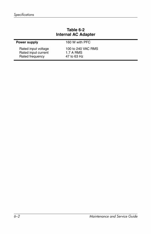
Table 6-2Internal AC Adapter
Power supply 160 W with PFC
Rated input voltageRated input currentRated frequency
100 to 240 VAC RMS1.7 A RMS47 to 63 Hz
6–2 Maintenance and Service Guide
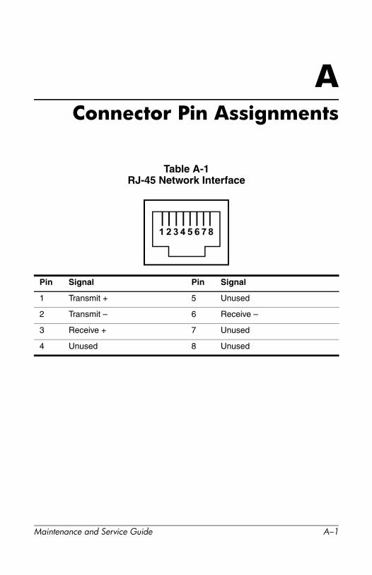
AConnector Pin Assignments
Table A-1RJ-45 Network Interface
Pin Signal Pin Signal
1 Transmit + 5 Unused
2 Transmit – 6 Receive –
3 Receive + 7 Unused
4 Unused 8 Unused
Maintenance and Service Guide A–1

Connector Pin Assignments
Table A-2RJ-11 Modem
Pin Signal Pin Signal
1 Unused 4 Unused
2 Tip 5 Unused
3 Ring 6 Unused
Table A-3Universal Serial Bus
Pin Signal Pin Signal
1 +5 VDC 3 Data +
2 Data – 4 Ground
A–2 Maintenance and Service Guide
Connector Pin Assignments
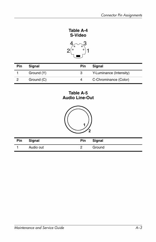
Table A-4S-Video
Pin Signal Pin Signal
1 Ground (Y) 3 Y-Luminance (Intensity)
2 Ground (C) 4 C-Chrominance (Color)
Table A-5Audio Line-Out
Pin Signal Pin Signal
1 Audio out 2 Ground
124 3
Maintenance and Service Guide A–3

Connector Pin Assignments
Table A-6Serial
Pin Signal Pin Signal
1 Carrier detect 6 Data set ready
2 Receive data 7 Ready to send
3 Transmit data 8 Clear to send
4 Data terminal ready 9 Ring indicator
5 Ground
A–4 Maintenance and Service Guide

Connector Pin Assignments
Maintenance and Service Guide A–5
Table A-7S/PDIF Audio Line-Out
Table A-8Video
Pin Signal Pin Signal
1 Audio signal 2 Ground/return
Pin Signal Pin Signal
1 Video signal 2 Ground/return
1 2
1 2

BPower Cord Set Requirements
3-Conductor Power Cord SetThe wide range input feature of the notebook permits it to operate from any line voltage from 100 to 120 or 220 to 240 volts AC.
The power cord set shipped with the notebook meets the requirements for use in the country where the equipment is purchased.
Power cord sets for use in other countries must meet the requirements of the country where the notebook is used.
General RequirementsThe requirements listed below are applicable to all countries:
■ The length of the power cord set must be at least 1.5 meters (5.00 feet) and a maximum of 2.0 meters (6.50 feet).
■ All power cord sets must be approved by an acceptable accredited agency responsible for evaluation in the country where the power cord set will be used.
■ The power cord set must have a minimum current capacity of 10 amps and a nominal voltage rating of 125 or 250 volts AC, as required by each country’s power system.
■ The appliance coupler must meet the mechanical configuration of an EN 60 320/IEC 320 Standard Sheet C13 connector for mating with the appliance inlet on the back of the notebook.
Maintenance and Service Guide B–1

Power Cord Set Requirements
Country-Specific Requirements3-Conductor Power Cord Set Requirements
Country Accredited AgencyApplicable Note Number
Australia EANSW 1
Austria OVE 1
Belgium CEBC 1
Canada CSA 2
Denmark DEMKO 1
Finland FIMKO 1
France UTE 1
Germany VDE 1
Italy IMQ 1
Japan METI 3
The Netherlands KEMA 1
Norway NEMKO 1
Sweden SEMKO 1
Switzerland SEV 1
B–2 Maintenance and Service Guide
Power Cord Set Requirements
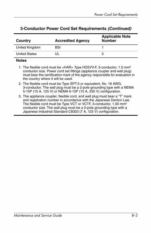
United Kingdom BSI 1
United States UL 2
Notes
1. The flexible cord must be <HAR> Type HO5VV-F, 3-conductor, 1.0 mm²
conductor size. Power cord set fittings (appliance coupler and wall plug) must bear the certification mark of the agency responsible for evaluation in the country where it will be used.
2. The flexible cord must be Type SPT-3 or equivalent, No. 18 AWG, 3-conductor. The wall plug must be a 2-pole grounding type with a NEMA 5-15P (15 A, 125 V) or NEMA 6-15P (15 A, 250 V) configuration.
3. The appliance coupler, flexible cord, and wall plug must bear a “T” mark and registration number in accordance with the Japanese Dentori Law. The flexible cord must be Type VCT or VCTF, 3-conductor, 1.00 mm²
conductor size. The wall plug must be a 2-pole grounding type with a Japanese Industrial Standard C8303 (7 A, 125 V) configuration.
3-Conductor Power Cord Set Requirements (Continued)
Country Accredited AgencyApplicable Note Number
Maintenance and Service Guide B–3
CScrew Listing
This appendix provides specification and reference information for the screws used in the HP Notebook Expansion Base. All screws listed in this appendix are available in the Miscellaneous Screw Kit, spare part number 347439-001.
Maintenance and Service Guide C–1

Screw Listing
Phillips M2.5×17.0 screw locations
Table C-1Phillips PM2.5×17.0 Screw
Color Qty. Length ThreadHead Width
Bronze 4 17.0 mm 2.5 mm 6.0 mm
Where used:Four screws that secure the base plate to the base enclosure(documented in Section 5.4)
mm
C–2 Maintenance and Service Guide
Screw Listing
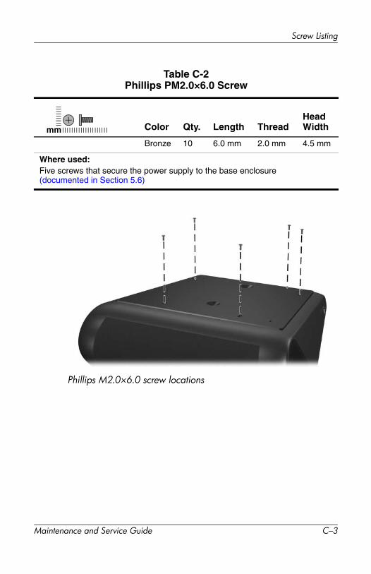
Phillips M2.0×6.0 screw locations
Table C-2Phillips PM2.0×6.0 Screw
Color Qty. Length ThreadHead Width
Bronze 10 6.0 mm 2.0 mm 4.5 mm
Where used:Five screws that secure the power supply to the base enclosure(documented in Section 5.6)
mm
Maintenance and Service Guide C–3

Screw Listing
Phillips M2.0×6.0 screw locations
Table C-2Phillips PM2.0×6.0 Screw (Continued)
Color Qty. Length ThreadHead Width
Bronze 10 6.0 mm 2.0 mm 4.5 mm
Where used:Two screws that secure the rear cover to the base enclosure (documented in Section 5.5)
mm
C–4 Maintenance and Service Guide

Screw Listing
Table C-2Phillips PM2.0×6.0 Screw (Continued)
Phillips M2.0×6.0 screw locations
Color Qty. Length ThreadHead Width
Bronze 10 6.0 mm 2.0 mm 4.5 mm
Where used:Three screws that secure the system board to the base enclosure (documented in Section 5.7)
mm
Maintenance and Service Guide C–5

Screw Listing
HM5.0×9.0 screw locations
Table C-4HM5.0×9.0 Standoff
Color Qty. Length ThreadHead Width
Silver 2 9.0 mm 5.0 mm 5.0 mm
Where used:Two standoffs that secure the system board to the base enclosure(documented in Section 5.7)
mm
C–6 Maintenance and Service Guide

Screw Listing
Phillips M2.0×4.0 screw locations
Table C-5Phillips PM2.0×4.0 Screw
Color Qty. Length ThreadHead Width
Bronze 18 4.0 mm 2.0 mm 4.0 mm
Where used:Two screws that secure the upper chassis to the base enclosure(documented in Section 5.5)
mm
Maintenance and Service Guide C–7

Screw Listing
Phillips M2.0x4.0 screw locations
Table C-5Phillips PM2.0x4.0 Screw (Continued)
Color Qty. Length ThreadHead Width
Bronze 18 4.0 mm 2.0 mm 4.0 mm
Where used:Four screws that secure the front tray cover to the upper chassis(documented in Section 5.8)
mm
C–8 Maintenance and Service Guide

Screw Listing
Phillips M2.0x4.0 screw locations
Table C-5Phillips PM2.0×4.0 Screw (Continued)
Color Qty. Length ThreadHead Width
Bronze 18 4.0 mm 2.0 mm 4.0 mm
Where used:Four screws that secure the back panel to the chassis(documented in Section 5.9)
mm
Maintenance and Service Guide C–9

Screw Listing
Phillips M2.0x4.0 screw locations
Table C-5Phillips PM2.0×4.0 Screw (Continued)
Color Qty. Length ThreadHead Width
Bronze 18 4.0 mm 2.0 mm 4.0 mm
Where used:Two screws that secure the speaker assembly to the chassis(documented in Section 5.11)
mm
C–10 Maintenance and Service Guide

Screw Listing
Phillips M2.0x4.0 screw locations
Table C-5Phillips PM2.0×4.0 Screw (Continued)
Color Qty. Length ThreadHead Width
Bronze 18 4.0 mm 2.0 mm 4.0 mm
Where used:Six screws that secure the front case to the chassis(documented in Section 5.12)
mm
Maintenance and Service Guide C–11

Screw Listing
Phillips M2.0x2.0 screw locations
Table C-6Phillips PM2.0×2.0 Screw
Color Qty. Length ThreadHead Width
Silver 4 2.0 mm 2.0 mm 8 mm
Where used:Four screws that secure the expansion cable brackets to the chassis (documented in Section 5.10)
mm
C–12 Maintenance and Service Guide

Index
AAC adapter specifications 6–2audio line-out pin assignments
A–3
Bback panel
removal 5–16spare part number 3–3
base enclosure, spare part number 3–3
base plateremoval 5–5spare part number 3–3
Ccables, service considerations 4–2components
front 1–3left-side 1–5rear 1–5right-side 1–3, 1–5
composite jack 1–7connection indicator light 1–4connector pin assignments
audio line-out A–3modem jack A–2network jack A–1RJ-11 telephone jack A–2
RJ-45 network jack A–1S/PDIF audio line-out jack A–5serial connector A–4S-Video connector A–3USB connectors A–2
connectors, service considerations 4–2
Ddesign overview 1–10disassembly sequence chart 5–3
Eelectrostatic discharge 4–2, 4–6expansion base specifications 6–1expansion cable 1–4, 1–7
disconnecting 5–4removal 5–17spare part number 3–3
Ffeatures 1–2front case
removal 5–20spare part number 3–3
front components 1–3front tray cover
removal 5–14spare part number 3–3
Maintenance and Service Guide Index–1

Index
Ggrounding equipment and methods
4–5
Hheadphone jack 1–5
Kkeyboard, wireless 1–9
Lleft-side components 1–5
MMiscellaneous Plastics Kit, spare
part number 3–3modem jack, pin assignments A–2mouse, wireless 1–9mute button 1–4
Nnetwork jack, pin assignments A–1
Ppacking precautions 4–3plastic parts 4–2power connector 1–7power cord set requirements B–1power cord, spare part numbers
3–6power supply
removal 5–10spare part number 3–3
Rrear components 1–5rear cover
removal 5–6spare part number 3–3
receiverfunction 1–9spare part number 3–5
removal preliminaries 4–1replacement preliminaries 4–1right-side components 1–3, 1–5RJ-11 telephone jack
location 1–7pin assignments A–2
RJ-45 network jacklocation 1–7pin assignments A–1
SS/PDIF audio line-out jack
pin assignments A–5S/PDIF connector location 1–7screw listing C–1security cable slot 1–5, 1–8serial connector
location 1–7pin assignments A–4
serial number 3–1, 5–2service considerations 4–1speaker assembly
location 1–4removal 5–18spare part number 3–3
specificationsAC adapter 6–2expansion base 6–1
static shielding materials 4–6S-Video connector
location 1–7pin assignments A–3
Index–2 Maintenance and Service Guide

Index
system boardremoval 5–12spare part number 3–3
system board cables, removal 5–8
Ttools required 4–1transporting precautions 4–3troubleshooting 2–1
problems and solutions 2–2TV out, location 1–7
Uupper chassis
removal 5–6spare part number 3–3
USB connectorslocation 1–5, 1–7pin assignments A–2
Vvent 1–5, 1–7, 1–8volume down button 1–4volume up button 1–4
Wwireless accessories 1–9wireless keyboard 1–9
spare part numbers 3–5wireless mouse 1–9
spare part number 3–5workstation precautions 4–4
Maintenance and Service Guide Index–3