Embed Size (px)
Citation preview
HP Pavilion dv7 Notebook PC
Maintenance and Service Guide
© Copyright 2011 Hewlett-PackardDevelopment Company, L.P.
AMD, the AMD Arrow logo, Athlon,Phenom, Sempron, Turion, andcombinations thereof, are trademarks ofAdvanced Micro Devices, Inc. Bluetooth is atrademark owned by its proprietor and usedby Hewlett-Packard Company under license.Intel, Celeron, Core, and Pentium aretrademarks of Intel Corporation in the U.S.and other countries. Microsoft and Windowsare U.S. registered trademarks of MicrosoftCorporation. SD Logo is a trademark ofits proprietor.
The information contained herein is subjectto change without notice. The onlywarranties for HP products and services areset forth in the express warranty statementsaccompanying such products and services.Nothing herein should be construed asconstituting an additional warranty. HP shallnot be liable for technical or editorial errorsor omissions contained herein.
Second Edition: May 2011
First Edition: January 2011
Document Part Number: 635468-003

Safety warning notice
WARNING! To reduce the possibility of heat-related injuries or of overheating the device, do notplace the device directly on your lap or obstruct the device air vents. Use the device only on a hard, flatsurface. Do not allow another hard surface, such as an adjoining optional printer, or a soft surface,such as pillows or rugs or clothing, to block airflow. Also, do not allow the AC adapter to contact theskin or a soft surface, such as pillows or rugs or clothing, during operation. The device and the ACadapter comply with the user-accessible surface temperature limits defined by the InternationalStandard for Safety of Information Technology Equipment (IEC 60950).
iii

iv Safety warning notice
Table of contents
1 Product description ........................................................................................................... 1
2 External component identification ................................................................................... 11
Top ...................................................................................................................................... 12Buttons ................................................................................................................... 12Keys ...................................................................................................................... 13Lights ..................................................................................................................... 15TouchPad ............................................................................................................... 16
Display ................................................................................................................................. 17Front ..................................................................................................................................... 18Left side ................................................................................................................................ 19Right side .............................................................................................................................. 20Bottom .................................................................................................................................. 21
3 Illustrated parts catalog .................................................................................................. 22
Service tag ............................................................................................................................ 23Computer major components ................................................................................................... 24Display assembly subcomponents ............................................................................................. 33Mass storage devices ............................................................................................................. 34Miscellaneous parts ................................................................................................................ 35Sequential part number listing .................................................................................................. 36
4 Removal and replacement procedures ............................................................................ 46
Preliminary replacement requirements ....................................................................................... 46Tools required ......................................................................................................... 46Service considerations ............................................................................................. 46
Plastic parts ............................................................................................. 46Cables and connectors ............................................................................. 46Drive handling ......................................................................................... 47
Grounding guidelines .............................................................................................. 47Electrostatic discharge damage .................................................................. 47
v
Packaging and transporting guidelines ........................................ 49Component replacement procedures ........................................................................................ 51
Service tag ............................................................................................................. 51Computer feet ......................................................................................................... 52Battery ................................................................................................................... 52Optical drive .......................................................................................................... 53Hard drive ............................................................................................................. 56RTC battery ............................................................................................................ 60Memory module ...................................................................................................... 61WLAN module ........................................................................................................ 62Keyboard ............................................................................................................... 65Top cover ............................................................................................................... 68Fingerprint reader board .......................................................................................... 72Power button board ................................................................................................. 74Display lid switch board .......................................................................................... 76SD Card reader board ............................................................................................. 78Bluetooth module .................................................................................................... 80USB board ............................................................................................................. 82Front speakers ........................................................................................................ 84Power connector cable ............................................................................................ 86System board ......................................................................................................... 87Fan/heat sink assembly ........................................................................................... 91Processor ............................................................................................................... 95Optical drive cable ................................................................................................. 99Rear speakers ....................................................................................................... 100Subwoofer ........................................................................................................... 102Display assembly .................................................................................................. 103
5 Setup Utility (BIOS) and System Diagnostics .................................................................. 111
Using Setup Utility ................................................................................................................ 111Starting Setup Utility .............................................................................................. 111Changing the language of Setup Utility .................................................................... 111Navigating and selecting in Setup Utility .................................................................. 112Displaying system information ................................................................................. 112Restoring factory settings in Setup Utility ................................................................... 113Exiting Setup Utility ............................................................................................... 113Updating the BIOS ................................................................................................ 113
Determining the BIOS version .................................................................. 114Downloading a BIOS update ................................................................... 114
Using System Diagnostics ...................................................................................................... 115
vi
6 Specifications ............................................................................................................... 116
Device specifications ............................................................................................................ 11617.3-inch display specifications ............................................................................................. 117Hard drive specifications ...................................................................................................... 118
7 Backup and recovery .................................................................................................... 119
Restore ............................................................................................................................... 119Creating restore media ......................................................................................................... 120Performing a system restore ................................................................................................... 121
Restoring using the dedicated recovery partition (select models only) ........................... 121Restoring using the restore media ............................................................................ 122Changing the computer boot order .......................................................................... 122
Backing up and recovering your information ........................................................................... 123Using Windows Backup and Restore ....................................................................... 124Using Windows system restore points ...................................................................... 124
When to create restore points .................................................................. 124Create a system restore point ................................................................... 125Restore to a previous date and time .......................................................... 125
8 Power cord set requirements ........................................................................................ 126
Requirements for all countries ................................................................................................ 126Requirements for specific countries and regions ....................................................................... 127
9 Recycling ...................................................................................................................... 128
Battery ................................................................................................................................ 128Display ............................................................................................................................... 128
Index ............................................................................................................................... 134
vii

viii
1 Product description
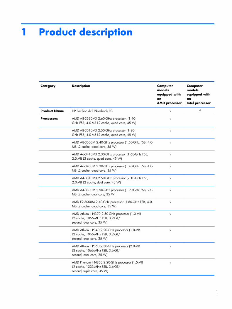
Category Description Computermodelsequipped withanAMD processor
Computermodelsequipped withanIntel processor
Product Name HP Pavilion dv7 Notebook PC √ √
Processors AMD A8-3530MX 2.60-GHz processor, (1.90-GHz FSB, 4.0-MB L2 cache, quad core, 45 W)
√
AMD A8-3510MX 2.50-GHz processor (1.80-GHz FSB, 4.0-MB L2 cache, quad core, 45 W)
√
AMD A8-3500M 2.40-GHz processor (1.50-GHz FSB, 4.0-MB L2 cache, quad core, 35 W)
√
AMD A6-3410MX 2.30-GHz processor (1.60-GHz FSB,2.0-MB L2 cache, quad core, 45 W)
√
AMD A6-3400M 2.30-GHz processor (1.40-GHz FSB, 4.0-MB L2 cache, quad core, 35 W)
√
AMD A4-3310MX 2.50-GHz processor (2.10-GHz FSB,2.0-MB L2 cache, dual core, 45 W)
√
AMD A4-3300M 2.50-GHz processor (1.90-GHz FSB, 2.0-MB L2 cache, dual core, 35 W)
√
AMD E2-3000M 2.40-GHz processor (1.80-GHz FSB, 4.0-MB L2 cache, quad core, 35 W)
√
AMD Athlon II N370 2.50-GHz processor (1.0-MBL2 cache, 1066-MHz FSB, 3.2-GT/second, dual core, 35 W)
√
AMD Athlon II P340 2.20-GHz processor (1.0-MBL2 cache, 1066-MHz FSB, 3.2-GT/second, dual core, 25 W)
√
AMD Athlon II P360 2.30-GHz processor (2.0-MBL2 cache, 1066-MHz FSB, 3.6-GT/second, dual core, 25 W)
√
AMD Phenom II N850 2.20-GHz processor (1.5-MBL2 cache, 1333-MHz FSB, 3.6-GT/second, triple core, 35 W)
√
1
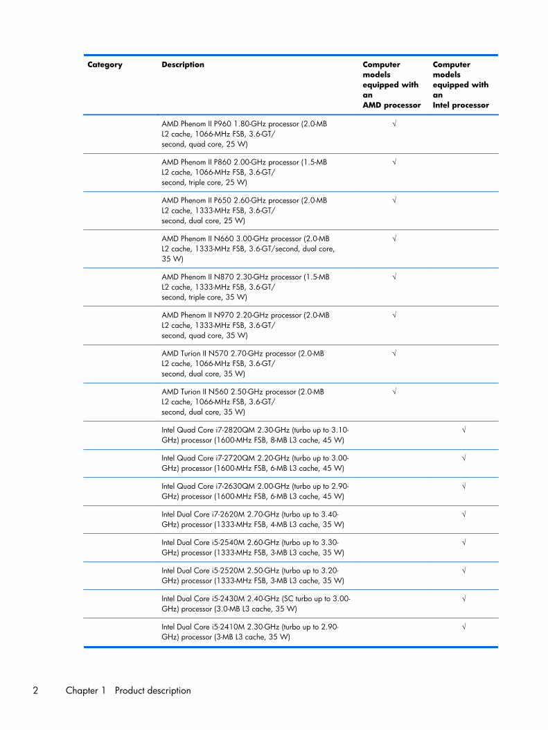
Category Description Computermodelsequipped withanAMD processor
Computermodelsequipped withanIntel processor
AMD Phenom II P960 1.80-GHz processor (2.0-MBL2 cache, 1066-MHz FSB, 3.6-GT/second, quad core, 25 W)
√
AMD Phenom II P860 2.00-GHz processor (1.5-MBL2 cache, 1066-MHz FSB, 3.6-GT/second, triple core, 25 W)
√
AMD Phenom II P650 2.60-GHz processor (2.0-MBL2 cache, 1333-MHz FSB, 3.6-GT/second, dual core, 25 W)
√
AMD Phenom II N660 3.00-GHz processor (2.0-MBL2 cache, 1333-MHz FSB, 3.6-GT/second, dual core,35 W)
√
AMD Phenom II N870 2.30-GHz processor (1.5-MBL2 cache, 1333-MHz FSB, 3.6-GT/second, triple core, 35 W)
√
AMD Phenom II N970 2.20-GHz processor (2.0-MBL2 cache, 1333-MHz FSB, 3.6-GT/second, quad core, 35 W)
√
AMD Turion II N570 2.70-GHz processor (2.0-MBL2 cache, 1066-MHz FSB, 3.6-GT/second, dual core, 35 W)
√
AMD Turion II N560 2.50-GHz processor (2.0-MBL2 cache, 1066-MHz FSB, 3.6-GT/second, dual core, 35 W)
√
Intel Quad Core i7-2820QM 2.30-GHz (turbo up to 3.10-GHz) processor (1600-MHz FSB, 8-MB L3 cache, 45 W)
√
Intel Quad Core i7-2720QM 2.20-GHz (turbo up to 3.00-GHz) processor (1600-MHz FSB, 6-MB L3 cache, 45 W)
√
Intel Quad Core i7-2630QM 2.00-GHz (turbo up to 2.90-GHz) processor (1600-MHz FSB, 6-MB L3 cache, 45 W)
√
Intel Dual Core i7-2620M 2.70-GHz (turbo up to 3.40-GHz) processor (1333-MHz FSB, 4-MB L3 cache, 35 W)
√
Intel Dual Core i5-2540M 2.60-GHz (turbo up to 3.30-GHz) processor (1333-MHz FSB, 3-MB L3 cache, 35 W)
√
Intel Dual Core i5-2520M 2.50-GHz (turbo up to 3.20-GHz) processor (1333-MHz FSB, 3-MB L3 cache, 35 W)
√
Intel Dual Core i5-2430M 2.40-GHz (SC turbo up to 3.00-GHz) processor (3.0-MB L3 cache, 35 W)
√
Intel Dual Core i5-2410M 2.30-GHz (turbo up to 2.90-GHz) processor (3-MB L3 cache, 35 W)
√
2 Chapter 1 Product description
Category Description Computermodelsequipped withanAMD processor
Computermodelsequipped withanIntel processor
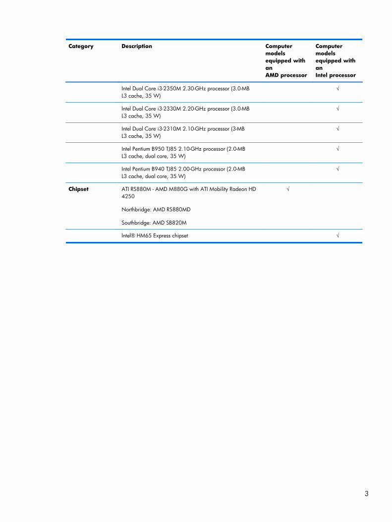
Intel Dual Core i3-2350M 2.30-GHz processor (3.0-MBL3 cache, 35 W)
√
Intel Dual Core i3-2330M 2.20-GHz processor (3.0-MBL3 cache, 35 W)
√
Intel Dual Core i3-2310M 2.10-GHz processor (3-MBL3 cache, 35 W)
√
Intel Pentium B950 TJ85 2.10-GHz processor (2.0-MBL3 cache, dual core, 35 W)
√
Intel Pentium B940 TJ85 2.00-GHz processor (2.0-MBL3 cache, dual core, 35 W)
√
Chipset ATI RS880M - AMD M880G with ATI Mobility Radeon HD4250
Northbridge: AMD RS880MD
Southbridge: AMD SB820M
√
Intel® HM65 Express chipset √
3
Category Description Computermodelsequipped withanAMD processor
Computermodelsequipped withanIntel processor
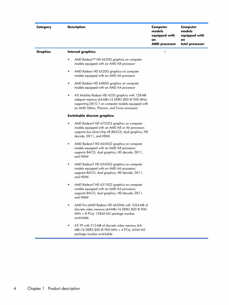
Graphics Internal graphics:
● AMD Radeon™ HD 6620G graphics on computermodels equipped with an AMD A8 processor
● AMD Radeon HD 6520G graphics on computermodels equipped with an AMD A6 processor
● AMD Radeon HD 6480G graphics on computermodels equipped with an AMD A4 processor
● ATI Mobility Radeon HD 4250 graphics with 128-MBsideport memory (64-MB×16 DDR3 800 @ 900 MHz)supporting DX10.1 on computer models equipped withan AMD Athlon, Phenom, and Turion processor
Switchable discrete graphics:
● AMD RadeonT HD 6755G2 graphics on computermodels equipped with an AMD A8 or A6 processor;supports bus alive/chip off (BACO), dual graphics, HDdecode, DX11, and HDMI
● AMD RadeonT HD 6645G2 graphics on computermodels equipped with an AMD A8 processor;supports BACO, dual graphics, HD decode, DX11,and HDMI
● AMD RadeonT HD 6545G2 graphics on computermodels equipped with an AMD A6 processor;supports BACO, dual graphics, HD decode, DX11,and HDMI
● AMD RadeonT HD 6515G2 graphics on computermodels equipped with an AMD A4 processor;supports BACO, dual graphics, HD decode, DX11,and HDMI
● AMD Pro (AMD Radeon HD 6650M) with 1024-MB ofdiscrete video memory (64-MB×16 DDR3 800 @ 900MHz × 8 PCs); 128-bit M2 package muxlessswitchable
● ATi XT with 512-MB of discrete video memory (64-MB×16 DDR3 800 @ 900 MHz × 4 PCs); 64-bit M2package muxless switchable
√
4 Chapter 1 Product description
Category Description Computermodelsequipped withanAMD processor
Computermodelsequipped withanIntel processor
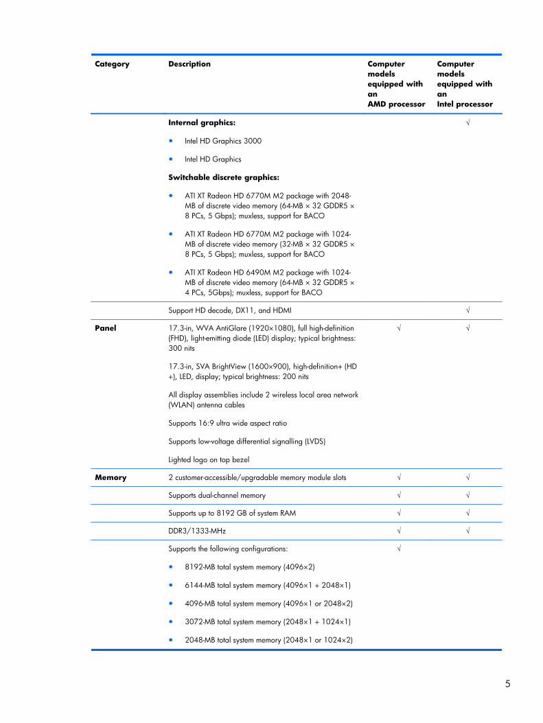
Internal graphics:
● Intel HD Graphics 3000
● Intel HD Graphics
Switchable discrete graphics:
● ATI XT Radeon HD 6770M M2 package with 2048-MB of discrete video memory (64-MB × 32 GDDR5 ×8 PCs, 5 Gbps); muxless, support for BACO
● ATI XT Radeon HD 6770M M2 package with 1024-MB of discrete video memory (32-MB × 32 GDDR5 ×8 PCs, 5 Gbps); muxless, support for BACO
● ATI XT Radeon HD 6490M M2 package with 1024-MB of discrete video memory (64-MB × 32 GDDR5 ×4 PCs, 5Gbps); muxless, support for BACO
√
Support HD decode, DX11, and HDMI √
Panel 17.3-in, WVA AntiGlare (1920×1080), full high-definition(FHD), light-emitting diode (LED) display; typical brightness:300 nits
17.3-in, SVA BrightView (1600×900), high-definition+ (HD+), LED, display; typical brightness: 200 nits
All display assemblies include 2 wireless local area network(WLAN) antenna cables
Supports 16:9 ultra wide aspect ratio
Supports low-voltage differential signalling (LVDS)
Lighted logo on top bezel
√ √
Memory 2 customer-accessible/upgradable memory module slots √ √
Supports dual-channel memory √ √
Supports up to 8192 GB of system RAM √ √
DDR3/1333-MHz √ √
Supports the following configurations:
● 8192-MB total system memory (4096×2)
● 6144-MB total system memory (4096×1 + 2048×1)
● 4096-MB total system memory (4096×1 or 2048×2)
● 3072-MB total system memory (2048×1 + 1024×1)
● 2048-MB total system memory (2048×1 or 1024×2)
√
5
Category Description Computermodelsequipped withanAMD processor
Computermodelsequipped withanIntel processor
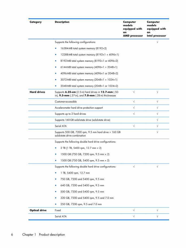
Supports the following configurations:
● 16384-MB total system memory (8192×2)
● 12288-MB total system memory (8192×1 + 4096×1)
● 8192-MB total system memory (8192×1 or 4096×2)
● 6144-MB total system memory (4096×1 + 2048×1)
● 4096-MB total system memory (4096×1 or 2048×2)
● 3072-MB total system memory (2048×1 + 1024×1)
● 2048-MB total system memory (2048×1 or 1024×2)
√
Hard drives Supports 6.35-cm (2.5-in) hard drives in 12.7-mm (.50-in), 9.5-mm (.37-in), and 7.0-mm (.28-in) thicknesses
√ √
Customer-accessible √ √
Accelerometer hard drive protection support √ √
Supports up to 2 hard drives √ √
Supports 160-GB solid-state drive (solid-state drive) √
Serial ATA √ √
Supports 500 GB, 7200 rpm, 9.5 mm hard drive + 160 GBsolid-state drive combination
√
Supports the following double hard drive configurations:
● 2 TB (1 TB, 5400 rpm, 12.7 mm × 2)
● 1500 GB (750 GB, 7200 rpm, 9.5 mm × 2)
● 1500 GB (750 GB, 5400 rpm, 9.5 mm × 2)
Supports the following double hard drive configurations:
● 1 TB, 5400 rpm, 12.7 mm
● 750 GB, 7200 and 5400 rpm, 9.5 mm
● 640 GB, 7200 and 5400 rpm, 9.5 mm
● 500 GB, 7200 and 5400 rpm, 9.5 mm
● 320 GB, 7200 and 5400 rpm, 9.5 and 7.0 mm
● 250 GB, 7200 rpm, 9.5 and 7.0 mm
√ √
Optical drive Fixed √ √
Serial ATA √ √
6 Chapter 1 Product description
Category Description Computermodelsequipped withanAMD processor
Computermodelsequipped withanIntel processor
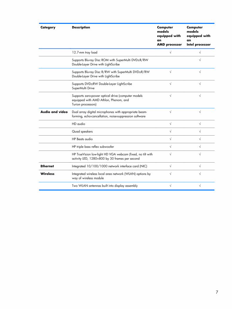
12.7-mm tray load √ √
Supports Blu-ray Disc ROM with SuperMulti DVD±R/RWDouble-Layer Drive with LightScribe
√
Supports Blu-ray Disc R/RW with SuperMulti DVD±R/RWDouble-Layer Drive with LightScribe
√ √
Supports DVD±RW Double-Layer LightScribeSuperMulti Drive
√ √
Supports zero-power optical drive (computer modelsequipped with AMD Athlon, Phenom, andTurion processors)
√ √
Audio and video Dual array digital microphones with appropriate beam-forming, echo-cancellation, noise-suppression software
√ √
HD audio √ √
Quad speakers √ √
HP Beats audio √ √
HP triple bass reflex subwoofer √ √
HP TrueVision low-light HD VGA webcam (fixed, no tilt withactivity LED, 1280×800 by 30 frames per second
√ √
Ethernet Integrated 10/100/1000 network interface card (NIC) √ √
Wireless Integrated wireless local area network (WLAN) options byway of wireless module
√ √
Two WLAN antennas built into display assembly √ √
7

Category Description Computermodelsequipped withanAMD processor
Computermodelsequipped withanIntel processor
Support for the following WLAN formats:
● Atheros 9485GN 802.11b/g/n 1×1 WiFi and 3012Bluetooth 4.0 Combo Adapter
● Atheros AR9285 802.11b/g/n 1×1 WiFi Adapter
● Broadcom 4313 802.11b/g/n 1×1 WiFi Adapter
● Broadcom 4313 802.11b/g/n 1×1 WiFi and 2070Bluetooth 2.1+EDR Combo adapter (BT3.0HS ready)
● Broadcom 4313GN 802.11b/g/n 1×1 WiFi and20702 Bluetooth 4.0 Combo Adapter
● Ralink RT3090BC4 802.11b/g/n 1×1 WiFi andBluetooth 2.1+EDR Combo adapter (BT3.0HS ready)
● Ralink 5390GN 802.11b/g/n 1×1 WiFi Adapter
● Realtek RTL8188CE 802.11b/g/n 1×1 WiFi andBluetooth 4.0LE Combo Adapter
√ √
Support for the following WLAN formats:
● Atheros AR9002WB-1NGB 802.11b/g/n 1×1 WiFiand Bluetooth 2.1EDR+ Combo Adapter(BT3.0+HS ready)
● Realtek 8188BC8 802.11a/b/g/n 2×2 WiFi andBluetooth 3.0+HS Combo Adapter
● Realtek 8188GN 802.11b/g/n 1×1 WiFi Adapter
√
Support for the following WLAN formats:
● Intel Centrino Advanced-N 6230
● Intel Centrino Wireless-N 1000 802.11b/g/n 1×2WLAN module
● Intel Centrino Wireless-N + WiMAX 6150
√
External mediacard
Digital Media Slot supports the following digitalcard formats:
● MultiMediaCard
● Secure Digital (SD) Memory Card
● Secure Digital High Capacity Memory card
● Secure Digital Extended Capacity Memory Card
√ √
HP Multi-Format digital Media Reader support SD/SDHC/SDXC with UHS104 support, MMC push-push insertion andremoval
√ √
8 Chapter 1 Product description
Category Description Computermodelsequipped withanAMD processor
Computermodelsequipped withanIntel processor
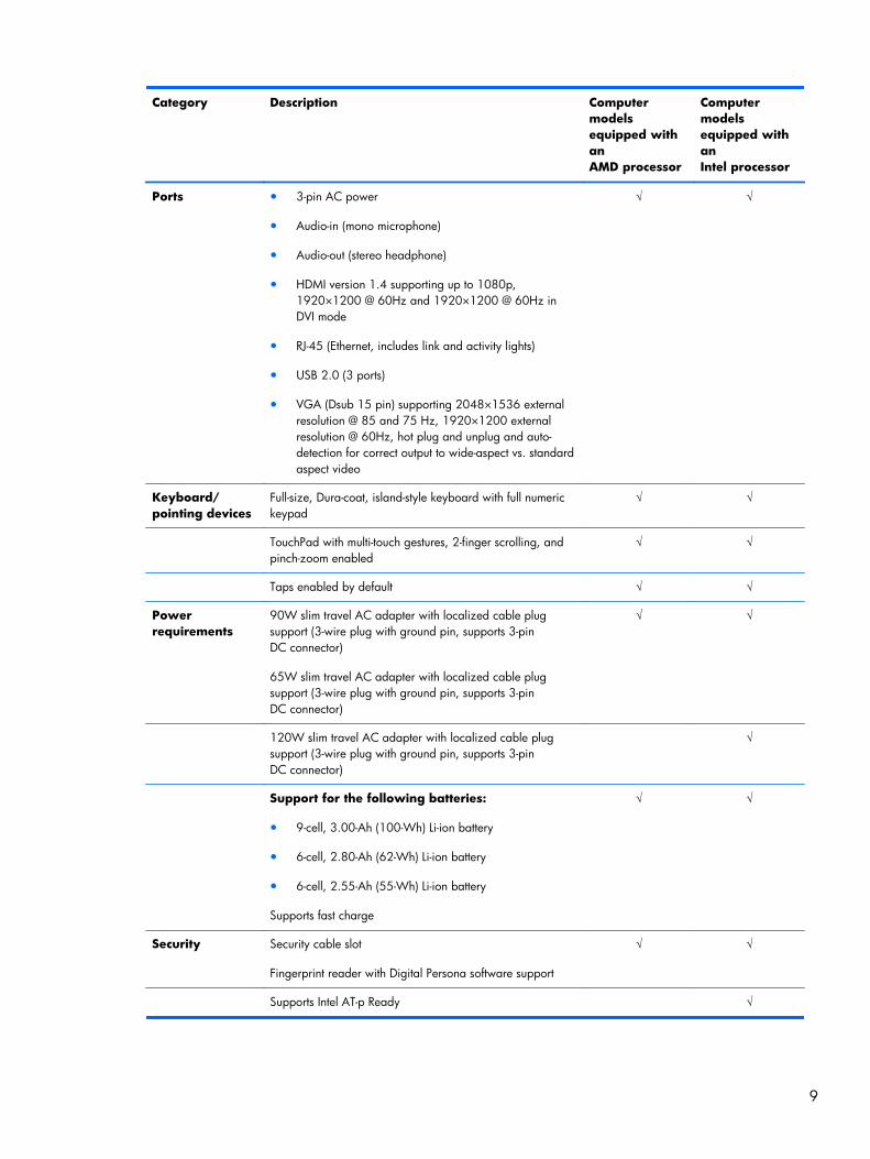
Ports ● 3-pin AC power
● Audio-in (mono microphone)
● Audio-out (stereo headphone)
● HDMI version 1.4 supporting up to 1080p,1920×1200 @ 60Hz and 1920×1200 @ 60Hz inDVI mode
● RJ-45 (Ethernet, includes link and activity lights)
● USB 2.0 (3 ports)
● VGA (Dsub 15 pin) supporting 2048×1536 externalresolution @ 85 and 75 Hz, 1920×1200 externalresolution @ 60Hz, hot plug and unplug and auto-detection for correct output to wide-aspect vs. standardaspect video
√ √
Keyboard/pointing devices
Full-size, Dura-coat, island-style keyboard with full numerickeypad
√ √
TouchPad with multi-touch gestures, 2-finger scrolling, andpinch-zoom enabled
√ √
Taps enabled by default √ √
Powerrequirements
90W slim travel AC adapter with localized cable plugsupport (3-wire plug with ground pin, supports 3-pinDC connector)
65W slim travel AC adapter with localized cable plugsupport (3-wire plug with ground pin, supports 3-pinDC connector)
√ √
120W slim travel AC adapter with localized cable plugsupport (3-wire plug with ground pin, supports 3-pinDC connector)
√
Support for the following batteries:
● 9-cell, 3.00-Ah (100-Wh) Li-ion battery
● 6-cell, 2.80-Ah (62-Wh) Li-ion battery
● 6-cell, 2.55-Ah (55-Wh) Li-ion battery
Supports fast charge
√ √
Security Security cable slot
Fingerprint reader with Digital Persona software support
√ √
Supports Intel AT-p Ready √
9
Category Description Computermodelsequipped withanAMD processor
Computermodelsequipped withanIntel processor
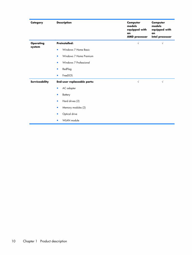
Operatingsystem
Preinstalled:
● Windows 7 Home Basic
● Windows 7 Home Premium
● Windows 7 Professional
● RedFlag
● FreeDOS
√ √
Serviceability End-user replaceable parts:
● AC adapter
● Battery
● Hard drives (2)
● Memory modules (2)
● Optical drive
● WLAN module
√ √
10 Chapter 1 Product description

2 External component identification
11
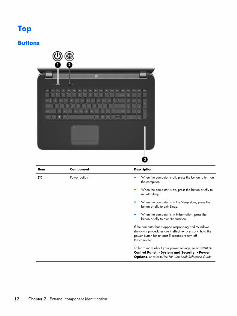
Top
Buttons
Item Component Description
(1) Power button ● When the computer is off, press the button to turn onthe computer.
● When the computer is on, press the button briefly toinitiate Sleep.
● When the computer is in the Sleep state, press thebutton briefly to exit Sleep.
● When the computer is in Hibernation, press thebutton briefly to exit Hibernation.
If the computer has stopped responding and Windowsshutdown procedures are ineffective, press and hold thepower button for at least 5 seconds to turn offthe computer.
To learn more about your power settings, select Start >Control Panel > System and Security > PowerOptions, or refer to the HP Notebook Reference Guide.
12 Chapter 2 External component identification
Item Component Description
(2) Web browser Opens a Web browser.
NOTE: Until you set up your Internet or networkservices, this button opens the InternetConnection Wizard.
(3) Fingerprint reader (select models only) Allows a fingerprint logon to Windows instead of apassword logon.
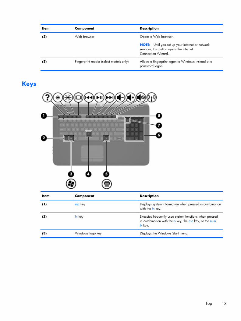
Keys
Item Component Description
(1) esc key Displays system information when pressed in combinationwith the fn key.
(2) fn key Executes frequently used system functions when pressedin combination with the b key, the esc key, or the numlk key.
(3) Windows logo key Displays the Windows Start menu.
Top 13
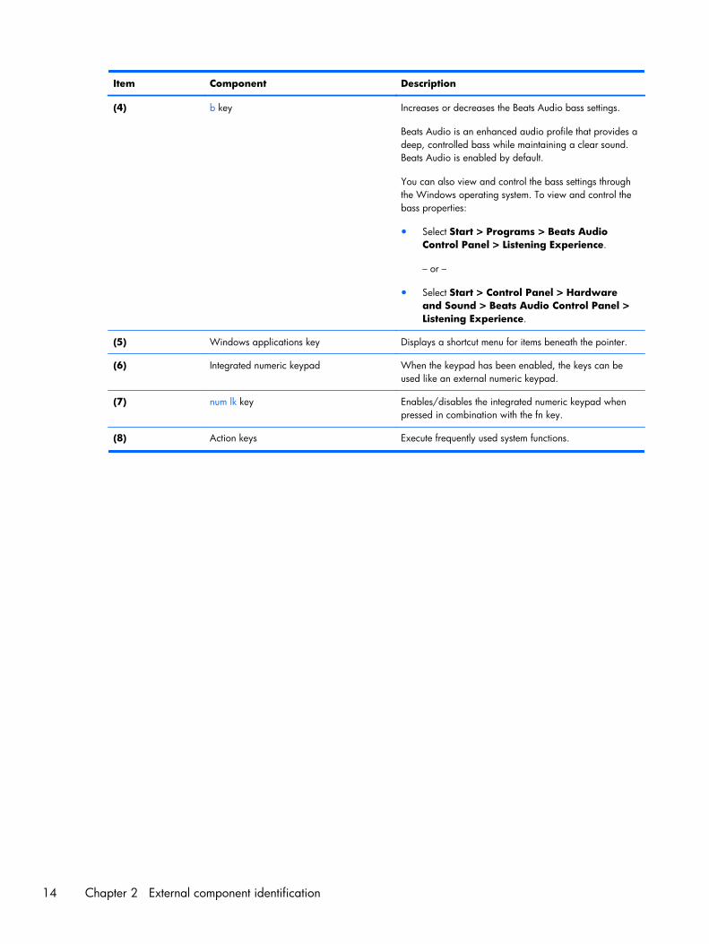
Item Component Description
(4) b key Increases or decreases the Beats Audio bass settings.
Beats Audio is an enhanced audio profile that provides adeep, controlled bass while maintaining a clear sound.Beats Audio is enabled by default.
You can also view and control the bass settings throughthe Windows operating system. To view and control thebass properties:
● Select Start > Programs > Beats AudioControl Panel > Listening Experience.
– or –
● Select Start > Control Panel > Hardwareand Sound > Beats Audio Control Panel >Listening Experience.
(5) Windows applications key Displays a shortcut menu for items beneath the pointer.
(6) Integrated numeric keypad When the keypad has been enabled, the keys can beused like an external numeric keypad.
(7) num lk key Enables/disables the integrated numeric keypad whenpressed in combination with the fn key.
(8) Action keys Execute frequently used system functions.
14 Chapter 2 External component identification
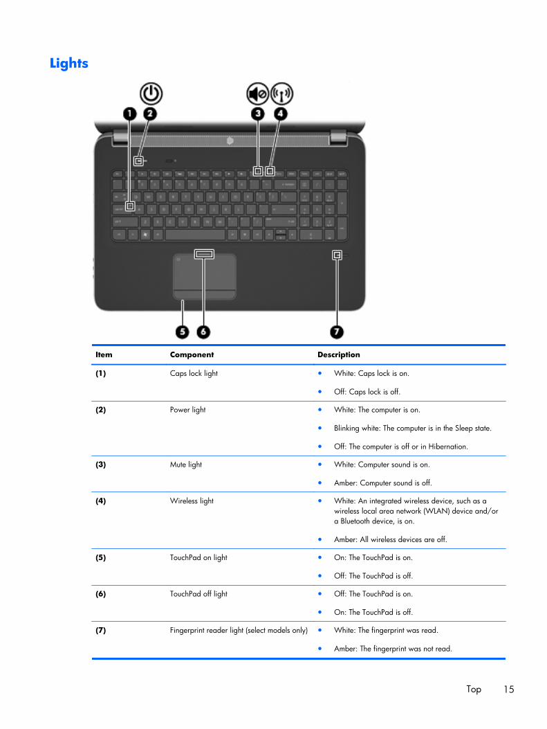
Lights
Item Component Description
(1) Caps lock light ● White: Caps lock is on.
● Off: Caps lock is off.
(2) Power light ● White: The computer is on.
● Blinking white: The computer is in the Sleep state.
● Off: The computer is off or in Hibernation.
(3) Mute light ● White: Computer sound is on.
● Amber: Computer sound is off.
(4) Wireless light ● White: An integrated wireless device, such as awireless local area network (WLAN) device and/ora Bluetooth device, is on.
● Amber: All wireless devices are off.
(5) TouchPad on light ● On: The TouchPad is on.
● Off: The TouchPad is off.
(6) TouchPad off light ● Off: The TouchPad is on.
● On: The TouchPad is off.
(7) Fingerprint reader light (select models only) ● White: The fingerprint was read.
● Amber: The fingerprint was not read.
Top 15
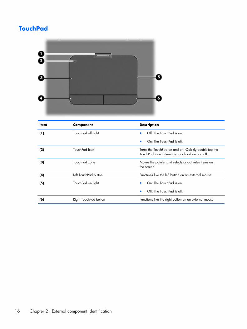
TouchPad
Item Component Description
(1) TouchPad off light ● Off: The TouchPad is on.
● On: The TouchPad is off.
(2) TouchPad icon Turns the TouchPad on and off. Quickly double-tap theTouchPad icon to turn the TouchPad on and off.
(3) TouchPad zone Moves the pointer and selects or activates items onthe screen.
(4) Left TouchPad button Functions like the left button on an external mouse.
(5) TouchPad on light ● On: The TouchPad is on.
● Off: The TouchPad is off.
(6) Right TouchPad button Functions like the right button on an external mouse.
16 Chapter 2 External component identification
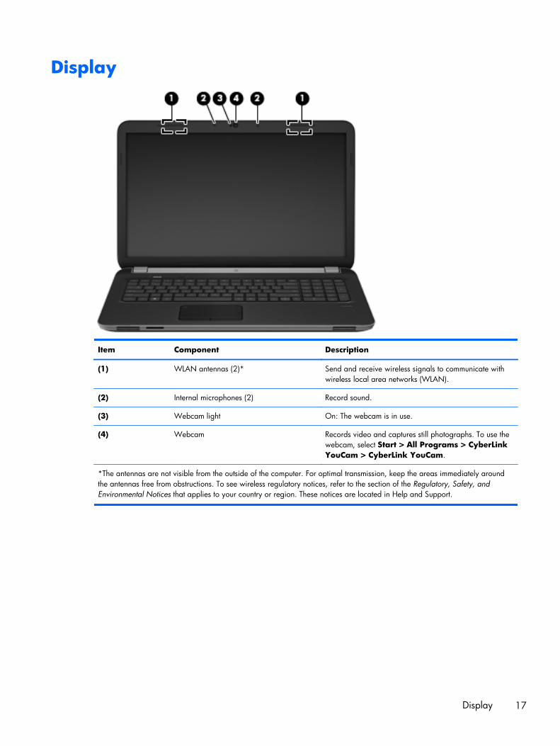
Display
Item Component Description
(1) WLAN antennas (2)* Send and receive wireless signals to communicate withwireless local area networks (WLAN).
(2) Internal microphones (2) Record sound.
(3) Webcam light On: The webcam is in use.
(4) Webcam Records video and captures still photographs. To use thewebcam, select Start > All Programs > CyberLinkYouCam > CyberLink YouCam.
*The antennas are not visible from the outside of the computer. For optimal transmission, keep the areas immediately aroundthe antennas free from obstructions. To see wireless regulatory notices, refer to the section of the Regulatory, Safety, andEnvironmental Notices that applies to your country or region. These notices are located in Help and Support.
Display 17
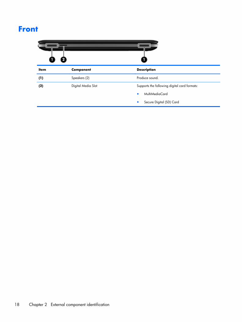
Front
Item Component Description
(1) Speakers (2) Produce sound.
(2) Digital Media Slot Supports the following digital card formats:
● MultiMediaCard
● Secure Digital (SD) Card
18 Chapter 2 External component identification
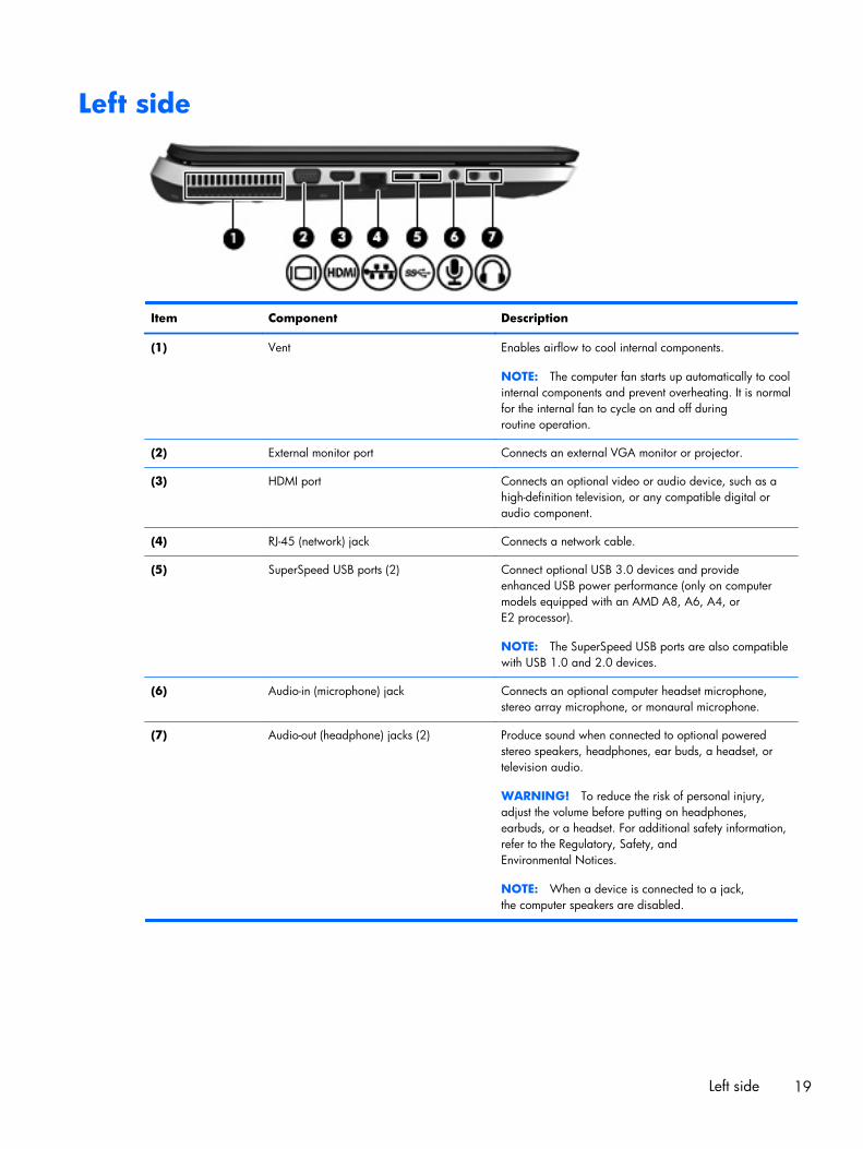
Left side
Item Component Description
(1) Vent Enables airflow to cool internal components.
NOTE: The computer fan starts up automatically to coolinternal components and prevent overheating. It is normalfor the internal fan to cycle on and off duringroutine operation.
(2) External monitor port Connects an external VGA monitor or projector.
(3) HDMI port Connects an optional video or audio device, such as ahigh-definition television, or any compatible digital oraudio component.
(4) RJ-45 (network) jack Connects a network cable.
(5) SuperSpeed USB ports (2) Connect optional USB 3.0 devices and provideenhanced USB power performance (only on computermodels equipped with an AMD A8, A6, A4, orE2 processor).
NOTE: The SuperSpeed USB ports are also compatiblewith USB 1.0 and 2.0 devices.
(6) Audio-in (microphone) jack Connects an optional computer headset microphone,stereo array microphone, or monaural microphone.
(7) Audio-out (headphone) jacks (2) Produce sound when connected to optional poweredstereo speakers, headphones, ear buds, a headset, ortelevision audio.
WARNING! To reduce the risk of personal injury,adjust the volume before putting on headphones,earbuds, or a headset. For additional safety information,refer to the Regulatory, Safety, andEnvironmental Notices.
NOTE: When a device is connected to a jack,the computer speakers are disabled.
Left side 19
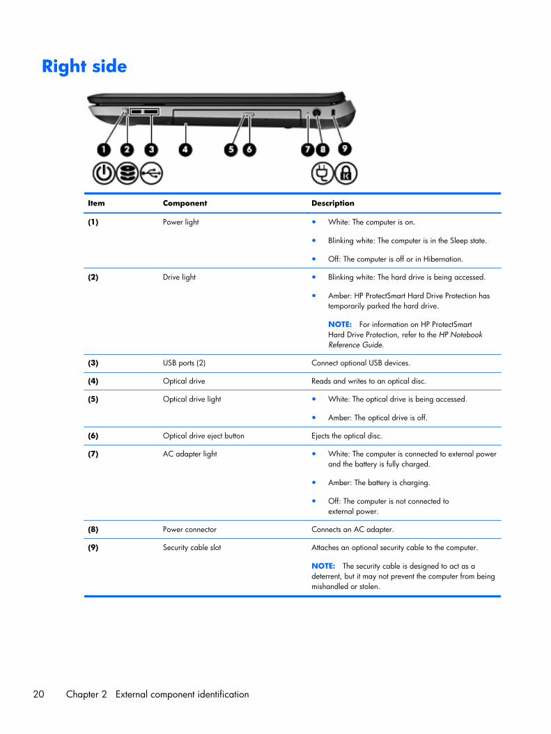
Right side
Item Component Description
(1) Power light ● White: The computer is on.
● Blinking white: The computer is in the Sleep state.
● Off: The computer is off or in Hibernation.
(2) Drive light ● Blinking white: The hard drive is being accessed.
● Amber: HP ProtectSmart Hard Drive Protection hastemporarily parked the hard drive.
NOTE: For information on HP ProtectSmartHard Drive Protection, refer to the HP NotebookReference Guide.
(3) USB ports (2) Connect optional USB devices.
(4) Optical drive Reads and writes to an optical disc.
(5) Optical drive light ● White: The optical drive is being accessed.
● Amber: The optical drive is off.
(6) Optical drive eject button Ejects the optical disc.
(7) AC adapter light ● White: The computer is connected to external powerand the battery is fully charged.
● Amber: The battery is charging.
● Off: The computer is not connected toexternal power.
(8) Power connector Connects an AC adapter.
(9) Security cable slot Attaches an optional security cable to the computer.
NOTE: The security cable is designed to act as adeterrent, but it may not prevent the computer from beingmishandled or stolen.
20 Chapter 2 External component identification

Bottom
Item Component Description
(1) Integrated subwoofer Provides superior bass sound.
(2) Vents (7) Enable airflow to cool internal components.
NOTE: The computer fan starts up automatically to coolinternal components and prevent overheating. It is normalfor the internal fan to cycle on and off duringroutine operation.
(3) Battery bay Holds the battery.
(4) Battery release latch Releases the battery from the battery bay, and releasesthe hard drive/memory module compartment cover.
(5) Hard drive bay Holds the hard drive and wireless LAN (WLAN) device,and contains the memory module slots.
CAUTION: To prevent an unresponsive system, replacethe wireless module only with a wireless moduleauthorized for use in the computer by the governmentalagency that regulates wireless devices in your country orregion. If you replace the module and then receive awarning message, remove the module to restorecomputer functionality, and then contact technical supportthrough Help and Support.
Bottom 21

3 Illustrated parts catalog
22 Chapter 3 Illustrated parts catalog
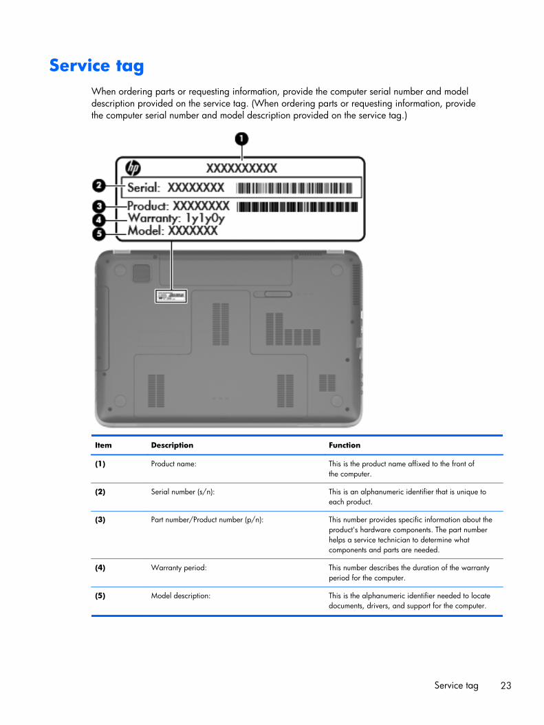
Service tagWhen ordering parts or requesting information, provide the computer serial number and modeldescription provided on the service tag. (When ordering parts or requesting information, providethe computer serial number and model description provided on the service tag.)
Item Description Function
(1) Product name: This is the product name affixed to the front ofthe computer.
(2) Serial number (s/n): This is an alphanumeric identifier that is unique toeach product.
(3) Part number/Product number (p/n): This number provides specific information about theproduct's hardware components. The part numberhelps a service technician to determine whatcomponents and parts are needed.
(4) Warranty period: This number describes the duration of the warrantyperiod for the computer.
(5) Model description: This is the alphanumeric identifier needed to locatedocuments, drivers, and support for the computer.
Service tag 23
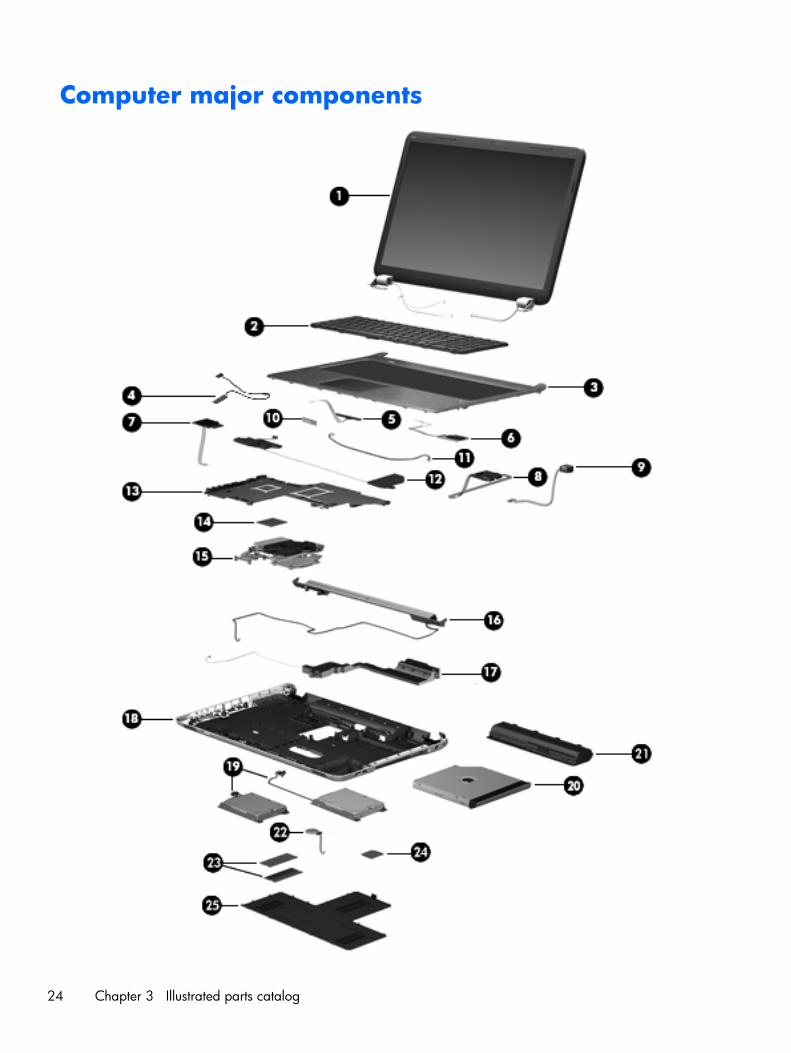
Computer major components
24 Chapter 3 Illustrated parts catalog
Item Component Spare part number
(1) Display assembly:
17.3-in, AntiGlare, full high-definition (FHD), light-emitting diode (LED) display assemblyin aluminum finish (includes webcam, two microphones, and wireless antenna transceiversand cables)
656295-001
17.3-in, AntiGlare, FHD, LED display assembly in steel gray finish (includes webcam, twomicrophones, and wireless antenna transceivers and cables)
656296-001
17.3-in, BrightView, high definition+ (HD+), LED, low-voltage differential signaling (LVDS)display assembly in steel gray finish (includes webcam, two microphones, and wirelessantenna transceivers and cables)
654442-001
17.3-in, BrightView, HD+, LED, LVDS display assembly in regular finish (includeswebcam, two microphones, and wireless antenna transceivers and cables)
639397-001
NOTE: For more display assembly spare part information, see Display assembly subcomponents on page 33.
(2) Keyboard (includes keyboard cable):
For use with all computer models:
For use in Belgium 639396-A41
For use in Canada 639396-121
For use in the Czech Republic 639396-221
For use in Denmark, Finland, and Norway 639396-DH1
For use in France 639396-051
For use in Germany 639396-041
For use in Greece 639396-DJ1
For use in Hungary 639396-211
For use in Italy 639396-061
For use in the Netherlands 639396-B31
For use in Portugal 639396-131
For use in Russia 639396-251
For use in Slovenia 639396-BA1
For use in Spain 639396-071
For use in Switzerland 639396-BG1
For use in the United Kingdom and Singapore 639396-031
For use in the United States 639396-001
For use only with computer models equipped with an Intel processor:
For use in Bulgaria 639396-261
For use in India 639396-D61
For use in Israel 639396-BB1
Computer major components 25
Item Component Spare part number
For use in Japan 639396-291
For use in Saudi Arabia 639396-171
For use in South Korea 639396-AD1
For use in Taiwan 639396-AB1
For use in Thailand 639396-281
For use in Turkey 639396-141
(3) Top cover (includes TouchPad and TouchPad cable and TouchPad button board and TouchPad buttonboard cable)
In steel gray finish 649947-001
In regular finish 639388-001
(4) Display lid switch board (includes cable) 647270-001
(5) Power button board (does not include cable) 640898-001
(6) Fingerprint reader board (includes bracket, but does not include cable) 640427-001
(7) SD Card reader board (does not include cable) 640899-001
(8) USB board (does not include cable) 646434-001
Cable Kit, includes: 639402-001
(9) Power connector cable
Not illustrated:
Fingerprint reader board cable
Power button board cable
SD Card reader board cable
TouchPad cable
TouchPad button board cables
USB board cable
(10) Bluetooth module (for use only with computer models equipped with an Intel processor, does not include cable):
EDR v.4.0 655792-001
EDR v.3.0 537921-001
(11) Bluetooth module cable (for use only with computer models equipped with anIntel processor)
647271-001
(12) Front speakers (includes front left and right speakers and cables) 639394-001
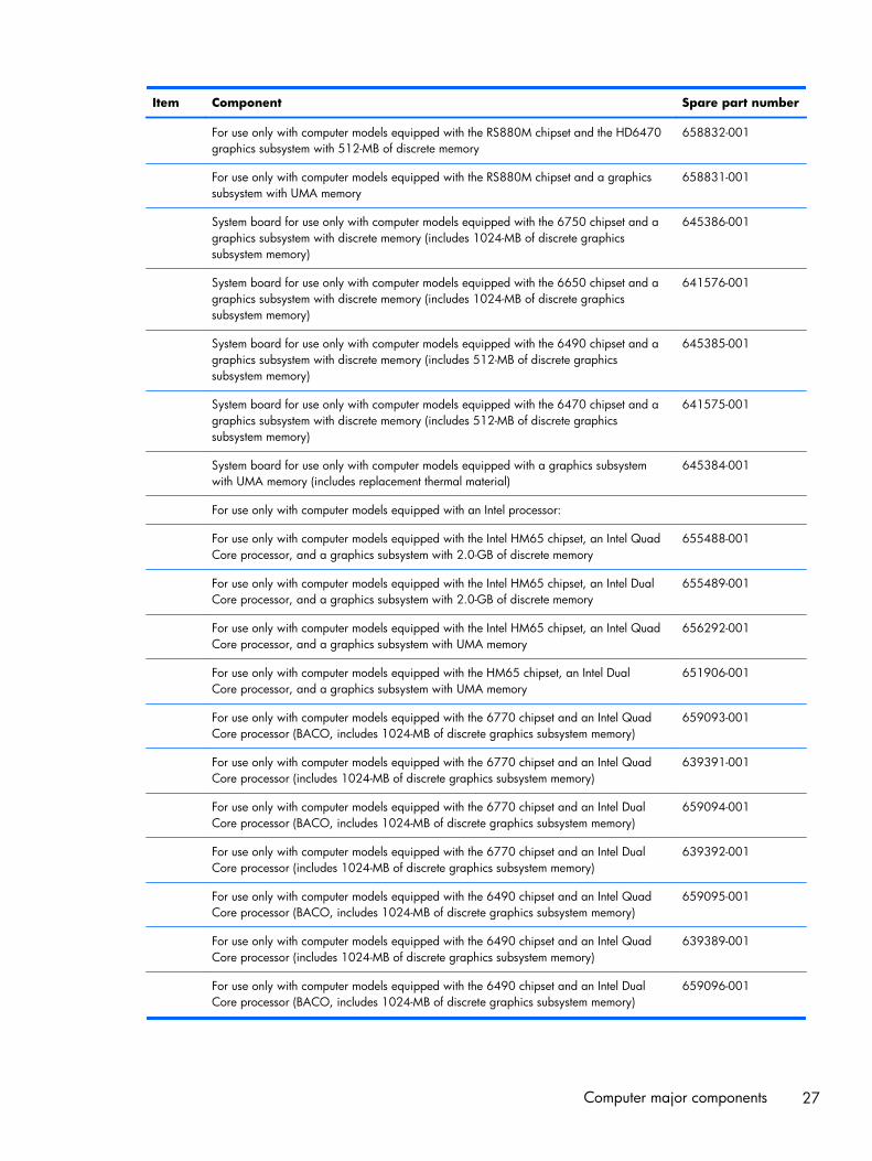
(13) System board (includes replacement thermal material):
For use only with computer models equipped with an AMD processor:
For use only with computer models equipped with the RS880M chipset and the HD6650graphics subsystem with 1.0-GB of discrete memory
658833-001
26 Chapter 3 Illustrated parts catalog
Item Component Spare part number
For use only with computer models equipped with the RS880M chipset and the HD6470graphics subsystem with 512-MB of discrete memory
658832-001
For use only with computer models equipped with the RS880M chipset and a graphicssubsystem with UMA memory
658831-001
System board for use only with computer models equipped with the 6750 chipset and agraphics subsystem with discrete memory (includes 1024-MB of discrete graphicssubsystem memory)
645386-001
System board for use only with computer models equipped with the 6650 chipset and agraphics subsystem with discrete memory (includes 1024-MB of discrete graphicssubsystem memory)
641576-001
System board for use only with computer models equipped with the 6490 chipset and agraphics subsystem with discrete memory (includes 512-MB of discrete graphicssubsystem memory)
645385-001
System board for use only with computer models equipped with the 6470 chipset and agraphics subsystem with discrete memory (includes 512-MB of discrete graphicssubsystem memory)
641575-001
System board for use only with computer models equipped with a graphics subsystemwith UMA memory (includes replacement thermal material)
645384-001
For use only with computer models equipped with an Intel processor:
For use only with computer models equipped with the Intel HM65 chipset, an Intel QuadCore processor, and a graphics subsystem with 2.0-GB of discrete memory
655488-001
For use only with computer models equipped with the Intel HM65 chipset, an Intel DualCore processor, and a graphics subsystem with 2.0-GB of discrete memory
655489-001
For use only with computer models equipped with the Intel HM65 chipset, an Intel QuadCore processor, and a graphics subsystem with UMA memory
656292-001
For use only with computer models equipped with the HM65 chipset, an Intel DualCore processor, and a graphics subsystem with UMA memory
651906-001
For use only with computer models equipped with the 6770 chipset and an Intel QuadCore processor (BACO, includes 1024-MB of discrete graphics subsystem memory)
659093-001
For use only with computer models equipped with the 6770 chipset and an Intel QuadCore processor (includes 1024-MB of discrete graphics subsystem memory)
639391-001
For use only with computer models equipped with the 6770 chipset and an Intel DualCore processor (BACO, includes 1024-MB of discrete graphics subsystem memory)
659094-001
For use only with computer models equipped with the 6770 chipset and an Intel DualCore processor (includes 1024-MB of discrete graphics subsystem memory)
639392-001
For use only with computer models equipped with the 6490 chipset and an Intel QuadCore processor (BACO, includes 1024-MB of discrete graphics subsystem memory)
659095-001
For use only with computer models equipped with the 6490 chipset and an Intel QuadCore processor (includes 1024-MB of discrete graphics subsystem memory)
639389-001
For use only with computer models equipped with the 6490 chipset and an Intel DualCore processor (BACO, includes 1024-MB of discrete graphics subsystem memory)
659096-001
Computer major components 27

Item Component Spare part number
For use only with computer models equipped with the 6490 chipset and an Intel DualCore processor (includes 1024-MB of discrete graphics subsystem memory)
639390-001
Thermal Material Kit (includes replacement thermal pads and paste):
For use only with computer models equipped with an AMD A8, A6, A4, or E2 processorand a graphics subsystem with discrete memory
654111-001
For use only with computer models equipped with an AMD A8, A6, A4, or E2 processorand a graphics subsystem with UMA memory
654112-001
For use only with computer models equipped with an AMD Athlon, Phenom, orTurion processor and a graphics subsystem with discrete memory
640457-001
For use only with computer models equipped with an AMD Athlon, Phenom, orTurion processor and a graphics subsystem with UMA memory
640456-001
For use only with computer models equipped with an Intel processor and a graphicssubsystem with 2-GB of discrete memory
650801-001
For use only with computer models equipped with an Intel processor and a graphicssubsystem with discrete memory
641493-001
For use only with computer models equipped with an Intel processor and a graphicssubsystem with UMA memory
641492-001
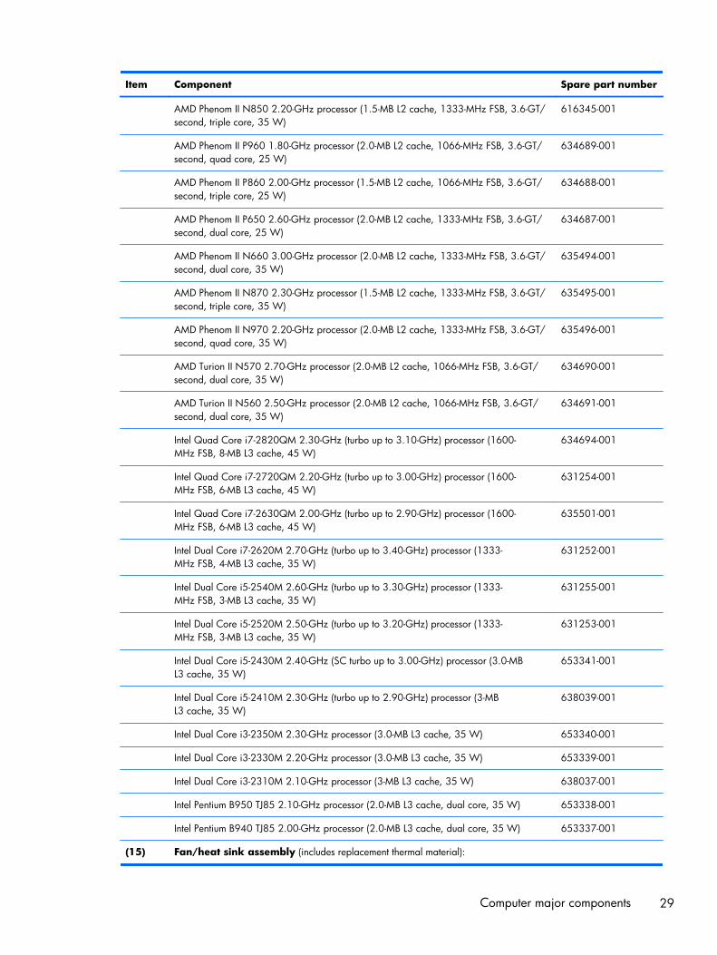
(14) Processor (includes replacement thermal material)
AMD A8-3530MX 2.60-GHz processor, (1.90-GHz FSB, 4.0-MB L2 cache,quad core, 45 W)
653364-001
AMD A8-3510MX 2.50-GHz processor (1.80-GHz FSB, 4.0-MB L2 cache,quad core, 45 W)
653358-001
AMD A8-3500M 2.40-GHz processor (1.50-GHz FSB, 4.0-MB L2 cache,quad core, 35 W)
653350-001
AMD A6-3410MX 2.30-GHz processor (1.60-GHz FSB, 2.0-MB L2 cache,quad core, 45 W)
653357-001
AMD A6-3400M 2.30-GHz processor (1.40-GHz FSB, 4.0-MB L2 cache,quad core, 35 W)
653349-001
AMD A4-3310MX 2.50-GHz processor (2.10-GHz FSB, 2.0-MB L2 cache,dual core, 45 W)
653356-001
AMD A4-3300M 2.50-GHz processor (1.90-GHz FSB, 2.0-MB L2 cache,dual core, 35 W)
653348-001
AMD E2-3000M 2.40-GHz processor (1.80-GHz FSB, 4.0-MB L2 cache,quad core, 35 W)
653351-001
AMD Athlon II N370 2.50-GHz processor (1.0-MB L2 cache, 1066-MHz FSB, 3.2-GT/second, dual core, 35 W)
634686-001
AMD Athlon II P340 2.20-GHz processor (1.0-MB L2 cache, 1066-MHz FSB, 3.2-GT/second, dual core, 25 W)
616343-001
AMD Athlon II P360 2.30-GHz processor (2.0-MB L2 cache, 1066-MHz FSB, 3.6-GT/second, dual core, 25 W)
636635-001
28 Chapter 3 Illustrated parts catalog
Item Component Spare part number
AMD Phenom II N850 2.20-GHz processor (1.5-MB L2 cache, 1333-MHz FSB, 3.6-GT/second, triple core, 35 W)
616345-001
AMD Phenom II P960 1.80-GHz processor (2.0-MB L2 cache, 1066-MHz FSB, 3.6-GT/second, quad core, 25 W)
634689-001
AMD Phenom II P860 2.00-GHz processor (1.5-MB L2 cache, 1066-MHz FSB, 3.6-GT/second, triple core, 25 W)
634688-001
AMD Phenom II P650 2.60-GHz processor (2.0-MB L2 cache, 1333-MHz FSB, 3.6-GT/second, dual core, 25 W)
634687-001
AMD Phenom II N660 3.00-GHz processor (2.0-MB L2 cache, 1333-MHz FSB, 3.6-GT/second, dual core, 35 W)
635494-001
AMD Phenom II N870 2.30-GHz processor (1.5-MB L2 cache, 1333-MHz FSB, 3.6-GT/second, triple core, 35 W)
635495-001
AMD Phenom II N970 2.20-GHz processor (2.0-MB L2 cache, 1333-MHz FSB, 3.6-GT/second, quad core, 35 W)
635496-001
AMD Turion II N570 2.70-GHz processor (2.0-MB L2 cache, 1066-MHz FSB, 3.6-GT/second, dual core, 35 W)
634690-001
AMD Turion II N560 2.50-GHz processor (2.0-MB L2 cache, 1066-MHz FSB, 3.6-GT/second, dual core, 35 W)
634691-001
Intel Quad Core i7-2820QM 2.30-GHz (turbo up to 3.10-GHz) processor (1600-MHz FSB, 8-MB L3 cache, 45 W)
634694-001
Intel Quad Core i7-2720QM 2.20-GHz (turbo up to 3.00-GHz) processor (1600-MHz FSB, 6-MB L3 cache, 45 W)
631254-001
Intel Quad Core i7-2630QM 2.00-GHz (turbo up to 2.90-GHz) processor (1600-MHz FSB, 6-MB L3 cache, 45 W)
635501-001
Intel Dual Core i7-2620M 2.70-GHz (turbo up to 3.40-GHz) processor (1333-MHz FSB, 4-MB L3 cache, 35 W)
631252-001
Intel Dual Core i5-2540M 2.60-GHz (turbo up to 3.30-GHz) processor (1333-MHz FSB, 3-MB L3 cache, 35 W)
631255-001
Intel Dual Core i5-2520M 2.50-GHz (turbo up to 3.20-GHz) processor (1333-MHz FSB, 3-MB L3 cache, 35 W)
631253-001
Intel Dual Core i5-2430M 2.40-GHz (SC turbo up to 3.00-GHz) processor (3.0-MBL3 cache, 35 W)
653341-001
Intel Dual Core i5-2410M 2.30-GHz (turbo up to 2.90-GHz) processor (3-MBL3 cache, 35 W)
638039-001
Intel Dual Core i3-2350M 2.30-GHz processor (3.0-MB L3 cache, 35 W) 653340-001
Intel Dual Core i3-2330M 2.20-GHz processor (3.0-MB L3 cache, 35 W) 653339-001
Intel Dual Core i3-2310M 2.10-GHz processor (3-MB L3 cache, 35 W) 638037-001
Intel Pentium B950 TJ85 2.10-GHz processor (2.0-MB L3 cache, dual core, 35 W) 653338-001
Intel Pentium B940 TJ85 2.00-GHz processor (2.0-MB L3 cache, dual core, 35 W) 653337-001
(15) Fan/heat sink assembly (includes replacement thermal material):
Computer major components 29

Item Component Spare part number
For use only with computer models equipped with the AMD A70M chipset and a graphicssubsystem with discrete memory
650057-001
For use only with computer models equipped with the AMD A70M chipset and a graphicssubsystem with UMA memory
650056-001
For use only with computer models equipped with an AMD processor and a graphicssubsystem with discrete memory
641578-001
For use only with computer models equipped with an AMD processor and a graphicssubsystem with UMA memory
639404-001
For use only with computer models equipped with an Intel processor and a graphicssubsystem with 2.0-GB of discrete memory
653627-001
For use only with computer models equipped with an Intel processor and a graphicssubsystem with UMA memory
653628-001
For use only with computer models equipped with an Intel processor 640903-001
(16) Rear speakers (includes rear left and right speakers, grill, and cable) 641304-001
(17) Subwoofer (includes isolators and cable) 639393-001
(18) Base enclosure (includes battery release latch and 4 rubber feet):
For use only with computer models equipped with an Intel processor (includes openingsfor 3 USB ports)
639399-001
For use only with computer models equipped with an AMD processor (includes openingsfor 2 USB ports)
657988-001
(19) Hard drive (2, 2.5-in, SATA, does not include bracket, connector cable, shield, or screws):
1-TB, 5400-rpm 638974-001
750-GB, 7200-rpm 633252-001
750-GB, 5400-rpm 634250-001
640-GB, 7200-rpm 621046-001
500-GB, 7200-rpm for use only with computer models equipped with an Intel processor 608218-001
320-GB, 7200-rpm 634862-001 and641672-001
250-GB, 7200-rpm 634861-001 and635225-001
Hard Drive Hardware Kit (not illustrated, includes bracket, connector cable, shield,and screws)
641306-001
160-GB solid-state drive for use only with computer models equipped with anIntel processor (not illustrated, does not include bracket, connector cable, shield,or screws)
639405-001
(20) Optical drive (includes bezel and bracket):
For use with all computer models:
Blu-ray Disc R/RW with SuperMulti DVD±R/RW Double-Layer Drive with LightScribe 659876-001
30 Chapter 3 Illustrated parts catalog
Item Component Spare part number
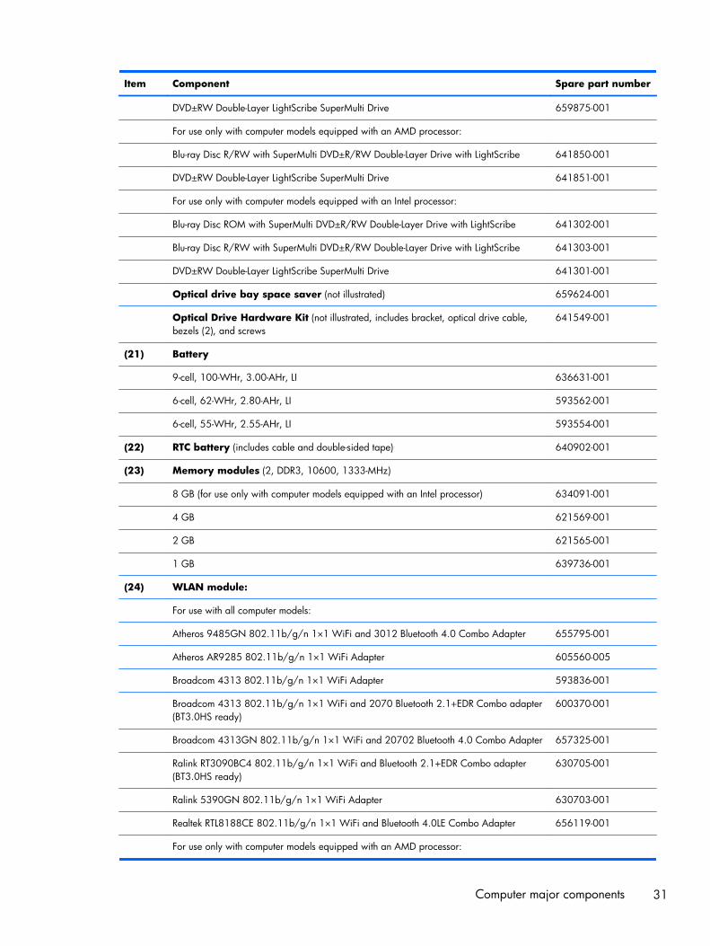
DVD±RW Double-Layer LightScribe SuperMulti Drive 659875-001
For use only with computer models equipped with an AMD processor:
Blu-ray Disc R/RW with SuperMulti DVD±R/RW Double-Layer Drive with LightScribe 641850-001
DVD±RW Double-Layer LightScribe SuperMulti Drive 641851-001
For use only with computer models equipped with an Intel processor:
Blu-ray Disc ROM with SuperMulti DVD±R/RW Double-Layer Drive with LightScribe 641302-001
Blu-ray Disc R/RW with SuperMulti DVD±R/RW Double-Layer Drive with LightScribe 641303-001
DVD±RW Double-Layer LightScribe SuperMulti Drive 641301-001
Optical drive bay space saver (not illustrated) 659624-001
Optical Drive Hardware Kit (not illustrated, includes bracket, optical drive cable,bezels (2), and screws
641549-001
(21) Battery
9-cell, 100-WHr, 3.00-AHr, LI 636631-001
6-cell, 62-WHr, 2.80-AHr, LI 593562-001
6-cell, 55-WHr, 2.55-AHr, LI 593554-001
(22) RTC battery (includes cable and double-sided tape) 640902-001
(23) Memory modules (2, DDR3, 10600, 1333-MHz)
8 GB (for use only with computer models equipped with an Intel processor) 634091-001
4 GB 621569-001
2 GB 621565-001
1 GB 639736-001
(24) WLAN module:
For use with all computer models:
Atheros 9485GN 802.11b/g/n 1×1 WiFi and 3012 Bluetooth 4.0 Combo Adapter 655795-001
Atheros AR9285 802.11b/g/n 1×1 WiFi Adapter 605560-005
Broadcom 4313 802.11b/g/n 1×1 WiFi Adapter 593836-001
Broadcom 4313 802.11b/g/n 1×1 WiFi and 2070 Bluetooth 2.1+EDR Combo adapter(BT3.0HS ready)
600370-001
Broadcom 4313GN 802.11b/g/n 1×1 WiFi and 20702 Bluetooth 4.0 Combo Adapter 657325-001
Ralink RT3090BC4 802.11b/g/n 1×1 WiFi and Bluetooth 2.1+EDR Combo adapter(BT3.0HS ready)
630705-001
Ralink 5390GN 802.11b/g/n 1×1 WiFi Adapter 630703-001
Realtek RTL8188CE 802.11b/g/n 1×1 WiFi and Bluetooth 4.0LE Combo Adapter 656119-001
For use only with computer models equipped with an AMD processor:
Computer major components 31

Item Component Spare part number
Atheros AR9002WB-1NGB 802.11b/g/n 1×1 WiFi and Bluetooth 2.1EDR+ ComboAdapter (BT3.0+HS ready)
593127-001
Realtek 8188BC8 802.11a/b/g/n 2×2 WiFi and Bluetooth 3.0+HS Combo Adapter 602993-001
Realtek 8188GN 802.11b/g/n 1×1 WiFi Adapter 640926-001
For use only with computer models equipped with an Intel processor:
Intel Centrino Advanced-N 6230 631956-001
Intel Centrino Wireless-N 1000 802.11b/g/n 1×2 WLAN module 593530-001
Intel Centrino Wireless-N + WiMAX 6150 633817-001
(25) Service cover — available in the Plastics Kit, spare part number 641305-001)
32 Chapter 3 Illustrated parts catalog
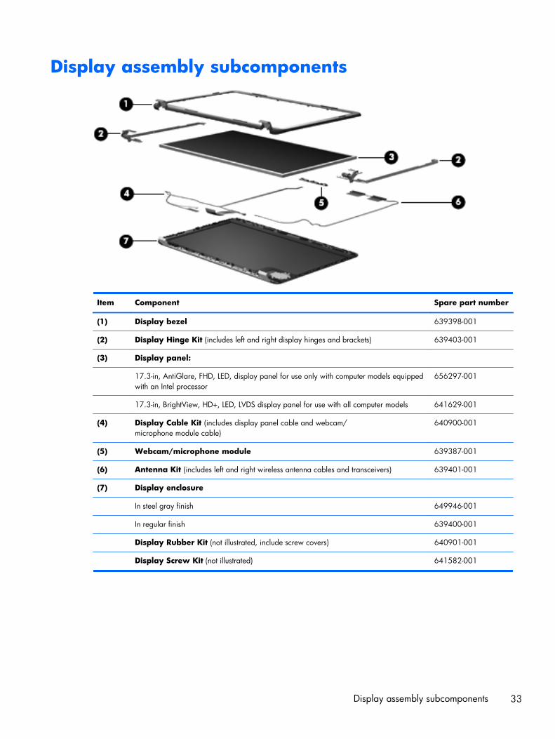
Display assembly subcomponents
Item Component Spare part number
(1) Display bezel 639398-001
(2) Display Hinge Kit (includes left and right display hinges and brackets) 639403-001
(3) Display panel:
17.3-in, AntiGlare, FHD, LED, display panel for use only with computer models equippedwith an Intel processor
656297-001
17.3-in, BrightView, HD+, LED, LVDS display panel for use with all computer models 641629-001
(4) Display Cable Kit (includes display panel cable and webcam/microphone module cable)
640900-001
(5) Webcam/microphone module 639387-001
(6) Antenna Kit (includes left and right wireless antenna cables and transceivers) 639401-001
(7) Display enclosure
In steel gray finish 649946-001
In regular finish 639400-001
Display Rubber Kit (not illustrated, include screw covers) 640901-001
Display Screw Kit (not illustrated) 641582-001
Display assembly subcomponents 33
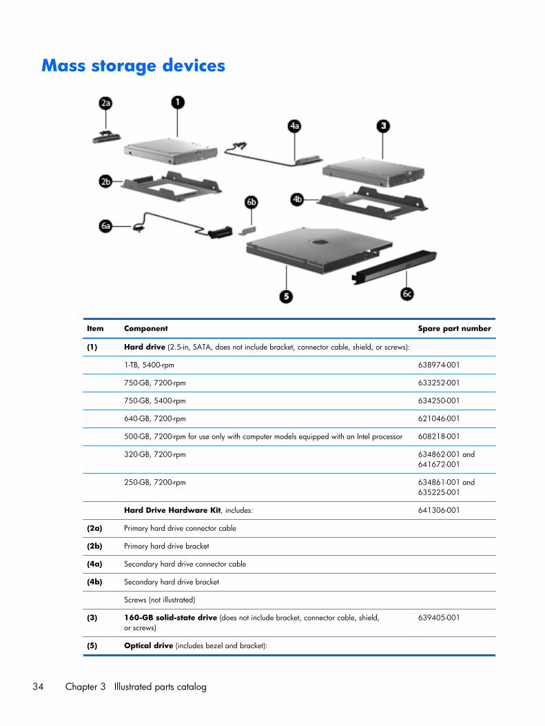
Mass storage devices
Item Component Spare part number
(1) Hard drive (2.5-in, SATA, does not include bracket, connector cable, shield, or screws):
1-TB, 5400-rpm 638974-001
750-GB, 7200-rpm 633252-001
750-GB, 5400-rpm 634250-001
640-GB, 7200-rpm 621046-001
500-GB, 7200-rpm for use only with computer models equipped with an Intel processor 608218-001
320-GB, 7200-rpm 634862-001 and641672-001
250-GB, 7200-rpm 634861-001 and635225-001
Hard Drive Hardware Kit, includes: 641306-001
(2a) Primary hard drive connector cable
(2b) Primary hard drive bracket
(4a) Secondary hard drive connector cable
(4b) Secondary hard drive bracket
Screws (not illustrated)
(3) 160-GB solid-state drive (does not include bracket, connector cable, shield,or screws)
639405-001
(5) Optical drive (includes bezel and bracket):
34 Chapter 3 Illustrated parts catalog
Item Component Spare part number
For use with all computer models:
Blu-ray Disc R/RW with SuperMulti DVD±R/RW Double-Layer Drive with LightScribe 659876-001
DVD±RW Double-Layer LightScribe SuperMulti Drive 659875-001
For use only with computer models equipped with an AMD processor:
Blu-ray Disc R/RW with SuperMulti DVD±R/RW Double-Layer Drive with LightScribe 641850-001
DVD±RW Double-Layer LightScribe SuperMulti Drive 641851-001
For use only with computer models equipped with an Intel processor:
Blu-ray Disc ROM with SuperMulti DVD±R/RW Double-Layer Drive with LightScribe 641302-001
Blu-ray Disc R/RW with SuperMulti DVD±R/RW Double-Layer Drive with LightScribe 641303-001
DVD±RW Double-Layer LightScribe SuperMulti Drive 641301-001
Optical drive bay space saver (not illustrated) 659624-001
Optical Drive Hardware Kit, includes: 641549-001
(6a) Optical drive cable
(6b) Optical drive bracket
(6c) Optical drive bezel
Screws (not illustrated)
Miscellaneous parts
Component Spare part number
HP Smart AC adapter
90-W, PFC, RC, V HP Smart AC adapter for use with all computer models 609940-001
65-W RC, V HP Smart AC adapter for use only with computer models equipped with anAMD processor
609939-001
120-W, PFC, RC, V HP Smart AC adapter for use only with computer models equipped with anIntel processor
609941-001
90-W, PFC, RC, V, EM HP Smart AC adapter for use only with computer models equipped with anIntel processor
609947-001
65-W, RC, V, EM HP Smart AC adapter for use only with computer models equipped with anIntel processor
609948-001
Power cord (3-pin, black,1.83-meter):
For use with all computer models:
For use in Denmark 490371-081
For use in Europe 490371-021
Miscellaneous parts 35
Component Spare part number
For use in Italy 490371-061
For use in North America 490371-001
For use in the Netherlands 490371-B31
For use in Switzerland 490371-111
For use in the United Kingdom and Singapore 490371-031
For use only with computer models equipped with an Intel processor:
For use in Australia 490371-011
For use in Brazil 490371-201
For use in India 490371-D61
For use in Israel 490371-BB1
For use in Japan 490371-291
For use in South Korea 490371-AD1
For use in Taiwan 490371-AB1
Remote control (full-function with teletext) 465541-004
Screw Kit 639395-001
USB DVB-T dipole antenna 581223-001
USB DVB-T TV tuner 581222-001
Sequential part number listing
Spare partnumber
Description
465541-004 Remote control (full-function with teletext)
490371-001 Power cord for use with all computer models in North America (3-pin, black,1.83-meter)
490371-011 Power cord for use only with computer models equipped with an Intel processor in Australia (3-pin,black,1.83-meter)
490371-021 Power cord for use with all computer models in Europe (3-pin, black,1.83-meter)
490371-031 Power cord for use with all computer models in the United Kingdom and Singapore (3-pin, black,1.83-meter)
490371-061 Power cord for use with all computer models in Italy (3-pin, black,1.83-meter)
490371-081 Power cord for use with all computer models in Denmark (3-pin, black,1.83-meter)
490371-111 Power cord for use with all computer models in Switzerland (3-pin, black,1.83-meter)
490371-201 Power cord for use only with computer models equipped with an Intel processor in Brazil (3-pin, black,1.83-meter)
36 Chapter 3 Illustrated parts catalog
Spare partnumber
Description
490371-291 Power cord for use only with computer models equipped with an Intel processor in Japan (3-pin, black,1.83-meter)
490371-AB1 Power cord for use only with computer models equipped with an Intel processor in Taiwan (3-pin,black,1.83-meter)
490371-AD1 Power cord for use only with computer models equipped with an Intel processor in South Korea (3-pin,black,1.83-meter)
490371-AR1 Power cord for use with all computer models in South Africa (3-pin, black,1.83-meter)
490371-BB1 Power cord for use only with computer models equipped with an Intel processor in Israel (3-pin, black,1.83-meter)
490371-D61 Power cord for use only with computer models equipped with an Intel processor in India (3-pin, black,1.83-meter)
537921-001 Bluetooth module EDR v.3.0 (for use only with computer models equipped with an Intel processor, doesnot include cable)
581222-001 USB DVB-T TV tuner
581223-001 USB DVB-T dipole antenna
593127-001 Atheros AR9002WB-1NGB 802.11b/g/n 1×1 WiFi and Bluetooth 2.1EDR+ Combo Adapter(BT3.0+HS ready) for use only with computer models equipped with an AMD processor
593530-001 Intel Centrino Wireless-N 1000 802.11b/g/n 1×2 WLAN module for use only with computer modelsequipped with an Intel processor
593554-001 6-cell, 55-WHr, 2.55-AHr, Li battery
593562-001 6-cell, 62-WHr, 2.80-AHr, Li battery
593836-001 Broadcom 4313 802.11b/g/n 1×1 WiFi Adapter for use with all computer models
600370-001 Broadcom 4313 802.11b/g/n 1×1 WiFi and 2070 Bluetooth 2.1+EDR Combo adapter(BT3.0HS ready) for use with all computer models
602993-001 Realtek 8188BC8 802.11a/b/g/n 2×2 WiFi and Bluetooth 3.0+HS Combo Adapter for use only withcomputer models equipped with an AMD processor
605560-005 Atheros AR9285 802.11b/g/n 1×1 WiFi Adapter for use only with computer models equipped withan AMD processor
608218-001 500-GB, 7200-rpm hard drive for use only with computer models equipped with an Intel processor(2.5-in, SATA, does not include bracket, connector cable, shield, or screws)
609939-001 65-W RC, V HP Smart AC adapter for use only with computer models equipped with anAMD processor
609940-001 90-W, PFC, RC, V HP Smart AC adapter
609941-001 120-W, PFC, RC, V HP Smart AC adapter for use only with computer models equipped with anIntel processor
609947-001 90-W, PFC, RC, V, EM HP Smart AC adapter for use only with computer models equipped with anIntel processor
609948-001 65-W, RC, V, EM HP Smart AC adapter for use only with computer models equipped with anIntel processor
Sequential part number listing 37
Spare partnumber
Description
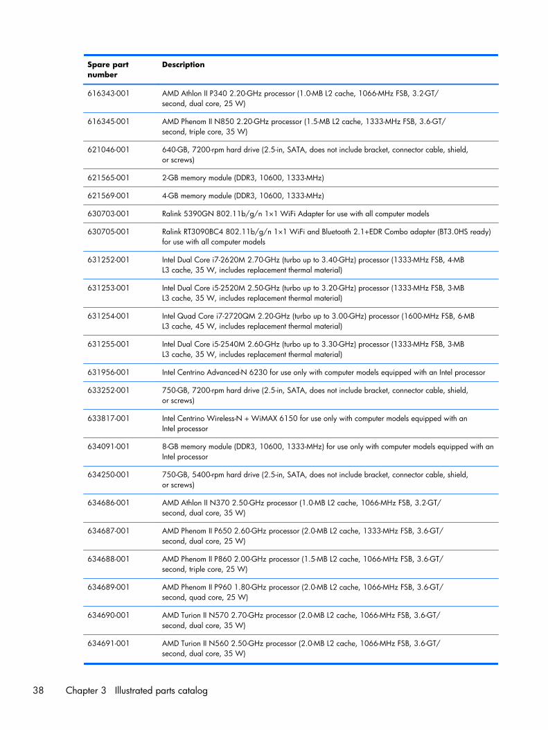
616343-001 AMD Athlon II P340 2.20-GHz processor (1.0-MB L2 cache, 1066-MHz FSB, 3.2-GT/second, dual core, 25 W)
616345-001 AMD Phenom II N850 2.20-GHz processor (1.5-MB L2 cache, 1333-MHz FSB, 3.6-GT/second, triple core, 35 W)
621046-001 640-GB, 7200-rpm hard drive (2.5-in, SATA, does not include bracket, connector cable, shield,or screws)
621565-001 2-GB memory module (DDR3, 10600, 1333-MHz)
621569-001 4-GB memory module (DDR3, 10600, 1333-MHz)
630703-001 Ralink 5390GN 802.11b/g/n 1×1 WiFi Adapter for use with all computer models
630705-001 Ralink RT3090BC4 802.11b/g/n 1×1 WiFi and Bluetooth 2.1+EDR Combo adapter (BT3.0HS ready)for use with all computer models
631252-001 Intel Dual Core i7-2620M 2.70-GHz (turbo up to 3.40-GHz) processor (1333-MHz FSB, 4-MBL3 cache, 35 W, includes replacement thermal material)
631253-001 Intel Dual Core i5-2520M 2.50-GHz (turbo up to 3.20-GHz) processor (1333-MHz FSB, 3-MBL3 cache, 35 W, includes replacement thermal material)
631254-001 Intel Quad Core i7-2720QM 2.20-GHz (turbo up to 3.00-GHz) processor (1600-MHz FSB, 6-MBL3 cache, 45 W, includes replacement thermal material)
631255-001 Intel Dual Core i5-2540M 2.60-GHz (turbo up to 3.30-GHz) processor (1333-MHz FSB, 3-MBL3 cache, 35 W, includes replacement thermal material)
631956-001 Intel Centrino Advanced-N 6230 for use only with computer models equipped with an Intel processor
633252-001 750-GB, 7200-rpm hard drive (2.5-in, SATA, does not include bracket, connector cable, shield,or screws)
633817-001 Intel Centrino Wireless-N + WiMAX 6150 for use only with computer models equipped with anIntel processor
634091-001 8-GB memory module (DDR3, 10600, 1333-MHz) for use only with computer models equipped with anIntel processor
634250-001 750-GB, 5400-rpm hard drive (2.5-in, SATA, does not include bracket, connector cable, shield,or screws)
634686-001 AMD Athlon II N370 2.50-GHz processor (1.0-MB L2 cache, 1066-MHz FSB, 3.2-GT/second, dual core, 35 W)
634687-001 AMD Phenom II P650 2.60-GHz processor (2.0-MB L2 cache, 1333-MHz FSB, 3.6-GT/second, dual core, 25 W)
634688-001 AMD Phenom II P860 2.00-GHz processor (1.5-MB L2 cache, 1066-MHz FSB, 3.6-GT/second, triple core, 25 W)
634689-001 AMD Phenom II P960 1.80-GHz processor (2.0-MB L2 cache, 1066-MHz FSB, 3.6-GT/second, quad core, 25 W)
634690-001 AMD Turion II N570 2.70-GHz processor (2.0-MB L2 cache, 1066-MHz FSB, 3.6-GT/second, dual core, 35 W)
634691-001 AMD Turion II N560 2.50-GHz processor (2.0-MB L2 cache, 1066-MHz FSB, 3.6-GT/second, dual core, 35 W)
38 Chapter 3 Illustrated parts catalog

Spare partnumber
Description
634694-001 Intel Quad Core i7-2820QM 2.30-GHz (turbo up to 3.10-GHz) processor (1600-MHz FSB, 8-MBL3 cache, 45 W, includes replacement thermal material)
634861-001 250-GB, 7200-rpm hard drive (2.5-in, SATA, does not include bracket, connector cable, shield,or screws)
634862-001 320-GB, 7200-rpm hard drive (2.5-in, SATA, does not include bracket, connector cable, shield,or screws)
635225-001 250-GB, 7200-rpm hard drive (2.5-in, SATA, does not include bracket, connector cable, shield,or screws)
635494-001 AMD Phenom II N660 3.00-GHz processor (2.0-MB L2 cache, 1333-MHz FSB, 3.6-GT/second, DualCore 35 W)
635495-001 AMD Phenom II N870 2.30-GHz processor (1.5-MB L2 cache, 1333-MHz FSB, 3.6-GT/second, triple core, 35 W)
635496-001 AMD Phenom II N970 2.20-GHz processor (2.0-MB L2 cache, 1333-MHz FSB, 3.6-GT/second, quad core, 35 W)
635501-001 Intel Quad Core i7-2630QM 2.00-GHz (turbo up to 2.90-GHz) processor (1600-MHz FSB, 6-MBL3 cache, 45 W, includes replacement thermal material)
636631-001 9-cell, 100-WHr, 3.00-AHr, Li battery
636635-001 AMD Athlon II P360 2.30-GHz processor (2.0-MB L2 cache, 1066-MHz FSB, 3.6-GT/second, dual core, 25 W)
638037-001 Intel Dual Core i3-2310M 2.10-GHz processor (3-MB L3 cache, 35 W, includes replacementthermal material)
638039-001 Intel Dual Core i5-2410M 2.30-GHz (turbo up to 2.90-GHz) processor (3-MB L3 cache, 35 W,includes replacement thermal material)
638974-001 1-TB, 5400-rpm hard drive (2.5-in, SATA, does not include bracket, connector cable, shield, or screws)
639387-001 Webcam/microphone module
639388-001 Top cover in regular finish (includes TouchPad and TouchPad cable and TouchPad button board andTouchPad button board cable)
639389-001 System board for use only with computer models equipped with an Intel Quad Core processor and the6490 chipset (includes 1024-MB of discrete graphics subsystem memory and replacementthermal material)
639390-001 System board for use only with computer models equipped with an Intel Dual Core processor and the6490 chipset (includes 1024-MB of discrete graphics subsystem memory and replacementthermal material)
639391-001 System board for use only with computer models equipped with an Intel Quad Core processor and the6770 chipset (includes 1024-MB of discrete graphics subsystem memory and replacementthermal material)
639392-001 System board for use only with computer models equipped with an Intel Dual Core processor and the6770 chipset (includes 1024-MB of discrete graphics subsystem memory and replacementthermal material)
639393-001 Subwoofer (includes isolators and cable)
Sequential part number listing 39
Spare partnumber
Description
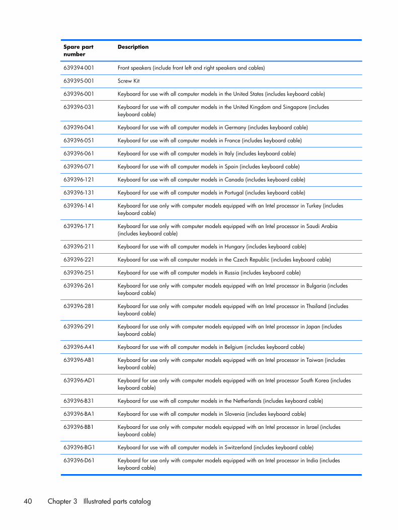
639394-001 Front speakers (include front left and right speakers and cables)
639395-001 Screw Kit
639396-001 Keyboard for use with all computer models in the United States (includes keyboard cable)
639396-031 Keyboard for use with all computer models in the United Kingdom and Singapore (includeskeyboard cable)
639396-041 Keyboard for use with all computer models in Germany (includes keyboard cable)
639396-051 Keyboard for use with all computer models in France (includes keyboard cable)
639396-061 Keyboard for use with all computer models in Italy (includes keyboard cable)
639396-071 Keyboard for use with all computer models in Spain (includes keyboard cable)
639396-121 Keyboard for use with all computer models in Canada (includes keyboard cable)
639396-131 Keyboard for use with all computer models in Portugal (includes keyboard cable)
639396-141 Keyboard for use only with computer models equipped with an Intel processor in Turkey (includeskeyboard cable)
639396-171 Keyboard for use only with computer models equipped with an Intel processor in Saudi Arabia(includes keyboard cable)
639396-211 Keyboard for use with all computer models in Hungary (includes keyboard cable)
639396-221 Keyboard for use with all computer models in the Czech Republic (includes keyboard cable)
639396-251 Keyboard for use with all computer models in Russia (includes keyboard cable)
639396-261 Keyboard for use only with computer models equipped with an Intel processor in Bulgaria (includeskeyboard cable)
639396-281 Keyboard for use only with computer models equipped with an Intel processor in Thailand (includeskeyboard cable)
639396-291 Keyboard for use only with computer models equipped with an Intel processor in Japan (includeskeyboard cable)
639396-A41 Keyboard for use with all computer models in Belgium (includes keyboard cable)
639396-AB1 Keyboard for use only with computer models equipped with an Intel processor in Taiwan (includeskeyboard cable)
639396-AD1 Keyboard for use only with computer models equipped with an Intel processor South Korea (includeskeyboard cable)
639396-B31 Keyboard for use with all computer models in the Netherlands (includes keyboard cable)
639396-BA1 Keyboard for use with all computer models in Slovenia (includes keyboard cable)
639396-BB1 Keyboard for use only with computer models equipped with an Intel processor in Israel (includeskeyboard cable)
639396-BG1 Keyboard for use with all computer models in Switzerland (includes keyboard cable)
639396-D61 Keyboard for use only with computer models equipped with an Intel processor in India (includeskeyboard cable)
40 Chapter 3 Illustrated parts catalog
Spare partnumber
Description
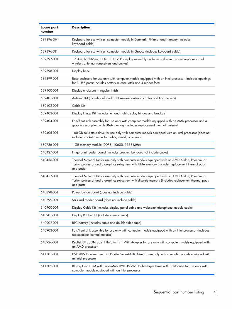
639396-DH1 Keyboard for use with all computer models in Denmark, Finland, and Norway (includeskeyboard cable)
639396-DJ1 Keyboard for use with all computer models in Greece (includes keyboard cable)
639397-001 17.3-in, BrightView, HD+, LED, LVDS display assembly (includes webcam, two microphones, andwireless antenna transceivers and cables)
639398-001 Display bezel
639399-001 Base enclosure for use only with computer models equipped with an Intel processor (includes openingsfor 3 USB ports; includes battery release latch and 4 rubber feet)
639400-001 Display enclosure in regular finish
639401-001 Antenna Kit (includes left and right wireless antenna cables and transceivers)
639402-001 Cable Kit
639403-001 Display Hinge Kit (includes left and right display hinges and brackets)
639404-001 Fan/heat sink assembly for use only with computer models equipped with an AMD processor and agraphics subsystem with UMA memory (includes replacement thermal material)
639405-001 160-GB solid-state drive for use only with computer models equipped with an Intel processor (does notinclude bracket, connector cable, shield, or screws)
639736-001 1-GB memory module (DDR3, 10600, 1333-MHz)
640427-001 Fingerprint reader board (includes bracket, but does not include cable)
640456-001 Thermal Material Kit for use only with computer models equipped with an AMD Athlon, Phenom, orTurion processor and a graphics subsystem with UMA memory (includes replacement thermal padsand paste)
640457-001 Thermal Material Kit for use only with computer models equipped with an AMD Athlon, Phenom, orTurion processor and a graphics subsystem with discrete memory (includes replacement thermal padsand paste)
640898-001 Power button board (does not include cable)
640899-001 SD Card reader board (does not include cable)
640900-001 Display Cable Kit (includes display panel cable and webcam/microphone module cable)
640901-001 Display Rubber Kit (include screw covers)
640902-001 RTC battery (includes cable and double-sided tape)
640903-001 Fan/heat sink assembly for use only with computer models equipped with an Intel processor (includesreplacement thermal material)
640926-001 Realtek 8188GN 802.11b/g/n 1×1 WiFi Adapter for use only with computer models equipped withan AMD processor
641301-001 DVD±RW Double-Layer LightScribe SuperMulti Drive for use only with computer models equipped withan Intel processor
641302-001 Blu-ray Disc ROM with SuperMulti DVD±R/RW Double-Layer Drive with LightScribe for use only withcomputer models equipped with an Intel processor
Sequential part number listing 41
Spare partnumber
Description
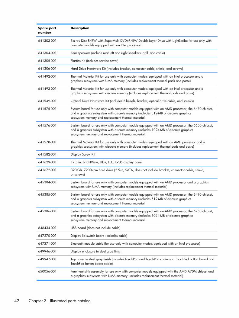
641303-001 Blu-ray Disc R/RW with SuperMulti DVD±R/RW Double-Layer Drive with LightScribe for use only withcomputer models equipped with an Intel processor
641304-001 Rear speakers (include rear left and right speakers, grill, and cable)
641305-001 Plastics Kit (includes service cover)
641306-001 Hard Drive Hardware Kit (includes bracket, connector cable, shield, and screws)
641492-001 Thermal Material Kit for use only with computer models equipped with an Intel processor and agraphics subsystem with UMA memory (includes replacement thermal pads and paste)
641493-001 Thermal Material Kit for use only with computer models equipped with an Intel processor and agraphics subsystem with discrete memory (includes replacement thermal pads and paste)
641549-001 Optical Drive Hardware Kit (includes 2 bezels, bracket, optical drive cable, and screws)
641575-001 System board for use only with computer models equipped with an AMD processor, the 6470 chipset,and a graphics subsystem with discrete memory (includes 512-MB of discrete graphicssubsystem memory and replacement thermal material)
641576-001 System board for use only with computer models equipped with an AMD processor, the 6650 chipset,and a graphics subsystem with discrete memory (includes 1024-MB of discrete graphicssubsystem memory and replacement thermal material)
641578-001 Thermal Material Kit for use only with computer models equipped with an AMD processor and agraphics subsystem with discrete memory (includes replacement thermal pads and paste)
641582-001 Display Screw Kit
641629-001 17.3-in, BrightView, HD+, LED, LVDS display panel
641672-001 320-GB, 7200-rpm hard drive (2.5-in, SATA, does not include bracket, connector cable, shield,or screws)
645384-001 System board for use only with computer models equipped with an AMD processor and a graphicssubsystem with UMA memory (includes replacement thermal material)
645385-001 System board for use only with computer models equipped with an AMD processor, the 6490 chipset,and a graphics subsystem with discrete memory (includes 512-MB of discrete graphicssubsystem memory and replacement thermal material)
645386-001 System board for use only with computer models equipped with an AMD processor, the 6750 chipset,and a graphics subsystem with discrete memory (includes 1024-MB of discrete graphicssubsystem memory and replacement thermal material)
646434-001 USB board (does not include cable)
647270-001 Display lid switch board (includes cable)
647271-001 Bluetooth module cable (for use only with computer models equipped with an Intel processor)
649946-001 Display enclosure in steel gray finish
649947-001 Top cover in steel gray finish (includes TouchPad and TouchPad cable and TouchPad button board andTouchPad button board cable)
650056-001 Fan/heat sink assembly for use only with computer models equipped with the AMD A70M chipset anda graphics subsystem with UMA memory (includes replacement thermal material)
42 Chapter 3 Illustrated parts catalog

Spare partnumber
Description
650057-001 Fan/heat sink assembly for use only with computer models equipped with the AMD A70M chipset anda graphics subsystem with discrete memory (includes replacement thermal material)
650801-001 Thermal Material Kit for use only with computer models equipped with an Intel processor and agraphics subsystem with 2-GB of discrete memory (includes replacement thermal pads and paste)
651906-001 System board for use only with computer models equipped with the HM65 chipset, an Intel DualCore processor, and a graphics subsystem with UMA memory (includes replacement thermal material)
653337-001 Intel Pentium B950 TJ85 2.10-GHz processor (2.0-MB L3 cache, dual core, 35 W; includesreplacement thermal material)
653338-001 Intel Pentium B940 TJ85 2.00-GHz processor (2.0-MB L3 cache, dual core, 35 W; includesreplacement thermal material)
653339-001 Intel Dual Core i3-2330M 2.20-GHz processor (3.0-MB L3 cache, dual core, 35 W; includesreplacement thermal material)
653340-001 Intel Dual Core i3-2350M 2.30-GHz processor (3.0-MB L3 cache, dual core, 35 W; includesreplacement thermal material)
653341-001 Intel Dual Core i5-2430M 2.40-GHz (SC turbo up to 3.00-GHz) processor (3.0-MB L3 cache,dual core, 35 W; includes replacement thermal material)
653348-001 AMD A4-3300M 2.50-GHz processor (1.90-GHz FSB, 2.0-MB L2 cache, dual core, 35 W; includesreplacement thermal material)
653349-001 AMD A6-3400M 2.30-GHz processor (1.40-GHz FSB, 4.0-MB L2 cache, quad core, 35 W; includesreplacement thermal material)
653350-001 AMD A8-3500M 2.40-GHz processor (1.50-GHz FSB, 4.0-MB L2 cache, quad core, 35 W; includesreplacement thermal material)
653351-001 AMD E2-3000M 2.40-GHz processor (1.80-GHz FSB, 4.0-MB L2 cache, quad core, 35 W; includesreplacement thermal material)
653356-001 AMD A4-3310MX 2.50-GHz processor (2.10-GHz FSB, 2.0-MB L2 cache, dual core, 45 W; includesreplacement thermal material)
653357-001 AMD A6-3410MX 2.30-GHz processor (1.60-GHz FSB, 2.0-MB L2 cache, quad core, 45 W; includesreplacement thermal material)
653358-001 AMD A8-3510MX 2.50-GHz processor (1.80-GHz FSB, 4.0-MB L2 cache, quad core, 45 W; includesreplacement thermal material)
653364-001 AMD A8-3530MX 2.60-GHz processor, (1.90-GHz FSB, 4.0-MB L2 cache, quad core, 45 W; includesreplacement thermal material)
653627-001 Fan/heat sink assembly for use only with computer models equipped with an Intel processor and agraphics subsystem with 2.0-GB of discrete memory (includes replacement thermal material)
653628-001 Fan/heat sink assembly for use only with computer models equipped with an Intel processor and agraphics subsystem with UMA memory (includes replacement thermal material)
654111-001 Thermal Material Kit for use only with computer models equipped with an AMD A8, A6, A4, orE2 processor and a graphics subsystem with discrete memory (includes replacement thermal padsand paste)
Sequential part number listing 43
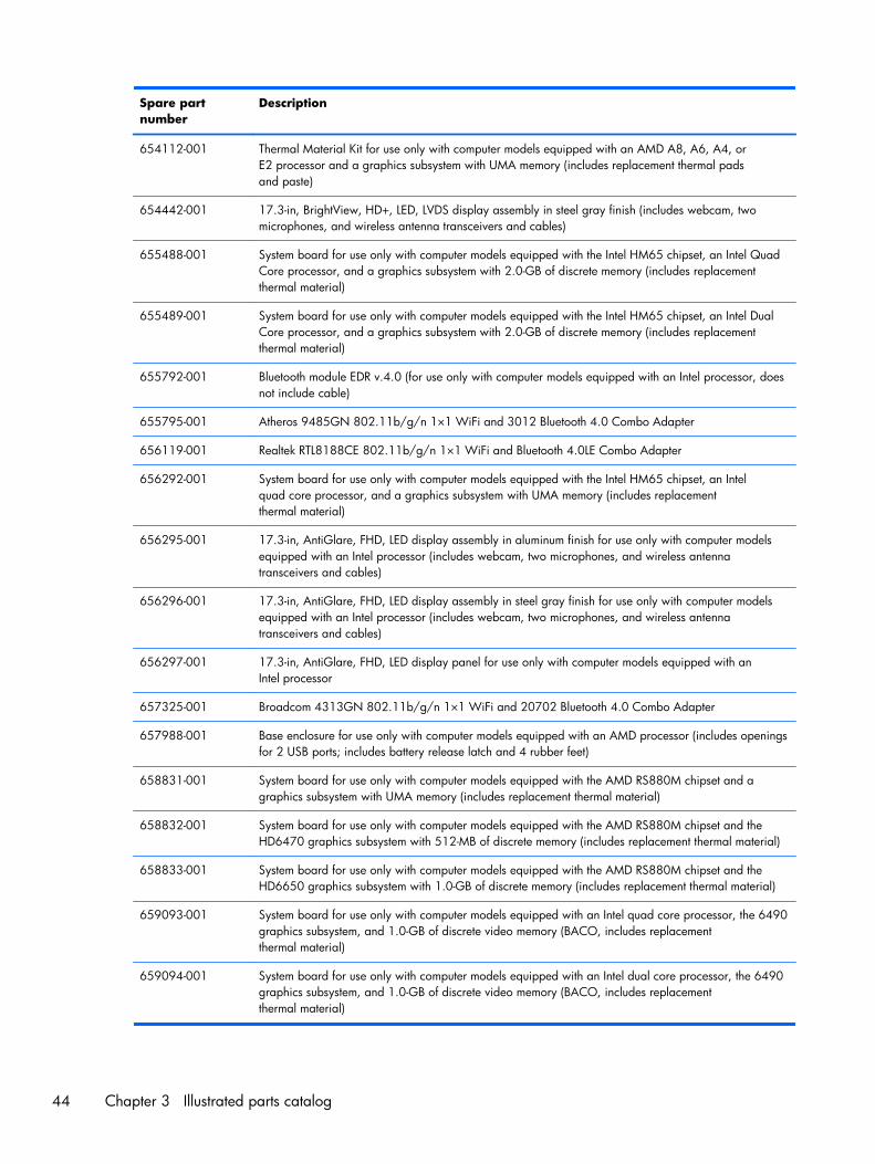
Spare partnumber
Description
654112-001 Thermal Material Kit for use only with computer models equipped with an AMD A8, A6, A4, orE2 processor and a graphics subsystem with UMA memory (includes replacement thermal padsand paste)
654442-001 17.3-in, BrightView, HD+, LED, LVDS display assembly in steel gray finish (includes webcam, twomicrophones, and wireless antenna transceivers and cables)
655488-001 System board for use only with computer models equipped with the Intel HM65 chipset, an Intel QuadCore processor, and a graphics subsystem with 2.0-GB of discrete memory (includes replacementthermal material)
655489-001 System board for use only with computer models equipped with the Intel HM65 chipset, an Intel DualCore processor, and a graphics subsystem with 2.0-GB of discrete memory (includes replacementthermal material)
655792-001 Bluetooth module EDR v.4.0 (for use only with computer models equipped with an Intel processor, doesnot include cable)
655795-001 Atheros 9485GN 802.11b/g/n 1×1 WiFi and 3012 Bluetooth 4.0 Combo Adapter
656119-001 Realtek RTL8188CE 802.11b/g/n 1×1 WiFi and Bluetooth 4.0LE Combo Adapter
656292-001 System board for use only with computer models equipped with the Intel HM65 chipset, an Intelquad core processor, and a graphics subsystem with UMA memory (includes replacementthermal material)
656295-001 17.3-in, AntiGlare, FHD, LED display assembly in aluminum finish for use only with computer modelsequipped with an Intel processor (includes webcam, two microphones, and wireless antennatransceivers and cables)
656296-001 17.3-in, AntiGlare, FHD, LED display assembly in steel gray finish for use only with computer modelsequipped with an Intel processor (includes webcam, two microphones, and wireless antennatransceivers and cables)
656297-001 17.3-in, AntiGlare, FHD, LED display panel for use only with computer models equipped with anIntel processor
657325-001 Broadcom 4313GN 802.11b/g/n 1×1 WiFi and 20702 Bluetooth 4.0 Combo Adapter
657988-001 Base enclosure for use only with computer models equipped with an AMD processor (includes openingsfor 2 USB ports; includes battery release latch and 4 rubber feet)
658831-001 System board for use only with computer models equipped with the AMD RS880M chipset and agraphics subsystem with UMA memory (includes replacement thermal material)
658832-001 System board for use only with computer models equipped with the AMD RS880M chipset and theHD6470 graphics subsystem with 512-MB of discrete memory (includes replacement thermal material)
658833-001 System board for use only with computer models equipped with the AMD RS880M chipset and theHD6650 graphics subsystem with 1.0-GB of discrete memory (includes replacement thermal material)
659093-001 System board for use only with computer models equipped with an Intel quad core processor, the 6490graphics subsystem, and 1.0-GB of discrete video memory (BACO, includes replacementthermal material)
659094-001 System board for use only with computer models equipped with an Intel dual core processor, the 6490graphics subsystem, and 1.0-GB of discrete video memory (BACO, includes replacementthermal material)
44 Chapter 3 Illustrated parts catalog
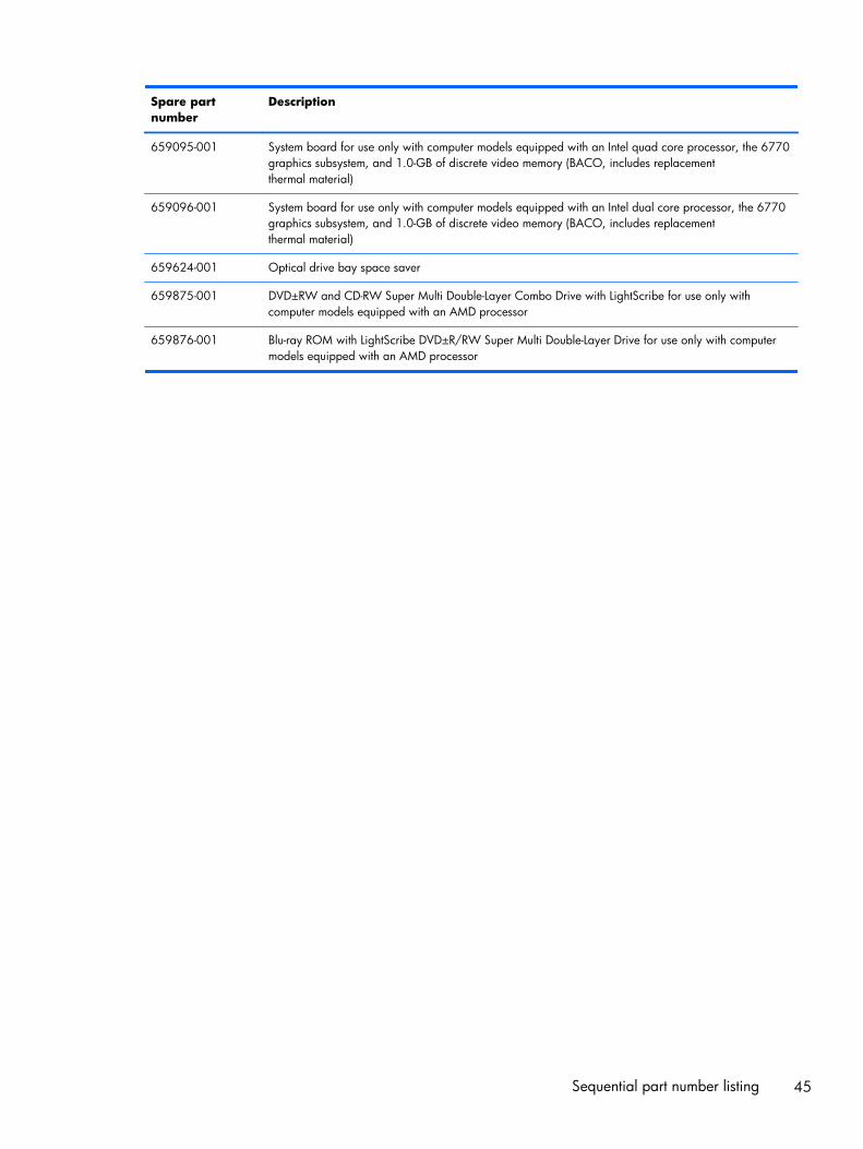
Spare partnumber
Description
659095-001 System board for use only with computer models equipped with an Intel quad core processor, the 6770graphics subsystem, and 1.0-GB of discrete video memory (BACO, includes replacementthermal material)
659096-001 System board for use only with computer models equipped with an Intel dual core processor, the 6770graphics subsystem, and 1.0-GB of discrete video memory (BACO, includes replacementthermal material)
659624-001 Optical drive bay space saver
659875-001 DVD±RW and CD-RW Super Multi Double-Layer Combo Drive with LightScribe for use only withcomputer models equipped with an AMD processor
659876-001 Blu-ray ROM with LightScribe DVD±R/RW Super Multi Double-Layer Drive for use only with computermodels equipped with an AMD processor
Sequential part number listing 45
4 Removal and replacementprocedures
Preliminary replacement requirements
Tools required
You will need the following tools to complete the removal and replacement procedures:
● Flat-bladed screwdriver
● Magnetic screwdriver
● Phillips P0 and P1 screwdrivers
Service considerations
The following sections include some of the considerations that you must keep in mind duringdisassembly and assembly procedures.
NOTE: As you remove each subassembly from the computer, place the subassembly (and allaccompanying screws) away from the work area to prevent damage.
Plastic parts
CAUTION: Using excessive force during disassembly and reassembly can damage plastic parts. Usecare when handling the plastic parts. Apply pressure only at the points designated in themaintenance instructions.
Cables and connectors
CAUTION: When servicing the computer, be sure that cables are placed in their proper locationsduring the reassembly process. Improper cable placement can damage the computer.
Cables must be handled with extreme care to avoid damage. Apply only the tension required to unseator seat the cables during removal and insertion. Handle cables by the connector whenever possible. Inall cases, avoid bending, twisting, or tearing cables. Be sure that cables are routed in such a way thatthey cannot be caught or snagged by parts being removed or replaced. Handle flex cables withextreme care; these cables tear easily.
46 Chapter 4 Removal and replacement procedures
Drive handling
CAUTION: Drives are fragile components that must be handled with care. To prevent damage tothe computer, damage to a drive, or loss of information, observe these precautions:
Before removing or inserting a hard drive, shut down the computer. If you are unsure whetherthe computer is off or in Hibernation, turn the computer on, and then shut it down through theoperating system.
Before handling a drive, be sure that you are discharged of static electricity. While handling a drive,avoid touching the connector.
Before removing a diskette drive or optical drive, be sure that a diskette or disc is not in the drive andbe sure that the optical drive tray is closed.
Handle drives on surfaces covered with at least one inch of shock-proof foam.
Avoid dropping drives from any height onto any surface.
After removing a hard drive, an optical drive, or a diskette drive, place it in a static-proof bag.
Avoid exposing an internal hard drive to products that have magnetic fields, such as monitorsor speakers.
Avoid exposing a drive to temperature extremes or liquids.
If a drive must be mailed, place the drive in a bubble pack mailer or other suitable form of protectivepackaging and label the package “FRAGILE.”
Grounding guidelines
Electrostatic discharge damage
Electronic components are sensitive to electrostatic discharge (ESD). Circuitry design and structuredetermine the degree of sensitivity. Networks built into many integrated circuits provide someprotection, but in many cases, ESD contains enough power to alter device parameters or meltsilicon junctions.
A discharge of static electricity from a finger or other conductor can destroy static-sensitive devices ormicrocircuitry. Even if the spark is neither felt nor heard, damage may have occurred.
An electronic device exposed to ESD may not be affected at all and can work perfectly throughout anormal cycle. Or the device may function normally for a while, then degrade in the internal layers,reducing its life expectancy.
Preliminary replacement requirements 47
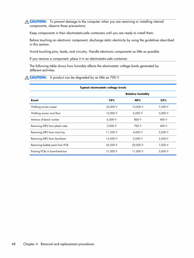
CAUTION: To prevent damage to the computer when you are removing or installing internalcomponents, observe these precautions:
Keep components in their electrostatic-safe containers until you are ready to install them.
Before touching an electronic component, discharge static electricity by using the guidelines describedin this section.
Avoid touching pins, leads, and circuitry. Handle electronic components as little as possible.
If you remove a component, place it in an electrostatic-safe container.
The following table shows how humidity affects the electrostatic voltage levels generated bydifferent activities.
CAUTION: A product can be degraded by as little as 700 V.
Typical electrostatic voltage levels
Relative humidity
Event 10% 40% 55%
Walking across carpet 35,000 V 15,000 V 7,500 V
Walking across vinyl floor 12,000 V 5,000 V 3,000 V
Motions of bench worker 6,000 V 800 V 400 V
Removing DIPS from plastic tube 2,000 V 700 V 400 V
Removing DIPS from vinyl tray 11,500 V 4,000 V 2,000 V
Removing DIPS from Styrofoam 14,500 V 5,000 V 3,500 V
Removing bubble pack from PCB 26,500 V 20,000 V 7,000 V
Packing PCBs in foam-lined box 21,000 V 11,000 V 5,000 V
48 Chapter 4 Removal and replacement procedures
Packaging and transporting guidelines
Follow these grounding guidelines when packaging and transporting equipment:
● To avoid hand contact, transport products in static-safe tubes, bags, or boxes.
● Protect ESD-sensitive parts and assemblies with conductive or approved containers or packaging.
● Keep ESD-sensitive parts in their containers until the parts arrive at static-free workstations.
● Place items on a grounded surface before removing items from their containers.
● Always be properly grounded when touching a component or assembly.
● Store reusable ESD-sensitive parts from assemblies in protective packaging ornonconductive foam.
● Use transporters and conveyors made of antistatic belts and roller bushings. Be sure thatmechanized equipment used for moving materials is wired to ground and that proper materialsare selected to avoid static charging. When grounding is not possible, use an ionizer to dissipateelectric charges.
Workstation guidelines
Follow these grounding workstation guidelines:
● Cover the workstation with approved static-shielding material.
● Use a wrist strap connected to a properly grounded work surface and use properly grounded toolsand equipment.
● Use conductive field service tools, such as cutters, screwdrivers, and vacuums.
● When fixtures must directly contact dissipative surfaces, use fixtures made only of static-safe materials.
● Keep the work area free of nonconductive materials, such as ordinary plastic assembly aidsand Styrofoam.
● Handle ESD-sensitive components, parts, and assemblies by the case or PCM laminate. Handlethese items only at static-free workstations.
● Avoid contact with pins, leads, or circuitry.
● Turn off power and input signals before inserting or removing connectors or test equipment.
Preliminary replacement requirements 49
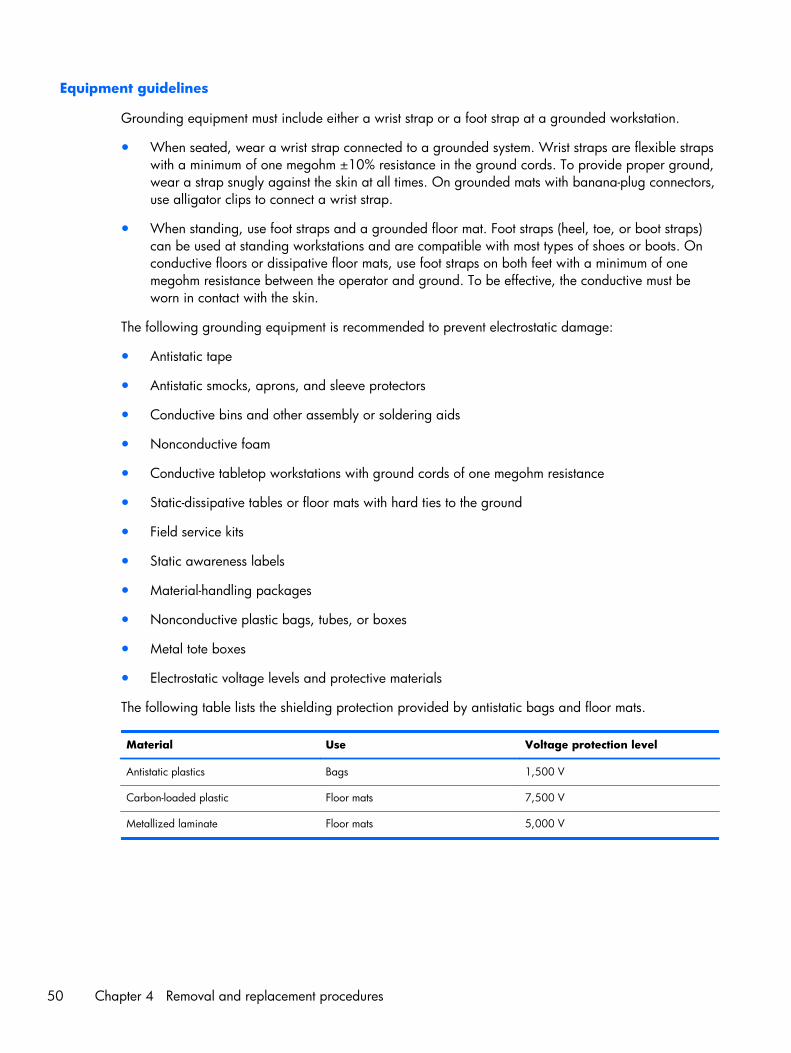
Equipment guidelines
Grounding equipment must include either a wrist strap or a foot strap at a grounded workstation.
● When seated, wear a wrist strap connected to a grounded system. Wrist straps are flexible strapswith a minimum of one megohm ±10% resistance in the ground cords. To provide proper ground,wear a strap snugly against the skin at all times. On grounded mats with banana-plug connectors,use alligator clips to connect a wrist strap.
● When standing, use foot straps and a grounded floor mat. Foot straps (heel, toe, or boot straps)can be used at standing workstations and are compatible with most types of shoes or boots. Onconductive floors or dissipative floor mats, use foot straps on both feet with a minimum of onemegohm resistance between the operator and ground. To be effective, the conductive must beworn in contact with the skin.
The following grounding equipment is recommended to prevent electrostatic damage:
● Antistatic tape
● Antistatic smocks, aprons, and sleeve protectors
● Conductive bins and other assembly or soldering aids
● Nonconductive foam
● Conductive tabletop workstations with ground cords of one megohm resistance
● Static-dissipative tables or floor mats with hard ties to the ground
● Field service kits
● Static awareness labels
● Material-handling packages
● Nonconductive plastic bags, tubes, or boxes
● Metal tote boxes
● Electrostatic voltage levels and protective materials
The following table lists the shielding protection provided by antistatic bags and floor mats.
Material Use Voltage protection level
Antistatic plastics Bags 1,500 V
Carbon-loaded plastic Floor mats 7,500 V
Metallized laminate Floor mats 5,000 V
50 Chapter 4 Removal and replacement procedures
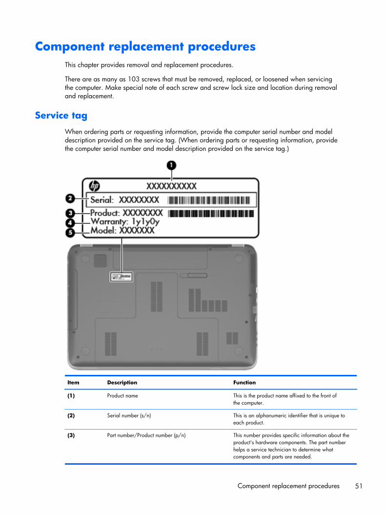
Component replacement proceduresThis chapter provides removal and replacement procedures.
There are as many as 103 screws that must be removed, replaced, or loosened when servicingthe computer. Make special note of each screw and screw lock size and location during removaland replacement.
Service tag
When ordering parts or requesting information, provide the computer serial number and modeldescription provided on the service tag. (When ordering parts or requesting information, providethe computer serial number and model description provided on the service tag.)
Item Description Function
(1) Product name This is the product name affixed to the front ofthe computer.
(2) Serial number (s/n) This is an alphanumeric identifier that is unique toeach product.
(3) Part number/Product number (p/n) This number provides specific information about theproduct's hardware components. The part numberhelps a service technician to determine whatcomponents and parts are needed.
Component replacement procedures 51
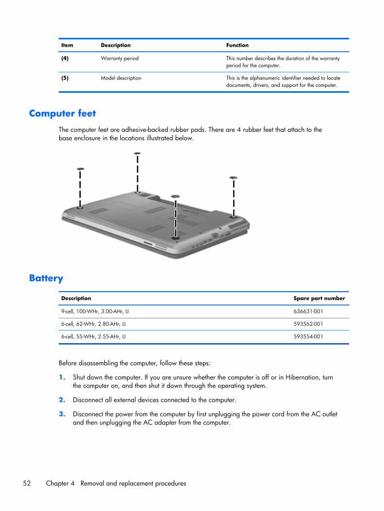
Item Description Function
(4) Warranty period This number describes the duration of the warrantyperiod for the computer.
(5) Model description This is the alphanumeric identifier needed to locatedocuments, drivers, and support for the computer.
Computer feet
The computer feet are adhesive-backed rubber pads. There are 4 rubber feet that attach to thebase enclosure in the locations illustrated below.
Battery
Description Spare part number
9-cell, 100-WHr, 3.00-AHr, LI 636631-001
6-cell, 62-WHr, 2.80-AHr, LI 593562-001
6-cell, 55-WHr, 2.55-AHr, LI 593554-001
Before disassembling the computer, follow these steps:
1. Shut down the computer. If you are unsure whether the computer is off or in Hibernation, turnthe computer on, and then shut it down through the operating system.
2. Disconnect all external devices connected to the computer.
3. Disconnect the power from the computer by first unplugging the power cord from the AC outletand then unplugging the AC adapter from the computer.
52 Chapter 4 Removal and replacement procedures
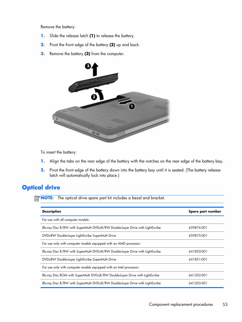
Remove the battery:
1. Slide the release latch (1) to release the battery.
2. Pivot the front edge of the battery (2) up and back.
3. Remove the battery (3) from the computer.
To insert the battery:
1. Align the tabs on the rear edge of the battery with the notches on the rear edge of the battery bay.
2. Pivot the front edge of the battery down into the battery bay until it is seated. (The battery releaselatch will automatically lock into place.)
Optical drive
NOTE: The optical drive spare part kit includes a bezel and bracket.
Description Spare part number
For use with all computer models:
Blu-ray Disc R/RW with SuperMulti DVD±R/RW Double-Layer Drive with LightScribe 659876-001
DVD±RW Double-Layer LightScribe SuperMulti Drive 659875-001
For use only with computer models equipped with an AMD processor:
Blu-ray Disc R/RW with SuperMulti DVD±R/RW Double-Layer Drive with LightScribe 641850-001
DVD±RW Double-Layer LightScribe SuperMulti Drive 641851-001
For use only with computer models equipped with an Intel processor:
Blu-ray Disc ROM with SuperMulti DVD±R/RW Double-Layer Drive with LightScribe 641302-001
Blu-ray Disc R/RW with SuperMulti DVD±R/RW Double-Layer Drive with LightScribe 641303-001
Component replacement procedures 53
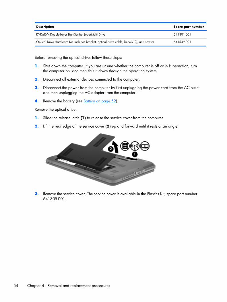
Description Spare part number
DVD±RW Double-Layer LightScribe SuperMulti Drive 641301-001
Optical Drive Hardware Kit (includes bracket, optical drive cable, bezels (2), and screws 641549-001
Before removing the optical drive, follow these steps:
1. Shut down the computer. If you are unsure whether the computer is off or in Hibernation, turnthe computer on, and then shut it down through the operating system.
2. Disconnect all external devices connected to the computer.
3. Disconnect the power from the computer by first unplugging the power cord from the AC outletand then unplugging the AC adapter from the computer.
4. Remove the battery (see Battery on page 52).
Remove the optical drive:
1. Slide the release latch (1) to release the service cover from the computer.
2. Lift the rear edge of the service cover (2) up and forward until it rests at an angle.
3. Remove the service cover. The service cover is available in the Plastics Kit, spare part number641305-001.
54 Chapter 4 Removal and replacement procedures
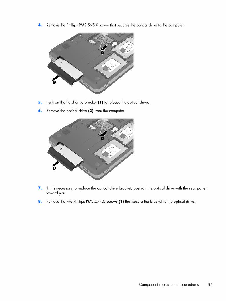
4. Remove the Phillips PM2.5×5.0 screw that secures the optical drive to the computer.
5. Push on the hard drive bracket (1) to release the optical drive.
6. Remove the optical drive (2) from the computer.
7. If it is necessary to replace the optical drive bracket, position the optical drive with the rear paneltoward you.
8. Remove the two Phillips PM2.0×4.0 screws (1) that secure the bracket to the optical drive.
Component replacement procedures 55
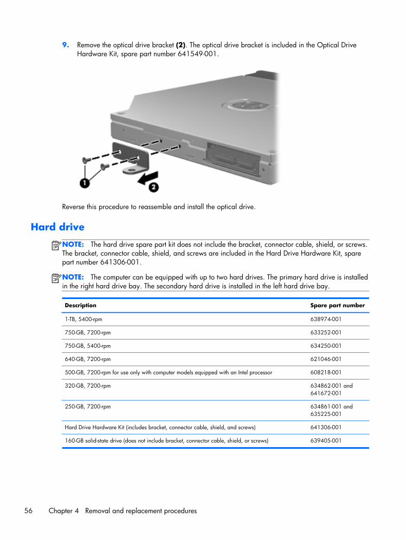
9. Remove the optical drive bracket (2). The optical drive bracket is included in the Optical DriveHardware Kit, spare part number 641549-001.
Reverse this procedure to reassemble and install the optical drive.
Hard drive
NOTE: The hard drive spare part kit does not include the bracket, connector cable, shield, or screws.The bracket, connector cable, shield, and screws are included in the Hard Drive Hardware Kit, sparepart number 641306-001.
NOTE: The computer can be equipped with up to two hard drives. The primary hard drive is installedin the right hard drive bay. The secondary hard drive is installed in the left hard drive bay.
Description Spare part number
1-TB, 5400-rpm 638974-001
750-GB, 7200-rpm 633252-001
750-GB, 5400-rpm 634250-001
640-GB, 7200-rpm 621046-001
500-GB, 7200-rpm for use only with computer models equipped with an Intel processor 608218-001
320-GB, 7200-rpm 634862-001 and641672-001
250-GB, 7200-rpm 634861-001 and635225-001
Hard Drive Hardware Kit (includes bracket, connector cable, shield, and screws) 641306-001
160-GB solid-state drive (does not include bracket, connector cable, shield, or screws) 639405-001
56 Chapter 4 Removal and replacement procedures
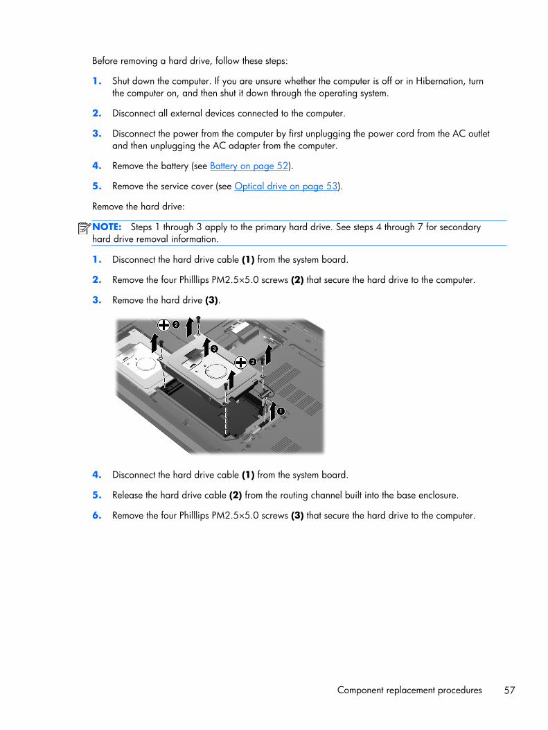
Before removing a hard drive, follow these steps:
1. Shut down the computer. If you are unsure whether the computer is off or in Hibernation, turnthe computer on, and then shut it down through the operating system.
2. Disconnect all external devices connected to the computer.
3. Disconnect the power from the computer by first unplugging the power cord from the AC outletand then unplugging the AC adapter from the computer.
4. Remove the battery (see Battery on page 52).
5. Remove the service cover (see Optical drive on page 53).
Remove the hard drive:
NOTE: Steps 1 through 3 apply to the primary hard drive. See steps 4 through 7 for secondaryhard drive removal information.
1. Disconnect the hard drive cable (1) from the system board.
2. Remove the four Philllips PM2.5×5.0 screws (2) that secure the hard drive to the computer.
3. Remove the hard drive (3).
4. Disconnect the hard drive cable (1) from the system board.
5. Release the hard drive cable (2) from the routing channel built into the base enclosure.
6. Remove the four Philllips PM2.5×5.0 screws (3) that secure the hard drive to the computer.
Component replacement procedures 57
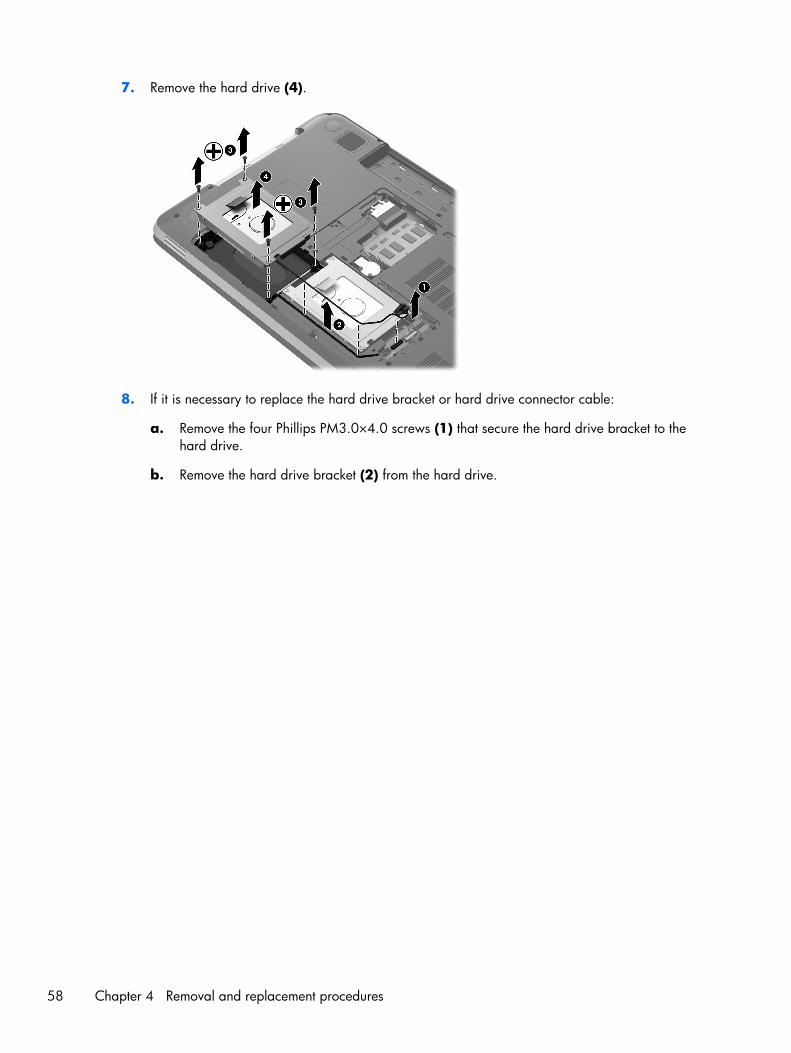
7. Remove the hard drive (4).
8. If it is necessary to replace the hard drive bracket or hard drive connector cable:
a. Remove the four Phillips PM3.0×4.0 screws (1) that secure the hard drive bracket to thehard drive.
b. Remove the hard drive bracket (2) from the hard drive.
58 Chapter 4 Removal and replacement procedures
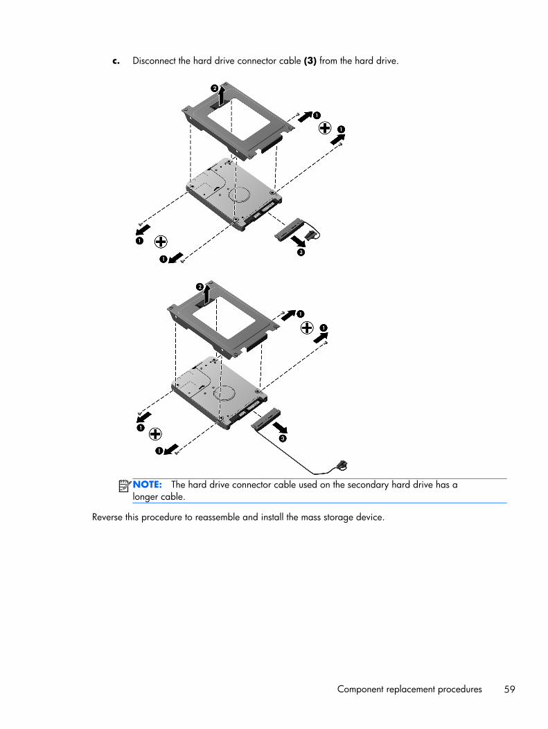
c. Disconnect the hard drive connector cable (3) from the hard drive.
NOTE: The hard drive connector cable used on the secondary hard drive has alonger cable.
Reverse this procedure to reassemble and install the mass storage device.
Component replacement procedures 59
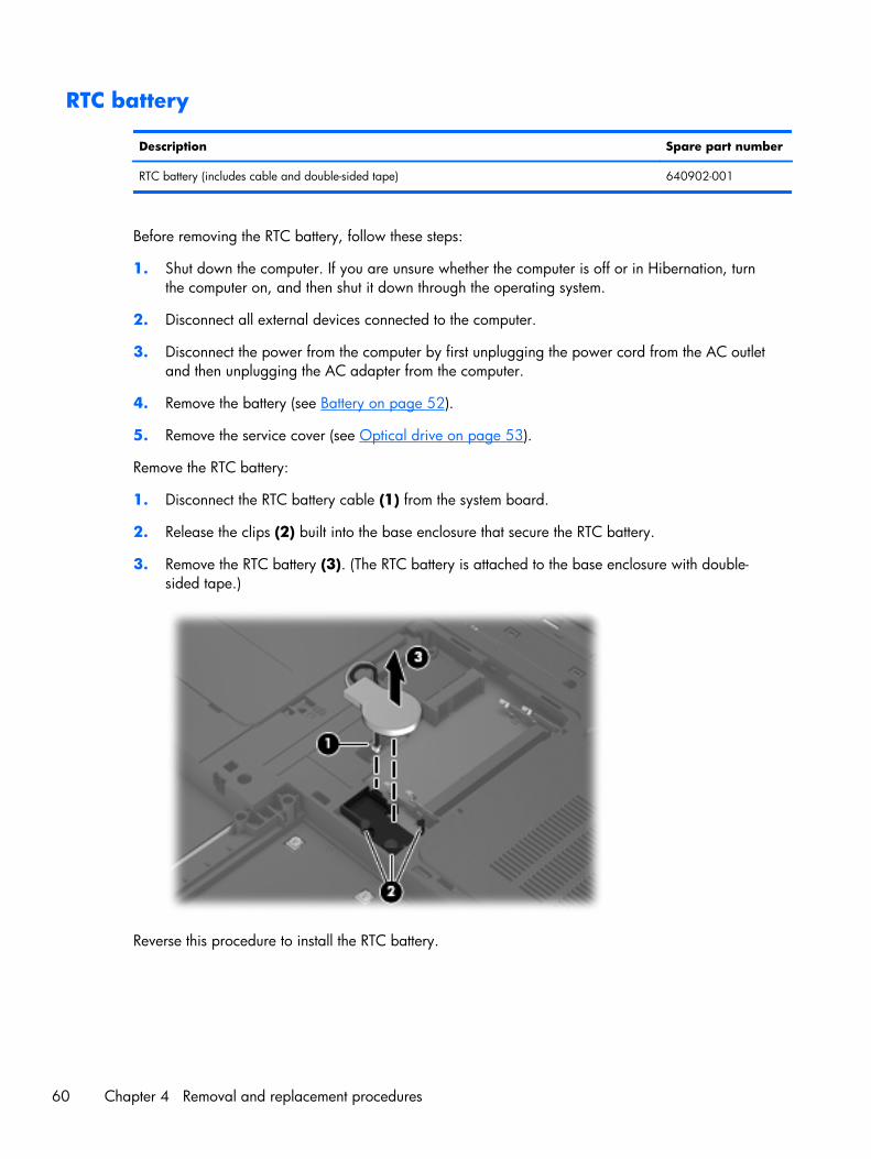
RTC battery
Description Spare part number
RTC battery (includes cable and double-sided tape) 640902-001
Before removing the RTC battery, follow these steps:
1. Shut down the computer. If you are unsure whether the computer is off or in Hibernation, turnthe computer on, and then shut it down through the operating system.
2. Disconnect all external devices connected to the computer.
3. Disconnect the power from the computer by first unplugging the power cord from the AC outletand then unplugging the AC adapter from the computer.
4. Remove the battery (see Battery on page 52).
5. Remove the service cover (see Optical drive on page 53).
Remove the RTC battery:
1. Disconnect the RTC battery cable (1) from the system board.
2. Release the clips (2) built into the base enclosure that secure the RTC battery.
3. Remove the RTC battery (3). (The RTC battery is attached to the base enclosure with double-sided tape.)
Reverse this procedure to install the RTC battery.
60 Chapter 4 Removal and replacement procedures
Memory module
NOTE: The computer can be equipped with up to two memory modules. The primary memory moduleis installed in the memory module socket closest to the system board. The expansion memory module isinstalled in the memory module socket farthest from the system board.
Description Spare part number
8 GB (DDR3, 10600, 1333-MHz, for use only with computer models equipped with anIntel processor)
634091-001
4 GB (DDR3, 10600, 1333-MHz) 621569-001
2 GB (DDR3, 10600, 1333-MHz) 621565-001
1 GB (DDR3, 10600, 1333-MHz) 639736-001
Before removing a memory module, follow these steps:
1. Shut down the computer. If you are unsure whether the computer is off or in Hibernation, turnthe computer on, and then shut it down through the operating system.
2. Disconnect all external devices connected to the computer.
3. Disconnect the power from the computer by first unplugging the power cord from the AC outletand then unplugging the AC adapter from the computer.
4. Remove the battery (see Battery on page 52).
5. Remove the service cover (see Optical drive on page 53).
Remove the memory module:
1. Spread the retaining tabs (1) on each side of the memory module slot to releasethe memory module. (The memory module tilts up.)
Component replacement procedures 61
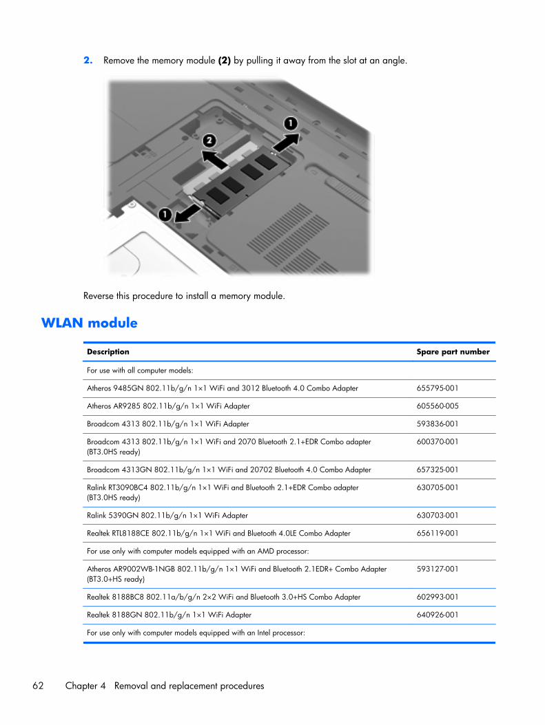
2. Remove the memory module (2) by pulling it away from the slot at an angle.
Reverse this procedure to install a memory module.
WLAN module
Description Spare part number
For use with all computer models:
Atheros 9485GN 802.11b/g/n 1×1 WiFi and 3012 Bluetooth 4.0 Combo Adapter 655795-001
Atheros AR9285 802.11b/g/n 1×1 WiFi Adapter 605560-005
Broadcom 4313 802.11b/g/n 1×1 WiFi Adapter 593836-001
Broadcom 4313 802.11b/g/n 1×1 WiFi and 2070 Bluetooth 2.1+EDR Combo adapter(BT3.0HS ready)
600370-001
Broadcom 4313GN 802.11b/g/n 1×1 WiFi and 20702 Bluetooth 4.0 Combo Adapter 657325-001
Ralink RT3090BC4 802.11b/g/n 1×1 WiFi and Bluetooth 2.1+EDR Combo adapter(BT3.0HS ready)
630705-001
Ralink 5390GN 802.11b/g/n 1×1 WiFi Adapter 630703-001
Realtek RTL8188CE 802.11b/g/n 1×1 WiFi and Bluetooth 4.0LE Combo Adapter 656119-001
For use only with computer models equipped with an AMD processor:
Atheros AR9002WB-1NGB 802.11b/g/n 1×1 WiFi and Bluetooth 2.1EDR+ Combo Adapter(BT3.0+HS ready)
593127-001
Realtek 8188BC8 802.11a/b/g/n 2×2 WiFi and Bluetooth 3.0+HS Combo Adapter 602993-001
Realtek 8188GN 802.11b/g/n 1×1 WiFi Adapter 640926-001
For use only with computer models equipped with an Intel processor:
62 Chapter 4 Removal and replacement procedures
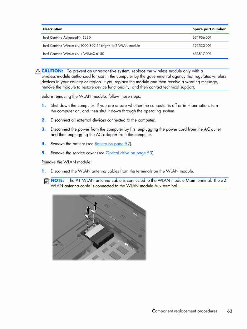
Description Spare part number
Intel Centrino Advanced-N 6230 631956-001
Intel Centrino Wireless-N 1000 802.11b/g/n 1×2 WLAN module 593530-001
Intel Centrino Wireless-N + WiMAX 6150 633817-001
CAUTION: To prevent an unresponsive system, replace the wireless module only with awireless module authorized for use in the computer by the governmental agency that regulates wirelessdevices in your country or region. If you replace the module and then receive a warning message,remove the module to restore device functionality, and then contact technical support.
Before removing the WLAN module, follow these steps:
1. Shut down the computer. If you are unsure whether the computer is off or in Hibernation, turnthe computer on, and then shut it down through the operating system.
2. Disconnect all external devices connected to the computer.
3. Disconnect the power from the computer by first unplugging the power cord from the AC outletand then unplugging the AC adapter from the computer.
4. Remove the battery (see Battery on page 52).
5. Remove the service cover (see Optical drive on page 53).
Remove the WLAN module:
1. Disconnect the WLAN antenna cables from the terminals on the WLAN module.
NOTE: The #1 WLAN antenna cable is connected to the WLAN module Main terminal. The #2WLAN antenna cable is connected to the WLAN module Aux terminal.
Component replacement procedures 63
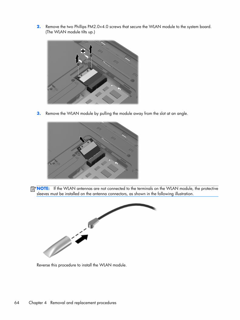
2. Remove the two Phillips PM2.0×4.0 screws that secure the WLAN module to the system board.(The WLAN module tilts up.)
3. Remove the WLAN module by pulling the module away from the slot at an angle.
NOTE: If the WLAN antennas are not connected to the terminals on the WLAN module, the protectivesleeves must be installed on the antenna connectors, as shown in the following illustration.
Reverse this procedure to install the WLAN module.
64 Chapter 4 Removal and replacement procedures
Keyboard
NOTE: The keyboard spare part kit includes a keyboard cable.
Description Spare part number Description Spare part number
For use with all computer models: For use in Italy 639396-061
For use in Belgium 639396-A41 For use in the Netherlands 639396-B31
For use in Canada 639396-121 For use in Portugal 639396-131
For use in the Czech Republic 639396-221 For use in Russia 639396-251
For use in Denmark, Finland,and Norway
639396-DH1 For use in Slovenia 639396-BA1
For use in France 639396-051 For use in Spain 639396-071
For use in Germany 639396-041 For use in Switzerland 639396-BG1
For use in Greece 639396-DJ1 For use in the United Kingdomand Singapore
639396-031
For use in Hungary 639396-211 For use in the United States 639396-001
For use only with computer models equipped with anIntel processor:
For use in Saudi Arabia 639396-171
For use in Bulgaria 639396-261 For use in South Korea 639396-AD1
For use in India 639396-D61 For use in Taiwan 639396-AB1
For use in Israel 639396-BB1 For use in Thailand 639396-281
For use in Japan 639396-291 For use in Turkey 639396-141
Before removing the keyboard, follow these steps:
1. Shut down the computer. If you are unsure whether the computer is off or in Hibernation, turnthe computer on, and then shut it down through the operating system.
2. Disconnect all external devices connected to the computer.
3. Disconnect the power from the computer by first unplugging the power cord from the AC outletand then unplugging the AC adapter from the computer.
4. Remove the battery (see Battery on page 52).
5. Remove the optical drive (see Optical drive on page 53).
Component replacement procedures 65
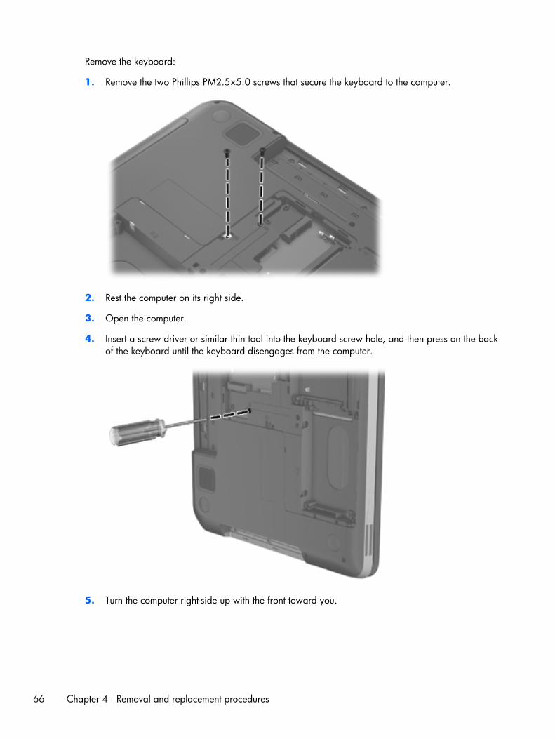
Remove the keyboard:
1. Remove the two Phillips PM2.5×5.0 screws that secure the keyboard to the computer.
2. Rest the computer on its right side.
3. Open the computer.
4. Insert a screw driver or similar thin tool into the keyboard screw hole, and then press on the backof the keyboard until the keyboard disengages from the computer.
5. Turn the computer right-side up with the front toward you.
66 Chapter 4 Removal and replacement procedures
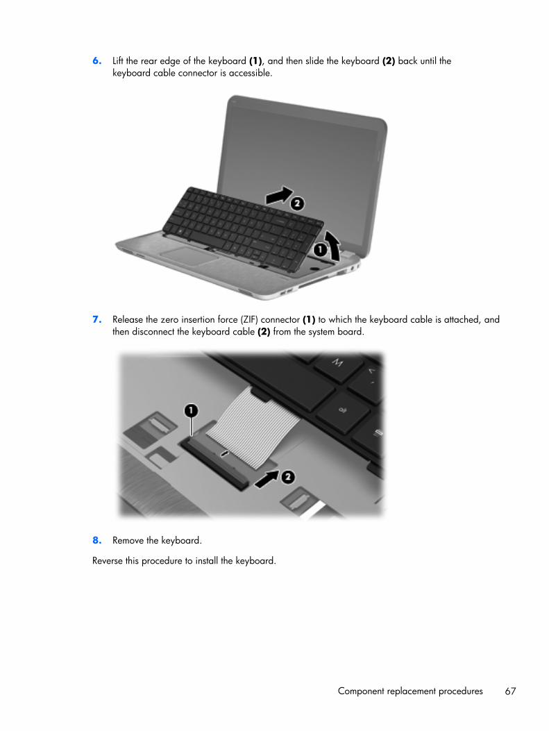
6. Lift the rear edge of the keyboard (1), and then slide the keyboard (2) back until thekeyboard cable connector is accessible.
7. Release the zero insertion force (ZIF) connector (1) to which the keyboard cable is attached, andthen disconnect the keyboard cable (2) from the system board.
8. Remove the keyboard.
Reverse this procedure to install the keyboard.
Component replacement procedures 67
Top cover
NOTE: The top cover spare part kit includes the TouchPad and TouchPad cable and TouchPad buttonboard and TouchPad button board cable.
Description Spare part number
In steel gray finish 649947-001
In regular finish 639388-001
Before removing the top cover, follow these steps:
1. Shut down the computer. If you are unsure whether the computer is off or in Hibernation, turnthe computer on, and then shut it down through the operating system.
2. Disconnect all external devices connected to the computer.
3. Disconnect the power from the computer by first unplugging the power cord from the AC outletand then unplugging the AC adapter from the computer.
4. Remove the battery (see Battery on page 52), and then remove the following components:
● Optical drive (see Optical drive on page 53)
● Hard drive (see Hard drive on page 56)
● Keyboard (see Keyboard on page 65)
When replacing the top cover, be sure that the following components are removed from the defectivetop cover and installed on the replacement top cover:
● Fingerprint reader board and cable (see Fingerprint reader board on page 72)
● Power button board and cable (see Power button board on page 74)
● Display lid switch board and cable (see Display lid switch board on page 76)
Remove the top cover:
1. Close the computer.
2. Turn the computer upside down, with the front toward you.
68 Chapter 4 Removal and replacement procedures

3. Remove the eight Phillips PM2.5×5.0 screws that secure the top cover to the computer.
4. Remove the following screws:
(1) One Phillips PM2.5×7.0 screw in the rear left corner of the base enclosure
(2) Three Philllips PM2.5×3.0 screws in the optical drive bay
(3) Two Phillips PM2.5×9.0 screws on the right side of the base enclosure
5. Turn the computer right-side up, with the front toward you.
6. Open the computer.
Component replacement procedures 69
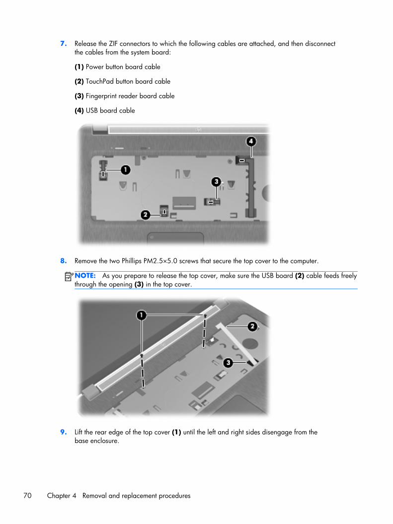
7. Release the ZIF connectors to which the following cables are attached, and then disconnectthe cables from the system board:
(1) Power button board cable
(2) TouchPad button board cable
(3) Fingerprint reader board cable
(4) USB board cable
8. Remove the two Phillips PM2.5×5.0 screws that secure the top cover to the computer.
NOTE: As you prepare to release the top cover, make sure the USB board (2) cable feeds freelythrough the opening (3) in the top cover.
9. Lift the rear edge of the top cover (1) until the left and right sides disengage from thebase enclosure.
70 Chapter 4 Removal and replacement procedures
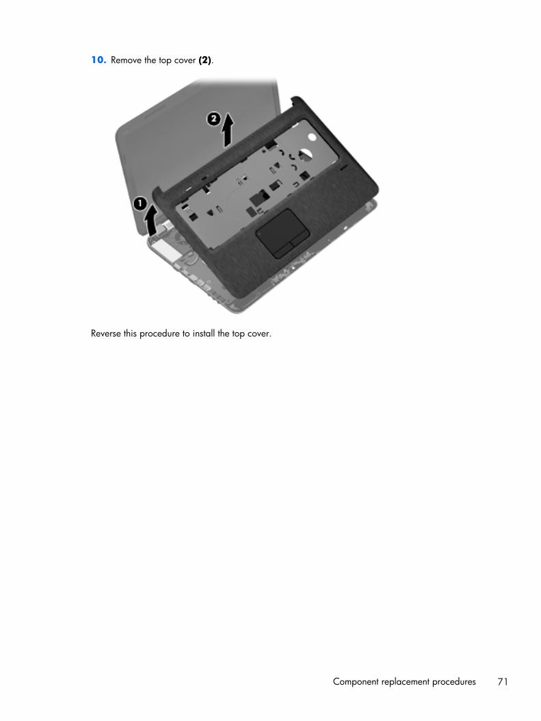
10. Remove the top cover (2).
Reverse this procedure to install the top cover.
Component replacement procedures 71
Fingerprint reader board
NOTE: The fingerprint reader board does not include the fingerprint reader board cable. Thefingerprint reader board cable is included in the Cable Kit, spare part number 639402-001.
Description Spare part number
Fingerprint reader board (includes bracket) 640427-001
Before removing the fingerprint reader board, follow these steps:
1. Shut down the computer. If you are unsure whether the computer is off or in Hibernation, turnthe computer on, and then shut it down through the operating system.
2. Disconnect all external devices connected to the computer.
3. Disconnect the power from the computer by first unplugging the power cord from the AC outletand then unplugging the AC adapter from the computer.
4. Remove the battery (see Battery on page 52), and then remove the following components:
● Optical drive (see Optical drive on page 53)
● Hard drive (see Hard drive on page 56)
● Keyboard (see Keyboard on page 65)
● Top cover (see Top cover on page 68)
Remove the fingerprint reader board, bracket, and cable:
1. Turn the top cover upside down, with the front toward you.
2. Release the fingerprint reader board cable (1) from the surface of the top cover. Remove the twoPhillips PM2.0×2.0 screws (2) that secure the fingerprint reader board and bracket to thetop cover.
72 Chapter 4 Removal and replacement procedures
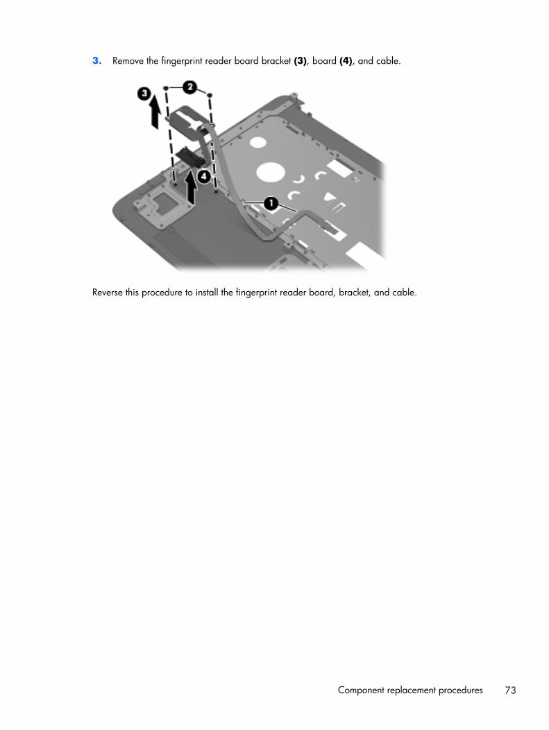
3. Remove the fingerprint reader board bracket (3), board (4), and cable.
Reverse this procedure to install the fingerprint reader board, bracket, and cable.
Component replacement procedures 73
Power button board
NOTE: The power button board does not include the power button board cable. The power buttonboard cable is included in the Cable Kit, spare part number 639402-001.
Description Spare part number
Power button board 640898-001
Before removing the power button board, follow these steps:
1. Shut down the computer. If you are unsure whether the computer is off or in Hibernation, turnthe computer on, and then shut it down through the operating system.
2. Disconnect all external devices connected to the computer.
3. Disconnect the power from the computer by first unplugging the power cord from the AC outletand then unplugging the AC adapter from the computer.
4. Remove the battery (see Battery on page 52), and then remove the following components:
● Optical drive (see Optical drive on page 53)
● Hard drive (see Hard drive on page 56)
● Keyboard (see Keyboard on page 65)
● Top cover (see Top cover on page 68)
Remove the power button board:
1. Turn the top cover upside down, with the front toward you.
2. Release the power button board cable from the tab (1) on the top cover.
3. Disconnect the display lid switch board cable (2) from the power button board.
4. Remove the two Phillips PM2.0×4.0 screws (3) that secure the power button board to thetop cover.
74 Chapter 4 Removal and replacement procedures
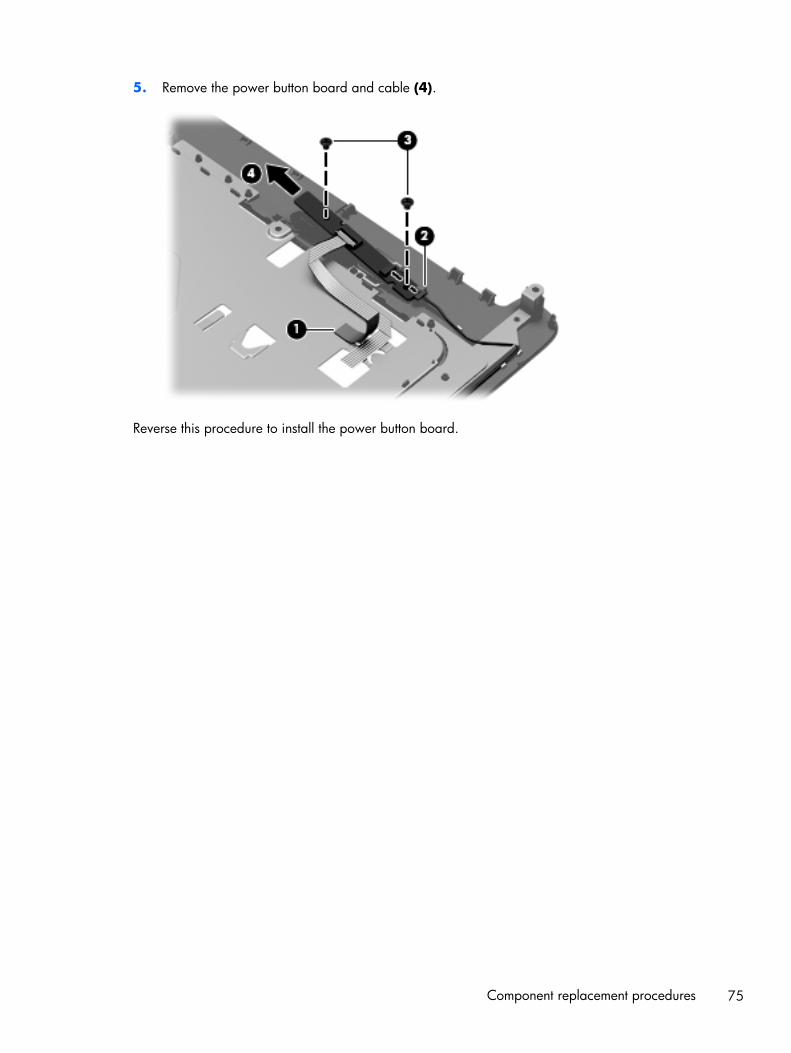
5. Remove the power button board and cable (4).
Reverse this procedure to install the power button board.
Component replacement procedures 75
Display lid switch board
Description Spare part number
Display lid switch board (includes cable) 647270-001
Before removing the display lid switch board, follow these steps:
1. Shut down the computer. If you are unsure whether the computer is off or in Hibernation, turnthe computer on, and then shut it down through the operating system.
2. Disconnect all external devices connected to the computer.
3. Disconnect the power from the computer by first unplugging the power cord from the AC outletand then unplugging the AC adapter from the computer.
4. Remove the battery (see Battery on page 52), and then remove the following components:
● Optical drive (see Optical drive on page 53)
● Hard drive (see Hard drive on page 56)
● Keyboard (see Keyboard on page 65)
● Top cover (see Top cover on page 68)
Remove the display lid switch board:
1. Turn the top cover upside down, with the front toward you.
2. Disconnect the display lid switch cable (1) from the power button board.
3. Release the display lid switch board cable from the clips (2) built into the top cover.
76 Chapter 4 Removal and replacement procedures
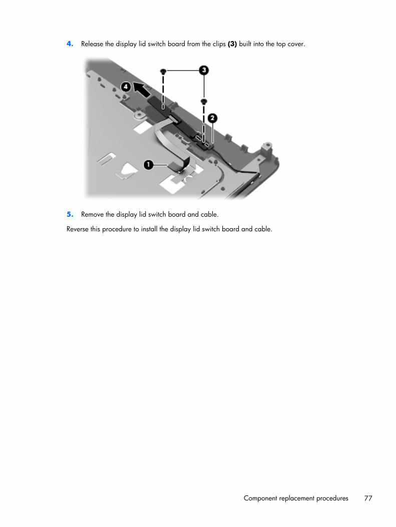
4. Release the display lid switch board from the clips (3) built into the top cover.
5. Remove the display lid switch board and cable.
Reverse this procedure to install the display lid switch board and cable.
Component replacement procedures 77
SD Card reader board
NOTE: The SD Card reader board does not include the SD Card reader board cable. The SD Cardreader board cable is included in the Cable Kit, spare part number 639402-001.
Description Spare part number
SD Card reader board 640899-001
Before removing the SD Card reader board, follow these steps:
1. Shut down the computer. If you are unsure whether the computer is off or in Hibernation, turnthe computer on, and then shut it down through the operating system.
2. Disconnect all external devices connected to the computer.
3. Disconnect the power from the computer by first unplugging the power cord from the AC outletand then unplugging the AC adapter from the computer.
4. Remove the battery (see Battery on page 52), and then remove the following components:
● Optical drive (see Optical drive on page 53)
● Hard drive (see Hard drive on page 56)
● Keyboard (see Keyboard on page 65)
● Top cover (see Top cover on page 68)
Remove the SD Card reader board and cable:
1. Release the ZIF connector to which the SD Card reader board cable is connected, and thendisconnect the SD Card reader board cable (1) from the system board.
2. Remove the two Phillips PM2.5×5.0 screws (2) that secure the SD Card reader board to thebase enclosure.
78 Chapter 4 Removal and replacement procedures
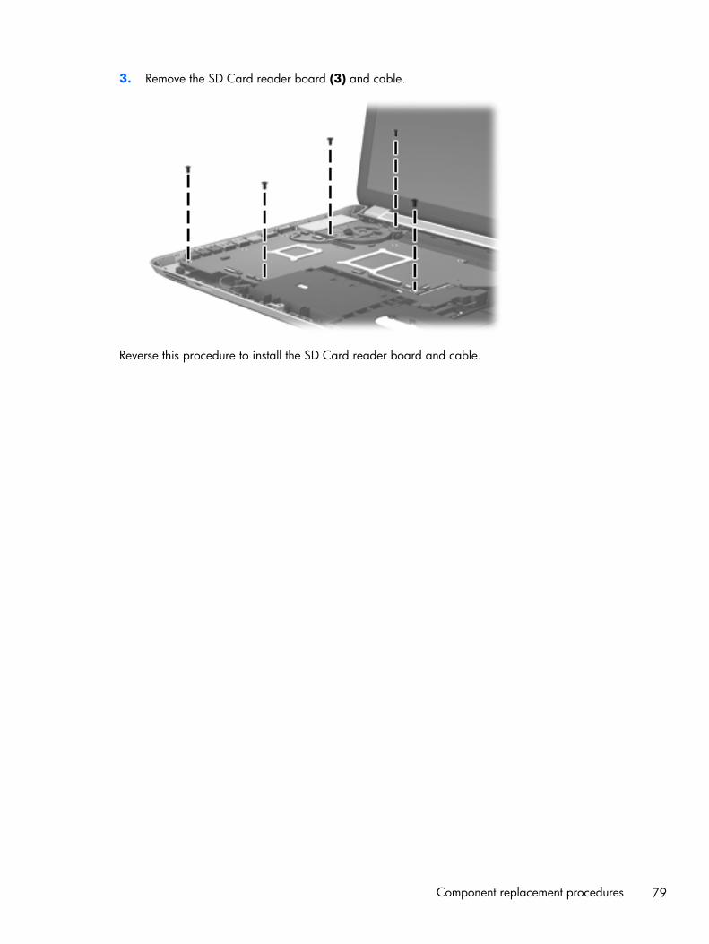
3. Remove the SD Card reader board (3) and cable.
Reverse this procedure to install the SD Card reader board and cable.
Component replacement procedures 79
Bluetooth module
NOTE: This section applies only to computer models equipped with an Intel processor.
NOTE: The Bluetooth module spare part kit does not include the Bluetooth module cable. TheBluetooth module cable is available using spare part number 647271-001.
Description Spare part number
EDR v.4.0 655792-001
EDR v.3.0 537921-001
Before removing the Bluetooth module and cable, follow these steps:
1. Shut down the computer. If you are unsure whether the computer is off or in Hibernation, turnthe computer on, and then shut it down through the operating system.
2. Disconnect all external devices connected to the computer.
3. Disconnect the power from the computer by first unplugging the power cord from the AC outletand then unplugging the AC adapter from the computer.
4. Remove the battery (see Battery on page 52), and then remove the following components:
● Optical drive (see Optical drive on page 53)
● Hard drive (see Hard drive on page 56)
● Keyboard (see Keyboard on page 65)
● Top cover (see Top cover on page 68)
Remove the Bluetooth module and cable:
1. Disconnect the Bluetooth module cable (1) from the system board.
2. Release the Bluetooth module cable (2) from the clips built into the speaker and base enclosure.
80 Chapter 4 Removal and replacement procedures
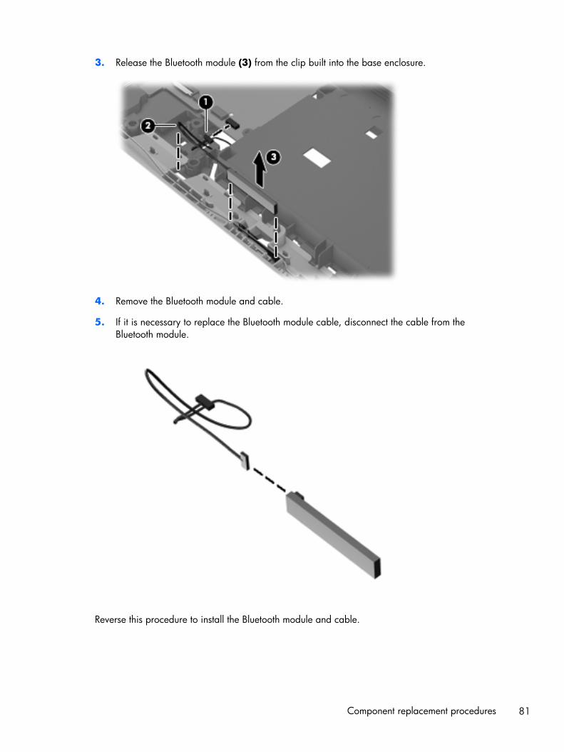
3. Release the Bluetooth module (3) from the clip built into the base enclosure.
4. Remove the Bluetooth module and cable.
5. If it is necessary to replace the Bluetooth module cable, disconnect the cable from theBluetooth module.
Reverse this procedure to install the Bluetooth module and cable.
Component replacement procedures 81
USB board
NOTE: The USB board does not include the USB board cable. The USB board cable is included inthe Cable Kit, spare part number 639402-001.
Description Spare part number
USB board 646434-001
Before removing the USB board, follow these steps:
1. Shut down the computer. If you are unsure whether the computer is off or in Hibernation, turnthe computer on, and then shut it down through the operating system.
2. Disconnect all external devices connected to the computer.
3. Disconnect the power from the computer by first unplugging the power cord from the AC outletand then unplugging the AC adapter from the computer.
4. Remove the battery (see Battery on page 52), and then remove the following components:
● Optical drive (see Optical drive on page 53)
● Hard drive (see Hard drive on page 56)
● Keyboard (see Keyboard on page 65)
● Top cover (see Top cover on page 68)
Remove the USB board:
1. Detach the USB board cable (1) from the base enclosure. (The USB board cable is attached to thebase enclosure with double-sided tape.)
2. Remove the two Phillips PM2.5×5.0 screws (2) that secure the USB board to the base enclosure.
82 Chapter 4 Removal and replacement procedures
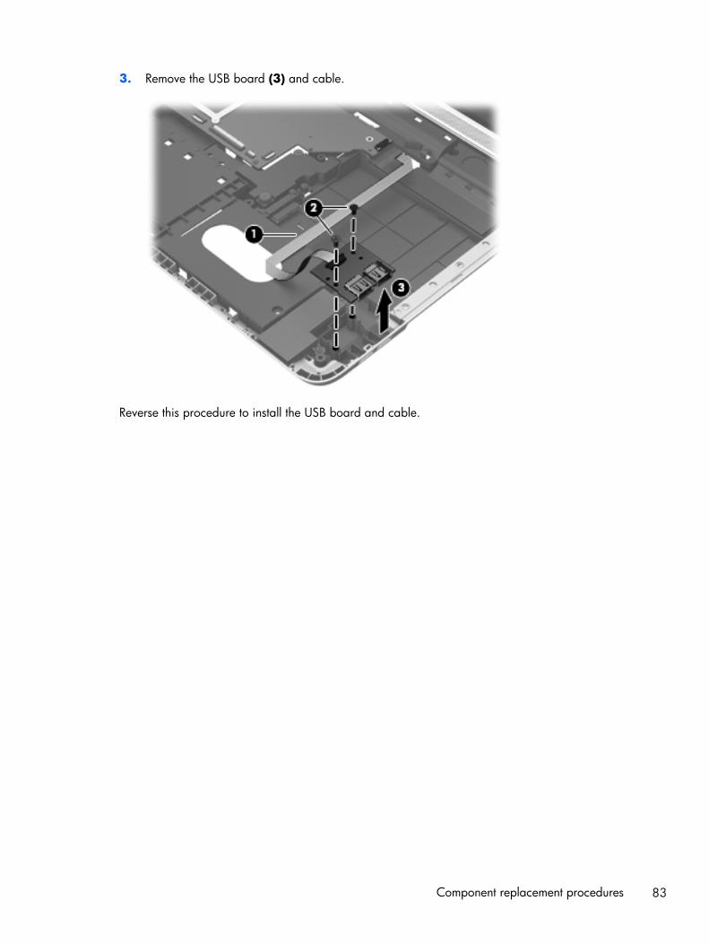
3. Remove the USB board (3) and cable.
Reverse this procedure to install the USB board and cable.
Component replacement procedures 83
Front speakers
Description Spare part number
Front speakers (includes front left and right speakers and cables) 639394-001
Before removing the front speakers, follow these steps:
1. Shut down the computer. If you are unsure whether the computer is off or in Hibernation, turnthe computer on, and then shut it down through the operating system.
2. Disconnect all external devices connected to the computer.
3. Disconnect the power from the computer by first unplugging the power cord from the AC outletand then unplugging the AC adapter from the computer.
4. Remove the battery (see Battery on page 52), and then remove the following components:
● Optical drive (see Optical drive on page 53)
● Hard drive (see Hard drive on page 56)
● Keyboard (see Keyboard on page 65)
● Top cover (see Top cover on page 68)
● USB board (see USB board on page 82)
Remove the front speakers and cables:
1. Disconnect the front speaker cable (1) from the system board.
2. Release the front speaker cable from the clips (2) and routing channel built into thebase enclosure.
84 Chapter 4 Removal and replacement procedures
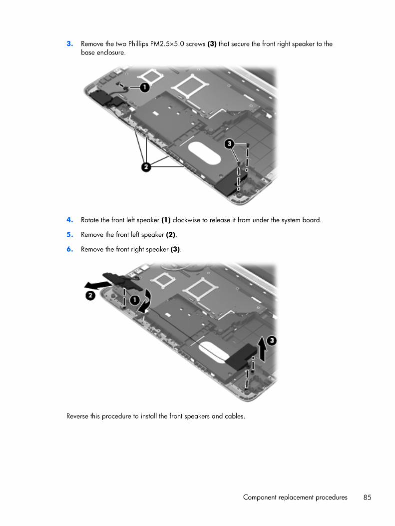
3. Remove the two Phillips PM2.5×5.0 screws (3) that secure the front right speaker to thebase enclosure.
4. Rotate the front left speaker (1) clockwise to release it from under the system board.
5. Remove the front left speaker (2).
6. Remove the front right speaker (3).
Reverse this procedure to install the front speakers and cables.
Component replacement procedures 85
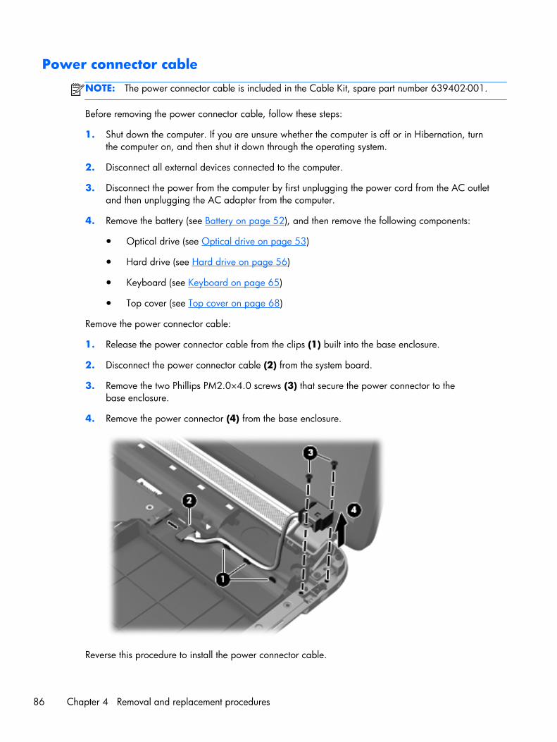
Power connector cable
NOTE: The power connector cable is included in the Cable Kit, spare part number 639402-001.
Before removing the power connector cable, follow these steps:
1. Shut down the computer. If you are unsure whether the computer is off or in Hibernation, turnthe computer on, and then shut it down through the operating system.
2. Disconnect all external devices connected to the computer.
3. Disconnect the power from the computer by first unplugging the power cord from the AC outletand then unplugging the AC adapter from the computer.
4. Remove the battery (see Battery on page 52), and then remove the following components:
● Optical drive (see Optical drive on page 53)
● Hard drive (see Hard drive on page 56)
● Keyboard (see Keyboard on page 65)
● Top cover (see Top cover on page 68)
Remove the power connector cable:
1. Release the power connector cable from the clips (1) built into the base enclosure.
2. Disconnect the power connector cable (2) from the system board.
3. Remove the two Phillips PM2.0×4.0 screws (3) that secure the power connector to thebase enclosure.
4. Remove the power connector (4) from the base enclosure.
Reverse this procedure to install the power connector cable.
86 Chapter 4 Removal and replacement procedures
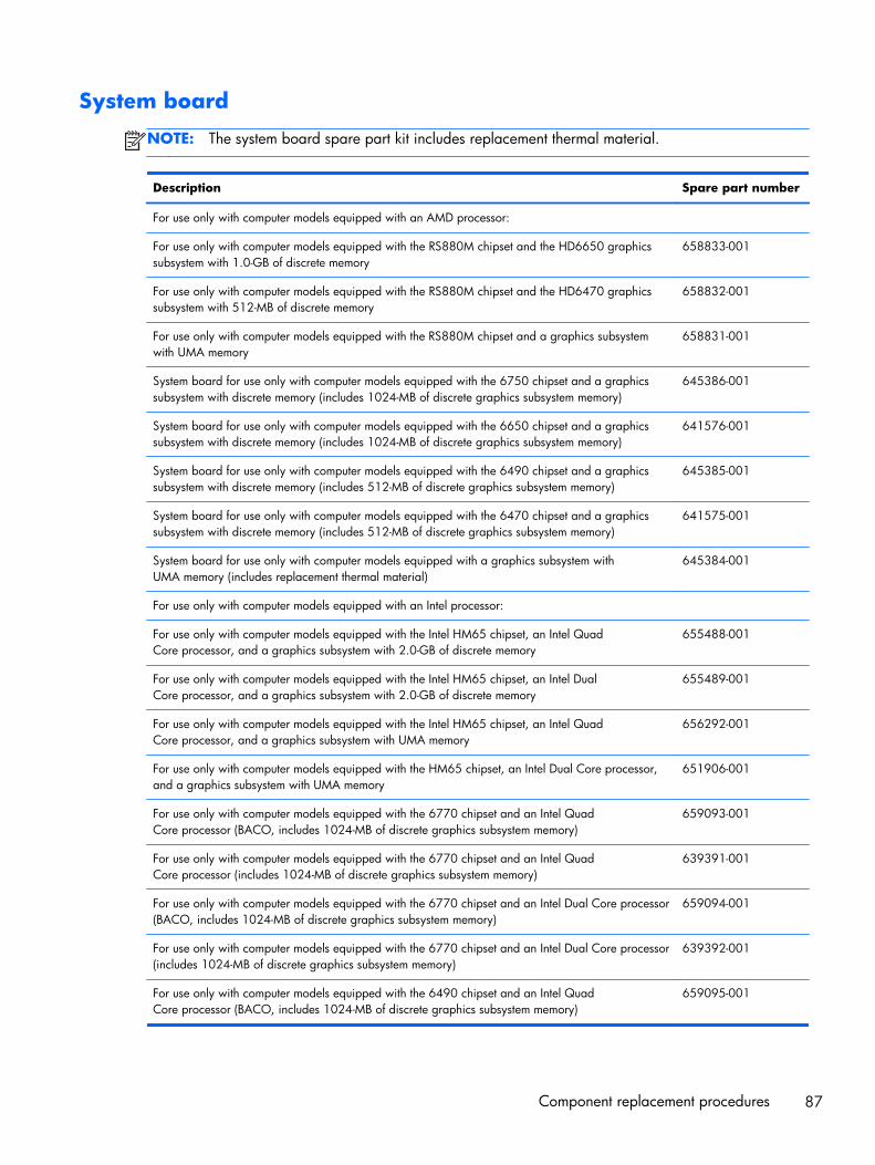
System board
NOTE: The system board spare part kit includes replacement thermal material.
Description Spare part number
For use only with computer models equipped with an AMD processor:
For use only with computer models equipped with the RS880M chipset and the HD6650 graphicssubsystem with 1.0-GB of discrete memory
658833-001
For use only with computer models equipped with the RS880M chipset and the HD6470 graphicssubsystem with 512-MB of discrete memory
658832-001
For use only with computer models equipped with the RS880M chipset and a graphics subsystemwith UMA memory
658831-001
System board for use only with computer models equipped with the 6750 chipset and a graphicssubsystem with discrete memory (includes 1024-MB of discrete graphics subsystem memory)
645386-001
System board for use only with computer models equipped with the 6650 chipset and a graphicssubsystem with discrete memory (includes 1024-MB of discrete graphics subsystem memory)
641576-001
System board for use only with computer models equipped with the 6490 chipset and a graphicssubsystem with discrete memory (includes 512-MB of discrete graphics subsystem memory)
645385-001
System board for use only with computer models equipped with the 6470 chipset and a graphicssubsystem with discrete memory (includes 512-MB of discrete graphics subsystem memory)
641575-001
System board for use only with computer models equipped with a graphics subsystem withUMA memory (includes replacement thermal material)
645384-001
For use only with computer models equipped with an Intel processor:
For use only with computer models equipped with the Intel HM65 chipset, an Intel QuadCore processor, and a graphics subsystem with 2.0-GB of discrete memory
655488-001
For use only with computer models equipped with the Intel HM65 chipset, an Intel DualCore processor, and a graphics subsystem with 2.0-GB of discrete memory
655489-001
For use only with computer models equipped with the Intel HM65 chipset, an Intel QuadCore processor, and a graphics subsystem with UMA memory
656292-001
For use only with computer models equipped with the HM65 chipset, an Intel Dual Core processor,and a graphics subsystem with UMA memory
651906-001
For use only with computer models equipped with the 6770 chipset and an Intel QuadCore processor (BACO, includes 1024-MB of discrete graphics subsystem memory)
659093-001
For use only with computer models equipped with the 6770 chipset and an Intel QuadCore processor (includes 1024-MB of discrete graphics subsystem memory)
639391-001
For use only with computer models equipped with the 6770 chipset and an Intel Dual Core processor(BACO, includes 1024-MB of discrete graphics subsystem memory)
659094-001
For use only with computer models equipped with the 6770 chipset and an Intel Dual Core processor(includes 1024-MB of discrete graphics subsystem memory)
639392-001
For use only with computer models equipped with the 6490 chipset and an Intel QuadCore processor (BACO, includes 1024-MB of discrete graphics subsystem memory)
659095-001
Component replacement procedures 87
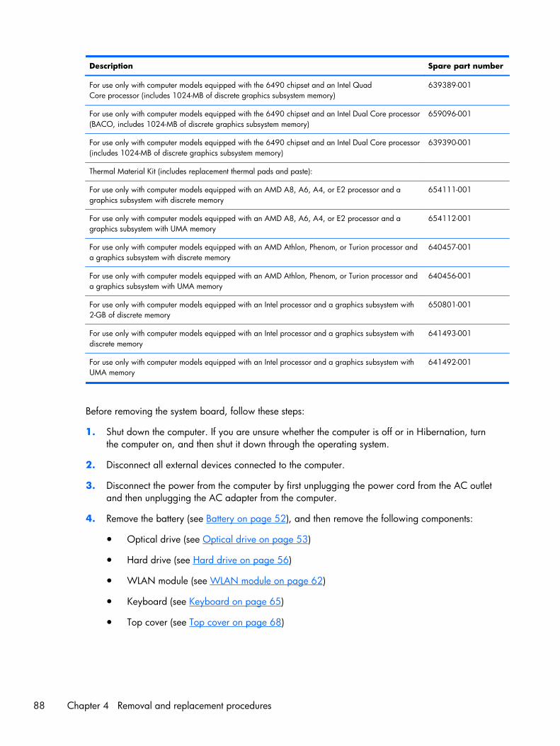
Description Spare part number
For use only with computer models equipped with the 6490 chipset and an Intel QuadCore processor (includes 1024-MB of discrete graphics subsystem memory)
639389-001
For use only with computer models equipped with the 6490 chipset and an Intel Dual Core processor(BACO, includes 1024-MB of discrete graphics subsystem memory)
659096-001
For use only with computer models equipped with the 6490 chipset and an Intel Dual Core processor(includes 1024-MB of discrete graphics subsystem memory)
639390-001
Thermal Material Kit (includes replacement thermal pads and paste):
For use only with computer models equipped with an AMD A8, A6, A4, or E2 processor and agraphics subsystem with discrete memory
654111-001
For use only with computer models equipped with an AMD A8, A6, A4, or E2 processor and agraphics subsystem with UMA memory
654112-001
For use only with computer models equipped with an AMD Athlon, Phenom, or Turion processor anda graphics subsystem with discrete memory
640457-001
For use only with computer models equipped with an AMD Athlon, Phenom, or Turion processor anda graphics subsystem with UMA memory
640456-001
For use only with computer models equipped with an Intel processor and a graphics subsystem with2-GB of discrete memory
650801-001
For use only with computer models equipped with an Intel processor and a graphics subsystem withdiscrete memory
641493-001
For use only with computer models equipped with an Intel processor and a graphics subsystem withUMA memory
641492-001
Before removing the system board, follow these steps:
1. Shut down the computer. If you are unsure whether the computer is off or in Hibernation, turnthe computer on, and then shut it down through the operating system.
2. Disconnect all external devices connected to the computer.
3. Disconnect the power from the computer by first unplugging the power cord from the AC outletand then unplugging the AC adapter from the computer.
4. Remove the battery (see Battery on page 52), and then remove the following components:
● Optical drive (see Optical drive on page 53)
● Hard drive (see Hard drive on page 56)
● WLAN module (see WLAN module on page 62)
● Keyboard (see Keyboard on page 65)
● Top cover (see Top cover on page 68)
88 Chapter 4 Removal and replacement procedures
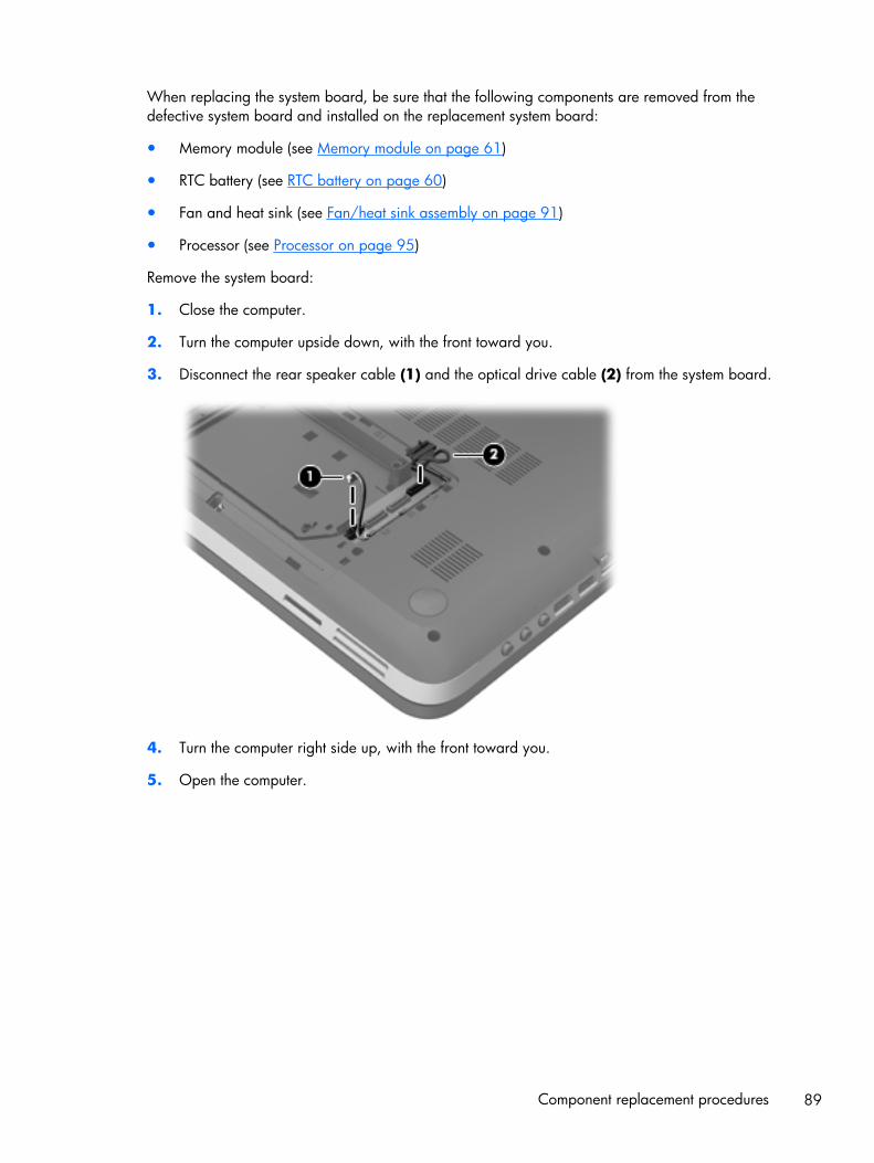
When replacing the system board, be sure that the following components are removed from thedefective system board and installed on the replacement system board:
● Memory module (see Memory module on page 61)
● RTC battery (see RTC battery on page 60)
● Fan and heat sink (see Fan/heat sink assembly on page 91)
● Processor (see Processor on page 95)
Remove the system board:
1. Close the computer.
2. Turn the computer upside down, with the front toward you.
3. Disconnect the rear speaker cable (1) and the optical drive cable (2) from the system board.
4. Turn the computer right side up, with the front toward you.
5. Open the computer.
Component replacement procedures 89
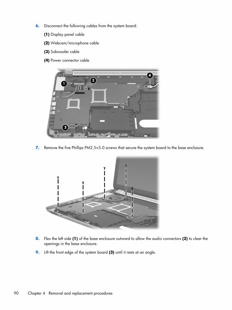
6. Disconnect the following cables from the system board:
(1) Display panel cable
(2) Webcam/microphone cable
(3) Subwoofer cable
(4) Power connector cable
7. Remove the five Phillips PM2.5×5.0 screws that secure the system board to the base enclosure.
8. Flex the left side (1) of the base enclosure outward to allow the audio connectors (2) to clear theopenings in the base enclosure.
9. Lift the front edge of the system board (3) until it rests at an angle.
90 Chapter 4 Removal and replacement procedures
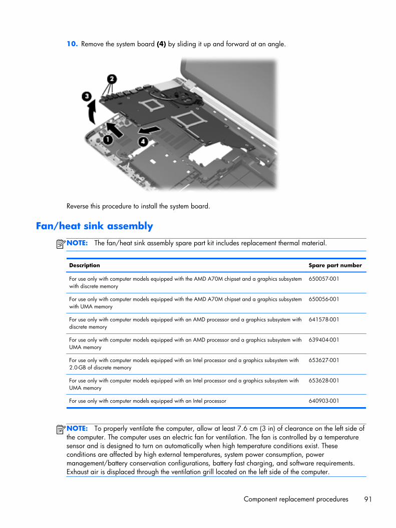
10. Remove the system board (4) by sliding it up and forward at an angle.
Reverse this procedure to install the system board.
Fan/heat sink assembly
NOTE: The fan/heat sink assembly spare part kit includes replacement thermal material.
Description Spare part number
For use only with computer models equipped with the AMD A70M chipset and a graphics subsystemwith discrete memory
650057-001
For use only with computer models equipped with the AMD A70M chipset and a graphics subsystemwith UMA memory
650056-001
For use only with computer models equipped with an AMD processor and a graphics subsystem withdiscrete memory
641578-001
For use only with computer models equipped with an AMD processor and a graphics subsystem withUMA memory
639404-001
For use only with computer models equipped with an Intel processor and a graphics subsystem with2.0-GB of discrete memory
653627-001
For use only with computer models equipped with an Intel processor and a graphics subsystem withUMA memory
653628-001
For use only with computer models equipped with an Intel processor 640903-001
NOTE: To properly ventilate the computer, allow at least 7.6 cm (3 in) of clearance on the left side ofthe computer. The computer uses an electric fan for ventilation. The fan is controlled by a temperaturesensor and is designed to turn on automatically when high temperature conditions exist. Theseconditions are affected by high external temperatures, system power consumption, powermanagement/battery conservation configurations, battery fast charging, and software requirements.Exhaust air is displaced through the ventilation grill located on the left side of the computer.
Component replacement procedures 91
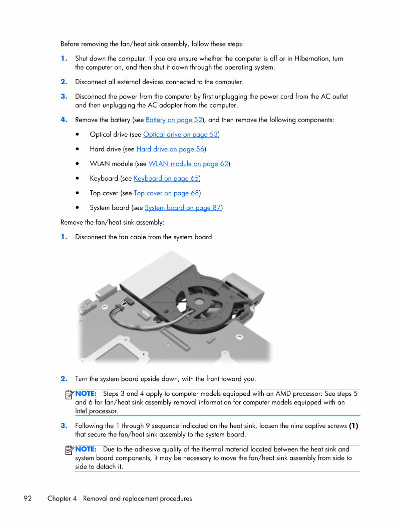
Before removing the fan/heat sink assembly, follow these steps:
1. Shut down the computer. If you are unsure whether the computer is off or in Hibernation, turnthe computer on, and then shut it down through the operating system.
2. Disconnect all external devices connected to the computer.
3. Disconnect the power from the computer by first unplugging the power cord from the AC outletand then unplugging the AC adapter from the computer.
4. Remove the battery (see Battery on page 52), and then remove the following components:
● Optical drive (see Optical drive on page 53)
● Hard drive (see Hard drive on page 56)
● WLAN module (see WLAN module on page 62)
● Keyboard (see Keyboard on page 65)
● Top cover (see Top cover on page 68)
● System board (see System board on page 87)
Remove the fan/heat sink assembly:
1. Disconnect the fan cable from the system board.
2. Turn the system board upside down, with the front toward you.
NOTE: Steps 3 and 4 apply to computer models equipped with an AMD processor. See steps 5and 6 for fan/heat sink assembly removal information for computer models equipped with anIntel processor.
3. Following the 1 through 9 sequence indicated on the heat sink, loosen the nine captive screws (1)that secure the fan/heat sink assembly to the system board.
NOTE: Due to the adhesive quality of the thermal material located between the heat sink andsystem board components, it may be necessary to move the fan/heat sink assembly from side toside to detach it.
92 Chapter 4 Removal and replacement procedures
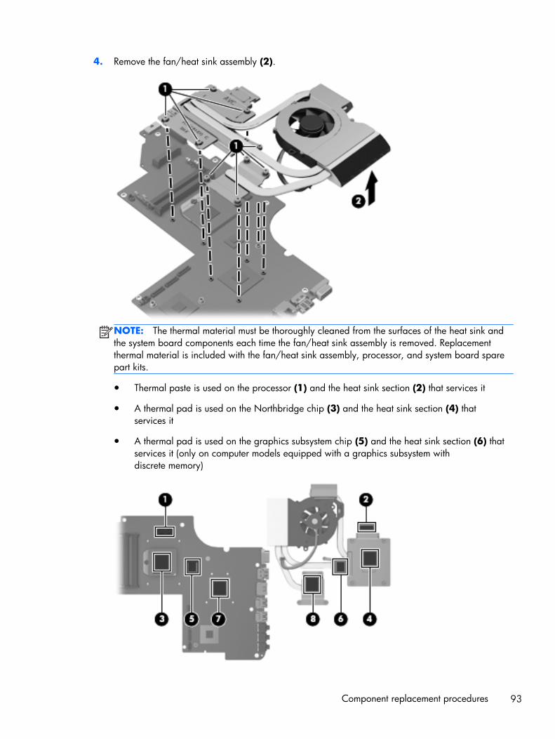
4. Remove the fan/heat sink assembly (2).
NOTE: The thermal material must be thoroughly cleaned from the surfaces of the heat sink andthe system board components each time the fan/heat sink assembly is removed. Replacementthermal material is included with the fan/heat sink assembly, processor, and system board sparepart kits.
● Thermal paste is used on the processor (1) and the heat sink section (2) that services it
● A thermal pad is used on the Northbridge chip (3) and the heat sink section (4) thatservices it
● A thermal pad is used on the graphics subsystem chip (5) and the heat sink section (6) thatservices it (only on computer models equipped with a graphics subsystem withdiscrete memory)
Component replacement procedures 93
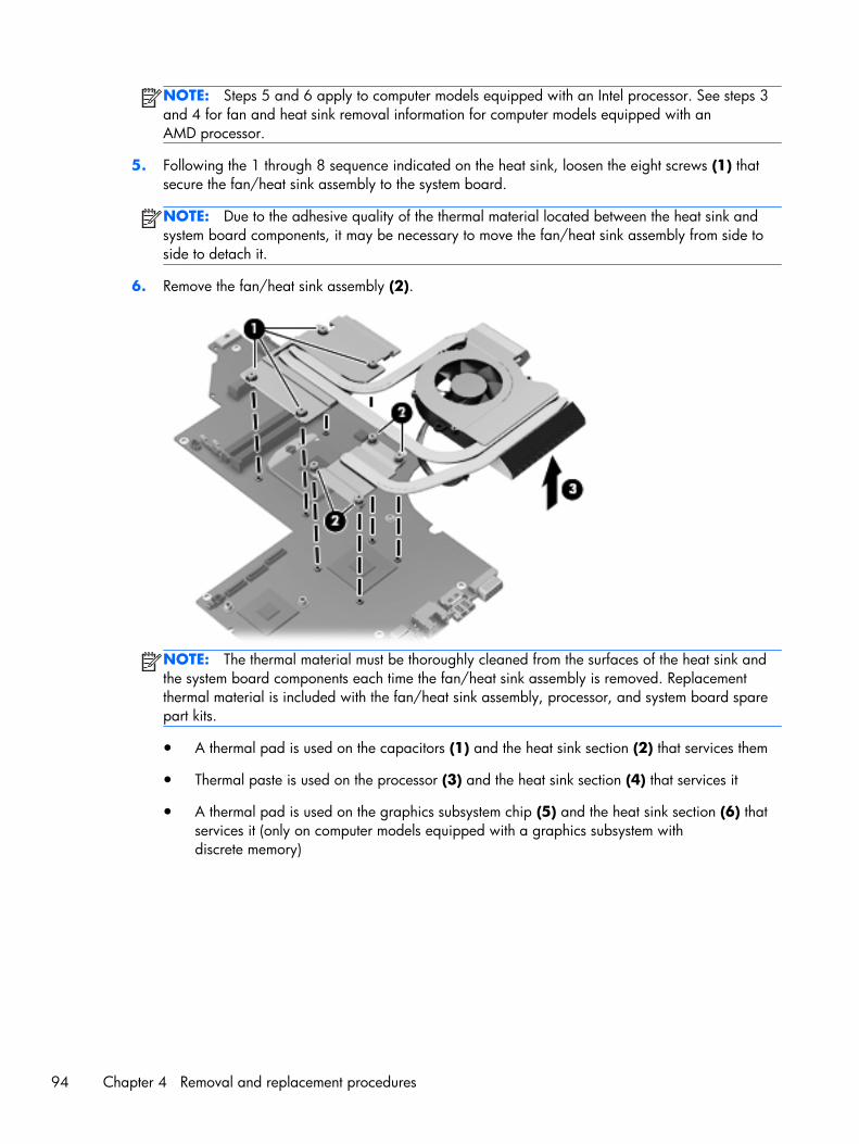
NOTE: Steps 5 and 6 apply to computer models equipped with an Intel processor. See steps 3and 4 for fan and heat sink removal information for computer models equipped with anAMD processor.
5. Following the 1 through 8 sequence indicated on the heat sink, loosen the eight screws (1) thatsecure the fan/heat sink assembly to the system board.
NOTE: Due to the adhesive quality of the thermal material located between the heat sink andsystem board components, it may be necessary to move the fan/heat sink assembly from side toside to detach it.
6. Remove the fan/heat sink assembly (2).
NOTE: The thermal material must be thoroughly cleaned from the surfaces of the heat sink andthe system board components each time the fan/heat sink assembly is removed. Replacementthermal material is included with the fan/heat sink assembly, processor, and system board sparepart kits.
● A thermal pad is used on the capacitors (1) and the heat sink section (2) that services them
● Thermal paste is used on the processor (3) and the heat sink section (4) that services it
● A thermal pad is used on the graphics subsystem chip (5) and the heat sink section (6) thatservices it (only on computer models equipped with a graphics subsystem withdiscrete memory)
94 Chapter 4 Removal and replacement procedures
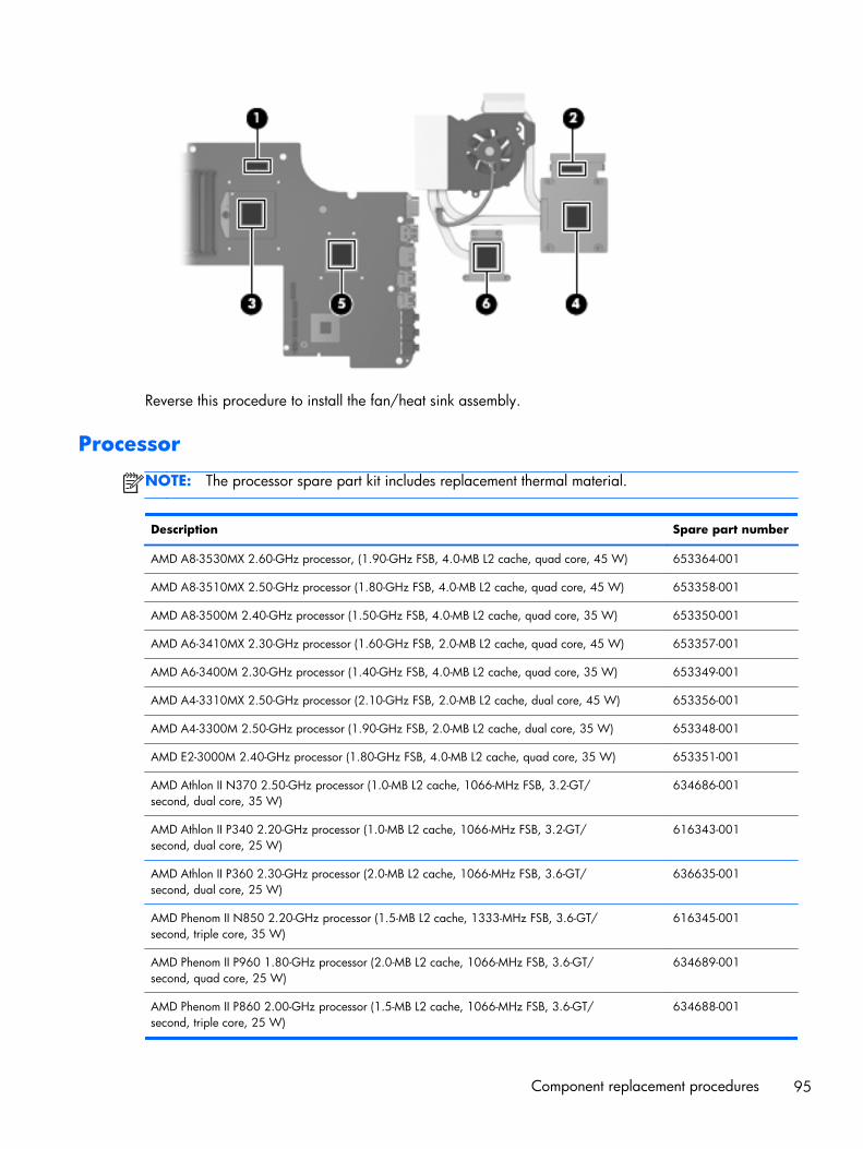
Reverse this procedure to install the fan/heat sink assembly.
Processor
NOTE: The processor spare part kit includes replacement thermal material.
Description Spare part number
AMD A8-3530MX 2.60-GHz processor, (1.90-GHz FSB, 4.0-MB L2 cache, quad core, 45 W) 653364-001
AMD A8-3510MX 2.50-GHz processor (1.80-GHz FSB, 4.0-MB L2 cache, quad core, 45 W) 653358-001
AMD A8-3500M 2.40-GHz processor (1.50-GHz FSB, 4.0-MB L2 cache, quad core, 35 W) 653350-001
AMD A6-3410MX 2.30-GHz processor (1.60-GHz FSB, 2.0-MB L2 cache, quad core, 45 W) 653357-001
AMD A6-3400M 2.30-GHz processor (1.40-GHz FSB, 4.0-MB L2 cache, quad core, 35 W) 653349-001
AMD A4-3310MX 2.50-GHz processor (2.10-GHz FSB, 2.0-MB L2 cache, dual core, 45 W) 653356-001
AMD A4-3300M 2.50-GHz processor (1.90-GHz FSB, 2.0-MB L2 cache, dual core, 35 W) 653348-001
AMD E2-3000M 2.40-GHz processor (1.80-GHz FSB, 4.0-MB L2 cache, quad core, 35 W) 653351-001
AMD Athlon II N370 2.50-GHz processor (1.0-MB L2 cache, 1066-MHz FSB, 3.2-GT/second, dual core, 35 W)
634686-001
AMD Athlon II P340 2.20-GHz processor (1.0-MB L2 cache, 1066-MHz FSB, 3.2-GT/second, dual core, 25 W)
616343-001
AMD Athlon II P360 2.30-GHz processor (2.0-MB L2 cache, 1066-MHz FSB, 3.6-GT/second, dual core, 25 W)
636635-001
AMD Phenom II N850 2.20-GHz processor (1.5-MB L2 cache, 1333-MHz FSB, 3.6-GT/second, triple core, 35 W)
616345-001
AMD Phenom II P960 1.80-GHz processor (2.0-MB L2 cache, 1066-MHz FSB, 3.6-GT/second, quad core, 25 W)
634689-001
AMD Phenom II P860 2.00-GHz processor (1.5-MB L2 cache, 1066-MHz FSB, 3.6-GT/second, triple core, 25 W)
634688-001
Component replacement procedures 95
Description Spare part number
AMD Phenom II P650 2.60-GHz processor (2.0-MB L2 cache, 1333-MHz FSB, 3.6-GT/second, dual core, 25 W)
634687-001
AMD Phenom II N660 3.00-GHz processor (2.0-MB L2 cache, 1333-MHz FSB, 3.6-GT/second,dual core, 35 W)
635494-001
AMD Phenom II N870 2.30-GHz processor (1.5-MB L2 cache, 1333-MHz FSB, 3.6-GT/second, triple core, 35 W)
635495-001
AMD Phenom II N970 2.20-GHz processor (2.0-MB L2 cache, 1333-MHz FSB, 3.6-GT/second, quad core, 35 W)
635496-001
AMD Turion II N570 2.70-GHz processor (2.0-MB L2 cache, 1066-MHz FSB, 3.6-GT/second, dual core, 35 W)
634690-001
AMD Turion II N560 2.50-GHz processor (2.0-MB L2 cache, 1066-MHz FSB, 3.6-GT/second, dual core, 35 W)
634691-001
Intel Quad Core i7-2820QM 2.30-GHz (turbo up to 3.10-GHz) processor (1600-MHz FSB, 8-MBL3 cache, 45 W)
634694-001
Intel Quad Core i7-2720QM 2.20-GHz (turbo up to 3.00-GHz) processor (1600-MHz FSB, 6-MBL3 cache, 45 W)
631254-001
Intel Quad Core i7-2630QM 2.00-GHz (turbo up to 2.90-GHz) processor (1600-MHz FSB, 6-MBL3 cache, 45 W)
635501-001
Intel Dual Core i7-2620M 2.70-GHz (turbo up to 3.40-GHz) processor (1333-MHz FSB, 4-MBL3 cache, 35 W)
631252-001
Intel Dual Core i5-2540M 2.60-GHz (turbo up to 3.30-GHz) processor (1333-MHz FSB, 3-MBL3 cache, 35 W)
631255-001
Intel Dual Core i5-2520M 2.50-GHz (turbo up to 3.20-GHz) processor (1333-MHz FSB, 3-MBL3 cache, 35 W)
631253-001
Intel Dual Core i5-2430M 2.40-GHz (SC turbo up to 3.00-GHz) processor (3.0-MB L3 cache, 35 W) 653341-001
Intel Dual Core i5-2410M 2.30-GHz (turbo up to 2.90-GHz) processor (3-MB L3 cache, 35 W) 638039-001
Intel Dual Core i3-2350M 2.30-GHz processor (3.0-MB L3 cache, 35 W) 653340-001
Intel Dual Core i3-2330M 2.20-GHz processor (3.0-MB L3 cache, 35 W) 653339-001
Intel Dual Core i3-2310M 2.10-GHz processor (3-MB L3 cache, 35 W) 638037-001
Intel Pentium B950 TJ85 2.10-GHz processor (2.0-MB L3 cache, dual core, 35 W) 653338-001
Intel Pentium B940 TJ85 2.00-GHz processor (2.0-MB L3 cache, dual core, 35 W) 653337-001
Before removing the processor, follow these steps:
1. Shut down the computer. If you are unsure whether the computer is off or in Hibernation, turnthe computer on, and then shut it down through the operating system.
2. Disconnect all external devices connected to the computer.
96 Chapter 4 Removal and replacement procedures
3. Disconnect the power from the computer by first unplugging the power cord from the AC outletand then unplugging the AC adapter from the computer.
4. Remove the battery (see Battery on page 52), and then remove the following components:
● Optical drive (see Optical drive on page 53)
● Hard drive (see Hard drive on page 56)
● WLAN module (see WLAN module on page 62)
● Keyboard (see Keyboard on page 65)
● Top cover (see Top cover on page 68)
● System board (see System board on page 87)
● Fan/heat sink assembly (see Fan/heat sink assembly on page 91)
Remove the processor:
1. Use a flat-bladed screw driver (1) to turn the processor locking screw one-half turncounterclockwise (2), until you hear a click.
Component replacement procedures 97
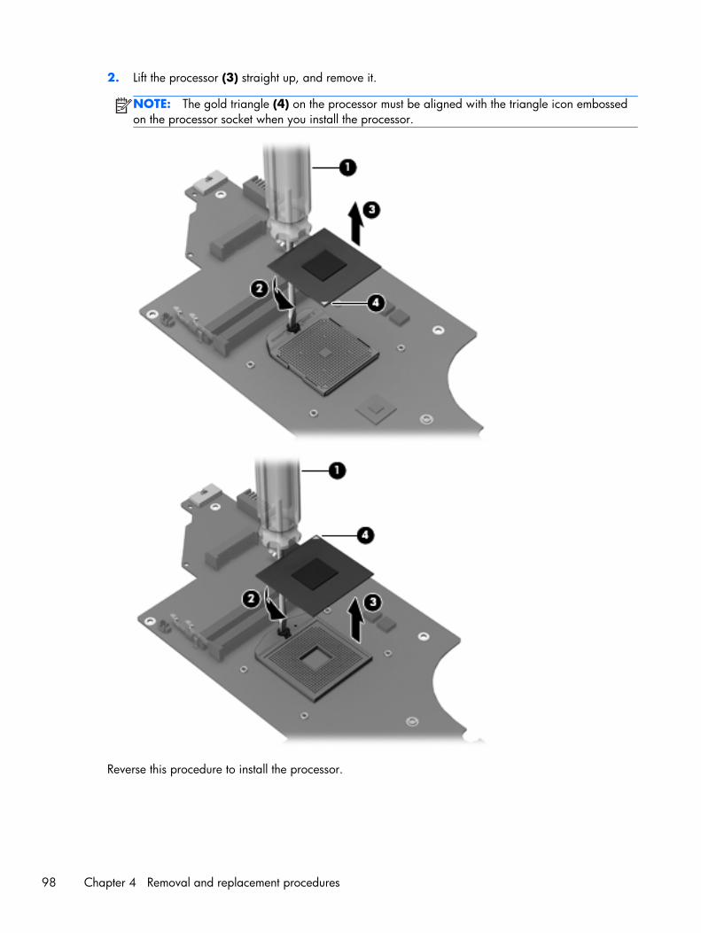
2. Lift the processor (3) straight up, and remove it.
NOTE: The gold triangle (4) on the processor must be aligned with the triangle icon embossedon the processor socket when you install the processor.
Reverse this procedure to install the processor.
98 Chapter 4 Removal and replacement procedures
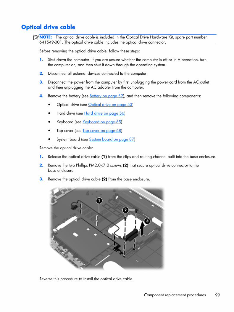
Optical drive cable
NOTE: The optical drive cable is included in the Optical Drive Hardware Kit, spare part number641549-001. The optical drive cable includes the optical drive connector.
Before removing the optical drive cable, follow these steps:
1. Shut down the computer. If you are unsure whether the computer is off or in Hibernation, turnthe computer on, and then shut it down through the operating system.
2. Disconnect all external devices connected to the computer.
3. Disconnect the power from the computer by first unplugging the power cord from the AC outletand then unplugging the AC adapter from the computer.
4. Remove the battery (see Battery on page 52), and then remove the following components:
● Optical drive (see Optical drive on page 53)
● Hard drive (see Hard drive on page 56)
● Keyboard (see Keyboard on page 65)
● Top cover (see Top cover on page 68)
● System board (see System board on page 87)
Remove the optical drive cable:
1. Release the optical drive cable (1) from the clips and routing channel built into the base enclosure.
2. Remove the two Phillips PM2.0×7.0 screws (2) that secure optical drive connector to thebase enclosure.
3. Remove the optical drive cable (2) from the base enclosure.
Reverse this procedure to install the optical drive cable.
Component replacement procedures 99

Rear speakers
Description Spare part number
Rear speakers (include rear left and right speakers, grill, and cable) 641304-001
Before removing the rear speakers, follow these steps:
1. Shut down the computer. If you are unsure whether the computer is off or in Hibernation, turnthe computer on, and then shut it down through the operating system.
2. Disconnect all external devices connected to the computer.
3. Disconnect the power from the computer by first unplugging the power cord from the AC outletand then unplugging the AC adapter from the computer.
4. Remove the battery (see Battery on page 52), and then remove the following components:
● Optical drive (see Optical drive on page 53)
● Hard drive (see Hard drive on page 56)
● WLAN module (see WLAN module on page 62)
● Keyboard (see Keyboard on page 65)
● Top cover (see Top cover on page 68)
● System board (see System board on page 87)
Remove the rear speakers and cables:
1. Close the computer.
2. Turn the computer upside down, with the front toward you.
100 Chapter 4 Removal and replacement procedures
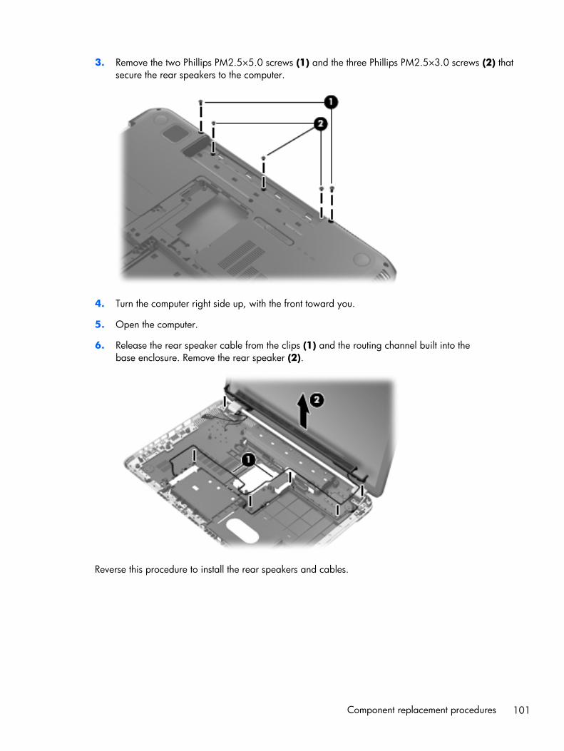
3. Remove the two Phillips PM2.5×5.0 screws (1) and the three Phillips PM2.5×3.0 screws (2) thatsecure the rear speakers to the computer.
4. Turn the computer right side up, with the front toward you.
5. Open the computer.
6. Release the rear speaker cable from the clips (1) and the routing channel built into thebase enclosure. Remove the rear speaker (2).
Reverse this procedure to install the rear speakers and cables.
Component replacement procedures 101
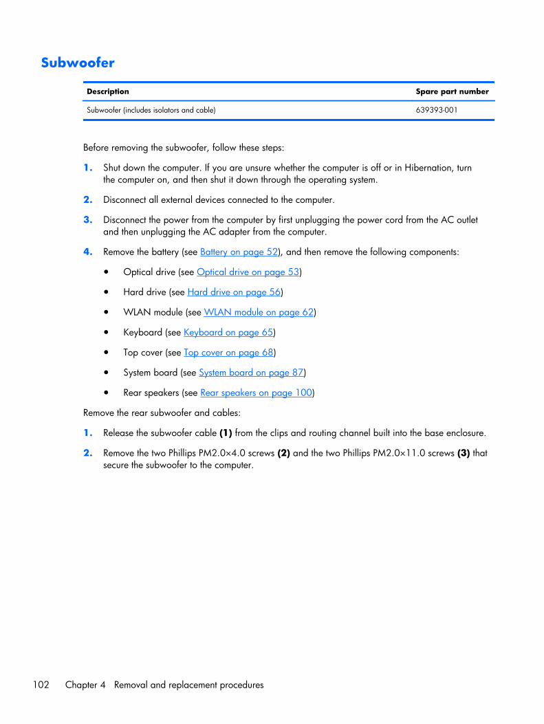
Subwoofer
Description Spare part number
Subwoofer (includes isolators and cable) 639393-001
Before removing the subwoofer, follow these steps:
1. Shut down the computer. If you are unsure whether the computer is off or in Hibernation, turnthe computer on, and then shut it down through the operating system.
2. Disconnect all external devices connected to the computer.
3. Disconnect the power from the computer by first unplugging the power cord from the AC outletand then unplugging the AC adapter from the computer.
4. Remove the battery (see Battery on page 52), and then remove the following components:
● Optical drive (see Optical drive on page 53)
● Hard drive (see Hard drive on page 56)
● WLAN module (see WLAN module on page 62)
● Keyboard (see Keyboard on page 65)
● Top cover (see Top cover on page 68)
● System board (see System board on page 87)
● Rear speakers (see Rear speakers on page 100)
Remove the rear subwoofer and cables:
1. Release the subwoofer cable (1) from the clips and routing channel built into the base enclosure.
2. Remove the two Phillips PM2.0×4.0 screws (2) and the two Phillips PM2.0×11.0 screws (3) thatsecure the subwoofer to the computer.
102 Chapter 4 Removal and replacement procedures
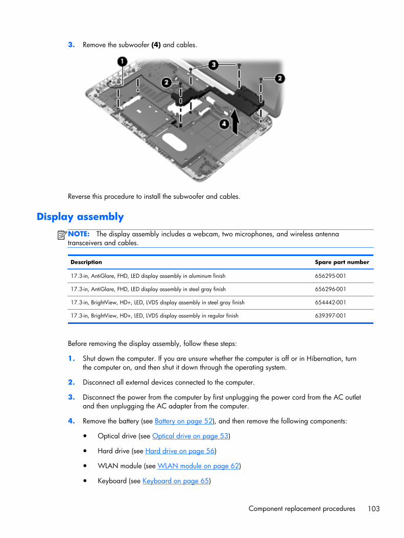
3. Remove the subwoofer (4) and cables.
Reverse this procedure to install the subwoofer and cables.
Display assembly
NOTE: The display assembly includes a webcam, two microphones, and wireless antennatransceivers and cables.
Description Spare part number
17.3-in, AntiGlare, FHD, LED display assembly in aluminum finish 656295-001
17.3-in, AntiGlare, FHD, LED display assembly in steel gray finish 656296-001
17.3-in, BrightView, HD+, LED, LVDS display assembly in steel gray finish 654442-001
17.3-in, BrightView, HD+, LED, LVDS display assembly in regular finish 639397-001
Before removing the display assembly, follow these steps:
1. Shut down the computer. If you are unsure whether the computer is off or in Hibernation, turnthe computer on, and then shut it down through the operating system.
2. Disconnect all external devices connected to the computer.
3. Disconnect the power from the computer by first unplugging the power cord from the AC outletand then unplugging the AC adapter from the computer.
4. Remove the battery (see Battery on page 52), and then remove the following components:
● Optical drive (see Optical drive on page 53)
● Hard drive (see Hard drive on page 56)
● WLAN module (see WLAN module on page 62)
● Keyboard (see Keyboard on page 65)
Component replacement procedures 103
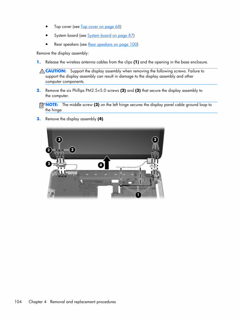
● Top cover (see Top cover on page 68)
● System board (see System board on page 87)
● Rear speakers (see Rear speakers on page 100)
Remove the display assembly:
1. Release the wireless antenna cables from the clips (1) and the opening in the base enclosure.
CAUTION: Support the display assembly when removing the following screws. Failure tosupport the display assembly can result in damage to the display assembly and othercomputer components.
2. Remove the six Phillips PM2.5×5.0 screws (2) and (3) that secure the display assembly tothe computer.
NOTE: The middle screw (3) on the left hinge secures the display panel cable ground loop tothe hinge.
3. Remove the display assembly (4).
104 Chapter 4 Removal and replacement procedures
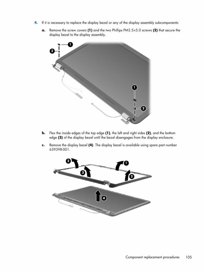
4. If it is necessary to replace the display bezel or any of the display assembly subcomponents:
a. Remove the screw covers (1) and the two Phillips PM2.5×5.0 screws (2) that secure thedisplay bezel to the display assembly.
b. Flex the inside edges of the top edge (1), the left and right sides (2), and the bottomedge (3) of the display bezel until the bezel disengages from the display enclosure.
c. Remove the display bezel (4). The display bezel is available using spare part number639398-001.
Component replacement procedures 105
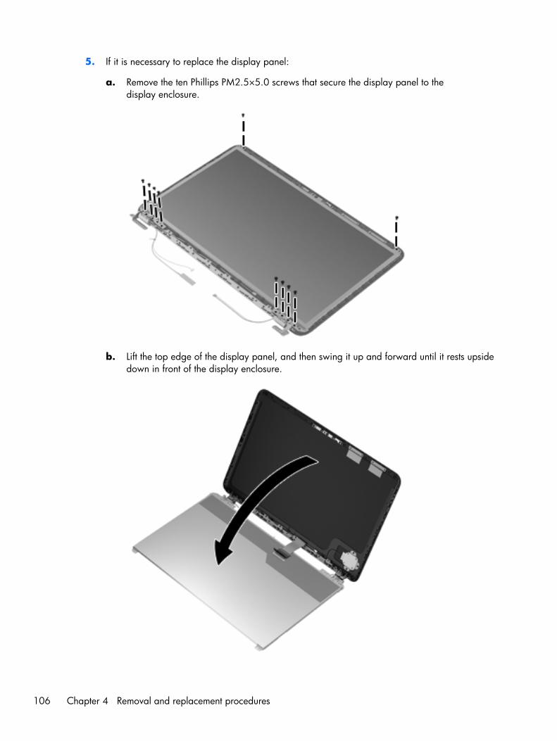
5. If it is necessary to replace the display panel:
a. Remove the ten Phillips PM2.5×5.0 screws that secure the display panel to thedisplay enclosure.
b. Lift the top edge of the display panel, and then swing it up and forward until it rests upsidedown in front of the display enclosure.
106 Chapter 4 Removal and replacement procedures
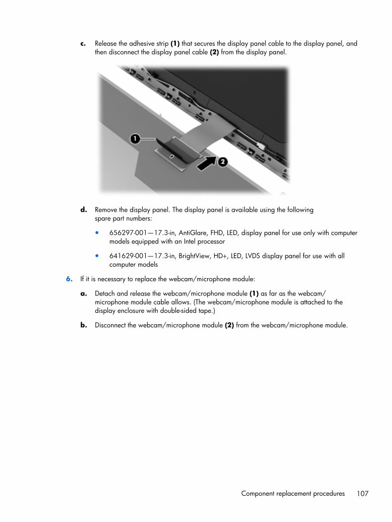
c. Release the adhesive strip (1) that secures the display panel cable to the display panel, andthen disconnect the display panel cable (2) from the display panel.
d. Remove the display panel. The display panel is available using the followingspare part numbers:
● 656297-001—17.3-in, AntiGlare, FHD, LED, display panel for use only with computermodels equipped with an Intel processor
● 641629-001—17.3-in, BrightView, HD+, LED, LVDS display panel for use with allcomputer models
6. If it is necessary to replace the webcam/microphone module:
a. Detach and release the webcam/microphone module (1) as far as the webcam/microphone module cable allows. (The webcam/microphone module is attached to thedisplay enclosure with double-sided tape.)
b. Disconnect the webcam/microphone module (2) from the webcam/microphone module.
Component replacement procedures 107
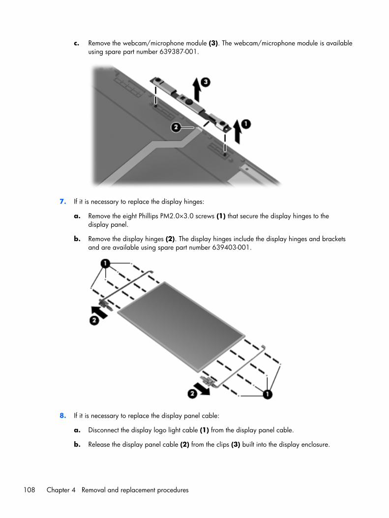
c. Remove the webcam/microphone module (3). The webcam/microphone module is availableusing spare part number 639387-001.
7. If it is necessary to replace the display hinges:
a. Remove the eight Phillips PM2.0×3.0 screws (1) that secure the display hinges to thedisplay panel.
b. Remove the display hinges (2). The display hinges include the display hinges and bracketsand are available using spare part number 639403-001.
8. If it is necessary to replace the display panel cable:
a. Disconnect the display logo light cable (1) from the display panel cable.
b. Release the display panel cable (2) from the clips (3) built into the display enclosure.
108 Chapter 4 Removal and replacement procedures
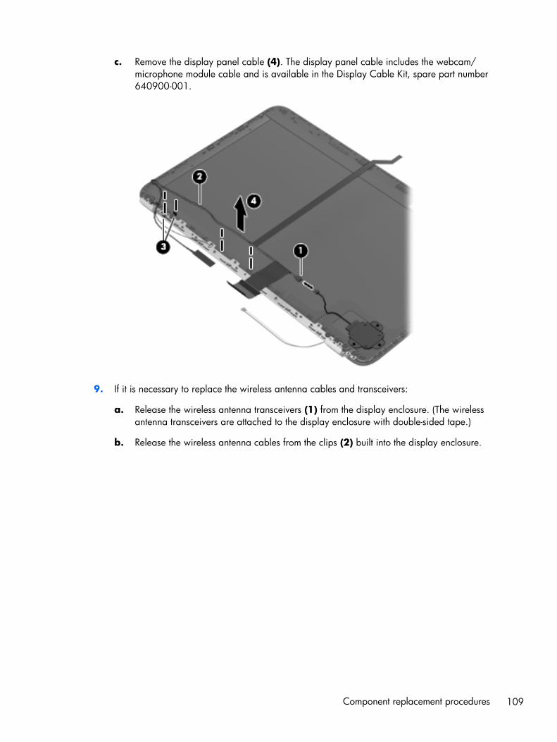
c. Remove the display panel cable (4). The display panel cable includes the webcam/microphone module cable and is available in the Display Cable Kit, spare part number640900-001.
9. If it is necessary to replace the wireless antenna cables and transceivers:
a. Release the wireless antenna transceivers (1) from the display enclosure. (The wirelessantenna transceivers are attached to the display enclosure with double-sided tape.)
b. Release the wireless antenna cables from the clips (2) built into the display enclosure.
Component replacement procedures 109
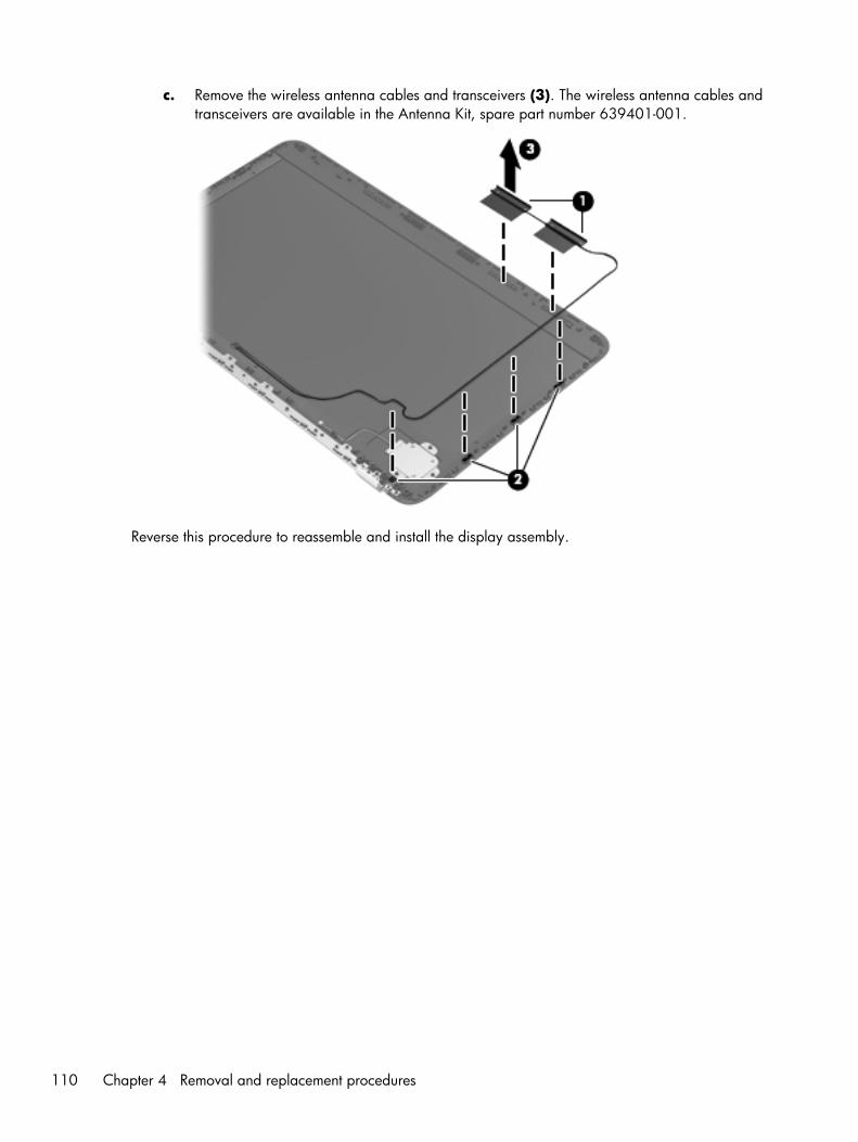
c. Remove the wireless antenna cables and transceivers (3). The wireless antenna cables andtransceivers are available in the Antenna Kit, spare part number 639401-001.
Reverse this procedure to reassemble and install the display assembly.
110 Chapter 4 Removal and replacement procedures
5 Setup Utility (BIOS) and SystemDiagnostics
Using Setup UtilitySetup Utility, or Basic Input/Output System (BIOS), controls communication between all the input andoutput devices on the system (such as disk drives, display, keyboard, mouse, and printer). Setup Utilityincludes settings for the types of peripherals installed, the startup sequence of the computer, and theamount of system and extended memory.
NOTE: Use extreme care when making changes in Setup Utility. Errors can prevent the computer fromoperating properly.
Starting Setup Utility
NOTE: An external keyboard or mouse connected to a USB port can be used with Setup Utility only ifUSB legacy support is enabled.
To start Setup Utility, follow these steps:
1. Turn on or restart the computer, and then press esc while the “Press the ESC key for Startup Menu”message is displayed at the bottom of the screen.
2. Press f10 to enter Setup Utility.
Changing the language of Setup Utility
1. Start Setup Utility.
2. Use the arrow keys to select System Configuration > Language, and then press enter.
3. Use the arrow keys to select a language, and then press enter.
4. When a confirmation prompt with your language selected is displayed, press enter.
5. To save your change and exit Setup Utility, use the arrow keys to select Exit > Exit SavingChanges, and then press enter.
Your change takes effect immediately.
Using Setup Utility 111
Navigating and selecting in Setup Utility
To navigate and select in Setup Utility, follow these steps:
1. Turn on or restart the computer, and then press esc while the “Press the ESC key for Startup Menu”message is displayed at the bottom of the screen.
● To select a menu or a menu item, use the tab key and the keyboard arrow keys and thenpress enter, or use a pointing device to click the item.
● To scroll up and down, click the up arrow or the down arrow in the upper-right corner ofthe screen, or use the up arrow key or the down arrow key.
● To close open dialog boxes and return to the main Setup Utility screen, press esc, and thenfollow the on-screen instructions.
NOTE: You can use either a pointing device (TouchPad, pointing stick, or USB mouse) or thekeyboard to navigate and make selections in Setup Utility.
2. Press f10 to enter Setup Utility.
To exit Setup Utility menus, choose one of the following methods:
● To exit Setup Utility menus without saving your changes, click the Exit icon in the lower-left cornerof the screen, and then follow the on-screen instructions.
– or –
Use the tab key and the arrow keys to select File > Ignore Changes and Exit, and then pressenter.
● To save your changes and exit Setup Utility menus, click the Save icon in the lower-left corner ofthe screen, and then follow the on-screen instructions.
– or –
Use the tab key and the arrow keys to select File > Save Changes and Exit, and then pressenter.
Your changes go into effect when the computer restarts.
Displaying system information
1. Start Setup Utility.
2. Select the Main menu. System information such as the system time and date, and identificationinformation about the computer is displayed.
3. To exit Setup Utility without changing any settings, use the arrow keys to select Exit > ExitDiscarding Changes, and then press enter.
112 Chapter 5 Setup Utility (BIOS) and System Diagnostics
Restoring factory settings in Setup Utility
NOTE: Restoring defaults will not change the hard drive mode.
To return all settings in Setup Utility to the values that were set at the factory, follow these steps:
1. Turn on or restart the computer, and then press esc while the “Press the ESC key for Startup Menu”message is displayed at the bottom of the screen.
2. Press f10 to enter Setup Utility.
3. Use a pointing device or the arrow keys to select File > Restore Defaults.
4. Follow the on-screen instructions.
5. To save your changes and exit, click the Save icon in the lower-left corner of the screen, and thenfollow the on-screen instructions.
– or –
Use the arrow keys to select File > Save Changes and Exit, and then press enter.
Your changes go into effect when the computer restarts.
NOTE: Your password settings and security settings are not changed when you restore the factorysettings.
Exiting Setup Utility
● To exit Setup Utility and save your changes from the current session:
If the Setup Utility menus are not visible, press esc to return to the menu display. Then use thearrow keys to select Exit > Exit Saving Changes, and then press enter.
● To exit Setup Utility without saving your changes from the current session:
If the Setup Utility menus are not visible, press esc to return to the menu display. Then use thearrow keys to select Exit > Exit Discarding Changes, and then press enter.
Updating the BIOS
Updated versions of the BIOS may be available on the HP Web site.
Most BIOS updates on the HP Web site are packaged in compressed files called SoftPaqs.
Some download packages contain a file named Readme.txt, which contains information regardinginstalling and troubleshooting the file.
Using Setup Utility 113
Determining the BIOS version
To determine whether available BIOS updates contain later BIOS versions than those currently installedon the computer, you need to know the version of the system BIOS currently installed.
BIOS version information (also known as ROM date and System BIOS) can be displayed by pressing fn+esc (if you are already in Windows) or by using Setup Utility.
1. Start Setup Utility.
2. Use a pointing device or the arrow keys to select File > System Information.
3. To exit Setup Utility without saving your changes, click the Exit icon in the lower-left corner ofthe screen, and then follow the on-screen instructions.
– or –
Use the tab key and the arrow keys to select File > Ignore Changes and Exit, and then pressenter.
Downloading a BIOS update
CAUTION: To reduce the risk of damage to the computer or an unsuccessful installation, downloadand install a BIOS update only when the computer is connected to reliable external power using the ACadapter. Do not download or install a BIOS update while the computer is running on battery power,docked in an optional docking device, or connected to an optional power source. During thedownload and installation, follow these instructions:
Do not disconnect power from the computer by unplugging the power cord from the AC outlet.
Do not shut down the computer or initiate Sleep or Hibernation.
Do not insert, remove, connect, or disconnect any device, cable, or cord.
1. Windows 7—Select Start > Help and Support > Maintain.
Windows XP—Select Start > Help and Support, and then select the software and driversupdate.
2. Follow the on-screen instructions to identify your computer and access the BIOS update you wantto download.
3. At the download area, follow these steps:
a. Identify the BIOS update that is later than the BIOS version currently installed on yourcomputer. Make a note of the date, name, or other identifier. You may need this informationto locate the update later, after it has been downloaded to your hard drive.
b. Follow the on-screen instructions to download your selection to the hard drive. Make a noteof the path to the location on your hard drive where the BIOS update is downloaded. Youwill need to access this path when you are ready to install the update.
NOTE: If you connect your computer to a network, consult the network administrator beforeinstalling any software updates, especially system BIOS updates.
114 Chapter 5 Setup Utility (BIOS) and System Diagnostics
BIOS installation procedures vary. Follow any instructions that are displayed on the screen after thedownload is complete. If no instructions are displayed, follow these steps:
1. Windows 7—Open Windows Explorer by selecting Start > Computer.
Windows XP—Open Windows Explorer by selecting Start > My Computer.
2. Double-click your hard drive designation. The hard drive designation is typically Local Disk (C:).
3. Using the hard drive path you recorded earlier, open the folder on your hard drive that containsthe update.
4. Double-click the file that has an .exe extension (for example, filename.exe).
The BIOS installation begins.
5. Complete the installation by following the on-screen instructions.
NOTE: After a message on the screen reports a successful installation, you can delete thedownloaded file from your hard drive.
Using System DiagnosticsSystem Diagnostics allows you to run diagnostic tests to determine if the computer hardware isfunctioning properly. The following diagnostic tests are available in System Diagnostics:
● Start-up test—This test analyzes the main computer components that are required to startthe computer.
● Run-in test—This test repeats the start-up test and checks for intermittent problems that the start-uptest does not detect.
● Hard disk test—This test analyzes the physical condition of the hard drive, and then checks alldata in every sector of the hard drive. If the test detects a damaged sector, it attempts to move thedata to a good sector.
● Memory test—This test analyzes the physical condition of the memory modules. If it reports anerror, replace the memory modules immediately.
● Battery test—This test analyzes the condition of the battery. If the battery fails the test, contact HPsupport to report the issue and purchase a replacement battery.
You can also view system information and error logs in the System Diagnostics window.
To start System Diagnostics:
1. Turn on or restart the computer. While the “Press the ESC key for Startup Menu” message isdisplayed in the lower-left corner of the screen, press esc. When the Startup Menu is displayed,press f2.
2. Click the diagnostic test you want to run, and then follow the on-screen instructions.
NOTE: If you need to stop a diagnostics test while it is running, press esc.
Using System Diagnostics 115
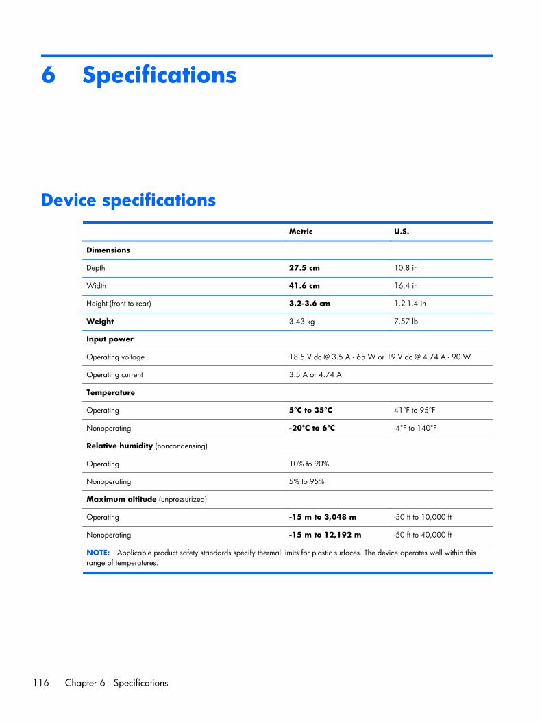
6 Specifications
Device specifications
Metric U.S.
Dimensions
Depth 27.5 cm 10.8 in
Width 41.6 cm 16.4 in
Height (front to rear) 3.2-3.6 cm 1.2-1.4 in
Weight 3.43 kg 7.57 lb
Input power
Operating voltage 18.5 V dc @ 3.5 A - 65 W or 19 V dc @ 4.74 A - 90 W
Operating current 3.5 A or 4.74 A
Temperature
Operating 5°C to 35°C 41°F to 95°F
Nonoperating -20°C to 6°C -4°F to 140°F
Relative humidity (noncondensing)
Operating 10% to 90%
Nonoperating 5% to 95%
Maximum altitude (unpressurized)
Operating -15 m to 3,048 m -50 ft to 10,000 ft
Nonoperating -15 m to 12,192 m -50 ft to 40,000 ft
NOTE: Applicable product safety standards specify thermal limits for plastic surfaces. The device operates well within thisrange of temperatures.
116 Chapter 6 Specifications
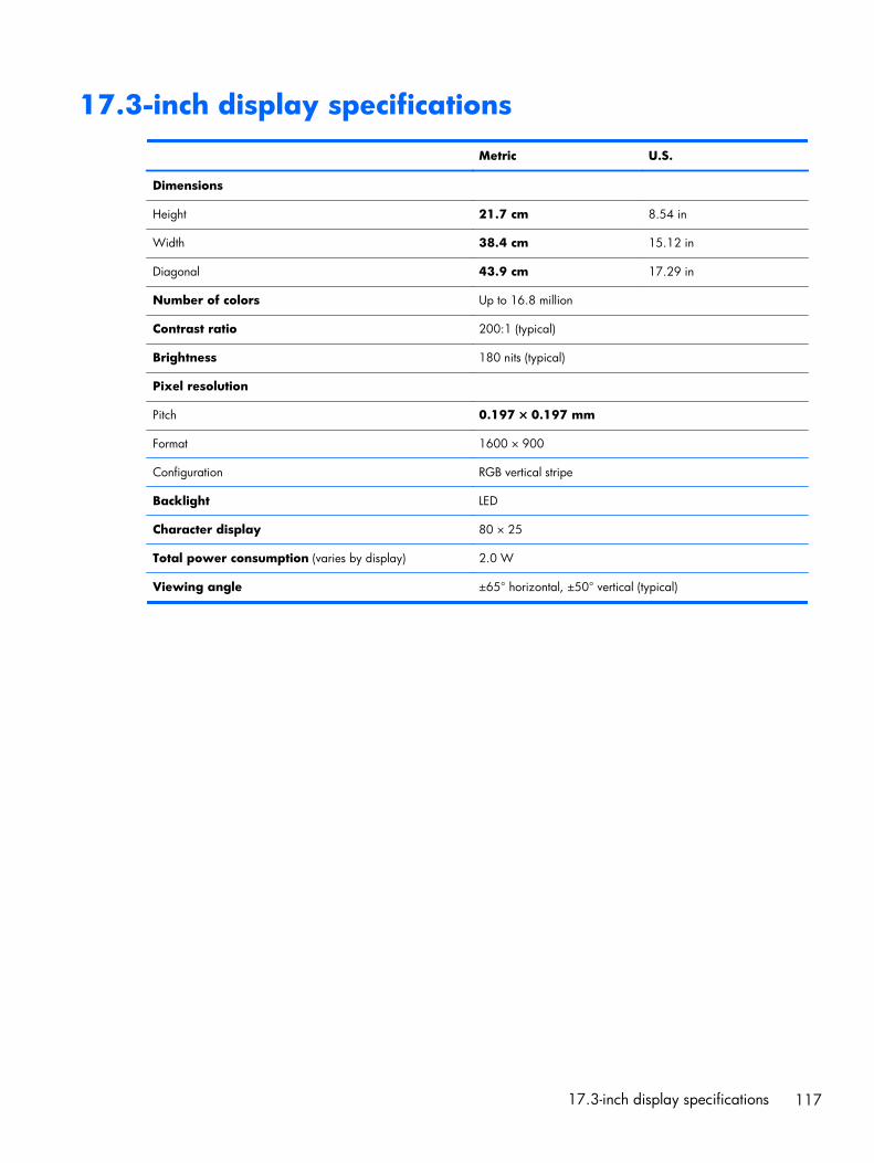
17.3-inch display specifications
Metric U.S.
Dimensions
Height 21.7 cm 8.54 in
Width 38.4 cm 15.12 in
Diagonal 43.9 cm 17.29 in
Number of colors Up to 16.8 million
Contrast ratio 200:1 (typical)
Brightness 180 nits (typical)
Pixel resolution
Pitch 0.197 × 0.197 mm
Format 1600 × 900
Configuration RGB vertical stripe
Backlight LED
Character display 80 × 25
Total power consumption (varies by display) 2.0 W
Viewing angle ±65° horizontal, ±50° vertical (typical)
17.3-inch display specifications 117
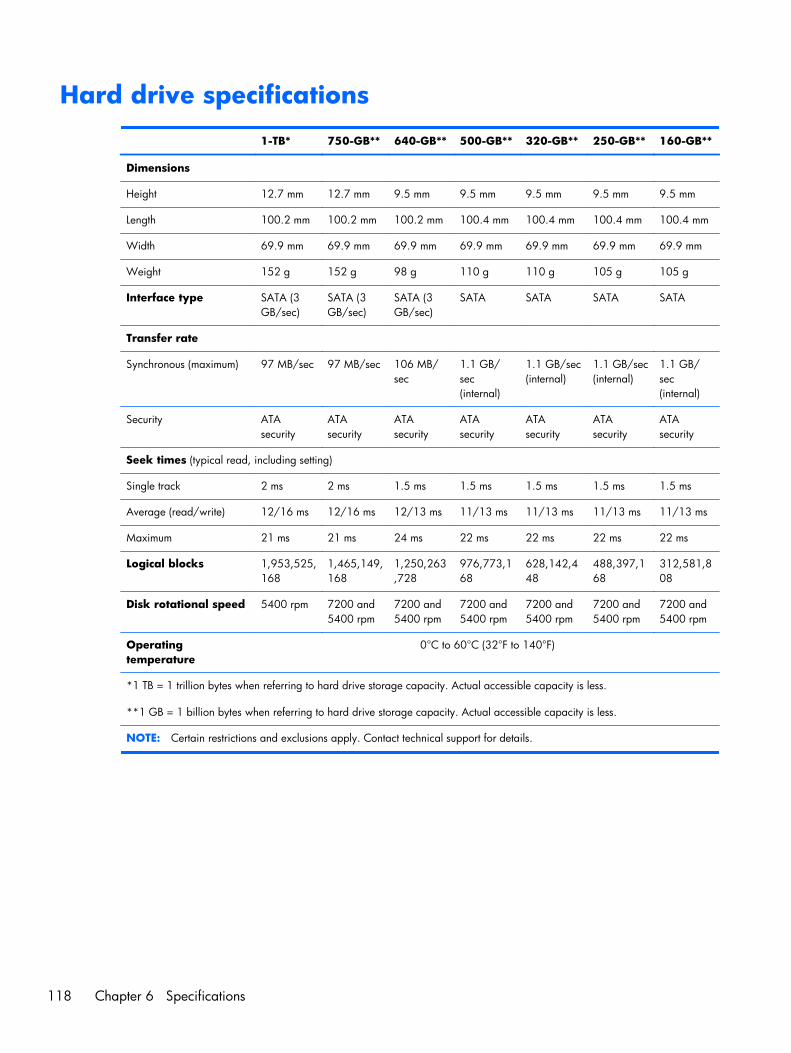
Hard drive specifications
1-TB* 750-GB** 640-GB** 500-GB** 320-GB** 250-GB** 160-GB**
Dimensions
Height 12.7 mm 12.7 mm 9.5 mm 9.5 mm 9.5 mm 9.5 mm 9.5 mm
Length 100.2 mm 100.2 mm 100.2 mm 100.4 mm 100.4 mm 100.4 mm 100.4 mm
Width 69.9 mm 69.9 mm 69.9 mm 69.9 mm 69.9 mm 69.9 mm 69.9 mm
Weight 152 g 152 g 98 g 110 g 110 g 105 g 105 g
Interface type SATA (3GB/sec)
SATA (3GB/sec)
SATA (3GB/sec)
SATA SATA SATA SATA
Transfer rate
Synchronous (maximum) 97 MB/sec 97 MB/sec 106 MB/sec
1.1 GB/sec(internal)
1.1 GB/sec(internal)
1.1 GB/sec(internal)
1.1 GB/sec(internal)
Security ATAsecurity
ATAsecurity
ATAsecurity
ATAsecurity
ATAsecurity
ATAsecurity
ATAsecurity
Seek times (typical read, including setting)
Single track 2 ms 2 ms 1.5 ms 1.5 ms 1.5 ms 1.5 ms 1.5 ms
Average (read/write) 12/16 ms 12/16 ms 12/13 ms 11/13 ms 11/13 ms 11/13 ms 11/13 ms
Maximum 21 ms 21 ms 24 ms 22 ms 22 ms 22 ms 22 ms
Logical blocks 1,953,525,168
1,465,149,168
1,250,263,728
976,773,168
628,142,448
488,397,168
312,581,808
Disk rotational speed 5400 rpm 7200 and5400 rpm
7200 and5400 rpm
7200 and5400 rpm
7200 and5400 rpm
7200 and5400 rpm
7200 and5400 rpm
Operatingtemperature
0°C to 60°C (32°F to 140°F)
*1 TB = 1 trillion bytes when referring to hard drive storage capacity. Actual accessible capacity is less.
**1 GB = 1 billion bytes when referring to hard drive storage capacity. Actual accessible capacity is less.
NOTE: Certain restrictions and exclusions apply. Contact technical support for details.
118 Chapter 6 Specifications
7 Backup and recovery
Your computer includes tools provided by the operating system and HP to help you safeguard yourinformation and restore it if ever needed.
This chapter provides information on the following topics:
● Creating a set of recovery discs or a recovery flash drive (Recovery Manager software feature)
● Performing a system restore (from the partition, recovery discs, or a recovery flash drive)
● Backing up your information
● Recovering a program or driver
RestoreIn the event of hard drive failure, to restore your system to its factory image you will need a set ofrecovery discs or a recovery flash drive that you can create using HP Recovery Manager. HPrecommends that you use this software to create either a set of recovery discs or a recovery flash driveimmediately after software setup.
If for some other reason you need to restore your system, this can be achieved using the HP Recoverypartition (select models only), without the need for recovery discs or a recovery flash drive. To check forthe presence of a recovery partition, click Start, right-click Computer, click Manage, and then clickDisk Management. If the recovery partition is present, a Recovery drive is listed in the window.
CAUTION: HP Recovery Manager (partition, or discs/flash drive) restores only software that waspreinstalled at the factory. Software not provided with this computer must be reinstalled manually.
NOTE: Recovery discs have been included if your computer does not have a recovery partition.
Restore 119
Creating restore mediaHP recommends that you create either a set of recovery discs or a recovery flash drive to be sure thatyou can restore your computer to its original factory state if the hard drive fails, or if for any reason youcannot restore using the recovery partition tools. Create these discs or the flash drive after setting upthe computer for the first time.
NOTE: HP Recovery Manager allows the creation of only one set of recovery discs or one recoveryflash drive. Handle these discs or flash drive carefully and keep them in a safe place.
NOTE: If your computer does not include an integrated optical drive, you can use an optionalexternal optical drive (purchased separately) to create recovery discs, or you can purchase recoverydiscs for your computer from the HP Web site. If you use an external optical drive, it must be connecteddirectly to a USB port on the computer, not to a USB port on an external device, such as a USB hub.
Guidelines:
● Purchase high-quality DVD-R, DVD+R, DVD-R DL, or DVD+R DL discs.
NOTE: Read-write discs, such as CD-RW, DVD±RW, double-layer DVD±RW, and BD-RE(rewritable Blu-ray) discs, are not compatible with the Recovery Manager software.
● The computer must be connected to AC power during this process.
● Only one set of recovery discs or one recovery flash drive can be created per computer.
NOTE: If you are creating recovery discs, number each disc before inserting into the opticaldrive.
● If necessary, you can exit the program before you have finished creating the recovery discs orrecovery flash drive. The next time you open Recovery Manager, you will be prompted to continuethe backup creation process.
To create a set of recovery discs or a recovery flash drive:
1. Select Start > All Programs > Recovery Manager > Recovery Media Creation.
2. Follow the on-screen instructions.
120 Chapter 7 Backup and recovery
Performing a system restoreRecovery Manager software allows you to repair or restore the computer to its original factory state.Recovery Manager works from recovery discs, a recovery flash drive, or from a dedicated recoverypartition (select models only) on the hard drive.
NOTE: A system restore needs to be performed if the computer hard drive has failed or if all attemptsto correct any functional computer issues fail.
A system restore should be used as a final attempt to correct computer issues.
Note the following when performing a system restore:
● You can restore only the system that you have previously backed up. HP recommends that you useHP Recovery Manager to create either a set of recovery discs or a recovery flash drive as soon asyou set up the computer.
● Windows has its own built-in repair features, such as System Restore. If you have not already triedthese features, try them before using Recovery Manager.
● Recovery Manager restores only software that was preinstalled at the factory. Software notprovided with this computer must be downloaded from the manufacturer's Web site or reinstalledfrom the disc provided by the manufacturer.
Restoring using the dedicated recovery partition(select models only)
When using the dedicated recovery partition, there is an option to back up pictures, music and otheraudio, videos and movies, recorded TV shows, documents, spreadsheets and presentations, e-mails,Internet favorites and settings during this process.
To restore the computer from the recovery partition, follow these steps:
1. Access Recovery Manager in either of the following ways:
● Select Start > All Programs > Recovery Manager > Recovery Manager.
– or –
● Turn on or restart the computer, and then press esc while the “Press the ESC key for StartupMenu” message is displayed at the bottom of the screen. Then, press f11 while the “F11(System Recovery)” message is displayed on the screen.
2. Click System Recovery in the Recovery Manager window.
3. Follow the on-screen instructions.
Performing a system restore 121
Restoring using the restore media
1. If possible, back up all personal files.
2. Insert the first recovery disc into the optical drive on your computer or an optional external opticaldrive, and then restart the computer.
– or –
Insert the recovery flash drive into a USB port on your computer, and then restart the computer.
NOTE: If the computer does not automatically restart in the Recovery Manager, the computerboot order needs to be changed.
3. Press f9 at system bootup.
4. Select the optical drive or the flash drive.
5. Follow the on-screen instructions.
Changing the computer boot order
To change the boot order for recovery discs:
1. Restart the computer.
2. Press esc while the computer is restarting, and then press f9 for boot options.
3. Select Internal CD/DVD ROM Drive from the boot options window.
To change the boot order for recovery flash drive:
1. Insert the flash drive into a USB port.
2. Restart the computer.
3. Press esc while the computer is restarting, and then press f9 for boot options.
4. Select the flash drive from the boot options window.
122 Chapter 7 Backup and recovery
Backing up and recovering your informationIt is very important to back up your files and keep any new software in a safe place. As you add newsoftware and data files, continue to create backups on a regular basis.
How completely you are able to recover your system depends on how recent your backup is.
NOTE: A recovery from your most recent backup needs to be performed if the computer has a virusattack or if any major system components fail. In order to correct computer issues, a recovery shouldfirst be attempted before a system restore is attempted. You can back up your information to anoptional external hard drive, a network drive, or discs.
Back up your system at the following times:
● At regularly scheduled times
TIP: Set reminders to back up your information periodically.
● Before the computer is repaired or restored
● Before you add or modify hardware or software
Guidelines:
● Create system restore points using the Windows System Restore feature, and periodically copythem to an optical disc or an external hard drive. For more information on using system restorepoints, refer to Using Windows system restore points.
● Store personal files in the Documents library and back up this folder periodically.
● Save customized settings in a window, toolbar, or menu bar by taking a screen shot of yoursettings. The screen shot can be a time-saver if you have to re-enter your preferences.
To create a screen shot:
1. Display the screen you want to save.
2. Copy the screen image:
To copy only the active window, press alt+fn+prt sc.
To copy the entire screen, press fn+prt sc.
3. Open a word-processing document, and then select Edit > Paste. The screen image is added tothe document.
4. Save and print the document.
Backing up and recovering your information 123
Using Windows Backup and Restore
Guidelines:
● Be sure that the computer is connected to AC power before you start the backup process.
● Allow enough time to complete the backup process. Depending on file sizes, it may take over anhour.
To create a backup:
1. Select Start > Control Panel > System and Security > Backup and Restore.
2. Follow the on-screen instructions to schedule and create a backup.
NOTE: Windows includes the User Account Control feature to improve the security of the computer.You may be prompted for your permission or password for tasks such as installing software, runningutilities, or changing Windows settings. Refer to Help and Support for more information.
Using Windows system restore points
A system restore point allows you to save and name a snapshot of your hard drive at a specific point intime. You can then recover back to that point if you want to reverse subsequent changes.
NOTE: Recovering to an earlier restore point does not affect data files saved or e-mails created sincethe last restore point.
You also can create additional restore points to provide increased protection for your files and settings.
When to create restore points
● Before you add or modify software or hardware
● Periodically, whenever the computer is functioning optimally
NOTE: If you revert to a restore point and then change your mind, you can reverse the restoration.
124 Chapter 7 Backup and recovery
Create a system restore point
1. Select Start > Control Panel > System and Security > System.
2. In the left pane, click System Protection.
3. Click the System Protection tab.
4. Follow the on-screen instructions.
Restore to a previous date and time
To revert to a restore point (created at a previous date and time), when the computer was functioningoptimally, follow these steps:
1. Select Start > Control Panel > System and Security > System.
2. In the left pane, click System Protection.
3. Click the System Protection tab.
4. Click System Restore.
5. Follow the on-screen instructions.
Backing up and recovering your information 125
8 Power cord set requirements
The wide-range input feature of the computer permits it to operate from any line voltage from 100 to120 volts AC, or from 220 to 240 volts AC
The 3-conductor power cord set included with the computer meets the requirements for use in thecountry or region where the equipment is purchased.
Power cord sets for use in other countries and regions must meet the requirements of the country orregion where the computer is used.
Requirements for all countriesThe following requirements are applicable to all countries and regions:
● The length of the power cord set must be at least 1.5 m (5.0 ft) and no more than 2.0 m (6.5 ft).
● All power cord sets must be approved by an acceptable accredited agency responsible forevaluation in the country or region where the power cord set will be used.
● The power cord sets must have a minimum current capacity of 10 amps and a nominal voltagerating of 125 or 250 V AC, as required by the power system of each country or region.
● The appliance coupler must meet the mechanical configuration of an EN 60 320/IEC 320Standard Sheet C13 connector for mating with the appliance inlet on the back of the computer.
126 Chapter 8 Power cord set requirements
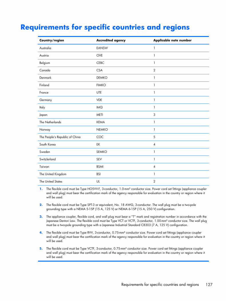
Requirements for specific countries and regions
Country/region Accredited agency Applicable note number
Australia EANSW 1
Austria OVE 1
Belgium CEBC 1
Canada CSA 2
Denmark DEMKO 1
Finland FIMKO 1
France UTE 1
Germany VDE 1
Italy IMQ 1
Japan METI 3
The Netherlands KEMA 1
Norway NEMKO 1
The People's Republic of China COC 5
South Korea EK 4
Sweden SEMKO 1
Switzlerland SEV 1
Taiwan BSMI 4
The United Kingdom BSI 1
The United States UL 2
1. The flexible cord must be Type HO5VV-F, 3-conductor, 1.0-mm² conductor size. Power cord set fittings (appliance couplerand wall plug) must bear the certification mark of the agency responsible for evaluation in the country or region where itwill be used.
2. The flexible cord must be Type SPT-3 or equivalent, No. 18 AWG, 3-conductor. The wall plug must be a two-polegrounding type with a NEMA 5-15P (15 A, 125 V) or NEMA 6-15P (15 A, 250 V) configuration.
3. The appliance coupler, flexible cord, and wall plug must bear a “T” mark and registration number in accordance with theJapanese Dentori Law. The flexible cord must be Type VCT or VCTF, 3-conductor, 1.00-mm² conductor size. The wall plugmust be a two-pole grounding type with a Japanese Industrial Standard C8303 (7 A, 125 V) configuration.
4. The flexible cord must be Type RVV, 3-conductor, 0.75-mm² conductor size. Power cord set fittings (appliance couplerand wall plug) must bear the certification mark of the agency responsible for evaluation in the country or region where itwill be used.
5. The flexible cord must be Type VCTF, 3-conductor, 0.75-mm² conductor size. Power cord set fittings (appliance couplerand wall plug) must bear the certification mark of the agency responsible for evaluation in the country or region where itwill be used.
Requirements for specific countries and regions 127
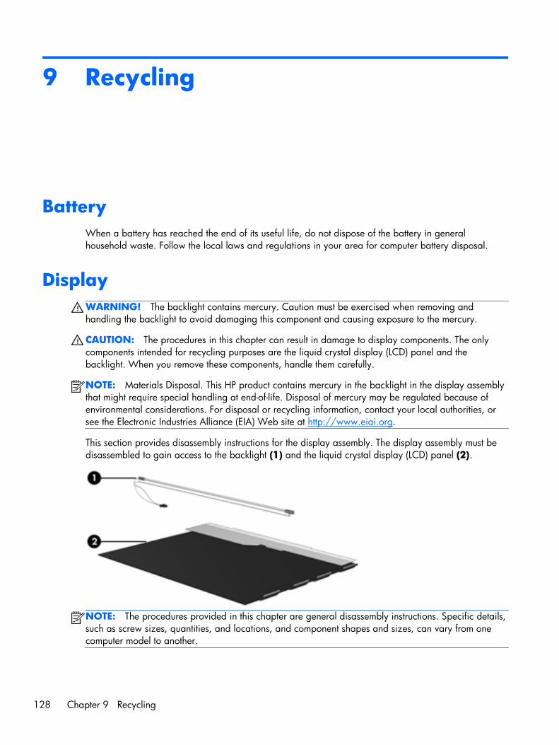
9 Recycling
BatteryWhen a battery has reached the end of its useful life, do not dispose of the battery in generalhousehold waste. Follow the local laws and regulations in your area for computer battery disposal.
DisplayWARNING! The backlight contains mercury. Caution must be exercised when removing andhandling the backlight to avoid damaging this component and causing exposure to the mercury.
CAUTION: The procedures in this chapter can result in damage to display components. The onlycomponents intended for recycling purposes are the liquid crystal display (LCD) panel and thebacklight. When you remove these components, handle them carefully.
NOTE: Materials Disposal. This HP product contains mercury in the backlight in the display assemblythat might require special handling at end-of-life. Disposal of mercury may be regulated because ofenvironmental considerations. For disposal or recycling information, contact your local authorities, orsee the Electronic Industries Alliance (EIA) Web site at http://www.eiai.org.
This section provides disassembly instructions for the display assembly. The display assembly must bedisassembled to gain access to the backlight (1) and the liquid crystal display (LCD) panel (2).
NOTE: The procedures provided in this chapter are general disassembly instructions. Specific details,such as screw sizes, quantities, and locations, and component shapes and sizes, can vary from onecomputer model to another.
128 Chapter 9 Recycling

Perform the following steps:
1. Remove all screw covers (1) and screws (2) that secure the display bezel to the display assembly.
2. Lift up and out on the left and right inside edges (1) and the top and bottom inside edges (2) ofthe display bezel until the bezel disengages from the display assembly.
3. Remove the display bezel (3).
Display 129
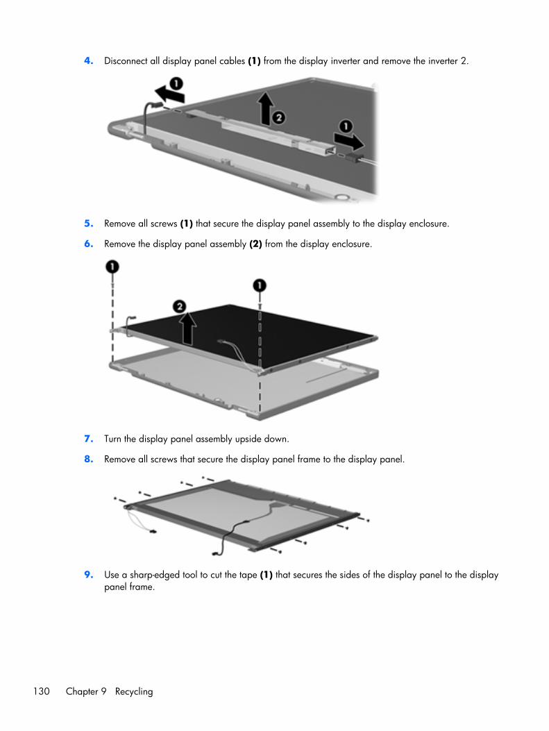
4. Disconnect all display panel cables (1) from the display inverter and remove the inverter 2.
5. Remove all screws (1) that secure the display panel assembly to the display enclosure.
6. Remove the display panel assembly (2) from the display enclosure.
7. Turn the display panel assembly upside down.
8. Remove all screws that secure the display panel frame to the display panel.
9. Use a sharp-edged tool to cut the tape (1) that secures the sides of the display panel to the displaypanel frame.
130 Chapter 9 Recycling
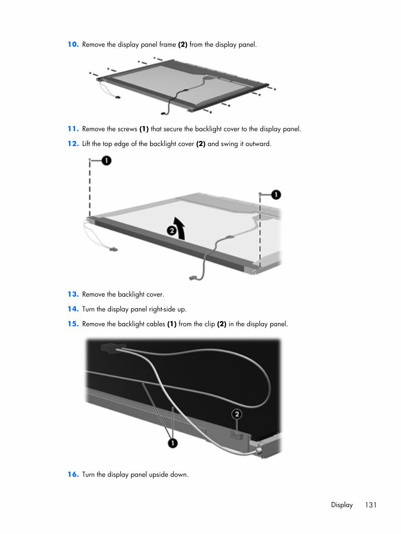
10. Remove the display panel frame (2) from the display panel.
11. Remove the screws (1) that secure the backlight cover to the display panel.
12. Lift the top edge of the backlight cover (2) and swing it outward.
13. Remove the backlight cover.
14. Turn the display panel right-side up.
15. Remove the backlight cables (1) from the clip (2) in the display panel.
16. Turn the display panel upside down.
Display 131
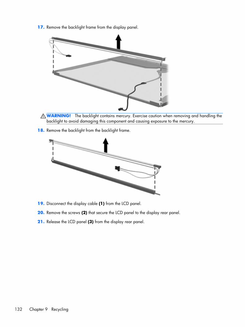
17. Remove the backlight frame from the display panel.
WARNING! The backlight contains mercury. Exercise caution when removing and handling thebacklight to avoid damaging this component and causing exposure to the mercury.
18. Remove the backlight from the backlight frame.
19. Disconnect the display cable (1) from the LCD panel.
20. Remove the screws (2) that secure the LCD panel to the display rear panel.
21. Release the LCD panel (3) from the display rear panel.
132 Chapter 9 Recycling
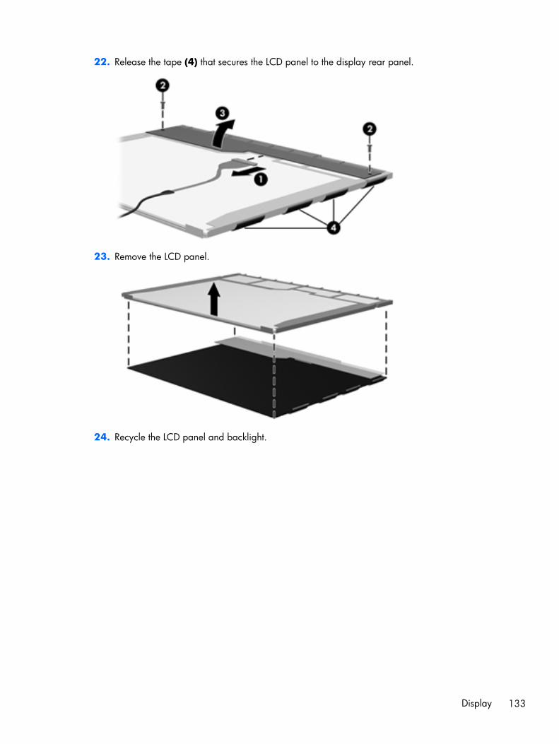
22. Release the tape (4) that secures the LCD panel to the display rear panel.
23. Remove the LCD panel.
24. Recycle the LCD panel and backlight.
Display 133
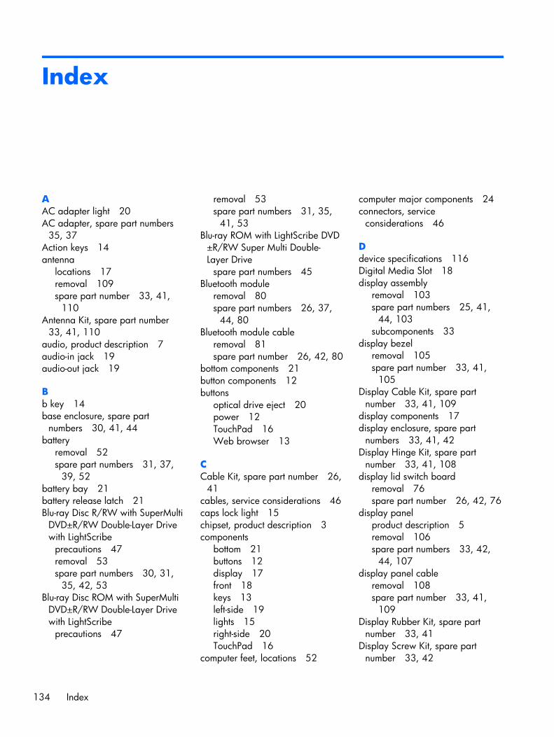
Index
AAC adapter light 20AC adapter, spare part numbers
35, 37Action keys 14antenna
locations 17removal 109spare part number 33, 41,
110Antenna Kit, spare part number
33, 41, 110audio, product description 7audio-in jack 19audio-out jack 19
Bb key 14base enclosure, spare part
numbers 30, 41, 44battery
removal 52spare part numbers 31, 37,
39, 52battery bay 21battery release latch 21Blu-ray Disc R/RW with SuperMulti
DVD±R/RW Double-Layer Drivewith LightScribe
precautions 47removal 53spare part numbers 30, 31,
35, 42, 53Blu-ray Disc ROM with SuperMulti
DVD±R/RW Double-Layer Drivewith LightScribe
precautions 47
removal 53spare part numbers 31, 35,
41, 53Blu-ray ROM with LightScribe DVD
±R/RW Super Multi Double-Layer Drive
spare part numbers 45Bluetooth module
removal 80spare part numbers 26, 37,
44, 80Bluetooth module cable
removal 81spare part number 26, 42, 80
bottom components 21button components 12buttons
optical drive eject 20power 12TouchPad 16Web browser 13
CCable Kit, spare part number 26,
41cables, service considerations 46caps lock light 15chipset, product description 3components
bottom 21buttons 12display 17front 18keys 13left-side 19lights 15right-side 20TouchPad 16
computer feet, locations 52
computer major components 24connectors, service
considerations 46
Ddevice specifications 116Digital Media Slot 18display assembly
removal 103spare part numbers 25, 41,
44, 103subcomponents 33
display bezelremoval 105spare part number 33, 41,
105Display Cable Kit, spare part
number 33, 41, 109display components 17display enclosure, spare part
numbers 33, 41, 42Display Hinge Kit, spare part
number 33, 41, 108display lid switch board
removal 76spare part number 26, 42, 76
display panelproduct description 5removal 106spare part numbers 33, 42,
44, 107display panel cable
removal 108spare part number 33, 41,
109Display Rubber Kit, spare part
number 33, 41Display Screw Kit, spare part
number 33, 42
134 Index
display specifications 117drive light 20drives, preventing damage 47DVD±RW and CD-RW Super Multi
Double-Layer Combo Drive withLightScribe
spare part numbers 45DVD±RW Double-Layer LightScribe
SuperMulti Driveprecautions 47removal 53, 54spare part numbers 31, 35,
41, 53, 54
Eelectrostatic discharge 47equipment guidelines 50esc key 13Ethernet, product description 7external media cards, product
description 8external monitor port 19
Ffan/heat sink assembly
removal 91spare part numbers 29, 41,
42, 43, 91feet, locations 52fingerprint reader board
removal 72spare part number 26, 41, 72
fingerprint reader light 15fingerprint reader, location 13fn key 13front components 18front speakers
removal 84spare part number 26, 40, 84
Ggraphics, product description 4grounding guidelines 47guidelines
equipment 50grounding 47packaging 49transporting 49workstation 49
Hhard drive
precautions 47product description 6removal 56spare part numbers 30, 34,
37, 38, 39, 42, 56specifications 118
hard drive bay 21Hard Drive Hardware Kit, spare
part number 30, 34, 42, 56HDMI port 19headphone jack 19hinge
removal 108spare part number 33, 41,
108
Jjacks
audio-in 19audio-out 19headphone 19microphone 19network 19RJ-45 19
Kkey components 13keyboard
product description 9removal 65spare part numbers 25, 40,
41, 65keys
Action 14b 14esc 13fn 13num lk 14numeric keypad 14Windows applications 14Windows logo 13
Lleft-side components 19light components 15lights
AC adapter 20caps lock 15drive 20
fingerprint reader 15mute 15optical drive 20power 15, 20TouchPad off 15, 16TouchPad on 15, 16webcam 17wireless 15
Mmass storage device
precautions 47removal 53spare part numbers 30, 34,
53memory module
product description 5removal 61spare part numbers 31, 38,
41, 61microphone
locations 17product description 7
microphone jack 19model name 1monitor port 19mute light 15
Nnetwork jack 19num lk key 14numeric keypad 14
Ooperating system, product
description 10optical drive
location 20precautions 47product description 6removal 53spare part numbers 30, 34,
41, 42, 45, 53optical drive bay space saver,
spare part number 31, 35optical drive bezel, illustrated 35optical drive bracket
illustrated 35removal 55
Index 135
optical drive cableillustrated 35removal 99
optical drive eject button 20Optical Drive Hardware Kit, spare
part number 31, 35, 42, 54optical drive light 20
Ppackaging guidelines 49plastic parts, service
considerations 46Plastics Kit, spare part number 42pointing device, product
description 9ports
external monitor 19HDMI 19monitor port 19product description 9SuperSpeed USB 19USB 19, 20
power button 12power button board
removal 74spare part number 26, 41, 74
power connector 20power connector cable, removal
86power cord
requirements for all countries126
requirements for specificcountries and regions 127
set requirements 126spare part numbers 35, 36,
37power light 15, 20power requirements, product
description 9processor
product description 1removal 95spare part numbers 28, 38,
39, 43, 95product description
audio 7chipset 3display panel 5Ethernet 7
external media cards 8graphics 4hard drives 6keyboard 9memory module 5microphone 7operating system 10optical drive 6pointing device 9ports 9power requirements 9processors 1product name 1security 9serviceability 10video 7wireless 7
product name 1
Rrear speakers
removal 100spare part number 30, 42,
100recycling
battery 128display 128
remote control, spare partnumber 36
removal/replacementpreliminaries 46procedures 51
right-side components 20RJ-45 jack 19RTC battery
removal 60spare part number 31, 41, 60
SScrew Kit, spare part number 36,
40SD Card reader board
removal 78spare part number 26, 41, 78
security cable slot 20security, product description 9service considerations
cables 46connectors 46plastic parts 46
service coverremoval 54spare part number 32
service tag 23, 51serviceability, product description
10Setup Utility (BIOS) 111solid-state drive
precautions 47spare part number 30, 34,
41, 56speakers
locations 18removal 84, 100spare part numbers 26, 30,
40, 42, 84, 100specifications
device 116display 117hard drive 118
subwooferlocation 21removal 102spare part number 30, 39,
102SuperSpeed USB port 19system board
removal 87spare part numbers 26, 39,
42, 43, 44, 45, 87System Diagnostics 111
TThermal Material Kit, spare part
numbers 28, 41, 42, 43, 44,88
tools required 46top cover
removal 68spare part numbers 26, 39,
42, 68TouchPad button 16TouchPad components 16TouchPad icon 16TouchPad off light 15, 16TouchPad on light 15, 16TouchPad zone 16transporting guidelines 49
136 Index
UUSB board
removal 82spare part number 26, 42
USB DVB-T dipole antenna, sparepart number 36, 37
USB DVB-T TV tuner, spare partnumber 36, 37
USB port 19, 20
Vvents 19, 21video, product description 7
WWeb browser button 13webcam 17webcam light 17webcam/microphone module
removal 107spare part number 33, 39,
108Windows applications key 14Windows logo key 13wireless antenna
locations 17removal 109spare part number 33, 41,
110wireless light 15wireless, product description 7WLAN module
removal 62spare part numbers 31, 37,
38, 41, 44, 62workstation guidelines 49
Xx
spare part number 45
Index 137