Embed Size (px)
Citation preview
SARUC 2002, Vanderbijlpark, South-Africa
1
MAINTENANCE AND QUALITY RELATED MONITORING OF ROLLING MILL MAIN DRIVES
Dr.-Ing. Jerry Mackel Managing Director, ACIDA-TorqControl GmbH
Kaiserstraß e 100, D-52134 Herzogenrath, Germany Tel: +49 (0) 172 2576967; Fax: +49 (0) 2407 9149.59; eMail: [email protected]
Dipl.-Ing. Martin Fieweger Dept. Torque Sensor Technology and Condition Monitoring, ACIDA-TorqControl GmbH
Kaiserstraß e 100, D-52134 Herzogenrath, Germany Tel: +49 (0) 2407 9149.46; Fax: +49 (0) 2407 9149.59; eMail: mfieweger@acida -torqcontrol.de
Prof. Dr.-Ing. Andreas Asch Dept. of Mech. Engineering, University of Applied Science Iserlohn
Frauenstuhlweg 31, D-58644 Iserlohn, Germany Tel: +49 (0) 2371 566.270; Fax: +49 (0) 2371 566.274; eMail: asch@mfh -iserlohn.de
Introduction
Companies in the industrialised western nations mostly achieve an increase of their productivity by raising the energy input in their production plants, i.e. increasing production speed and rate. The continuous o p-timisation of productivity is especially important in primary industry, for instance the mining and metallurgi-cal industry, as developing countries or those on the threshold of becoming industrialised nations have an advantage due to their potential of human and raw material resources. The increase of the power density within a production process generally implies higher standards in terms of maintenance and process co n-trol, to avoid losses in product quality and machine availability. This requires the extensive use of data a c-quisition, diagnostic engineering and control tools, i.e. condition monitoring.
SARUC 2002, Vanderbijlpark, South-Africa
2
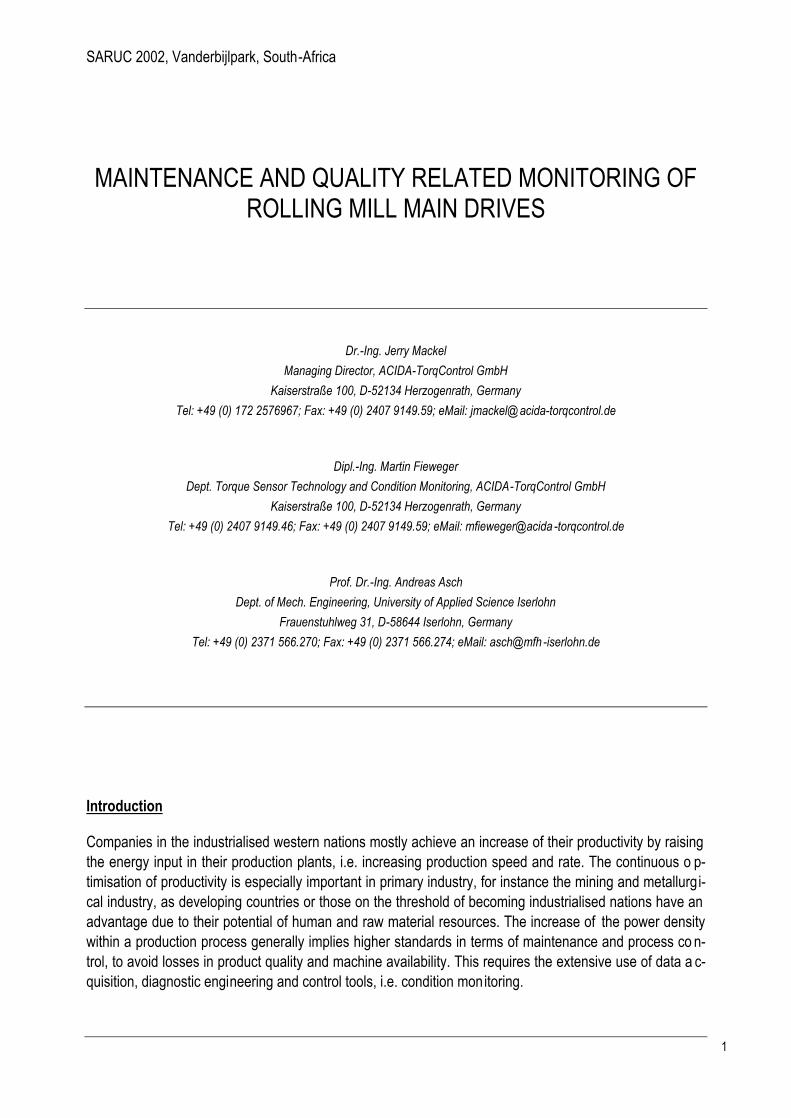
Beneath the rolling force torque is the most important parameter in rolling. Productivity, product quality and plant reliability require a permanent even torque input into the rolling process. In pract ice rolling mill main drives are highly dynamically loaded components: bite impact, reversing rolling practice, torsional vibra-tions, cobbling etc. affect the product and the residual life time of the drive. For the monitoring of rolling mill main drives torque measured directly at the spindles turns out to have outstanding advantages over the current signal from the motor often misused for similar monitoring purposes.
The torque measuring and monitoring system presented in this paper was especially design ed to the needs of heavy machinery drive trains, i.e. rolling mill main drives, and consists of a torque transducer and a computer based monitoring system. The torque transducer was developed for permanent and contin u-ous operation at large shaft diameters with high torque load capacity and rough ambient conditions. The computer based monitoring system features besides general signal analysis functions, rolling mill specific diagnostic functions. Several application examples from practice presented in the pa per will demonstrate the effectiveness and the benefits of the discussed mon itoring strategies and information management.
Figure 1: Motor current versus measured rolling torque at a plate mill
Istmoment_UM_gem Istmoment_UM_ber
-46
103
252
401
550tm
-86.2
-62.9
-39.6
-16.3
7.0
30.3
53.6
76.9
100.2
123.5
146.8
170.1
193.4
216.7
240.0tm
62.84 63.90 64.95 66.00 67.06 68.11 69.16 70.22
s
a
b
SARUC 2002, Vanderbijlpark, South-Africa
3
Torque monitoring system
The aims of torque monitoring systems for rolling mills are:
- to support condition-based maintenance strategies, i.e. the residual life time monitoring of fatigue endangered main drive components
- to control product quality, i.e. to control and avoid torsional chatter - to document and optimise the rolling process (know-how gainings).
A torque monitoring system consists of the torque sensor mounted on the shafts of the main drive of the rolling mill and the computer based monitoring system.
Torque transducers
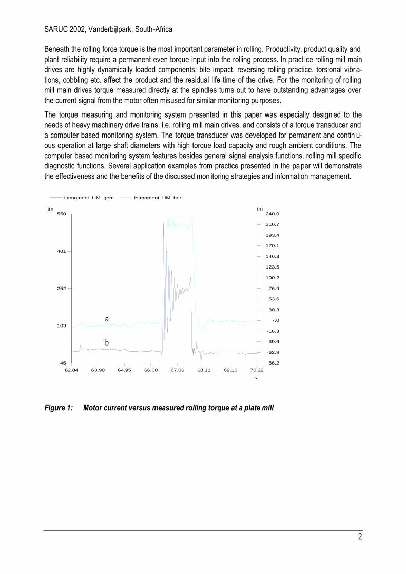
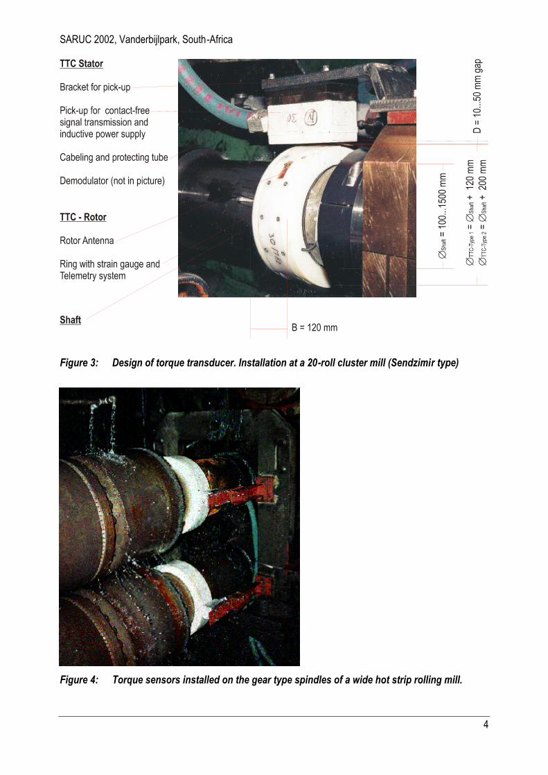
The torque sensors used in rolling mills must be very robust due to the rough ambient conditions. Figure 2 schematically shows a strain gauge and telemetry-based torque measuring system and the signal trans-mission to the computer based monitoring system. In Figure 3 the design of the torque transducer can be seen in detail.
Figure 2: Strain gauge and telemetry-based torque measuring system, designed to withstand the rough ambient in rolling mills.
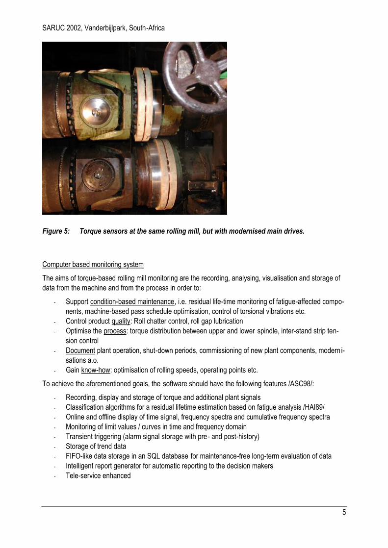
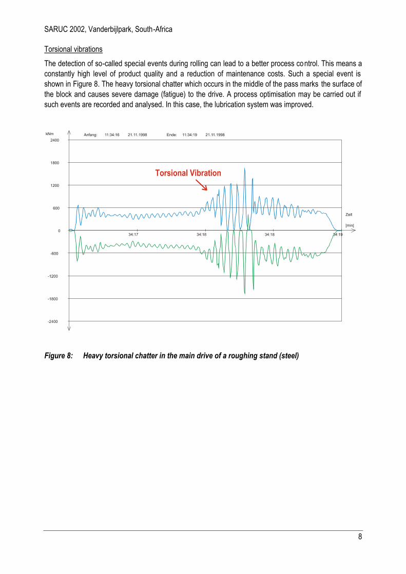
A sophisticated sealing system protects the strain gauge and the electronics on the shaft against water, oil or mechanical damage. Figure 4 shows torque sensors during operation in heavy water spray, installed on an hot strip mill. Figure 5 shows the same rolling mill with modernised main drives, i.e. from gear type to U-joint spindles. Experience has shown that the reliability of torque sensors in rol ling mills can only be guaranteed if the sensor operates fully contact-free, i.e. telemetric signal transmission and inductive power supply.
SARUC 2002, Vanderbijlpark, South-Africa
4
Figure 3: Design of torque transducer. Installation at a 20-roll cluster mill (Sendzimir type)
Figure 4: Torque sensors installed on the gear type spindles of a wide hot strip rolling mill.
SARUC 2002, Vanderbijlpark, South-Africa
5
Figure 5: Torque sensors at the same rolling mill, but with modernised main drives.
Computer based monitoring system
The aims of torque-based rolling mill monitoring are the recording, analysing, visualisation and storage of data from the machine and from the process in order to:
- Support condition-based maintenance, i.e. residual life-time monitoring of fatigue-affected compo-nents, machine-based pass schedule optimisation, control of torsional vibrations etc.
- Control product quality: Roll chatter control, roll gap lubrication - Optimise the process: torque distribution between upper and lower spindle, inter-stand strip ten-
sion control - Document plant operation, shut-down periods, commissioning of new plant components, modern i-
sations a.o. - Gain know-how: optimisation of rolling speeds, operating points etc.
To achieve the aforementioned goals, the software should have the following features /ASC98/:
- Recording, display and storage of torque and additional plant signals - Classification algorithms for a residual lifetime estimation based on fatigue analysis /HAI89/ - Online and offline display of time signal, frequency spectra and cumulative frequency spectra - Monitoring of limit values / curves in time and frequency domain - Transient triggering (alarm signal storage with pre- and post-history) - Storage of trend data - FIFO-like data storage in an SQL database for maintenance-free long-term evaluation of data - Intelligent report generator for automatic reporting to the decision makers - Tele-service enhanced

SARUC 2002, Vanderbijlpark, South-Africa
6
Along with the measured torque, additional plant signals, for example rolling force, mill vibration, block or coil temperature, rolling speed etc. are monitored. Data can be acquired as analogue signals which are connected to A/D data acquisition plug-in boards or alternatively via digital telegrams directly from the PLC and then analysed using automatic monitoring functions and intelligent algorithms. Standardised commu-nication interfaces (i.e. ethernet, TCP/IP) allow the connection to client networks and to the machine co n-trol system or process computer. Monitored signals can thus be stored according to plant and process in-formation, which allows correlation analysis and data trending, i.e. in relation to product ID ’s, material specification etc. This interface can also be used to send measured data or trend values from the torque monitoring system to the process control system.
The visualisation of data and information from monitoring system should be two -fold:
1. Comprehensible and easy-to-read information displayed in the operator stand, which allows a fast feed-back in case of identified trouble, for example ro ll chatter.
2. Fully graphic visualisation of all signals and monitoring results in order to allow engineers to pe r-form in-depth analysis and data mining
Figure 6 shows the design of a torque-based rolling mill monitoring system with additional sensors for online roller bearing diagnosis, temperature and roll chatter monitoring.
Figure 6: Online Machine Monitoring System

SARUC 2002, Vanderbijlpark, South-Africa
7
Examples of practice
The results of some examinations on different types of rolling mills illustrate the installation, use and bene-fits of torque monitoring in rolling mills.
Machine-related pass schedule optimisation
The first example shows a machine-related pass schedule optimisation. This leads to longer lifetime ex-pectations for the high loaded components of the main drive. In the example shown in Figure 7 (reversing roughing mill for aluminium), the original pass schedule foresees 23 passes for a specific material. A l-though this material represents only a small percentage of the annual overall production at this mill stand, the arising torque load damages components of the universal joint at a roughly ten times higher percen t-age in terms of residual lifetime. The optimised pass schedule takes 27 passes and a more even distribu-tion of the torque load. The loss of production time is insignificant, but the lifetime expectation of the spi n-dles increases dramatically. The return-on-investment for the installed torque monitoring system was reached after only a few months.
Figure 7: Machine-related pass schedule optimisation leads to lower torque loads.
SARUC 2002, Vanderbijlpark, South-Africa
8
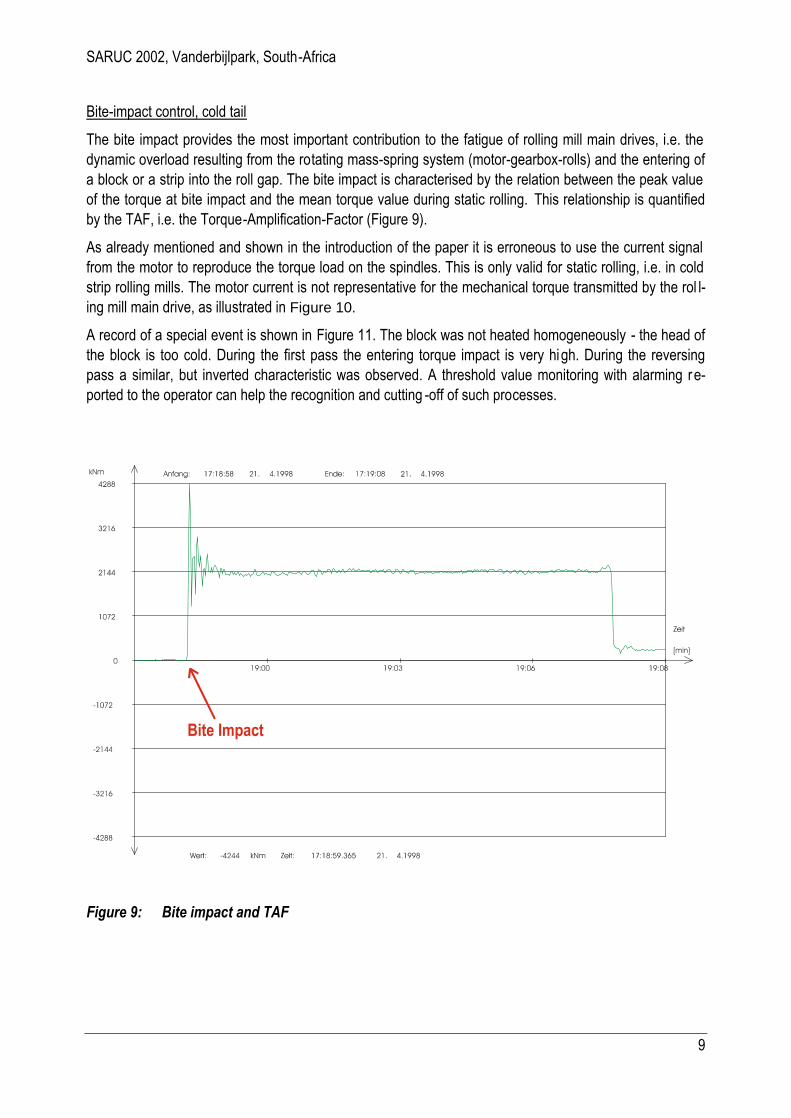
Torsional vibrations
The detection of so-called special events during rolling can lead to a better process control. This means a constantly high level of product quality and a reduction of maintenance costs. Such a special event is shown in Figure 8. The heavy torsional chatter which occurs in the middle of the pass marks the surface of the block and causes severe damage (fatigue) to the drive. A process optimisation may be carried out if such events are recorded and analysed. In this case, the lubrication system was improved.
Figure 8: Heavy torsional chatter in the main drive of a roughing stand (steel)
SARUC 2002, Vanderbijlpark, South-Africa
9
Bite-impact control, cold tail
The bite impact provides the most important contribution to the fatigue of rolling mill main drives, i.e. the dynamic overload resulting from the rotating mass-spring system (motor-gearbox-rolls) and the entering of a block or a strip into the roll gap. The bite impact is characterised by the relation between the peak value of the torque at bite impact and the mean torque value during static rolling. This relationship is quantified by the TAF, i.e. the Torque-Amplification-Factor (Figure 9).
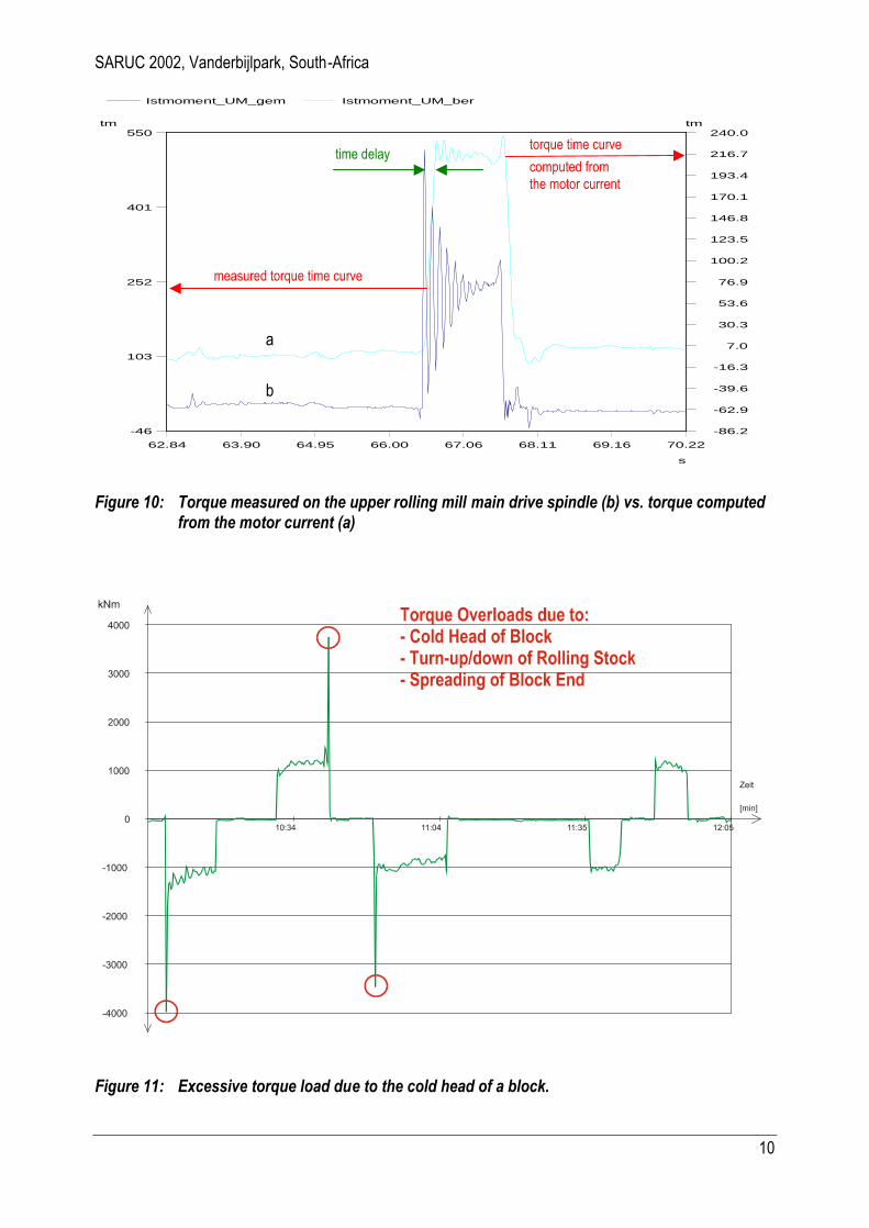
As already mentioned and shown in the introduction of the paper it is erroneous to use the current signal from the motor to reproduce the torque load on the spindles. This is only valid for static rolling, i.e. in cold strip rolling mills. The motor current is not representative for the mechanical torque transmitted by the rol l-ing mill main drive, as illustrated in Figure 10.
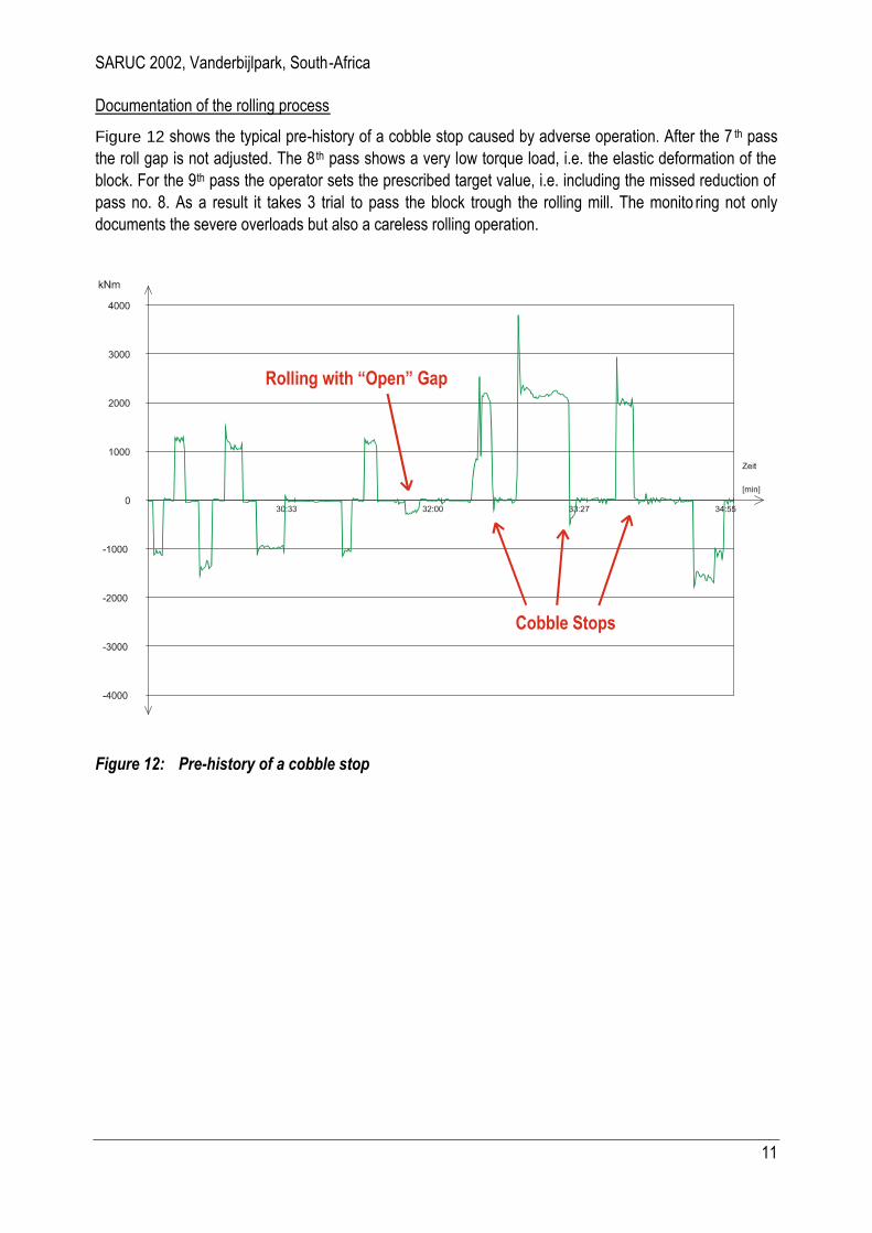
A record of a special event is shown in Figure 11. The block was not heated homogeneously - the head of the block is too cold. During the first pass the entering torque impact is very high. During the reversing pass a similar, but inverted characteristic was observed. A threshold value monitoring with alarming re-ported to the operator can help the recognition and cutting -off of such processes.
Figure 9: Bite impact and TAF
SARUC 2002, Vanderbijlpark, South-Africa
10
Istmoment_UM_gem Istmoment_UM_ber
-46
103
252
401
550tm
-86.2
-62.9
-39.6
-16.3
7.0
30.3
53.6
76.9
100.2
123.5
146.8
170.1
193.4
216.7
240.0tm
62.84 63.90 64.95 66.00 67.06 68.11 69.16 70.22
s
Figure 10: Torque measured on the upper rolling mill main drive spindle (b) vs. torque computed from the motor current (a)
Figure 11: Excessive torque load due to the cold head of a block.
measured torque time curve
torque time curve
computed from the motor current
time delay
a
b
SARUC 2002, Vanderbijlpark, South-Africa
11
Documentation of the rolling process
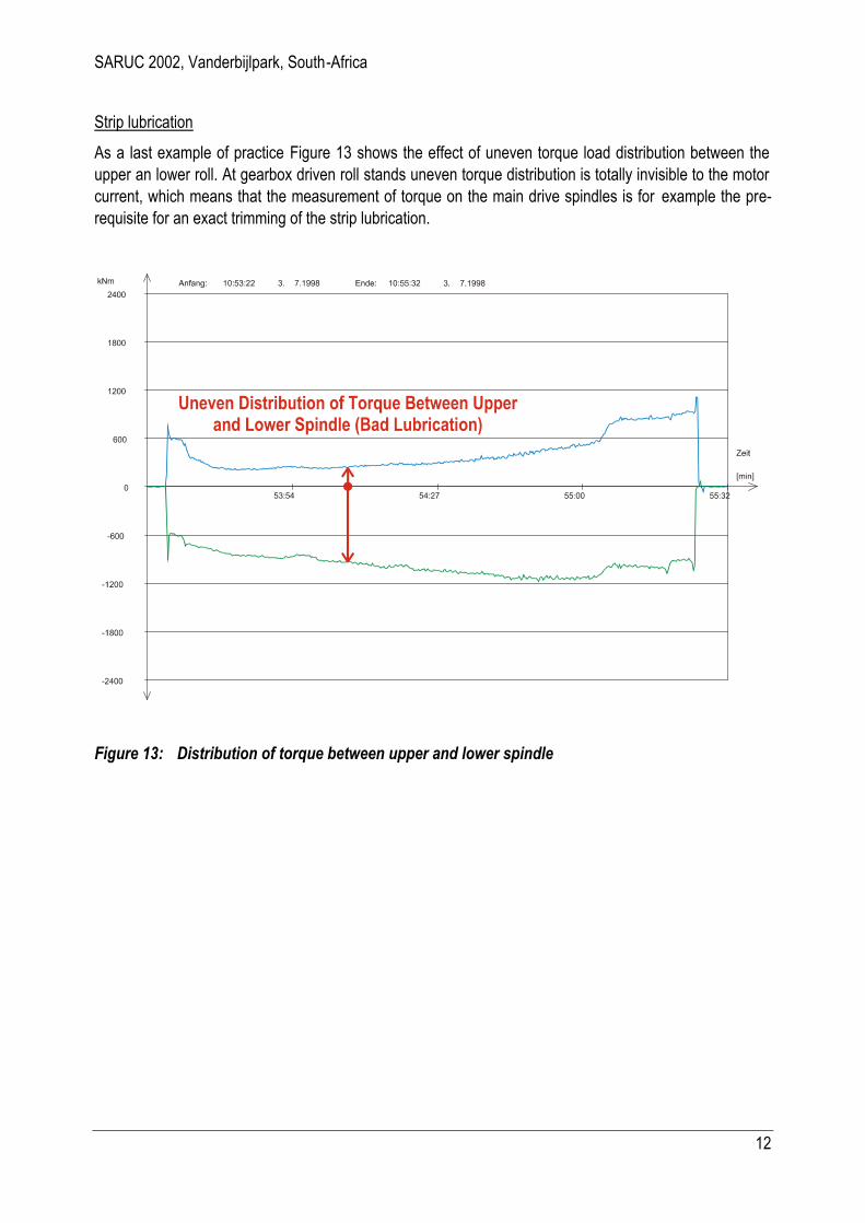
Figure 12 shows the typical pre-history of a cobble stop caused by adverse operation. After the 7 th pass the roll gap is not adjusted. The 8 th pass shows a very low torque load, i.e. the elastic deformation of the block. For the 9th pass the operator sets the prescribed target value, i.e. including the missed reduction of pass no. 8. As a result it takes 3 trial to pass the block trough the rolling mill. The monito ring not only documents the severe overloads but also a careless rolling operation.
Figure 12: Pre-history of a cobble stop
SARUC 2002, Vanderbijlpark, South-Africa
12
Strip lubrication
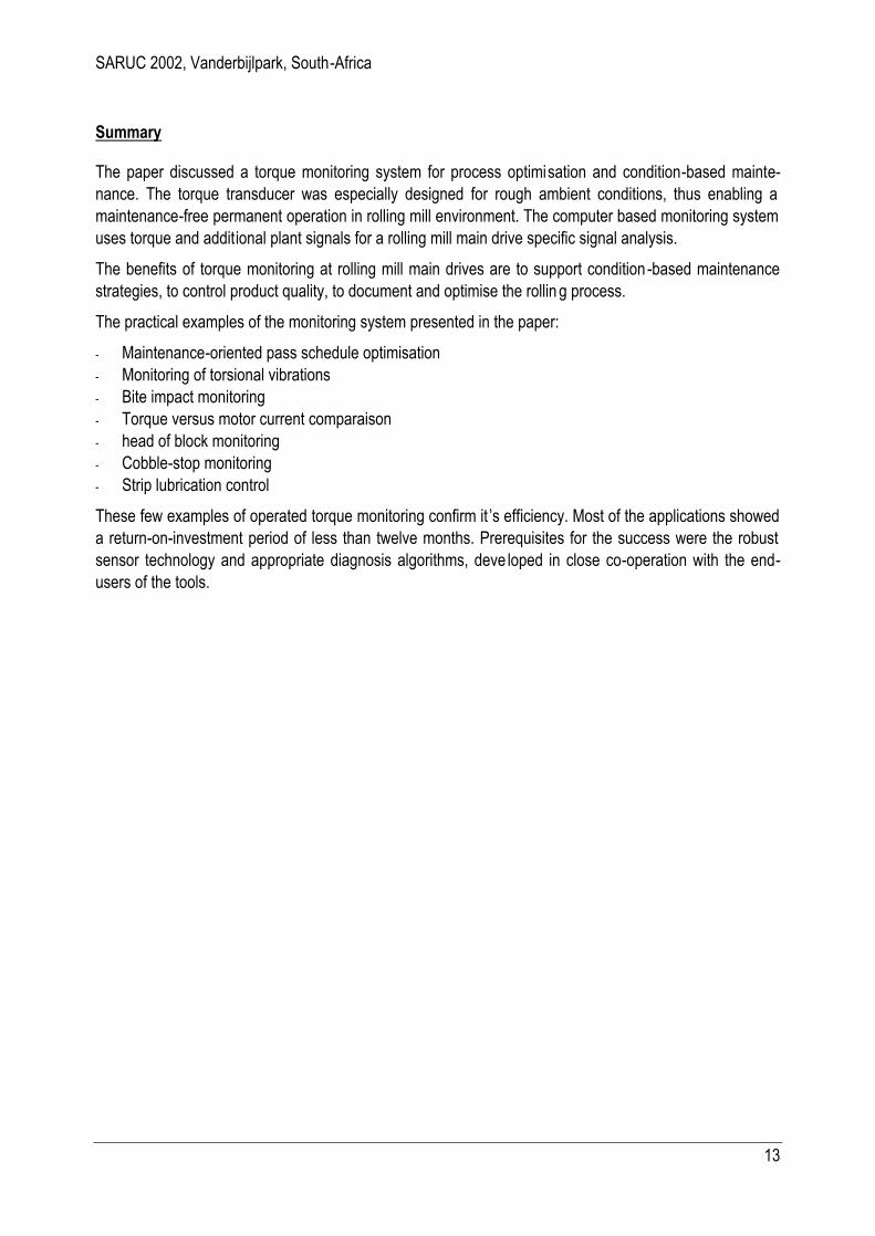
As a last example of practice Figure 13 shows the effect of uneven torque load distribution between the upper an lower roll. At gearbox driven roll stands uneven torque distribution is totally invisible to the motor current, which means that the measurement of torque on the main drive spindles is for example the pre-requisite for an exact trimming of the strip lubrication.
Figure 13: Distribution of torque between upper and lower spindle
SARUC 2002, Vanderbijlpark, South-Africa
13
Summary
The paper discussed a torque monitoring system for process optimisation and condition-based mainte-nance. The torque transducer was especially designed for rough ambient conditions, thus enabling a maintenance-free permanent operation in rolling mill environment. The computer based monitoring system uses torque and additional plant signals for a rolling mill main drive specific signal analysis.
The benefits of torque monitoring at rolling mill main drives are to support condition -based maintenance strategies, to control product quality, to document and optimise the rollin g process.
The practical examples of the monitoring system presented in the paper:
- Maintenance-oriented pass schedule optimisation - Monitoring of torsional vibrations - Bite impact monitoring - Torque versus motor current comparaison - head of block monitoring - Cobble-stop monitoring - Strip lubrication control
These few examples of operated torque monitoring confirm it ’s efficiency. Most of the applications showed a return-on-investment period of less than twelve months. Prerequisites for the success were the robust sensor technology and appropriate diagnosis algorithms, deve loped in close co-operation with the end-users of the tools.
SARUC 2002, Vanderbijlpark, South-Africa
14
References
/ASC01/ Asch, A.; Aigner, C.: The influence of main drive design on economical operation of a wide hot strip mill. In: Proceedings of the SEAISI Singapore Conference (2001)
/ASC98/ Asch, A..; Hohn, W.: Monitoring System for Roll Stand Drives using Strain Gage Technology. In: Proceedings of the 9 th IFAC Symposium on Automation in Mining, Minaral and Metal Proc-essing, S. 175 - 180, IFAC International Federation of Automatic Control (1998).
/HAI89/ Haibach, E.: Betriebsfestigkeit. VDI-Verlag GmbH (1989).
/MAC00/ Mackel, J.: Maintenance and quality related condition monitoring in rolling mills. In: Procee d-ings of the the AISE Annual Convention, Chicago (2000)
/MAC96/ Mackel, J.; Seeliger, A.: Qualitä tssicherung an schnell laufenden Walzanlagen. In: Alma Mater Aquensis RWTH-Aachen (1995/96).
/MAC97/ Mackel, J.; Seeliger, A.; Georges, D.: Measurment and Diagnosis of Process-Disturbing Os-cillations on Plants for Machine Condition Monitoring and Quality Control. In: Proceedings of the XIV Imeko World Congress (1997).
/MAC98/ Mackel, A.; Cerv, H; Keßler, H.-W.; Luckmann, F: Mill Diagnostic System (MiDaS) - a monitoring system with quality- and maintenance-related diagnostic functions. In: Aluminium, Volume 74 (1998).
/SEE95/ Seeliger, A.; Koch, St.; Poschmann, M.: Gekoppelte Schwingungssimulation elektromechan i-scher Antriebe. In: VDI-Berichte Nummer 1220 (1995).