Embed Size (px)
Citation preview
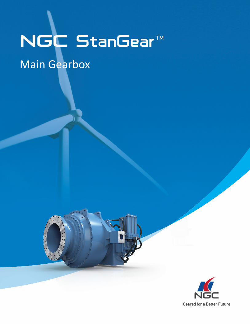
Main Gearbox

Contents1. NGC StanGear Introduction.......................................................................................................... 01
2. General Information...................................................................................................................... 03
2.1 Performance Standards............................................................................................................................................................ 03
2.2 Characteristics............................................................................................................................................................................ 03
2.3 Important Notes......................................................................................................................................................................... 03
2.4 Explanation of Symbols.............................................................................................................................................................. 04
2.5 Scope of Supply........................................................................................................................................................................... 04
3. Summary of Basic Types................................................................................................................ 05
3.1 Nomenclature........................................................................................................................................................................... 05
3.2 Classification of Product............................................................................................................................................................. 06
4. Selection of Gear Units................................................................................................................... 07
4.1 Methods of Selection................................................................................................................................................................. 07
4.2 Selection Examples.................................................................................................................................................................... 08
4.3 Nominal Input Torque & Ratios.................................................................................................................................................. 09
5. Dimensional Drawings................................................................................................................... 11
SMG···1···........................................................................................................................................................................................ 11
SMG···2···......................................................................................................................................................................................... 13
SMG···3···......................................................................................................................................................................................... 15
6. Shrink Disc, SSD............................................................................................................................. 16
Shrink Disc, SSD............................................................................................................................................................................ 16
01
1What is NGC StanGear?
NGC StanGear is a serialized product platform for wind turbine main gearboxes and pitch & yaw drives, developed to provide turbine
manufacturers with the ability to select an appropriate gearbox for their needs from an existing catalog of units. NGC StanGear includes
StanGear standard products and its variants. StanGear standard products refer to those products listed in the NGC platforms, i.e. the
products which have recommended ratios and fulfill the specification in Part 4 and Part 5.
StanGear variants refer to those products adjusted and modified slightly based on the standard products, i.e. based on the specification
in Part 4 and Part 5. (including the adjustment on ratio and interface sizes for torque arm, flange, output shaft, quill shaft and brake disc.)
Please contact NGC for more detailed information.
How was NGC StanGear developed?
Traditionally, wind gearboxes have been designed according to the specifications of wind turbine manufacturers; an approach that has led
to a large diversity of gearboxes within each wind farm, long product development cycles and rigid cost structures due to the limited scale
and reliability risks associated with new designs.
Using data collected from NGC's extensive global installed base of more than 50,000 main gearboxes and more than 300,000 pitch and
yaw drives, the NGC StanGear platform was developed to solve these issues – bringing modularization and standardization to the layout.
NGC StanGear Introduction
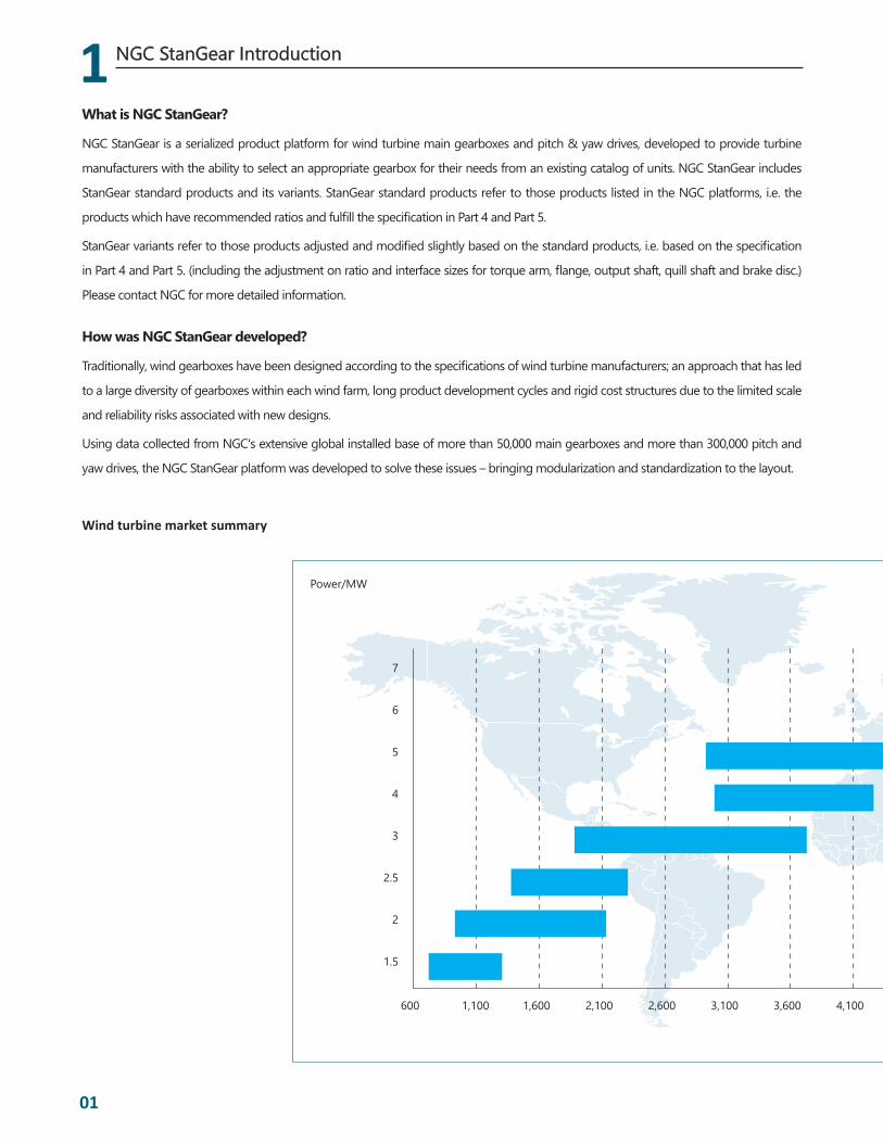
Wind turbine market summary
600 1,100 1,600 2,100 2,600 3,100 3,600 4,100
Power/MW
7
6
5
4
3
2.5
2
1.5

02
1
1NGC StanGear Introduction
Nominal Torque/kNm
4,600 5,100 5,600 5,100 7,100 8,1005,600 7,600 8,600
What benefits does NGC StanGear bring for the customer?
• Reduced cost of new product development
• Less time needed to bring new products to market
• Higher reliability
• Optimized service
How is NGC StanGear used by turbine manufacturers?
Using the NGC StanGear catalog, turbine designers can quickly select a gearbox that will meet their requirements exactly, or understand
which gearboxes will work with the minimum amount of required modifications. To realize the maximum benefits for the whole turbine
drive train, slight adjustments to the turbine design may be required.
2
03
2.1 Performance Standards
• NGC StanGear is in accordance with IEC 61400
• Accuracy of gears are in accordance with ISO 1328-1995, cylindrical gear accuracy system
• Strength ratings of the gears are in accordance with ISO 6336-1996, spur gear & helical gear bearing calculation
method
• Material and heat treatment quality control is in accordance with ISO 6336-5:1996, spur gear and helical gear
bearing calculation method & to the strength and quality ratings of Part 5
2.2 Characteristics
• Newly developed NGC StanGear platform for wind turbine Main Gearboxes
• Modular design technology offers a reduced variety of parts
• High density and lightweight design
• High reliability design
• Advanced design tools including 2D & 3D drawings tools
• Optimized sealing design
• Advanced design software
• Easily customizable to meet the customers' requirements
2.3 Important Notes
• The illustrations in this catalog serve only as an example and are non-binding
• Upon delivery, gear units must be filled with oil prior to operation
• Please refer to the operating manual for the proper oil filling procedure. Viscosity and types of lubrication should
correspond with the nameplate recommendation
• Data regarding oil quantity is non-binding and the actualoil quantity should be adjusted to the oil level mark on
the provided gauge
• Proper guards on all rotating parts should be installed to prevent accidental exposure. Please obey the local and
existing safety requirements
• Lubrication, seals, surface protection and other gear unit characteristics should be adjusted according to the
actual working conditions
• Gear unit maintenance should be in accordance with the operating instructions
• Please contact NGC in the case that designs need to be accordance with GL
• Please contact NGC for any additional information
• The maintenance of gear unit should be in accordance with the operation instruction.
• Please contact NGC, in case customer needs to design according to GL.
Performance Standards \ Characteristics \ Important Notes
General Information
2
2
04
Explanation of Symbols \ Scope of supply
General Information
• Please contact NGC for any other than above matters.
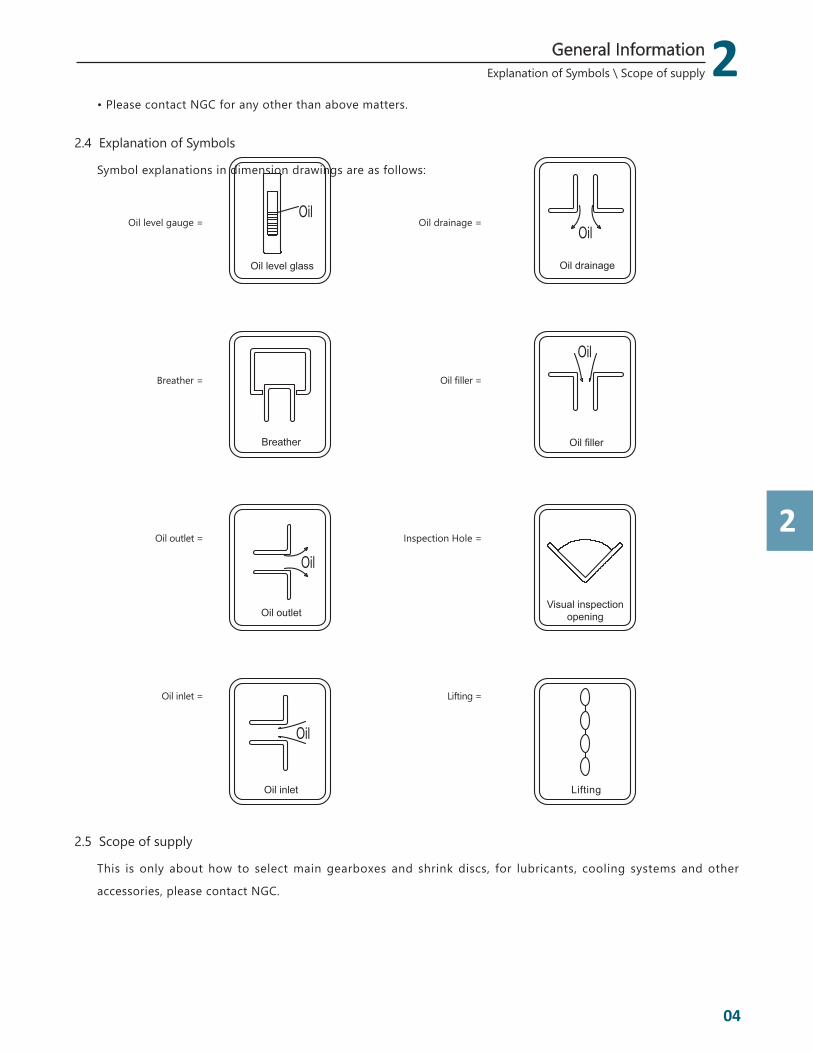
2.4 Explanation of Symbols
Symbol explanations in dimension drawings are as follows:
2.5 Scope of supply
This is only about how to select main gearboxes and shrink discs, for lubricants, cooling systems and other
accessories, please contact NGC.
Oil drainage
Oil
Oil filler
Oil
Oil outlet
Oil
Oil inlet
Oil
Breather
Oil level glass
Oil
Lifting
Visual inspectionopening
Oil filler =
Oil level gauge =
Oil inlet =
Inspection Hole =
Breather =
Oil outlet =
Oil drainage =
Lifting =
3
05
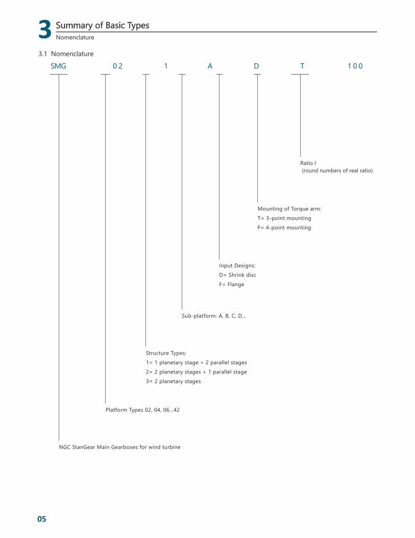
Ratio I (round numbers of real ratio)
Mounting of Torque arm:T= 3-point mountingF= 4-point mounting
Input Designs: D= Shrink discF= Flange
Sub-platform: A, B, C, D…
Structure Types:1= 1 planetary stage + 2 parallel stages2= 2 planetary stages + 1 parallel stage3= 2 planetary stages
Platform Types 02, 04, 06…42
NGC StanGear Main Gearboxes for wind turbine
3.1 Nomenclature
Nomenclature
Summary of Basic Types
SMG 0 2 1 A D T 1 0 0

3
3
06
3.2 Classification of Product
Types Types of Input Mounting of torque arm
1 planetary stage + 2 parallel stages Gear Units
Types: SMG…1…Ratio Range: 71 - 140
Shrink Disc
SMG…1…DT3-point mounting
SMG…1…DF4-point mounting
2 planetary stages + 1 parallel stage Gear Units
Types: SMG…2…Ratio Range: 90 - 150
Shrink Disc
SMG…2…DT3-point mounting
SMG…2…DF4-point mounting
Flange
SMG…2…FT3-point mounting
SMG…2…FF4-point mounting
2 planetary stages gearbox Gear Units
Typs:SMG…3…Ratio Range: consulting
NGC
Flange
SMG…3…FT3-point mounting
SMG…3…FF4-point mounting
Classification of Product
Summary of Basic Types

4
07
4.1 Methods of Selection
Step 1: Determination original input situation
(1) Requirement of gear units
Input power P1=_____kW, Input torque T1_____kNm,
Input speed n1=_____rpm, Output speed n2=_____rpm;
Structure: _____ (1 planetary stage + 2 parallel stages, 2 planetary stages + 1 planetary stage, 2 planetary
stages);
Type of input shaft: _____ (shrink disc, flange)
Mounting of torque arm_____ (3-point mounting, 4-point mounting); Required ratio: i= n1/n2=_____.
Step 2: Selecting gear unit type acc.to Nominal input torque
Nominal input torque of main gearboxes for wind turbine is calculated per certain inner conditions. Input torque
of selected gearbox should meet following prerequisites:
For NGC StanGear main gearboxes, the max. rated torque is calculated per certain inner conditions. The rated
torque of selected gearbox should meet following prerequisites:
T1=(9.55×P1)/n1 ≤ Tn
T1 – Rated input torque, kNm Tn – Max. rated torque, kNm,see table 1, 2, 3
P1 – Rated input power, kW n1 – Input speed, rpm
Refer to table 1 – 3 and determine appropriate main gearboxes platform according to calculated input torque
and required structure type.
Step 3: Determining Sub-platform
Refer to table 1~8 and determine sub-platform (A, B, C, D…) according to the original ratio and the platform,
structure type defined in Step 2.
Step 4: Determining input design
Refer to table 5, 7, 8 and determine input design_____(shrink disc or flange) according to the original ratio and the
platform, structure type defined in Step1, 2.
Step 5: Determining torque arm mounting method
Refer to table 4, 6, 8 and determine torque arm mounting method_____(3-point mounting or 4-point mounting)
according to the original ratio and the platform, structure type defined in Step1, 2.
Step 6: summary of selection information
According to the above information, the conclusion is:
Type of Gearbox: _____ Rated input torque: _____ Ratio: _____ Input speed n1=_____rpm
Step 7: Checking and revising the selections
Detailed load documents shall be provided to NGC for calculating and checking. If the required load is quite
different with the rated input torque, NGC will recommend bigger or smaller type according to the calculation.
Methods of Selection
Selection of Gear Units
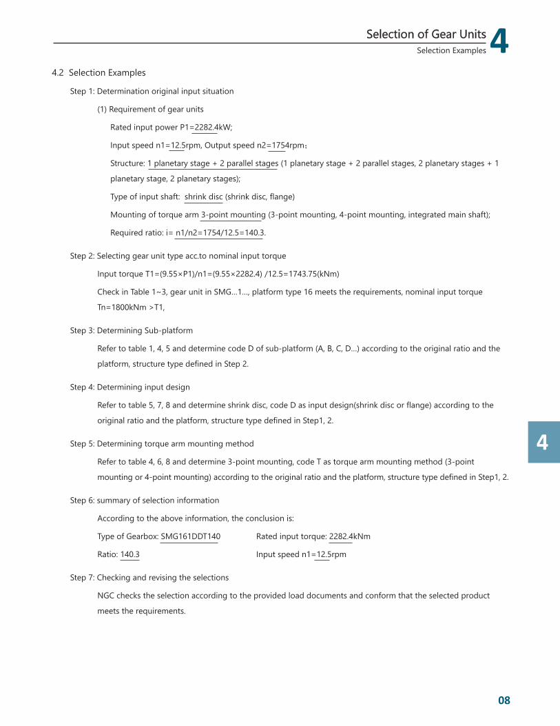
4.2 Selection Examples
Step 1: Determination original input situation
(1) Requirement of gear units
Rated input power P1=2282.4kW;
Input speed n1=12.5rpm, Output speed n2=1754rpm;
Structure: 1 planetary stage + 2 parallel stages (1 planetary stage + 2 parallel stages, 2 planetary stages + 1
planetary stage, 2 planetary stages);
Type of input shaft: shrink disc (shrink disc, flange)
Mounting of torque arm 3-point mounting (3-point mounting, 4-point mounting, integrated main shaft);
Required ratio: i= n1/n2=1754/12.5=140.3.
Step 2: Selecting gear unit type acc.to nominal input torque
Input torque T1=(9.55×P1)/n1=(9.55×2282.4) /12.5=1743.75(kNm)
Check in Table 1~3, gear unit in SMG…1…, platform type 16 meets the requirements, nominal input torque
Tn=1800kNm >T1,
Step 3: Determining Sub-platform
Refer to table 1, 4, 5 and determine code D of sub-platform (A, B, C, D…) according to the original ratio and the
platform, structure type defined in Step 2.
Step 4: Determining input design
Refer to table 5, 7, 8 and determine shrink disc, code D as input design(shrink disc or flange) according to the
original ratio and the platform, structure type defined in Step1, 2.
Step 5: Determining torque arm mounting method
Refer to table 4, 6, 8 and determine 3-point mounting, code T as torque arm mounting method (3-point
mounting or 4-point mounting) according to the original ratio and the platform, structure type defined in Step1, 2.
Step 6: summary of selection information
According to the above information, the conclusion is:
Type of Gearbox: SMG161DDT140 Rated input torque: 2282.4kNm
Ratio: 140.3 Input speed n1=12.5rpm
Step 7: Checking and revising the selections
NGC checks the selection according to the provided load documents and conform that the selected product
meets the requirements.
4
4
08
Selection Examples
Selection of Gear Units

4
09
Nominal input torques and Ratios
4.3 Nominal input torques and Ratios
SMG…1… (1 planetary stage + 2 parallel stages)
Platform Types Nominal input torque Tn(kNm) Sub-platform Recommended ratio Ratio Range
06 1000A 94.73 99.74 104.08 109.97 80-120
B 89.47 111.54 - - 71-120
08 1120 A 116.26 - - - 80-120
10 1240 A 106.05 107.08 118.63 - 71-120
12 1400 A 118.40 124.90 - - 90-130
14 1600A 118.40 - - - 90-130
B 91.44 - - - 90-130
16 1800
A 90.13 - - - 90-130
B 91.65 127.00 130.60 - 90-130
C 102.87 117.62 131.58 140.30 100-140
D 131.47 133.00 - - 100-140
Table 1
Selection of Gear Units

4
4
10
Nominal input torques and Ratios
Selection of Gear Units
SMG…2… (2 planetary stages + 1 parallel stage)
Platform Types Nominal input torque Tn(kNm) Sub-platform Recommended ratio Ratio Range
06 1000 A 100.48 105.13 108.32 - 90-150
08-12 1120-1400 A Consulting NGC
16 1800 A 104.31 111.99 130.15 147.54 100-150
18 2000 A 103.98 130.03 - - 100-130
20 2240 A 97.94 118.39 - - 90-120
22 2500 A 102.20 102.40 113.46 127.23 100-130
24 2800 A 143.77 150.20 - - 110-150
26 3150 A 84.26 90.96 - - 80-110
28-42 3550-8000 A Consulting NGC
Table 2
SMG…3… (2 planetary stages)
Platform Types Nominal input torque Tn(kNm) Sub-platform Recommended ratio Ratio Range
16 1800 A 38.15 - - - Consulting NGC
22 2500 A 38.33 - - - Consulting NGC
Table 3
Note: 1. If the required ratio is not in the table, please consult NGC
5
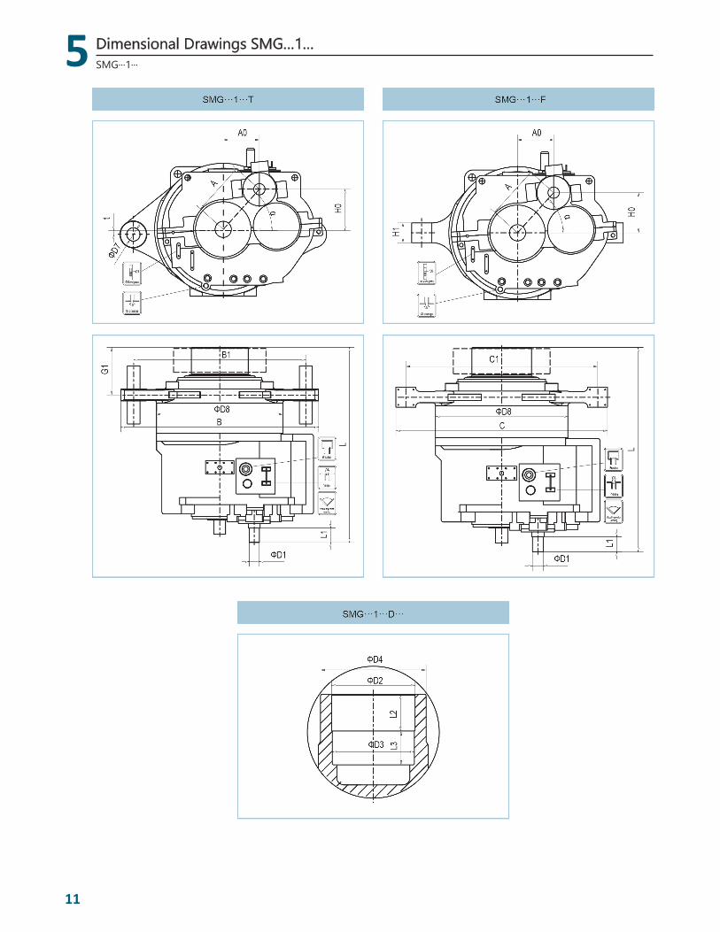
11
SMG···1···
Dimensional Drawings SMG…1…

5
5
12
SMG···1···
Dimensional Drawings SMG…1…
Platform Types
Sub-Platform
Gear Unit SMG…1… Torque arm with 3-point mounting Torque arm with 4-point mounting
A A0 H0 α° ΦD8 G1 B B1 ΦD7 tG1 C C1 H1
06 A 615 - - 45 1680 595 2650 2300 200 0 - - - -
06 B - 600 0 - 1594 485 2600 2250 200 0 - - - -
08 A 615 - - 45 1680 595 2650 2300 200 0 - - - -
10 A 615 - - 45 1594 595 2650 2300 200 0 - - - -
12 A - 460.2 485.6 - 1715 603.5 2500 2180 160 0 - - - -
14 A - 460.2 485.6 - 1715 603.5 2500 2180 160 0 - - - -
14 B - 437.3 485.6 - 1600 603.5 2505 2180 160 225 - - - -
16 A - 437.3 485.6 - 1715 623 2592 2272 160 0 - - - -
16 B 700 - - 44.944 1715 603.5 2980 2600 220 0 - - - -
16 C 710 340 - - 1890 - - - - 0 633 2880 2650 320
16 D - 460.2 550 - 1795 603.5 2815 2400 220 0 - - - -
Table 4
Platform Types
Sub-Platform
Input of Shrink Disc Output ShaftOil quantity (L)
ΦD3 ΦD4 L2 L3 L ΦD1 L1
06 A 520 510 640 255 245 2190 120 160 330
06 B 520 510 640 195 215 2175 125 1250 290
08 A 520 510 640 255 245 2190 120 160 330
10 A 520 510 640 255 245 2190 120 160 290
12 A 630 620 750 280 230 2461 130 160 390
14 A 570 - 720 480 - 2451 130 160 390
14 B 570 - 720 480 - 2551 130 260 360
16 A 570 - 720 480 - 2451 130 160 360
16 B 570 - 720 346 - 2441 140 160 400
16 C 560 550 700 310 300 2495 130 180 400
16 D 620 - 750 480 - 2451 130 1660 390
Table 5
Note: Should any difference between the dimensions in this brochure and what customers required, please consult
NGC
5
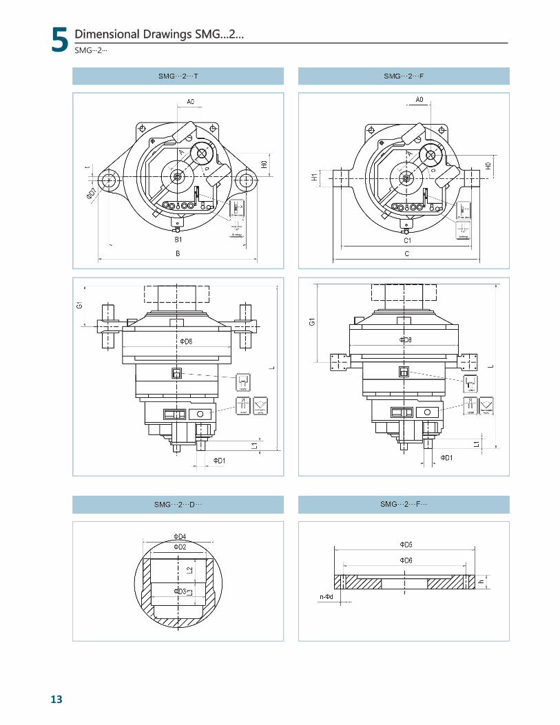
13
SMG···2···
Dimensional Drawings SMG…2…
5
5
14
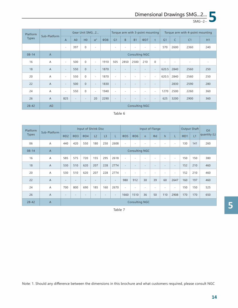
SMG···2···
Platform Types Sub-Platform
Gear Unit SMG…2… Torque arm with 3-point mounting Torque arm with 4-point mounting
A A0 H0 α° ΦD8 G1 B B1 ΦD7 t G1 C C1 H1
- 397 0 - - - - - - 570 2600 2360 240
08-14 A Consulting NGC
16 A - 500 0 - 1910 505 2850 2500 210 0 - - - -
18 A - 550 0 - 1870 - - - - - 620.5 2840 2560 250
20 A - 550 0 - 1870 - - - - - 620.5 2840 2560 250
22 A - 500 0 - 1830 - - - - - 2830 2590 280
24 A - 550 0 - 1940 - - - - - 1270 2500 2260 360
26 A 825 - - 20 2290 - - - - - 625 3200 2900 360
28-42 A Consulting NGC
Table 6
Platform Types Sub-Platform
Input of Shrink Disc Input of Flange Output Shaft Oil quantity (L)ΦD2 ΦD3 ΦD4 L2 L3 L ΦD5 ΦD6 n Φd h L ΦD1 L1
06 A 440 420 550 180 250 2608 - - - - - - 130 141 260
08-14 A Consulting NGC
16 A 585 575 720 155 295 2618 - - - - - - 150 150 380
18 A 530 510 620 207 228 2774 - - - - - - 152 210 460
20 A 530 510 620 207 228 2774 - - - - - - 152 210 460
22 A - - - - - - 980 912 30 39 60 2647 160 197 460
24 A 700 800 690 185 160 2670 - - - - - - 150 150 525
26 A - - - - - - 1660 1510 36 50 110 2908 170 170 650
28-42 A Consulting NGC
Table 7
Note: 1. Should any difference between the dimensions in this brochure and what customers required, please consult NGC
Dimensional Drawings SMG…2…

5
15
Platform Types
Sub-Platform
Gear Unit SMG…3… Torque arm with 4-point mounting Input of Flange Oil
quantity (L)L1 L2 L ΦD8 G1 C C1 H1 ΦD5 ΦD6 ΦD9 n Φd h
16 A 1639 1733.5 1904 2010 950 2800 2560 240 1200 1100 940 42 39 115 400
22 A 1868 1968 2143 2060 1408 3100 2800 320 1200 1100 940 42 39 100 500
Table 8
Note: Should any difference between the dimensions in this brochure and what customers required, please consult NGC
SMG···3···
Dimensional Drawings SMG…3…
6
6
16
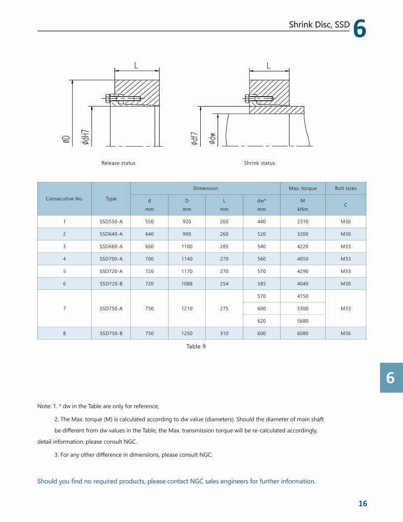
Shrink Disc, SSD
Release status Shrink status
Consecutive No. Type
Dimension Max. torque Bolt sizes
dmm
Dmm
Lmm
dw*mm
MkNm
C
1 SSD550-A 550 920 260 440 2310 M30
2 SSD640-A 640 990 260 520 3200 M30
3 SSD660-A 660 1100 285 540 4220 M33
4 SSD700-A 700 1140 270 560 4050 M33
5 SSD720-A 720 1170 270 570 4290 M33
6 SSD720-B 720 1088 254 585 4040 M30
7 SSD750-A 750 1210 275
570 4750
M33600 5300
620 5680
8 SSD750-B 750 1250 310 600 6080 M36
Table 9
Note: 1. * dw in the Table are only for reference;
2. The Max. torque (M) is calculated according to dw value (diameters). Should the diameter of main shaft
be different from dw values in the Table, the Max. transmission torque will be re-calculated accordingly.
detail information, please consult NGC.
3. For any other difference in dimensions, please consult NGC.
Should you find no required products, please contact NGC sales engineers for further information.
Note: The model numbers and parameters will be updated occasionally without notice, please refer to the latest NGC brochure.
Wind EnergyAdd: No.299 LaiYinDa Road, JiangNing District, NanJing, 211100, PR ChinaTel: +86 25 52172849 Fax: +86 25 52172926Email: [email protected]
Headquarters
RHQ NGC AmericaNGC Transmission Equipment (America), Inc. Add: 5500 Alliance Gateway Freeway, Fort Worth, Texas 76177, USATel: +1 817 567 7499 Fax: +1 817 567 7495Email: [email protected]
RHQ NGC Asia PacificNGC Transmission Asia Pacific Pte. Ltd.Add: 51 Changi Business Park Central 2, #06-08, The Signature, Singapore 486066Tel: +65 6589 8588 Fax: +65 6588 3557Email: [email protected]
NGC IndiaNGC Transmission India Pvt. Ltd.Add: DG Square, Unit 6A, 127 Pallavaram – Thoraipakkam 200 Feet Radial Road, Kilkattalai, Chennai 600117Tel: +91 44 6612 3500 Fax: +91 44 6612 3535 Email: [email protected]
NGC VietnamNGC Transmission Vietnam Pte. Ltd.Add: Suite 2304, Floor 23th West Tower, Lotte Center Hanoi, 54 Lieu Giai, Cong Vi Ward, Ba Dinh District, Hanoi City, VietnamEmail: [email protected]
RHQ NGC EuropeNGC Transmission Europe GmbHAdd: Schifferstrasse 196, 47059 Duisburg, GermanyTel: +49 203 509 600 0 Fax: +49 203 509 601 90Email: [email protected]
Oversea Business
Contact Us
Version: 201701ENHK Stock Code: 658www.NGCamericas.com