Embed Size (px)
Citation preview

MAHARASHTRA STATE BOARD OF TECHNICAL EDUCATION
(Autonomous)
(ISO/IEC - 27001 - 2005 Certified)
SUMMER – 2016 EXAMINATION
Subject Code: 17519 Model Answer Page No: 1/32
Important Instructions to examiners:
1) The answers should be examined by key words and not as word-to-word as given in the model
answer scheme.
2) The model answer and the answer written by candidate may vary but the examiner may tryto
assess the understanding level of the candidate.
3) The language errors such as grammatical, spelling errors should not be given more importance
(Not applicable for subject English and Communication Skills.
4) While assessing figures, examiner may give credit for principal components indicated in the
figure. The figures drawn by candidate and model answer may vary. The examiner may give
credit for any equivalent figure drawn.
5) Credits may be given step wise for numerical problems. In some cases, the assumed
constantvalues may vary and there may be some difference in the candidate‟s answers and model
answer.
6) In case of some questions credit may be given by judgement on part of examiner of relevant
answer based on candidate‟s understanding.
7) For programming language papers, credit may be given to any other program based on
equivalent concept.
Q.1A) Attempt any three: 12M
a) Define Modulation. Why it is necessary?
(Definition 1Mark, Need of Modulation 3Marks)
Ans:
Modulation:
It is a process in which the amplitude, frequency or phase of carrier signal is varied in
accordance with the instantaneous amplitude of the modulating signal.
or
It is a process in which the low frequency information signal is superimposed on a high
frequency carrier signal.
Need of Modulation: 1. Reduction in height of antenna: For transmission of radio signals ,antenna height must be multiple of (λ/4). Minimum height required to transmit a baseband signal of f=10 KHz is calculated as Minimum height of antenna = λ/4=c/4f=7.5Km. The antenna of this height is practically impossible to install Minimum height required to transmit a baseband signal of f=1MHz is calculated as Minimum height of antenna = λ/4=c/4f=75m.

MAHARASHTRA STATE BOARD OF TECHNICAL EDUCATION
(Autonomous)
(ISO/IEC - 27001 - 2005 Certified)
SUMMER – 2016 EXAMINATION
Subject Code: 17519 Model Answer Page No: 2/32
Thus modulation is necessary to reduce the height of antenna. 2. Avoids mixing of signals: If the baseband sound signals are transmitted without using the modulation through more than one transmitter, then all signals will be in frequency 0 to 20 KHz. Therefore all the signals get mixed together and a receiver cannot separate them from each other. So if the baseband signal is used to modulate different carrier then they will occupy different slots in frequency domain. Thus modulation is necessary to avoid mixing of signals. 3. Increases range of communication: The frequency of baseband signal is low and thus the
low frequency signal cannot travel a long distance when they are transmitted they get heavily
attenuated. The attenuation reduces with increase in frequency of the transmitted signal and they
can travel longer distance.
4. Makes multiplexing possible: Multiplexing is the process in which two or more signals can
be transmitted over same communication channel simultaneously. This is possible only with
modulation. Therefore many TV channel can use same frequency range without getting mixed
with each other.
5. Improves quality of reception: With FM and digital communication technique like PCM, the
effect of noise is reduced to a great extent.
b) Draw the waveform for FSK and PSK modulation.
(FSK Waveform 2Marks, PSK Waveform 2 Marks)
Note: Any other relevant data shall be considered for drawing waveform.
Ans:
FSK Modulation

MAHARASHTRA STATE BOARD OF TECHNICAL EDUCATION
(Autonomous)
(ISO/IEC - 27001 - 2005 Certified)
SUMMER – 2016 EXAMINATION
Subject Code: 17519 Model Answer Page No: 3/32
PSK Modulation
c) Draw block diagram of TDMA. Describe its working.
(Diagram 2 Marks, Working 2Marks)
Ans:
MAHARASHTRA STATE BOARD OF TECHNICAL EDUCATION
(Autonomous)
(ISO/IEC - 27001 - 2005 Certified)
SUMMER – 2016 EXAMINATION
Subject Code: 17519 Model Answer Page No: 4/32
In TDMA the stations share the bandwidth of the channel in time. Each station is allocated a time
slot during which it can send data. Each station transmits its data in the assigned time slots. In
TDMA the bandwidth is just one channel that is time shared between different stations. It is an
access method in the data link layer. The data link layer in each station tells its physical layer to
use the allocated time slot. There is no physical multiplexer at the physical layer.
The main problem with TDMA lies in achieving synchronization between the different stations.
Each station needs to know the beginning of its slot and the location of each slot. This may be
difficult because of propagation delays introduced in the system if the stations are spread over a
large area. To compensate fort the delays we can insert guard times. Synchronization is normally
accomplished by having some synchronization bits at the beginning of each slot.
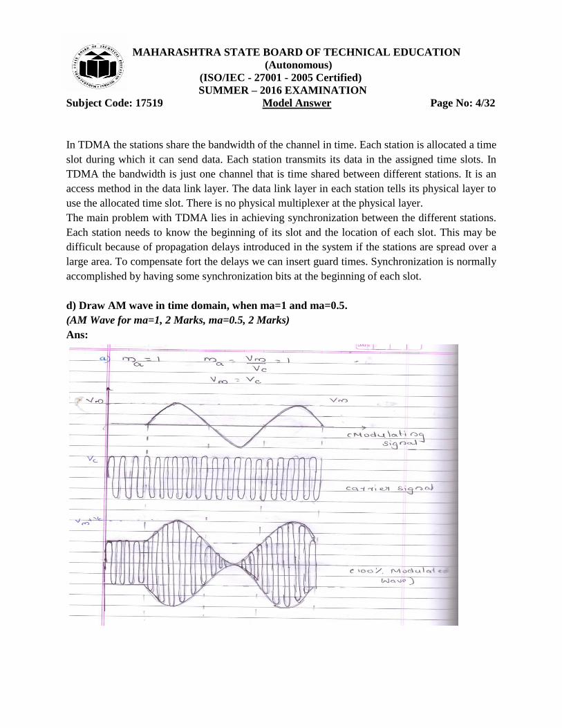
d) Draw AM wave in time domain, when ma=1 and ma=0.5.
(AM Wave for ma=1, 2 Marks, ma=0.5, 2 Marks)
Ans:

MAHARASHTRA STATE BOARD OF TECHNICAL EDUCATION
(Autonomous)
(ISO/IEC - 27001 - 2005 Certified)
SUMMER – 2016 EXAMINATION
Subject Code: 17519 Model Answer Page No: 5/32

MAHARASHTRA STATE BOARD OF TECHNICAL EDUCATION
(Autonomous)
(ISO/IEC - 27001 - 2005 Certified)
SUMMER – 2016 EXAMINATION
Subject Code: 17519 Model Answer Page No: 6/32
Q.1B) Attempt any one: 6M
a) A transmitter transmits 10kW of power without modulation and 12kW after amplitude
modulation. What is the modulation index?
(Each Correct Step 1 Mark)
Ans:
b) Draw and explain QPSK modulator.
(Block Diagram 2 Marks, Explanation 2 Marks, Waveform 2 Marks)
Ans:
Quadrature Phase Shift Keying or Quaternary Phase shift Keying
1. QPSK is an example of multilevel phase modulation.
2. With QPSK four output phases are possible for a single carrier frequency.
3. Since four output phases are present, there must be four different input conditions.
4. With two bits there are four possible conditions. 00, 01, 10, 11 are possible.
5. With QPSK the binary input data are combined into groups of two bits called dibits.
6. Each dibit code generates one of the four possible output phases (+45o, +135
o, -45
o, -135
o)

MAHARASHTRA STATE BOARD OF TECHNICAL EDUCATION
(Autonomous)
(ISO/IEC - 27001 - 2005 Certified)
SUMMER – 2016 EXAMINATION
Subject Code: 17519 Model Answer Page No: 7/32
1. Two bits (a, dibit) are clocked into the bit splitter.
2. One bit is directed to the I channel and the other to Q channel.
3. The I bit modulates a carrier that is in phase reference oscillator (hence the name “I” for in
phase channel).
4. The Q bit modulates a carrier that is 90o out of phase OR in quadrature with the reference
carrier (hence the name “Q” for “quadrature channel.
5. A QPSK modulator is two BPSK modulators combined in parallel.
6. For a logic 1 = + 1V
Logic 0 = - 1V
two phases are possible at the output of the I balanced modulator. (+Sin wc t, Sin wc t), and two
phases are possible at the output of the Q balanced modulator (+Cos wc t, -Cos wc t). When the
linear summer combines the two quadrature (90o out of phase signals) there are four possible
resultant phases given by these expressions:
+ Sin wc t + Cos wc t
+ Sin wc t - Cos wc t
- Sin wc t + Cos wc t
+ Sin wc t - Cos wc t

MAHARASHTRA STATE BOARD OF TECHNICAL EDUCATION
(Autonomous)
(ISO/IEC - 27001 - 2005 Certified)
SUMMER – 2016 EXAMINATION
Subject Code: 17519 Model Answer Page No: 8/32
Output waveform

MAHARASHTRA STATE BOARD OF TECHNICAL EDUCATION
(Autonomous)
(ISO/IEC - 27001 - 2005 Certified)
SUMMER – 2016 EXAMINATION
Subject Code: 17519 Model Answer Page No: 9/32
Q.2 Attempt any four: 16M
a) Draw the block diagram of standard telephone system. Describe its functions.
(Diagram 2 Marks, Functions 2 Marks)
Ans:
The telephone system permits any telephone to connect with any other telephone in the world.
This means that each telephone must have a unique identification code- the 10 digit telephone
number assigned to each telephone, the telephone system provides a means of recognizing each
individual number and switching system that can connect any switching systems that can
connect any two telephones. The local loop Standard telephones are connected to then telephone
system by way of a two-wire, twisted pair cable that terminates at the local exchange or central
office. As many as 10000 telephone line can be connected to single central office. Then
connections from then central office go to then “telephone system‟. A call originating at
telephone A will pass through the central office and then into the main system where it is
transmitted via one of many different routes to the central office connected to the desired
location designated as B. The connection between nearby local exchange is direct rather than
long distance. The two wire twisted pair connection between the telephones and the central
office is referred to as the local loop or subscriber loop. All dialing and signaling operations are
also carried on this shingle twisted pair. A basic telephones or telephone set is an analog
baseband transceiver. It has a handset which contains a microphone and a speaker, better known
as a transmitter and a receiver. It also contains a ringer and a dialing mechanism.

MAHARASHTRA STATE BOARD OF TECHNICAL EDUCATION
(Autonomous)
(ISO/IEC - 27001 - 2005 Certified)
SUMMER – 2016 EXAMINATION
Subject Code: 17519 Model Answer Page No: 10/32
b) Draw the block diagram of FM receiver. State the function and each block.
(Diagram 2 Marks, Functions 2 Marks)
Ans:
Functions:
1. RF Amplifier:
Its function is
To improve the signal to noise ratio.
To march the receiver input impedance to antenna impedance.
To reduce noise figure.
2. Mixer:
It is also known as frequency changer. Input signal frequency fs and local oscillator frequency f0
are mixed to down convert the received signal to intermediate frequency (IF).
IF = f0 - fs
IF = 10.7 MHz
3. IF Amplifiers:
It amplifies the IF of mixer output. Due to large bandwidth gain per stage is low. Therefore two
or more stages of IF amplifiers are used.
4. Amplitude Limiter:
It removes the unwanted amplitude that added in original FM signal while travelling in free
space. It is removed before demodulation, otherwise distortion appears at the output.

MAHARASHTRA STATE BOARD OF TECHNICAL EDUCATION
(Autonomous)
(ISO/IEC - 27001 - 2005 Certified)
SUMMER – 2016 EXAMINATION
Subject Code: 17519 Model Answer Page No: 11/32
5. FM Detector:
It converts the FM signal into original modulating signal.
6. De-emphasis:
The artificially boosted high frequencies at transmitter are removed by de-emphasis.
7. AF and Power Amplifier:
First the modulating signal is voltage amplified and its power is increased to drive the
loudspeaker.
8. AGC:
Automatic gain control is used to ensure that the signal fit to the limiter is within its limiting
range and also prevents overloading of last IF amplifier.
9. Loudspeaker:
It converts modulating signal into sound information.
c) Draw neat block diagram of delta modulator. Describe its operation.
(Diagram-2Marks & Explanation-2Marks)
Ans:

MAHARASHTRA STATE BOARD OF TECHNICAL EDUCATION
(Autonomous)
(ISO/IEC - 27001 - 2005 Certified)
SUMMER – 2016 EXAMINATION
Subject Code: 17519 Model Answer Page No: 12/32
The above diagram shows a block diagram of a delta modulation transmitter. The analog input is
sampled and converted to a PAM signal, which is compared with the output of the DAC. The
output of DAC is a voltage equal to the regenerated magnitude of the previous sample, which
was stored in the up-down counter as a binary number. The up-down counter is incremented or
decremented depending on whether the previous sample is larger or smaller than the current
sample. The up-down counter is clocked at a rate equal to sample rate. Therefore, the up-down
counter is updated after each comparison. Initially, the up-down counter is zeroed, and the DAC
is outputting 0V. The first sample is taken, converted to PAM signal, and compare with zero
volts. The output of the comparator is a logic 1 condition (+V), indicating that the current
sample is larger in amplitude than the previous sample. On the next clock pulse, the up-down
counter is incremented to a count of 1. The DAC now outputs a voltage equal to the magnitude
of the minimum step size (resolution). The steps change value at a rate equal to the clock
frequency (sample rate). Consequently, with the input signal shown, the up-down counter
follows the input analog signal up until the output of the DAC exceeds the analog sample; then
the up-down counter will begin counting down until the output of the DAC drop below the
sample amplitude. In the idealized situation, The DAC output follows the input signal. Each time
the up-down counter is incremented, logic 1 is transmitted, and each time the up-down counter is
decremented, logic 0 is transmitted.
d) Consider the data stream 11011010 and encode using,
i) Unipolar NRZ ii) Bipolar NRZ
(Correct encoding for Unipolar NRZ 2 Marks, Bipolar NRZ 2Marks)
Ans:

MAHARASHTRA STATE BOARD OF TECHNICAL EDUCATION
(Autonomous)
(ISO/IEC - 27001 - 2005 Certified)
SUMMER – 2016 EXAMINATION
Subject Code: 17519 Model Answer Page No: 13/32
e) Draw the block diagram and explain the working of FDM.
(Diagram 2Marks, Working 2 Marks)
Ans:
Modulation:
Demodulation:
In FDM, signal generated by each sending device modulate different carrier frequencies. These
modulated signals are combined into a single composite signal that can be transported by the
link. Carrier frequencies are separated by guard bands to prevent over- lapping of signal. Though
it is an analog multiplexing system, digital signals can also be sending by converting them into
analog signals.
The demux uses a series of filters to decompose the multiplexed signal into its constituent carrier
signals. These modulated carrier signals are passed through demodulators to separate them from
their carrier and then are passed to their output lines.

MAHARASHTRA STATE BOARD OF TECHNICAL EDUCATION
(Autonomous)
(ISO/IEC - 27001 - 2005 Certified)
SUMMER – 2016 EXAMINATION
Subject Code: 17519 Model Answer Page No: 14/32
f) Draw the block diagram of digital communication system.
(Correct Diagram 4Marks)
Ans:
MAHARASHTRA STATE BOARD OF TECHNICAL EDUCATION
(Autonomous)
(ISO/IEC - 27001 - 2005 Certified)
SUMMER – 2016 EXAMINATION
Subject Code: 17519 Model Answer Page No: 15/32
Q.3 Attempt any four: 16M
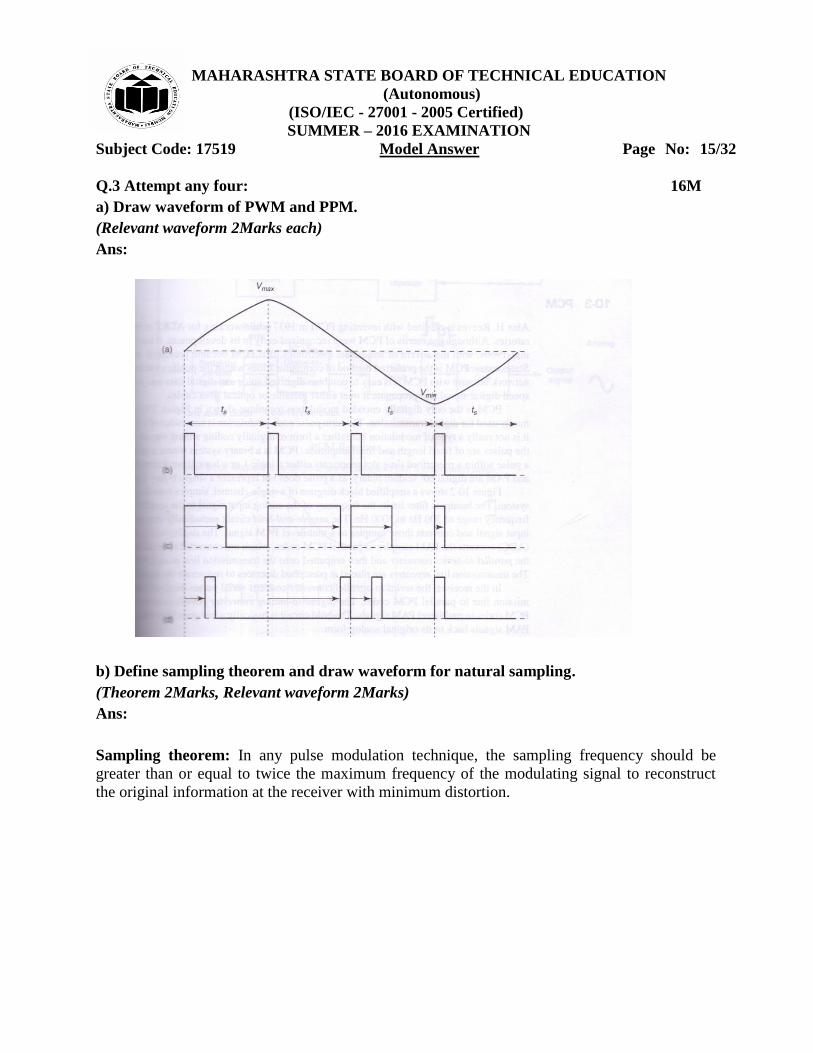
a) Draw waveform of PWM and PPM.
(Relevant waveform 2Marks each)
Ans:
b) Define sampling theorem and draw waveform for natural sampling.
(Theorem 2Marks, Relevant waveform 2Marks)
Ans:
Sampling theorem: In any pulse modulation technique, the sampling frequency should be
greater than or equal to twice the maximum frequency of the modulating signal to reconstruct
the original information at the receiver with minimum distortion.

MAHARASHTRA STATE BOARD OF TECHNICAL EDUCATION
(Autonomous)
(ISO/IEC - 27001 - 2005 Certified)
SUMMER – 2016 EXAMINATION
Subject Code: 17519 Model Answer Page No: 16/32
Waveform for Natural sampling
c) What is multiplexing? State different types of multiplexing techniques used.
(Definition-2Marks & Any two types–2Marks )
Ans:
Multiplexing: It is process of simultaneously transmitting two or more individual signals over
single communication channel.
Types of multiplexing:
1. Frequency Division Multiplexing (FDM)
2. Time Division Multiplexing (TDM)
3. Wavelength Division Multiplexing (WDM)
MAHARASHTRA STATE BOARD OF TECHNICAL EDUCATION
(Autonomous)
(ISO/IEC - 27001 - 2005 Certified)
SUMMER – 2016 EXAMINATION
Subject Code: 17519 Model Answer Page No: 17/32
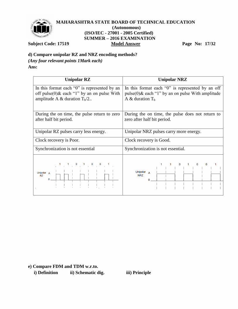
d) Compare unipolar RZ and NRZ encoding methods?
(Any four relevant points 1Mark each)
Ans:
Unipolar RZ Unipolar NRZ
In this format each “0” is represented by an
off pulse(0)& each “1” by an on pulse With
amplitude A & duration Tb/2..
In this format each “0” is represented by an off
pulse(0)& each “1” by an on pulse With amplitude
A & duration Tb
During the on time, the pulse return to zero
after half bit period.
During the on time, the pulse does not return to
zero after half bit period.
Unipolar RZ pulses carry less energy. Unipolar NRZ pulses carry more energy.
Clock recovery is Poor. Clock recovery is Good.
Synchronization is not essential Synchronization is not essential.
e) Compare FDM and TDM w.r.to.
i) Definition ii) Schematic dig. iii) Principle

MAHARASHTRA STATE BOARD OF TECHNICAL EDUCATION
(Autonomous)
(ISO/IEC - 27001 - 2005 Certified)
SUMMER – 2016 EXAMINATION
Subject Code: 17519 Model Answer Page No: 18/32
(Definition 2Marks, Relevant Diagram 1Mark, Principle 1Mark)
Ans:
FDM TDM
Definit
ion
Frequency-division multiplexing (FDM) is
an analog technique where total range of
frequency is divided into number of
frequency slots. Each slot of frequency is
allotted to each channel.
Time-division multiplexing (TDM) is digital
technique to combine data where time is
shared.
Schem
atic
Diagr
am
Princip
le
Various channels of different
frequencies combined, transmitted
through single wire & separated at
receiver with help of demultiplexer.
FDM is applied when bandwidth of a
link is greater than combined bandwidth
of signals to be transmitted.
These modulated signals are then
combined into single composite signal
that can be transported by the link.
Carrier frequencies are separated by
sufficient bandwidth to accommodate
modulated signal.
These bandwidth ranges are channels
through which various signals travels.
Channels must be separated by guard
bands to prevent signals from
overlapping.
Various channels of different frequencies
combined, transmitted through single wire
& separated at receiver with help of
demultiplexer.
Transmission time is divided into number
of time slices.
Then each time slice is allocated to
different source node, each of which wants
to send data.
Data flow of each connection is divided
into units & link combines one unit of each
connection to make a frame.
Data rate of link that carries data from „n‟
connections must be „n‟ times data rate of a
connection to guarantee the flow of data.

MAHARASHTRA STATE BOARD OF TECHNICAL EDUCATION
(Autonomous)
(ISO/IEC - 27001 - 2005 Certified)
SUMMER – 2016 EXAMINATION
Subject Code: 17519 Model Answer Page No: 19/32
Q.4 A) Attempt any three: 12M
a) Describe ionosphere propagation with the help of neat diagram.
(Relevant Diagram 2Marks; Relevant Explanation 2Marks)
Ans:
Electromagnetic waves that are directed above the horizon level are called as sky waves.
Typically, sky waves are radiated in a direction that produces a relatively large angle with
reference to earth. Sky waves are radiated toward the sky, where they are either reflected or
refracted back to earth by the ionosphere. Because of this, sky wave propagation is sometime
called as ionospheric propagation. The ionosphere is the region of space located approximately
50km to 400 km above Earth surface. The ionosphere is the upper portion of earth‟s atmosphere.
Therefore it absorbs large quantities of the sun radiant energy, which ionizes the air molecules,
creating free electrons. When radio wave passes through the ionosphere the electric field of the
wave exerts a force on the free electrons, causing them to vibrate. The vibrating electron
decreases current, which is equivalent to reducing the dielectric constant. Reducing the dielectric
constant increases the velocity of propagation and causes electromagnetic waves to bend away
from the regions of high electron density toward regions of low electron density. As the wave
moves farther from earth ionization increase; however, there are fewer air molecules to ionize.
Therefore, the upper atmosphere has a higher percentage of ionized molecules than the lower
atmosphere. The higher the ion density, the more refraction. Also because of the ionosphere‟s
non uniform composition and its temperature and density variations, it is stratified. Essentially,
three layers makeup the ionosphere (the D, E, Flayers).
b) Draw the waveform for the bit sequence given below:

MAHARASHTRA STATE BOARD OF TECHNICAL EDUCATION
(Autonomous)
(ISO/IEC - 27001 - 2005 Certified)
SUMMER – 2016 EXAMINATION
Subject Code: 17519 Model Answer Page No: 20/32
11001010 using unipolar RZ and polar RZ encoding technique.
(Correct waveform 4 Marks)
Ans:
c) State the two advantages and disadvantages of FSK over ASK.
(Any Two advantages-2Marks & Any two disadvantages-2Marks)
Ans:
Advantages of FSK over ASK:
1. Low noise, since amplitude is constant
2. Power requirement is constant
3. Operates in virtually any wires available
4. High data rate
5. Used in long distance communication
6. Easy to decode
7. Good sensitivity
8. It has high security
9. Efficiency is high.
Disadvantages of FSK over ASK:
1. The major disadvantage is its high bandwidth requirement.

MAHARASHTRA STATE BOARD OF TECHNICAL EDUCATION
(Autonomous)
(ISO/IEC - 27001 - 2005 Certified)
SUMMER – 2016 EXAMINATION
Subject Code: 17519 Model Answer Page No: 21/32
2. Therefore FSK is extensively used in low speed modems having bit rates below 1200
bits/sec.
3. The FSK is not preferred for the high speed modems because with increase in speed, the bit
rate increases.
4. This increases the channel bandwidth required to transmit the FSK signal.
5. As the telephone lines have a very low bandwidth, it is not possible to satisfy the bandwidth
requirement of FSK at higher speed. Therefore FSK is preferred only for the low speed
modems
d) Describe the concept of frequency reuse.
(Concept of frequency reuse 2Marks, Relevant Diagram 2Marks)
Ans:
Frequency reuse-
Frequency reuse is the process in which the same set of frequencies (channels) can be allocated
to more than one cell. Provided the cells are separated by sufficient distance reducing each cells
coverage area invites frequency reuse cells using the same set of radio channels can avoid
mutual interference, provided they are properly separated. Each cell base station is allocated a
group of channel frequencies that are different from those of neighboring cells & base station
antennas are chosen to achieve a desired coverage pattern within its cell. However as long as a
coverage area is limited to within a cells boundaries the same group of channel frequencies may
be used in different cells without interfacing with each other provided the two cells are sufficient
distance from one another.
Q.4 B) Attempt any one: 6M

MAHARASHTRA STATE BOARD OF TECHNICAL EDUCATION
(Autonomous)
(ISO/IEC - 27001 - 2005 Certified)
SUMMER – 2016 EXAMINATION
Subject Code: 17519 Model Answer Page No: 22/32
a) Describe PCM transmitter with the help of neat diagram. What is quantization error?
(Relevant explanation- 2Marks, Diagram – 2Marks & quantization error-2Marks)
Operation of PCM transmitter: i. The analog signal x(t) is passed through a band limiting low pass filter, which has a cut-off
frequency fc =WHz. This will ensure that x(t) will not have any frequency component higher
than “W”. This will eliminate the possibility of aliasing.
ii. The band limited analog signal is then applied to a sample and hold the circuit where it is
sampled at adequately high sampling rate. Output of sample and hold block is a flat topped PAM
signal.
iii. These samples are then subjected to the operation called “Quantization” in the “Quantizer”.
The quantization is used to reduce the effect of noise. The combined effect of sampling and
quantization produces the quantized PAM at the quantizer output.
iv. The quantized PAM pulses are applied to an encoder which is basically an A to D converter.
Each quantized level is converted into an N bit digital word by the A to D converter. The value
of N can be 8,16,32,64 etc.
v. The encoder output is converted into a stream of pulses by the parallel to serial converter
block. thus at the PCM transmitter output we get a train of digital pulses.

MAHARASHTRA STATE BOARD OF TECHNICAL EDUCATION
(Autonomous)
(ISO/IEC - 27001 - 2005 Certified)
SUMMER – 2016 EXAMINATION
Subject Code: 17519 Model Answer Page No: 23/32
Quantization error: The error between the original analog signal & its quantized version which
is measured is called Quantization error.
b) Draw and explain the block diagram of cellular mobile phone system.
(Relevant Explanation 3 Marks & Diagram 3Marks)
Ans:
The five major parts of this system are:
1. Control Unit
2. Logic unit
3. Transmitter
4. Receiver
5. Frequency synthesizer
Functions of each block:
Transmitter: It is low power FM unit operating in the frequency range of 825 to 845MHz. There are
666, 30 KHz transmit channel. The carrier is furnished by a frequency synthesizer is a phase
modulated by voice signal.

MAHARASHTRA STATE BOARD OF TECHNICAL EDUCATION
(Autonomous)
(ISO/IEC - 27001 - 2005 Certified)
SUMMER – 2016 EXAMINATION
Subject Code: 17519 Model Answer Page No: 24/32
Receiver: The receiver is a dual conversion super heterodyne. The incoming signal frequency is
down converted twice to frequency of 455 KHz or 10.7MHMz with the help of mixer and IF
amplifier stages. The signal is then demodulated deemphasized and filtered and given to loud
speaker.
Frequency Synthesizer: This block generates all the signals used by transmitter and receivers. It
uses standard PLL circuits and a mixer.
Logic Unit: This unit contains master control circuit for a cellular radio. It is made up of
microprocessor with RAM and ROM and additional circuit used for interpreting signals from MSC
and BS and generates control signal for the transmitter and receiver.
Control unit: The control unit contains the handset with speaker and microphone. The control
unit is operated by a separate microprocessor that drives the LCD display and other indicators.
Q.5 Attempt any four: 16M
a) Compare PAM, PWM and PPM system w.r.to bandwidth transmitted power, noise
immunity, characteristics.
(Any four points 1 Mark each)
Ans:
Parameter PAM PWM PM
Type of Carrier Train of pulses Train of pulses Train of pulses
Bandwidth requirement Low High High
Transmitted Power Varies with
amplitude of pulses
Varies with
variation in
width
Remains
constant
Noise immunity Low High High
Variable characteristics of
the pulsed carrier
Amplitude Width Position
b) Draw AM and FM signal in frequency domain.
(Each waveform 2Marks )
Ans:

MAHARASHTRA STATE BOARD OF TECHNICAL EDUCATION
(Autonomous)
(ISO/IEC - 27001 - 2005 Certified)
SUMMER – 2016 EXAMINATION
Subject Code: 17519 Model Answer Page No: 25/32
AM signal in frequency domain
FM signal in frequency domain
c) Draw block diagram of BPSK transmitter. State two advantages of it.

MAHARASHTRA STATE BOARD OF TECHNICAL EDUCATION
(Autonomous)
(ISO/IEC - 27001 - 2005 Certified)
SUMMER – 2016 EXAMINATION
Subject Code: 17519 Model Answer Page No: 26/32
(Diagram 2 Marks, Advantages 2 Marks)
Ans:
Advantages of BPSK:
1. Bandwidth is less than FSK signal.
2. Used for high bit rate than 1800 bits/sec.
d) Compare baseband and passband transmission (any 2 point). State the limitation of
baseband transmission.
(Any 2 points for comparison 2 Marks, any 2 points for limitations 2Marks)
Ans:
Baseband Transmission Passband Transmission
It uses digital signalling It uses digital signalling
Bi-directional transmission Unidirectional transmission
Limitations of Baseband Transmission:
Baseband signal has low frequency range from 20Hz to 20kHz only. Due to low frequency
range, cannot travel long distance in free space or air. After a travel of short distance signal gets
attenuated. So cannot be used for radio communication.

MAHARASHTRA STATE BOARD OF TECHNICAL EDUCATION
(Autonomous)
(ISO/IEC - 27001 - 2005 Certified)
SUMMER – 2016 EXAMINATION
Subject Code: 17519 Model Answer Page No: 27/32
e) Define Bit rate and Band rate.
(Each definition 2 Marks)
Ans:
Bit rate:
Bit rate is the number of bits transmitted per second. Data rate is also known as bit rate.
Bit rate = 1
Bit interval
If the bit duration is Tb (known as bit interval), then bit rate will be 1/Tb
Bit rate should be as high as possible.
With increase in data rate the bandwidth of transmission medium must be increased in order to
transmit the signal without any distortion.
Baud rate:
Baud rate is the number of signal units per second.
Baud is the unit of signalling seed or modulation rate or rate symbol transmission.
f) State the steps for forward and reverse call processing.
(Each process 2Marks)
Ans:
Mobile to wireline(PSTN) call procedure
The mobile subscriber enters the wireline telephone number into the units memory using
a standard touch-Tone keypad. The subscriber then press a send key which transmits the
called number as well as the mobile units identification number over a reverse control
channel to the base station switch.
If the mobile unit‟s ID number is valid, the cell site controller routes the called number
over a wireline trunk circuit to the MTSO.
The MTSO uses standard call progress signals to locate the switching path through the
PSTN to the destination party.
Using the cell site controller, The MTSO assigns the mobile unit a non busy user channel
and instructs the mobile unit to tune to that channel.
After the cell site controller receives the verification that the mobile unit has tuned to the
selected channel the mobile unit receives a call progress ring tone while the wireline
caller receives a standard ringing signal.
If a suitable switching path is available to the wireline telephone number, the call is
completed when the wireline party answers the telephone.

MAHARASHTRA STATE BOARD OF TECHNICAL EDUCATION
(Autonomous)
(ISO/IEC - 27001 - 2005 Certified)
SUMMER – 2016 EXAMINATION
Subject Code: 17519 Model Answer Page No: 28/32
Wireline(PSTN) to mobile(cellular)call procedures:
The wireline telephone goes off hook to complete the loop ,receives a dial then
inputs the mobile units telephone number.
The telephone number Is transferred from the PSTN switch to the cellular
network switch (MTSO)that services the destination mobile number.
The cellular network MTSO receives the incoming call from the PSTN, translates the
received digits, and locates the base station nearest the mobile unit is on or off
hook(i.e. available).
If the mobile unit is available, a positive page response is sent over
A reverse control channel to the cell site controller which is forwarded to the network
switch(MTSO)
The cell site controller assigns an idle user channel to the mobile unit and then instructs
the mobile unit to tune yo the selected channel
The mobile unit sends verification of the channel tuning through the cell site controller.
The cell site controller sends an audible call progress tone to the subscribers mobile
telephone, causing to ring. At the same time, a ring back signal is sent back to the
wireline calling party.
The mobile answers(goes off hook ),the switch terminates the call progress tones, and the
conversation begins.
Q.6 Attempt any four: 16M
a) Compare natural sampling and flat top sampling.

MAHARASHTRA STATE BOARD OF TECHNICAL EDUCATION
(Autonomous)
(ISO/IEC - 27001 - 2005 Certified)
SUMMER – 2016 EXAMINATION
Subject Code: 17519 Model Answer Page No: 29/32
(Any four points 1Mark each)
Ans:
Criteria
Natural sampling Flat top sampling
Circuit
used for
generation
chopper circuit Sample and hold circuit
Sampled
signal
Sampled signals do not have Flat
top. Pulses retain natural shape
Sampled signals have Flat top.
waveform
Shape of
the
samples
Takes natural shape of modulating
signal.
Does not take the shape of modulating
signal.
b) Describe high level AM transmitter with the help of block diagram.
(Diagram 2Marks, Explanation 2Marks)
Ans:

MAHARASHTRA STATE BOARD OF TECHNICAL EDUCATION
(Autonomous)
(ISO/IEC - 27001 - 2005 Certified)
SUMMER – 2016 EXAMINATION
Subject Code: 17519 Model Answer Page No: 30/32
1. Carrier Oscillator:
It consists of LC or crystal oscillator. Its function is to generate a stable and accurate high
frequency sinusoidal signal.
2. RF Amplifier:
It is a high gain amplifier to amplify carrier produced by oscillator. It amplifies RF signal and
attenuates other frequencies.
3. Microphone:
It is a pick-up device which converts sound signal into voltage in the order of microvolts (µV).
4. Pre-amplifier:
The output of the microphone is very weak and is fed to the pre-amplifier. It amplifies the µV to
mV level. It is a very sensitive amplifier.
5. AF Voltage amplifier:
It is a transistorized low frequency amplifier having bandwith of audio frequency. It amplifies
modulating signal from millivolts to volts.
6. Buffer Amplifier:
It is an impedance matching circuit. It matches the output impedance of modulator. It is also used
as a isolation circuit for isolating RF amplifier with the modulator.

MAHARASHTRA STATE BOARD OF TECHNICAL EDUCATION
(Autonomous)
(ISO/IEC - 27001 - 2005 Certified)
SUMMER – 2016 EXAMINATION
Subject Code: 17519 Model Answer Page No: 31/32
7. AM modulator:
It uses either base or emitter modulator. It is a class A or Class B type. The output is AM
signal.
8. Class B Push pull amplifier:
The modulating signal power required for modulation is very high and hence Class B push pull
amplifier is used.
9. Class C modulator & power amplifier:
High level transmitters use collector modulation – it is operated in Class C mode to provide very
high efficiency. The output modulated wave is directly fed to the transmitting antenna.
11. Transmitting antenna:
It converts the modulated signal in electrical form into electromagnetic waves. These waves are
transmitted through the atmosphere as ground wave or sky wave to reach the receiver.
c) Draw and describe the block diagram of ADM.
(Diagram 2Marks, Explanation 2Marks)
Ans:
In this, the step size of the DAC is automatically varied depending on the amplitude
characteristics of the analog input signal. When the output of the transmitter is a string of
consecutive 1‟s or 0‟s, this indicates that the slope of analog signal either in +ve or –ve
direction. The DAC has lost track of exactly where the analog samples are and the possibility of
slope overload occurring is high. In ADM, the value of delta changes in accordance with the
slope of the sampled analog input.
MAHARASHTRA STATE BOARD OF TECHNICAL EDUCATION
(Autonomous)
(ISO/IEC - 27001 - 2005 Certified)
SUMMER – 2016 EXAMINATION
Subject Code: 17519 Model Answer Page No: 32/32
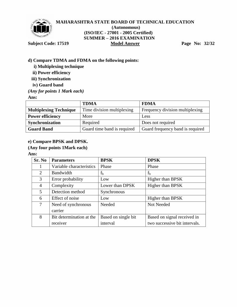
d) Compare TDMA and FDMA on the following points:
i) Multiplexing technique
ii) Power efficiency
iii) Synchronization
iv) Guard band
(Any for points 1 Mark each)
Ans:
TDMA FDMA
Multiplexing Technique Time division multiplexing Frequency division multiplexing
Power efficiency More Less
Synchronization Required Does not required
Guard Band Guard time band is required Guard frequency band is required
e) Compare BPSK and DPSK.
(Any four points 1Mark each)
Ans:
Sr. No Parameters BPSK DPSK
1 Variable characteristics Phase Phase
2 Bandwidth fb fb
3 Error probability Low Higher than BPSK
4 Complexity Lower than DPSK Higher than BPSK
5 Detection method Synchronous
6 Effect of noise Low Higher than BPSK
7 Need of synchronous
carrier
Needed Not Needed
8 Bit determination at the
receiver
Based on single bit
interval
Based on signal received in
two successive bit intervals.