Embed Size (px)
Citation preview

Magnetized Bunched Beam ERL Cooler
Stephen Benson, Slava Derbenev, David Douglas, Fay Hannon, Andrew Hutton, Rui Li, Bob Rimmer, Yves
Roblin, Chris Tennant, Haipeng Wang, He Zhang, Yuhong Zhang
EIC Accelerator Collaboration Meeting 2017October 10-12, 2017
Brookhaven National Lab, Upton NY
EIC Collaboration Meeting, October 10-12, 2017 1
Outline
• Bunched beam Cooler design specifications
• Cooling partition issue
• ERL (weak cooling) simulations
• CCR (strong cooling) design issues.
• Injection/extraction scheme
• Injector design
• Summary (future work)
EIC Collaboration Meeting, October 10-12, 2017 2

Baseline Design is Cooling Ring Fed by ERL• Same-cell energy recovery in 952.6 MHz SRF cavities• Uses harmonic kicker to inject and extract from CCR (divide by 11)• Assumes high charge, low rep-rate injector (w/ subharmonic acceleration
and bunching)• Use magnetization flips to compensate ion spin effects
ion beamion beam magnetization flip
top ring: CCR
bottom ring: ERL
injectorbeam dump linacfast extraction kicker fast injection kicker
De-chirper Re-chirper
circulating bunchesseptum
vertical bend
magnetization flipB < 0 B < 0B > 0B > 0
septum
EIC Collaboration Meeting, October 10-12, 2017 3
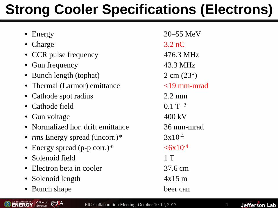
Strong Cooler Specifications (Electrons)• Energy 20–55 MeV • Charge 3.2 nC• CCR pulse frequency 476.3 MHz• Gun frequency 43.3 MHz• Bunch length (tophat) 2 cm (23°)• Thermal (Larmor) emittance <19 mm-mrad • Cathode spot radius 2.2 mm• Cathode field 0.1 T 3• Gun voltage 400 kV• Normalized hor. drift emittance 36 mm-mrad• rms Energy spread (uncorr.)* 3x10⁻⁴
• Energy spread (p-p corr.)* <6x10⁻⁴
• Solenoid field 1 T• Electron beta in cooler 37.6 cm• Solenoid length 4x15 m• Bunch shape beer can
EIC Collaboration Meeting, October 10-12, 2017 4

Cooler Specifications (protons)Case 1 – 63.3 GeV center of mass energy• Energy 100 GeV• Particles/bunch 2.0x10¹⁰
• Repetition rate 158.77 MHz• Bunch length (rms) 2.5 cm• Normalized emittance (x/y) 1.2/0.6 mm-mrad• Betatron function in cooler 100 m (at point between solenoids)Case 2 – 44.7 GeV center of mass energy• Energy 100 GeV• Particles/bunch 6.6x10⁹
• Repetition rate 476.3 MHz• Bunch length (rms) 1.0 cm• Normalized emittance (x/y) 1.0/0.5 mm-mrad• Betatron function in cooler 100 m (at point between solenoids)Ion ring lattice may be coupled or dispersed in solenoid. Ion beam may be partially offset from the electron beam.
EIC Collaboration Meeting, October 10-12, 2017 5

Need to Match Cooling Rate with IBSProton beam (CM energy 63.5 GeV)
Units x y z
Cooling rate 10-3 1/s -0.431 -1.434 -1.605
IBS rate 10-3 1/s 3.192 0.102 0.618
Total rate 10-3 1/s 2.761 -1.332 -0.987
Electron beam 3.2 nC
In horizontal direction, cooling is about one order weaker than IBS. To find equilibrium:• Apply dispersion at cooler to transfer longitudinal cooling to transverse directions• Apply transverse coupling to transverse horizontal IBS to vertical direction• Increase proton beam emittance• Decrease proton bunch charge
EIC Collaboration Meeting, October 10-12, 2017 6
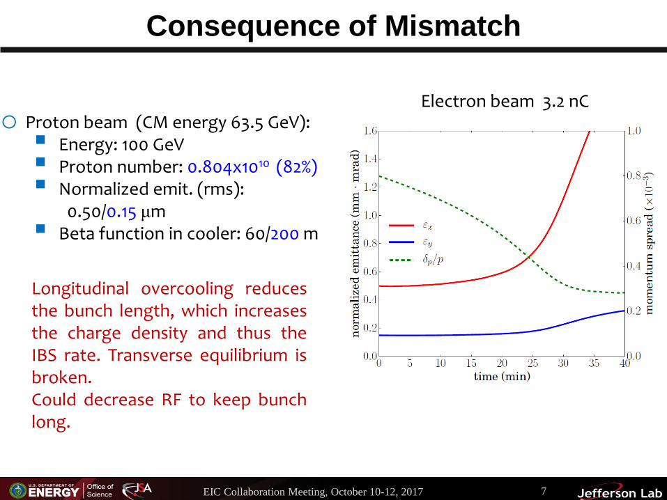
Consequence of Mismatch
o Proton beam (CM energy 63.5 GeV): Energy: 100 GeV Proton number: 0.804x10¹⁰ (82%) Normalized emit. (rms):
0.50/0.15 μm Beta function in cooler: 60/200 m
Electron beam 3.2 nC
Longitudinal overcooling reducesthe bunch length, which increasesthe charge density and thus theIBS rate. Transverse equilibrium isbroken.Could decrease RF to keep bunchlong.
EIC Collaboration Meeting, October 10-12, 2017 7
Cooling Simulations (See He Zhang’s talk)
A few main issues:
• Working in a new parameter regime. Can we trust
Betacool?
• Fixing the partition problem.
• Benchmarking the code. Some progress with IMP
measurements.
EIC Collaboration Meeting, October 10-12, 2017 8
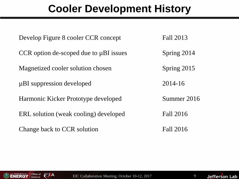
Cooler Development History
Develop Figure 8 cooler CCR concept Fall 2013
CCR option de-scoped due to µBI issues Spring 2014
Magnetized cooler solution chosen Spring 2015
µBI suppression developed 2014-16
Harmonic Kicker Prototype developed Summer 2016
ERL solution (weak cooling) developed Fall 2016
Change back to CCR solution Fall 2016
EIC Collaboration Meeting, October 10-12, 2017 9

Weak Cooler Specifications (Electrons)• Energy 20–55 MeV • Charge 420 pC• Gun frequency 476.3 MHz• Bunch length (tophat) 2 cm (23°)• Thermal emittance <19 mm-mrad • Cathode spot radius 2.2 mm• Cathode field 0.1 T 3• Gun voltage 400 kV• Normalized hor. drift emittance 36 mm-mrad• rms Energy spread (uncorr.)* 3x10⁻⁴
• Energy spread (p-p corr.)* <6x10⁻⁴
• Solenoid field 1 T• Electron beta in cooler 37.6 cm• Solenoid length 4x15 m• Bunch shape beer can
EIC Collaboration Meeting, October 10-12, 2017 10

ERL (Weak cooling) Design Status
• Injector output is 420 pC at 476.3 MHz• All transport is locally symmetric• Have completed S2E and I2E simulations for ERL design• Would eventually want to use two helicity exchanges and four solenoids.• Have not yet included the cooling leg merger and demerger.• I2E looks good but we have not been able to produce the initial distribution
from injector simulations.
Start of Injector-to-End (I2E) simulations
EIC Collaboration Meeting, October 10-12, 2017 11

Transverse behavior in ERL (I2E)
• Start with ideal distribution at booster exit (above).
• Find rms beam size vs. distance without (top) and with (bottom) CSR
• No re-optimization performed with CSR.
EIC Collaboration Meeting, October 10-12, 2017 12

Larmor emittance vs. Distance
Location I2E420 pC
I2E420 pC + CSR
S2E420 pC
Ideal2 nC
Initial Distribution 2.0 2.0 2.0 2.0
Merger Exit 3.01 7.24 2.72 15.96
Linac Exit 2.87 7.09 2.79 23.59
Arc 1 Exit 3.03 7.32 2.80 22.42
Solenoid Entrance 3.02 7.26 2.76 22.45
Arc 2 Exit 3.46 6.60 3.98 22.19
Linac Exit 4.44 7.79 4.06 22.92
Big challenge: preserving the emittance in the injector merger.
EIC Collaboration Meeting, October 10-12, 2017 13

Merger Options
We are looking at several ideas for mergers:• Penner Bend• Double bend achromat• W-bend• Chicane• Double barrel linac cavities• RF separator based merger• Off axis injectionEach of these has advantages and disadvantages. We are exploring both to find the best solution.
EIC Collaboration Meeting, October 10-12, 2017 14

Longitudinal Distribution at Cooling Solenoid
420 pC I2E
420 pCS2E
420 pC I2Ew/CSR
2 nCI2E
EIC Collaboration Meeting, October 10-12, 2017 15

S2E beam after Booster
EIC Collaboration Meeting, October 10-12, 2017 16

Harmonic Kicker (H. Wang)
• Harmonic Beam Kicker. A first 952.6 MHz copper cavity has been prototyped, bench measured, and satisfies beam dynamic requirements for a Circular Cooler Ring design for the bunched electron cooler.
EIC Collaboration Meeting, October 10-12, 2017 17

Challenges in the Strong Cooling Design
• Increased charge enhances space charge and CSR forces, but long pulse raises the possibility of shielding.
• Locally symmetric arcs are difficult at 55 MeV Globally symmetric arcs can work but must be tested one-by-one.
• Need tools for simulating the system. Want CSR, LSC, and shielding.
• Beams are big and halo creation and loss will be a problem.
B < 0 B < 0B > 0B > 0
EIC Collaboration Meeting, October 10-12, 2017 18
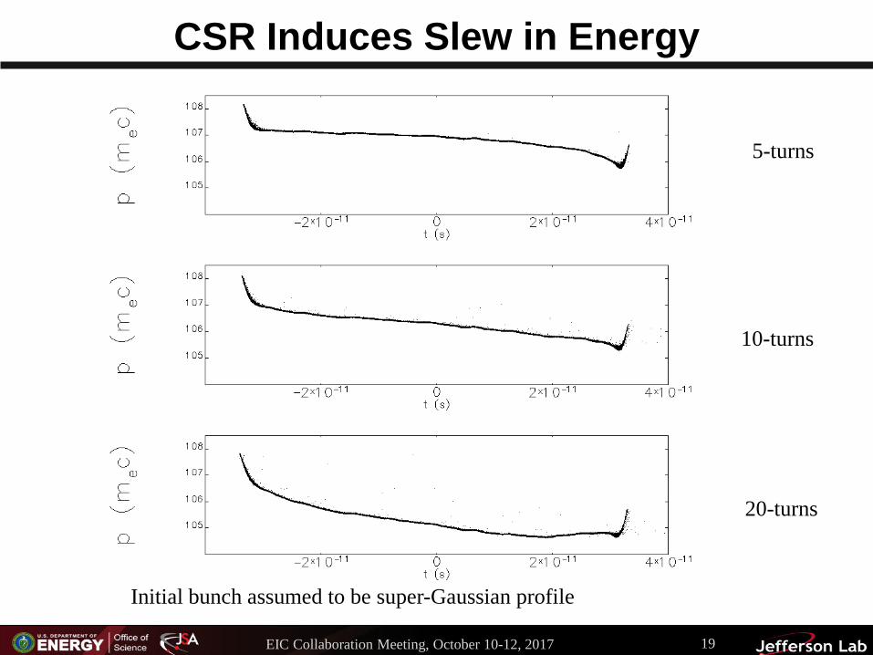
CSR Induces Slew in Energy
5-turns
10-turns
20-turns
Initial bunch assumed to be super-Gaussian profile
EIC Collaboration Meeting, October 10-12, 2017 19

after 20 turnsinitial
Correct Slew with RF cavity
Use RF cavity to remove chirp and reaccelerate the beam.
EIC Collaboration Meeting, October 10-12, 2017 20

Microbunching Gain using C.Y. Tsai Code• µBI gain is ≤ unity• needs to be less than unity for multiple passes (gain grows
exponentially)
EIC Collaboration Meeting, October 10-12, 2017 21

Exchange Region Layout
• CCR back leg
• ERL to CCR
EIC Collaboration Meeting, October 10-12, 2017 22

DIMAD Simulations After 11 Passes Through Exchange
• No CSR• No Space
charge
• All 6D Phase space projections shown
• Hourglass shape due to Chromaticity
• No large deformations in phase space after 11 passes.
EIC Collaboration Meeting, October 10-12, 2017 23

Magnetized Source (see Mamun’s talk)
• Magnetized Source for e-cooler at 32 mA: A high charge (420 pC) magnetized source is funded by the Jefferson Lab LDRD program that should operate up to 32 mA average current. This project concludes in 2018.
Magnetized beam parameters:• 𝑎𝑎0 = 1 – 5 mm, Bz = 0 – 2 kG • Bunch charge: 1 – 500 pC• Frequency: 15 Hz – 476.3 MHz• Bunch length: 10 – 100 ps• Average beam currents up to 32
mA• Gun high voltage: 200 – 350 kV
EIC Collaboration Meeting, October 10-12, 2017 24
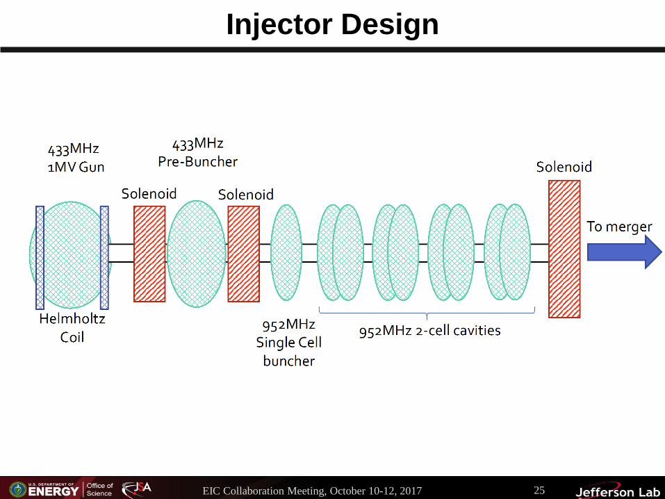
Injector Design
EIC Collaboration Meeting, October 10-12, 2017 25
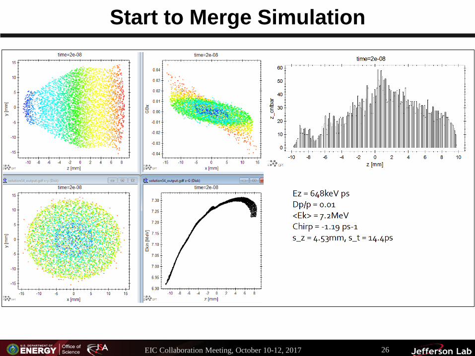
Start to Merge Simulation
EIC Collaboration Meeting, October 10-12, 2017 26
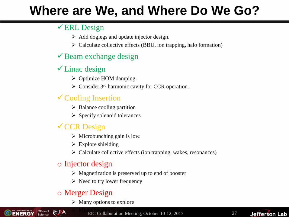
Where are We, and Where Do We Go?ERL Design
Add doglegs and update injector design. Calculate collective effects (BBU, ion trapping, halo formation)
Beam exchange designLinac design
Optimize HOM damping. Consider 3rd harmonic cavity for CCR operation.
Cooling Insertion Balance cooling partition Specify solenoid tolerances
CCR Design Microbunching gain is low. Explore shielding Calculate collective effects (ion trapping, wakes, resonances)
o Injector design Magnetization is preserved up to end of booster Need to try lower frequency
o Merger Design Many options to explore Might be able to just go straight in (straight merger).EIC Collaboration Meeting, October 10-12, 2017 27

Thank you!
EIC Collaboration Meeting, October 10-12, 2017 28
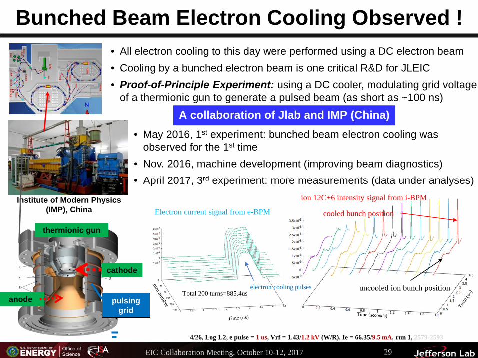
Bunched Beam Electron Cooling Observed !
Institute of Modern Physics (IMP), China
A collaboration of Jlab and IMP (China)
thermionic gun
cathode
anode pulsing grid
• All electron cooling to this day were performed using a DC electron beam• Cooling by a bunched electron beam is one critical R&D for JLEIC• Proof-of-Principle Experiment: using a DC cooler, modulating grid voltage
of a thermionic gun to generate a pulsed beam (as short as ~100 ns)
• May 2016, 1st experiment: bunched beam electron cooling was observed for the 1st time
• Nov. 2016, machine development (improving beam diagnostics) • April 2017, 3rd experiment: more measurements (data under analyses)
4/26, Log 1.2, e pulse = 1 us, Vrf = 1.43/1.2 kV (W/R), Ie = 66.35/9.5 mA, run 1, 2579-2593
ion 12C+6 intensity signal from i-BPM
Electron current signal from e-BPM
Total 200 turns=885.4uselectron cooling pulses uncooled ion bunch position
cooled bunch position
EIC Collaboration Meeting, October 10-12, 2017 29
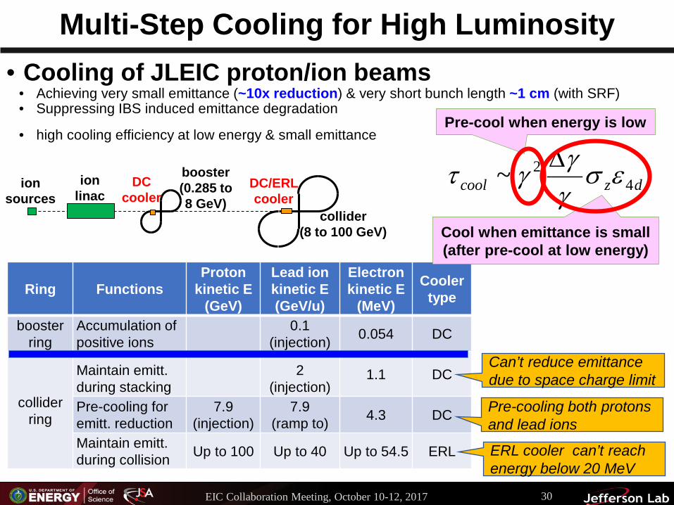
Multi-Step Cooling for High Luminosity• Cooling of JLEIC proton/ion beams
• Achieving very small emittance (~10x reduction) & very short bunch length ~1 cm (with SRF)• Suppressing IBS induced emittance degradation
• high cooling efficiency at low energy & small emittance
dzcool 42~ εσγγγτ ∆
Ring FunctionsProton
kinetic E (GeV)
Lead ionkinetic E (GeV/u)
Electron kinetic E
(MeV)
Cooler type
booster ring
Accumulation of positive ions
0.1(injection) 0.054 DC
collider ring
Maintain emitt. during stacking
2 (injection)
1.1 DC
Pre-cooling for emitt. reduction
7.9 (injection)
7.9 (ramp to) 4.3 DC
Maintain emitt. during collision Up to 100 Up to 40 Up to 54.5 ERL
Pre-cool when energy is low
Cool when emittance is small(after pre-cool at low energy)
ion sources
ion linac
booster (0.285 to 8 GeV)
collider(8 to 100 GeV)
DC/ERL cooler
DC cooler
Can’t reduce emittance due to space charge limit
ERL cooler can’t reach energy below 20 MeV
Pre-cooling both protons and lead ions
EIC Collaboration Meeting, October 10-12, 2017 30

Possible Merger Option
Septum Magnet
RF Separator with Superposed Magnetic Field
ERL Cryomodule
Injected Beam
Injector Cryomodule
• Use an RF Separator to separate the injected beam from the recirculating beam• Immerse the RF Separator in a DC magnetic field • Arrange timing and relative amplitudes so that the injected beam is not deflected
– Bunches are at maximum of RF deflection – bunch center has zero slope• This means that the kick seen by the recirculated beam is doubled• Needs to be sufficient to provide adequate separation at the septum
EIC Collaboration Meeting, October 10-12, 2017 31
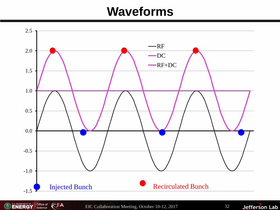
Waveforms
-1.5
-1.0
-0.5
0.0
0.5
1.0
1.5
2.0
2.5
RFDCRF+DC
Injected Bunch Recirculated Bunch
EIC Collaboration Meeting, October 10-12, 2017 32

Longitudinal Match
• Use longitudinal match developed for ERL-based cooler (C. Tennant et al., JLAB-TN in preparation)
• off-crest acceleration bunch of modest length• induce chirp for downstream bunching• bunch long enough to mitigate space charge, short enough to stay
within linac phase acceptance• debunch, dechirp during transport to cooling system• rechirp, compress during return transport for energy recovery• recover bunch of modest length with energy compression of chirp• Simply replace “ERL cooling system” with CCR• Invokes isochronous transport, avoids bunch length modulation
in CCR• Mitigate µBI
• Requires transfer of long bunch• Must be observant of kicker (non)linearity…
EIC Collaboration Meeting, October 10-12, 2017 33
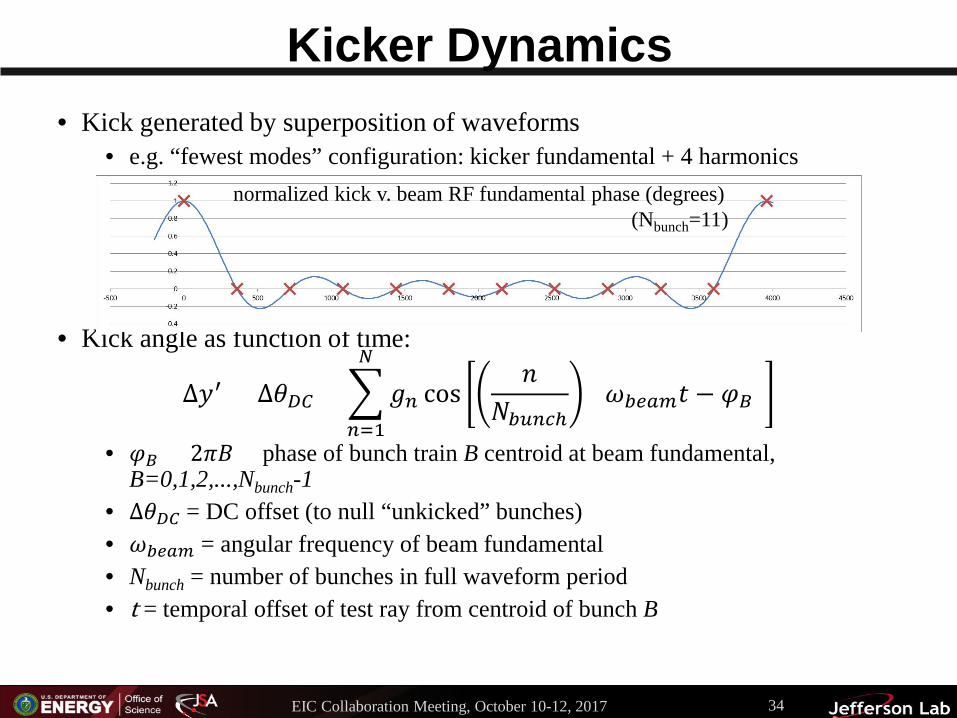
Kicker Dynamics• Kick generated by superposition of waveforms
• e.g. “fewest modes” configuration: kicker fundamental + 4 harmonics
• Kick angle as function of time:
∆𝑦𝑦′ = Δ𝜃𝜃𝐷𝐷𝐷𝐷 + �𝑛𝑛=1
𝑁𝑁
𝑔𝑔𝑛𝑛 cos𝑛𝑛
𝑁𝑁𝑏𝑏𝑏𝑏𝑛𝑛𝑏𝑏𝑏(𝜔𝜔𝑏𝑏𝑏𝑏𝑏𝑏𝑏𝑏𝑡𝑡 − 𝜑𝜑𝐵𝐵)
• 𝜑𝜑𝐵𝐵 = 2𝜋𝜋𝜋𝜋 = phase of bunch train B centroid at beam fundamental, B=0,1,2,...,Nbunch-1
• Δ𝜃𝜃𝐷𝐷𝐷𝐷 = DC offset (to null “unkicked” bunches)• 𝜔𝜔𝑏𝑏𝑏𝑏𝑏𝑏𝑏𝑏 = angular frequency of beam fundamental• Nbunch = number of bunches in full waveform period• t = temporal offset of test ray from centroid of bunch B
normalized kick v. beam RF fundamental phase (degrees) (Nbunch=11)
EIC Collaboration Meeting, October 10-12, 2017 34

From Schematic To Design
• “Match” 8 quad telescope• There is are 2 additional matches in the ERL
• Present optimization adds a wavelength here and there…• between PREK and vertical step up
• gives ½-wave transform PREK to IK (~¼ wave PREK to S)• between vertical step down and PSTK
• gives ½-wave transform EK to PSTK (~¼ wave S to PSTK)
• Layout:
Use figures from tech note.
EIC Collaboration Meeting, October 10-12, 2017 35
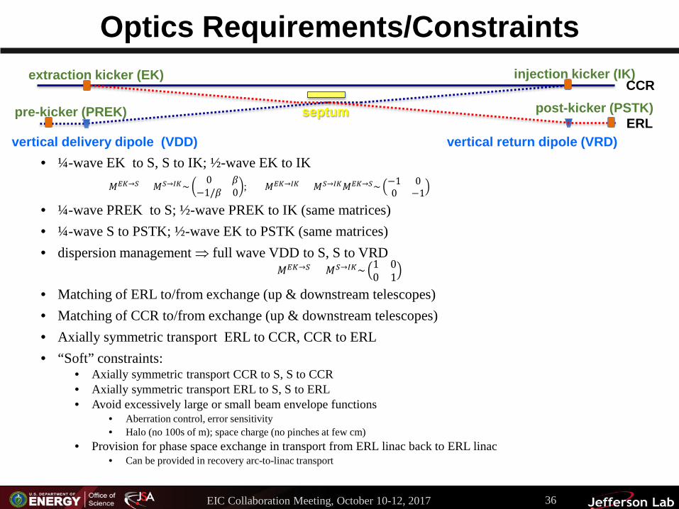
Optics Requirements/Constraints
• ¼-wave EK to S, S to IK; ½-wave EK to IK𝑀𝑀𝐸𝐸𝐸𝐸→𝑆𝑆 = 𝑀𝑀𝑆𝑆→𝐼𝐼𝐸𝐸~ 0 𝛽𝛽
−1/𝛽𝛽 0 ; 𝑀𝑀𝐸𝐸𝐸𝐸→𝐼𝐼𝐸𝐸 = 𝑀𝑀𝑆𝑆→𝐼𝐼𝐸𝐸𝑀𝑀𝐸𝐸𝐸𝐸→𝑆𝑆~ −1 00 −1
• ¼-wave PREK to S; ½-wave PREK to IK (same matrices)• ¼-wave S to PSTK; ½-wave EK to PSTK (same matrices)• dispersion management ⇒ full wave VDD to S, S to VRD
𝑀𝑀𝐸𝐸𝐸𝐸→𝑆𝑆 = 𝑀𝑀𝑆𝑆→𝐼𝐼𝐸𝐸~ 1 00 1
• Matching of ERL to/from exchange (up & downstream telescopes)• Matching of CCR to/from exchange (up & downstream telescopes)• Axially symmetric transport ERL to CCR, CCR to ERL• “Soft” constraints:
• Axially symmetric transport CCR to S, S to CCR• Axially symmetric transport ERL to S, S to ERL• Avoid excessively large or small beam envelope functions
• Aberration control, error sensitivity• Halo (no 100s of m); space charge (no pinches at few cm)
• Provision for phase space exchange in transport from ERL linac back to ERL linac• Can be provided in recovery arc-to-linac transport
CCR
ERL
extraction kicker (EK) injection kicker (IK)
septum
vertical delivery dipole (VDD) vertical return dipole (VRD)
post-kicker (PSTK)pre-kicker (PREK)
EIC Collaboration Meeting, October 10-12, 2017 36


![Retroflex versus bunched [r] in compensation for ...linguistics.berkeley.edu/phonlab/documents/2011/retrobunch_paper.pdf · Retroflex versus bunched [r] in compensation for coarticulation](https://img.dokumen.tips/doc/110x75/5b09bbee7f8b9a992a8e2cb3/retroflex-versus-bunched-r-in-compensation-for-versus-bunched-r-in-compensation.jpg)