Embed Size (px)
Citation preview
Magnetic levitation as a suspension mechanism for
cryogenic storage of hydrogen
Raymond Homan
Dissertation in partial fulfilment of the requirements for the degree
Master of Engineering at the North-West University, Potchefstroom
Campus
Supervisor: Professor Johan Markgraaff
December 2012

I
Acknowledgements
I would like to thank Professor Markgraaff for his guidance and contributions during this
study. His knowledge and experience is of great value to any student. I also thank my
parents, family and friends for their support and encouragement. I thank the North-West
University for all resources allocated to me to make the completion of this study possible.
I also thank God the Father of our Lord Jesus Christ for His unfailing strength and love and
for blessing me with the opportunity to further my studies as an engineer.
“For I am persuaded, that neither death, nor life, nor angels, nor principalities, nor powers,
nor things present, nor things to come, nor height, nor depth, nor any other creature, shall
be able to separate us from the love of God, which is in Christ Jesus our Lord.” Romans
8:38-39 King James Version Bible

II
Abstract
Current physical supports used in cryogenic storage vessels, in which liquid hydrogen is
stored, conduct heat from the environment to the liquid hydrogen which causes the hydrogen
temperature to rise and ultimately leads to hydrogen losses due to boil-off.
The focus of this study is to investigate magnetic levitation as a possible suspension
mechanism, eliminating the use of current physical supports and so doing reducing
hydrogen losses due to boil-off.
A conceptual design of a container which makes use of magnetic suspension is presented in
this study. The concept is validated on the basis of the forces obtainable between a
paramagnetic aluminium plate and an electromagnet, as well as the forces obtainable
between a neodymium magnet and a bulk Yttrium-Barium-Copper-Oxide superconductor.
The forces between the paramagnetic aluminium plate and electromagnet were determined
mathematically and tested experimentally. The forces between the magnet and
superconductor were determined mathematically and by finite element modelling and
simulations using ANSYS Multiphysics. The results obtained in the mathematical- and finite
element studies were then validated experimentally.
It was found that the forces obtained experimentally between the aluminium plate and
electromagnets are inadequate for magnetic suspension of the inner vessel given in the
conceptual design. It was also found that the forces obtained experimentally and in the
simulation studies for the magnet and superconductor of this study were inadequate due to
shortcomings in the magnet and superconductor obtained for experimental tests.
The conclusion of this study is that electromagnetic levitation should not be used as a
magnetic suspension mechanism for storage of liquid hydrogen. It is also concluded that
superconducting levitation can not be used as a suspension mechanism for the concept
presented in this study, unless the methods suggested to increase the levitation forces
between the neodymium magnet and superconductor are executed.
Keywords: Cryogenics, Hydrogen storage, Magnetic suspension, Superconducting
levitation.

III
Index
Index .................................................................................................................................... III
List of figures ........................................................................................................................ V
List of tables ....................................................................................................................... VIII
List of equations ................................................................................................................... IX
Chapter 1: Introduction ......................................................................................................... 1
1.1 Problem statement .................................................................................................. 9
1.2 Aim ......................................................................................................................... 9
Chapter 2: Literature Study ................................................................................................ 10
2.1 Background........................................................................................................... 10
2.1.1 Magnetism ..................................................................................................... 10
2.1.2 Superconductivity .......................................................................................... 13
2.1.3 Superconducting levitation fundamentals ....................................................... 15
2.1.4 Magnetic suspension ..................................................................................... 16
2.2 Research .............................................................................................................. 19
2.2.1 Superconducting levitation ............................................................................. 19
2.2.2 Modelling ....................................................................................................... 20
2.3 Summary .............................................................................................................. 26
2.4 Purpose of study ................................................................................................... 26
Chapter 3: Conceptual design ............................................................................................ 27
3.1 Outer vessel and connected parts ......................................................................... 28
3.1.1 Electromagnet ................................................................................................ 29
3.1.2 Outer vessel .................................................................................................. 29
3.1.3 Outer vessel support frame ............................................................................ 30
3.1.4 Permanent magnets....................................................................................... 31
3.1.5 Magnet caps .................................................................................................. 32
3.2 Inner vessel and internals ..................................................................................... 33

IV
3.2.1 Inner Vessel ................................................................................................... 33
3.2.2 Inner vessel support frame ............................................................................. 34
3.2.3 Superconductors ............................................................................................ 35
3.2.4 Superconductor cap ....................................................................................... 36
3.3 Magnetic suspension ............................................................................................ 36
3.3.1 Suspension mechanism ................................................................................. 37
3.3.2 Mathematical study ........................................................................................ 39
3.3.3 Finite element study ....................................................................................... 40
3.3.4 Summary ....................................................................................................... 44
Chapter 4: Concept validation ............................................................................................ 46
4.1 Electromagnetic suspension ................................................................................. 46
4.1.1 Experimental study ........................................................................................ 46
4.1.2 Discussion ..................................................................................................... 46
4.1.3 Conclusion and recommendations ................................................................. 47
4.2 Superconducting suspension ................................................................................ 48
4.2.1 Experimental study ........................................................................................ 48
4.2.2 Discussion ..................................................................................................... 52
4.2.3 Conclusion and recommendations ................................................................. 56
Chapter 5: Bibliography ...................................................................................................... 59
Appendix A: Cryogenic supports ........................................................................................ 63
Appendix B: Hydrogen vessel calculations ......................................................................... 66
Appendix C: Superconductor calculations .......................................................................... 69
Appendix D: Design drawings ............................................................................................ 70
V
List of figures
Figure 1: Diagram of hydrogen density at temperatures ranging from 20 K to 300 K for use
in cryogenic capable pressure vessels (Modified after Aceves, et al., 2009). ................. 2
Figure 2: Schematic of a double wall cryogenic tank according to US patent 4496073
showing the use of hot and so-called cold rings for inner container suspension and
insulation (Modified after Silver & Dehaas, 1985). ......................................................... 3
Figure 3: Schematic of a double wall cryogenic tank according to US patent 4680935
showing the use of a single connecting pipe for inner container suspension and
insulation (Modified after Murai, 1987). .......................................................................... 4
Figure 4: Schematic of a double wall cryogenic tank according to US patent 6708502
showing the use of insulated cross supports for inner container suspension and
insulation (Modified after Aceves, et al., 2004). ............................................................. 5
Figure 5: Schematic of cryogenic supports in which a strap and struts are illustrated
(Modified after Reed & Golda, 1997). ............................................................................ 5
Figure 6: Schematic of a double wall cryogenic tank showing the use of titanium wires as
supports for inner container suspension and insulation (Modified after van Vuuren, et
al., 2009). ...................................................................................................................... 7
Figure 7: Schematic illustration of the difference in inductance induced by electromagnets of
an electromagnet with a core and an electromagnet without a core in a vacuum or air
(Modified after Askeland & Phulé, 2003). .................................................................... 10
Figure 8: Two schematics which illustrate the basic characteristics of superconductors. The
effects on resistivity (left) and susceptibility (right) for superconductors are given as
functions of temperature (Modified after Fossheim & Sudboe, 2004)........................... 14
Figure 9: Schematic illustrating the field lines passing through a superconductor in the
normal state and field lines being expelled by the superconductor in the
superconducting state (Modified after Fossheim & Sudboe, 2004). ............................. 15
Figure 10: Schematic of an electromagnet inducing an eddy current in a paramagnetic plate
causing magnetic levitation of the electromagnet above the plate. .............................. 17
Figure 11: Schematic of magnetic field and superconductor interaction. The magnetic field
of the magnet is repelled by the superconductor and does not penetrate the
superconductor at all (Modified after Neves, et al., 2002). ........................................... 21
VI
Figure 12: Schematic of the superconductor ring and the magnetic dipole (μ) at angle θ for
which Fedda et al., (2007) derived the equations listed (Modified after Fedda et al.
2007). .......................................................................................................................... 25
Figure 13: Isometric view of a CAD model of the double wall cryogenic container concept for
liquid hydrogen storage in vehicular transport in which suspension of the inner vessel is
achieved by electromagnetic- and superconducting levitation. .................................... 28
Figure 14: CAD models of a section view and an isometric view of the electromagnet
mounted in its rack below the outer vessel centre. ...................................................... 29
Figure 15: Isometric view of a CAD model of the outer vessel and connected parts. .......... 30
Figure 16: Right sectioned view of the CAD model of the outer vessel support frame which
holds permanent magnets. .......................................................................................... 31
Figure 17: CAD models of an isometric view and a close up section view of a permanent
magnet mounted in a ring. ........................................................................................... 32
Figure 18: Sectioned isometric view of a CAD model of the permanent magnet cap. ......... 33
Figure 19: Isometric view of a CAD model of the inner vessel and internals. ...................... 34
Figure 20: Right sectioned view of the CAD model of the inner vessel support frame which
holds superconductors. ............................................................................................... 34
Figure 21: CAD models of an isometric view and a close up isometric view of a
superconductor mounted in a ring. .............................................................................. 35
Figure 22: Isometric view of a CAD model of the superconductor cap. ............................... 36
Figure 23: Close up frontal sectioned view of a CAD model of a superconductor and magnet
mounted their specific support frames within their specific containers with an air gap of
10 mm between the magnet and superconductor. ....................................................... 38
Figure 24: Graph of the relationship between levitation force and air gap obtained by
calculations. ................................................................................................................ 40
Figure 25: CAD model of the simulated permanent magnet at a levitation gap of 10 mm. .. 41
Figure 26: Graph for levitation forces acting on the superconductor, magnet and the sums of
forces at each air gap interval obtained from simulations. ........................................... 43
Figure 27: Graph for levitation forces measured in the mathematical- and finite element
study. .......................................................................................................................... 45

VII
Figure 28: Top section view of a CAD model for the concept wherein an air bag is used to
suspend the inner vessel while superconducting levitation is initiated. ........................ 47
Figure 29: Schematic of the experimental setup. For simplicity reasons the holder in which
the superconductor is cooled is not displayed in this schematic. ................................. 49
Figure 30: Schematic of the field lines of the neodymium magnet pinning in the YBCO
superconductor at an air gap of 10 mm. ...................................................................... 50
Figure 31: Photo of the neodymium magnet in its holder while pinned and levitating above
the YBCO superconductor which is in the superconducting state. ............................... 51
Figure 32: Graph of the two tests conducted for the forces measured between a magnet and
superconductor at specific air gap increments. ............................................................ 52
Figure 33: Graph of levitation force as a function of air gap, measured experimentally and
determined by calculation and simulation, between a neodymium magnet and a
superconductor. .......................................................................................................... 53
Figure 34: The graph for levitation forces acting on the superconductor, magnet and the
sums of forces as a function of air gap interval, obtained from simulations for the
measured magnetic properties of the magnet. ............................................................. 54
Figure 35: Graph of levitation forces between the superconductor and magnet as a function
of air gap interval obtained during experiments and simulations for the measured
magnetic properties of the magnet. ............................................................................. 55
Figure 36: Results obtained from solution of EES code given for calculation of required
hydrogen mass, storage volume, container size and magnet size. .............................. 68

VIII
List of tables
Table 1: Calculated forces between the magnet and superconductor for air gap intervals
from 0.1 mm to 10mm. ................................................................................................ 39
Table 2: Table for the forces determined in the simulation acting on the magnet and
superconductor and the sums of forces at each air gap interval. ................................. 44
Table 3: Table for the levitation forces determined between the magnet and superconductor
in the experimental study for Test 1 and Test 2. .......................................................... 51
Table 4: Table for the forces determined in the simulation acting on the magnet and
superconductor and the sums of forces as a function of air gap position for the
measured magnetic properties of the magnet. ............................................................. 55
Table 5: Results listed for calculations of heat flow through straps and tubes and hydrogen
boil off due to heat flow through supports. ................................................................... 65
Table 6: Results obtained for the solution of Equation 17 for the magnet and superconductor
of this study. ................................................................................................................ 69
Table 7: A list of design drawings and drawing numbers for a magnetically suspended
cryogenic container, which makes use of superconductor thin films suggested as a
result of this study. ...................................................................................................... 70

IX
List of equations
(1) ................................................................................................................. 10
(2) .............................................................................................................. 11
(3) .................................................................................................................. 11
(4) ............................................................................................................. 11
(5) ...................................................................................................... 11
(6) ............................................................................................................. 11
(7) .......................................................................................................... 11
(8) ............................................................................................... 14
. (9) ............................................................................................................. 14
(10) ................................................................................................. 14
(11) ................................................................................................. 14
(12) ............................................................................................ 17
(13) ........................................................................................................ 18
(14) .................................................................................................... 18
(15) ..................................................................................................... 23
(16) 25
(17) .......................................................................... 25
(18) ................................................................................ 25
1
Chapter 1: Introduction
Hydrogen may be an alternative fuel or energy carrier in the future as it is already
undergoing research as a fuel source for use in fuel cells (Ramachandran & Menon, 1998).
Hydrogen has to be combusted in oxygen to produce an exothermic reaction and release
energy. In nature hydrogen exists in compounds with other elements only, but can be freed
if hydrogen (H2) is required for use. Hydrogen can be produced from any primary energy
fuel like coal, oil and natural gas (Winter, 2009).
Hydrogen is used in numerous applications which include but is not limited to:
Petroleum processing: Hydrogen is used to hydrogenate sulphur (S) and nitrogen
(N) compounds to finally remove them as H2S and NH3 reducing NOx and SOx
emissions in petroleum processing (Ramachandran & Menon, 1998).
Petrochemical production: Hydrogen and carbon monoxide react over a catalyst at
high pressures and temperatures to form methanol (Ramachandran & Menon, 1998).
Fertilizer production: Ammonia, which is used in the production of fertilizer, is
produced from hydrogen and nitrogen (N2) (Ramachandran & Menon, 1998).
In the above mentioned applications and most areas where hydrogen is used, the need for
proper storage of hydrogen arises. Metal hydrides are being researched as a possible
storage medium (Sakintuna, et al., 2007). However, hydrogen is currently stored mainly in
gas form which is either compressed (cH2) or cryo-compressed (ccH2) and liquid form (L-H2).
Cryo-compressed hydrogen is hydrogen gas stored at high pressure and sub-critical
temperature for example at 38 MPa and 77 K (-196.15 °C).
Gaseous hydrogen is compressed and stored in cylinders. Filling times for these cylinders
have been successfully tested between 40 seconds and 6 minutes (Mérida & Dicken, 2007).
Although filling times of 40 seconds is possible, compressed hydrogen storage has
disadvantages which include leakage of hydrogen from storage cylinders and low volumetric
hydrogen storage density. Furthermore, the high mass and size of cylinders used for
storage of compressed hydrogen contributes to transport difficulties.
The first of two major disadvantages for liquid hydrogen storage is the high energy cost to
liquefy hydrogen. This is mainly due to the extremely low boiling point (approximately 20.3 K
or -252.9 °C) and high heat capacity of hydrogen. The second of these is the constant loss
of hydrogen during storage, because of heat transfer between the environment and the
hydrogen stored, which causes hydrogen boil-off (van Vuuren, et al., 2009).

2
Figure 1 is a diagram which shows the operating range of cryogenic pressure vessels for
hydrogen storage at temperatures ranging from 20 K (-253.15 °C) to 300 K (26.85 °C). This
diagram also shows the density of the hydrogen due to the pressure at which it is stored and
whether it is stored as a compressed gas or in liquid form.
For the diagram in Figure 1, the temperature scale is on the horizontal axis. Storage
pressure is represented by the dotted lines and hydrogen density is presented on the left
vertical axis. Solid lines represent the theoretical minimum work, which is the energy
required to produce hydrogen in either the gaseous or liquid phase. The green shaded
region represents the operating region of cryogenic pressure vessels for hydrogen storage
(Aceves, et al., 2009).
Figure 1: Diagram of hydrogen density at temperatures ranging from 20 K to 300 K for use in
cryogenic capable pressure vessels (Modified after Aceves, et al., 2009).
The conditions required to store hydrogen as a compressed gas at ambient temperature are
represented by the red dot in Figure 1. The volume occupied by 5 kg of compressed
gaseous hydrogen at 300 K (26.85 °C) and approximately 400 atm is 200 l. Work of
approximately 1.75 kWh/kg is required to produce cH2 at these specific conditions.
The conditions required to store hydrogen as a liquid are represented by the blue dot in
Figure 1. The volume occupied by 5 kg of L-H2 at 20 K (-253.15 °C) and approximately 200

3
atm is 70 l. Work of approximately 3.25 kWh/kg is required to produce L-H2 at these specific
conditions.
Hand calculations were used to confirm the approximate values read from Figure 1. The
storage volume required for 5 kg of cH2 was calculated at approximately 213 l. The cH2 has
a relatively low density of 23.44 kg/m3 compared to L-H2 which is much more compact and
has a higher density of approximately 71.26 kg/m3.
The difference in density implies that approximately 70 l is required to store 5 kg L-H2
compared to the 213 l required to store 5 kg cH2 (Aceves, et al., 2009). A saving of 143 l in
storage volume is achieved if 5 kg H2 is stored in liquid form.
According to the USDOE (United States Department of Energy) hydrogen-powered vehicles
should travel more than 300 miles (approximately 480 km) between fills to compete with
petrol and diesel powered vehicles (Energy, 2011).
If hydrogen losses are ignored, calculations show that a car with an engine size of 118 kW
requires approximately 14 kg hydrogen to travel 480 km. If L-H2 is to be used, only 200 l
storage volume is required compared to 600 l for cH2, which is paramount for vehicular
transport applications although this advantage comes with a cost penalty associated with the
liquefaction energy requirement.
Different designs and patents for L-H2 storage and transportation exist. Figure 2 is a
schematic of a section view of US patent 4496073 which was filed for storage of cryogenic
liquids (Silver & Dehaas, 1985).
Figure 2: Schematic of a double wall cryogenic tank according to US patent 4496073 showing
the use of hot and so-called cold rings for inner container suspension and insulation (Modified
after Silver & Dehaas, 1985).
4
The container consists of an outer container, inner container, a support tube and support
rings. By using the support tube and support rings the inner container is supported within
the outer container minimizing conduction paths between the containers and environment.
The empty space between the containers and the support tube is filled with proper insulation
of which multilayer insulation is an example. The space between the two containers is then
gas evacuated (Silver & Dehaas, 1985).
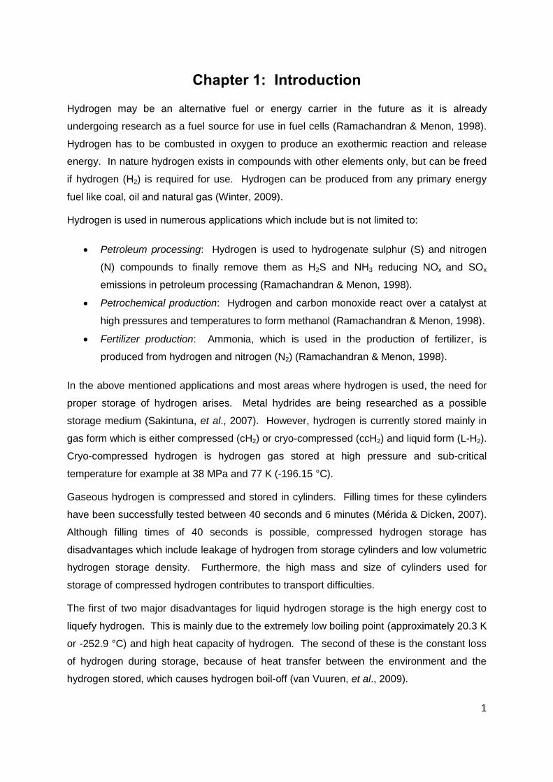
A schematic depiction of US patent 4680935 which was filed by Murai (1987) for the storage
of cryogenic liquids is presented in Figure 3. The tank consists of an inner container
suspended within an outer container by a single connecting pipe. The connecting pipe
minimizes the heat transfer from the environment by limiting conduction to the neck of the
pipe only.
Additionally, a vacuum is created in the space between the two containers to minimize
convection from the outer container at ambient temperature and the inner container at
cryogenic temperature. Any radiation effects are countered by shields placed between the
containers (Murai, 1987).
Figure 3: Schematic of a double wall cryogenic tank according to US patent 4680935 showing
the use of a single connecting pipe for inner container suspension and insulation (Modified
after Murai, 1987).
Presented in Figure 4, is a schematic depiction of a section view of US patent 6708502 filed
for the storage of cryogenic fluids (Aceves, et al., 2004). This container consists of an inner

5
pressure vessel supported within an outer pressure vessel by means of insulated cross
supports, to reduce heat transfer and reduce boil-off.
Figure 4: Schematic of a double wall cryogenic tank according to US patent 6708502 showing
the use of insulated cross supports for inner container suspension and insulation (Modified
after Aceves, et al., 2004).
Although the cryogen is stored in the inner container and thermal insulation is provided
between the two containers in Figure 4, heat transfer still occurs from the environment to the
inner container through these essential supports (Aceves, et al., 2004).
To further limit heat transfer through the required supports many cryogenic container
designs make use of supports made from composites due to their low thermal conductivity at
low temperatures (Reed & Golda, 1997). Composite supports include straps under tensile
forces and struts under compressive forces. Figure 5 is a schematic presentation of a strap
and different types of tubes.
Figure 5: Schematic of cryogenic supports in which a strap and struts are illustrated (Modified
after Reed & Golda, 1997).

6
An example of support struts that was mentioned earlier is the cross supports of US patent
6708502 in Figure 4. These support types are fibre reinforced and traditionally epoxy-based
composites (Reed & Golda, 1997).
For cryogenic containers that use straps as supports, between six and eight straps are used
to balance the applied forces that are found between the warm and cold structures of the
cryogenic containers. To combat thermal influences between these structures, support
straps are made as long and thin as possible to maximise the thermal path (Reed & Golda,
1997).
Alumina and glass fibres (such as E- and S-glass) are examples of the different fibres used
to reinforce straps. As mentioned earlier straps may be epoxy-based or reinforced with
PEEK (polyetheretherketone), a type of resin matrix (Reed & Golda, 1997).
For a container setup in which L-H2 (20 K or -253.15 °C) is stored of which one container is
kept within another such as in Figure 2 and Figure 4 the temperature gradient between the
outer container (ambient temperature 300 K or 26.85 °C) and the inner container is 280 K.
Due to the fact that heat flows from warmer regions to colder regions, a temperature rise for
the cryogen takes place due to the addition of heat through the supports mentioned. This
rise in temperature in turn causes boil-off of the L-H2.
Calculations of heat transfer and the effects thereof were carried out for a double wall
cryogenic container for which an inner container is suspended within an outer container with
the use of carbon fibre straps. Conductivity values for carbon fibre supports given by Reed
and Golda (1997) were used for this calculation.
Heat transfer through one carbon strap was calculated at 7.2 mW which results in a
calculated hydrogen loss of approximately of 1.4 g/day due to boil-off. For six straps the
total heat transfer through the straps is 43.2 mW, resulting in hydrogen boil-off of 8.4 g/day.
The calculations and results for heat transfer through carbon straps are discussed in
Appendix A.
Tubes (also called struts) are also used as supports in cryogenic containers. Tubes are built
to have minimal thickness and are usually hollow cylinders to minimize the heat transfer
area, reducing heat transfer to the cryogen in the container (Reed & Golda, 1997).
Calculations for the heat transfer through E-glass support tubes were conducted for a design
similar to that in Figure 4 in which a double wall cryogenic container makes use of E-glass
tubes to suspend an inner container within an outer container.
7
One tube has a calculated heat transfer of approximately 5.7 mW, which corresponds to a
hydrogen loss of approximately 1.1 g/day due to boil-off. For six struts, the heat transfer was
calculated at approximately 34 mW which results in a hydrogen loss of approximately 6.6
g/day due to boil-off. The calculations and results for heat transfer through E-glass tubes
are discussed in Appendix A.
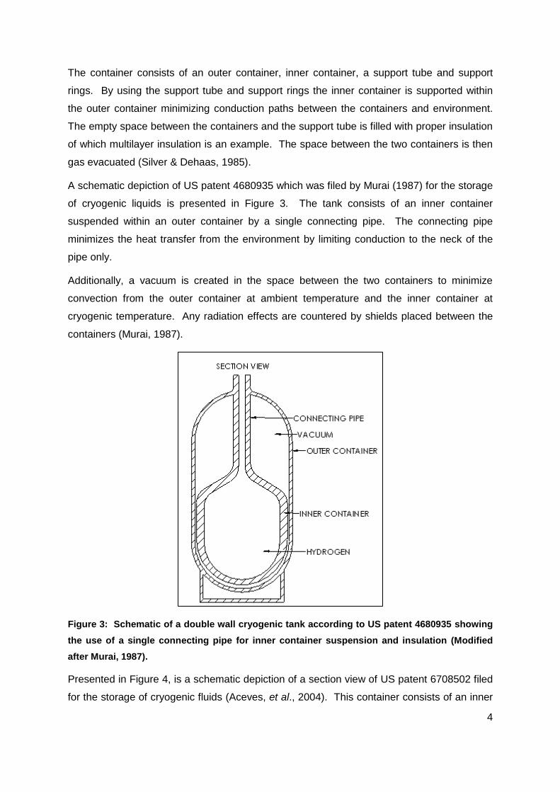
Van Vuuren, et al. (2009) suggested a concept (depicted in Figure 6) for the cryogenic
storage of hydrogen in vehicles and other transport systems that may adhere to the USDOE
requirements. In Figure 6, the inner container, which contains ccH2, is contained within an
outer container. Van Vuuren, et al. (2009) proposed to use titanium wires (instead of other
structured material supports) to support the inner container within the outer container to
minimize conduction to the inner container.
The suggested cross sectional area of a wire to achieve a heat transfer of maximum 0.5 W is
3.56 mm2. If six wires are used to stabilize the inner container in the different axes and the
effects of MLVSI and the nitrogen are ignored, the heat transfer to the hydrogen container is
3 W (van Vuuren, et al., 2009).
Figure 6: Schematic of a double wall cryogenic tank showing the use of titanium wires as
supports for inner container suspension and insulation (Modified after van Vuuren, et al.,
2009).
To further minimize heat flow to the inner vessel, Van Vuuren, et al. (2009) proposed to
thermally insulate the outer vessel with MLVSI (multi-layer vacuum super insulation) and by
filling the outer container with L-N2 (liquid nitrogen). The L-N2 absorbs heat that is
conducted from the environment through the vessel walls and wire supports which would
otherwise be absorbed by the hydrogen. The L-N2 is then boiled-off and due to the cooling
effect of evaporation, the hydrogen in the inner vessel is kept at 77 K (-196.15 °C).

8
Van Vuuren, et al. (2009) states that the heat flowing into the container, by means of
conduction through the wire supports, insulation and pipe neck can be limited to 2.5 W. For
this 2.5 W, a liquid nitrogen bleed-off rate of approximately 1 kg/day is required to keep the
hydrogen from increasing in pressure and temperature and ultimately having to be bled off
(van Vuuren, et al., 2009).
Once all the nitrogen has evaporated, the temperature of the hydrogen container will start to
rise which in turn causes a pressure increase in the hydrogen container. To then counter
the increase in pressure and keep the container at a safe operating pressure, hydrogen must
be bled-off. The initial hydrogen bleed-off rate is 160 g/day. This initial bleed rate will
increase with an increase in the hydrogen container’s temperature. The hydrogen
temperature will increase by 3.1 °C/day (van Vuuren, et al., 2009).
The advantage of this design is that a four day window exists wherein nitrogen can be
refilled before completely being evaporated, thus before the hydrogen is required to be bled
off. Compared to the container that makes use of struts (container using struts had less
calculated hydrogen losses than container using straps) the concept of Van Vuuren, et al.
(2009) will have 0 % hydrogen loss for the first four days, whereas the container using struts
will have lost 26.4 g H2 by the fourth day.
Although the concept suggested by Van Vuuren, et al. (2009) has the advantage of nitrogen
as thermal insulation which ensures a longer storage period without hydrogen loss, there is a
cost penalty due to the infrastructure required for nitrogen storage at hydrogen filling
stations.
In summary, methods which are used to reduce conduction of heat from the environment to
the cryogen include the use of nitrogen as a thermal insulator, drawing a vacuum between
the containers (van Vuuren, et al., 2009), physical supports such as support rings (Silver &
Dehaas, 1985), carbon and other fibre reinforced straps, E-glass tubes (Reed & Golda,
1997), titanium wires (van Vuuren, et al., 2009), insulated cross supports (Aceves, et al.,
2004) and thin connecting pipes (Murai, 1987).
Although all these schemes lower the thermal conduction from the outer container to the
inner container, there is still some level of conduction from the environment to the cryogen
through the above mentioned support methods that contributes to hydrogen losses due to
boil-off.

9
1.1 Problem statement
Heat from the environment is added to the cryogenic fluid in cryogenic containers, by means
of conduction through current support systems implemented in cryogenic containers. This
heat addition contributes to a temperature rise of the cryogen and ultimately leads to boil-off
resulting in unwanted losses of the fluid.
1.2 Aim
A possible method to further reduce the contribution of current support systems to hydrogen
boil-off is the use of magnetic suspension of the inner containers while eliminating any other
form of physical support. The aim of this study therefore, is to investigate the feasibility of
magnetic suspension for cryogenic containers.

10
Chapter 2: Literature Study
2.1 Background
2.1.1 Magnetism
All materials respond to magnetic fields, and it is suggested that there is no such thing as a
“nonmagnetic” material. However the response to magnetic fields is not the same for all
materials which leads to the conclusion that some materials are strongly magnetic while
others are weakly magnetic. Weak magnetic materials are usually referred to as
“nonmagnetic” materials (Askeland & Phulé, 2003).
The relationship between magnetic field, magnetization and permeability is explained using
a current passing through a wound coil as shown in Figure 7. A magnetic field is produced
when the electric current passes through the coil.
Figure 7: Schematic illustration of the difference in inductance induced by electromagnets of
an electromagnet with a core and an electromagnet without a core in a vacuum or air (Modified
after Askeland & Phulé, 2003).
The magnetic field strength H, measured in A/m, is then given by
(1)
where n is the number of turns, I is the current (A) and L is the length of the coil (m).
11
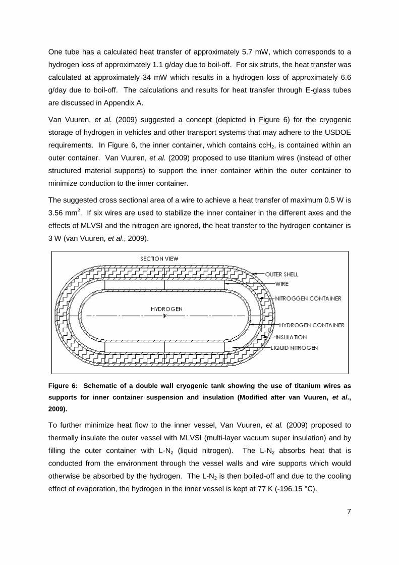
When the magnetic H-field is applied in a vacuum, magnetic flux lines are induced. The
number of flux lines called magnetic flux density or inductance is related to the H-field by
(2)
where B is the magnetic flux density or inductance measured in Tesla and µ0 is the
permeability constant for free space (in vacuum) 4π x 10-7 Henry/m (Askeland & Phulé,
2003).
When placing a material core in the magnetic field, the magnetic flux density is determined
by the interaction of the induced and permanent magnetic dipoles with the field. The flux
density is now given by
(3)
where µ is the permeability of the material in the field (Askeland & Phulé, 2003).
A greater number of flux lines which do more work are generated if the magnetic moments
reinforce the applied field. That is, if µ > µ0 there is a magnification of the magnetic field. If µ
< µ0, the magnetic moments oppose the field.
The relationship of µ to µ0 is called the relative permeability (µr). For a large relative
permeability the magnetic field is amplified by the material (Askeland & Phulé, 2003). This
relationship is given by
(4)
The H-field causes magnetization (M) of the core material which partially contributes to the
total flux density B. The equation for magnetic flux density is then rewritten as
(5)
where µ0H is the component of inductance caused by the applied field (H-field) and µ0M is
the component of inductance caused by the magnetic core material.
According to Askeland and Phulé (2003) the amplification produced by a material is given by
the relationship of magnetization to the applied field. This relationship is called the magnetic
susceptibility and is given by
(6)
As with µr, m also refers to the degree to which a material enhances the magnetic field
(Askeland & Phulé, 2003). The relationship between µr and m is given by
(7)

12
Different materials which differ in µr magnitude exhibit different magnetic behaviour.
Paramagnetic behaviour, ferromagnetic behaviour and diamagnetic behaviour are reviewed
in the following paragraphs.
Materials which have unpaired electrons have a net magnetic moment associated with each
atom due to electron spin. An applied magnetic field causes the dipoles to line up with the
field inducing a positive magnetization. There is no interaction between the dipoles and
therefore large forces are required to align all the dipoles. As soon as the magnetic field is
removed in these materials called paramagnetic materials, this effect is lost. (Askeland &
Phulé, 2003).
Paramagnetic materials have μ > μ0, and therefore they also have low µr values and low
positive m values. The magnitude for m of paramagnetic materials ranges from 10-4 to 10-5.
Paramagnetic materials include aluminium, titanium and alloys of copper (Askeland & Phulé,
2003).
Ferromagnetism is caused by the unfilled energy levels in the 3d level of iron, nickel and
cobalt. The permanent unpaired dipoles, effortlessly line up with the imposed magnetic field
due to the mutual reinforcement of the dipoles. Due to ferromagnetic materials having μ >>
μ0, they also have high µr values and high positive m values, and therefore ferromagnetic
materials are strong magnetic materials (Askeland & Phulé, 2003).
Large magnetizations are obtained even for small magnetic fields which deliver magnetic
susceptibilities of the order 106 (Askeland & Phulé, 2003). Rare earth magnets are
ferromagnetic and contain rare earth metals such as neodymium which is used for
neodymium (NdFeB) magnets. NdFeB magnets are often used for magnetic levitation
purposes in combination with superconductors.
Diamagnetic materials repel applied fields. When a magnetic field acts on an atom a
magnetic dipole is induced by the field over the atom. This field influences the magnetic
moment caused by the orbiting electrons. The magnetic field is then opposed by the dipoles
which cause the magnetization to be less than zero (Askeland & Phulé, 2003).
Diamagnetism gives a relative permeability of about 0.99995 which results in a negative
susceptibility (-0.00005). Diamagnetic materials have μ < μ0, causing them to have low µr
values and low negative m values. Copper, silver and gold are diamagnetic at room
temperature. Of importance however, is that superconductors display pure diamagnetic
behaviour ( m = -1, μr = 0) below their critical temperatures (Askeland & Phulé, 2003).

13
2.1.2 Superconductivity
Heike Kamerlingh Onnes discovered superconductors when he discovered
superconductivity in metals at very low temperatures (De Bruyn Ouboter, 1997). Research
has shown that some materials become superconducting at low temperatures such as lead
at 7.2 K (-265.95 °C), niobium at 8 K (-265.15 °C), niobium nitride at 15 K (-258.15 °C) and
niobium germanium at 23 K (-250.15 °C) (Jha, 1988). Such superconductors are referred to
as low temperature superconductors (LTSC).
High temperature superconductors (HTSC) are superconductors which become
superconducting at higher temperatures compared to LTSC that become superconducting at
extremely low temperatures.
Paul Chu discovered yttrium barium copper oxide (Y1Ba2Cu3Ox-7 or YBCO) an HTSC
compound which has a transition temperature of 90 K (-183.15 °C) (Jha, 1988). Other
HTSC materials also exist of which most are compounds of yttrium, bismuth or thallium such
as BiSrCaCuO that becomes superconducting at 110 K (-163.15 °C) and TlBaCaCuO at 125
K (-148.15 °C) (Jha, 1988).
Superconductivity has two very impressive and important properties. The first property is
that once a material is cooled below its Tc (superconducting transition temperature) it loses
all its resistivity making a transition from finite resistivity ρ to ρ = 0. In other words it
conducts direct current without resistance thus it’s conductivity becomes infinite (σ = ∞)
(Fossheim & Sudboe, 2004; Iwasa, 2009).
The second property is the change in magnetic susceptibility ( ) where above Tc the value
for is a small positive value, which causes the material to be paramagnetic, but below Tc it
becomes = -1, thus it is a perfect diamagnet (Askeland & Phulé, 2003; Fossheim &
Sudboe, 2004; Iwasa, 2009).
Meissner and Ochsenfeld discovered perfect diamagnetism (μr = 0) for a superconductor in
the superconducting state and observed that an applied magnetic field penetrates the
superconductor above its Tc (Fossheim & Sudboe, 2004).
However, as soon as the temperature drops below Tc the field is expelled from the
superconductor (Bleuler, et al., 2009; Fossheim & Sudboe, 2004). This means that the flux
density inside the superconductor becomes zero (B = 0) below Tc. This expelling of the
magnetic field from the superconductor is known as the Meissner effect.

14
Figure 8 presents the change in resistivity and susceptibility when the Meissner effect is
induced in a superconductor as the temperature changes from T > Tc to T < Tc (Fossheim &
Sudboe, 2004).
Figure 8: Two schematics which illustrate the basic characteristics of superconductors. The
effects on resistivity (left) and susceptibility (right) for superconductors are given as functions
of temperature (Modified after Fossheim & Sudboe, 2004).
For a magnetic body in the superconducting state, the magnetic flux density (Equation 5) is
set equal to zero, which results in
(8)
which in a superconductor gives,
. (9)
The substitution of Equation 9 into Equation 6 then gives a magnetic susceptibility of -1 as
presented by
(10)
Substituting Equation 10 into Equation 7 results in a zero relative permeability,
(11)
Both μr = 0 and = -1 are used to describe the Meissner effect (Fossheim & Sudboe, 2004).
When the superconductor’s temperature drops below Tc, shielding currents arise in the
superconductor surface and a field both inside and outside the superconductor is created.
The applied H-field and induced fields then cancel out exactly inside the superconductor,
while the fields on the outside add, giving rise to expulsion of the B-field from the
superconductor (Fossheim & Sudboe, 2004).
15
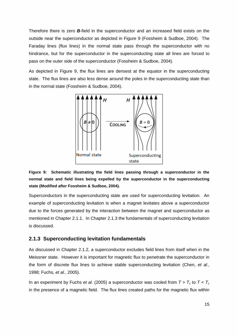
Therefore there is zero B-field in the superconductor and an increased field exists on the
outside near the superconductor as depicted in Figure 9 (Fossheim & Sudboe, 2004). The
Faraday lines (flux lines) in the normal state pass through the superconductor with no
hindrance, but for the superconductor in the superconducting state all lines are forced to
pass on the outer side of the superconductor (Fossheim & Sudboe, 2004).
As depicted in Figure 9, the flux lines are densest at the equator in the superconducting
state. The flux lines are also less dense around the poles in the superconducting state than
in the normal state (Fossheim & Sudboe, 2004).
Figure 9: Schematic illustrating the field lines passing through a superconductor in the
normal state and field lines being expelled by the superconductor in the superconducting
state (Modified after Fossheim & Sudboe, 2004).
Superconductors in the superconducting state are used for superconducting levitation. An
example of superconducting levitation is when a magnet levitates above a superconductor
due to the forces generated by the interaction between the magnet and superconductor as
mentioned in Chapter 2.1.1. In Chapter 2.1.3 the fundamentals of superconducting levitation
is discussed.
2.1.3 Superconducting levitation fundamentals
As discussed in Chapter 2.1.2, a superconductor excludes field lines from itself when in the
Meissner state. However it is important for magnetic flux to penetrate the superconductor in
the form of discrete flux lines to achieve stable superconducting levitation (Chen, et al.,
1998; Fuchs, et al., 2005).
In an experiment by Fuchs et al. (2005) a superconductor was cooled from T > Tc to T < Tc
in the presence of a magnetic field. The flux lines created paths for the magnetic flux within

16
the superconductor. This caused the field lines to be pinned in the superconductor and not
excluded as previously discussed for the Meissner effect. Cooling of the superconductor
from T > Tc to T < Tc within a magnetic field is called field cooling (Fuchs, et al., 2005).
In an experiment by Chen et al. (2007) a magnet was brought close enough to a
superconductor, after being zero-field cooled. The flux was forced through the
superconductor by the magnet and trapped in the superconductor causing the magnet to
levitate above the superconductor (Chen, et al., 2007).
Zero-field cooling is when the superconductor is cooled in the absence of a magnetic field.
Shielding currents are induced in the outer surface of the superconductor while the
superconductor undergoes zero-field cooling thus demonstrating the Meissner effect (Chen,
et al., 1998).
Experiments performed by Fuchs et al. (2005) and Chen et al. (2007) demonstrated flux
trapping which is the pinning of the magnetic field in the superconductor. Fuchs et al. (2005)
proved that field lines could be pinned while field cooling the superconductor.
Chen et al. (2007) proved that a magnetic field could be pinned after the superconductor had
been zero-field cooled. Field cooling is advantageous above zero-field cooling because
inhomogeneous field distribution is frozen within the superconductor due to flux pinning
(Fuchs, et al., 2005).
In summary a superconductor is a material that conducts current without loss and expels
magnetic fields due to the Meissner effect (µr = 0) (Fossheim & Sudboe, 2004). However a
superconductor in the superconducting state may pin a magnetic field within itself if it is field-
cooled (Fuchs, et al., 2005). A field may also be forced into the superconductor after being
zero-field cooled (Chen, et al., 2007). Both examples of field pinning result in magnetic
levitation. For this reason, superconductors are used for magnetic suspension purposes as
discussed next in Chapter 2.1.4.
2.1.4 Magnetic suspension
Magnetic suspension is the suspension of an object with the use of a magnetic field.
Examples of magnetic suspension include an electromagnet that makes use of fields
induced by alternating current to levitate above an aluminium plate and a magnet that
levitates above a superconductor which is the result of diamagnetism, more specifically
superconductivity.
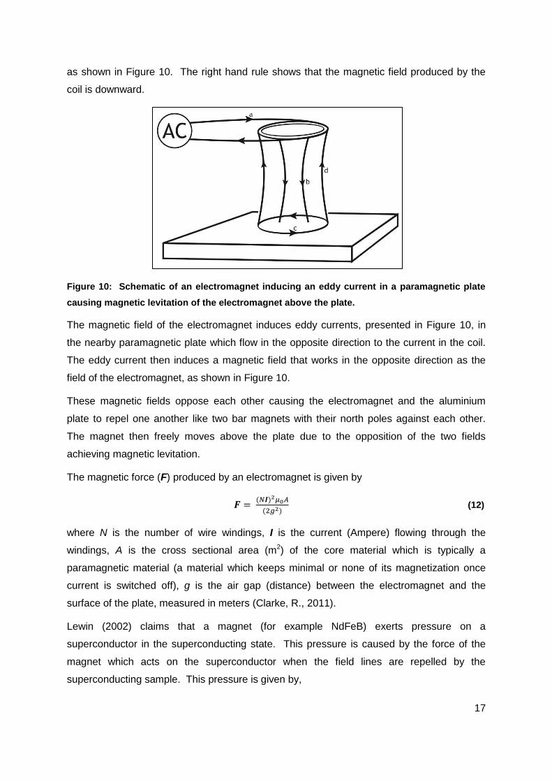
Lewin (2002) showed how magnetic levitation may be achieved using an electromagnet and
a paramagnetic metal plate. An alternating current flowing in a coil induces a magnetic field,
17
as shown in Figure 10. The right hand rule shows that the magnetic field produced by the
coil is downward.
Figure 10: Schematic of an electromagnet inducing an eddy current in a paramagnetic plate
causing magnetic levitation of the electromagnet above the plate.
The magnetic field of the electromagnet induces eddy currents, presented in Figure 10, in
the nearby paramagnetic plate which flow in the opposite direction to the current in the coil.
The eddy current then induces a magnetic field that works in the opposite direction as the
field of the electromagnet, as shown in Figure 10.
These magnetic fields oppose each other causing the electromagnet and the aluminium
plate to repel one another like two bar magnets with their north poles against each other.
The magnet then freely moves above the plate due to the opposition of the two fields
achieving magnetic levitation.
The magnetic force (F) produced by an electromagnet is given by
(12)
where N is the number of wire windings, I is the current (Ampere) flowing through the
windings, A is the cross sectional area (m2) of the core material which is typically a
paramagnetic material (a material which keeps minimal or none of its magnetization once
current is switched off), g is the air gap (distance) between the electromagnet and the
surface of the plate, measured in meters (Clarke, R., 2011).
Lewin (2002) claims that a magnet (for example NdFeB) exerts pressure on a
superconductor in the superconducting state. This pressure is caused by the force of the
magnet which acts on the superconductor when the field lines are repelled by the
superconducting sample. This pressure is given by,
18
(13)
where P is the pressure measured in Pascal (Lewin, 2002).
To determine the levitation force delivered by a permanent magnet on a superconductor in
the Meissner state, which causes the magnet to levitate above the superconductor, Equation
13 is multiplied by the cross sectional area of the magnet which gives
(14)
where F is the force (N), A is the area (m2) of the magnet. This levitation force between the
superconductor and the magnet is the result of the interaction between the magnetic field of
a ferromagnetic material and a diamagnetic material (Lewin, 2002).
Superconducting levitation by means of forces generated between magnets and subcritical
cooled superconductors in the Meissner state is also an example of magnetic suspension
which is used in passive magnetic bearings.
Magnetic bearings are categorised as active magnetic bearings or passive magnetic
bearings. Active magnetic bearings (AMBs) make use of electromagnets while passive
magnetic bearings (PMBs) make use of permanent magnets (which are made from
ferromagnetic materials) or superconductor- and-permanent magnet combinations (Bleuler,
et al., 2009).
AMBs can actively be controlled, whereas PMBs cannot. For this reason AMBs are
favoured above PMBs. AMBs are controlled using electromagnets, a feedback control loop,
sensors, power amplifiers and other hardware and software (Bleuler, et al., 2009).
In contrast to AMBs, PMBs make use of permanent magnets only. It is physically impossible
to have a purely passive suspension of a rigid body in all of its six degrees of freedom, using
only permanent magnets (µr >> 1) in a stationary configuration (Bleuler, et al., 2009). The
system will always have at least one unstable degree of freedom according to Earnshaw’s
theorem (Bleuler, et al., 2009; Chen, et al., 1998).
Suspensions of this sort require the addition of gyroscopic forces or a dynamic controlling
device or a force of different physical origin to stabilize the passive magnetic bearing
arrangement (Bleuler, et al., 2009; Chen, et al., 1998). Stabilization can be achieved by
using a mechanical bearing, an active electromagnet, and superconductor-to-magnet or
diamagnet-to-magnet interactions (Bleuler, et al., 2009).

19
AMBs have also been used in PMB setups to stabilize the system by adding an AMB or
AMBs to the PMB setup. Examples of such stabilization are found in turbo molecular pumps
(Bleuler, et al., 2009). A disadvantage of PMBs is that they have very low damping.
Mechanical or electromagnetic damping elements are necessary to provide suitable external
damping forces required in the system. Thus AMBs are used to provide damping in a PMB
setup (Bleuler, et al., 2009).
2.2 Research
The literature gathered in this study is covered under the following headings:
Superconducting levitation
Modelling
2.2.1 Superconducting levitation
The flux trapping effect of superconductors is temperature dependent as proven by Gruss et
al. (2001) who found that at liquid nitrogen temperature, (77 K or -196.15 °C) the trapped
field in pure YBCO was 0.8 T but at 57.9 K (-215.25 °C) the field was measured at 4.6 T
(Gruss, et al., 2001).
Fuchs et al. (2005) conducted an experiment using bulk YBCO (YBa2Cu3O7-x) disks of up to
50 mm in diameter to demonstrate the trapped field properties of the YBCO superconducting
sample. The YBCO disk was cooled with liquid nitrogen. An external field was applied in
the axial direction of the YBCO and then turned off. Pinned flux lines remained in the
sample (Fuchs, et al., 2005).
A Hall sensor was used to scan the distribution of the trapped field in the superconductor.
The maximum field Bo was found in the centre of the YBCO disks (Fuchs, et al., 2005). It
was also found that this field increases with the critical current density and size of the disk.
By chemical doping with Ag and Zn and neutron irradiation, improvements were made in flux
pinning properties resulting in stronger levitation forces (Fuchs, et al., 2005; Gruss, et al.,
2001; Fuchs, et al., 2003).
Fuchs et al. (2005) used an YBCO superconductor (34 mm diameter sample) and Sm-Co
permanent magnet (25 mm diameter) to measure the force between the magnet and the
superconductor. The YBCO was cooled at zero-field to 77K which for this case means that
the YBCO sample was cooled at a distance far from the magnet (Fuchs, et al., 2005).

20
Fuchs et al. (2005) then reduced the distance between the magnet and superconductor
which caused a repulsive force to develop because of the induced shielding current on the
superconductor. A maximum levitation force of 100 N was measured at a small distance
between the magnet and superconductor. The levitation pressure was 204 kPa over an area
of approximately 491 mm2 for this force at a distance of 2 mm between the magnet and
superconductor (Fuchs, et al., 2005).
Experimental research that was conducted proved that the magnetic force between a
magnet and a superconductor increases with a decrease in the distance between the
magnet and superconductor (Chen, et al., 1998; Fuchs, et al., 2005; Neves, et al., 2002;
Hauser, 1997; Fuchs, et al., 2003). A magnet levitating above a superconducting sample is
stabilized laterally as well as vertically because of the forces caused by flux pinning (Fuchs,
et al., 2005; Fedda, et al., 2007).
Levitation of a permanent magnet above YBCO thin films was successfully achieved by
Schönhuber et al. (1994). Forces produced between the YBCO thin film and the magnet,
were found to be lower than forces produced between bulk YBCO and the magnet.
However, the magnet and the thin film combination had stronger lateral and vertical stiffness’
compared to the bulk YBCO and magnet pair which were tested (Schönhuber, et al., 1994).
Chen et al. (1998) found that stronger levitation forces are obtained by using top seeded
melt textured YBCO samples instead of sintered YBCO samples. Levitation forces with
magnitudes of three orders higher were obtained by using top seeded melt textured YBCO
samples, compared to levitation forces using sintered YBCO samples. Single grain crystal,
melt textured grown YBCO samples also have superb magnetic shielding and field trapping
capabilities (Chen, et al., 1998).
In a study of the performance of NdFeB and ferrite magnets in superconducting linear
bearings with bulk YBCO samples, de Andrade Jr et al. (2003) found that NdFeB magnets
produced magnetic forces an order of magnitude larger than that of ferrite magnets. The
NdFeB magnets also produced greater magnetic stiffness compared to the ferrite magnets
while levitating above a bulk YBCO rail (de Andrade Jr., et al., 2003).
2.2.2 Modelling
To analyse forces obtained in superconducting levitation, modelling has been done by
means of numerical calculations and finite element methods, using code and programming
algorithms.

21
Neves et al. (2002) used the finite element method (FEM) and the Bean Critical State Model
(BCSM) to simulate the levitation force between a permanent magnet and a superconductor.
ANSYS MULTIPHYSICS 5.7 was used to calculate the levitation force in two dimensions.
The forces from the simulation were then compared to actual measured forces (Neves, et
al., 2002).
Neves et al. (2002) found that for small air gaps of 5 mm or less, the simulated force curves
and the experimental measured force curves were in agreement. However for air gaps
larger than 20 mm the simulated force curves deviated from the experimental measured
force curves (Neves, et al., 2002).
Figure 11 is a representation of the simulated magnetic flux density which was obtained by
Neves et al. (2002). The magnetic flux did not penetrate the superconductor as the
superconductor repelled the flux clearly demonstrating the Meissner effect.
Figure 11: Schematic of magnetic field and superconductor interaction. The magnetic field of
the magnet is repelled by the superconductor and does not penetrate the superconductor at
all (Modified after Neves, et al., 2002).
Hauser (1997) made use of the ANSYS-code to determine the forces generated between a
superconductor and a magnet. To consider partial flux penetration in FEM analyses, Hauser
(1997) suggested setting the relative permeability to a value between 0 and 1 for the
superconductor in the simulations.
Hauser (1997) also assumed a very high electrical conductivity for the superconductor in
finite element code to consider partial flux penetration. Partial flux penetration is referred to
as the non-perfect diamagnetic model. The perfect diamagnetic model is based on the
assumption of complete flux penetration. Hauser found that using the non-perfect model in

22
calculations gave partial good agreement of curves for force versus distance between
measured and calculated data (Hauser, 1997).
Hauser (1997) developed a user element for the ANSYS code which was used to solve for
the forces between a superconducting disk and a disk magnet which would obtain better
results than using the non-perfect diamagnetic model in calculations. The element named
SUPRA105 was written to include three models for the electromagnetic behaviour of an
HTSC and magnetic field dependencies for the critical current density Jc(B) (Hauser, 1997).
The three models that are included in the SUPRA105 element, according to Hauser (1997),
are:
Bean model, Jc(B) = C
Kim model, Jc(B).(B0 + B) = C
Matsushita model, Jc(B) = Jc0.B-1/2
The SUPRA105 element was then used with the critical state model and the frozen field
model respectively to calculate the forces between the superconductor and magnet. The
frozen field model and critical state model are existing superconductor models (Hauser,
1997).
According to Hauser (1997) the critical state model gives good results for the calculation of
levitation force. It is also stated that the critical state model is used to evaluate large
levitation forces between a bulk HTSC and a magnet (Tsuchimoto, 2001). Hauser (1997)
gives the critical state model as:
| |
| | | |
| |
According to Hauser (1997) the frozen field model is used to calculate the levitation forces
and can handle horizontal restoring forces as well. Tsuchimoto (2001) states that the frozen
field model is based on an assumption that fluxoid are fixed at pinning points on the surface
of the HTS. Tsuchimoto (2001) also used the frozen field model to evaluate the stiffness of
horizontal restoring force between a bulk superconductor and magnet. Hauser (1997) gives
the frozen field model as:
| |
| | | |

23
| |
where Fl (N) is the local force acting on the fluxoid, Jc is the superconducting critical current
density (A/m2) and Fp (N) is the pinning force.
Hauser (1997) stated that results obtained from simulations using the critical state model
and frozen field model with the SUPRA105 element clearly corresponded to measured
results that were obtained from experimental tests conducted by Hauser (1997).
According to Chen et al. (1998) the force between a zero-field cooled superconductor and a
magnet is given by
∫ (15)
where F is the force (N), B is the flux density (T) and V is the volume (m3). Chen et al.
(1998) proved that stronger levitation forces are obtained by increasing the external
magnetic flux density and increasing the volume of the superconductor.
Chen et al. (1998) stated that an analytical solution of Equation 15 for forces between a disc-
shaped permanent magnet and a superconductor is not readily available. This was ascribed
to the non-uniform magnetic field and the current density which is a function of the applied
field. However Chen et al. (1998) easily measured the forces between a magnet and a
superconductor by experimental studies.
Chen et al. (1998) found that the levitation force is increased by increasing the field cooling
gap for a superconductor and magnet while cooling the superconductor. However the
stability or lateral stiffness decreased as the field cooling gap was increased.
The field cooling gap is the air gap between the superconductor and magnet while the
superconductor is cooled and the distance at which the permanent magnet levitates after
being pinned. Masses between 2.5 kg and 4 kg could be levitated for different magnet and
superconductor configurations (Chen, et al., 1998).
Chen et al. (2001) presented an empirical method to calculate the magnitude of the forces
between a disc-shaped permanent magnet and a superconductor. Chen et al. (2001) states
that the current density Jc(r,z) of the current induced by the magnet’s applied field of the
superconductor can be divided into two parts. The first part is the current density on the
surface, Js,s and the second part is the volume current density Jv,s (Chen, et al., 2001).
Both these current densities are used to determine the surface, Bs,z and volume, Bv,z
magnetic flux densities of the superconductor in the z-axis. A third current density exists on
the surface of the permanent magnet Js,m. This is because the magnetic flux density of the

24
permanent magnet can be treated as a ring of surface current which has a surface current
density Br,m (Chen, et al., 2001).
According to Chen et al. (2001) the magnetic levitation force is calculated as the interaction
force between the currents on the superconductor and the currents on the magnet. Thus the
force is given by the summation of the forces caused by the interaction of the flux density of
the magnet and the Js,s (surface current density) and Jv,s (volume current density) terms of
the superconductor which are given as Fz,s and Fz,v respectively:
∫ ∫
∫ ∫ ∫
where r, ϕ and z represent the coordinates in a cylindrical coordinate system, h and t
represent the thickness of the superconductor and magnet, αz is a directional vector and b1
to b2 is the region along the r axis on the superconductor (Chen, et al., 2001).
Perini et al. (2009) used the E-J power law to develop a numerical model for the
superconductor material. The equation is given by
(‖ ‖
)
‖ ‖
where E is the electric field, E0 is the electric field at the time t = 0, J the current density, Jc
the critical current density, B the magnetic field and T the temperature (Perini, et al., 2009).
Perini et al. (2009) successfully validated the data obtained from the numerical model with
the experimental data for the levitation of a magnet above an MgB2 disk superconductor.
Fedda et al. (2007) derived three mathematical equations to calculate the levitation force
between a small magnet and a superconducting ring using a dipole-dipole interaction model.
Fedda et al. (2007) found that the levitation force on the magnet increased to a maximum
when the distance between the magnet and centre of the ring was decreased. The force
then decreased to zero when the magnet was moved to the centre of the ring (Fedda, et al.,
2007).
The magnet was defined as a single magnetic dipole that levitates at a distance h from the
centre of the superconducting ring. Fedda et al. (2007) also assumed that the magnetic
moment of the dipole was 0.001 Am2. Field cooling and zero field cooling were not
considered in the model. Figure 12 is a schematic representation of the magnetic dipole

25
and superconducting ring model, for which the equations presented below were derived for
(Fedda, et al., 2007).
Figure 12: Schematic of the superconductor ring and the magnetic dipole (μ) at angle θ for
which Fedda et al., (2007) derived the equations listed (Modified after Fedda et al. 2007).
The three equations were derived for three special cases. Each case is given with its
corresponding equation below (Fedda, et al., 2007):
1. A superconducting ring has an infinite outer radius (b = ∞). The force is calculated
in the limit, which gives the equation:
( )
(16)
2. A superconducting ring for which the inner radius approaches zero. The force is
calculated in the limit, , as:
(17)
3. A superconductor that is very thin. The superconductor is much thinner than what
the distance is from which the dipole levitates from the superconductor’s centre (t <<
h) and gives:
(18)
with , and .
According to Fedda at al. (2007) calculated results were in good qualitative agreement with
experimental results. Fedda et al. (2007) also found calculated results to be in agreement
with the experimental results for the forces between a small magnet and superconducting

26
ring obtained by Ma et al. (2001). In these experiments the superconductor was field cooled
and zero-field cooled and the forces were measured between the magnet and
superconductor (Ma, et al., 2001).
2.3 Summary
A background on superconductivity and superconducting levitation fundamentals has been
given in the preceding chapters, however much literature has been gathered on levitation
capabilities of superconductors and the improvement thereof. Investigation has also been
conducted on levitation force determination between magnets and superconductors.
However, during the course of the literature study no literature could be found on
superconducting levitation as suspension mechanism in cryogenic storage containers.
After considering the research in the literature study it was only logical to investigate the
technology and the phenomenon of superconducting levitation in concepts of cryogenic
containers for the stable suspension of a liquid hydrogen container within another, to reduce
thermal conductivity in a non-filling or delivery state of the stored H2.
2.4 Purpose of study
The purpose of this study now is to suggest a concept for the storage of liquid hydrogen,
typically for vehicular transport applications, in which an inner vessel is magnetically
suspended in a vacuum drawn outer vessel. It is also the purpose of this study to validate
the concept, by determining the magnitude of forces obtainable between magnets and
superconductors in the superconducting state. In this study no attempt will be made to
evaluate the influence of the above mentioned on filling and delivery to the container.
27
Chapter 3: Conceptual design
In Chapter 1 arguments were presented that liquid hydrogen can be stored in a container of
lesser volume than the storage volume required for storage of compressed gaseous
hydrogen of equal amount. It was also argued that if liquid hydrogen storage is pursued,
heat transfer from the environment to the hydrogen should be reduced to a minimum.
As discussed in Chapter 1, there are different container patents that exist for hydrogen
storage which limit heat transfer to the hydrogen. However unacceptable heat transfer from
the environment to the hydrogen still occurs through physical supports, which leads to
hydrogen boil-off. These losses can be reduced by possibly magnetically suspending an
inner container within another container and thereby eliminating the use of physical
supports.
In an attempt to reduce hydrogen boil-off, a conceptual design for storage of liquid hydrogen
is presented and discussed for which superconducting levitation is suggested as magnetic
suspension mechanism between an inner- and outer container. The focus of the conceptual
design is a first approximation of the feasibility of magnetic suspension of said container
concept and not of the container itself. It should also be noted that for this study the effects
of the inlet/outlet pipe are ignored.
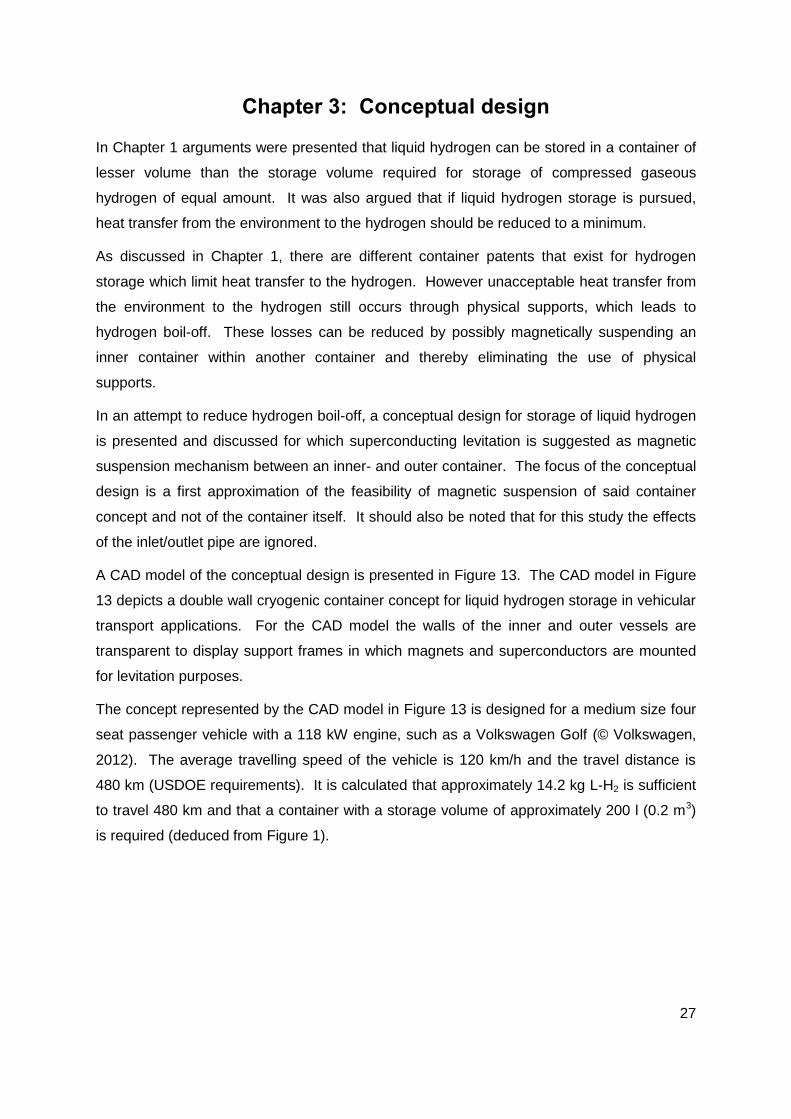
A CAD model of the conceptual design is presented in Figure 13. The CAD model in Figure
13 depicts a double wall cryogenic container concept for liquid hydrogen storage in vehicular
transport applications. For the CAD model the walls of the inner and outer vessels are
transparent to display support frames in which magnets and superconductors are mounted
for levitation purposes.
The concept represented by the CAD model in Figure 13 is designed for a medium size four
seat passenger vehicle with a 118 kW engine, such as a Volkswagen Golf (© Volkswagen,
2012). The average travelling speed of the vehicle is 120 km/h and the travel distance is
480 km (USDOE requirements). It is calculated that approximately 14.2 kg L-H2 is sufficient
to travel 480 km and that a container with a storage volume of approximately 200 l (0.2 m3)
is required (deduced from Figure 1).

28
Figure 13: Isometric view of a CAD model of the double wall cryogenic container concept for
liquid hydrogen storage in vehicular transport in which suspension of the inner vessel is
achieved by electromagnetic- and superconducting levitation.
For calculations concerning the design of the container presented in Figure 13, refer to the
EES Code in Appendix B. The hydrogen container concept presented in Figure 13 is
covered under the following headings:
Outer vessel and connected parts
Inner vessel and internals
Magnetic suspension
3.1 Outer vessel and connected parts
The outer vessel and connected parts consist of:
Electromagnet
Outer vessel
Outer vessel support frame
Permanent magnets
Magnet caps
Outer vessel
Inner vessel
Inner vessel support frame Outer vessel support frame Superconductor

29
3.1.1 Electromagnet
An electromagnet is used to levitate the inner container within the outer container. The
electromagnet which is an air coil (magnet has no metal core) is positioned below the outer
vessel centre as presented in the section view of the CAD models in Figure 14. The
electromagnet has 500 turns of copper wire of 0.0007 mm thickness and has a core cross
sectional diameter of 0.1 m.
The electromagnet is designed to run at 220 V with a 14 A alternating current which induces
a magnetic field with strength of 362.5 kA/m. It is designed to provide a lift force of
approximately 660 N, which is to lift approximately 66 kg. The force deliverable by the
electromagnet is above the required force of 610 N, as the filled inner vessel with internals
weighs approximately 62.2 kg. For simplicity reasons the electromagnet is presented as a
round solid disk in Figure 14.
Figure 14: CAD models of a section view and an isometric view of the electromagnet mounted
in its rack below the outer vessel centre.
The electromagnet is secured in a rack which holds it in place beneath the centre of the
outer vessel. The design of the rack is not of interest for this study as the focus is on the
magnetic suspension mechanism. For this reason it is not further discussed.
3.1.2 Outer vessel
A CAD model of the outer vessel is presented in Figure 15. The outer vessel is a cylindrical
storage vessel with hemispherical end caps. It is designed to be positioned horizontally in a
vehicle and to encapsulate the inner vessel as well as a support frame. Permanent magnets
are mounted in the support frame for levitation purposes. A medium vacuum of 1 kPa is
Electromagnet
Isometric view Section view
Outer vessel
Electromagnet rack
Inner vessel

30
drawn in the outer vessel to reduce convection between the two vessels and ultimately to
reduce hydrogen boil-off (NPL Management Limited, 2012).
Figure 15: Isometric view of a CAD model of the outer vessel and connected parts.
The inner diameter of the outer vessel is approximately 0.606 m and the length of the vessel
is approximately 1.16 m. The wall thickness of the outer vessel is 4 mm. 304L stainless
steel is the selected material for the outer vessel wall as it is used for cryogenic storage
applications (MatWeb, LLC, 2012). 304L stainless steel also has a high weldability which
ensures ease of joining the vessel and support frame parts.
304L stainless steel is ferromagnetic and due to its magnetic permeability (µ = 1.008) it
increases the magnetic flux density (B) produced by the electromagnet as discussed in
Chapter 2.1.1, derived from Equation 3. The stronger magnetic field in turn produces a
stronger magnetic force when the inner vessel is levitated by the electromagnet at the initial
filling of the container. The levitation of the inner container is discussed in Chapter 3.3.1.
3.1.3 Outer vessel support frame
In Figure 15 the vessel wall of the CAD model is transparent to show the outer vessel
support frame which is encapsulated in, and welded to the vessel. A CAD model of a
section view of the support frame is presented in Figure 16.
Outer vessel wall
Permanent magnet Support frame

31
Figure 16: Right sectioned view of the CAD model of the outer vessel support frame which
holds permanent magnets.
The frame consists of three parallel rings that are adjoined by beams with half rings that in
turn are joined to each of the outer rings. Permanent magnets are mounted in the rings and
half rings of the support frame for levitation purposes as discussed in Chapter 3.3.1. The
support frame is also made from 304L stainless steel for the same reasons stated as for the
use of 304L stainless steel for the outer vessel wall.
3.1.4 Permanent magnets
The permanent magnets provide magnetic flux which is trapped in the superconductors
(situated in the inner container support frame) to achieve levitation and ultimately
suspension of the inner container within the outer container. The permanent magnets are
secured in holes in the rings (Figure 17: Isometric view) with magnet caps which are welded
to the ring. Figure 17 also presents a close up view of a magnet cap securing a permanent
magnet in a hole.
In the section view of the CAD model presented in Figure 16, the magnets on the bottom of
the rings (those numbered 1) are the magnets that produce the levitation force that levitates
the inner vessel once the magnetic fields are pinned in the corresponding superconductors,
ultimately providing magnetic suspension. There are three such magnets.
The magnets on the top, left and right parts of the rings (numbered 2 through 5) provide a
constraint on the inner vessel prohibiting it from moving around in the outer vessel once the
magnetic fields are pinned in corresponding superconductors. The magnets are 22 mm in
diameter and 25 mm long.
Half ring
Full ring Beam
Inlet
Permanent magnet
1
2
3
4 5

32
Figure 17: CAD models of an isometric view and a close up section view of a permanent
magnet mounted in a ring.
The strongest magnetic forces possible are required for the levitation of the inner vessel.
High magnetic stiffness is also required for the suspension system as this determines the
movement of the inner vessel in the outer vessel if there is any disturbance force that acts
on the container setup. An example of a disturbance force is when the vehicle drives over a
bump in the road, which causes the inner vessel to move within the outer vessel.
Due to the findings of De Andrade Jr et al. (2003) mentioned in the literature survey that
NdFeB magnets produce magnetic forces of an order larger than that of ferrite magnets and
that NdFeB magnets have greater magnetic stiffness’ than ferrite magnets while levitating
above a bulk YBCO rail, NdFeB magnets were selected above sintered magnets for this
concept.
These magnets are N37 neodymium magnets. The N in the name shows that the magnet is
made from neodymium (NdFeB Specialists E-Magnets UK Limited, 2011). The number
following the N is the (BH)max (maximum energy product) given in MGOe (Mega Gauss-
Oersted). The corresponding residual induction (Br) of a N37 magnet is 1.24 T (Sable
Magnetics, 2011).
3.1.5 Magnet caps
The magnet caps are small hollow cylindrical shells that fit over the magnets and are welded
to the rings to secure the magnets in position. The caps also protect the magnets from
being damaged by the container when it rests on the caps before it is levitated and filled.
Close-up section view of permanent
magnet secured with cap in ring
Magnet cap
Permanent magnet
Permanent
magnet hole
Magnet secured
with cap in ring
Support ring
Isometric View

33
The magnet caps are made from 304L stainless steel and due to the fact that it is a
ferromagnetic material the caps align the magnetic field of the magnet directing it at the
superconductor. Figure 18 is a CAD model of an isometric sectioned view of the magnet
cap.
Figure 18: Sectioned isometric view of a CAD model of the permanent magnet cap.
Should the suspension fail, that is if the hydrogen is depleted and the superconductors’
temperature rise above Tc causing breakdown of the pinning effect, the caps would also
protect the magnets from impact by the inner vessel.
3.2 Inner vessel and internals
The inner vessel and internals consist of:
Inner vessel
Inner vessel support frame
Superconductors
Support cap
3.2.1 Inner Vessel
Figure 19 presents a CAD model of the inner vessel in isometric view. The inner vessel is a
cryogenic capable cylindrical storage vessel with hemispherical end caps designed to store
the required 14.2 kg liquid hydrogen at sub-cooled temperature (20 K) and high pressure (10
MPa).
To satisfy the 200 l (0.2 m3) volume requirement the inner vessel is designed with a total
length, inner diameter and wall thickness of approximately 1.1 m, 0.53 m and 4 mm
respectively. Due to the 4 mm wall thickness the vessel occupies a space of approximately
210 l (0.21 m3) and weighs approximately 33 kg because of the density of Ti-5Al-2.5Sn ELI
(4480 kg/m3) (Collings, 1994).

34
Figure 19: Isometric view of a CAD model of the inner vessel and internals.
To safely store liquid hydrogen the vessel wall is made of Ti-5Al-2.5Sn ELI, a material which
is used in cryogenic pressure vessels. Ti-5Al-2.5Sn ELI is a paramagnetic material and due
to the alternating current in the electromagnet it will levitate above the electromagnet within
the outer vessel. This is based on the magnetic levitation principal discussed in Chapter
2.1.4, in which an electromagnet levitates above a paramagnetic plate.
Due to the paramagnetic behaviour, the material has no effect on the permanent magnets’
magnetic fields and will not disrupt the levitation forces or affect the suspension of the inner
vessel. Due to good weldability of the material, the vessel and internal parts are easy to join.
3.2.2 Inner vessel support frame
For the inner vessel concept presented in Figure 19 the vessel wall is transparent to show
the inner vessel support frame which is encapsulated in the vessel. A CAD model of a
section view of the support frame is presented in Figure 20.
Figure 20: Right sectioned view of the CAD model of the inner vessel support frame which
holds superconductors.
Superconductor
Support frame
Inner vessel wall
Half ring Full ring
Beam
Inlet
Superconductor
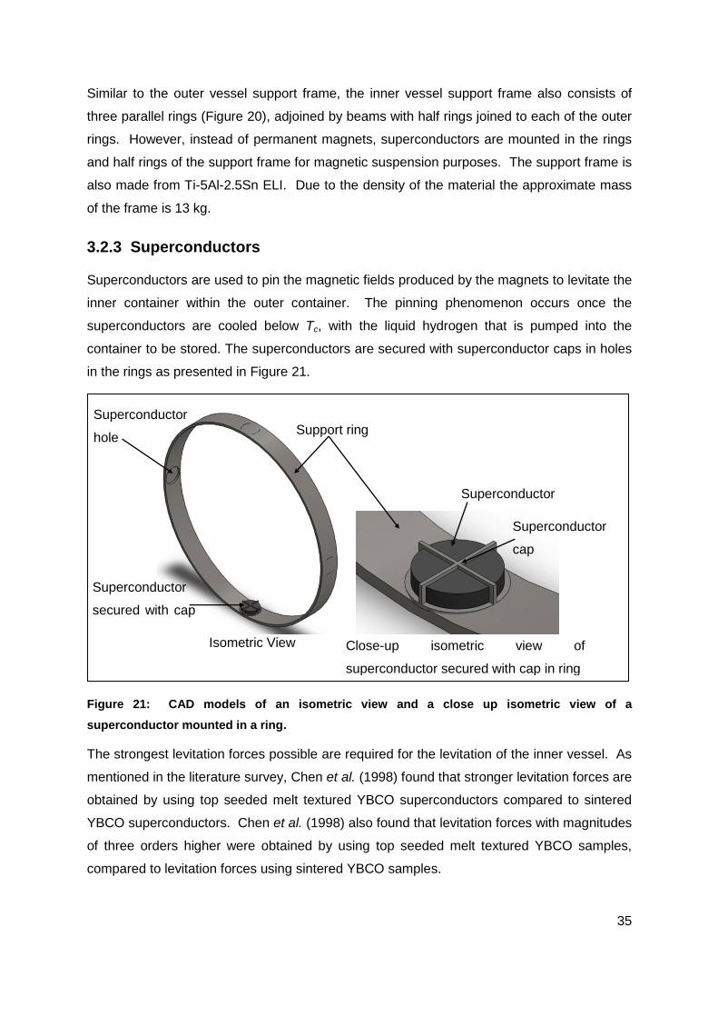
35
Similar to the outer vessel support frame, the inner vessel support frame also consists of
three parallel rings (Figure 20), adjoined by beams with half rings joined to each of the outer
rings. However, instead of permanent magnets, superconductors are mounted in the rings
and half rings of the support frame for magnetic suspension purposes. The support frame is
also made from Ti-5Al-2.5Sn ELI. Due to the density of the material the approximate mass
of the frame is 13 kg.
3.2.3 Superconductors
Superconductors are used to pin the magnetic fields produced by the magnets to levitate the
inner container within the outer container. The pinning phenomenon occurs once the
superconductors are cooled below Tc, with the liquid hydrogen that is pumped into the
container to be stored. The superconductors are secured with superconductor caps in holes
in the rings as presented in Figure 21.
Figure 21: CAD models of an isometric view and a close up isometric view of a
superconductor mounted in a ring.
The strongest levitation forces possible are required for the levitation of the inner vessel. As
mentioned in the literature survey, Chen et al. (1998) found that stronger levitation forces are
obtained by using top seeded melt textured YBCO superconductors compared to sintered
YBCO superconductors. Chen et al. (1998) also found that levitation forces with magnitudes
of three orders higher were obtained by using top seeded melt textured YBCO samples,
compared to levitation forces using sintered YBCO samples.
Close-up isometric view of
superconductor secured with cap in ring
Superconductor
cap
Superconductor
Superconductor
hole
Superconductor
secured with cap
Support ring
Isometric View
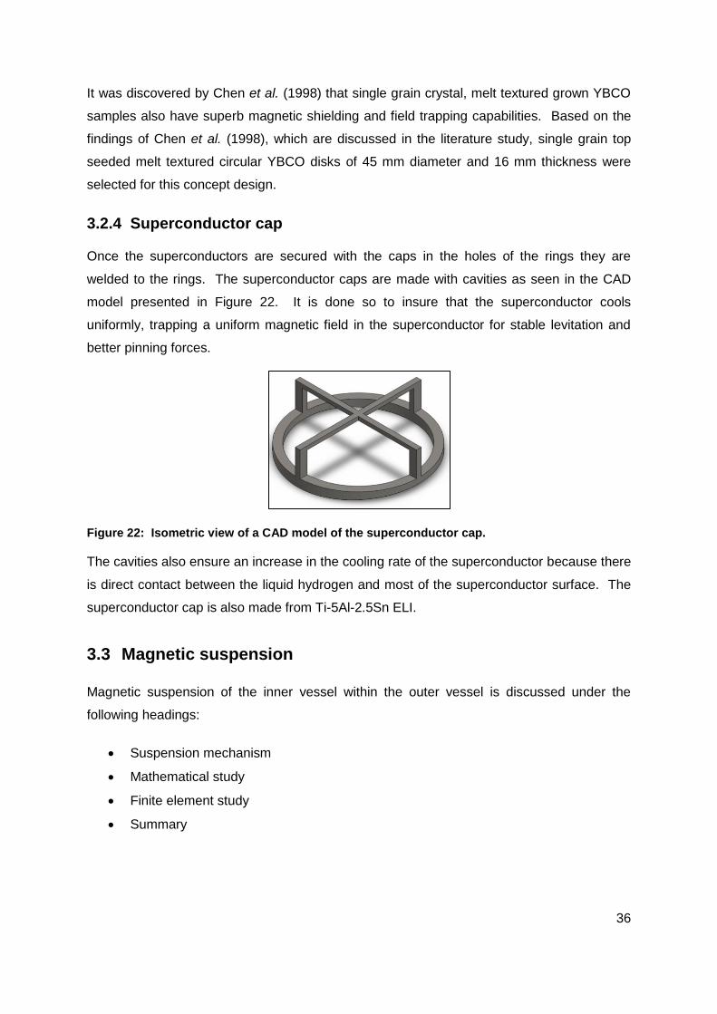
36
It was discovered by Chen et al. (1998) that single grain crystal, melt textured grown YBCO
samples also have superb magnetic shielding and field trapping capabilities. Based on the
findings of Chen et al. (1998), which are discussed in the literature study, single grain top
seeded melt textured circular YBCO disks of 45 mm diameter and 16 mm thickness were
selected for this concept design.
3.2.4 Superconductor cap
Once the superconductors are secured with the caps in the holes of the rings they are
welded to the rings. The superconductor caps are made with cavities as seen in the CAD
model presented in Figure 22. It is done so to insure that the superconductor cools
uniformly, trapping a uniform magnetic field in the superconductor for stable levitation and
better pinning forces.
Figure 22: Isometric view of a CAD model of the superconductor cap.
The cavities also ensure an increase in the cooling rate of the superconductor because there
is direct contact between the liquid hydrogen and most of the superconductor surface. The
superconductor cap is also made from Ti-5Al-2.5Sn ELI.
3.3 Magnetic suspension
Magnetic suspension of the inner vessel within the outer vessel is discussed under the
following headings:
Suspension mechanism
Mathematical study
Finite element study
Summary

37
3.3.1 Suspension mechanism
Magnetic suspension of the inner vessel is achieved by two forms of magnetic levitation.
The first is electromagnetic levitation for which an electromagnet provides the required force
to levitate the inner vessel whilst liquid hydrogen is being pumped into the vessel. The
second is by means of forces generated by the interaction between superconductors in the
superconducting state and the magnetic fields of permanent magnets, for which the
magnetic fields are pinned in the superconductors.
To magnetically suspend the inner vessel, an electromagnet (discussed in Chapter 3.1.1)
driven by an alternating current is used to supply a magnetic field which induces eddy
currents in the vessel wall and in turn induces an opposing magnetic field in the
paramagnetic inner vessel wall. This is done to position the inner vessel and outer vessel so
that the superconductors and permanent magnets, in their respective support frames, are
positioned with a 10 mm levitation gap (air gap) in a concentric position.
As electromagnetic suspension takes place the inner vessel is filled with liquid hydrogen,
which in turn cools the superconductors below their Tc and induces the superconducting
state. The superconductors then pin the magnetic fields of the permanent magnets. The
field of the electromagnet is also pinned in the superconductor, but does not affect
superconducting levitation as the electromagnet is switched off once the magnetic fields of
the permanent magnets are pinned.
Figure 23 is a close up sectioned view of a CAD model of a superconductor and a
permanent magnet secured in a concentric position 10 mm apart. Both magnet and
superconductor are secured in their respective support frames within their vessels by use of
magnet- and superconductor caps. There is a 3 mm gap between the inner vessel wall and
the magnet caps if the inner vessel moves as the vehicle drives over a bump.
The levitation force that works on the superconductors causes the superconductors to
levitate which in turn causes the support frame within the inner vessel to levitate resulting in
the levitation of the inner vessel because the superconductors are secured to the frame with
superconductor caps.

38
Figure 23: Close up frontal sectioned view of a CAD model of a superconductor and magnet
mounted their specific support frames within their specific containers with an air gap of 10 mm
between the magnet and superconductor.
To levitate the filled inner container by means of superconducting levitation, a permanent
magnet is required which delivers a magnetic force of 610 N. Equation 14 was used to
calculate the appropriate size of a magnet required in combination with a superconductor in
the superconducting state to levitate the inner vessel.
It was calculated that a magnet of approximately 36 mm in diameter is required to levitate
the total mass of the filled container. The possible instability of the container levitated by
only one magnet is countered by the addition of more magnets to produce the levitation
force required to levitate the inner vessel.
It was therefore decided that three smaller magnets would suffice to provide the required
levitation force, by adding the forces delivered by the magnets. To determine the size of the
smaller magnets the total force required to lift the inner container was divided by three. With
the use of Equation 14, the required size of the smaller magnets was calculated at
approximately 22 mm diameter. According to calculations these smaller magnets each
produce a force of approximately 203 N.
However Equation 14 cannot be used to calculate the forces between a magnet and
superconductor as a function of the air gap because it is derived for the maximum force a
magnet can deliver and does not consider the distance between the superconductor and
magnet.
Inner vessel wall
Inner vessel
support frame
Superconductor cap
Superconductor
Permanent magnet cap
Permanent magnet
Outer vessel wall
Outer vessel
support frame
10 mm 4 mm 3 mm
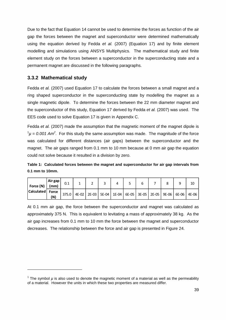
39
Due to the fact that Equation 14 cannot be used to determine the forces as function of the air
gap the forces between the magnet and superconductor were determined mathematically
using the equation derived by Fedda et al. (2007) (Equation 17) and by finite element
modelling and simulations using ANSYS Multiphysics. The mathematical study and finite
element study on the forces between a superconductor in the superconducting state and a
permanent magnet are discussed in the following paragraphs.
3.3.2 Mathematical study
Fedda et al. (2007) used Equation 17 to calculate the forces between a small magnet and a
ring shaped superconductor in the superconducting state by modelling the magnet as a
single magnetic dipole. To determine the forces between the 22 mm diameter magnet and
the superconductor of this study, Equation 17 derived by Fedda et al. (2007) was used. The
EES code used to solve Equation 17 is given in Appendix C.
Fedda et al. (2007) made the assumption that the magnetic moment of the magnet dipole is
1µ = 0.001 Am2. For this study the same assumption was made. The magnitude of the force
was calculated for different distances (air gaps) between the superconductor and the
magnet. The air gaps ranged from 0.1 mm to 10 mm because at 0 mm air gap the equation
could not solve because it resulted in a division by zero.
Table 1: Calculated forces between the magnet and superconductor for air gap intervals from
0.1 mm to 10mm.
At 0.1 mm air gap, the force between the superconductor and magnet was calculated as
approximately 375 N. This is equivalent to levitating a mass of approximately 38 kg. As the
air gap increases from 0.1 mm to 10 mm the force between the magnet and superconductor
decreases. The relationship between the force and air gap is presented in Figure 24.
1 The symbol µ is also used to denote the magnetic moment of a material as well as the permeability
of a material. However the units in which these two properties are measured differ.
Air gap
(mm)0.1 1 2 3 4 5 6 7 8 9 10
Force
(N)375.0 4E-02 2E-03 5E-04 1E-04 6E-05 3E-05 2E-05 9E-06 6E-06 4E-06
Force (N)
Calculated

40
Figure 24: Graph of the relationship between levitation force and air gap obtained by
calculations.
3.3.3 Finite element study
A finite element (FE) study was conducted to determine the magnitudes of force between a
superconductor and a 22 mm diameter magnet. SolidWorks was used to draw geometry for
the FE model. ANSYS Multiphysics is the finite element software that was used in the FE
study. The geometry that was drawn in SolidWorks was imported into the geometry
component in ANSYS Multiphysics’ Workbench interface.
The magnet and superconductor geometry have fixed positions in the geometry component.
There is a separation in distance between the magnet and the superconductor. This
separation is referred to as the air gap which initially was set at 10 mm.
The model was imported on the XY plane to ensure that the axial direction of the magnet
and superconductor are on the z-axis with the superconductor below the magnet. Figure 25
displays the coordinate system in the right bottom corner of the figure. The geometry was
then added to a magnetostatic analysis system in ANSYS Multiphysics.
An additional plane was added to the bottom base of the magnet. It was defined as the
polarisation plane and used to allocate direction to the magnetic field flowing from the
magnet. Thus the direction of the magnetic field was set to be in the direction of negative z-
axis with respect to the global coordinate system. Figure 25 shows the polarization plane on
0.0
50.0
100.0
150.0
200.0
250.0
300.0
350.0
400.0
0.02.04.06.08.010.0
F (N
)
Air gap (mm)
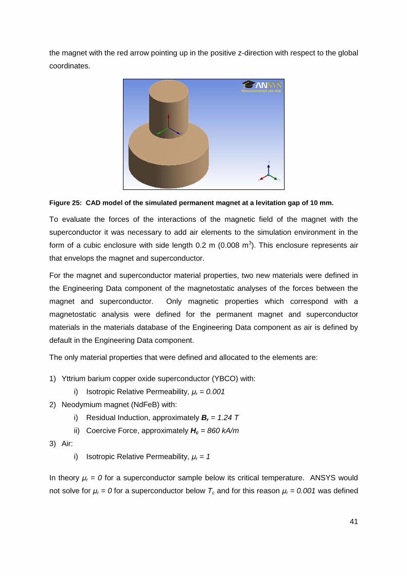
41
the magnet with the red arrow pointing up in the positive z-direction with respect to the global
coordinates.
Figure 25: CAD model of the simulated permanent magnet at a levitation gap of 10 mm.
To evaluate the forces of the interactions of the magnetic field of the magnet with the
superconductor it was necessary to add air elements to the simulation environment in the
form of a cubic enclosure with side length 0.2 m (0.008 m3). This enclosure represents air
that envelops the magnet and superconductor.
For the magnet and superconductor material properties, two new materials were defined in
the Engineering Data component of the magnetostatic analyses of the forces between the
magnet and superconductor. Only magnetic properties which correspond with a
magnetostatic analysis were defined for the permanent magnet and superconductor
materials in the materials database of the Engineering Data component as air is defined by
default in the Engineering Data component.
The only material properties that were defined and allocated to the elements are:
1) Yttrium barium copper oxide superconductor (YBCO) with:
i) Isotropic Relative Permeability, μr = 0.001
2) Neodymium magnet (NdFeB) with:
i) Residual Induction, approximately Br = 1.24 T
ii) Coercive Force, approximately Hc = 860 kA/m
3) Air:
i) Isotropic Relative Permeability, μr = 1
In theory μr = 0 for a superconductor sample below its critical temperature. ANSYS would
not solve for μr = 0 for a superconductor below Tc and for this reason μr = 0.001 was defined

42
in the YBCO material database, for the simulation to have a relative permeability of nearly
zero.
Although μr = 0.001 was defined for the YBCO material, other magnetic properties were not
defined for YBCO, because they are incompatible with the addition of relative permeability.
In the ANSYS Mechanical platform the materials were allocated to the different geometries.
An environment was defined in which the magnetic flux generated by the magnet was
measured. This was done by selecting the faces of the air enclosure and defining the six
faces as the “magnetic flux parallel” region boundaries.
A mesh that was automatically generated by the ANSYS Mechanical code was used to solve
the model. Use of the automatically generated default mesh was recommended by an
expert on ANSYS solutions in personal communication (Mr Francis van Ravenswaay). The
simulation was set to solve for one step of one second which was sufficient to gain a
solution.
Solution information was gathered by adding “Directional force” plots which displayed the
force summation over the magnet, superconductor and combination of the two. The latter
summation was done to see whether the forces balanced out over the permanent magnet
and YBCO superconductor.
Once the forces were determined at 10 mm the air gap was reduced by 1 mm, by manually
editing the geometry. The simulation was then re-run and solved and the resulting forces
were determined for the geometry with the updated air gap. These steps were repeated until
the resulting force was determined between the magnet and superconductor at an air gap of
0 mm.
Figure 26 is a graph of the magnitude of the forces at given air gaps, which were determined
in the simulation study, between a magnet and a superconductor below its Tc. The force on
the magnet (line labelled “PM”) increases as the air gap decreases from 10 mm to 1 mm. It
is also true for the reaction force on the superconductor (line labelled “YBCO”). The line
labelled “SUM” is the sum of these forces at each air gap interval.

43
Figure 26: Graph for levitation forces acting on the superconductor, magnet and the sums of
forces at each air gap interval obtained from simulations.
From Figure 26, at 10 mm the force on the superconductor should theoretically be 0 N,
because for a pinned field (µr = 0) the superconductor and magnet would be in equilibrium
with the magnet levitating above the superconductor. However the superconductor, µr =
0.001 was set in the simulation which is an approximated case of levitation and pinning.
Thus the action and reaction forces were not equal hence the sum of forces is not zero at
each interval. For µr = 0 (ideal case of levitation and pinning) the sum of forces is
theoretically zero at each interval, which indicates stable levitation of the magnet above the
superconductor.
The sum of forces was used as a measure of accuracy of the model, in which µr = 0.001 was
set, by comparing the sums of forces of the model with those of the ideal case of pinning (µr
= 0). It was found that the larger the difference between the sums of forces of the ideal case
(µr = 0) and approximated case (µr = 0.001), the less accurate the model is. The resulting
forces obtained for the approximated case are presented in Table 2 for the forces working on
the permanent magnet and superconductor.
-150.00
-100.00
-50.00
0.00
50.00
100.00
150.00
024681012 Forc
e (
N)
Air gap (mm)
Force (N)PM
Force (N)YBCO
Force (N)SUM

44
Table 2: Table for the forces determined in the simulation acting on the magnet and
superconductor and the sums of forces at each air gap interval.
As presented in Table 2, the sums of the forces at their specific air gaps do not deviate much
from the ideal case (µr = 0) where the sum of forces over each interval is zero. The largest
deviance is 1.16 N at air gap 10 mm. The deviance in the sums of force are plotted in Figure
26 and labelled “Force Sum”.
Note that the forces at 0 mm are not plotted on the graph. The reason for this is that once
the air gap is 0 mm the magnet and superconductor make contact creating conduction paths
which defeats the purpose of levitation as suspension mechanism.
ANSYS also calculated action and reaction forces at 0 mm, which were smaller than the
forces at 1 mm. This result is not accurate according to what was gathered in the literature
survey because the forces are to increase as the air gap nears 0 as Chen et al. (1998) found
during experimental tests.
3.3.4 Summary
The results obtained in the mathematical- and finite element studies for the forces acting
between a superconductor and a permanent magnet differ in magnitude as presented in
Figure 27. The forces obtained in the mathematical study (line labelled “Calculation”) have a
maximum force of approximately 0 N compared to the approximate 110 N obtained in the
finite element study (line labelled “Simulation”) at 1 mm air gap.
Position
(mm)10 9 8 7 6 5 4 3 2 1 0
Force (N)
PM5.30 10.25 11.75 15.04 20.10 28.46 35.49 53.84 74.04 110.81 4.19
Force (N)
YBCO-9.68 -10.71 -13.27 -17.15 -21.84 -29.46 -39.66 -55.08 -75.85 -109.91 -71.19
Force (N)
SUM-4.38 -0.46 -1.52 -2.11 -1.74 -1.00 -4.17 -1.24 -1.81 0.90 -67.00

45
Figure 27: Graph for levitation forces measured in the mathematical- and finite element study.
The force magnitude of the finite element study decreases with an increase in air gap,
whereas for the mathematical study it is constant 0 N. The discrepancies in magnitudes of
the forces between a magnet and superconductor obtained in the mathematical- and finite
element study is investigated in Chapter 4.2.
0.00
50.00
100.00
150.00
200.00
250.00
300.00
350.00
400.00
0246810
Forc
e (
N)
Air gap (mm)
Simulation
Calculation

46
Chapter 4: Concept validation
To assess the calculated levitation force magnitudes for the electromagnetic- and
superconducting suspension mechanism, experimental tests were carried out to measure
said levitation forces and ultimately validate the magnetic suspension concept. The
experimental procedures as well as the results obtained for the levitation force magnitudes,
during these tests are covered under the following headings:
Electromagnetic suspension
Superconducting suspension
4.1 Electromagnetic suspension
4.1.1 Experimental study
To validate the use of an electromagnet for magnetic suspension of the inner vessel an
electromagnet was built according to the specifications given in Chapter 3.1.1. It was
connected to a power source of 220 V and 14.5 A (alternating current). An aluminium plate
was then levitated above the electromagnet.
The magnetic levitation force between the plate and electromagnet was measured by
placing weights on the aluminium plate until the weight of the weights overcame the
levitation force. The electromagnet produced a levitation force that lifted approximately 2.24
kg. The corresponding levitation force is calculated at approximately 22 N which is far below
the required 610 N to suspend the inner vessel. The force produced by the magnet is also
far below the calculated force of 660 N, which the magnet was expected to produce.
4.1.2 Discussion
The weak force produced, is ascribed to the heat dissipation in the electromagnet as well as
impurities in the aluminium plate. It is also believed that due to the coil having many air gaps
between windings a uniform field could not be created inducing weaker eddy currents in the
aluminium plate.
A power consumption of 3.19 kW was calculated for the electromagnet which produced a 22
N levitation force. To produce a lift force of 610 N approximately 28 electromagnets that
produce a force of 22 N each, are required. This results in a power loss of approximately 90
kW for the sum total of electromagnets.

47
In the case of electromagnetic suspension as discussed in Chapter 3.3.1, 28 electromagnets
require approximately 0.75 g/s to drive the electromagnets, while filling of the container takes
place. If filling takes place for 2 minutes the required mass of hydrogen is approximately
0.09 kg L-H2 to drive the electromagnets while the superconductors make the transition from
the normal state to the superconducting state.
4.1.3 Conclusion and recommendations
It is the conclusion of this study that electromagnetic levitation must not be made use of as
suspension mechanism for the inner vessel. This conclusion is based on the loss of
hydrogen which is incurred to drive the electromagnet, while it is being used to levitate the
inner vessel during L-H2 filling.
It is recommended that another method is investigated to suspend the inner vessel within the
outer vessel as superconducting levitation is initialized. A possible method is the use of an
air bag which is positioned between the inner and outer vessel and attached to the outer
vessel inner wall. While superconducting levitation is induced the air bag is inflated to
position the inner vessel within the outer vessel at 10 mm air gap between the magnets and
superconductors.
Once the superconductors have pinned the magnetic fields of the inner vessel the air bag is
deflated and a vacuum in the outer vessel is drawn. The air bag then lies against the outer
vessel wall and doesn’t make contact with the inner vessel. Hence there is no conduction
path. Figure 28 is a CAD model of an inflated air bag in the container concept.
Figure 28: Top section view of a CAD model for the concept wherein an air bag is used to
suspend the inner vessel while superconducting levitation is initiated.
Magnet
Inlet
Superconductor Frame
Air bag

48
An important factor for the air bag design is the material selection of the air bag as the bag
must be able to withstand cryogenic temperatures when in contact with the inner vessel wall
and in the possible chance of liquid hydrogen spillage on the bag. Another important factor
is that the air bag must not become brittle due to the cold temperature it is exposed to.
During the experimental tests for the forces between a magnet and a superconductor a
piece of the Dyneema braid was submerged in the liquid nitrogen for a short period of time
and then an attempt was made to snap the braid by manually exerting a tensile force on the
braid. The braid did not fail under the tensile force applied to it after exposure to liquid
nitrogen temperature.
Based on the fact that the Dyneema did not fail under the tensile force and was very much
flexible after coming into contact with the liquid nitrogen it is suggested that an air bag be
woven from Dyneema braid. However research should be done on Dyneema braid and
other possible materials for use in air bag design.
Another design aspect to consider for the use of an air bag is the joining of the bag to the
outer vessel inner wall. This may be achieved with an epoxy resin. However the choice of
epoxy must be investigated to determine the temperatures it can function at, as it may be
exposed to the liquid hydrogen stored in the inner vessel.
4.2 Superconducting suspension
4.2.1 Experimental study
To investigate the difference in results of the mathematical study and finite element study
and validate superconducting levitation as suspension mechanism for the concept, the
forces between one permanent magnet and superconductor were measured experimentally
at air gaps ranging from 0 mm to 10 mm.
Data provided by suppliers for which the design calculations are based on was used in these
experiments. The results of these experiments are compared to the results obtained in the
mathematical and finite element studies.
Although the concept of this study is for use in cryogenic containers for the storage of L-H2,
L-N2 was used in all experiments to achieve the superconducting state in the YBCO sample
because the temperature of L-N2 (77 K or -196.15 °C) is sufficient to achieve magnetic field
pinning in the superconductor.
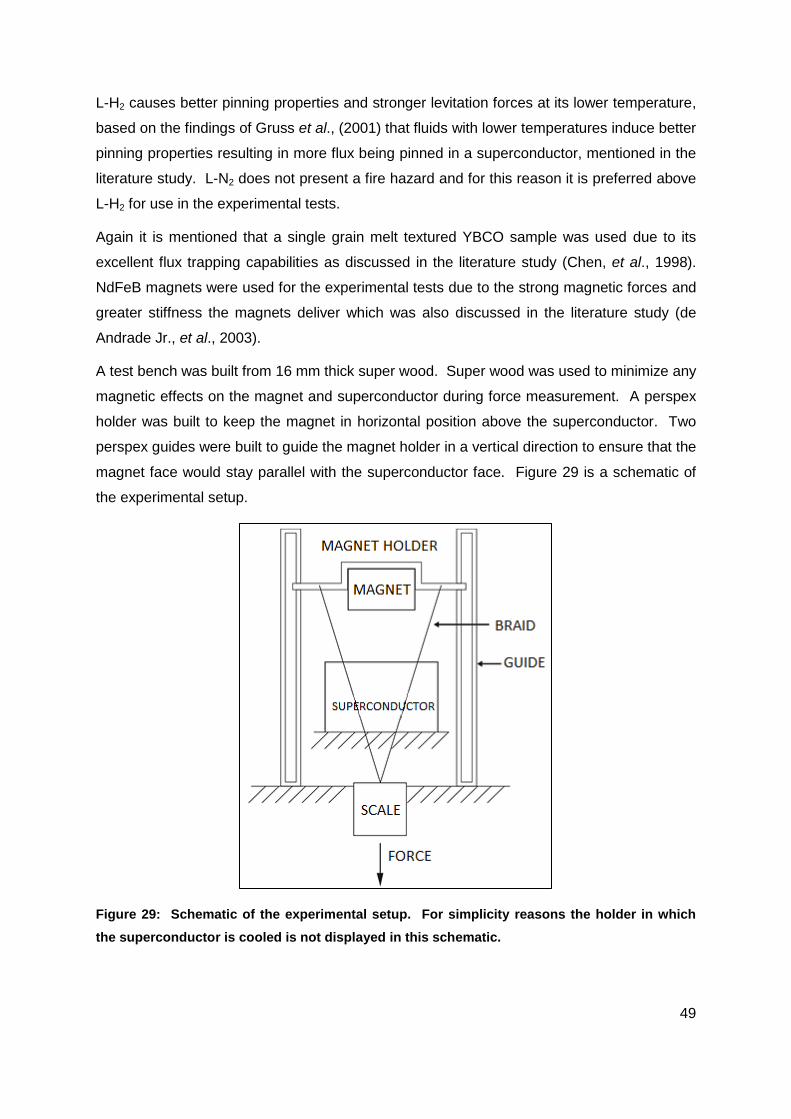
49
L-H2 causes better pinning properties and stronger levitation forces at its lower temperature,
based on the findings of Gruss et al., (2001) that fluids with lower temperatures induce better
pinning properties resulting in more flux being pinned in a superconductor, mentioned in the
literature study. L-N2 does not present a fire hazard and for this reason it is preferred above
L-H2 for use in the experimental tests.
Again it is mentioned that a single grain melt textured YBCO sample was used due to its
excellent flux trapping capabilities as discussed in the literature study (Chen, et al., 1998).
NdFeB magnets were used for the experimental tests due to the strong magnetic forces and
greater stiffness the magnets deliver which was also discussed in the literature study (de
Andrade Jr., et al., 2003).
A test bench was built from 16 mm thick super wood. Super wood was used to minimize any
magnetic effects on the magnet and superconductor during force measurement. A perspex
holder was built to keep the magnet in horizontal position above the superconductor. Two
perspex guides were built to guide the magnet holder in a vertical direction to ensure that the
magnet face would stay parallel with the superconductor face. Figure 29 is a schematic of
the experimental setup.
Figure 29: Schematic of the experimental setup. For simplicity reasons the holder in which
the superconductor is cooled is not displayed in this schematic.

50
Woven Dyneema braid (elongation < 3.5 %) was attached to the magnet holder at one end
and at the other end to an electronic scale (maximum weight limit of 40 kg), which was used
to measure the forces between the magnet and superconductor.
The superconductor was placed in an aluminium holder in which liquid nitrogen was poured.
A 10 mm thick perspex beam was placed on top of the superconductor while the magnet
was placed on the perspex beam.
To ensure temperature equilibrium between the superconductor and the holder, the holder
was filled with liquid nitrogen nearly covering the superconductor. The superconductor was
left in the holder for ample time to cool and achieve the strongest possible trapped field and
levitation force at liquid nitrogen temperature (77 K or -196.15 °C).
Once the liquid nitrogen stopped boiling around the superconductor and in the container, the
superconductor and container had reached equilibrium. This was the sign that flux trapping
had finished taking place while field cooling the superconductor. Figure 30 is a schematic of
the magnet (labelled PM) at initial condition where the air gap is 10 mm and F = 0 N
between the superconductor (below Tc) and magnet. The flux lines are pinned in the
superconductor.
Figure 30: Schematic of the field lines of the neodymium magnet pinning in the YBCO
superconductor at an air gap of 10 mm.
The magnetic field was pinned in the superconductor with the magnet stably levitating above
the YBCO sample at 10 mm. Figure 31 is a picture of a magnet in the magnet holder
levitating above the superconductor. Once flux trapping had taken place, the measurements
of reaction force on the magnet were taken.
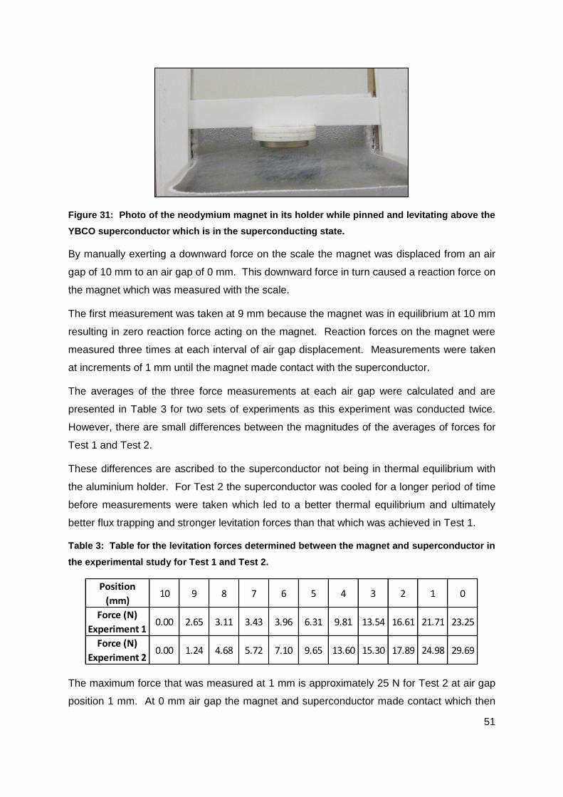
51
Figure 31: Photo of the neodymium magnet in its holder while pinned and levitating above the
YBCO superconductor which is in the superconducting state.
By manually exerting a downward force on the scale the magnet was displaced from an air
gap of 10 mm to an air gap of 0 mm. This downward force in turn caused a reaction force on
the magnet which was measured with the scale.
The first measurement was taken at 9 mm because the magnet was in equilibrium at 10 mm
resulting in zero reaction force acting on the magnet. Reaction forces on the magnet were
measured three times at each interval of air gap displacement. Measurements were taken
at increments of 1 mm until the magnet made contact with the superconductor.
The averages of the three force measurements at each air gap were calculated and are
presented in Table 3 for two sets of experiments as this experiment was conducted twice.
However, there are small differences between the magnitudes of the averages of forces for
Test 1 and Test 2.
These differences are ascribed to the superconductor not being in thermal equilibrium with
the aluminium holder. For Test 2 the superconductor was cooled for a longer period of time
before measurements were taken which led to a better thermal equilibrium and ultimately
better flux trapping and stronger levitation forces than that which was achieved in Test 1.
Table 3: Table for the levitation forces determined between the magnet and superconductor in
the experimental study for Test 1 and Test 2.
The maximum force that was measured at 1 mm is approximately 25 N for Test 2 at air gap
position 1 mm. At 0 mm air gap the magnet and superconductor made contact which then
Position
(mm)10 9 8 7 6 5 4 3 2 1 0
Force (N)
Experiment 10.00 2.65 3.11 3.43 3.96 6.31 9.81 13.54 16.61 21.71 23.25
Force (N)
Experiment 20.00 1.24 4.68 5.72 7.10 9.65 13.60 15.30 17.89 24.98 29.69

52
created a thermal conduction path defeating the purpose of superconducting levitation as
suspension mechanism. For this reason Figure 32 presents the graphs for the average
forces presented only from 1 mm to 10 mm air gap. At 10 mm the magnet levitated above
the superconductor in equilibrium.
Figure 32: Graph of the two tests conducted for the forces measured between a magnet and
superconductor at specific air gap increments.
4.2.2 Discussion
The experimental results are compared to the results obtained during the finite element- and
mathematical studies. Figure 33 is a graph of levitation force as a function of air gap, for the
forces measured experimentally and determined by calculation and simulation, between a 22
mm diameter neodymium magnet and a 45 mm diameter YBCO superconductor.
0.00
5.00
10.00
15.00
20.00
25.00
0246810
Forc
e (
N)
Air gap (mm)
Force (N)Experiment 1
Force (N)Experiment 2

53
Figure 33: Graph of levitation force as a function of air gap, measured experimentally and
determined by calculation and simulation, between a neodymium magnet and a
superconductor.
The form of the graph of levitation forces calculated with the equation derived by Fedda et
al., (2007) (labelled “Calculation”) is a flat line with a spike as it nears 0 mm in Figure 33.
From the literature survey, graphs of levitation force versus air gap were found to have
increases in levitation force with decreases in the air gap as the air gap neared 0 mm
(Fuchs, et al., 2005). The forms of these graphs of Fuchs, et al. (2005) were equal to the
forms of graphs for quadratic equations.
It is believed that the discrepancy in the graph form is due to the force being calculated in
the limit (see Equation 17). Equation 17 does not consider the outer diameter of
the superconductor in the formula. Hence the formula becomes an infinite superconducting
plane and is no longer a disk. This means that the magnetic dipole is infinitely smaller than
the superconductor.
Although Fedda et al. (2007) found that for small magnets Equation 17 delivered results
matching those of experimental tests conducted by Ma et al. (2001), it is concluded that this
model is not valid for use to determine the forces between the magnets and superconductors
of this study. It is believed that the magnets of this study are too large in comparison to the
size of the superconductors.
The results obtained in the FE studies and those of the experiments, for the levitation forces
between the magnet and superconductor did not match. The levitation forces measured in
0.00
50.00
100.00
150.00
200.00
250.00
300.00
350.00
400.00
0246810
Forc
e (
N)
Air gap (mm)
Experiment 1Experiment 2SimulationCalculation

54
the experiments were much weaker than the magnitudes of forces obtained in the
calculations and FE studies as presented in Figure 33.
An investigation into this discrepancy proved that the magnet had weaker magnetic
properties than specified by the manufacturer. The residual induction was given as Br = 1.2
T, but it was measured with a magnetometer to be Br = 0.62 T.
The coercive force was given as Hc = 860 kA/m and could not be measured due to
instrumentation shortcomings. However, using data sheets given by the supplier of a range
NdFeB magnets and the measured Br value, it was calculated by extrapolation that Hc =
440.4 kA/m.
The new magnetic properties were then introduced into the FE simulation which generated
new results for the forces between the magnet and superconductor. The forces of the
superconductor and permanent magnet as well as the sum of forces are plotted in Figure 34
as a function of air gap.
Figure 34: The graph for levitation forces acting on the superconductor, magnet and the sums
of forces as a function of air gap interval, obtained from simulations for the measured
magnetic properties of the magnet.
Table 4 lists the new results obtained in the finite element study for forces between a magnet
and a superconductor using the measured Br and calculated Hc values of the permanent
magnet in the simulations.
-40.00
-30.00
-20.00
-10.00
0.00
10.00
20.00
30.00
40.00
024681012 Forc
e (
N)
Air gap (mm)
Force (N)PM
Force (N)YBCO
Force (N)SUM

55
Table 4: Table for the forces determined in the simulation acting on the magnet and
superconductor and the sums of forces as a function of air gap position for the measured
magnetic properties of the magnet.
The results obtained in the finite element studies in which the measured magnetic properties
of the magnets were used, are compared to the test results obtained during experimental
studies for the forces between the magnet and superconductor. The values for the levitation
force on the magnet are now in good agreement with those of the experimental tests. These
forces are plotted as a function of air gap in Figure 35.
Figure 35: Graph of levitation forces between the superconductor and magnet as a function of
air gap interval obtained during experiments and simulations for the measured magnetic
properties of the magnet.
The discrepancies between the experimental results and simulation results are ascribed to
the temperatures at which the superconductor was while measurements were taken during
experiments. It was mentioned in the literature survey that field pinning is reliant on the
superconductor temperature. The colder the temperature of the superconductor is, the
Position
(mm)10 9 8 7 6 5 4 3 2 1 0
Force (N)
PM1.41 2.72 3.12 3.99 5.33 7.54 9.40 14.26 19.58 29.26 1.12
Force (N)
YBCO-2.57 -2.84 -3.52 -4.55 -5.79 -7.81 -10.51 -14.59 -20.06 -29.02 -18.86
Force (N)
SUM-1.16 -0.12 -0.41 -0.56 -0.46 -0.27 -1.11 -0.33 -0.48 0.24 -17.75
0.00
5.00
10.00
15.00
20.00
25.00
30.00
0246810
Forc
e (
N)
Air gap (mm)
Experiment 1
Experiment 2
Simulation

56
better the pinning properties of the superconductor are. Therefore stronger relationship
between the results for the experimental tests should be possible at colder temperatures.
To ensure that the superconductor temperature stayed below its Tc, liquid nitrogen was
added to the superconductor holder between measurements. The addition of L-N2 ensured
that the superconductor stayed in the superconducting state (µr = 0) throughout experimental
tests.
For the simulations magnetic field penetrated the superconductor but it was not pinned,
because µr = 0.001. Although ANSYS couldn’t solve for µr = 0, the results generated give a
good indication of the force between a magnet and a superconductor because the results of
levitation force gathered from the simulations are near to those in magnitude of the physical
experiments.
Based on these findings, it is concluded that ANSYS may be used in future studies to
determine approximate levitation forces between a magnet and a superconductor if the
correct magnetic properties and data are provided by the supplier. The experimental results
validated the results obtained during finite element modelling and simulations for force
between a magnet and superconductor in the superconducting state.
4.2.3 Conclusion and recommendations
The magnetic suspension concept presented and discussed in Chapter 3 for suspension by
means of superconducting levitation makes use of three permanent magnet-and-
superconductor pairs to deliver the required superconducting levitation force to suspend the
inner vessel within the outer vessel.
However the three magnet-and-superconductor pairs produced a maximum force of 25 N
per magnet-and-superconductor pair at 1 mm air gap (Test 2). The total sum force of these
three magnet-and-superconductor pairs at 1 mm is 75 N which is less than the 610 N force
required to levitate the inner vessel. It is calculated that approximately 24 pairs of these
magnet-and-superconductor pairs are required to produce the levitation force of 610 N at an
air gap of 1 mm.
However a levitation gap of 1 mm is not possible as the inner vessel wall and inner vessel
support rings have a combined thickness of 6 mm and the magnet caps have a thickness of
1 mm. As mentioned there is only a 3 mm gap between the inner vessel wall and magnet
support rings (see Figure 23). At 6 mm levitation gap the inner vessel rests on the magnet
caps creating a conduction path which is unwanted. Therefore the inner vessel may not
57
move to a position of less than 7 mm levitation gap between the magnet and
superconductor.
The largest levitation force that was obtained experimentally at 7 mm levitation gap is
approximately 5.7 N during Test 2. To produce a levitation force of 610 N approximately 107
magnet-and-superconductor pairs are required. The 107 magnet-and-superconductor pairs
in turn require the addition of more support rings in which the superconductors can be
mounted. The addition of more support rings increases the inner vessel weight giving rise to
the requirement of more magnet-and-superconductor pairs.
It is the conclusion of this study that for the current design, the forces between the magnets
and superconductors are not able to achieve the required forces for magnetic suspension of
the inner vessel by means of superconducting levitation at a levitation gap of 7 mm due to
the shortcomings of the obtained magnet and superconductor materials. This conclusion is
based on the findings in the latest simulation results and the results obtained experimentally
for the forces between a magnet and superconductor.
However it is believed that the use of forces generated between NdFeB magnets and bulk
superconductors is feasible for inner vessel suspension in cryogenic pressure vessels if the
magnitudes of these forces are improved.
Recommended methods to improve levitation forces of the superconductor and specifically
the forces at 7 mm air gap for the suspension concept of this design, include the use of
superconductors that have been doped with silver and zinc or that have undergone neutron
irradiation which was discussed in the literature study and to use stronger NdFeB magnets
such as N55 grade neodymium magnets (Fuchs, et al., 2005; Gruss, et al., 2001; Fuchs, et
al., 2003).
It is also suggested that the inner vessel support frame be manufactured from a different
material such as Aluminium 5083 which has a density of 2660 kg/m3 and is much less dense
than Ti-5Al-2.5Sn which has a density of 4480 kg/m3. This will lower the frame mass and
ultimately reduce required levitation forces. By lowering the internal storage pressure the
internal vessel wall thickness may also be reduced, lowering the mass of the inner vessel
and also producing a larger gap between the inner vessel wall and magnet caps.
As discussed in the preceding paragraphs it is clear that the purpose of the study was met
as a concept for the storage of liquid hydrogen was proposed and validated on the basis of
results obtained experimentally and by finite element analyses for the magnitude of levitation
forces between an YBCO disk and NdFeB magnet. However it is believed that the proposed

58
recommendations should be carried out if the concept were to be investigated further for
possible future implementation.

59
Chapter 5: Bibliography
© Volkswagen, 2012. Golf Range. [Online] Available
at: http://www.vw.co.za/en/models/golf/trimlevel_overview.html
[Accessed 25 October 2012].
Aceves, S., Berry, G. & Weisberg, A. H., 2004. Lightweight cryogenic-compatible pressure
vessels for vehicular fuel storage. United States of America, Patent No. 6708502.
Aceves, S. M., Espinosa-Loza, F., Ledesma-Orozco, E., Ross, T.O., Weisberg, A.H.,
Brunner, T.C., Kircher, O., 2009. High-density automotive hydrogen storage with cryogenic
capable pressure vessels. International journal of hydrogen energy, December, Volume 35,
pp. 1219-1226.
Askeland, D. R. & Phulé, P. P., 2003. The Science and Engineering of Materials. Fourth
Edition ed. California: Brooks/Cole - Thomson Learning.
Bleuler, H. Cole, M., Keogh, P., Larsonneur, R., Maslen, E., Nordman, R., Okada, Y.,
Schweitzer, G., Traxler, A., 2009. Magnetic Bearings. s.l.:Springer.
Chen, I.-G., Hdu, J.-C. & Wu, M.-K., 2001. Calculation of Magnetic Levitation/Suspension
Force of Single Grained Y-Ba-Cu-O Superconductors. IEEE Transactions on Applied
Superconductivity, 11(1), pp. 1745-1748.
Chen, I.-G., Hsu, J.-C., Janm, G., Kuo, C.-C., Liu, H-J, Wu, M.K., 1998. Magnetic levitation
force of single grained YBCO materials. Chinese journal of physics, April, 36(2), pp. 420-
427.
Chen, I.-G., You, L.-C., Hsu, S.-H. & Hsieh, P.-C., 2007. How superconducting levitation
works, s.l.: s.n.
Collings, E. W., 1994. Materials Properties Handbook: Titanium Alloys. 1 ed. s.l.:ASM
International.
de Andrade Jr., R., Cardoso, J. A. A. S., dos Santos, G. C., de Cicco, L. B., Fernandes, A. F.
G., Rosario, M. A. Pd., Neves, M. A., de Souza, A. P., Ripper, A., da Costa, G. C., Nicolsky,
R., Stephan, R. M., 2003. Performance of Nd-Fe-B and ferrite magnets in superconducting
linear bearings with bulk YBCO. IEEE transactions on applied superconductivity, June,
13(2), pp. 2271-2274.
De Bruyn Ouboter, R., 1997. Heike Kamerlingh Onnes's Discovery of Superconductivity.
Scientific American, March.pp. 98-103.

60
Energy, U. D. o. E. -. E. E. a. R., 2011. Fuel Cell Technologies Program – Education.
[Online]
Available at:
http://www1.eere.energy.gov/hydrogenandfuelcells/education/printable_versions/basics_stor
age.html
[Accessed 2 July 2012].
Fedda, A. Y., Alqadi, M. K., Al-Khateeb, H. M. & Ayoub, N. Y., 2007. The interaction force
between a permanent magnet and a superconducting ring. IEEE Transaction on applied
superconductivity, September, 17(3), pp. 3814-3818.
Fossheim, K. & Sudboe, A., 2004. Superconductivity: Physics and Applications. s.l.:Wiley
and Sons Inc.
Fuchs, G., Krabbes, G., Muller, K.-H., Verges, P., Schultz, L., Gonzalez-Arrabal, R., Eisterer,
M., Weber, H. W., 2003. High magnetic fields in superconducting permanent magnets.
Journal of Low Temperature Physics, October, Volume 133, pp. 159-179.
Fuchs, G., Krabbes, G., Verges, P., Canders, E.-R., May, H., 2005. Superconducting
magnetic bearings for rotating machines. Dresden, s.n., pp. 115-119.
Gruss, S., Fuchs, G., Krabbes, G., Verges, P., Schatzle, P., Muller, K.-H., Fink,
J., Schulta, L., 2001. Trapped fields beyond 14 Tesla in bulk YBa2Cu3O7-δ. Applied
superconductivity, March, 11(1), pp. 3720-3723.
Hauser, A., 1997. Calculation of superconducting magnetic bearings using a commercial FE-
program (ANSYS). IEEE Transactions on magnetics, March, 33(2), pp. 1572-1575.
Iwasa, Y., 2009. Case Studies in Superconducting Magnets: Design and Operational Issues.
2nd ed. s.l.:Springer.
Jha, A. R., 1988. Superconductor Technology: Applications to Microwave, Electro-Optics,
Electrical Machines, and Propulsion Systems. 1st ed. s.l.:John Wiley & Sons Inc.
Lewin, W., 2002. 8.02 Spring 2002 Lecture 19: Vacation Special, s.l.: s.n.
Ma, K. B., Postrekhin, Y., Ye, H. & Chu, W.-K., 2001. Magnetic Interaction Force between
High-Tc Superconductor-Ring and Magnet. IEEE Transaction on applied superconductivity,
11(1), pp. 1665-1668.
MatWeb, LLC, 2012. MatWeb Material Property Data. [Online] Available at:
http://www.matweb.com/search/DataSheet.aspx?MatGUID=e2147b8f727343b0b0d51efe02
61
a6127e&ckck=1
[Accessed 3 December 2012].
Mérida, W. & Dicken, C., 2007. Measured effects of filling time and initial mass on the
temperature distribution within a hydrogen cylinder during refuelling. Journal of Power
Sources, January, Volume 165, pp. 324-336.
Murai, T., 1987. Cryogenic container. United States of America, Patent No. 4680935.
NdFeB Specialists E-Magnets UK Limited, 2011. [Online]
Available at: http://www.ndfeb-info.com/neodymium_grades.aspx
Neves, M. A., da Costa, G.C., Pereira, A.S., de Andrade Jr. R., Nicolsky, R, 2002. Mean field
Jc Estimation for levitation device simulations in the bean model using permanent magnets
and YBCO superconducting blocks. Brazilian journal of physics, September, 32(3), pp. 759-
762.
NPL Management Limited, 2012. National Physical Laboratory. [Online]
Available at: http://www.npl.co.uk/reference/faqs/what-do-high-vacuum-and-low-vacuum-
mean-(faq-pressure)
[Accessed 19 November 2012].
Perini, E., Giunchi, G., Geri, M. & Morandi, A., 2009. Experimental and Numerical
Ivestigation of the Levitation Force Between Bulk Permanent Magnet and MgB2 Disk. IEEE
Transactions on Applied Superconductivity, 19(3), pp. 2124-2128.
Clarke, R., 2011. The force produced by a magnetic field. [Online]
Available at: http://info.ee.surrey.ac.uk/Workshop/advice/coils/force.html
[Accessed October 2011].
Ramachandran, R. & Menon, R. K., 1998. An overview of industrial uses of hydrogen.
International Journal of Hydrogen Energy, 23(7), pp. 593-598.
Reed, R. P. & Golda, M., 1997. Cryogenic composite supports: a review of strap and strut
properties. Cryogenics, Volume 37, pp. 233-250.
Sable Magnetics, 2011. [Online] Available at: http://www.sabels.com/
Sakintuna, B., Lamari-Darkrim, F. & Hirscher, M., 2007. Metal hydride materials for solid
hydrogen storage: A review. International Journal of Hydrogen Energy, January, Volume 32,
pp. 1121-1140.
Schönhuber, P. & Moon, F. C., 1994. Levitation forces, stiffness and force-creep in YBCO
high-Tc superconducting thin films. Applied superconductivity, 2(7/8), pp. 523-534.
62
Silver, D. M. & Dehaas, N., 1985. Cryogenic tank support system. United States of America,
Patent No. 4496073.
Tsuchimoto, M., 2001. Shielding current model and frozen field model in analysis of
magnetic force between a bulk HTS and a magnet. Journal of Materials Processing
Technology, Issue 108, pp. 188-192.
van Vuuren, D. S., Hietkamp, S. & Benson, J., 2009. Cryogenic Compressed Hydrogen
Storage. Somerset West, s.n., pp. 1-16.
Winter, C., 2009. Hydrogen energy - Abundant, efficient, clean: A debate over the energy-
system-of-change. International Journal of Hydrogen Energy, Volume 34, pp. S1-S52.
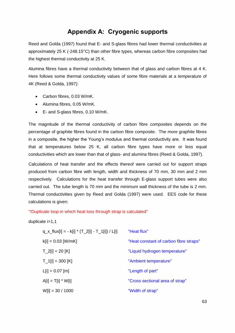
63
Appendix A: Cryogenic supports
Reed and Golda (1997) found that E- and S-glass fibres had lower thermal conductivities at
approximately 25 K (-248.15°C) than other fibre types, whereas carbon fibre composites had
the highest thermal conductivity at 25 K.
Alumina fibres have a thermal conductivity between that of glass and carbon fibres at 4 K.
Here follows some thermal conductivity values of some fibre materials at a temperature of
4K (Reed & Golda, 1997):
Carbon fibres, 0.03 W/mK.
Alumina fibres, 0.05 W/mK.
E- and S-glass fibres, 0.10 W/mK.
The magnitude of the thermal conductivity of carbon fibre composites depends on the
percentage of graphite fibres found in the carbon fibre composite. The more graphite fibres
in a composite, the higher the Young’s modulus and thermal conductivity are. It was found
that at temperatures below 25 K, all carbon fibre types have more or less equal
conductivities which are lower than that of glass- and alumina fibres (Reed & Golda, 1997).
Calculations of heat transfer and the effects thereof were carried out for support straps
produced from carbon fibre with length, width and thickness of 70 mm, 30 mm and 2 mm
respectively. Calculations for the heat transfer through E-glass support tubes were also
carried out. The tube length is 70 mm and the minimum wall thickness of the tube is 2 mm.
Thermal conductivities given by Reed and Golda (1997) were used. EES code for these
calculations is given:
"!Duplicate loop in which heat loss through strap is calculated"
duplicate i=1,1
q_x_flux[i] = - k[i] * (T_2[i] - T_1[i]) / L[i] "Heat flux"
k[i] = 0.03 [W/mK] "Heat constant of carbon fibre straps"
T_2[i] = 20 [K] "Liquid hydrogen temperature"
T_1[i] = 300 [K] "Ambient temperature"
L[i] = 0.07 [m] "Length of part"
A[i] = T[i] * W[i] "Cross sectional area of strap"
W[i] = 30 / 1000 "Width of strap"

64
T[i] = 2 / 1000 "Thickness of strap"
h_fg[i] = 446 * 1000 "Heat value for hydrogen"
q_x_heatloss[i] = A[i] * q_x_flux[i] "Heat flow for one carbon strap"
q_x_heatloss_6[i] = q_x_heatloss[i] * 6 "Heat flow for six carbon straps"
m_dot[i] = q_x_heatloss[i] / h_fg[i] "Mass loss of H2 per second per strap"
m_dot_24[i] = m_dot[i] * 24 * 3600 "Mass loss of H2 per day per strap"
m_dot_24h6[i] = m_dot_24[i] * 6 "Mass loss of H2 per day for six straps"
end
"!Duplicate loop in which heat loss through tube is calculated”
duplicate i=2,2
q_x_flux[i] = -k[i] * (T_2[i] - T_1[i]) / L[i] "Heat flux"
k[i] = 16 * 0.24 / 73 + 0.06 "Heat constant of E-glass tube"
T_2[i] = 20 "Liquid hydrogen temperature"
T_1[i] = 300 "Ambient temperature"
L[i] = 0.07 "Length of part"
A[i] = pi*(T[i])^2 "Cross sectional area of tube"
r_i[i] = 0.013 "Inner diameter of tube wall"
T[i] = r_o[i] - r_i[i] "Tube wall thickness"
r_o[i] = 0.001 + r_i[i] "Outer diameter of tube wall"
h_fg[i] = 446 * 1000 "Heat value for hydrogen"
q_x_heatloss[i] = A[i] * q_x_flux[i] "Heat loss for one E-glass strut"
q_x_heatloss_6[i] = q_x_heatloss[i] * 6 "Heat loss for six E-glass struts"
m_dot[i] = q_x_heatloss[i] / h_fg[i] "Mass loss of H2 per second per tube"
m_dot_24[i] = m_dot[i] * 24 * 3600 "Mass loss of H2 per day per tube"
m_dot_24h6[i] = m_dot_24[i] * 6 "Mass loss of H2 per day for six tubes"
end

65
Table 5 lists the results obtained solving the EES code given for determination of heat flow
through the carbon and E-glass supports. The heat addition to hydrogen through the straps,
as well as the loss of hydrogen due to boil-off, is given for one strap and six straps in row
one. These values are also given for one tube and six tubes in row 2. The flux value shows
the value of heat conducted through these supports over the support cross-sectional area.
Table 5: Results listed for calculations of heat flow through straps and tubes and hydrogen
boil off due to heat flow through supports.

66
Appendix B: Hydrogen vessel calculations
The EES code used to calculate the required mass of hydrogen and required container size
for storage of liquid hydrogen is presented below. The magnet size to produce levitation
forces to suspend an inner vessel filled with L-H2 within an outer vessel is also given in the
code.
E_specific = 119930000 [J/kg] "Specific energy"
rho_H2 = Density(Hydrogen,T=20,x=0) "Liquid hydrogen density"
m_H2 = E / E_specific "Hydrogen mass"
V_H2 = m_H2 / rho_H2 "Hydrogen volume"
"!Container properties"
V_H2 = pi * r^2 * l + 4 * pi * r^3 / 3 "Inner radius calculated"
t = 0.004[m] "Vessel Wall Thickness"
l = 0.55 "Cylinder length"
L_tot = 2 * r +l + 2 * t "Total length of the inner vessel"
m_container = (pi*(r+t)^2*l+4*pi*(r+t)^3 / 3 - V_H2 ) * rho_container "Mass container"
V_container = (pi*(r+t)^2*l+4*pi*(r+t)^3 / 3) "Container volume"
rho_container = 4480 [kg/m^3] "Density of Ti-5Al-2.5Sn ELI"
sigma_u = 775 [MPa] "Ult. tensile strength Ti-5Al-2.5Sn ELI"
sigma_y = 720 [MPa] "Ult. yield strength of Ti-5Al-2.5Sn ELI"
P = 10 [MPa] "Internal pressure of vessel"
sigma_1 = P * r / t "Stress"
sigma_2 = P * r / (2 * t) "Stress"
sigma_3 = P * r / (2 * t) "Stress"
SF = sigma_y / sigma_1 "Safety factor"
m_total = m_container + m_H2 + m_support + m_sc "Mass of container and L-H2"
m_support = 13 "Mass of support frame"
m_sc =2.5 "Mass of superconductor"
g = 9.81 [m/s^2] "Gravity constant"

67
F_total = m_total * g "Weight of filled container under gravity"
"!Permanent magnet"
F_total = B_pm^2 * A_pmbig / (2 * mu_0) "Area of permanent magnet calculated"
B_pm = 1.24[T] "Inductance"
A_pmbig = pi*r_pmbig^2 "Radius of large PM calculated"
d_pmbig = r_pmbig * 2 "Diameter of large PM calculated"
F_pm = F_total/3 "Force of one smaller PM"
F_pm = B_pm^2 * A_pm / (2 * mu_0) "Area of one permanent magnet"
A_pm = pi*r_pm^2 "Radius of large PM calculated"
d_pm = r_pm*2 "Diameter of large PM calculated"
m_pm = F_pm / 9.81 "Mass lifted by smaller PM"
mu_0 = 4 * pi / 10000000 "Permeability of free space"
"!Electromagnet"
F_em = F_pm "Electromagnet force"
F_em = (N*I)^2 * mu_0 * A_em/(2*L_em^2) "Area of electromagnet"
N = 500 [turns] "Windings"
L_em = 0.015 [m] "Electromagnet length"
I = 14 [A] "Current"
A_em = pi * r_em^2 "Radius of electromagnet calculated"
d_em = r_em * 2 "Diameter of electromagnet calculated"
Power_em = 90000 [W] "Power required for electromagnets"
E_em = Duration_sec_em * Power_em "Energy required for electromagnets"
Duration_sec_em = 120 "Electromagnet running time"
m_H2_em = E_em / E_specific "Hydrogen consumed by electromagnet"
The results from the solution of the EES code for the calculation of the required hydrogen
mass as well as vessel size and volume are given in Figure 36. The size for three
permanent magnets as well as levitation forces that are expected from these magnets is
given in the results.

68
Figure 36: Results obtained from solution of EES code given for calculation of required
hydrogen mass, storage volume, container size and magnet size.

69
Appendix C: Superconductor calculations
EES code for the solution of Equation 17 is presented below:
F = 12*(mu_0 * (mu)^2 * t * h * B_1 * (1 + cos(theta)^2)) / (pi * B_2^4) "Force (N) between a
magnetic dipole and a superconducting ring"
B_1 = 4*h^2 + t^2 "Constant"
B_2 = -4*h^2 + t^2 "Constant"
t = 0.016 [m] "Superconductor thickness (m)"
{h = 0.0081 [m]} "Distance between SC centre and magnetic dipole"
mu = 0.001 "Magnetic moment"
theta = 0 "Magnetic moment angle"
mu_0 = 4 * pi / 10000000 "Permeability of free space"
gap = h - t/2 "Levitation gap"
g = 9.81 "Gravitational constant"
m = F / g "Levitated mass"
The results of the solution of the code is given in the parametric table below. The levitation
forces are given as a function of air gap.
Table 6: Results obtained for the solution of Equation 17 for the magnet and superconductor
of this study.

70
Appendix D: Design drawings
Table 7 lists design drawings and corresponding drawing numbers of each drawing for the
design of a cryogenic container for storage of L-H2, in which an inner vessel is suspended in
an outer vessel by means of forces generated between permanent magnets and bulk YBCO
superconductors as presented in Chapter 3.
This design also makes use of an electromagnet, for initial suspension while the
superconductors make the transition for the normal state to the superconducting state.
However a design drawing for the electromagnet and electromagnet rack discussed in
Chapter 3.1.1 is not given.
Table 7: A list of design drawings and drawing numbers for a magnetically suspended
cryogenic container, which makes use of superconductor thin films suggested as a result of
this study.
ASSEMBLIES SUB-ASSEMBLIES PARTS ITEM NO. DRAWING NO.
HYDROGEN COTAINER CONCEPT HCC
INNER VESSEL ASSEMBLY IV
INNER VESSEL CYLINDER 1 IV-1
INNER VESSEL END CAP 2 IV-2
INNER VESSEL INLET END CAP 3 IV-3
INNER VESSEL SUPPORT RING 4 IV-4
INNER VESSEL SUPPORT FRAME BEAM 5 IV-5
INNER VESSEL HALF RING 6 IV-6
INNER VESSEL INLET HALF RING 7 IV-7
SUPERCONDUCTOR 8 -
SUPERCONDUCTOR CAP 9 IV-8
INNER VESSEL SUPPORT FRAME IV-9
OUTER VESSEL ASSEMBLY OV
OUTER VESSEL CYLINDER 10 OV-1
OUTER VESSEL END CAP 11 OV-2
OUTER VESSEL INLET END CAP 12 OV-3
OUTER VESSEL SUPPORT RING 13 OV-4
OUTER VESSEL SUPPORT FRAME BEAM 14 OV-5
OUTER VESSEL HALF RING 15 OV-6
OUTER VESSEL INLET HALF RING 16 OV-7
PERMANENT MAGNET 17 -
MAGNET CAP 18 OV-8
OUTER VESSEL SUPPORT FRAME OV-9
DRAWING CONTENTS