Embed Size (px)
Citation preview

Magnetic incremental encoderGEL 260for harsh industrial environments
Technical information Issued 11-2016
... automates motion.
LENORD+BAUER
Subject to technical modifications and typographical errors.
Internet: www.lenord.comE-Mail: [email protected]
Phone: +49 208 9963–0Fax: +49 208 676292
Lenord, Bauer & Co. GmbHDohlenstraße 3246145 Oberhausen, GermanyD
S22
-260
GEL 260
GEL 260 EEx
General information
High-resolution magnetic incremental encoder withrobust mechanical design.
Worldwide proven technology in various applications,suitable for harsh industrial environments.
Radial or axial plug or cable outlet avaiable. Optionally with explosion-proof housing available,
protection class IP 54 and ATEX certification. High reliability and long service life characterizes the
magnetic incremental encoders.
Features
High resolution up to 273408 pulses per revolution Interpolation up to 1024-fold Additionally current output
0 to 20 mA, 4 to 20 mA, -20 to + 20 mA Reference signal High electromagnetic compatibility (EMC)
Advantages
Absolute operational reliability even in case of highhumidity (dewing) and frequent change of ambienttemperature
Withstands extreme impacts and vibration Resistant to dirt, humidity and oil No ageing of the magnetic sensor technology
Fields of application
Heavy industry Paper-making and packaging machines Filling machines Transport and storage systems Machines for processing steel, wood, stone, plastics,
etc.
Description
2 DS22-260 / (11-2016)
Construction and design
The magnetic incremental encoder GEL 260 is based oncontactless magnetic scanning of the integrated toothedmeasuring wheel. The resilent encoder housing with aflange size of 90 mm is available with axial or radial plug orcable outlet. The solid encoder shaft is mounted to thedriving shaft via a flexible coupling. Diameter and lengthsof the encoder shaft are selectable.Optional designs include a condensate outlet or additionalprotection measures against moisture and vibration forharsh environmental conditions. Encoders with condensatedrain must be mounted so that the condesate outlet pointsdown.For usage in areas with EEx risk, the GEL 260 is availablewith ATEX approval. The flameproof housing has a flangesize of 115 mm. This variant meets protection class IP 54.Please note the changes in technical data and therestricted type code.
Sensing principle
The rotary encoders GEL 260 work with differential,magnetic-field-dependent sensors and a precision targetwheel. The sensors scan without contact the toothstructure of the target wheel and output a sine and cosinevoltage. The integrated evaluation electronics converts theanalog sensor signals into incremental output signals.
Output signals
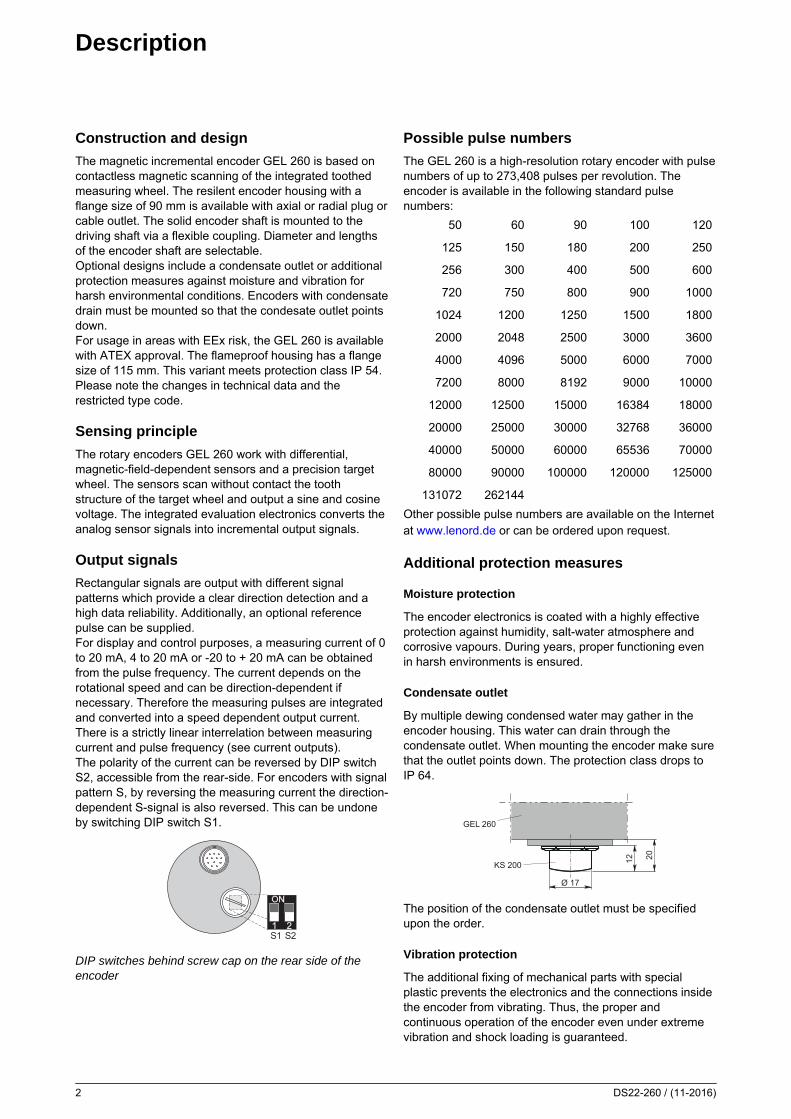
Rectangular signals are output with different signalpatterns which provide a clear direction detection and ahigh data reliability. Additionally, an optional referencepulse can be supplied.For display and control purposes, a measuring current of 0to 20 mA, 4 to 20 mA or -20 to + 20 mA can be obtainedfrom the pulse frequency. The current depends on therotational speed and can be direction-dependent ifnecessary. Therefore the measuring pulses are integratedand converted into a speed dependent output current.There is a strictly linear interrelation between measuringcurrent and pulse frequency (see current outputs).The polarity of the current can be reversed by DIP switchS2, accessible from the rear-side. For encoders with signalpattern S, by reversing the measuring current the direction-dependent S-signal is also reversed. This can be undoneby switching DIP switch S1.
S1 S2
DIP switches behind screw cap on the rear side of theencoder
Possible pulse numbers
The GEL 260 is a high-resolution rotary encoder with pulsenumbers of up to 273,408 pulses per revolution. Theencoder is available in the following standard pulsenumbers:
50 60 90 100 120
125 150 180 200 250
256 300 400 500 600
720 750 800 900 1000
1024 1200 1250 1500 1800
2000 2048 2500 3000 3600
4000 4096 5000 6000 7000
7200 8000 8192 9000 10000
12000 12500 15000 16384 18000
20000 25000 30000 32768 36000
40000 50000 60000 65536 70000
80000 90000 100000 120000 125000
131072 262144
Other possible pulse numbers are available on the Internetat www.lenord.de or can be ordered upon request.
Additional protection measures
Moisture protection
The encoder electronics is coated with a highly effectiveprotection against humidity, salt-water atmosphere andcorrosive vapours. During years, proper functioning evenin harsh environments is ensured.
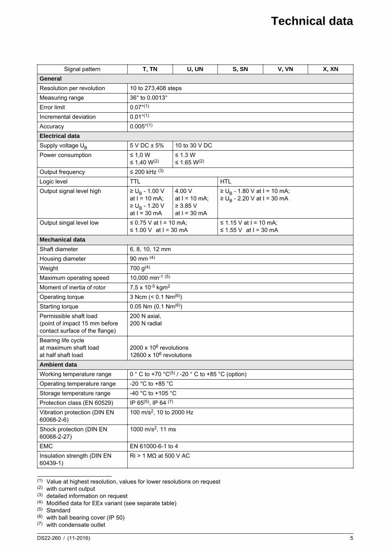
Condensate outlet
By multiple dewing condensed water may gather in theencoder housing. This water can drain through thecondensate outlet. When mounting the encoder make surethat the outlet points down. The protection class drops toIP 64.
20
Ø 17
12KS 200
GEL 260
The position of the condensate outlet must be specifiedupon the order.
Vibration protection
The additional fixing of mechanical parts with specialplastic prevents the electronics and the connections insidethe encoder from vibrating. Thus, the proper andcontinuous operation of the encoder even under extremevibration and shock loading is guaranteed.

Current outputs
DS22-260 / (11-2016) 3
Current output – options
I
nA:Direction dependent measuring currentnominal range: -20 to + 20 mA(reversible)
I
nB:Direction independent measuring currentnominal range: 0 to + 20 mA
I
nC:Direction independent measuring currentnominal range: +4 ... +20 mA.
General information
Due to the high resolution (10 to 273,408 steps direction ofrotation dependent pulses per revolution) a DC outputcurrent is obtained which shows a low harmonic contenteven at a very low speed range (e.g. 0 to 0.5 min-1). Theharmonic content depends on the pulse frequency and thedetermined attenuation, latter influencing the rising andtrailing edge times as well as the delay time in case oferratic changes of the speed.
ta
10 %
50 %
90 %
tv
t
Ia
Rise time ta and delay time tv after a erratic change inspeed
Ia Output current
Attenuation
The attenuation is adjusted according to the diagrambelow. The desired factory default setting must bespecified in the order, default is set to d3.The speed for the maximum current of 20 mA, which wasspecified in the order is indicated on the ID-plate (eg,“4000 min-1”). The attenuation is factory set so that theharmonic content p at rated speed is ≤ 1%, it is alsoindicated on the ID-plate (eg 'd5').
p [%]
f [Hz]
tatv
Harmonic content of the output current as a function of onthe pulse frequency (f) and the selectable attenuation (dn)
d attenuation
f effective pulse frequency
p harmonic content
ta rise time
tv delay time
Technical data
Current output
Max. apparent ohmic resistance Ra 550 Ω
Measuring device class K 1
Rated current tolerance < 1 %
Linearity error < 1 %
Repeatability r 100 %
Temperature drift ∆IaT < ±3 μA/1 °K
Min. RPM (for attenuation d5) nmin electrical 1,5 x 10³/i min-1
Max. RPM nmax electrical 6 x 10⁶/i min-1
i = rated pulse number

Output signals
4 DS22-260 / (11-2016)
Signal pattern V, VN
The "V" signal pattern refers to two tracks with square-wave signals offset by 90°. On the third track N a referencesignal of defined length is output once per turn.
a 360° electrical
b 90° phase offset
F Time between edges(1)
UB(2) Uout
(3)
V, VN 10 to 30 V DC HTL
Signal pattern T, TN, U, UN, X, XN
The two pulse outputs and the reference signal are outputas inverse signals.
UB(2) Uout
(3)
T, TN + 5 V DC ± 5 % TTL
U, UN 10 to 30 V DC TTL
X, XN 10 to 30 V DC HTL
Signal pattern S, SN
Pulses independent of the direction of rotation and ofconstant duration are derived from the square-wavesignals as per signal pattern V and output on the 2nd track.In addition, a signal dependent on the direction of rotationis obtained from the signal pattern (counting direction); it isoutput on the 1st track. On the third track N (option) areference signal is output once per turn.The pulses follow a possible change in the direction ofrotation with a short delay so that any downstreamcounting circuit can be set to the counting direction prior tothe pulse. The signal dependent on the direction of rotationcan be inverted using a switch accessible from the exterior(switch 1).
SSN
1
2
N
UB(2) Uout
(3)
S, SN 10 to 30 V DC HTL
Output signal level
The signal patterns S, SN, V, VN, X and XN have HTLlevels, the signal patterns T, TN, U and UN have TTLlevels. All outputs have a push-pull power amplifier andhave sustained short circuit-protection.The peak output current for discharging the cablecapacitance is 100 mA.
Maximum cable lengths
The following stated data for each signal pattern refer tocable type LiYCY 6 (10) × 0.25 mm2 between encoder andsubsequent electronics.
Maximum cable lengths
Signal patternat output frequency f of
5 10 20 50 100 200 [kHz]
T, TN, U, UN TTL (Uout = 5 V) (4) 200 200 200 200 145 72 [m]
S, SN, V, VN HTL (at Uout = 20 V) 200 200 200 80 40 20 [m]
X, XN HTL (at Uout = 20 V) 200 200 100 40 20 10 [m]
(1) At an output frequency of 200 kHz the time between the edges is F > 0.6 µs(2) Supply voltage(3) Signal voltage(4) The given lengths are only valid for a power supply with Sense control.
Technical data
DS22-260 / (11-2016) 5
Signal pattern T, TN U, UN S, SN V, VN X, XN
General
Resolution per revolution 10 to 273,408 steps
Measuring range 36° to 0.0013°
Error limit 0.07°(1)
Incremental deviation 0.01°(1)
Accuracy 0.005°(1)
Electrical data
Supply voltage UB 5 V DC ± 5% 10 to 30 V DC
Power consumption ≤ 1,0 W≤ 1,40 W(2)
≤ 1.3 W≤ 1.65 W(2)
Output frequency ≤ 200 kHz (3)
Logic level TTL HTL
Output signal level high ≥ UB - 1.00 Vat I = 10 mA;≥ UB - 1.20 Vat I = 30 mA
4.00 Vat I = 10 mA;≥ 3.85 Vat I = 30 mA
≥ UB - 1.80 V at I = 10 mA;≥ UB - 2.20 V at I = 30 mA
Output singal level low ≤ 0.75 V at I = 10 mA;≤ 1.00 V at I = 30 mA
≤ 1.15 V at I = 10 mA;≤ 1.55 V at I = 30 mA
Mechanical data
Shaft diameter 6, 8, 10, 12 mm
Housing diameter 90 mm (4)
Weight 700 g(4)
Maximum operating speed 10,000 min-1 (5)
Moment of inertia of rotor 7,5 x 10⁻⁵ kgm2
Operating torque 3 Ncm (< 0.1 Nm(6))
Starting torque 0.05 Nm (0.1 Nm(6))
Permissible shaft load(point of impact 15 mm beforecontact surface of the flange)
200 N axial,200 N radial
Bearing life cycleat maximum shaft loadat half shaft load
2000 x 106 revolutions12600 x 106 revolutions
Ambient data
Working temperature range 0 ° C to +70 °C(5) / -20 ° C to +85 °C (option)
Operating temperature range -20 °C to +85 °C
Storage temperature range -40 °C to +105 °C
Protection class (EN 60529) IP 65(5), IP 64 (7)
Vibration protection (DIN EN60068-2-6)
100 m/s2, 10 to 2000 Hz
Shock protection (DIN EN60068-2-27)
1000 m/s2, 11 ms
EMC EN 61000-6-1 to 4
Insulation strength (DIN EN60439-1)
Ri > 1 MΩ at 500 V AC
(1) Value at highest resolution, values for lower resolutions on request(2) with current output(3) detailed information on request(4) Modified data for EEx variant (see separate table)(5) Standard(6) with ball bearing cover (IP 50)(7) with condensate outlet

Connection assignment
6 DS22-260 / (11-2016)
Pin layout – plug outlet
Signal with plug outlet type Description
C / D A / B
12-pole
12
10
3
4
119
8 12
7 6
5
6-pole
E
CA
BD
F
UB 12 F Supply voltage
GND 10 A Ground
1 5 C Channel 1
/1 6 – Channel 1, inverted
2 8 B Channel 2
/2 1 – Channel 2, inverted
N 3 D Reference signal
/N 4 – Reference signal, inverted
A/B/C 7 E Current output
Usense+ 2 – + Sense (UB)(1)
Usense- 11 – - Sense (GND)
Connection assignment – cable outlet
Signal GEL 260 with outlet type GEL 260 EEx with outlet type Description
F / G H / I E K
6-core 10-core
7-core,numbered
12-core,numbered
UB yellow red 6 6 Supply voltage
GND green blue 1 1 Ground
1 brown white 3 3 Channel 1
/1 – brown – 8 Channel 1, inverted
2 white pink 2 2 Channel 2
/2 – black – 7 Channel 2, inverted
N grey violet 4 4 Reference signal
/N – yellow – 9 Reference signal, inverted
A/B/C pink grey 5 5 Current output
green 7 10, 11, 12 not connected
Cable shield not connected to sensor.
(1) If sense function is not used, use the free cores for the power supply, thus halving the voltage drop by the parallelconnection.

Dimensional drawing
DS22-260 / (11-2016) 7
Dimensional drawing GEL 260
ø50h
925
3
66302
ø 90
ø 12
h6
ø 70
M5 x 10/90°2.2
20
A
R
45°
A axial outletR radial outlet
Dimensional drawings – mating connectors
GG 66 6-pole, straight
65
ø 28
.8
GW 66 6-pole, angled
57
ø 28
.8
35
GG 126 12-pole, straight
70
ø 26
GW 126 12-pole, angled
ø 26
51
79

Dimensional drawing
8 DS22-260 / (11-2016)
Dimensional drawings – mounting accessories
Mounting bracket MW 92
3
58 7 60
90
35
7
60
42
1717
2412
7
10ø 70ø 50
22.5°
6
Mounting flange MF 121
91.5 x 45°
3
M4
ø 7
4
ø 10
.4
ø 5.
5
ø 50
ø 85
ø 12
0
ø 70
ø 100
ø 10
4
Measuring arm MA 262
MRM 500MRG 500
SP12
76
GEL 260
ø 91
ø 51
120
55.5
ø 6.1
t = 5
GLø 10
ø 10 /4.5 tief deep
20 38 97
10 2030
ø 6
ø 70
Measuring wheel MRM 500 / MRG 500with collet chuck SP 8 / 10 / 12
15-1
X
MRG 500 Operating temperature (rubber)-30 ° … +120 °C continous-40 ° … +150 °C short term

Dimensional drawing
DS22-260 / (11-2016) 9
Dimensional drawings – mounting accessories
Clamping elements KL 260 (4 pieces)
ø 10 3.9
ø 12 1.9 -0.05
ø 4.
2
1
Dimensional drawing – Coupling
Clamp coupling KK 142 identical coupling halves, positive-fit prestressed,backlash-free assembled
M3 DIN 912
3511 *)
ø 30
ø d 1
ø d 2
11 *)
A B A
22.5
5A
*) Maximum dimension for inserted shaft
A Coupling half
B Involute gear rim
d1(1) d2
(1) Standardd1 / d2
KK 14 6 … 16 6 … 16 6/6; 8/8; 10/10;12/12; 16/16
with different diameters d1 and d2 available
static torsional stiffness 125 Ncm/°
transmittable torque, backlash-free 100 Ncm
maximum misalignmentaxialradialangular
-1 mm0.2 mm1°
Metal coupling MK 8 / MK 12
AB
ø D
ø d 1
ø d 2
MK 8 Material: X12CrNi18-8 (V2-A)
MK 12 Material: ST
A B D d1(1) d2
(1)Standard
d1 / d2
MK 8 35 5 21 5 … 12 5 … 126/6; 8/8;
10/10;12/12
MK 12 50 7 26(2) 6 … 15 6 … 15 12/12
with different diameters d1 and d2 available
Permissible offset of nominal shaft diameter: 3° or 3%zulässige Fluchtungenauigkeit desNennwellendurchmessers: 3° oder 3%
Screw coupling MKF 8 / MKF 12
A
E
ø D
ø C ø d
ø B
6
1.5
M4, 90° 3 x ø 4.8
F
A B C(1) D E F d(1)Standard
d
MKF 8 30 42 18 21 5 30 6 … 10 6; 8; 10
MKF 12 40 48 22 26(2) 7 37 8 … 15 12
Permissible offset of nominal shaft diameter: 3° or 3%Mount coupling with 1 mm preload.
(1) Tolerance H7(2) with keyway avaialbe

Encoder with Ex protection
10 DS22-260 / (11-2016)
General information GEL 260 EEx
The rotary encoder GEL 260 Ex is only allowed to beoperated in zone 1. The mechanical and electricalcharacteristics as per the operating instructions GEL 260Ex, e.g. temperature, max. load current, max. supplyvoltage and mechanical load, are not allowed to beexceeded under any circumstances. The GEL 260 Ex is
only allowed to be operated with the protection classapproved. The company operating the system has theobligation to undertake a risk assessment. For theconnection only the variant with cable outlet E or Ktogether with the junction box EEx e is allowed to be used.The type code is restricted.
Type code for Ex protection
Feature Possible variant
Current outputSignal patternReference signalPulse numbers per revolution
no restrictions
Plug / cable outlet E, K
Shaft diameter / length 0
Additional protection measures 6, 7, 8, 9
Temperatur range 1
Dimensional drawing GEL 260 for Ex-hazardous areas
90°
M6x15
Ø 70
Ø 1
20Ø
90
Ø 5
0 h7
2.513.5
200
934
Ø 5
0 h7
M6x15
90°
Ø 70
Junction box EEx eNumber of terminals: 12
1 2 3 4 5 6 7 8 9
135
163
175
5280
8
21
54 4,3
PG13.5
4.3
Modified technical data of GEL 260 EEx
Mechanical data
Housing diameter 115 mm
Weight 5.1 kg
Maximum operating speed 3000 min-1
Starting torque 0.06 Nm
Safety parameters
Ignition protection type II 2G EEx [ia/ib] IIC T5-T6
Certification number PTB03ATEX1051(former PTB-Nr. Ex-87/1095)
Protection class IP 54 pressure-proof

Type code GEL 260
DS22-260 / (11-2016) 11
Current output- without current outputA Nominal range -20 mA to +20 mA (1)
B Nominal range 0 mA to +20 mA (1)
C Nominal range +4 mA to +20 mA (1)
Signal pattern- without signal outputS Signal pattern S, logic level HTLT Signal pattern T; logic level TTL (2)
U Signal pattern U; logic level TTL (2)
V Signal pattern VN; logic level HTLX Signal pattern XN; logic level HTL (2)
Reference signal– without reference signalN with Reference signal
Pulse number_ _ _ _ _ _ Pulse number per revolution
Plug / cable outletA 6-pole plug, axial(3)
B 6-pole plug, radial(3)
C 12-pole plug, axial(3)
D 12-pole plug, radial(3)
E 7-core cable(4) (only for GEL 260 EEx)F 6-core cable(4) , axialG 6-core cable(4), radialH 10-core cable(4) , axialI 10-core cable(4), radialK 12-core cable(4)(only for GEL 260 EEx)
Shaft diameter / length0 Standard; d = 12 mm, L = 30 mm
for GEL 260 EEx d = 12 mm, L = 27 mm1 d = 6 mm, L = 13 mm2 d = 8 mm, L = 30 mm3 d = 8 mm, L = 30 mm, shaft with Woodruff key to DIN 68884 d = 10 mm, L = 30 mm5 d = 10 mm, L = 30 mm, shaft with Woodruff key to DIN 68887 d = 12 mm, L = 30 mm, shaft with Woodruff key to DIN 6888
Additional protection measures0 without additional protection measures (standard)1 Moisture protection2 Vibration protection3 Moisture and vibration protection4 Moisture protection and condensate outlet (5)
5 Moisture and vibration protection with condensate outlet (5)
6 Protection class EEx without additional protection measures7 Protection class EEx with moisture protection8 Protection class EEx with vibration protection9 Protection class EEx with moisture and vibration protection
Temperature range1 0°C to +70°C3 -20°C to +85°C (extended)
260 _ _ _ _ _ _ _ _ _ _ _ _ _ Customer-specific designs
Customer-specific modifications to mechanical and electrical features are in principle possible.
(1) Nominal speed for Imax must be specified upon the order.(2) Only with plug / cable outlet option: C, D, H, I, K(3) Mating connector straight included in the scope of supply (angled mating connector available)(4) Standard cable length 1 m (other cable length must be specified upon the order)(5) Position must be specified upon the order.

Type code GEL 260
12 DS22-260 / (11-2016)
Accessories
Mounting accessories
Description Item number
Screw mount coupling MKF 8: inner diameter 6 to 10 mm(specify shaft diameter, standard: 6, 8, 10 mm)
MKF 8
Screw mount coupling MKF 12: inner diameter 8 to 15 mm(specify shaft diameter, standard: 12 mm)
MKF 12
Clamp coupling KK14, inner diameter: 6 to 16 mm (specify shaft diameter) KK 14
Clamping element (set with 4 pieces) KL 260
Metal coupling MK 8, inner diameter: 5 to 12 mm (specify shaft diameter) MK 8
Metal coupling MK 12, Innendurchmesser: 6 to 15 mm (specify shaft diameter) MK 12
Mounting bracket for encoder GEL 260, aluminium die casting MW 92
Mounting flange, aluminium die casting, diameter 120 mm MF 121
Measuring wheel, aluminium die casting, hard anodic coated surface (approx. 700 HV),circumference 500 mm ± 0.3 mm, collet chuck included
MRM 500
Measuring wheel, aluminium die casting, rubber coated surface (approx. shore 70, coating:Nitrile), circumference 500 mm ± 0.8 mm, collet chuck included
MRG 500
Collet chuck for mounting MRM 500 / MRG 500, shaft diameter 8, 10 or 12 mmSP 08/SP 10/
SP 12
Protective casing with cable glands 5 x PG21 SG 110
Protective casing with cable glands 6 x PG21 SG 111
Connection accessories
Description Item number
Mating connector, M23, 12-pole, straight, IP 65 GG 126
Mating connector, M23, 12-pole, angled, IP 65 GW 126
Mating connector, 6-pole, straight, IP 65 GG 66
Mating connector, 6-pole, angled, IP 65 GW 66
Junction box EEx, number of terminals 12 upon request
Subject to technical modifications and typographical errors.