Embed Size (px)
Citation preview
ment. The control equipment is designed
to be operated from a stronger, all-relay,
or cross-bar type of telephone office.
T w o types of mobile equipment were
used in this trial installation, one 60-watt
unit, and one 30-watt unit. Actually,
the system will work with any mobile
gear. The selector utilizes a 3-inch chassis
so as to fit into a standard 17-inch case.
I t may be externally mounted if so de-
sired. Fig. 4 shows a mobile unit with
cover removed.
Fig. 5 shows the mobile dash unit
furnished. This unit is of the cradle
design, very similar to a conventional
telephone except that it has a simple
locking device to prevent the handset
from bouncing out of the cradle on rough
terrain. This unit contains an ON-OFF
key-type switch on the side, and ON-OFF,
BUSY, and ON-AIR lamps in the upper
front. A small reverting call push
button switch is mounted on the opposite
side visible in Fig. 5. T h e dash unit con-
tains a hinged bracket which enables the
unit to be mounted on the top, front, or
bottom of the dash panel of the car. A
short cable extends from the dash unit to
a small buzzer box usually mounted
under this dash panel. This unit con-
tains the volume control, squelch control,
buzzer, and the necessary terminals to con-
nect the radio equipment to the dash unit.
The equipment in the fixed mobile
station is similar to the low-power mobile
unit except that it operates from a com-
mercial power source. T h e unit is rated
in the 15-to-25 watt class. A desk phone
is used in this application with the neces-
sary indicating lamps as shown in Fig. 6.
In place of a buzzer this unit uses a con-
ventional 60-cycle gong-type ringer. A
reverting call button is contained directly
under the handset.
Conclusions
Since the development work on this proj-
ect was started, a large amount of interest
has been shown and many new uses con-
sidered for this type of a telephone system.
There seem to be many places where it
might be used to great advantage either as
a way of offering quick temporary tele-
phone service, or in places where telephone
service does not warrent the expense of
poles and wire. Where microwave cir-
cuits can eliminate outside plant between
urban areas, so an automatic radio tele-
phone system of this type can eliminate
outside plant within the urban area.
M a g n e t i c Field Strength in O e r s t e d s
N e a r Large Rectangular Conductors
J. H. MILLER F E L L O W AIEE
A H I G H V A L U E of direct current in a
conductor produces a high mag-
netic field which may affect electro-
magnetic instruments and control gear
in the vicinity. T h e value of the mag-
netic field in oersteds at a distance d in
feet, from the center of a large round
conductor, solid or tubular, carrying a
current of J amperes is given ve ry simply
b y the equation,
#=0.006561/� ( 1 )
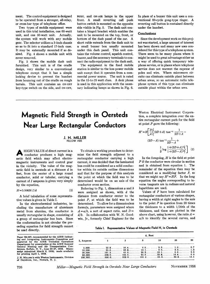
A brief tabulation of some representa-
t ive values is given in Table I .
I n the electrochemical industries, in-
cluding the manufacture of aluminum
metal from alumina, the conductor is
usually rectangular in shape, consisting of
a group of rectangular bus bars. Since
the conformation is not circular the pre-
ceding equation for field strength cannot
be used directly.
Paper 58-367, recommended by the A I E E Indicat-ing and Integrating Instruments Committee and approved by the A I E E Technical Operations Department for presentation at the A I E E Summer General Meeting and Air Transportation Con-ference, Buffalo, Ν . Y . , June 22-27, 1958. Manu-script submitted March 6, 1958; made available for printing April 1, 1958.
J. H . M I L L B R is with Weston Instruments, Division of Daystrom, Inc., Newark, N . J.
T o obtain a working procedure to deter-
mine the field strength adjacent to a
rectangular conductor carrying a high
current, it was decided that the laminated
bus could be considered as a solid conduc-
tor within its outside outline dimensions
and that for the purpose of this analysis
the point at which the field was to be
determined would be on an axis of the
conductor cross section.
Referring to Fig. 1, dimensions a and b
were assigned as shown, with d the
distance from conductor center to the
point P, at which the field was to be
determined. T o allow for a dimensionless
formula, parameters were assigned where
A=a/b, a sort of aspect ratio, and D =
d/b. In collaboration with W . N . Good-
win, Jr., formerly Chief Engineer for the
I , Amperes 1 2
5,000 32.8 16.4. 10,000 65.6 32.8. 20,000 131.2 65.6. 50,000 328.0 164.0.
100,000 656.0 328.0
Weston Electrical Instrument Corpora-
tion, a complete integration over the en-
tire rectangular current path for the field
at point Ñ gave the following:
1 1 + ( 2 Ñ + Ë ) ' Ð
In the foregoing, Ç is the field at point
Ñ if the conductor were circular in section
and is obtained from equation 1. The
remainder of the equation then may be
considered as a modifying factor F, so
that we might say H'=HF. In the long
equation the angles corresponding to in-
verse tangents are in radians and natural
logarithms are used.
Values of F have been calculated for
rectangular conductors of various shapes,
having a width at right angles to the axis
to the point Ñ in question from 20 times
the thickness to a width l /20th of the
thickness, and these are plotted in the
above chart, using however, the ratio A =
a/b to identify the several curves, and
d, Feet
5 10 20 50
6.6 . . . . 3.3 . . . . 1.6 . . . . 0.7 13.1 . . . . 6.6 . . . . 3.3 . . . . 1.3 26.2 . . . .13.1 . . . . 6.6 . . . . 2.6 65.6 . . . .32.8 . ...16.4 . . . . 6.6
131.2.. . . . . . .65.6 . . . . 3 2 . 8 . . . . . . . 13.1
T a b l e I . R e p r e s e n t a t i v e V a l u e s o f M a g n e t i c F i e l d H , i n O e r s t e d s
726 Miller—Magnetic Field Strength in Oersteds Near Large Conductors N O V E M B E R 1958
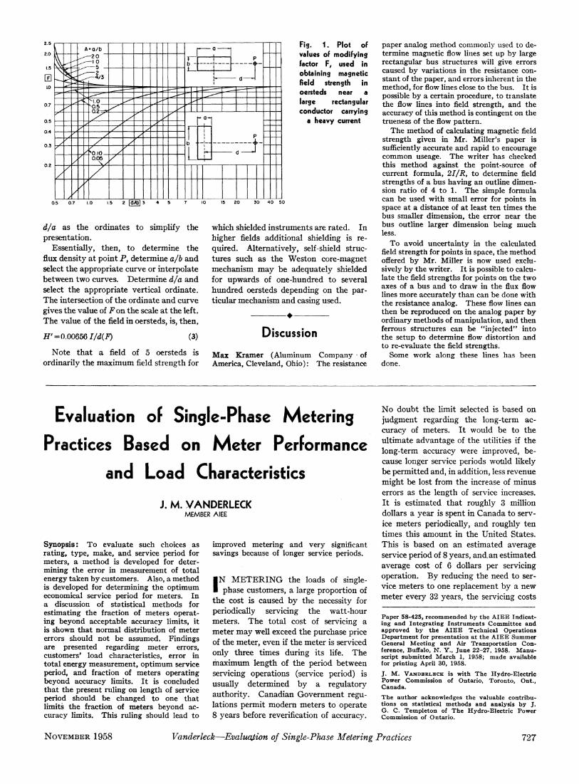
F i s - 1 . P l o t o f v a l u e s o f m o d i f y i n g f a c t o r F , u s e d i n o b t a i n i n g m a g n e t i c field s t r e n g t h i n o e r s t e d s n e a r a l a r g e r e c t a n g u l a r c o n d u c t o r c a r r y i n g
a h e a v y c u r r e n t
0.5 0.7 1.0 1.5 2 fdÂïl 3 4 5 7 30 40 50
d/a as the ordinates to simplify the
presentation.
Essentially, then, to determine the
flux density at point P , determine a/b and
select the appropriate curve or interpolate
between two curves. Determine d/a and
select the appropriate vertical ordinate.
The intersection of the ordinate and curve
gives the value of F on the scale at the left.
The value of the field in oersteds, is, then,
W = 0.006561/d(F) ( 3 )
Note that a field of 5 oersteds is
ordinarily the maximum field strength for
which shielded instruments are rated. In
higher fields additional shielding is re-
quired. Alternatively, self-shield struc-
tures such as the Weston core-magnet
mechanism may be adequately shielded
for upwards of one-hundred to several
hundred oersteds depending on the par-
ticular mechanism and casing used.
•
Discussion
Max Kramer (Aluminum Company * of America, Cleveland, Ohio): The resistance
paper analog method commonly used to de-termine magnetic flow lines set up by large rectangular bus structures will give errors caused by variations in the resistance con-stant of the paper, and errors inherent in the method, for flow lines close to the bus. I t is possible by a certain procedure, to translate the flow lines into field strength, and the accuracy of this method is contingent on the trueness of the flow pattern.
The method of calculating magnetic field strength given in Mr . Miller's paper is sufficiently accurate and rapid to encourage common useage. The writer has checked this method against the point-source of current formula, 2I/R, to determine field strengths of a bus having an outline dimen-sion ratio of 4 to 1. The simple formula can be used with small error for points in space at a distance of at least ten times the bus smaller dimension, the error near the bus outline larger dimension being much less.
T o avoid uncertainty in the calculated field strength for points in space, the method offered by Mr . Miller is now used exclu-sively by the writer. I t is possible to calcu-late the field strengths for points on the two axes of a bus and to draw in the flux flow lines more accurately than can be done with the resistance analog. These flow lines can then be reproduced on the analog paper by ordinary methods of manipulation, and then ferrous structures can be "injected" into the setup to determine flow distortion and to re-evaluate the field strengths.
Some work along these lines has been done.
Evaluation of Single-Phase M e t e r i n g
Practices Based on M e t e r Performance
and L o a d Characteristics
J. M . YANDERLECK MEMBER AIEE
S y n o p s i s : T o evaluate such choices as rating, type, make, and service period for meters, a method is developed for deter-mining the error in measurement of total energy taken by customers. Also, a method is developed for determining the optimum economical service period for meters. In a discussion of statistical methods for estimating the fraction of meters operat-ing beyond acceptable accuracy limits, it is shown that normal distribution of meter errors should not be assumed. Findings are presented regarding meter errors, customers' load characteristics, error in total energy measurement, optimum service period, and fraction of meters operating beyond accuracy limits. I t is concluded that the present ruling on length of service period should be changed to one that limits the fraction of meters beyond ac-curacy limits. This ruling should lead to
improved metering and very significant savings because of longer service periods.
IN M E T E R I N G the loads of single-
phase customers, a large proportion of
the cost is caused by the necessity for
periodically servicing the watt-hour
meters. T h e total cost of servicing a
meter may well exceed the purchase price
of the meter, even if the meter is serviced
only three times during its life. T h e
maximum length of the period between
servicing operations (service period) is
usually determined by a regulatory
authority. Canadian Government regu-
lations permit modern meters to operate
8 years before reverification of accuracy.
N o doubt the limit selected is based on
judgment regarding the long-term ac-
curacy of meters. I t would be to the
ultimate advantage of the utilities if the
long-term accuracy were improved, be-
cause longer service periods would likely
be permitted and, in addition, less revenue
might be lost from the increase of minus
errors as the length of service increases.
I t is estimated that roughly 3 million
dollars a year is spent in Canada to serv-
ice meters periodically, and roughly ten
times this amount in the United States.
This is based on an estimated average
service period of 8 years, and. an estimated
average cost of 6 dollars per servicing
operation. B y reducing the need to ser-
vice meters to one replacement by a new
meter every 32 years, the servicing costs
Paper 58-425, recommended by the AIEE Indicat-ing and Integrating Instruments Committee and approved by the AIEE Technical Operations Department for presentation at the AIEE Summer General Meeting and Air Transportation Con-ference, Buffalo, Ν . Y . , June 22-27, 1958. Manu-script submitted March 1, 1958; made available for printing April 30, 1958.
J. M . V A N D B R L B C K is with The Hydro-Electric Power Commission of Ontario, Toronto, Ont., Canada.
The author acknowledges the valuable contribu-tions on statistical methods and analysis by J. G. C. Templeton of The Hydro-Electric Power Commission of Ontario.
N O V E M B E R 1958 Vanderleck—Evaluation of Single-Phase Metering Practices 727