Embed Size (px)
Citation preview

MAE 322
Machine Design
Shafts -1 Dr. Hodge Jenkins
Mercer University

Why shafts?
Shigley’s Mechanical Engineering Design
Motors rotate
Rotational linkages from motor are the simplist
Transmit power/kinetics
Movement/kinematics
Linear shafts, used for alignment and guides, are not what is
being discussing.

Shaft Materials
Deflection primarily controlled by geometry, not material
Stress controlled by geometry, not material
Strength controlled by material property
Shigley’s Mechanical Engineering Design

Shaft Design
Material Selection (usually steel, unless you have good reasons)
Geometric Layout (fit power transmission equipment, gears,
pulleys)
Stress and strength
◦ Static strength
◦ Fatigue strength
Deflection and rigidity
◦ Bending deflection
◦ Torsional deflection
◦ Slope at bearings and shaft-supported elements
◦ Shear deflection due to transverse loading of short shafts
Vibration due to natural frequency (whirl)
Shigley’s Mechanical Engineering Design
Shaft Materials
Shafts are commonly made from low carbon, CD or HR steel,
such as AISI 1020–1050 steels.
Fatigue properties don’t usually benefit much from high alloy
content and heat treatment.
Surface hardening usually only used when the shaft is being
used as a bearing surface.
Shigley’s Mechanical Engineering Design
Shaft Materials
Cold drawn steel typical for d < 3 in.
HR steel common for larger sizes. Should be machined all over.
Low production quantities
◦ Lathe machining is typical
◦ Minimum material removal may be design goal
High production quantities
◦ Forming or casting is common
◦ Minimum material may be design goal
Shigley’s Mechanical Engineering Design
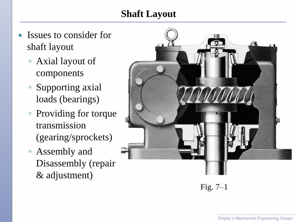
Shaft Layout
Issues to consider for
shaft layout
◦ Axial layout of
components
◦ Supporting axial
loads (bearings)
◦ Providing for torque
transmission
(gearing/sprockets)
◦ Assembly and
Disassembly (repair
& adjustment)
Shigley’s Mechanical Engineering Design
Fig. 7–1

Axial Layout of Components
Shigley’s Mechanical Engineering Design
Fig. 7–2

Supporting Axial Loads
Axial loads must be supported through a bearing to the frame.
Generally best for only one bearing to carry axial load to shoulder
Allows greater tolerances and prevents binding
Shigley’s Mechanical Engineering Design
Fig. 7–3 Fig. 7–4
Providing for Torque Transmission
Common means of transferring torque to shaft
◦ Keys
◦ Splines
◦ Setscrews
◦ Pins
◦ Press or shrink fits
◦ Tapered fits
Keys are one of the most effective
◦ Slip fit of component onto shaft for easy assembly
◦ Positive angular orientation of component
◦ Can design key to be weakest link to fail in case of overload
Shigley’s Mechanical Engineering Design
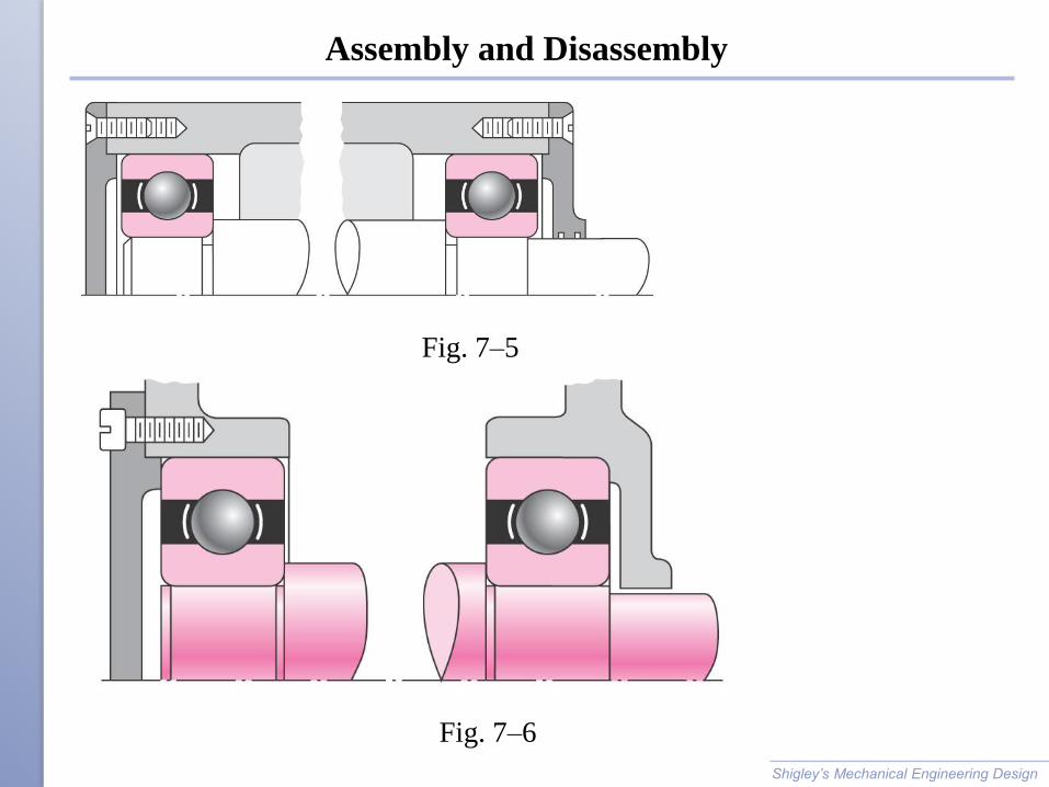
Assembly and Disassembly
Shigley’s Mechanical Engineering Design
Fig. 7–5
Fig. 7–6
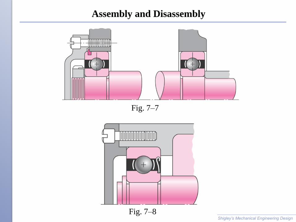
Assembly and Disassembly
Shigley’s Mechanical Engineering Design
Fig. 7–7
Fig. 7–8
Shaft Design for Stress
Stresses are only evaluated at critical locations
Critical locations are usually
◦ On the outer surface
◦ Where the bending moment is large
◦ Where the torque is present
◦ Where stress concentrations exist
Shigley’s Mechanical Engineering Design
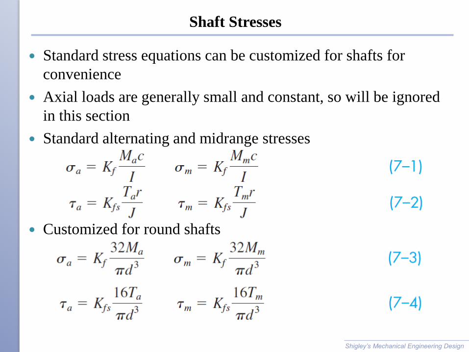
Shaft Stresses
Standard stress equations can be customized for shafts for
convenience
Axial loads are generally small and constant, so will be ignored
in this section
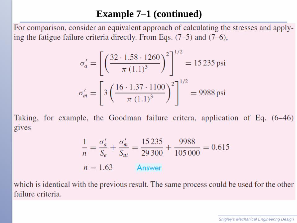
Standard alternating and midrange stresses
Customized for round shafts
Shigley’s Mechanical Engineering Design
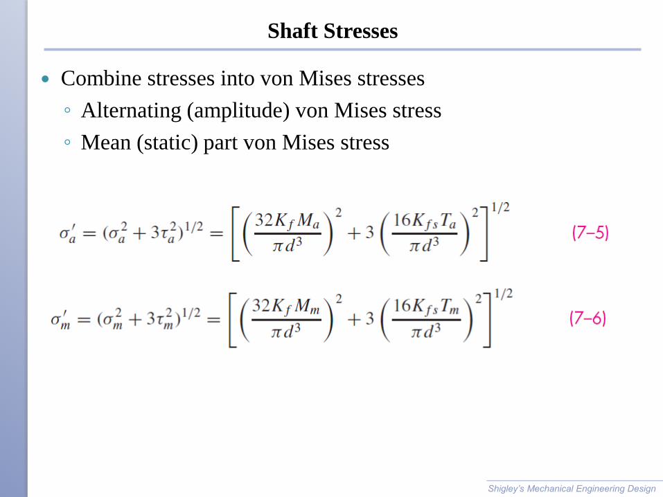
Shaft Stresses
Combine stresses into von Mises stresses
◦ Alternating (amplitude) von Mises stress
◦ Mean (static) part von Mises stress
Shigley’s Mechanical Engineering Design

Shaft Stresses
Substitute von Mises stresses into failure criteria equation. For
example, using modified Goodman line,
Solving for d is convenient for design purposes
Shigley’s Mechanical Engineering Design

Shaft Stresses
Similar approach can be taken with any of the fatigue failure
criteria
Equations are referred to by referencing both the Distortion
Energy method of combining stresses and the fatigue failure
locus name. For example, DE-Goodman, DE-Gerber, etc.
In analysis situation, can either use these customized equations
for factor of safety, or can use standard approach from Ch. 6.
In design situation, customized equations for d are much more
convenient.
Shigley’s Mechanical Engineering Design
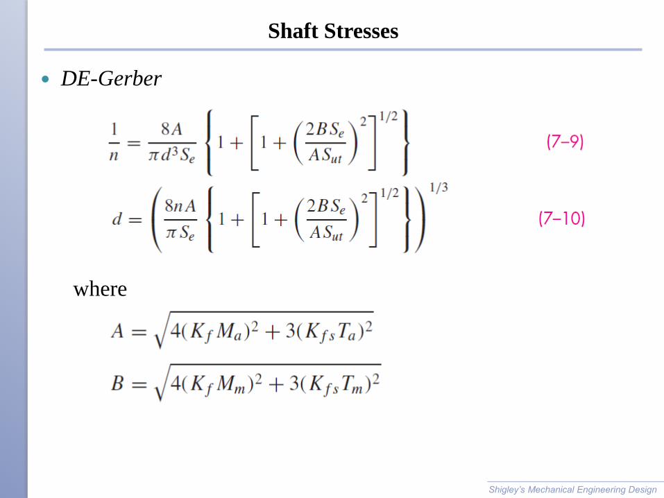
Shaft Stresses
DE-Gerber
Shigley’s Mechanical Engineering Design
where
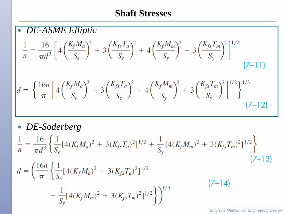
Shaft Stresses
DE-ASME Elliptic
DE-Soderberg
Shigley’s Mechanical Engineering Design
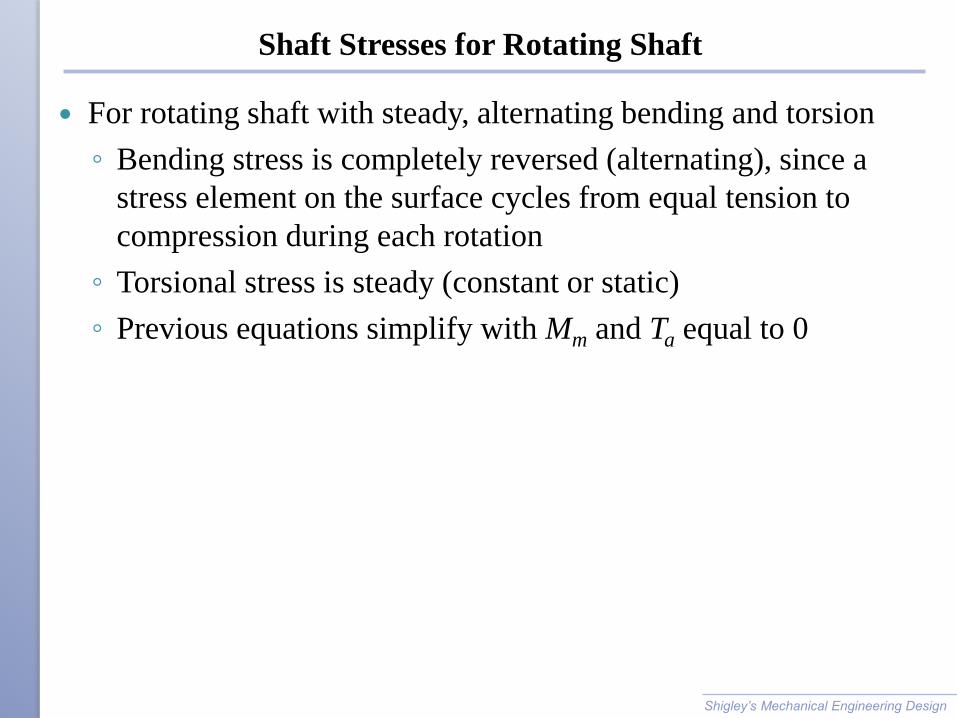
Shaft Stresses for Rotating Shaft
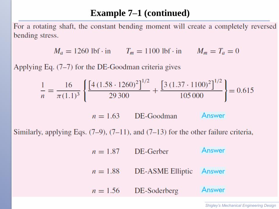
For rotating shaft with steady, alternating bending and torsion
◦ Bending stress is completely reversed (alternating), since a
stress element on the surface cycles from equal tension to
compression during each rotation
◦ Torsional stress is steady (constant or static)
◦ Previous equations simplify with Mm and Ta equal to 0
Shigley’s Mechanical Engineering Design
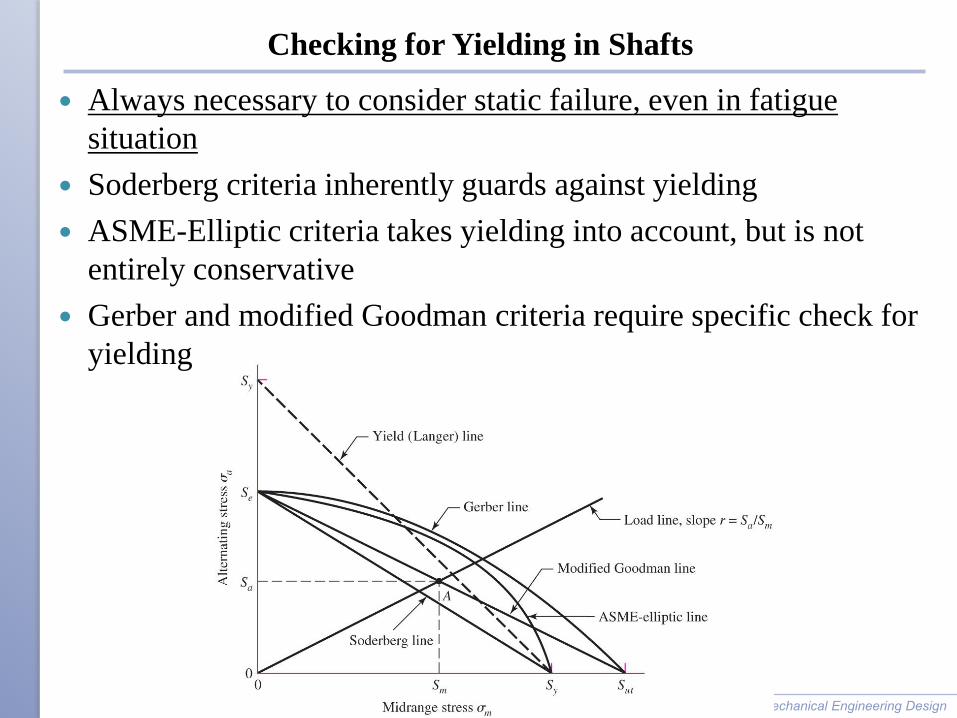
Checking for Yielding in Shafts
Always necessary to consider static failure, even in fatigue
situation
Soderberg criteria inherently guards against yielding
ASME-Elliptic criteria takes yielding into account, but is not
entirely conservative
Gerber and modified Goodman criteria require specific check for
yielding
Shigley’s Mechanical Engineering Design

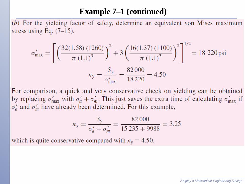
Checking for Yielding in Shafts
Use von Mises maximum stress to check for yielding,
Alternate simple check is to obtain conservative estimate of s'max
by summing s'a and s'm
Shigley’s Mechanical Engineering Design
max a ms s s
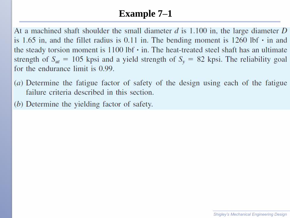
Example 7–1
Shigley’s Mechanical Engineering Design
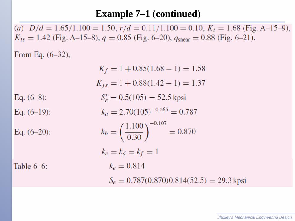
Example 7–1 (continued)
Shigley’s Mechanical Engineering Design
Example 7–1 (continued)
Shigley’s Mechanical Engineering Design
Example 7–1 (continued)
Shigley’s Mechanical Engineering Design
Example 7–1 (continued)
Shigley’s Mechanical Engineering Design

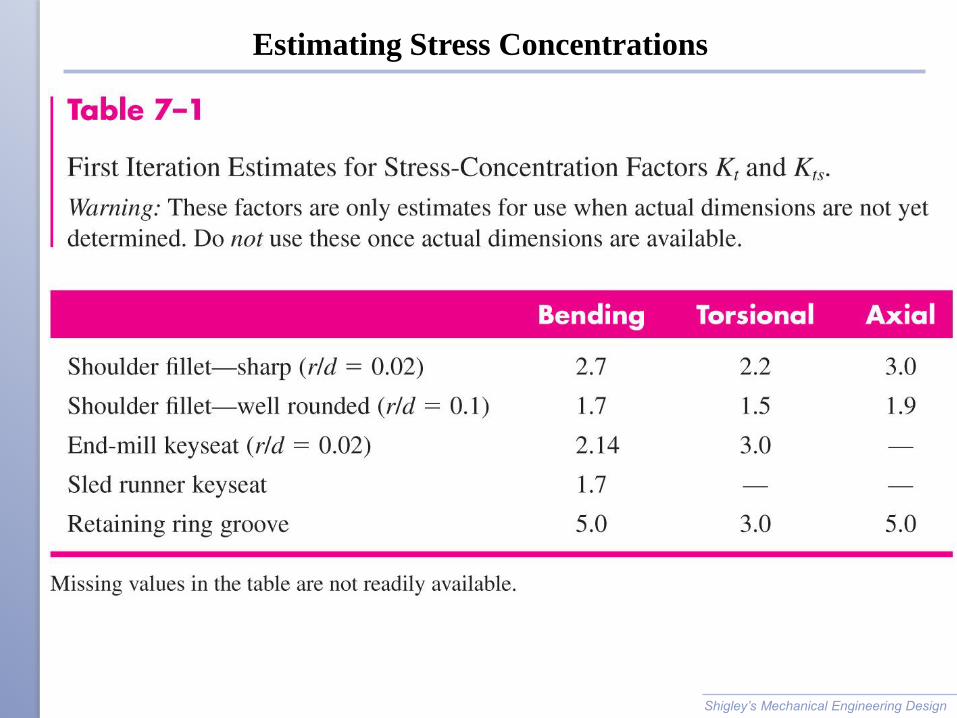
Estimating Stress Concentrations
Stress analysis for shafts is highly dependent on stress
concentrations.
Stress concentrations depend on size specifications, which are
not known the first time through a design process.
Standard shaft elements such as shoulders and keys have
standard proportions, making it possible to estimate stress
concentrations factors before determining actual sizes.
Shigley’s Mechanical Engineering Design
Estimating Stress Concentrations
Shigley’s Mechanical Engineering Design
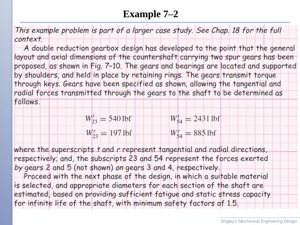
Example 7–2
Shigley’s Mechanical Engineering Design
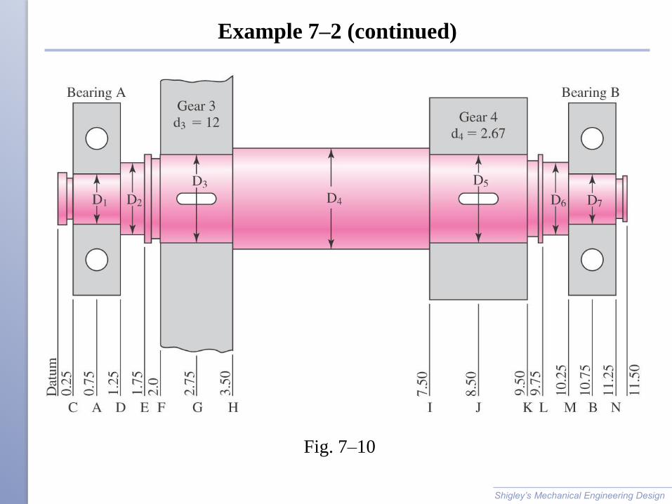
Example 7–2 (continued)
Shigley’s Mechanical Engineering Design
Fig. 7–10

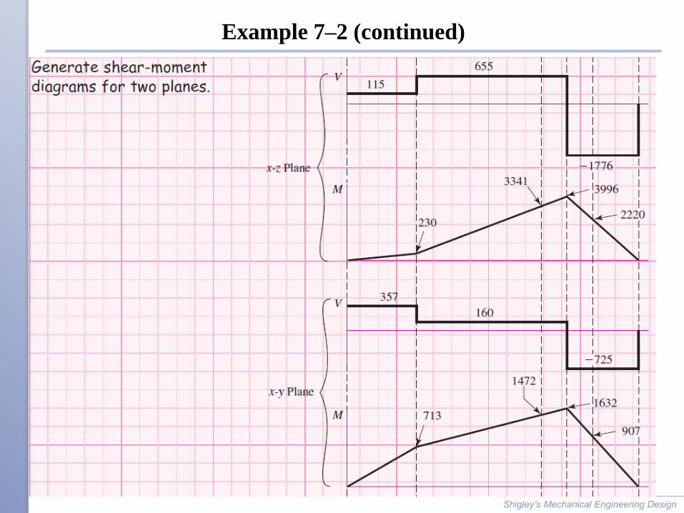
Example 7–2 (continued)
Shigley’s Mechanical Engineering Design
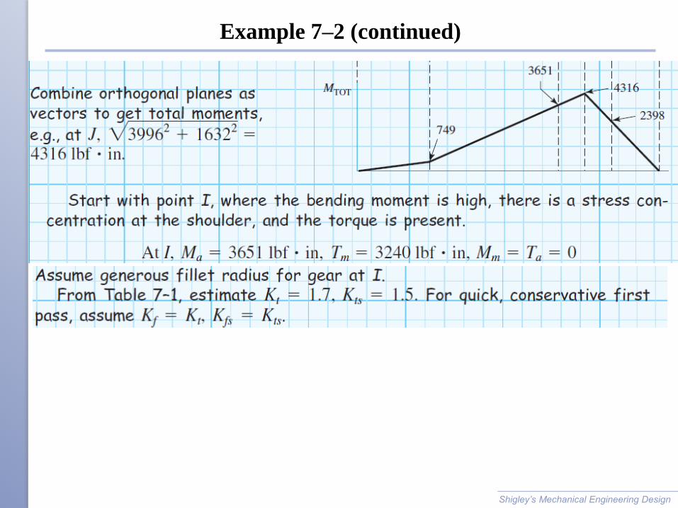
Example 7–2 (continued)
Shigley’s Mechanical Engineering Design
Example 7–2 (continued)
Shigley’s Mechanical Engineering Design

Example 7–2 (continued)
Shigley’s Mechanical Engineering Design