Embed Size (px)
Citation preview

MAE 322
Machine Design
Lecture 5
Fatigue - 4 Dr. Hodge Jenkins
Mercer University

Characterizing Fluctuating Stresses
Fluctuating stresses can often
be characterized simply by
the minimum and maximum
stresses, smin and smax
Define sm as midrange steady
component of stress
(sometimes called mean
stress) and sa as amplitude of
alternating component of
stress
Shigley’s Mechanical Engineering Design

Equations for Commonly Used Failure Criteria
Intersecting a constant slope load line with each failure criteria
produces design equations
n = nf is the design factor or factor of safety for infinite fatigue
life
Shigley’s Mechanical Engineering Design

Commonly Used Failure Criteria
Soderberg provides a very conservative single check of both
fatigue and yielding.
Modified Goodman is linear, so simple to use for design. It is
more conservative than Gerber.
Shigley’s Mechanical Engineering Design
Fig. 6–27

5 Commonly Used Failure Criteria
Shigley’s Mechanical Engineering Design
Fig. 6–27
Gerber passes through the data (best fit of failure/fracture data)
ASME-elliptic passes through data and incorporates rough
yielding check, recommended fatigue failure criteria.
Best for design (data fit + no yield)

Commonly Used Failure Criteria
Langer line represents standard yield check.
It is equivalent to comparing maximum stress to yield strength.
Shigley’s Mechanical Engineering Design
Fig. 6–27

Torsional Fatigue Strength
Testing has found that the steady-stress component has no effect
on the endurance limit for torsional loading if the material is
ductile, polished, notch-free, and cylindrical.
However, for less than perfect surfaces, the modified Goodman
line is more reasonable.
For pure torsion cases, use kc = 0.59 to convert normal endurance
strength to shear endurance strength.
For shear ultimate strength, recommended to use
Shigley’s Mechanical Engineering Design
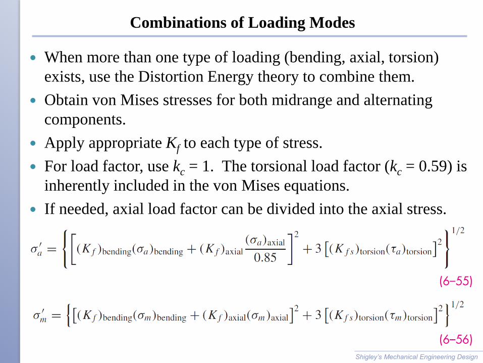
Combinations of Loading Modes
When more than one type of loading (bending, axial, torsion)
exists, use the Distortion Energy theory to combine them.
Obtain von Mises stresses for both midrange and alternating
components.
Apply appropriate Kf to each type of stress.
For load factor, use kc = 1. The torsional load factor (kc = 0.59) is
inherently included in the von Mises equations.
If needed, axial load factor can be divided into the axial stress.
Shigley’s Mechanical Engineering Design

Static Check for Combination Loading
Distortion Energy theory still applies for check of static yielding
Obtain von Mises stress for maximum stresses (sum of midrange
and alternating)
Stress concentration factors are not necessary to check for
yielding at first cycle
Alternate simple check is to obtain conservative estimate of s'max
by summing s'a and s'm
Shigley’s Mechanical Engineering Design
1/2
2 2
max
max
3a m a m
y
y
Sn
s s s
s
max a ms s s

Example 6–14
Shigley’s Mechanical Engineering Design

Example 6–14 (continued)
Shigley’s Mechanical Engineering Design

Example 6–14 (continued)
Shigley’s Mechanical Engineering Design

Example 6–14 (continued)
Shigley’s Mechanical Engineering Design

Example 6–14 (continued)
Shigley’s Mechanical Engineering Design
Fig. 6–32

Example 6–14 (continued)
Shigley’s Mechanical Engineering Design

Example 6–14 (continued)
Shigley’s Mechanical Engineering Design

Varying Fluctuating Stresses
Loading patterns may be
complex
Simplifications may be
necessary
Small fluctuations may be
negligible compared to large
cycles
Shigley’s Mechanical Engineering Design
Fig. 6–33

Cumulative Fatigue Damage
A common situation is to load at s1 for n1 cycles, then at s2 for n2
cycles, etc.
The cycles at each stress level contributes to the fatigue damage
Accumulation of damage is represented by the Palmgren-Miner
cycle-ratio summation rule, also known as Miner’s rule
where ni is the number of cycles at stress level si and Ni is the
number of cycles to failure at stress level si
c is experimentally found to be in the range 0.7 < c < 2.2, with an
average value near unity
Defining D as the accumulated damage,
Shigley’s Mechanical Engineering Design