Embed Size (px)
Citation preview
MacRoy® G PumpIOM ManualManual No : 53873Rev. : 02Rev. Date : 01/2017

3Installation, Operations & Maintenance Manual
PRECAUTIONSFor Pumps with PVC & 316SS Liquid EndsWHEN USED IN SWIMMING POOLS OR SPAS / HOT TUBS (ANSI / NSF 50)
Caution on Chemical Concentration:There is a potential for elevated chemical concentration during periods of no flow, for example, during backwash in the system. Steps, such as turning the pump off, should be taken during operation or installation to prevent this. Contact your sales representative or distributor about other external control options to help mitigate this risk.
Flow Indicating Device:To ensure operation of the pump it is recommended that some type of Flow Indicating Device be installed to measure water flow rates and be appropriate for the output of the pump. Contact your distributor or sales representative for further information.
Head Loss / Over Pressure Protection / Back Pressure-Anti-Siphon Valve:• Milton Roy metering pumps are positive displacement. Head loss is not applicable to the pump.• To ensure safe operation of the pump it is recommended that some type of safety / pressure relief valve be installed to protect the piping and other system components from failing due to excessive pressure.• If you are pumping downhill or into low or no system pressure, a back pressure / anti-siphon device should be installed to prevent over pumping or siphoning. Contact your distributor or sales representative for further information.
Additional Operation and Installation Instructions for 316SS or PVC Liquid Ends:• Application of this pump to swimming pool / spas only evaluated to NSF / ANSI 50.• There is a potential for elevated chemical concentration during periods of no flow, for example, during backwash in the system. Steps, such as turning the pump off, should be taken during operation or installation to prevent this. See your sales representative or distributor about other external control options to help mitigate this risk.• Liquid Compatibility CAUTION: Determine if the materials of construction included in the liquid handling portion of your pump are adequate for the solution (chemical) to be pumped. ALWAYS wear protective clothing, face shield, safety glasses and gloves when working on or near your metering pump. Additional precautions should be taken depending on the solution being pumped. Refer to MSDS precautions from your solution supplier. Reference a Milton Roy Material Selection Chart for aid in selecting appropriate material of construction for fluids of your specific metering pump. Contact your sales representative or distributor for further information.

4 Installation, Operations & Maintenance Manual
THIS PAGE INTENTIONALLY LEFT BLANK
5Installation, Operations & Maintenance Manual
SECTION 1 - DESCRIPTION . . . . . . . . . . . . . . . . . . . . . . . . . . . . . . . . . . . . . . . . . . . . . . . . . . . . . . . . . . . . . . . . . . . . . . . . . . . . . . . . . . . . . . . . . . . 71 .1 GENERAL INFORMATION . . . . . . . . . . . . . . . . . . . . . . . . . . . . . . . . . . . . . . . . . . . . . . . . . . . . . . . . . . . . . . . . . . . . . . . . . . . . . . . . . 71 .2 PRINCIPLE OF OPERATION . . . . . . . . . . . . . . . . . . . . . . . . . . . . . . . . . . . . . . . . . . . . . . . . . . . . . . . . . . . . . . . . . . . . . . . . . . . . . . . 71 .3 GENERAL SPECIFICATIONS . . . . . . . . . . . . . . . . . . . . . . . . . . . . . . . . . . . . . . . . . . . . . . . . . . . . . . . . . . . . . . . . . . . . . . . . . . . . . . . 81 .4 PRODUCT CODE . . . . . . . . . . . . . . . . . . . . . . . . . . . . . . . . . . . . . . . . . . . . . . . . . . . . . . . . . . . . . . . . . . . . . . . . . . . . . . . . . . . . . . . . 10
SECTION 2 - INSTALLATION . . . . . . . . . . . . . . . . . . . . . . . . . . . . . . . . . . . . . . . . . . . . . . . . . . . . . . . . . . . . . . . . . . . . . . . . . . . . . . . . . . . . . . . . . 112 .1 UNPACKING . . . . . . . . . . . . . . . . . . . . . . . . . . . . . . . . . . . . . . . . . . . . . . . . . . . . . . . . . . . . . . . . . . . . . . . . . . . . . . . . . . . . . . . . . . . . 112 .2 SAFETY PRECAUTIONS . . . . . . . . . . . . . . . . . . . . . . . . . . . . . . . . . . . . . . . . . . . . . . . . . . . . . . . . . . . . . . . . . . . . . . . . . . . . . . . . . . 112 .3 STORAGE 112 .4 MOUNTING . . . . . . . . . . . . . . . . . . . . . . . . . . . . . . . . . . . . . . . . . . . . . . . . . . . . . . . . . . . . . . . . . . . . . . . . . . . . . . . . . . . . . . . . . . . . 122 .5 PIPING . . . . . . . . . . . . . . . . . . . . . . . . . . . . . . . . . . . . . . . . . . . . . . . . . . . . . . . . . . . . . . . . . . . . . . . . . . . . . . . . . . . . . . . . . . . . . . 122 .6 LEAK DETECTION . . . . . . . . . . . . . . . . . . . . . . . . . . . . . . . . . . . . . . . . . . . . . . . . . . . . . . . . . . . . . . . . . . . . . . . . . . . . . . . . . . . . . . . 162 .7 ELECTRICAL CONNECTIONS . . . . . . . . . . . . . . . . . . . . . . . . . . . . . . . . . . . . . . . . . . . . . . . . . . . . . . . . . . . . . . . . . . . . . . . . . . . . . 16
SECTION 3 - OPERATION . . . . . . . . . . . . . . . . . . . . . . . . . . . . . . . . . . . . . . . . . . . . . . . . . . . . . . . . . . . . . . . . . . . . . . . . . . . . . . . . . . . . . . . . . . . . 173 .1 INITIAL START-UP . . . . . . . . . . . . . . . . . . . . . . . . . . . . . . . . . . . . . . . . . . . . . . . . . . . . . . . . . . . . . . . . . . . . . . . . . . . . . . . . . . . . . . . 17
SECTION 4 - MAINTENANCE . . . . . . . . . . . . . . . . . . . . . . . . . . . . . . . . . . . . . . . . . . . . . . . . . . . . . . . . . . . . . . . . . . . . . . . . . . . . . . . . . . . . . . . . . 194 .1 SPARE PARTS . . . . . . . . . . . . . . . . . . . . . . . . . . . . . . . . . . . . . . . . . . . . . . . . . . . . . . . . . . . . . . . . . . . . . . . . . . . . . . . . . . . . . . . . . . . 194 .2 SHIPPING PUMPS FOR REPAIR . . . . . . . . . . . . . . . . . . . . . . . . . . . . . . . . . . . . . . . . . . . . . . . . . . . . . . . . . . . . . . . . . . . . . . . . . . . 194 .3 PREVENTIVE MAINTENANCE . . . . . . . . . . . . . . . . . . . . . . . . . . . . . . . . . . . . . . . . . . . . . . . . . . . . . . . . . . . . . . . . . . . . . . . . . . . . 204 .4 CORRECTIVE MAINTENANCE . . . . . . . . . . . . . . . . . . . . . . . . . . . . . . . . . . . . . . . . . . . . . . . . . . . . . . . . . . . . . . . . . . . . . . . . . . . . 214 .4 .1 Check Valve Replacement . . . . . . . . . . . . . . . . . . . . . . . . . . . . . . . . . . . . . . . . . . . . . . . . . . . . . . . . . . . . . . . . . . . . . . . . . . . . . 214 .4 .1 .1 Plastic Check Valves (PVC, PVDF, POLY, & H2SO4) . . . . . . . . . . . . . . . . . . . . . . . . . . . . . . . . . . . . . . . . . . . . . . . . . . . . . . 214 .4 .1 .2 Models G6 & G7 Liquid End - Stainless Steel Check Valves (PVC, PVDF, POLY, & H2SO4) . . . . . . . . . . . . . . . . . . 224 .4 .1 .3 Model G5 Liquid End - Stainless Steel Check Valves (PVC, PVDF, POLY, & H2SO4) . . . . . . . . . . . . . . . . . . . . . . . . 234 .4 .1 .4 Model G5 Liquid End - Slurry Check Valves . . . . . . . . . . . . . . . . . . . . . . . . . . . . . . . . . . . . . . . . . . . . . . . . . . . . . . . . . . . 234 .4 .1 .5 Models G6 & G7 Liquid End - Slurry Check Valves . . . . . . . . . . . . . . . . . . . . . . . . . . . . . . . . . . . . . . . . . . . . . . . . . . . . . 244 .4 .1 .6 Models G5, G6 & G7 Liquid End - Polymer Check Valves . . . . . . . . . . . . . . . . . . . . . . . . . . . . . . . . . . . . . . . . . . . . . . . 244 .4 .2 Diaphragm Replacement . . . . . . . . . . . . . . . . . . . . . . . . . . . . . . . . . . . . . . . . . . . . . . . . . . . . . . . . . . . . . . . . . . . . . . . . . . . . . 254 .4 .2 .1 Diaphragm Removal (All types; Refer to Figures 6-12 ) . . . . . . . . . . . . . . . . . . . . . . . . . . . . . . . . . . . . . . . . . . . . . . . . 254 .4 .2 .2 Disassembly (Only Those Units With a “Hex Head“ Diaphragm Cap Design) . . . . . . . . . . . . . . . . . . . . . . . . . . . . 254 .4 .2 .3 Reassembly . . . . . . . . . . . . . . . . . . . . . . . . . . . . . . . . . . . . . . . . . . . . . . . . . . . . . . . . . . . . . . . . . . . . . . . . . . . . . . . . . . . . . . . . . 254 .4 .2 .4 Reinstallation of Assembly (Refer to Figures 6 Through 12) . . . . . . . . . . . . . . . . . . . . . . . . . . . . . . . . . . . . . . . . . . . . 254 .4 .3 Replacing Oil Seal . . . . . . . . . . . . . . . . . . . . . . . . . . . . . . . . . . . . . . . . . . . . . . . . . . . . . . . . . . . . . . . . . . . . . . . . . . . . . . . . . . . . . 26
SECTION 5 - TROUBLESHOOTING GUIDE . . . . . . . . . . . . . . . . . . . . . . . . . . . . . . . . . . . . . . . . . . . . . . . . . . . . . . . . . . . . . . . . . . . . . . . . . . . . . 28
TABLE OF CONTENTS
6 Installation, Operations & Maintenance Manual
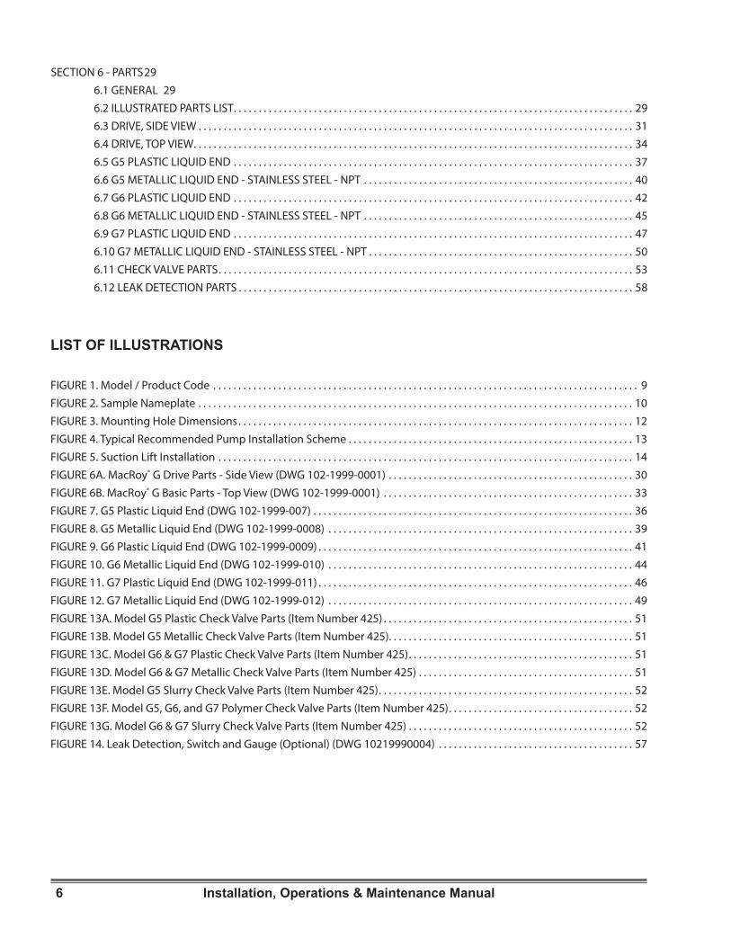
SECTION 6 - PARTS 296 .1 GENERAL 296 .2 ILLUSTRATED PARTS LIST . . . . . . . . . . . . . . . . . . . . . . . . . . . . . . . . . . . . . . . . . . . . . . . . . . . . . . . . . . . . . . . . . . . . . . . . . . . . . . . . 296 .3 DRIVE, SIDE VIEW . . . . . . . . . . . . . . . . . . . . . . . . . . . . . . . . . . . . . . . . . . . . . . . . . . . . . . . . . . . . . . . . . . . . . . . . . . . . . . . . . . . . . . . 316 .4 DRIVE, TOP VIEW . . . . . . . . . . . . . . . . . . . . . . . . . . . . . . . . . . . . . . . . . . . . . . . . . . . . . . . . . . . . . . . . . . . . . . . . . . . . . . . . . . . . . . . . 346 .5 G5 PLASTIC LIQUID END . . . . . . . . . . . . . . . . . . . . . . . . . . . . . . . . . . . . . . . . . . . . . . . . . . . . . . . . . . . . . . . . . . . . . . . . . . . . . . . . 376 .6 G5 METALLIC LIQUID END - STAINLESS STEEL - NPT . . . . . . . . . . . . . . . . . . . . . . . . . . . . . . . . . . . . . . . . . . . . . . . . . . . . . . 406 .7 G6 PLASTIC LIQUID END . . . . . . . . . . . . . . . . . . . . . . . . . . . . . . . . . . . . . . . . . . . . . . . . . . . . . . . . . . . . . . . . . . . . . . . . . . . . . . . . 426 .8 G6 METALLIC LIQUID END - STAINLESS STEEL - NPT . . . . . . . . . . . . . . . . . . . . . . . . . . . . . . . . . . . . . . . . . . . . . . . . . . . . . . 456 .9 G7 PLASTIC LIQUID END . . . . . . . . . . . . . . . . . . . . . . . . . . . . . . . . . . . . . . . . . . . . . . . . . . . . . . . . . . . . . . . . . . . . . . . . . . . . . . . . 476 .10 G7 METALLIC LIQUID END - STAINLESS STEEL - NPT . . . . . . . . . . . . . . . . . . . . . . . . . . . . . . . . . . . . . . . . . . . . . . . . . . . . . 506 .11 CHECK VALVE PARTS . . . . . . . . . . . . . . . . . . . . . . . . . . . . . . . . . . . . . . . . . . . . . . . . . . . . . . . . . . . . . . . . . . . . . . . . . . . . . . . . . . . 536 .12 LEAK DETECTION PARTS . . . . . . . . . . . . . . . . . . . . . . . . . . . . . . . . . . . . . . . . . . . . . . . . . . . . . . . . . . . . . . . . . . . . . . . . . . . . . . . 58
LIST OF ILLUSTRATIONS
FIGURE 1 . Model / Product Code . . . . . . . . . . . . . . . . . . . . . . . . . . . . . . . . . . . . . . . . . . . . . . . . . . . . . . . . . . . . . . . . . . . . . . . . . . . . . . . . . . . . . 9FIGURE 2 . Sample Nameplate . . . . . . . . . . . . . . . . . . . . . . . . . . . . . . . . . . . . . . . . . . . . . . . . . . . . . . . . . . . . . . . . . . . . . . . . . . . . . . . . . . . . . . . 10FIGURE 3 . Mounting Hole Dimensions . . . . . . . . . . . . . . . . . . . . . . . . . . . . . . . . . . . . . . . . . . . . . . . . . . . . . . . . . . . . . . . . . . . . . . . . . . . . . . . 12FIGURE 4 . Typical Recommended Pump Installation Scheme . . . . . . . . . . . . . . . . . . . . . . . . . . . . . . . . . . . . . . . . . . . . . . . . . . . . . . . . . 13FIGURE 5 . Suction Lift Installation . . . . . . . . . . . . . . . . . . . . . . . . . . . . . . . . . . . . . . . . . . . . . . . . . . . . . . . . . . . . . . . . . . . . . . . . . . . . . . . . . . . 14FIGURE 6A . MacRoy® G Drive Parts - Side View (DWG 102-1999-0001) . . . . . . . . . . . . . . . . . . . . . . . . . . . . . . . . . . . . . . . . . . . . . . . . . 30FIGURE 6B . MacRoy® G Basic Parts - Top View (DWG 102-1999-0001) . . . . . . . . . . . . . . . . . . . . . . . . . . . . . . . . . . . . . . . . . . . . . . . . . . 33FIGURE 7 . G5 Plastic Liquid End (DWG 102-1999-007) . . . . . . . . . . . . . . . . . . . . . . . . . . . . . . . . . . . . . . . . . . . . . . . . . . . . . . . . . . . . . . . . 36FIGURE 8 . G5 Metallic Liquid End (DWG 102-1999-0008) . . . . . . . . . . . . . . . . . . . . . . . . . . . . . . . . . . . . . . . . . . . . . . . . . . . . . . . . . . . . . 39FIGURE 9 . G6 Plastic Liquid End (DWG 102-1999-0009) . . . . . . . . . . . . . . . . . . . . . . . . . . . . . . . . . . . . . . . . . . . . . . . . . . . . . . . . . . . . . . . 41FIGURE 10 . G6 Metallic Liquid End (DWG 102-1999-010) . . . . . . . . . . . . . . . . . . . . . . . . . . . . . . . . . . . . . . . . . . . . . . . . . . . . . . . . . . . . . 44FIGURE 11 . G7 Plastic Liquid End (DWG 102-1999-011) . . . . . . . . . . . . . . . . . . . . . . . . . . . . . . . . . . . . . . . . . . . . . . . . . . . . . . . . . . . . . . . 46FIGURE 12 . G7 Metallic Liquid End (DWG 102-1999-012) . . . . . . . . . . . . . . . . . . . . . . . . . . . . . . . . . . . . . . . . . . . . . . . . . . . . . . . . . . . . . 49FIGURE 13A . Model G5 Plastic Check Valve Parts (Item Number 425) . . . . . . . . . . . . . . . . . . . . . . . . . . . . . . . . . . . . . . . . . . . . . . . . . . 51FIGURE 13B . Model G5 Metallic Check Valve Parts (Item Number 425) . . . . . . . . . . . . . . . . . . . . . . . . . . . . . . . . . . . . . . . . . . . . . . . . . 51FIGURE 13C . Model G6 & G7 Plastic Check Valve Parts (Item Number 425) . . . . . . . . . . . . . . . . . . . . . . . . . . . . . . . . . . . . . . . . . . . . . 51FIGURE 13D . Model G6 & G7 Metallic Check Valve Parts (Item Number 425) . . . . . . . . . . . . . . . . . . . . . . . . . . . . . . . . . . . . . . . . . . . 51FIGURE 13E . Model G5 Slurry Check Valve Parts (Item Number 425) . . . . . . . . . . . . . . . . . . . . . . . . . . . . . . . . . . . . . . . . . . . . . . . . . . . 52FIGURE 13F . Model G5, G6, and G7 Polymer Check Valve Parts (Item Number 425) . . . . . . . . . . . . . . . . . . . . . . . . . . . . . . . . . . . . . 52FIGURE 13G . Model G6 & G7 Slurry Check Valve Parts (Item Number 425) . . . . . . . . . . . . . . . . . . . . . . . . . . . . . . . . . . . . . . . . . . . . . 52FIGURE 14 . Leak Detection, Switch and Gauge (Optional) (DWG 10219990004) . . . . . . . . . . . . . . . . . . . . . . . . . . . . . . . . . . . . . . . 57
7Installation, Operations & Maintenance Manual
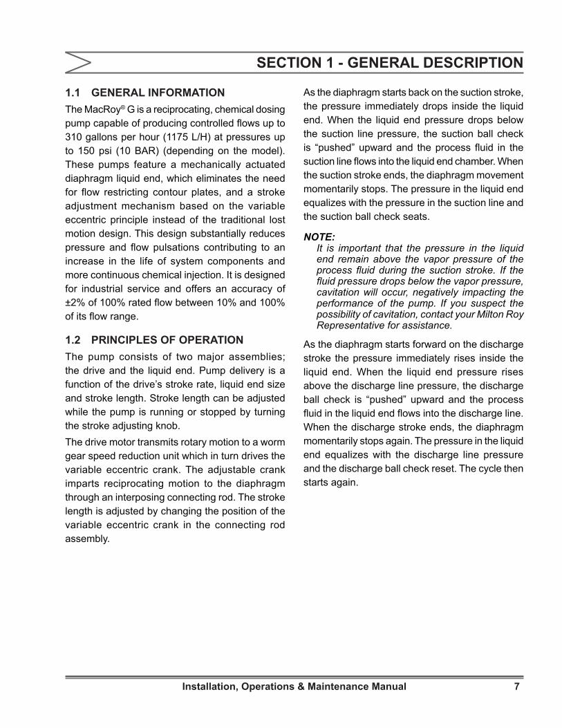
1.1 GENERAL INFORMATIONThe MacRoy® G is a reciprocating, chemical dosing pump capable of producing controlled flows up to 310 gallons per hour (1175 L/H) at pressures up to 150 psi (10 BAR) (depending on the model). These pumps feature a mechanically actuated diaphragm liquid end, which eliminates the need for flow restricting contour plates, and a stroke adjustment mechanism based on the variable eccentric principle instead of the traditional lost motion design. This design substantially reduces pressure and flow pulsations contributing to an increase in the life of system components and more continuous chemical injection. It is designed for industrial service and offers an accuracy of ±2% of 100% rated flow between 10% and 100% of its flow range.
1.2 PRINCIPLES OF OPERATIONThe pump consists of two major assemblies; the drive and the liquid end. Pump delivery is a function of the drive’s stroke rate, liquid end size and stroke length. Stroke length can be adjusted while the pump is running or stopped by turning the stroke adjusting knob. The drive motor transmits rotary motion to a worm gear speed reduction unit which in turn drives the variable eccentric crank. The adjustable crank imparts reciprocating motion to the diaphragm through an interposing connecting rod. The stroke length is adjusted by changing the position of the variable eccentric crank in the connecting rod assembly.
As the diaphragm starts back on the suction stroke, the pressure immediately drops inside the liquid end. When the liquid end pressure drops below the suction line pressure, the suction ball check is “pushed” upward and the process fluid in the suction line flows into the liquid end chamber. When the suction stroke ends, the diaphragm movement momentarily stops. The pressure in the liquid end equalizes with the pressure in the suction line and the suction ball check seats.
NOTE: It is important that the pressure in the liquid end remain above the vapor pressure of the process fluid during the suction stroke. If the fluid pressure drops below the vapor pressure, cavitation will occur, negatively impacting the performance of the pump. If you suspect the possibility of cavitation, contact your Milton Roy Representative for assistance.
As the diaphragm starts forward on the discharge stroke the pressure immediately rises inside the liquid end. When the liquid end pressure rises above the discharge line pressure, the discharge ball check is “pushed” upward and the process fluid in the liquid end flows into the discharge line. When the discharge stroke ends, the diaphragm momentarily stops again. The pressure in the liquid end equalizes with the discharge line pressure and the discharge ball check reset. The cycle then starts again.
SECTION 1 - GENERAL DESCRIPTION
8 Installation, Operations & Maintenance Manual
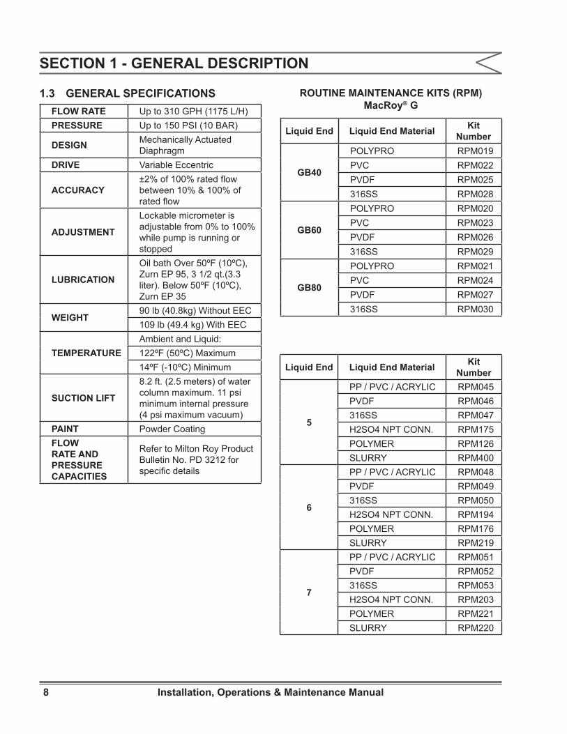
1.3 GENERAL SPECIFICATIONSFLOW RATE Up to 310 GPH (1175 L/H)PRESSURE Up to 150 PSI (10 BAR)
DESIGN Mechanically Actuated Diaphragm
DRIVE Variable Eccentric
ACCURACY±2% of 100% rated flow between 10% & 100% of rated flow
ADJUSTMENT
Lockable micrometer is adjustable from 0% to 100% while pump is running or stopped
LUBRICATION
Oil bath Over 50ºF (10ºC), Zurn EP 95, 3 1/2 qt.(3.3 liter). Below 50ºF (10ºC), Zurn EP 35
WEIGHT90 lb (40.8kg) Without EEC109 lb (49.4 kg) With EEC
TEMPERATUREAmbient and Liquid:122ºF (50ºC) Maximum14ºF (-10ºC) Minimum
SUCTION LIFT
8.2 ft. (2.5 meters) of water column maximum. 11 psi minimum internal pressure (4 psi maximum vacuum)
PAINT Powder CoatingFLOW RATE AND PRESSURE CAPACITIES
Refer to Milton Roy Product Bulletin No. PD 3212 for specific details
SECTION 1 - GENERAL DESCRIPTION
Liquid End Liquid End Material Kit Number
GB40
POLYPRO RPM019PVC RPM022PVDF RPM025316SS RPM028
GB60
POLYPRO RPM020PVC RPM023PVDF RPM026316SS RPM029
GB80
POLYPRO RPM021PVC RPM024PVDF RPM027316SS RPM030
ROUTINE MAINTENANCE KITS (RPM) MacRoy® G
Liquid End Liquid End Material Kit Number
5
PP / PVC / ACRYLIC RPM045PVDF RPM046316SS RPM047H2SO4 NPT CONN. RPM175POLYMER RPM126SLURRY RPM400
6
PP / PVC / ACRYLIC RPM048PVDF RPM049316SS RPM050H2SO4 NPT CONN. RPM194POLYMER RPM176SLURRY RPM219
7
PP / PVC / ACRYLIC RPM051PVDF RPM052316SS RPM053H2SO4 NPT CONN. RPM203POLYMER RPM221SLURRY RPM220
9Installation, Operations & Maintenance Manual
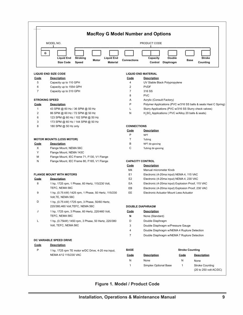
Figure 1. Model / Product Code
MacRoy G Model Number and Options
MODEL NO. PRODUCT CODE
G
Liquid End Size Code
Stroking Speed
MotorLiquid End
MaterialConnections
Capacity Control
Double Diaphragm
BaseStroke
Counting
LIQUID END SIZE CODE LIQUID END MATERIALCode Description Code Description
5 Capacity up to 110 GPH 4 UV Stable Black Polypropylene6 Capacity up to 1554 GPH 2 PVDF7 Capacity up to 310 GPH 7 316 SS
8 PVCSTROKING SPEED A Acrylic (Consult Factory)Code Description P Polymer Applications (PVC w/316 SS balls & seats Hast C Spring)
1 43 SPM @ 60 Hz / 36 SPM @ 50 Hz L Slurry Applications (PVC w/316 SS Slurry check valves)2 86 SPM @ 60 Hz / 72 SPM @ 50 Hz N H2SO4 Applications ( PVC w/Alloy 20 balls & seats)6 123 SPM @ 60 Hz / 102 SPM @ 50 Hz3 173 SPM @ 60 Hz / 144 SPM @ 50 Hz8 180 SPM @ 50 Hz only CONNECTIONS
Code DescriptionP NPT
MOTOR MOUNTS (LESS MOTOR) T TubingCode Description B NPT de-gassing
X Flange Mount, NEMA 56C C Tubing de-gassingY Flange Mount, NEMA 143CM Flange Mount, IEC Frame 71, F130, V1 FlangeN Flange Mount, IEC Frame 80, F165, V1 Flange CAPACITY CONTROL
Code DescriptionM4 Manual micrometer Knob
FLANGE MOUNT WITH MOTORS E1 Electronic (4-20ma input) NEMA 4, 115 VACCode Description E2 Electronic (4-20ma input) NEMA 4, 230 VAC
8 1 hp, 1725 rpm, 1 Phase, 60 Hertz, 115/230 Volt, TEFC, NEMA 56C
EA Electronic (4-20ma input) Explosion Proof, 115 VAC
EB Electronic (4-20ma input) Explosion Proof, 230 VAC9 1 hp, (0.75 kW) 1425 rpm, 1 Phase, 50 Hertz, 115/230
Volt,TE, NEMA 56CEE Electronic Actuator Mount Less Actuator
D 1 hp, (0.75 kW) 1725 rpm, 3 Phase, 50/60 Hertz, 220/380,460 Volt,TEFC, NEMA 56C DOUBLE DIAPHRAGM
J 1 hp, 1725 rpm, 3 Phase, 60 Hertz, 220/460 Volt, TEFC, NEMA 56C
Code DescriptionN None (Standard)
L 1 hp, (0.75kW) 1450 rpm, 3 Phase, 50 Hertz, 220/380 Volt, TEFC, NEMA 56C
D Double Diaphragm
3 Double Diaphragm w/Pressure Gauge
4 Double Diaphragm w/NEMA 4 Rupture Detection
7 Double Diaphragm w/NEMA 7 Rupture Detection
DC VARIABLE SPEED DRIVECode Description
P 1 hp, 1725 rpm TE motor w/DC Drive, 4-20 ma input, NEMA 4/12 115/230 VAC
BASE Stroke Counting
Code Description Code Description
N None N None
1 Simplex Optional Base 1 Stroke Counting (20 to 250 volt AC/DC)
MacRoy G Model Number and Options
MODEL NO. PRODUCT CODE
G
Liquid End Size Code
Stroking Speed
MotorLiquid End
MaterialConnections
Capacity Control
Double Diaphragm
BaseStroke
Counting

10 Installation, Operations & Maintenance Manual
SECTION 1 - GENERAL DESCRIPTION
1.4 PRODUCT CODEMacRoy® G pumps are available in a variety of different configurations. For a breakdown of the options included in a specific pump, compare the pump model number and product code found on the pump nameplate with the model / product code breakdown shown in Figure 1. A sample nameplate is shown in Figure 2.
IVYLAND, PA 18974 215-441-0800WWW.MILTONROY.COM
ASSEMBLED IN USA
Figure 2. Sample Nameplate
Liquid End
Codes
SPM @ GPH @ Max Pressure Max
PSI60Hz
50Hz
60Hz
50Hz
5
43 36 26 22
15086 72 53 44120 102 75 63173 144 106 88
- 180 - 110
6
43 36 36 30
10086 72 73 61120 102 104 87173 144 147 123
- 180 - 154
7
43 36 75 63
5086 72 149 124120 102 208 173173 144 300 250
- 180 - 312
Liquid End
Codes
SPM @ LPH @ Max Pressure Max
Bar60Hz
50Hz
60Hz
50Hz
5
43 36 98 82
1086 72 200 167120 102 284 237173 144 400 334
- 180 - 416
6
43 36 136 114
786 72 276 230
120 102 394 328173 144 556 464
- 180 - 583
7
43 36 284 237
3.586 72 564 470120 102 787 656173 144 1136 946
- 180 - 1181
English Units Metric Units
Flow Rate / Maximum Pressure Table & RPM Kits
11Installation, Operations & Maintenance Manual
SECTION 2 - INSTALLATION
2.1 UNPACKINGPumps are shipped Free On Board (FOB) factory or representative warehouse and the title passes to the customer when the carrier signs for receipt of the pump. In the event that damages occur during shipment, it is the responsibility of the customer to notify the carrier immediately and to file a damage claim. Carefully examine the shipping crate upon receipt from the carrier to be sure there is no obvious damage to the contents. Open the crate carefully so accessory items fastened to the inside of the crate will not be damaged or lost. Examine all material inside the crate and check against packing list to be sure that all items are accounted for and intact.
2.2 SAFETY PRECAUTIONS
WHEN INSTALLING, OPERATING, AND MAINTAINING THE MACROY®
G PUMP, KEEP SAFETY CONSIDERATIONS FOREMOST. USE PROPER TOOLS, PROTECTIVE CLOTHING, AND EYE PROTECTION WHEN WORKING ON THE EQUIPMENT AND INSTALL THE EQUIPMENT WITH A VIEW TOWARD ENSURING SAFE OPERATION. FOLLOW THE INSTRUCTIONS IN THIS MANUAL AND TAKE ADDITIONAL SAFETY MEASURES APPROPRIATE TO THE LIQUID BEING PUMPED. BE EXTREMELY CAREFUL IN THE PRESENCE OF HAZARDOUS SUBSTANCES (E.G, CORROSIVES, TOXINS, SOLVENTS, ACIDS, CAUSTICS, FLAMMABLES AND ETC.).
THE PERSONNEL RESPONSIBLE FOR INSTALLATION, OPERATION
AND MAINTENANCE OF THIS EQUIPMENT MUST BECOME FULLY ACQUAINTED WITH THE CONTENTS OF THIS MANUAL.
ANY SERVICING OF THIS EQUIPMENT MUST BE CARRIED
OUT WHEN THE UNIT IS STOPPED AND ALL PRESSURE HAS BEEN BLED FROM THE LIQUID END. SHUT-OFF VALVES IN SUCTION AND DISCHARGE SIDES OF THE LIQUID END SHOULD BE CLOSED WHILE THE UNIT IS BEING SERVICED. ACTIONS SHOULD BE TAKEN TO ELIMINATE THE POSSIBILITY OF ACCIDENTAL START-UP WHILE SERVICING IS TAKING PLACE. A NOTICE SHOULD BE POSTED BY THE POWER SWITCH TO WARN THAT SERVICING IS BEING CARRIED OUT ON THE EQUIPMENT. SWITCH OFF THE POWER SUPPLY AS SOON AS ANY FAULT IS DETECTED DURING OPERATION (EXAMPLES: ABNORMALLY HIGH DRIVE TEMPERATURE, UNUSUAL NOISE AND DIAPHRAGM FAILURE).
2.3 STORAGE
Short Term Storage (Less than 6 Months) It is preferable to store the material under a shelter in its original package to protect it from adverse weather conditions. In condensing atmospheres, follow the long term storage procedure.
Long Term Storage (Longer than 6 Months)The primary consideration in storage of pump equipment is to prevent corrosion of external and internal components. This corrosion is caused by natural circulation of air as temperature of the surroundings change from day to night, day to day, and from season to season. It is not practical to prevent this circulation which carries water vapor and other corrosive gasses, so it is necessary to protect internal and external surfaces from their effects to the extent possible. When the instructions given in this section are completed, the equipment is to be stored, sheltered and protected from direct exposure to weather.The prepared equipment should be covered with a plastic sheet or a tarpaulin, but in a manner which will allow air circulation and prevent capture of moisture. Equipment should be stored 12 inches or more above the ground. If equipment is to be shipped directly from Milton Roy into long term storage, contact Milton Roy to arrange for factory preparation.

12 Installation, Operations & Maintenance Manual
SECTION 2 - INSTALLATION
Pump Drive1. Flood the gearbox compartment with a high
grade lubricating oil / rust preventative such as Mobile Oil Corporation product “Mobilarma 524”. Fill the compartment completely to minimize air space and water vapor condensation. After storage, drain this material and refill the equipment with the recommended lubricant for equipment commissioning.
2. Remove drive motor and liquid end, and brush all unpainted metal surfaces with multipurpose grease (NLGI grade 2 or 3). Store these unattached.
Electrical Equipment1. Motors should be prepared in the manner
prescribed by their manufacturer. If information is not available, dismount and store motors as indicated in step 3 below.
2. Dismount electrical equipment (including motors) from the pump.
3. For all electrical equipment, place packets of Vapor Phase Corrosion Inhibitor (VPCI) inside of the enclosure, then place the entire enclosure, with additional packets, inside a plastic bag. Seal the bag tightly closed. Contact Milton Roy Service Department for recommended VPCI materials.
2.4 MOUNTINGTO AVOID POSSIBLE DAMAGE TO EITHER PUMP OR PERSONNEL,
BOLT PUMP DOWN AS SOON AS IT IS IN POSITION.
Support the pump firmly in a level position on a solid, vibration-free foundation, preferably with the base above floor level to protect the pump from wash downs and to provide easier access for service. Be sure to allow enough space around the pump for easy access during maintenance operations, pump adjustments, and / or oil filling or draining procedures.
MacRoy® G pumps are provided with mounting holes to accommodate anchor bolts. Refer to Figure 3 for mounting hole dimensions. Some MacRoy® G pumps are shipped with motors dismounted. After anchoring pump in position, install motor, referring to Figure 6, Sheet 1. Make sure spring (360) provided with pump is installed in worm shaft prior to motor installation. Pumps installed outdoors should be protected by a shelter.
2.5 PIPING
NPSH ConsiderationsSize piping to accommodate peak instantaneous flow. Because of the reciprocating motion of the pump diaphragm, pump delivery follows an approximate sine curve with a peak instantaneous flow pi (3.14) times the average flow. Therefore, piping must be designed for a flow 3.14 times the pump capacity; this means that a pump rated for 88 gallons per hour (333.1 L/hr.) requires piping sufficient for 3.14 x 88 gph, or 276 gph (1044.7 L/hr.).
Figure 3. Mounting Hole Dimensions
9”
4½”CL
CL
(228.6 mm)
(114.3 mm)
Motor
Liquid End
0.354” (9 mm) Dia.Mounting Holes

13Installation, Operations & Maintenance Manual
SECTION 2 - INSTALLATION
To minimize viscous flow losses when handling viscous liquids, it may be necessary to use suction piping up to four times larger than the size of the suction connection on the pump. If in doubt, contact your nearest Milton Roy representative to determine the necessary pipe size.
General Piping Considerations• Use extreme care in piping to plastic liquid end
pumps with rigid pipe such as PVC. If excessive stresses or vibration is unavoidable, flexible connections are recommended.
• Use piping materials that will resist corrosion by the liquid being pumped. Use care in selecting materials to avoid galvanic corrosion at pump liquid end connections.
• Use piping heavy enough to withstand maximum pressures.
• Remove burrs, sharp edges and debris from inside piping. Blow out all pipe lines before making final connections to pump.
• Because vapor in the liquid end will cause inaccurate pump delivery, piping should be sloped to prevent vapor pockets
• W h e n p u m p i n g s u s p e n d e d s o l i d s (such as slurries), install plugged crosses at all 90° line turns to permit line cleaning without dismantling piping.
• See Figure 4 for a typical recommended pump installation scheme.
Figure 4. Typical Recommended Pump Installation Scheme
14 Installation, Operations & Maintenance Manual
SECTION 2 - INSTALLATION
Suction Piping Considerations• It is preferable to have the suction of the pump
flooded by locating the liquid end below the lowest level of the liquid in the supply tank. Installing the supply vessel on the suction line close to the pump can help ensure a flooded suction line. (Consult Milton Roy for assistance in such applications.)
• Avoid negative suction pressure conditions (suction lift), as such conditions adversely affect metering accuracy. A lift of 8.2 feet (2.5 meters) of water column is the maximum suction lift permissible.
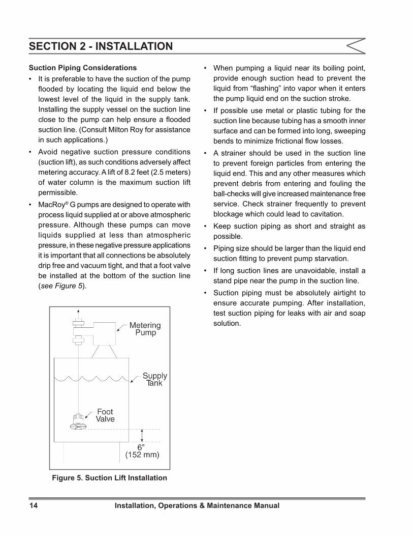
• MacRoy® G pumps are designed to operate with process liquid supplied at or above atmospheric pressure. Although these pumps can move liquids supplied at less than atmospheric pressure, in these negative pressure applications it is important that all connections be absolutely drip free and vacuum tight, and that a foot valve be installed at the bottom of the suction line (see Figure 5).
• When pumping a liquid near its boiling point, provide enough suction head to prevent the liquid from “flashing” into vapor when it enters the pump liquid end on the suction stroke.
• If possible use metal or plastic tubing for the suction line because tubing has a smooth inner surface and can be formed into long, sweeping bends to minimize frictional flow losses.
• A strainer should be used in the suction line to prevent foreign particles from entering the liquid end. This and any other measures which prevent debris from entering and fouling the ball-checks will give increased maintenance free service. Check strainer frequently to prevent blockage which could lead to cavitation.
• Keep suction piping as short and straight as possible.
• Piping size should be larger than the liquid end suction fitting to prevent pump starvation.
• If long suction lines are unavoidable, install a stand pipe near the pump in the suction line.
• Suction piping must be absolutely airtight to ensure accurate pumping. After installation, test suction piping for leaks with air and soap solution.
Figure 5. Suction Lift Installation
15Installation, Operations & Maintenance Manual
SECTION 2 - INSTALLATION
Discharge Piping Considerations• Install pipe large enough to prevent excessive
pressure losses on the discharge stroke of the pump. Maximum pressure at the discharge fitting on the liquid end must be kept at or below the rated pressure (Max. allowable working pressure shown on the pump nameplate).
• The pump will not deliver a controlled flow unless the discharge line pressure is 10 psi greater than the suction line pressure. There are a number of ways to create an artificial pressure, such as by installing a back pressure valve. (Please contact Milton Roy for recommendations to increase back pressure in slurry applications.)
• When pumping water-treatment chemicals directly into boiler drums, use one liquid end assembly for each boiler drum. Discharging into a manifold having the slightest pressure difference between its several discharge connections can diminish metering accuracy as the outlet with the lowest pressure will receive more liquid than the other outlets.
Back Pressure ValvesA Milton Roy Back Pressure Valve should be installed in the discharge line near the pump to ensure sufficient discharge head pressure for proper pump metering action. Normally, the valve should be located near the pump; however, back pressure valves for large pumps with long and extremely small discharge lines may have to be installed near the point of discharge into the process (to minimize siphoning tendencies).
Pulsation DampenersAn accumulator, surge chamber, surge suppressor, or pulsation dampener should be used with the back pressure valve in the discharge line to absorb the flow peaks between the pump and the back pressure valve. Without the pulsation dampener the valve mechanism will snap open and closed with the surge from each pump stroke. The pulsation dampener will allow the back pressure valve to oscillate about a partly-closed position, thus minimizing wear on the valve. Discharge line pulsation dampeners offer the further advantage of limiting the flow and pressure variations characteristic of this kind of pump. Installing a properly sized pulsation dampener will improve pump performance and may reduce system costs dramatically by permitting the substitution of smaller piping. Please contact Milton Roy for further information on pulsation dampeners.
Safety ValvesMotor-driven positive displacement pumps can develop excessive discharge pressures long before thermal overload devices interrupt the motor electrical circuit. To prevent a blocked discharge line from causing damage to the pump, piping, or process equipment, install a Milton Roy Safety Valve in the pump discharge line. This valve is designed and sized to handle system flow rates and pressures safely while resisting corrosion by the process liquid. Install the safety valve in the discharge line between the pump and the nearest shut-off valve. (This will prevent pump damage from accidental valve closure.) Pipe the safety valve outlet back to the suction tank or to drain, but in either case ensure that the pipe end is continuously visible so safety valve leakage may be detected. Milton Roy safety valves must be installed at top of supply tank in order to function properly (see Figure 4).

16 Installation, Operations & Maintenance Manual
SECTION 2 - INSTALLATION
Check ValvesA check valve should be installed at the point where the discharge line enters a boiler or other high-pressure vessel. This will prevent back flow through the discharge piping and will isolate the pump discharge from system pressures (a safety consideration).
Shut-off ValvesProvide shut-OFF valves in both suction and discharge lines next to the pump. Locate discharge line shut-OFF valve downstream from the inlet connection of the safety valve. Figure 4 shows recommended valve locations.
2.6 LEAK DETECTION
Without double diaphragm option:MacRoy® G pumps are equipped with a leak detection port. For ease of installation, each pump has a plastic tubing connector installed in the leak detection port (See item 448 in Figure 6, Sheet 2). In the event of a failure of the oil seal (70 in Figure 6, Sheet 1) or PTFE diaphragm assembly (260 in Figures 7 through 12), pump drive oil or process fluid will escape from this leakage port. During pump installation, actions should be taken to insure that this leakage is safely collected by installing tubing between the leak detection port and an appropriate containment vessel.
With double diaphragm option:The MacRoy® also is available with a double diaphragm option that includes tubing to a pressure gauge and switch as shown in Figure 14. In the event of a diaphragm leak the process fluid is trapped inside the system and the pressure switch (760, Figure 14) is tripped to set an alarm or shutdown.This leak detection system is not filled with any fluid and will only be pressurized in the event of a seal failure. A drain (790, Figure 14) is provided for pressure relief prior to system disassembly.
2.7 ELECTRICAL CONNECTIONSEnsure that the electrical supply matches the pump motor nameplate characteristics.
OPERATION WITH THE WRONG MOTOR ROTATION WILL DAMAGE
THE PUMP AND MOTOR AND VOID THE WARRANTY.
Before operating the pump, check the direction of rotation of the motor to be sure it matches the direction of the arrow stamped on the motor (rotation should be clockwise when viewed from the top of the motor). If motor rotation is incorrect, refer to the motor data plate or motor manufacturer’s instructions for reversing.
DO NOT FORGET TO CONNECT THE PUMP TO AN EARTH
GROUND.
Electric protection of the motor (fuses, overload meters or relays) should correspond to the rated current indicated on the motor data plate.
17Installation, Operations & Maintenance Manual
SECTION 3 - OPERATION
3.1 INITIAL START-UPFAILURE TO CHECK TORQUE ON NONMETALLIC HEAD
BOLTS PRIOR TO STARTUP AND AFTER ONE WEEK OF OPERATION MAY EXPOSE OPERATING PERSONNEL TO HAZARDOUS LIQUIDS.
Check the torque on all non-metallic head bolts prior to startup. Recheck torque on all non-metallic head bolts after pump has been operating for one week. Torque the head assembly screws in a crosswise pattern as follows:1. Liquid End Size G5 and G6 non-metallic head
bolts to 90 inch pounds.2. Liquid End Size G7 non-metallic head bolts to
125 inch pounds.Check that all mounting bolts are tight, piping is installed properly, and the discharge line is open. Check oil drain plug for tightness. Remove the oil fill cap and fill the pump casing until level is between the markings on the oil fill cap dipstick, (approximately 3 quarts (2.8 Liters)).
NOTE: The oil furnished with the pump is grade AGMA No. 5 EP with a viscosity of 1000 SSU at 100°F (218.4 cSt at 40°C). For operation in ambient temperatures below 50°F (10°C), substitute AGMA No. 2 EP with a viscosity of 400 SSU at 100°F (86.4 cSt at 40°C). Manufacturers’ equivalent oils are shown below.
ABOVE 50°FChevron N.L. Gear Compound 220Exxon Spartan E.P. 220Mobil Mobilgear 630Texaco Meropa 220Shell Omaha 220
BELOW 50°FChevron N.L. Gear Compound 68Exxon Spartan E.P. 68Mobil Mobilgear 626Texaco Meropa 68Shell Omaha 68
BEFORE SWITCHING ON POWER TO THE PUMP, TURN
THE CAPACITY ADJUSTMENT KNOB TO ZERO. CHECK THAT ALL SHUT-OFF VALVES IN THE SUCTION AND DISCHARGE LINES ARE OPEN BEFORE INCREASING THE CAPACITY ADJUSTMENT FROM ZERO.
Manual Capacity ControlTo adjust pump capacity, loosen the stroke locking knob (320, Figure 6, Sheet 2) located in the pump side cover. Pump capacity is adjusted by turning the micrometer type stroke adjustment knob (330) clockwise to decrease capacity or counterclockwise to increase capacity as required. The adjustment scale is marked in percent (%) of full stroke, with calibration lines on the knob at 1% intervals. After adjusting the knob to the desired capacity setting, hand tighten the stroke locking screw to maintain the capacity setting.
Filling Pumping SystemIt is especially important that pump suction and discharge lines be free of entrained air. To ensure this condition, operate the pump without any discharge pressure and fill the entire pumping system with liquid before starting pressure tests. A simple method to assure priming of the pump is to install a tee and a shut-off valve at the discharge connection of the pump.If the pump is idle for long periods, temperature changes in the process liquid may produce air in the system. To discharge the air, install a valve in the discharge line which will allow the process liquid to be pumped to exhaust when starting thepump.
18 Installation, Operations & Maintenance Manual
Capacity CalibrationAfter the first 12 hours of operation, the pump may be tested and calibrated to find the exact pump capacity under specific operating conditions.Usually, calibrating the pump at only 100, 50 and 10 percent capacity settings is enough to indicate pump performance throughout the adjustment range.The pump can be calibrated by measuring the decrease in liquid level pumped from a calibrated vessel. This method is recommended for hazardous liquids because it eliminates operator contact with the liquid. Milton Roy test-tube Calibration Columns are available for convenient and accurate calibration of any pump.
SECTION 3 - OPERATION
19Installation, Operations & Maintenance Manual
SECTION 4 - MAINTENANCE
4.1 SPARE PARTSTo avoid excessive downtime in the event of a parts malfunction, the spare parts shown below should be stocked for each pump to prevent serious delays in repairs. Refer to Figures 7-13 and the accompanying parts lists. For your convenience, these parts can be purchased either separately or packaged in the form of Routine Preventive Maintenance (RPM) Kits. RPM kit numbers are listed in Section 1. RPM kit numbers RPM019 through RPM030 contain pre-assembled diaphragms, oil seal and check valve parts. Cap piece (240), set screw (250), diaphragm (260), and support nut (270) is pre-assembled in kits RPM019 through RPM030. A spanner wrench, which may not always be available in the field, is required to disassemble the diaphragm assembly. RPM Kits RPM045 through RPM053, and RPM126 through RPM220 contain a diaphragm, oil seal, and check valve parts. MacRoy® G pumps built with the latest design do not need a spanner wrench to disassemble the diaphragm assembly. The diaphragm assembly can be disassembled with a 30mm socket (Section 4, paragraph 4.4.2). The diaphragm can then be replaced. Either type of kit can be used for your pump. The user must decide which type is better for them. When ordering RPM Kits RPM045 through RPM053 for an old style pump, where a spanner wrench is required to disassemble the diaphragm assembly, order a new hex head support nut (270) with the RPM kit. Future maintenance on the MacRoy® pump will not require a spanner wrench.
G5, Metallic Liquid End1. Diaphragm (260)2. Oil Seal (70)3. Check Valve Assemblies (425)(See parts list)
All Other Liquid Ends1. Diaphragm (260)2. Oil Seal (70)3. Seat, O-Ring, Ball Set (423)(See parts list)Parts orders must include the following:1. Quantity required2. Part number3. Part description4. Pump serial number (found on nameplate)5. Pump model number (found on nameplate)6. Pump product code (found on nameplate)Always include the serial number, model number, and product code in all correspondence regarding the unit.
Drive Worms and GearsWorms (Fig 6, Item 342) and gears (50) must be sold in sets to assure proper operation.
4.2 SHIPPING PUMPS FOR REPAIRPumps will not be accepted for repair without a Return Material Authorization Form, available from the Aftermarket Department or at the website (www.miltonroy.com). Process liquid must be flushed from the pump liquid end, and oil should be drained from the pump housing before the pump is shipped. Label the unit clearly to indicate the liquid being pumped.
NOTE: Federal law prohibits handling of equipment that is not accompanied by an OSHA Safety Data Sheet (SDS). A completed SDS must be packed in the shipping crate with any pump returned to the factory. These safety precautions will aid the troubleshooting and repair procedure and preclude serious injury to repair personnel from hazardous residue in the pump liquid end.
All inquiries or parts orders should be addressed to your local Mil ton Roy representat ive. Representatives can be found on our website (www.miltonroy.com).

20 Installation, Operations & Maintenance Manual
4.3 PREVENTIVE MAINTENANCEMilton Roy pumps are carefully designed, manufactured, assembled, and quality tested to give reliable service with minimal maintenance. However, a weekly maintenance check is recommended to visually confirm proper operation of the pump.
DriveInitially, change gear drive oil after the first 250 hours of operation. Then change drive oil after every 4000 hours of operation or every six months, whichever comes first. Refer to “Initial Start-up” in Section 3, Operation, for information on recommended oil and oil capacity.
NOTE: When adding oil, pour in a thin, slow stream to avoid overflow.
Diaphragm AssemblyThe MacRoy® G diaphragm assembly should be replaced every 4000 hours of operation to avoid the possibility of failure. Refer to the instructions in the “Corrective Maintenance” section.
Oil SealThe MacRoy® G oil seal should be replaced every 4000 hours of operation to avoid the possibility of failure. Oil seal replacement requires the removal of the diaphragm assembly, so it is recommended that the oil seal and diaphragm be replaced at the same time. Refer to the instructions in the “Corrective Maintenance” section.
Check ValvesMilton Roy recommends that check valve balls, seats, gaskets, and O-rings be replaced on an annual basis. If highly corrosive material (acids, slurries, etc.) is being pumped, some applications may require more frequent replacement. To determine if check valves need maintenance, disassemble the check valves following the instructions in the “Corrective Maintenance” section.Inspect the ball check and seat for chemical or physical damage. The ball should be perfectly round and free of pits, mars, or scratches. The seat should retain a sharp edge where the ball contacts for proper sealing. If the seat edge is worn or damaged, or has any pits, mars, or scratches, it should be replaced. If the ball and / or seat is excessively damaged, the replacement schedule should be shortened accordingly. If the ball and seat are both in good condition, the replacement schedule can be lengthened.Complete instructions for replacing worn check valve parts are given in the “Corrective Maintenance” section.
SECTION 4 - MAINTENANCE
21Installation, Operations & Maintenance Manual
4.4 CORRECTIVE MAINTENANCEBEFORE CARRYING OUT ANY SERVICING OPERATION ON
THE METERING UNIT OR PIPES, DISCONNECT ELECTRICAL POWER FROM THE PUMP, AND TAKE THE NECESSARY STEPS TO ENSURE THAT THE HARMFUL LIQUID THEY CONTAIN CANNOT ESCAPE OR COME INTO CONTACT WITH PERSONNEL. SUITABLE PROTECTIVE EQUIPMENT MUST BE PROVIDED. CHECK THAT ALL PRESSURE HAS BEEN BLED FROM THE PUMP DRIVE AND PUMP LIQUID END BEFORE PROCEEDING WITH DISMANTLING.
Cleaning Fouled Check ValvesCheck valve assemblies are designed to be self cleaning and should seldom need servicing. Fouled check valves can usually be cleaned by pumping a solution of mild detergent and warm water (if compatible with liquid being pumped) for 15 minutes, followed by flushing with water.
4.4.1 Check Valve Replacement
GeneralBefore beginning work on the valve assemblies, make sure the shut-off valves are closed and that pressure has been bled from the system. When replacing the valves, take care to systematically change their O-rings and / or gaskets. Take care to properly assemble the valve assemblies; the ball must be placed on the sharp edge of the seats.Check valves are supplied in four different configurations: plastic, stainless steel, slurry, and polymer. Be sure to refer to the appropriate instructional set below.
BE SURE TO FOLLOW INSTRUCTIONS CAREFULLY
AND REFER TO THE APPROPRIATE FIGURE WHEN REASSEMBLING CHECK VALVES. IF CHECK VALVE CARTRIDGES ARE INSTALLED INCORRECTLY, ONE OF THE FOLLOWING WILL OCCUR: (A) IMMEDIATE SEVERE DAMAGE TO PUMP MECHANISM, (B) NO PUMPING, (C) REVERSE PUMPING ACTION (FROM DISCHARGE LINE INTO SUCTION LINE).
4.4.1.1 Plastic Check Valves (PVC, PVDF, Poly, H2SO4, Figure 13A or 13C):
DisassemblyCheck pump data plate for model number.1. Unscrew the union nut (435). The union end
(445) is held in place by the union nut and will separate easily from the other liquid end parts.
2. Unscrew the ball guide (424) from the liquid end.
3. Screw the union nut part way (one or two turns) onto the end of the ball guide that has the seat in it. Be sure the union nut is on loosely. This will allow a gap for the seat (420) to fall into as it is removed from the ball guide.
4. Set the ball guide / union nut onto a flat surface with the union nut down. Looking into the top of the ball guide, you will see four large holes surrounding one small hole. Insert a thin, blunt instrument such as a hex head screwdriver into the small center hole until it rests on the top of the ball (422).
IF YOU ARE DISASSEMBLING UNIT OR INSPECTION ONLY, BE
SURE TO USE A BLUNT INSTRUMENT AND TAP GENTLY TO AVOID DAMAGING THE BALL. IF THE BALL AND / OR SEAT ARE DAMAGED DURING DISASSEMBLY, THEY WILL HAVE TO BE REPLACED. IF AVAILABLE, TO AVOID DAMAGE, IT IS ADVISABLE TO USE GENTLE AIR PRESSURE (APPLIED AT END OPPOSITE THE SEAT - 420) FOR BALL AND SEAT REMOVAL.
5. Tap screwdriver gently with a hammer until the ball and seat are released from the ball guide.
6. Carefully remove the two or three O-rings (depending on model number) from the ball guide and seat.
7. Carefully clean any parts to be reused. If any chemicals are used in the cleaning process, ensure that they are compatible with the process liquid.
SECTION 4 - MAINTENANCE
22 Installation, Operations & Maintenance Manual
Reassembly1. Fit new O-rings into position on the ball guide
and seat.
NOTE: To assure a tight, leak free seal, new O-rings should be used each time the check valves are disassembled.
2. Drop the ball into the curved inner chamber end of the ball guide.
IF THE SEAT IS IMPROPERLY POSITIONED, THE BALL WILL
NOT CREATE A TIGHT SEAL AND POOR PUMPING PERFORMANCE WILL RESULT.
3. Set the ball guide on a flat surface so that the side with the ball faces upwards. Position seat on the ball guide, trapping the ball inside. When the seat is pressed into the ball guide, the bevelled edge of the seat must be facing outward. The bevel should not face the inside of the check valve (refer to Figure 13A or 13C). Use a flat surface such as a board to press the seat into the ball guide with firm, even pressure.
THE ORDER OF ASSEMBLY AND ORIENTATION OF THE
SUCTION AND DISCHARGE CHECK VALVES IS DIFFERENT. REFER TO FIGURES 7, 9, 11, 13A, AND 13C FOR PROPER ASSEMBLY ORDER AND ORIENTATION. IF CHECK VALVE CARTRIDGES ARE INSTALLED INCORRECTLY, ONE OF THE FOLLOWING WILL OCCUR: (A) IMMEDIATE SEVERE DAMAGE TO PUMP MECHANISM, (B) NO PUMPING, (C) REVERSE PUMPING ACTION (FROM DISCHARGE LINE INTO SUCTION LINE).
4. Position the union end (445) onto the correct end of the ball guide. Refer to Figure 13A or 13C, as the correct end is determined by whether the valve is intended for the suction or discharge port of the liquid end. Slip the union nut (435) over the union end and screw tightly (hand tight only) onto the ball guide.
5. Screw the valve assembly into the liquid end body (hand tight only), Do not over tighten.
4.4.1.2 Models G6 & G7 Liquid Ends - Stainless Steel Check Valves (PVC, PVDF, Poly, H2SO4, Figure 13D):
Disassembly1. Unscrew the three screws (441 & 442) and
remove them and their three washers (439).2. Remove the valve clamp (437).3. The connection (435), seat (420), ball (422)
and ball guide (424) should all now slip apart easily.
4. Remove and discard the three gaskets (419).5. Carefully clean any parts to be reused. If any
chemicals are used in the cleaning process, ensure that they are compatible with the process liquid.
Reassembly1. Drop the ball into the curved inner chamber end
of the ball guide.DO NOT REUSE OLD GASKETS (419). EVEN IF BALL AND SEAT
ARE NOT WORN AND DO NOT NEED REPLACING, NEW GASKETS MUST BE USED ANY TIME THE CHECK VALVES ARE DISASSEMBLED.
2. Place a new gasket on the rim of the ball guide (424), and sit the seat on top of the ball guide, trapping the ball and gasket between the seat and ball guide.
THE ORDER OF ASSEMBLY AND ORIENTATION OF THE
SUCTION AND DISCHARGE CHECK VALVES IS DIFFERENT. REFER TO FIGURES 10, 12, AND 13D FOR PROPER ASSEMBLY ORDER AND ORIENTATION. IF CHECK VALVE CARTRIDGES ARE INSTALLED INCORRECTLY, ONE OF THE FOLLOWING WILL OCCUR: (A) IMMEDIATE SEVERE DAMAGE TO PUMP MECHANISM, (B) NO PUMPING, (C) REVERSE PUMPING ACTION (FROM DISCHARGE LINE INTO SUCTION LINE).
SECTION 4 - MAINTENANCE
23Installation, Operations & Maintenance Manual
3. Position the connection (435) onto the correct end of the ball guide with a gasket trapped between the two metal surfaces. Refer to Figure 13D, as the correct end is determined by whether the valve is intended for the suction or discharge port of the liquid end.
4. Position the check valve assembly onto the liquid end, trapping a gasket between the two metal surfaces (Seat and pump head).
5. Slide the valve clamp (437) over the connection (435) and screw into the liquid end using the three screws (441,442) and their split washers (439). Since one screw (441) is shorter than the others, be sure that it is screwed into the appropriate hole.
4.4.1.3 Model G5 Liquid End - Stainless Steel Check Valve (PVC, PVDF, POLY, H2SO4, Figure 13B):
DisassemblyG5 & G6 stainless steel check valves differ from the plastic versions in that the ball seat is integral to the ball guide. The seats cannot easily be inspected for damage or wear. If you suspect that the check valve may be damaged or worn, replace the entire check valve assembly as per the instructions below.1. Unscrew the coupling (445).2. Unscrew the ball guide (424) from the liquid
end.3. Remove and discard the O-rings (419).4. Carefully clean any parts to be reused. If any
chemicals are used in the cleaning process, ensure that they are compatible with the process liquid.
ReassemblyTHE ORDER OF ASSEMBLY AND ORIENTATION OF THE
SUCTION AND DISCHARGE CHECK VALVES IS DIFFERENT. REFER TO FIGURES 8 AND 13B FOR PROPER ASSEMBLY ORDER AND ORIENTATION. IF CHECK VALVE CARTRIDGES ARE INSTALLED INCORRECTLY, ONE OF THE FOLLOWING WILL OCCUR: (A) IMMEDIATE SEVERE DAMAGE TO PUMP MECHANISM, (B) NO PUMPING, (C) REVERSE PUMPING ACTION (FROM DISCHARGE LINE INTO SUCTION LINE).
1. Screw the correct end of the check valve assembly into the l iquid end (Refer to Figure 13B), trapping a new O-ring between the liquid end and the check valve assembly.
NOTE: To assure a tight, leak free seal, new O-rings should be used each time the check valves are disassembled.
2. Screw the coupling (445) onto the check valve assembly, trapping a new O-ring (419, 423) between the coupling and the check valve assembly.
4.4.1.4 Model G5 Liquid End - Slurry Check Valves:Replacement
THE ORDER OF ASSEMBLY AND ORIENTATION OF THE
SUCTION AND DISCHARGE CHECK VALVES IS DIFFERENT. REFER TO FIGURES 7 AND 13E FOR PROPER ASSEMBLY ORDER AND ORIENTATION. IF CHECK VALVE CARTRIDGES ARE INSTALLED INCORRECTLY, ONE OF THE FOLLOWING WILL OCCUR: (A) IMMEDIATE SEVERE DAMAGE TO PUMP MECHANISM, (B) NO PUMPING, (C) REVERSE PUMPING ACTION (FROM DISCHARGE LINE INTO SUCTION LINE).
1. Unscrew the coupling (445).2. Unscrew the valve body (424) from the pump
head (280).3. Remove and discard the valve assembly:
assembly includes two O-rings (419), slurry seal ring (420), ball (422), check valve body (424) and dowel pin.
4. Clean the new valve assembly and threaded port in the head (280).
SECTION 4 - MAINTENANCE
24 Installation, Operations & Maintenance Manual
NOTE: To assure a tight, leak free seal, new O-rings should be used each time the check valves are disassembled.
5. Screw the correct end of the check valve assembly into the l iquid end (Refer to Figure 13E), trapping a new O-ring (419) between the liquid end and the check valve assembly.
6. Screw the coupling (445) onto the check valve assembly, trapping a new O-ring (419) between the coupling and the check valve assembly.
4.4.1.5 Models G6 & G7 Liquid End - Slurry Check Valves (Figure 13G):
ReplacementTHE ORDER OF ASSEMBLY AND ORIENTATION OF THE
SUCTION AND DISCHARGE CHECK VALVES IS DIFFERENT. REFER TO FIGURE 13G FOR PROPER ASSEMBLY ORDER AND ORIENTATION. IF CHECK VALVE CARTRIDGES ARE INSTALLED INCORRECTLY, ONE OF THE FOLLOWING WILL OCCUR: (A) IMMEDIATE SEVERE DAMAGE TO PUMP MECHANISM, (B) NO PUMPING, (C) REVERSE PUMPING ACTION (FROM DISCHARGE LINE INTO SUCTION LINE).
1. Unscrew the valve body (424) from the pump head (280).
2. Remove the valve assembly: assembly includes ball (421), seat (420), valve body (424), and three O-rings (419).
3. Remove and discard the O-rings (419), seat (420) and ball (421).
4. Clean the valve body (424) and threaded port in the head (280).
5. Place a new O-ring (419) around seat (420). Place new seat (420) and new ball (422) inside valve body (424).
6. Add O-ring (419) and install new check valve assembly in orientation shown.
NOTE: To assure a tight, leak free seal, new O-rings should be used each time the check valves are disassembled.
7. Screw the correct end of the check valve assembly into the l iquid end (Refer to Figure 13G), trapping a new O-ring (419) between the liquid end and the check valve assembly.
8. Screw the coupling (445) onto the check valve assembly, trapping a new O-ring (419) between the coupling and the check valve assembly.
4.4.1.6 Models G5, G6 & G7 Liquid End - Polymer Check Valves (Figure 13F): Replacement
SuctionFollow the instruction for replacement of ball, seat, & seal: liquid end G6 and G7 - plastic check valves paragraph 4.4.1.1. The procedures are the same.
Discharge1. Unscrew the valve body (425) from the pump
head (280).2. Remove the valve assembly: assembly includes
two O-rings (419), seat (420), ball (422), poppet (426), spring (423) and check valve body (425).
3. Replace O-rings (419), seat (420), ball (422), poppet (426), and spring (423).
4. Clean the valve body (425) and threaded port in the head (280).
5. Install new check valve assembly in orientation shown.
On discharge side, drop cartridge assembly into threaded port in head. Screw valve body into discharge side of diaphragm head until valve is hand tight. Do not overtighten.
SECTION 4 - MAINTENANCESECTION 4 - MAINTENANCE
25Installation, Operations & Maintenance Manual
4.4.2 Diaphragm ReplacementBEFORE BEGINNING DIAPHRAGM REPLACEMENT, MAKE SURE
THAT ALL SHUT-OFF VALVES ARE CLOSED AND ALL PRESSURE IS BLED FROM THE LIQUID END. MAKE SURE POWER TO PUMP IS TURNED OFF AND CANNOT BE ACTIVATED.
It is recommended that the oil seal and diaphragm be replaced at the same time. The instructions given under “Replacing the Oil Seal” are complete instructions for replacing both the oil seal and diaphragm. If you plan to replace both, refer to the “Replacing the Oil Seal” instructions, and disregard the instructions below. These instructions are intended for use only if the diaphragm is being replaced independent of the oil seal.
4.4.2.1 Diaphragm Removal (All types; Refer to Figures 6-12)1. Set the stroke adjusting knob to 100%.2. Disconnect the suction and discharge piping.3. Unscrew the six diaphragm head bolts (290).4. Remove the pump head (280) from the pump
body.5. Turn the motor fan by hand (remove the
motor shroud if necessary) until the end of the diaphragm (240) is fully forward, and unscrew the diaphragm assembly from the connecting rod (60).
4.4.2.2 Disassembly (Only Those Units With a “Hex Head “ Diaphragm Cap Design)1. Secure the hex cap (240) in a vise, and loosen
the support nut (270) using a 30mm hex socket.
2. After complete disassembly inspect the support nut (270). It should be free of corrosion and clean. The angled surface must be smooth to protect the diaphragm from damage. If the support nut does not meet these requirements, replace it.
4.4.2.3 Reassembly1. Mount the hex cap (240) in a vise (Do not
overtighten), and with surfaces cleaned place a new diaphragm (260) onto the cap as shown Figures 7 through 12 (convolution pointing toward the support nut).
2. Hand tight the set screw (250) in the cap (240) with the hex socket end visible.
3. Screw the support nut (270) onto the set screw until hand tight
4. Do not overtighten the support nut. Use a 30mm hex socket and torque wrench to tighten the support nut. The torque depends on pump model number.
a. For model numbers G5 & G6: Torque is 20 foot pounds.
b. For model number G7: Torque is 25 foot pounds.
4.4.2.4 Reinstallation of Assembly (Refer to Figures 6 Through 12)1. With the stroke adjusting knob at 100% and
the diaphragm fully forward as in steps 1 and 5 of paragraph 4.4.2.1, screw the diaphragm assembly into the connecting rod until it reaches its natural mechanical stop.
2. Turn the motor fan by hand until the diaphragm rests properly on the diaphragm support (230). Reinstall the motor shroud if previously removed.
3. Fit the diaphragm head back into place on the pump body.
4. Torque the six diaphragm head bolts to the following inch pounds in a crisscross pattern:
a. Liquid End Size G5 and G6 metallic and non-metallic head bolts to 90 inch pounds.
b. Liquid End Size G7 non-metallic head bolts to 125 inch pounds.
c. Liquid End Size G7 metallic head bolts to 250 inch pounds.
SECTION 4 - MAINTENANCE
26 Installation, Operations & Maintenance Manual
4.4.3 Replacing Oil SealBEFORE BEGINNING OIL SEAL REPLACEMENT, MAKE SURE
THAT ALL SHUT-OFF VALVES ARE CLOSED AND ALL PRESSURE IS BLED FROM THE LIQUID END. MAKE SURE POWER TO PUMP IS TURNED OFF AND CANNOT BE ACTIVATED.
When replacing the oil seal, the diaphragm assembly must be removed first. For ease of service, it is recommended that the oil seal be replaced in conjunction with the diaphragm assembly. Therefore, the instructions below include the “Diaphragm Replacement” instructions, and can be used for both oil seal replacement and diaphragm replacement.
Disassembly (Refer to Figures 6 through 12).1. Drain oil from the pump by unscrewing drain
plug and O-ring, located underneath capacity adjustment knob (330).
2. Set the capacity adjusting knob (330) to 100%.
3. Disconnect the suction and discharge piping.4. Unscrew the six diaphragm head bolts.5. Remove the diaphragm head assembly from
the pump body.6. Turn the motor fan by hand (remove the shroud
if necessary) until the end of the diaphragm assembly (240) is fully forward, and unscrew the diaphragm from the connecting rod (60), using a 30mm hex socket on diaphragm cap (240).
7. Remove the diaphragm support ring (230).8. Remove the retaining ring (220) from the
connecting rod.9. Slide the small oil seal clamp (210) off the
connecting rod.10. Remove the large oil seal clamp (80) by
unscrewing the four slotted screws (90).11. Pull the oil seal (70) off of the connecting
rod.
Reassembly (Refer to Figures 6 through 12).1. Install a new oil seal (70) onto the connecting
rod.2. Slide small oil seal clamp (210) onto the end of
the connecting rod and secure in place with the retaining ring (220). A drive socket large enough to fit over the end of the connecting rod should be used to push the retaining ring until it snaps into place in the retaining ring groove in the connecting rod.
3. Secure the large oil seal clamp (80) over the oil seal with the four slotted screws (90).
4. Place the diaphragm support ring (230) into position making sure bevelled side (for diaphragm support) is facing up (refer to Figures 6 through 12). For G7 liquid ends, the support ring (230) has stepped diameters. Make sure that the larger diameter is installed into the metal adapter ring (225 Figures 11 and 12).
5. With the stroke adjusting knob at 100% and the diaphragm fully forward as in steps 2 and 6 of disassembly instructions, screw the diaphragm assembly into the connecting rod until it reaches its natural mechanical stop.
6. Turn the motor fan by hand until the diaphragm rests properly on the diaphragm support ring (230). Reinstall the motor shroud if previously removed. With the stroke adjusting knob at 100% and the diaphragm fully forward as in steps 2 and 6 of disassembly instructions, screw the diaphragm assembly into the connecting rod until it reaches its natural mechanical stop.
7. Fit the diaphragm head back into place on the pump body.
SECTION 4 - MAINTENANCE
27Installation, Operations & Maintenance Manual
SECTION 4 - MAINTENANCE
8. Torque the six diaphragm head bolts to the following inch pounds in a crisscross pattern:
a. Liquid End Size G5 and G6 metallic and non-metallic head bolts to 90 inch pounds.
b. Liquid End Size G7 non-metallic head bolts to 125 inch pounds.
c. Liquid End Size G7 metallic head bolts to 250 inch pounds.
4. Add oil to pump, following directions given in “Initial Start-up” in Section 3.

28Installation, Operations & Maintenance Manual
SECTION 5 - TROUBLESHOOTING GUIDE
SYMPTOMS REMEDIES
Pump will not operate
• Low process liquid level in the tank. Add liquid.• Worn or dirty check valves. Clean or replace.• Blocked discharge line. Clear line.• Frozen liquid. Thaw liquid throughout pumping system.• Blown fuse. Replace fuse.• Open thermal overload device in motor starter. Reset device.• Broken wire. Locate and repair.• Low voltage. Investigate and correct (wiring may be too light).• Pump not primed. Allow suction line and pump head to fill with liquid
before pumping against pressure. Refer to “Filling Pumping System” in Section 3.
• Capacity adjustment set at zero. Readjust capacity.
Insufficient delivery
• Incorrect capacity adjustment. Readjust capacity setting.• Incorrect pump seed. Match live voltage and frequency to pump motor data
plate.• Starved suction. Increase piping size or suction head.• Leaky suction piping. Repair piping.• High suction lift. Rearrange equipment to decrease lift.• Liquid near boiling. Cool liquid or increase suction head.• Leaky safety valve in discharge line. Repair or replace safety valve.• High liquid viscosity. Reduce viscosity (e.g. heat or dilute liquid).• Worn or dirty check valve seats. Clean or replace.
Erratic delivery
• Leaky suction piping. Repair piping.• Leaky safety valve. Repair or replace safety valve.• Insufficient suction head. Raise suction tank level or pressurize tank.• Liquid near boiling. Cool liquid or increase suction head.• Worn or dirty check valves. Clean or replace.• Clogged or dirty line strainer. Clean strainer.
Motor and pump body hot
• Normal operating temperature of both motor and pump body is frequently uncomfortable to the touch. However, neither should exceed 200°F (93°C).
• Power supply does not match electrical requirement of motor. Insure proper matching of power supply and motor.
• Pump is being operated at greater than rated performance. Reduce pressure or stroke speed. If this is not practical, contact service facility.
• Pump improperly lubricated. Drain oil and refill with proper amount of recommended lubricant.
Pump still pumps even at zero capacity setting
• Improperly adjust micrometer knob. Readjust capacity setting.• Insufficient discharge pressure. Correct condition.• Siphoning of liquid in discharge line. Install a back pressure valve.
Gear Noise• Excessive backlash. Consult service facility.• Worn bearings. Consult service facility.• Wrong or insufficient lubricant. Replace or replenish lubricant.
Loud knock with each stroke
• Excessive gear set wear. Consult service facility.• Worn bearings. Consult service facility.
Noisy operation in liquid end
• Noise in check valves. Ball checks move up and down with some force. A distinct “clicking” noise is normal, especially in metal piping systems.
29Installation, Operations & Maintenance Manual
6.1 GENERALThis section gives information regarding replaceable components.
6.2 ILLUSTRATED PARTS LIST1. Figure and Item Number Column
a. The item numbers shown in the detailed parts list correspond to the item numbers appearing on the exploded view illustration. To find an unknown part number, locate the part on the illustration and note the item number. Look for the item number on the detailed parts list. The part number is on the same line. A dash (-) precedes non-illustrated item numbers.
2. Description Column
a. The name of the item is in the description column.
3. Part Number Column
a. The supplier’s part number is listed in the part number column.
SECTION 6 - PARTS
4. Quantity Column
a. The numbers appearing in the quantity column are the total quantity of the listed part required in its immediate assembly.
5. Reference Code Column
a. This column is used to denote assembly and detail part variations among similar components (models) covered by this publication. When the symbol “A1”, “B1”, “C1”, etc. is entered in this column, the part is used only in the model (liquid end and material codes, see Figure 1 and pump data plate) at which the symbol appears. If the column is blank, the part is used in all models.
Refer to table numbers ( 6.3 to 6.12 ) for the above Parts List information.

30 Installation, Operations & Maintenance Manual
Figure 6A. MacRoy® G Drive Parts - Side View (DWG 102-1999-0001)
390
IEC 80MOTOR
56C MOTOR
376
400
360
342
40340
60
370
70
8090
460
470450
417
465
377
346
400
410
344
31Installation, Operations & Maintenance Manual
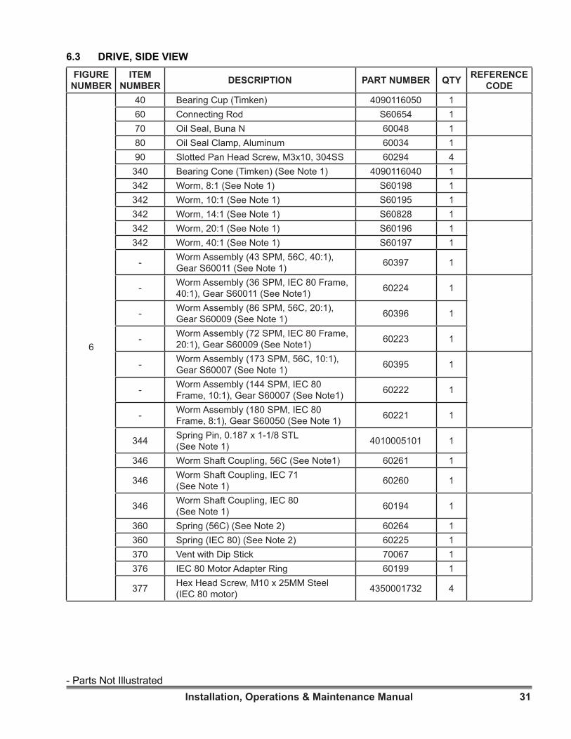
FIGURE NUMBER
ITEM NUMBER DESCRIPTION PART NUMBER QTY REFERENCE
CODE
6
40 Bearing Cup (Timken) 4090116050 160 Connecting Rod S60654 170 Oil Seal, Buna N 60048 180 Oil Seal Clamp, Aluminum 60034 190 Slotted Pan Head Screw, M3x10, 304SS 60294 4
340 Bearing Cone (Timken) (See Note 1) 4090116040 1342 Worm, 8:1 (See Note 1) S60198 1342 Worm, 10:1 (See Note 1) S60195 1342 Worm, 14:1 (See Note 1) S60828 1342 Worm, 20:1 (See Note 1) S60196 1342 Worm, 40:1 (See Note 1) S60197 1
- Worm Assembly (43 SPM, 56C, 40:1), Gear S60011 (See Note 1) 60397 1
- Worm Assembly (36 SPM, IEC 80 Frame, 40:1), Gear S60011 (See Note1) 60224 1
- Worm Assembly (86 SPM, 56C, 20:1), Gear S60009 (See Note 1) 60396 1
- Worm Assembly (72 SPM, IEC 80 Frame, 20:1), Gear S60009 (See Note1) 60223 1
- Worm Assembly (173 SPM, 56C, 10:1), Gear S60007 (See Note 1) 60395 1
- Worm Assembly (144 SPM, IEC 80 Frame, 10:1), Gear S60007 (See Note1) 60222 1
- Worm Assembly (180 SPM, IEC 80 Frame, 8:1), Gear S60050 (See Note 1) 60221 1
344 Spring Pin, 0.187 x 1-1/8 STL (See Note 1) 4010005101 1
346 Worm Shaft Coupling, 56C (See Note1) 60261 1
346 Worm Shaft Coupling, IEC 71 (See Note 1) 60260 1
346 Worm Shaft Coupling, IEC 80 (See Note 1) 60194 1
360 Spring (56C) (See Note 2) 60264 1360 Spring (IEC 80) (See Note 2) 60225 1370 Vent with Dip Stick 70067 1376 IEC 80 Motor Adapter Ring 60199 1
377 Hex Head Screw, M10 x 25MM Steel (IEC 80 motor) 4350001732 4
6.3 DRIVE, SIDE VIEW
- Parts Not Illustrated

32 Installation, Operations & Maintenance Manual
6
390 Motor (1 hp, 1 ph, 1800 rpm, 115/230, 60 hz, 56C) 4112008010 1
390 Motor (1 hp, 3 ph, 1500 rpm, 220/380, 50 hz, 56C) 4112008315 1
390 Motor ( 1hp, 3 ph, 1800 rpm, 230/460, 60 hz, 56C) 4112008310 1
390 Motor (1 hp, 1750 rpm, 90 VDC, PM - TEFC-56C) 4112008610 1
390 Motor (1 hp, W/VAR SPD AC Drive) 60297 1400 Hex Head Screw (3/8-16 x 1) (56C motor) 4050018119 4
400 Hex Head Screw (M10 x 25 mm) (IEC 80 motor) 4350001732 4
410 Flat Washer (3/8) (56C motor) 4040009012 4410 Flat Washer (M10) (IEC 80 motor) 4340005152 4417 Caution, Motor Decal G 60148 1450 Base 61266 1460 Hex Head Screw (M8 x 35 mm) 4350035542 4465 Spring Lock Washer (8 mm) 4340009002 4470 Hex Nut (M8) 4350000042 4
FIGURE NUMBER
ITEM NUMBER DESCRIPTION PART NUMBER QTY REFERENCE
CODE
DRIVE, SIDE VIEW
Note 1:Worm-Gear-Shaft Assembly includes gear (50) worm (342), spring pin (344), spring (360), worm shaft coupling (346), and bearing cone (340). Gear (50) and worm (342) sold only as assembly (343)
Note 2: Part number for 56C motor spring (60264) applies to two-piece worm assembly: worm and motor coupling piece joined together by a spring pin (344). If worm is previous one-piece design (no spring pin), the correct 56C motor spring part number is 60059.
- Parts Not Illustrated
33Installation, Operations & Maintenance Manual
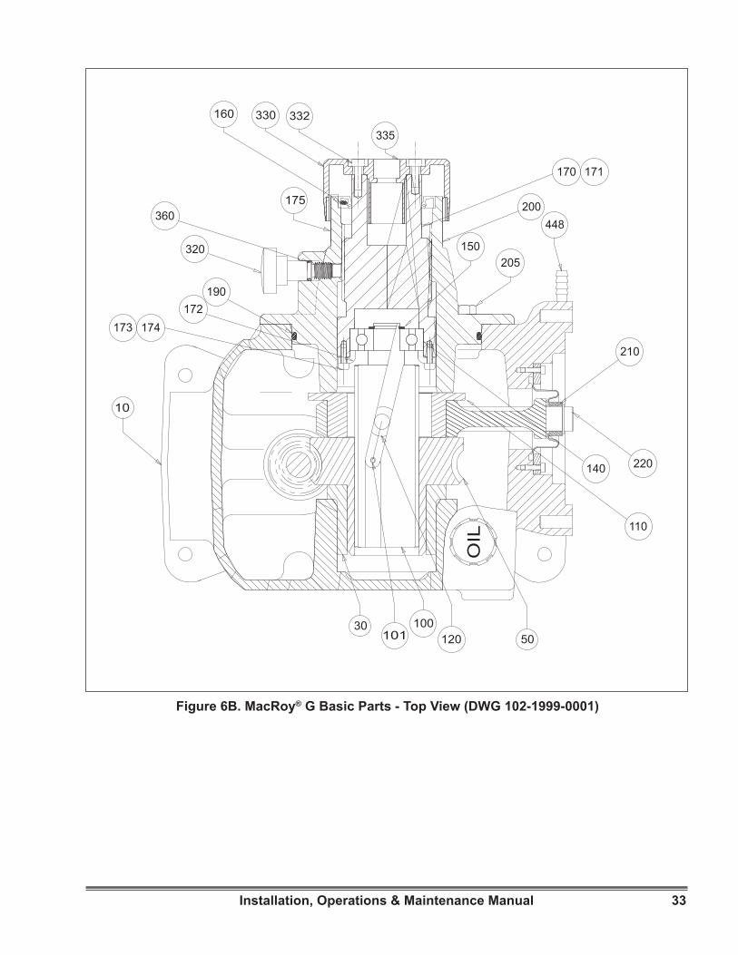
Figure 6B. MacRoy® G Basic Parts - Top View (DWG 102-1999-0001)
OIL
220
175
335
332330160
448
210
110
205
173
360
190
320
172
140
150
170 171
174
10
101100
12030
50
200
34 Installation, Operations & Maintenance Manual
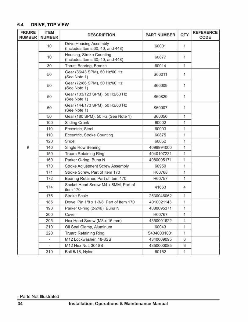
6.4 DRIVE, TOP VIEWFIGURE
NUMBERITEM
NUMBER DESCRIPTION PART NUMBER QTY REFERENCE CODE
6
10 Drive Housing Assembly (Includes Items 30, 40, and 448) 60001 1
10 Housing, Stroke Counting (Includes Items 30, 40, and 448) 60877 1
30 Thrust Bearing, Bronze 60014 1
50 Gear (36/43 SPM), 50 Hz/60 Hz (See Note 1) S60011 1
50 Gear (72/86 SPM), 50 Hz/60 Hz (See Note 1) S60009 1
50 Gear (103/123 SPM), 50 Hz/60 Hz (See Note 1) S60829 1
50 Gear (144/173 SPM), 50 Hz/60 Hz (See Note 1) S60007 1
50 Gear (180 SPM), 50 Hz (See Note 1) S60050 1100 Sliding Crank 60002 1110 Eccentric, Steel 60003 1110 Eccentric, Stroke Counting 60875 1120 Shoe 60052 1140 Single Row Bearing 4099994000 1150 Truarc Retaining Ring 4040107231 1160 Parker O-ring, Buna N 4080095171 1170 Stroke Adjustment Screw Assembly 60950 1171 Stroke Screw, Part of Item 170 H60768 1172 Bearing Retainer, Part of Item 170 H60757 1
174 Socket Head Screw M4 x 8MM, Part of item 170 41663 4
175 Stroke Scale 2530046062 1185 Dowel Pin 1/8 x 1-3/8, Part of Item 170 4010021143 1190 Parker O-ring (2-246), Buna N 4080095371 1200 Cover H60767 1205 Hex Head Screw (M8 x 16 mm) 4350001622 4210 Oil Seal Clamp, Aluminum 60043 1220 Truarc Retaining Ring S4340031001 1
- M12 Lockwasher, 18-8SS 4340009095 6- M12 Hex Nut, 304SS 4350000085 6
310 Ball 5/16, Nylon 60152 1
- Parts Not Illustrated

35Installation, Operations & Maintenance Manual
DRIVE, TOP VIEW
Note 1:Worm-Gear-Shaft Assembly includes gear (50) worm (342), spring pin (344), spring (360), worm shaft coupling (346), and bearing cone (340). Gear (50) and worm (342) sold only as assembly (343)
Note 2: Part number for 56C motor spring (60264) applies to two-piece worm assembly: worm and motor coupling piece joined together by a spring pin (344). If worm is previous one-piece design (no spring pin), the correct 56C motor spring part number is 60059.
DRIVE, TOP VIEW
6
320 Stroke Locking Knob 60398 1322 O-Ring, 2-012 Bunan N 4080109091 1330 Stroke Adjustment Knob 70066 1331 Flat Washer 1/4”, 18.8SS 4040005012 1332 Pan Head Screw #8 x 1-1/2”, 18.8SS 40722 1335 Logo Decal (Stroke Knob) 70022 1448 Tubing Connector (1/4” OD x 1/4” ID) 4020479028 1
- Gear Oil (AGMA 5 EP, ZURN EP95) - 1 Quart Can 4070152010 3
FIGURE NUMBER
ITEM NUMBER DESCRIPTION PART NUMBER QTY REFERENCE
CODE
- Parts Not Illustrated
36 Installation, Operations & Maintenance Manual
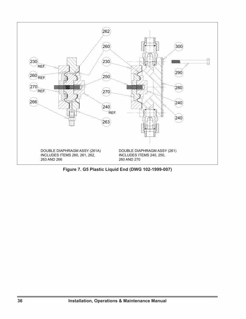
Figure 7. G5 Plastic Liquid End (DWG 102-1999-007)
230
240
250
260
262
270280
290
300
240
230
260
240
270REF.
REF.
REF.
REF.
266
263
DOUBLE DIAPHRAGM ASSY (261A)INCLUDES ITEMS 260, 261, 262,263 AND 266
DOUBLE DIAPHRAGM ASSY (261)INCLUDES ITEMS 240, 250, 260 AND 270
37Installation, Operations & Maintenance Manual
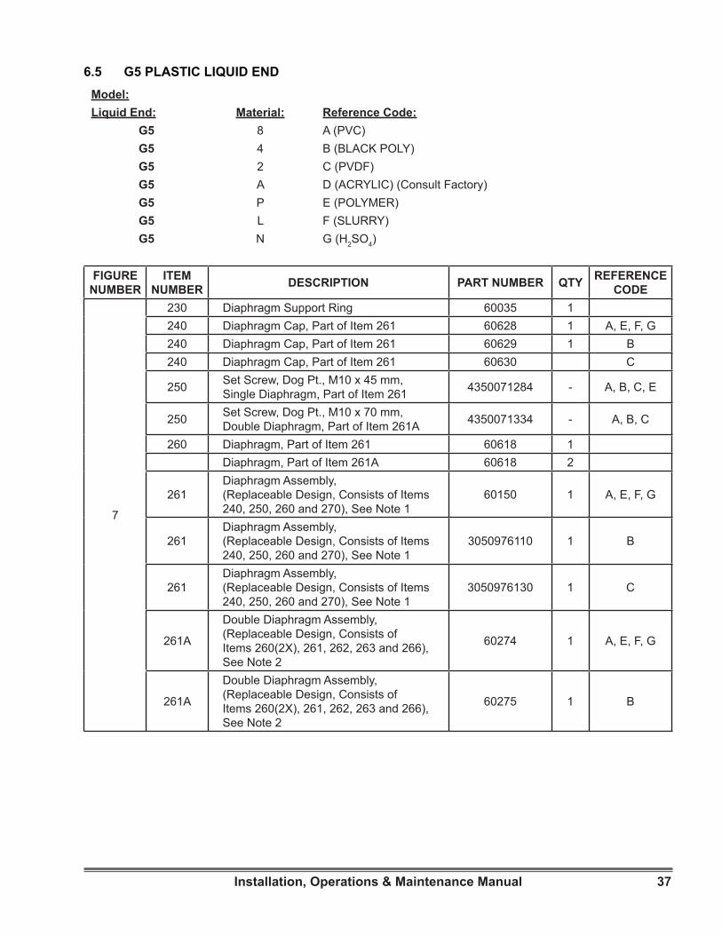
Model:Liquid End: Material: Reference Code:
G5 8 A (PVC)G5 4 B (BLACK POLY)G5 2 C (PVDF)G5 A D (ACRYLIC) (Consult Factory)G5 P E (POLYMER)G5 L F (SLURRY)G5 N G (H2SO4)
6.5 G5 PLASTIC LIQUID END
FIGURE NUMBER
ITEM NUMBER DESCRIPTION PART NUMBER QTY REFERENCE
CODE
7
230 Diaphragm Support Ring 60035 1240 Diaphragm Cap, Part of Item 261 60628 1 A, E, F, G240 Diaphragm Cap, Part of Item 261 60629 1 B240 Diaphragm Cap, Part of Item 261 60630 C
250 Set Screw, Dog Pt., M10 x 45 mm, Single Diaphragm, Part of Item 261 4350071284 - A, B, C, E
250 Set Screw, Dog Pt., M10 x 70 mm, Double Diaphragm, Part of Item 261A 4350071334 - A, B, C
260 Diaphragm, Part of Item 261 60618 1Diaphragm, Part of Item 261A 60618 2
261Diaphragm Assembly, (Replaceable Design, Consists of Items 240, 250, 260 and 270), See Note 1
60150 1 A, E, F, G
261Diaphragm Assembly, (Replaceable Design, Consists of Items 240, 250, 260 and 270), See Note 1
3050976110 1 B
261Diaphragm Assembly, (Replaceable Design, Consists of Items 240, 250, 260 and 270), See Note 1
3050976130 1 C
261A
Double Diaphragm Assembly, (Replaceable Design, Consists of Items 260(2X), 261, 262, 263 and 266), See Note 2
60274 1 A, E, F, G
261A
Double Diaphragm Assembly, (Replaceable Design, Consists of Items 260(2X), 261, 262, 263 and 266), See Note 2
60275 1 B
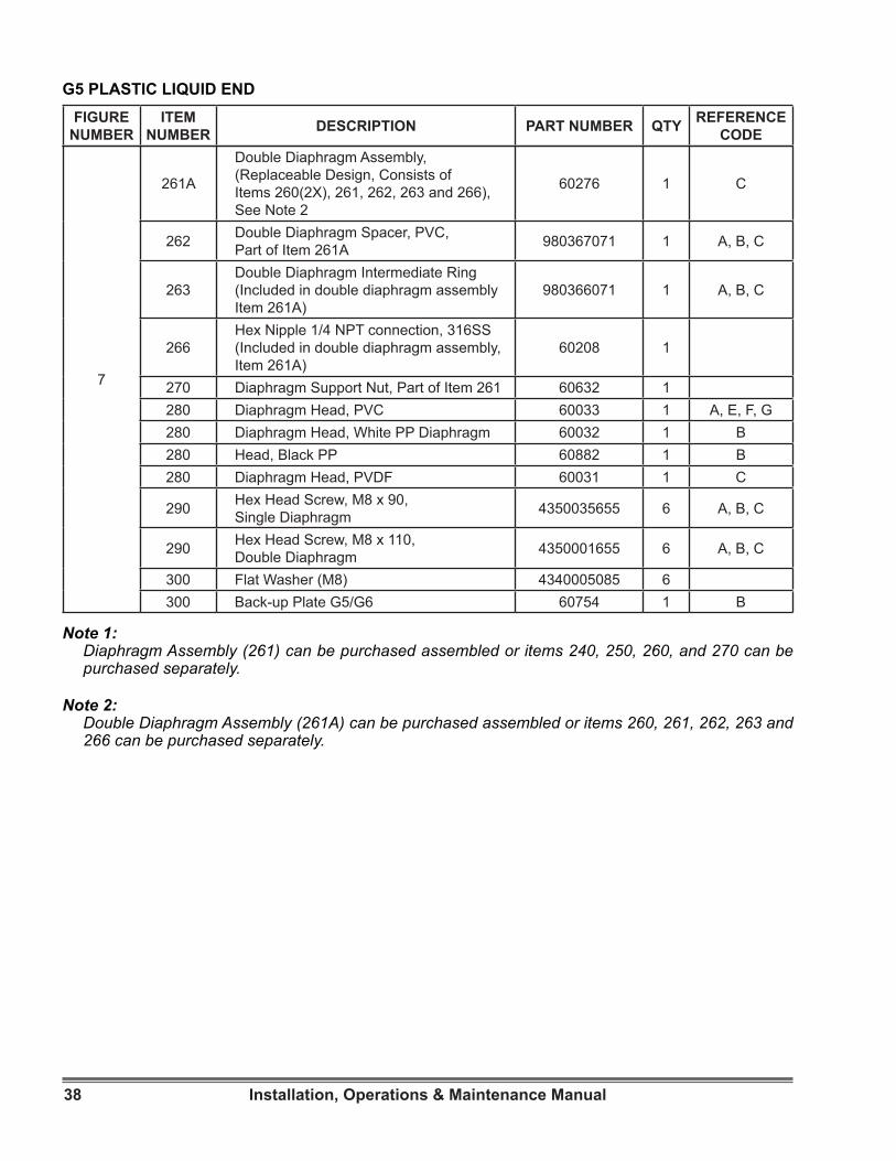
38 Installation, Operations & Maintenance Manual
G5 PLASTIC LIQUID ENDFIGURE
NUMBERITEM
NUMBER DESCRIPTION PART NUMBER QTY REFERENCE CODE
7
261A
Double Diaphragm Assembly, (Replaceable Design, Consists of Items 260(2X), 261, 262, 263 and 266), See Note 2
60276 1 C
262 Double Diaphragm Spacer, PVC, Part of Item 261A 980367071 1 A, B, C
263Double Diaphragm Intermediate Ring (Included in double diaphragm assembly Item 261A)
980366071 1 A, B, C
266Hex Nipple 1/4 NPT connection, 316SS (Included in double diaphragm assembly, Item 261A)
60208 1
270 Diaphragm Support Nut, Part of Item 261 60632 1280 Diaphragm Head, PVC 60033 1 A, E, F, G280 Diaphragm Head, White PP Diaphragm 60032 1 B 280 Head, Black PP 60882 1 B280 Diaphragm Head, PVDF 60031 1 C
290 Hex Head Screw, M8 x 90, Single Diaphragm 4350035655 6 A, B, C
290 Hex Head Screw, M8 x 110, Double Diaphragm 4350001655 6 A, B, C
300 Flat Washer (M8) 4340005085 6300 Back-up Plate G5/G6 60754 1 B
Note 1:Diaphragm Assembly (261) can be purchased assembled or items 240, 250, 260, and 270 can be purchased separately.
Note 2: Double Diaphragm Assembly (261A) can be purchased assembled or items 260, 261, 262, 263 and 266 can be purchased separately.
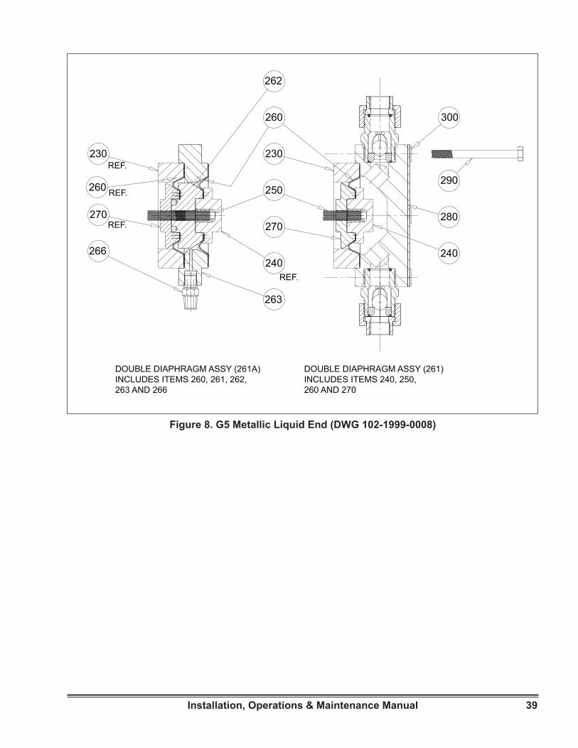
39Installation, Operations & Maintenance Manual
Figure 8. G5 Metallic Liquid End (DWG 102-1999-0008)
230
240
250
260
262
270280
290
300
230
260
240
270REF.
REF.
REF.
REF.
266
263
DOUBLE DIAPHRAGM ASSY (261A)INCLUDES ITEMS 260, 261, 262,263 AND 266
DOUBLE DIAPHRAGM ASSY (261)INCLUDES ITEMS 240, 250, 260 AND 270
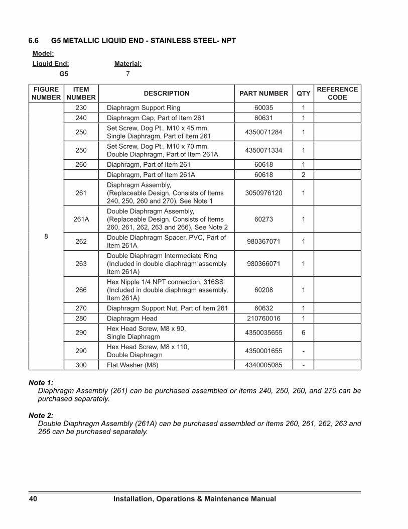
40 Installation, Operations & Maintenance Manual
Model:Liquid End: Material:
G5 7
6.6 G5 METALLIC LIQUID END - STAINLESS STEEL- NPT
FIGURE NUMBER
ITEM NUMBER DESCRIPTION PART NUMBER QTY REFERENCE
CODE
8
230 Diaphragm Support Ring 60035 1240 Diaphragm Cap, Part of Item 261 60631 1
250 Set Screw, Dog Pt., M10 x 45 mm, Single Diaphragm, Part of Item 261 4350071284 1
250 Set Screw, Dog Pt., M10 x 70 mm, Double Diaphragm, Part of Item 261A 4350071334 1
260 Diaphragm, Part of Item 261 60618 1Diaphragm, Part of Item 261A 60618 2
261Diaphragm Assembly, (Replaceable Design, Consists of Items 240, 250, 260 and 270), See Note 1
3050976120 1
261ADouble Diaphragm Assembly, (Replaceable Design, Consists of Items 260, 261, 262, 263 and 266), See Note 2
60273 1
262 Double Diaphragm Spacer, PVC, Part of Item 261A 980367071 1
263Double Diaphragm Intermediate Ring (Included in double diaphragm assembly Item 261A)
980366071 1
266Hex Nipple 1/4 NPT connection, 316SS (Included in double diaphragm assembly, Item 261A)
60208 1
270 Diaphragm Support Nut, Part of Item 261 60632 1280 Diaphragm Head 210760016 1
290 Hex Head Screw, M8 x 90, Single Diaphragm 4350035655 6
290 Hex Head Screw, M8 x 110, Double Diaphragm 4350001655 -
300 Flat Washer (M8) 4340005085 -
Note 1:Diaphragm Assembly (261) can be purchased assembled or items 240, 250, 260, and 270 can be purchased separately.
Note 2: Double Diaphragm Assembly (261A) can be purchased assembled or items 260, 261, 262, 263 and 266 can be purchased separately.
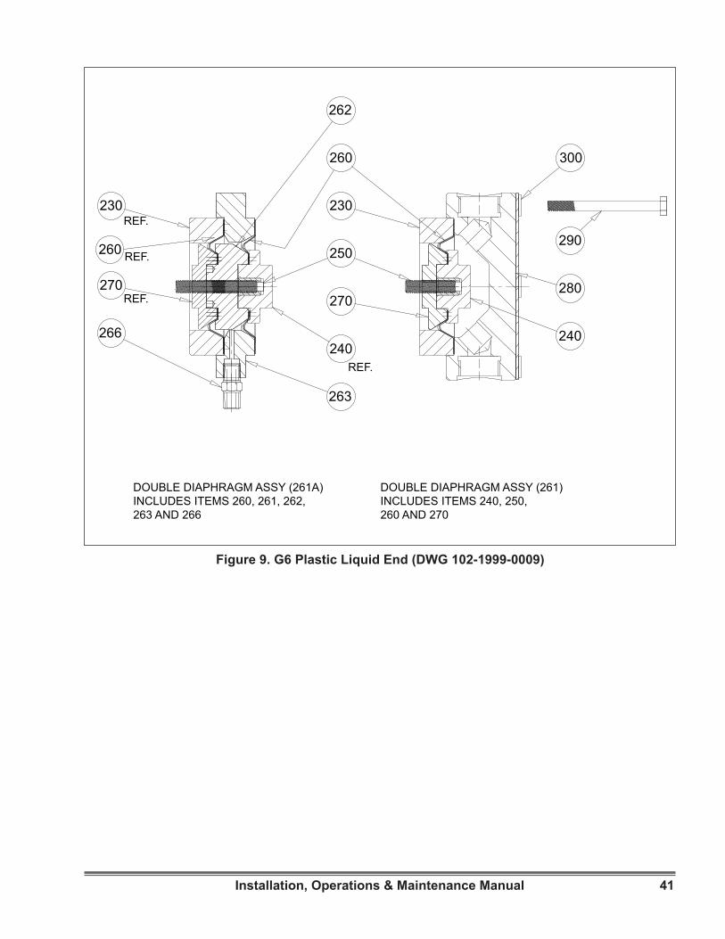
41Installation, Operations & Maintenance Manual
Figure 9. G6 Plastic Liquid End (DWG 102-1999-0009)
230
240
250
260
262
270280
290
300
230
260
240
270REF.
REF.
REF.
REF.
266
263
DOUBLE DIAPHRAGM ASSY (261A)INCLUDES ITEMS 260, 261, 262,263 AND 266
DOUBLE DIAPHRAGM ASSY (261)INCLUDES ITEMS 240, 250, 260 AND 270
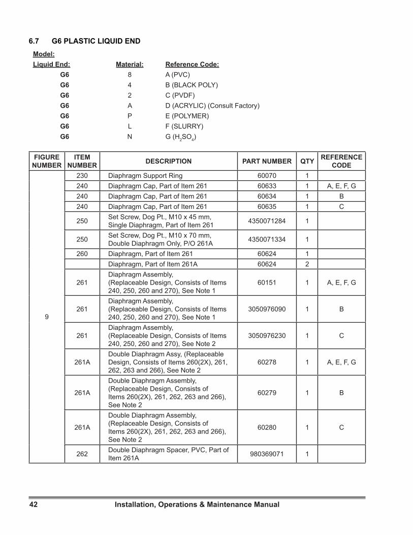
42 Installation, Operations & Maintenance Manual
Model:Liquid End: Material: Reference Code:
G6 8 A (PVC)G6 4 B (BLACK POLY)G6 2 C (PVDF)G6 A D (ACRYLIC) (Consult Factory)G6 P E (POLYMER)G6 L F (SLURRY)G6 N G (H2SO4)
6.7 G6 PLASTIC LIQUID END
FIGURE NUMBER
ITEM NUMBER DESCRIPTION PART NUMBER QTY REFERENCE
CODE
9
230 Diaphragm Support Ring 60070 1240 Diaphragm Cap, Part of Item 261 60633 1 A, E, F, G240 Diaphragm Cap, Part of Item 261 60634 1 B240 Diaphragm Cap, Part of Item 261 60635 1 C
250 Set Screw, Dog Pt., M10 x 45 mm, Single Diaphragm, Part of Item 261 4350071284 1
250 Set Screw, Dog Pt., M10 x 70 mm, Double Diaphragm Only, P/O 261A 4350071334 1
260 Diaphragm, Part of Item 261 60624 1Diaphragm, Part of Item 261A 60624 2
261Diaphragm Assembly, (Replaceable Design, Consists of Items 240, 250, 260 and 270), See Note 1
60151 1 A, E, F, G
261Diaphragm Assembly, (Replaceable Design, Consists of Items 240, 250, 260 and 270), See Note 1
3050976090 1 B
261Diaphragm Assembly, (Replaceable Design, Consists of Items 240, 250, 260 and 270), See Note 2
3050976230 1 C
261ADouble Diaphragm Assy, (Replaceable Design, Consists of Items 260(2X), 261, 262, 263 and 266), See Note 2
60278 1 A, E, F, G
261A
Double Diaphragm Assembly, (Replaceable Design, Consists of Items 260(2X), 261, 262, 263 and 266), See Note 2
60279 1 B
261A
Double Diaphragm Assembly, (Replaceable Design, Consists of Items 260(2X), 261, 262, 263 and 266), See Note 2
60280 1 C
262 Double Diaphragm Spacer, PVC, Part of Item 261A 980369071 1
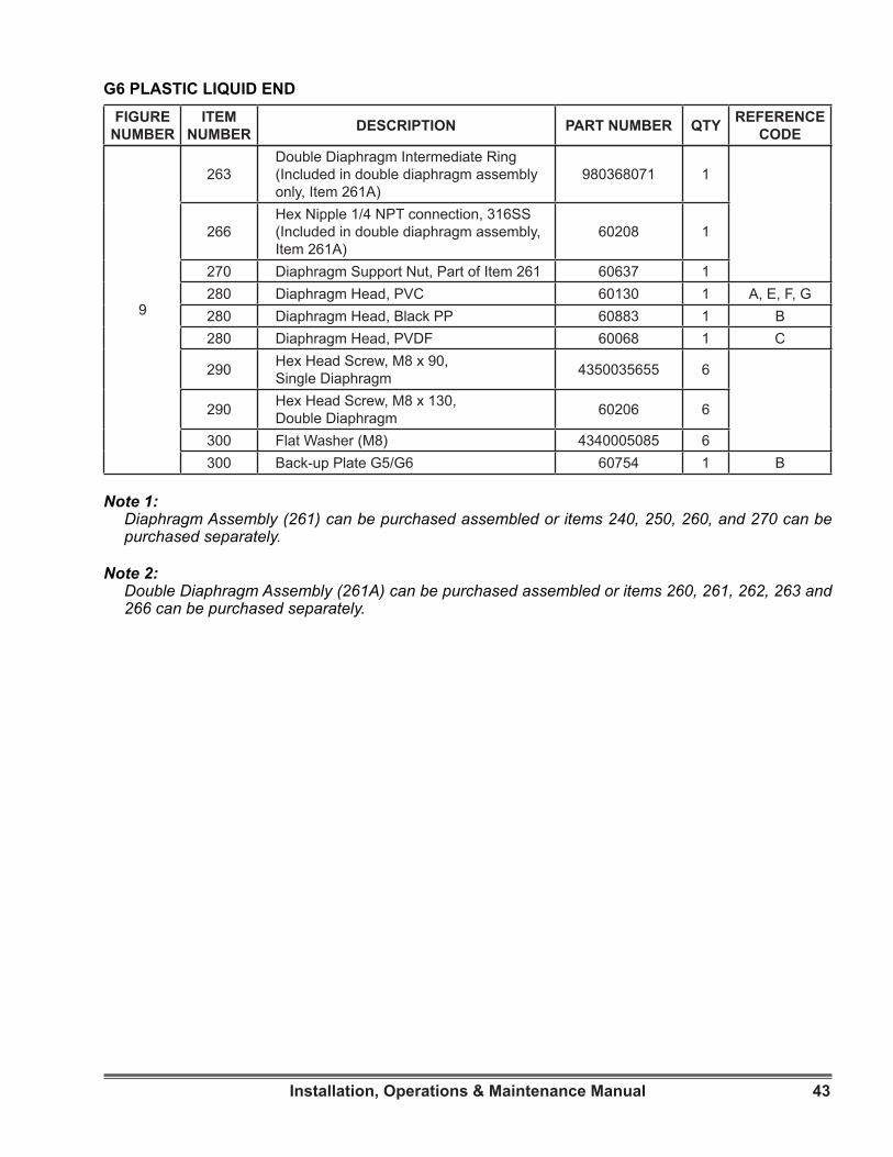
43Installation, Operations & Maintenance Manual
G6 PLASTIC LIQUID END
9
263Double Diaphragm Intermediate Ring (Included in double diaphragm assembly only, Item 261A)
980368071 1
266Hex Nipple 1/4 NPT connection, 316SS (Included in double diaphragm assembly, Item 261A)
60208 1
270 Diaphragm Support Nut, Part of Item 261 60637 1280 Diaphragm Head, PVC 60130 1 A, E, F, G280 Diaphragm Head, Black PP 60883 1 B280 Diaphragm Head, PVDF 60068 1 C
290 Hex Head Screw, M8 x 90, Single Diaphragm 4350035655 6
290 Hex Head Screw, M8 x 130, Double Diaphragm 60206 6
300 Flat Washer (M8) 4340005085 6300 Back-up Plate G5/G6 60754 1 B
FIGURE NUMBER
ITEM NUMBER DESCRIPTION PART NUMBER QTY REFERENCE
CODE
Note 1:Diaphragm Assembly (261) can be purchased assembled or items 240, 250, 260, and 270 can be purchased separately.
Note 2: Double Diaphragm Assembly (261A) can be purchased assembled or items 260, 261, 262, 263 and 266 can be purchased separately.
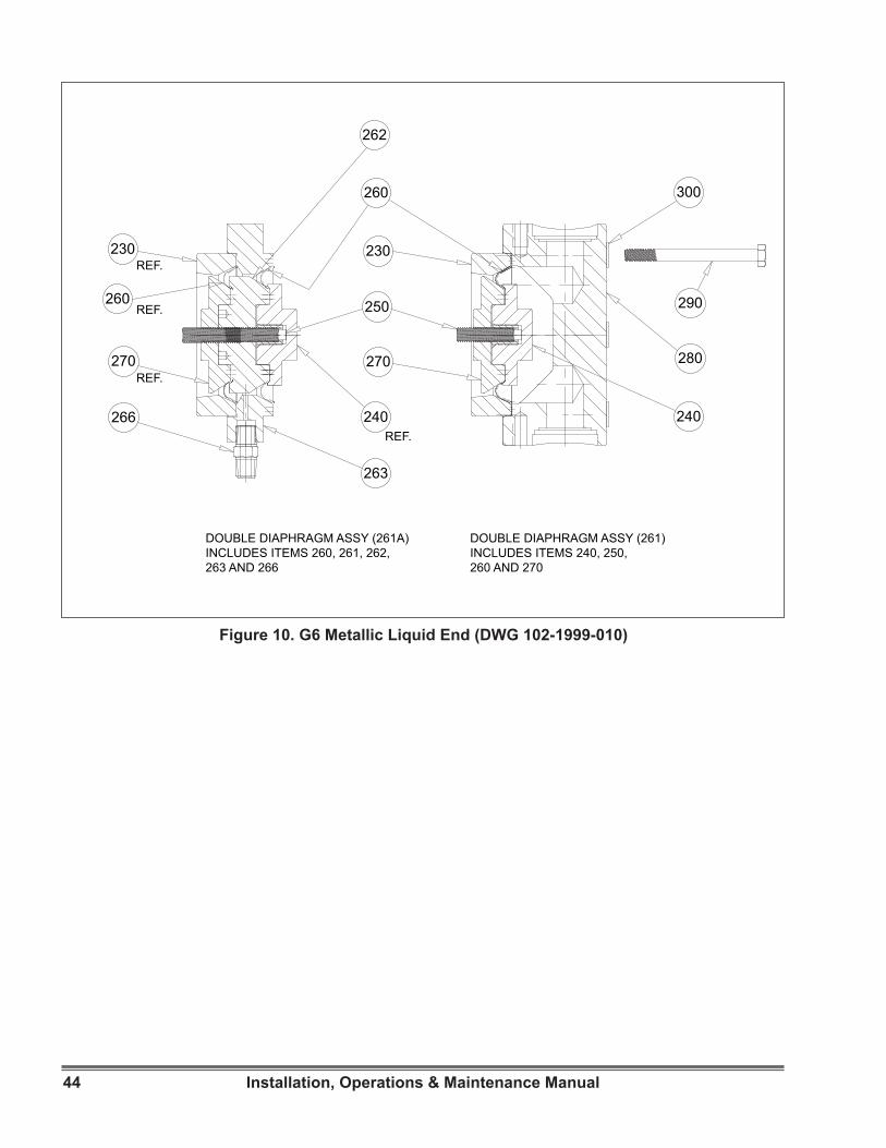
44 Installation, Operations & Maintenance Manual
Figure 10. G6 Metallic Liquid End (DWG 102-1999-010)
DOUBLE DIAPHRAGM ASSY (261A)INCLUDES ITEMS 260, 261, 262,263 AND 266
DOUBLE DIAPHRAGM ASSY (261)INCLUDES ITEMS 240, 250, 260 AND 270
230
270
266
263
240
260
REF.
REF.
REF.
REF.270
250
230
260
262
300
290
280
240
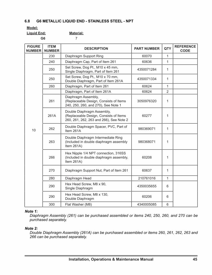
45Installation, Operations & Maintenance Manual
Model:Liquid End: Material:
G6 7
6.8 G6 METALLIC LIQUID END - STAINLESS STEEL - NPT
FIGURE NUMBER
ITEM NUMBER DESCRIPTION PART NUMBER QTY REFERENCE
CODE
10
230 Diaphragm Support Ring 60070 1240 Diaphragm Cap, Part of Item 261 60636 1
250 Set Screw, Dog Pt., M10 x 45 mm, Single Diaphragm, Part of Item 261 4350071284 1
250 Set Screw, Dog Pt., M10 x 70 mm, Double Diaphragm, Part of Item 261A 4350071334 1
260 Diaphragm, Part of Item 261 60624 1Diaphragm, Part of Item 261A 60624 2
261Diaphragm Assembly, (Replaceable Design, Consists of Items 240, 250, 260, and 270), See Note 1
3050976320 1
261ADouble Diaphragm Assembly, (Replaceable Design, Consists of Items 260, 261, 262, 263 and 266), See Note 2
60277 1
262 Double Diaphragm Spacer, PVC, Part of Item 261A 980369071 1
263Double Diaphragm Intermediate Ring (Included in double diaphragm assembly Item 261A)
980368071 1
266Hex Nipple 1/4 NPT connection, 316SS (Included in double diaphragm assembly, Item 261A)
60208 1
270 Diaphragm Support Nut, Part of Item 261 60637 1
280 Diaphragm Head 210761016 1
290 Hex Head Screw, M8 x 90, Single Diaphragm 4350035655 6
290 Hex Head Screw, M8 x 130, Double Diaphragm 60206 6
300 Flat Washer (M8) 4340005085 6
Note 1:Diaphragm Assembly (261) can be purchased assembled or items 240, 250, 260, and 270 can be purchased separately.
Note 2: Double Diaphragm Assembly (261A) can be purchased assembled or items 260, 261, 262, 263 and 266 can be purchased separately.
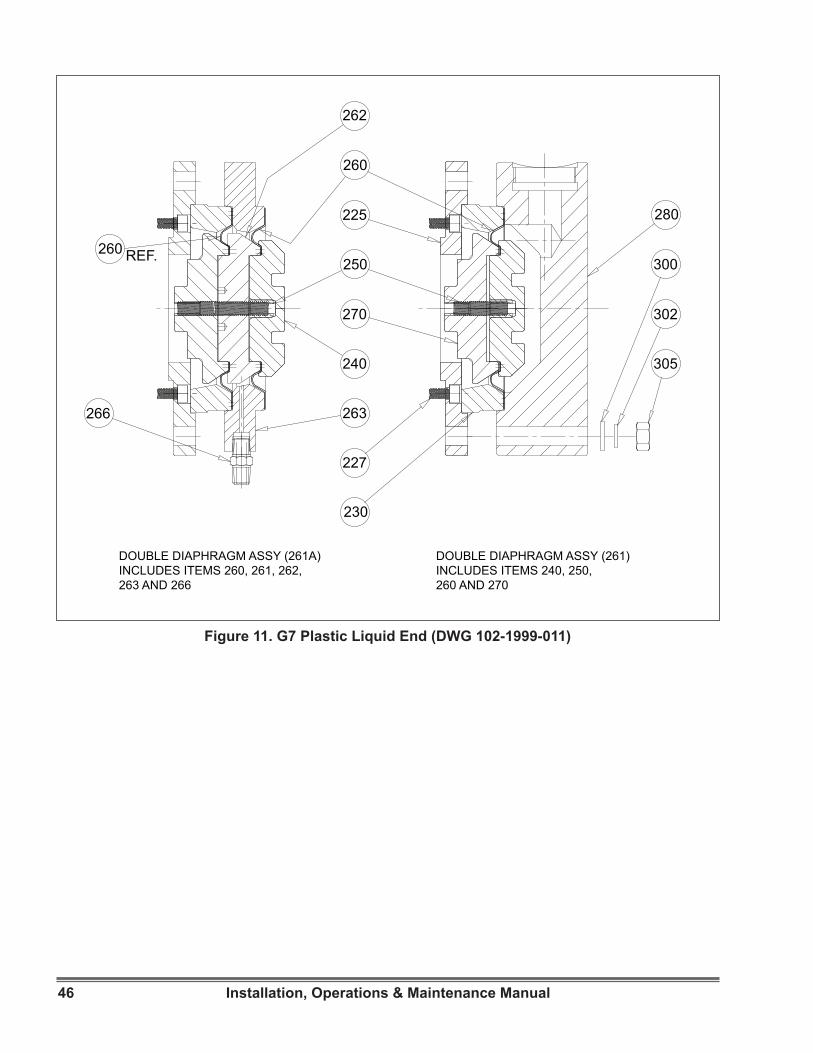
46 Installation, Operations & Maintenance Manual
Figure 11. G7 Plastic Liquid End (DWG 102-1999-011)
260
262
225
250
270
240
263266
227
230
305
302
300
280
260 REF.
DOUBLE DIAPHRAGM ASSY (261A)INCLUDES ITEMS 260, 261, 262,263 AND 266
DOUBLE DIAPHRAGM ASSY (261)INCLUDES ITEMS 240, 250, 260 AND 270
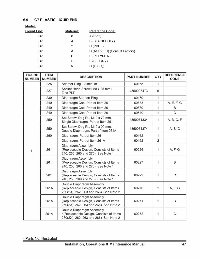
47Installation, Operations & Maintenance Manual
Model:Liquid End: Material: Reference Code:
G7 8 A (PVC)G7 4 B (BLACK POLY)G7 2 C (PVDF)G7 A D (ACRYLIC) (Consult Factory)G7 P E (POLYMER)G7 L F (SLURRY)G7 N G (H2SO4)
6.9 G7 PLASTIC LIQUID END
FIGURE NUMBER
ITEM NUMBER DESCRIPTION PART NUMBER QTY REFERENCE
CODE
11
225 Adapter Ring, Aluminum 60165 1
227 Socket Head Screw (M8 x 25 mm), Zinc PLT 4350003473 6
230 Diaphragm Support Ring 60159 1240 Diaphragm Cap, Part of Item 261 60638 1 A, E, F, G240 Diaphragm Cap, Part of Item 261 60639 1 B240 Diaphragm Cap, Part of Item 261 60640 1 C
250 Set Screw, Dog Pt., M10 x 70 mm, Single Diaphragm, Part of Item 261 4350071334 1 A, B, C, F
250 Set Screw, Dog Pt., M10 x 90 mm, Double Diaphragm, Part of Item 261A 4350071374 1 A, B, C
260 Diaphragm, Part of Item 261 60162 1Diaphragm, Part of Item 261A 60162 2
261Diaphragm Assembly, (Replaceable Design, Consists of Items 240, 250, 260 and 270), See Note 1
60226 1 A, F, G
261Diaphragm Assembly, (Replaceable Design, Consists of Items 240, 250, 260 and 270), See Note 1
60227 1 B
261Diaphragm Assembly, (Replaceable Design, Consists of Items 240, 250, 260 and 270), See Note 1
60229 1 C
261ADouble Diaphragm Assembly, (Replaceable Design, Consists of Items 260(2X), 262, 263 and 266), See Note 2
60270 1 A, F, G
261ADouble Diaphragm Assembly, (Replaceable Design, Consists of Items 260(2X), 262, 263 and 266), See Note 2
60271 1 B
261ADouble Diaphragm Assembly, n(Replaceable Design, Consists of Items 260(2X), 262, 263 and 266), See Note 2
60272 1 C
- Parts Not Illustrated
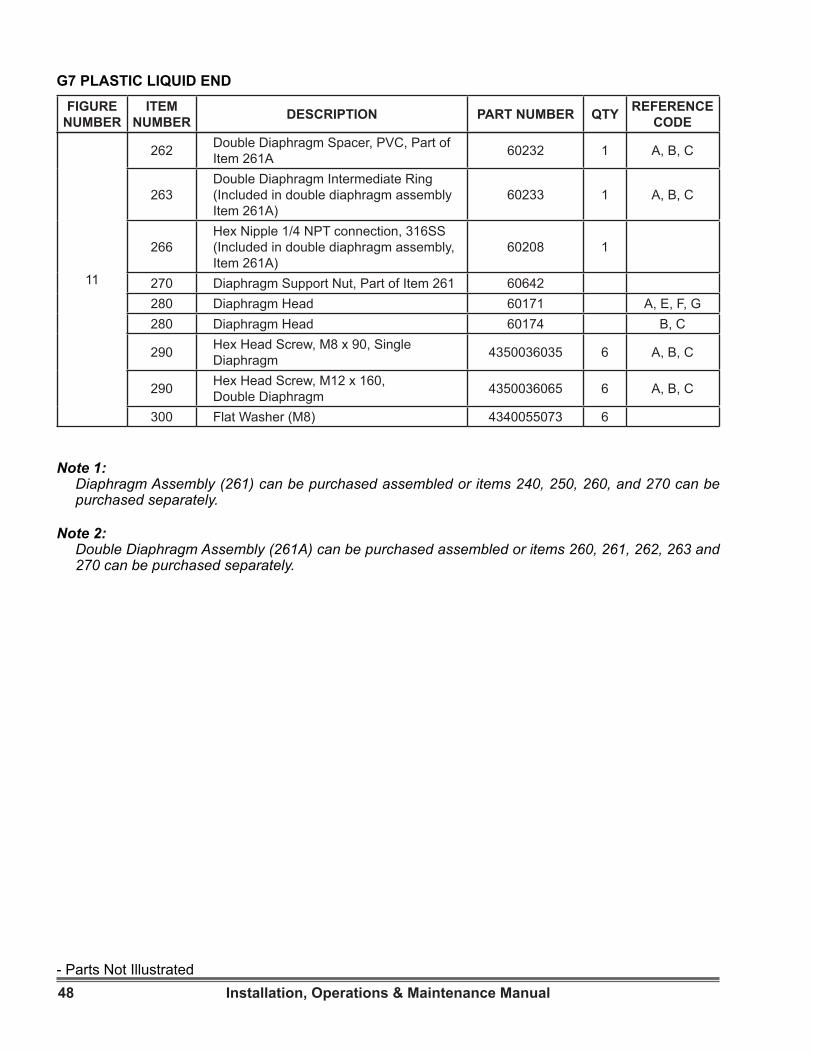
48 Installation, Operations & Maintenance Manual
G7 PLASTIC LIQUID ENDFIGURE
NUMBERITEM
NUMBER DESCRIPTION PART NUMBER QTY REFERENCE CODE
11
262 Double Diaphragm Spacer, PVC, Part of Item 261A 60232 1 A, B, C
263Double Diaphragm Intermediate Ring (Included in double diaphragm assembly Item 261A)
60233 1 A, B, C
266Hex Nipple 1/4 NPT connection, 316SS (Included in double diaphragm assembly, Item 261A)
60208 1
270 Diaphragm Support Nut, Part of Item 261 60642280 Diaphragm Head 60171 A, E, F, G280 Diaphragm Head 60174 B, C
290 Hex Head Screw, M8 x 90, Single Diaphragm 4350036035 6 A, B, C
290 Hex Head Screw, M12 x 160, Double Diaphragm 4350036065 6 A, B, C
300 Flat Washer (M8) 4340055073 6
Note 1:Diaphragm Assembly (261) can be purchased assembled or items 240, 250, 260, and 270 can be purchased separately.
Note 2: Double Diaphragm Assembly (261A) can be purchased assembled or items 260, 261, 262, 263 and 270 can be purchased separately.
- Parts Not Illustrated
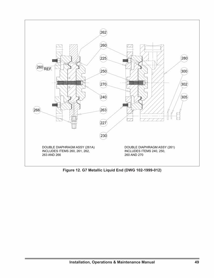
49Installation, Operations & Maintenance Manual
Figure 12. G7 Metallic Liquid End (DWG 102-1999-012)
260
262
225
250
270
240
263266
227
230
305
302
300
280
260 REF.
DOUBLE DIAPHRAGM ASSY (261A)INCLUDES ITEMS 260, 261, 262,263 AND 266
DOUBLE DIAPHRAGM ASSY (261)INCLUDES ITEMS 240, 250, 260 AND 270
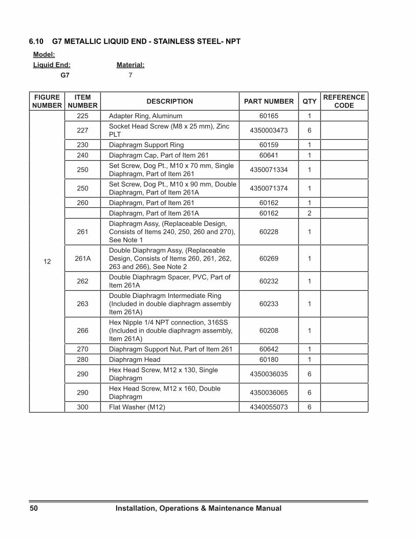
50 Installation, Operations & Maintenance Manual
Model:Liquid End: Material:
G7 7
6.10 G7 METALLIC LIQUID END - STAINLESS STEEL- NPT
FIGURE NUMBER
ITEM NUMBER DESCRIPTION PART NUMBER QTY REFERENCE
CODE
12
225 Adapter Ring, Aluminum 60165 1
227 Socket Head Screw (M8 x 25 mm), Zinc PLT 4350003473 6
230 Diaphragm Support Ring 60159 1240 Diaphragm Cap, Part of Item 261 60641 1
250 Set Screw, Dog Pt., M10 x 70 mm, Single Diaphragm, Part of Item 261 4350071334 1
250 Set Screw, Dog Pt., M10 x 90 mm, Double Diaphragm, Part of Item 261A 4350071374 1
260 Diaphragm, Part of Item 261 60162 1Diaphragm, Part of Item 261A 60162 2
261Diaphragm Assy, (Replaceable Design, Consists of Items 240, 250, 260 and 270), See Note 1
60228 1
261ADouble Diaphragm Assy, (Replaceable Design, Consists of Items 260, 261, 262, 263 and 266), See Note 2
60269 1
262 Double Diaphragm Spacer, PVC, Part of Item 261A 60232 1
263Double Diaphragm Intermediate Ring (Included in double diaphragm assembly Item 261A)
60233 1
266Hex Nipple 1/4 NPT connection, 316SS (Included in double diaphragm assembly, Item 261A)
60208 1
270 Diaphragm Support Nut, Part of Item 261 60642 1280 Diaphragm Head 60180 1
290 Hex Head Screw, M12 x 130, Single Diaphragm 4350036035 6
290 Hex Head Screw, M12 x 160, Double Diaphragm 4350036065 6
300 Flat Washer (M12) 4340055073 6

51Installation, Operations & Maintenance Manual
Figure 13. ( A to D ) Check Valve Parts (DWG 102-1999-002)
442
437
437
413
422
422
419
419
420
420
424
424
439
441
441
435
435
Figure 13B. Model G5 Metallic Check ValveParts (Item Number 425)
Figure 13C. Model G6 & G7 Plastic Check Valve Parts (Item Number 425)
Figure 13D. Model G6 & G7 Metallic CheckValve Parts (Item Number 425)
Figure 13A. Model G5 Plastic Check ValveParts (Item Number 425)
445
445
435
435
422
422
419
419420
420
424
424
419
DISCHARGE
SUCTION
445
435
419420
422
419
424
419
445
435420
422
419
419
424
DISCHARGEDISCHARGE
SUCTIONSUCTION
445
419
422
445
420
420
422
421
421
419
424
424DISCHARGE
SUCTION

52 Installation, Operations & Maintenance Manual
Figure 13E. Model G5 Slurry Check Valve Parts (Item Number 425)
Figure 13F. Model G5, G6, and G7 PolymerCheck Valve Parts (Item Number 425)
Figure 13G. Model G6 & G7 Slurry Check Valve Parts (Item Number 425)
424
445
419
419 420
424426
420
419
419
445
421
426
421
DISCHARGE
SUCTION 445
435
420
422
419
419
424
435445
422
426
423
419
419
425
420
POLYMER DISCHARGE CHECK
POLYMER SUCTION
Figure 13. ( E to G ) Check Valve Parts (DWG 102-1999-002)
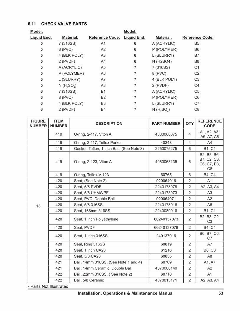
53Installation, Operations & Maintenance Manual
Model:Liquid End: Material: Reference Code:
5 7 (316SS) A15 8 (PVC) A25 4 (BLK POLY) A35 2 (PVDF) A45 A (ACRYLIC) A55 P (POLYMER) A65 L (SLURRY) A75 N (H2SO4) A86 7 (316SS) B16 8 (PVC) B26 4 (BLK POLY) B36 2 (PVDF) B4
6.11 CHECK VALVE PARTSModel:Liquid End: Material: Reference Code:
6 A (ACRYLIC) B56 P (POLYMER) B66 L (SLURRY) B76 N (H2SO4) B87 7 (316SS) C17 8 (PVC) C27 4 (BLK POLY) C37 2 (PVDF) C47 A (ACRYLIC) C57 P (POLYMER) C67 L (SLURRY) C77 N (H2SO4) C8
FIGURE NUMBER
ITEM NUMBER DESCRIPTION PART NUMBER QTY REFERENCE
CODE
13
419 O-ring, 2-117, Viton A 4080068075 4 A1, A2, A3, A6, A7, A8
419 O-ring, 2-117, Teflex Parker 40348 4 A4419 Gasket, Teflon, 1 inch Ball, (See Note 3) 2250075275 6 B1, C1
419 O-ring, 2-123, Viton A 4080068135 6
B2, B3, B6, B7, C2, C3, C6, C7, B8,
C8419 O-ring, Teflex-V-123 60765 6 B4, C4420 Seat, (See Note 2) 920064016 2 A1420 Seat, 5/8 PVDF 2240173078 2 A2, A3, A4420 Seat, 5/8 UHMWPE 2240173073 2 A3420 Seat, PVC, Double Ball 920064071 2 A2420 Seat, 5/8 316SS 2240173016 2 A6420 Seat, 166mm 316SS 2240089016 2 B1, C1
420 Seat, 1 inch Polyethylene 60240137073 2 B2, B3, C2, C3
420 Seat, PVDF 60240137078 2 B4, C4
420 Seat, 1 inch 316SS 240137016 2 B6, B7, C6, C7
420 Seal, Ring 316SS 60819 2 A7420 Seat, 1 inch CA20 61216 2 B8, C8420 Seat, 5/8 CA20 60855 2 A8421 Ball, 14mm 316SS, (See Note 1 and 4) 60709 2 A1, A7421 Ball, 14mm Ceramic, Double Ball 4370000140 2 A2422 Ball, 22mm 316SS, ( See Note 2) 60710 2 A1422 Ball, 5/8 Ceramic 4070015171 2 A2, A3, A4
- Parts Not Illustrated
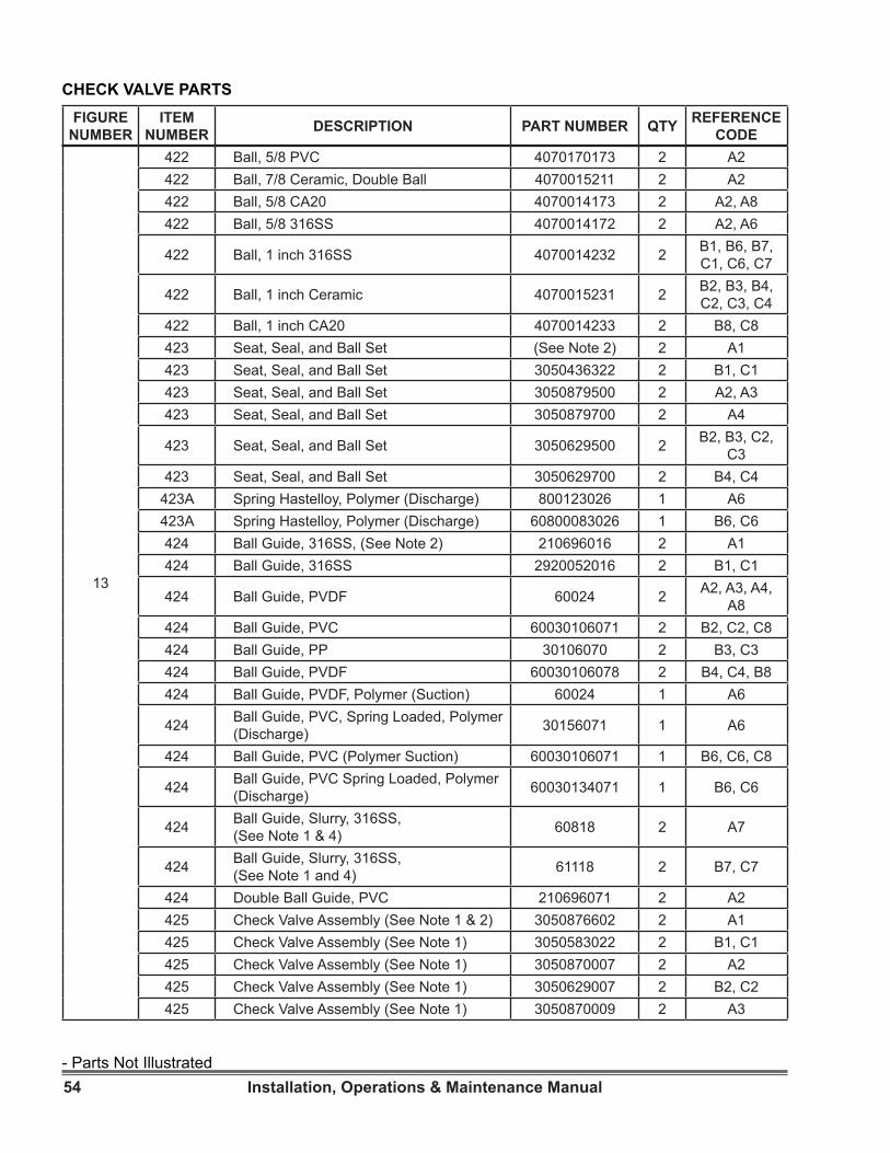
54 Installation, Operations & Maintenance Manual
CHECK VALVE PARTSFIGURE
NUMBERITEM
NUMBER DESCRIPTION PART NUMBER QTY REFERENCE CODE
13
422 Ball, 5/8 PVC 4070170173 2 A2422 Ball, 7/8 Ceramic, Double Ball 4070015211 2 A2422 Ball, 5/8 CA20 4070014173 2 A2, A8422 Ball, 5/8 316SS 4070014172 2 A2, A6
422 Ball, 1 inch 316SS 4070014232 2 B1, B6, B7, C1, C6, C7
422 Ball, 1 inch Ceramic 4070015231 2 B2, B3, B4, C2, C3, C4
422 Ball, 1 inch CA20 4070014233 2 B8, C8423 Seat, Seal, and Ball Set (See Note 2) 2 A1423 Seat, Seal, and Ball Set 3050436322 2 B1, C1423 Seat, Seal, and Ball Set 3050879500 2 A2, A3423 Seat, Seal, and Ball Set 3050879700 2 A4
423 Seat, Seal, and Ball Set 3050629500 2 B2, B3, C2, C3
423 Seat, Seal, and Ball Set 3050629700 2 B4, C4423A Spring Hastelloy, Polymer (Discharge) 800123026 1 A6423A Spring Hastelloy, Polymer (Discharge) 60800083026 1 B6, C6424 Ball Guide, 316SS, (See Note 2) 210696016 2 A1424 Ball Guide, 316SS 2920052016 2 B1, C1
424 Ball Guide, PVDF 60024 2 A2, A3, A4, A8
424 Ball Guide, PVC 60030106071 2 B2, C2, C8424 Ball Guide, PP 30106070 2 B3, C3424 Ball Guide, PVDF 60030106078 2 B4, C4, B8424 Ball Guide, PVDF, Polymer (Suction) 60024 1 A6
424 Ball Guide, PVC, Spring Loaded, Polymer (Discharge) 30156071 1 A6
424 Ball Guide, PVC (Polymer Suction) 60030106071 1 B6, C6, C8
424 Ball Guide, PVC Spring Loaded, Polymer (Discharge) 60030134071 1 B6, C6
424 Ball Guide, Slurry, 316SS, (See Note 1 & 4) 60818 2 A7
424 Ball Guide, Slurry, 316SS, (See Note 1 and 4) 61118 2 B7, C7
424 Double Ball Guide, PVC 210696071 2 A2425 Check Valve Assembly (See Note 1 & 2) 3050876602 2 A1425 Check Valve Assembly (See Note 1) 3050583022 2 B1, C1425 Check Valve Assembly (See Note 1) 3050870007 2 A2425 Check Valve Assembly (See Note 1) 3050629007 2 B2, C2425 Check Valve Assembly (See Note 1) 3050870009 2 A3
- Parts Not Illustrated

55Installation, Operations & Maintenance Manual
13
425 Check Valve Assembly (See Note 1) 3050629009 2 B3, C3425 Check Valve Assembly (See Note 1) 3050870008 2 A4425 Check Valve Assembly (See Note 1) 3050629008 2 B4, C4425 Check Valve Assembly(Discharge) 61645 1 B6, C6425 Check Valve Assembly(Suction) 61646 1 B6, C6425 Check Valve Assembly (See Note 1 & 4) 60827 2 A7424 Ball Guide, PP 30106070 2 B3, C3424 Ball Guide, PVDF 60030106078 2 B4, C4, B8424 Ball Guide, PVDF, Polymer (Suction) 60024 1 A6
424 Ball Guide, PVC, Spring Loaded, Polymer (Discharge) 30156071 1 A6
424 Ball Guide, PVC (Polymer Suction) 60030106071 1 B6, C6, C8
424 Ball Guide, PVC Spring Loaded, Polymer (Discharge) 60030134071 1 B6, C6
424 Ball Guide, Slurry, 316SS, (See Note 1 and 4) 60818 2 A7
424 Ball Guide, Slurry, 316SS, (See Note 1 and 4) 61118 2 B7, C7
424 Double Ball Guide, PVC 210696071 2 A2425 Check Valve Assembly 3050876602 2 A1425 Check Valve Assembly (See Note 1) 3050583022 2 B1, C1425 Check Valve Assembly (See Note 1) 3050870007 2 A2425 Check Valve Assembly (See Note 1) 3050629007 2 B2, C2425 Check Valve Assembly (See Note 1) 3050870009 2 A3425 Check Valve Assembly (See Note 1) 3050629009 2 B3, C3425 Check Valve Assembly (See Note 1) 3050870008 2 A4425 Check Valve Assembly (See Note 1) 3050629008 2 B4, C4425 Check Valve Assembly(Discharge) 61645 1 B6, C6425 Check Valve Assembly(Suction) 61646 1 B6, C6425 Check Valve Assembly (See Note 1 & 4) 60827 2 A7425 Check Valve Assembly 61277 2 B7, C7425 Ball Guide PVC For Spring (Discharge) 60030134071 1 B6, C6426 Poppet, PVDF 440090078 1 A6426 Dowel Pin, 316SS (See Note 4) 60820 2 A7426 Spring Seat, PVC 60440045071 1 B6, C6
435 Union Nut, 1/2 PVC 4320236038 2 A2, A3, A4, A6, A7, A8
435 Union Nut, PVC (1”) 4320236058 2
B2, B3, B4, B6, B7, B8, C2, C3, C4, C6, C7, C8
CHECK VALVE PARTSFIGURE
NUMBERITEM
NUMBER DESCRIPTION PART NUMBER QTY REFERENCE CODE
- Parts Not Illustrated
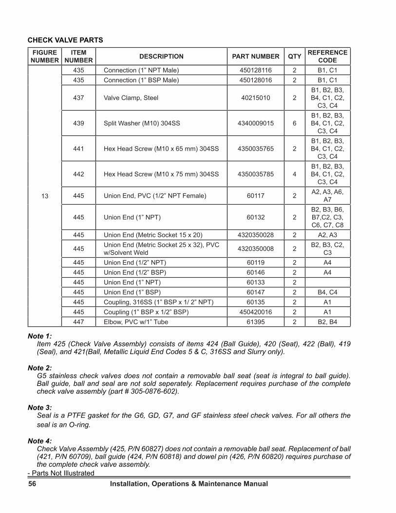
56 Installation, Operations & Maintenance Manual
CHECK VALVE PARTSFIGURE
NUMBERITEM
NUMBER DESCRIPTION PART NUMBER QTY REFERENCE CODE
13
435 Connection (1” NPT Male) 450128116 2 B1, C1435 Connection (1” BSP Male) 450128016 2 B1, C1
437 Valve Clamp, Steel 40215010 2B1, B2, B3, B4, C1, C2,
C3, C4
439 Split Washer (M10) 304SS 4340009015 6B1, B2, B3, B4, C1, C2,
C3, C4
441 Hex Head Screw (M10 x 65 mm) 304SS 4350035765 2B1, B2, B3, B4, C1, C2,
C3, C4
442 Hex Head Screw (M10 x 75 mm) 304SS 4350035785 4B1, B2, B3, B4, C1, C2,
C3, C4
445 Union End, PVC (1/2” NPT Female) 60117 2 A2, A3, A6, A7
445 Union End (1” NPT) 60132 2B2, B3, B6, B7,C2, C3, C6, C7, C8
445 Union End (Metric Socket 15 x 20) 4320350028 2 A2, A3
445 Union End (Metric Socket 25 x 32), PVC w/Solvent Weld 4320350008 2 B2, B3, C2,
C3445 Union End (1/2” NPT) 60119 2 A4445 Union End (1/2” BSP) 60146 2 A4445 Union End (1” NPT) 60133 2445 Union End (1” BSP) 60147 2 B4, C4445 Coupling, 316SS (1” BSP x 1/ 2” NPT) 60135 2 A1445 Coupling (1” BSP x 1/2” BSP) 450420016 2 A1447 Elbow, PVC w/1” Tube 61395 2 B2, B4
Note 1:Item 425 (Check Valve Assembly) consists of items 424 (Ball Guide), 420 (Seat), 422 (Ball), 419 (Seal), and 421(Ball, Metallic Liquid End Codes 5 & C, 316SS and Slurry only).
Note 2: G5 stainless check valves does not contain a removable ball seat (seat is integral to ball guide). Ball guide, ball and seal are not sold seperately. Replacement requires purchase of the complete check valve assembly (part # 305-0876-602).
Note 3:Seal is a PTFE gasket for the G6, GD, G7, and GF stainless steel check valves. For all others the seal is an O-ring.
Note 4: Check Valve Assembly (425, P/N 60827) does not contain a removable ball seat. Replacement of ball (421, P/N 60709), ball guide (424, P/N 60818) and dowel pin (426, P/N 60820) requires purchase of the complete check valve assembly.
- Parts Not Illustrated
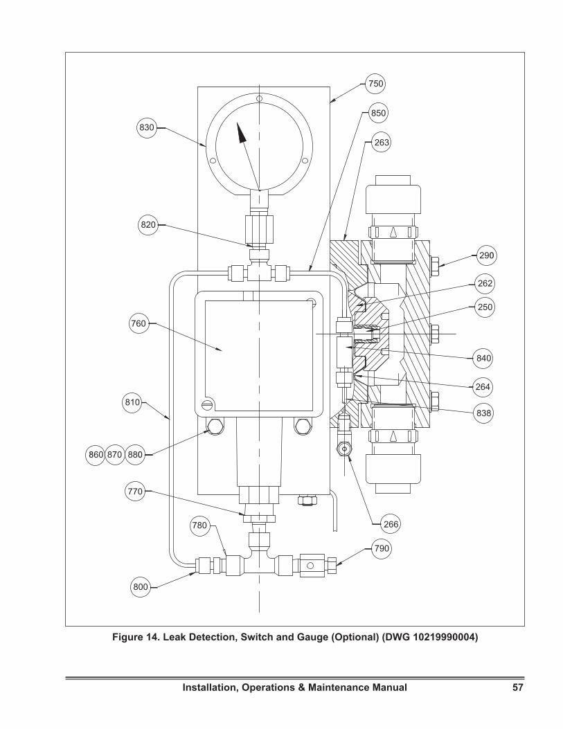
57Installation, Operations & Maintenance Manual
Figure 14. Leak Detection, Switch and Gauge (Optional) (DWG 10219990004)
750
800
770
780
810
870 880860
760
820
830
790
266
264
840
250
262
290
263
850
838
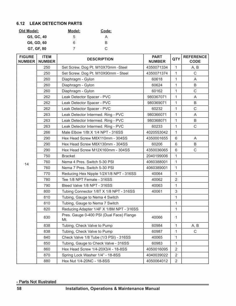
58 Installation, Operations & Maintenance Manual- Parts Not Illustrated- Parts Not Illustrated
Old Model: Model: Code:G5, GC, 40 5 AG6, GD, 60 6 BG7, GF, 80 7 C
6.12 LEAK DETECTION PARTS
FIGURE NUMBER
ITEM NUMBER DESCRIPTION PART
NUMBER QTY REFERENCE CODE
14
250 Set Screw, Dog Pt. M10X70mm -Steel 4350071334 1 A, B250 Set Screw. Dog Pt. M10X90mm - Steel 4350071374 1 C260 Diaphragm - Gylon 60618 1 A260 Diaphragm - Gylon 60624 1 B260 Diaphragm - Gylon 60162 1 C262 Leak Detector Spacer - PVC 980367071 1 A262 Leak Detector Spacer - PVC 980369071 1 B 262 Leak Detector Spacer - PVC 60232 1 C263 Leak Detector Intermed. Ring - PVC 980366071 1 A263 Leak Detector Intermed. Ring - PVC 980368071 1 B 263 Leak Detector Intermed. Ring - PVC 60233 1 C266 Male Elbow 1/8t X 1/4 NPT - 316SS 4020553042 1290 Hex Head Screw M8X110mm - 304SS 4350001655 6 A 290 Hex Head Screw M8X130mm - 304SS 60206 6 B290 Hex Head Screw M12X160mm - 304SS 4350036065 6 C750 Bracket 2040199006 1760 Nema 4 Pres. Switch 5-30 PSI 4060388001 1760 Nema 7 Pres. Switch 5-30 PSI 4060389001 1770 Reducing Hex Nipple 1/2X1/8 NPT - 316SS 40064 1780 Tee 1/8 NPT Female - 316SS 40062 2790 Bleed Valve 1/8 NPT - 316SS 40063 1800 Tubing Connector 1/8T X 1/8 NPT - 316SS 40061 3810 Tubing, Gauge to Nema 4 Switch 1810 Tubing, Gauge to Nema 7 Switch 1820 Reducing Adapter 1/4F X 1/8M NPT - 316SS 1
830 Pres. Gauge 0-400 PSI (Dual Face) Flange Mt. 40066 1
838 Tubing, Check Valve to Pump 60984 1 A, B838 Tubing, Check Valve to Pump 60987 1 C840 Check Valve 1/8 Tube (1/3 PSI) - 316SS 40065 1850 Tubing, Gauge to Check Valve - 316SS 60983 1860 Hex Head Screw 1/4-20X3/4 - 18-8SS 4050016095 2870 Spring Lock Washer 1/4” - 18-8SS 4040039022 2880 Hex Nut 1/4-20NC - 18-8SS 4050064012 2

MacRoy®® is a registered trademark of Milton Roy, LLC.© 2015 Milton Roy, LLC.
[email protected] www.miltonroy.com
We are a proud member of Accudyne Industries, a leading global provider of precision-engineered, process-critical, and technologically advanced flow control systems and industrial compressors. Delivering consistently high levels of performance, we enable customers in the most important industries and harshest environments around the worldto accomplish their missions.