Embed Size (px)
Citation preview
Macroscopic Interferometry:Rethinking Depth Estimation with Frequency-Domain Time-of-Flight
Achuta Kadambi, Jamie Schiel, and Ramesh Raskar
MIT Media Lab
{achoo,schiel,raskar}@mit.edu
Abstract
A form of meter-scale, macroscopic interferometry isproposed using conventional time-of-flight (ToF) sensors.Today, ToF sensors use phase-based sampling, where thephase delay between emitted and received, high-frequencysignals encodes distance. This paper examines an alterna-tive ToF architecture, inspired by micron-scale, microscopicinterferometry, that relies only on frequency sampling: werefer to our proposed macroscopic technique as Frequency-Domain Time of Flight (FD-ToF). The proposed architec-ture offers several benefits over existing phase ToF systems,such as robustness to phase wrapping and implicit resolu-tion of multi-path interference, all while capturing the samenumber of subframes. A prototype camera is constructed todemonstrate macroscopic interferometry at meter scale.
1. Introduction
Three-dimensional (3D) cameras capture the depth ofobjects over a spatial field. The recent emergence of low-cost, full-frame 3D cameras, such as Microsoft’s Kinect,have facilitated many new applications in diverse areasof computer vision and graphics. These advances con-tinue to drive demands for faster, more accurate, and moreinformation-rich 3D systems that can operate outside ofcontrolled environments.
Time of flight (ToF) cameras contain an active light-source that strobes coded patterns into a scene. The opticalsignal returning to the sensor exhibits a shift in phase cor-responding to the propagation distance of the signal, whichallows object depth to be calculated. This pervasive archi-tecture, used in devices such as the Microsoft Kinect andGoogle Tango, is referred to as “phase ToF”.
All phase ToF cameras rely on phase-sensing to deter-mine object depths. Accurate estimation of phase becomes
challenging in environments with, for example, multi-pathinterference. Phase is also periodic, meaning that it willwrap beyond a certain distance and create ambiguities intrue object depths. Many workarounds have been proposed,but phase ToF still remains sensitive to multi-path, wrap-ping at extreme distances, and low levels of signal-to-noise-ratio (SNR).
1.1. Contributions
Inspired by optical coherence tomography (OCT), thispaper recasts depth estimation into a macroscopic architec-ture, dubbed Frequency-Domain ToF (FD-ToF), avoidingseveral limitations with existing ToF cameras:
• Long-range objects that would ordinarily phase-wrap,can be ranged with no additional processing.
• Multi-path interference can be easily filtered with stan-dard methods, such as Fourier Transformations, with-out need for increased sampling.
• Ranging is possible in environments with extremelylow SNR.
• Drawing from existing theories in OCT, this paper pro-vides a theoretical bound for multi-path separation.
2. Related WorkThe connections between early techniques in interferom-
etry, radar, and ToF imaging are well-known. In the 1990’s,development of the modern ToF camera was inspired bythe Michelson interferometer (see [26] for a historicaloverview). However, ToF range imaging has diverged frominterferometric techniques, with little cross-pollination ofideas over the last decade. While recent work has linkedToF cameras with various radar systems [38]. In compar-ison, this paper aims to connect Frequency-Domain OCTto a complementary depth sensing architecture, Frequency-Domain ToF.
1
ObjectTCloseMirror
Detector
Mirror
Detector
ObjectTFar
CodedTStrobing
CodedTStrobing
ObjectTFar
ObjectTClose
Wavenumber
ModulationTFreq
ModulationTFreq
Wavenumber
Beamsplitter
Beamsplitter
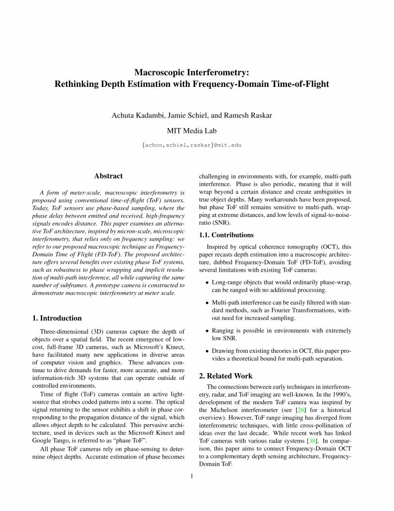
Frequency-DomainTOpticalTCoherenceTTomography Frequency-DomainTTimeTofTFlight
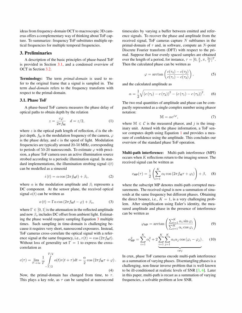
Figure 1. This paper repurposes the microscopic technique of Frequency-Domain OCT to a macroscopic technique, Frequency ToF. Bothtechniques encode optical time of flight in the frequency of the received waveform. For short optical paths (top row), the received signal inthe primal-domain is lower in frequency than that of longer optical paths (bottom row).
Multifrequency time of flight describes a class of tech-niques where a phase ToF camera repeatedly samples thescene at multiple strobing frequencies (please note the em-phasis). Our work is inspired by previous approaches inthis line that leverage the rich phase-frequency informationto recover a variety of light-transport metrics in complexscenes. Notable papers include the convex optimization al-gorithms by Heide et al. [13] and Lin et al. [25] as wellas the spectral estimation methods of Bhandari et al. [3, 4]and Freedman et al. [6]. This paper is distinguished fromprior art because it samples only in the frequency-domain,leading to a variant this paper refers to as “frequency ToF”.Since the underpinnings of frequency ToF are not new—having existed in the radar community for decades—this pa-per’s contribution lies in the empirical and theoretical eval-uation of whether frequency ToF is a beneficial architecturefor ToF cameras.
Disentangling multipath interference is one of the mostpopular topics in computational ToF imaging. The prob-lem is posed as such: in phase ToF, reflections at differentphase delays mix at a single pixel on the sensor. Extractingthe constituent phases and amplitudes is a complicated sig-nal processing problem, requiring additional measurements.We can classify prior approaches in the vein of multifre-quency phase ToF [30, 22, 13, 3, 4, 6, 31, 5] or space-timelight transport [33, 40, 41, 29, 39, 18, 10, 28, 19, 27, 21,31].1 The latter approach is complementary to this paper,as our approach is in the context of a single scene point andcould be later extended with spatial analysis. Based on theintended goals, we consider the multifrequency phase ToFapproaches of [30, 22, 3, 4] to be the closest related workand we use this as our point of comparison. If success-
1Time-coding doesn’t strictly fall into either category, but the few ex-isting works are different from our approach [20, 35].
ful, a solution to multipath interference has scope to broaderproblems, such as ultrafast imaging [37, 13, 20, 25, 15, 8, 9],scattered light imaging [36, 14], velocity imaging [12] andfluorescence imaging [2, 32, 1]. The list of references inmitigating multipath interference for ToF cameras is vast.Rather than proposing yet another specialized method, thispaper introduces frequency ToF, where multipath correctionis implicit in the Fourier Transform.
Phase wrapping is an artifact occuring in phase ToFwhere depth can only be recovered to a modulo factor.Phase unwrapping techniques address this problem by us-ing multifrequency phase ToF, where each frequency yieldsphasor measurement [22, 3]. A Lissajous pattern is formedin phasor space by tracing out phasors at multiple frequen-cies. If the Lissajous pattern does not cross over in pha-sor space, the original scene depths can be uniquely recov-ered. However, for nearby points on the Lissajous pattern,the presence of shot noise can cause the Lissajous patternto cross, leading to problems in unicity. Robust depth sens-ing at long-ranges has been achieved through the design ofboth an appropriate Lissajous pattern and incorporation ofspatial or scene priors [11]. To avoid phase wrapping alto-gether, this paper explores Frequency-Domain ToF.
Optical coherence tomography is an optical interfer-ometric technique used extensively in biomedical imag-ing [16]. Phase ToF was inspired by early, time-domainOCT systems, where the received signal is time-correlatedwith a reference signal to determine phase offset. Over thelast decade, phase ToF literature has little to do with opticalinterferometry. This paper studies the relationship betweenthe ToF camera sensor and the more recent interferometrictechnique of frequency-domain OCT. In frequency-domainOCT, 3D shape is obtained by illuminating a microscopicsample at multiple optical frequencies [7]. Transposing
ideas from frequency-domain OCT to macroscopic 3D cam-eras offers a complementary way of thinking about ToF cap-ture. To summarize: frequency ToF substitutes multiple op-tical frequencies for multiple temporal frequencies.
3. PreliminariesA description of the basic principles of phase-based ToF
is provided in Section 3.1, and a condensed overview ofOCT in Section 3.2.
Terminology: The term primal-domain is used to re-fer to the original frame that a signal is sampled in. Theterm dual-domain refers to the frequency transform withrespect to the primal-domain.
3.1. Phase ToF
A phase-based ToF camera measures the phase delay ofoptical paths to obtain depth by the relation
z =cϕ
2πfMd = z/2, (1)
where z is the optical path length of reflection, d is the ob-ject depth, fM is the modulation frequency of the camera, ϕis the phase delay, and c is the speed of light. Modulationfrequencies are typically around 20-50 MHz, correspondingto periods of 50-20 nanoseconds. To estimate ϕ with preci-sion, a phase ToF camera uses an active illumination sourcestrobed according to a periodic illumination signal. In stan-dard implementations, the illumination strobing signal i(t)can be modelled as a sinusoid
i (t) = α cos (2πfMt) + βi, (2)
where α is the modulation amplitude and βi represents aDC component. At the sensor plane, the received opticalsignal o(t) can be written as
o (t) = Γα cos (2πfMt− ϕ) + βo, (3)
where Γ ∈ [0, 1] is the attenuation in the reflected amplitudeand now βo includes DC offset from ambient light. Estimat-ing the phase would require sampling Equation 3 multipletimes. Such sampling in time-domain is challenging be-cause it requires very short, nanosecond exposures. Instead,ToF cameras cross-correlate the optical signal with a refer-ence signal at the same frequency, i.e., r(t) = cos (2πfMt).Without loss of generality set Γ = 1 to express the cross-correlation as
c(τ) = limT→∞
1
T
T/2∫−T/2
o(t)r(t+ τ)dt =α
2cos (2πfMτ + ϕ) .
(4)Now, the primal-domain has changed from time, to τ .This plays a key role, as τ can be sampled at nanosecond
timescales by varying a buffer between emitted and refer-ence signals. To recover the phase and amplitude from thereceived signal, ToF cameras capture N subframes in theprimal-domain of τ and, in software, compute an N -pointDiscrete Fourier transform (DFT) with respect to the pri-mal. Suppose that four evenly spaced samples are obtainedover the length of a period, for instance, τ = [0, π2 , π,
3π2 ]T .
Then the calculated phase can be written as
ϕ = arctan
(c(τ4)− c(τ2)
c(τ1)− c(τ3)
), (5)
and the calculated amplitude as
α =1
2
√(c (τ4)− c (τ2))
2 − (c (τ1)− c (τ3))2. (6)
The two real quantities of amplitude and phase can be com-pactly represented as a single complex number using phasornotation:
M = αejϕ, (7)
where M ∈ C is the measured phasor, and j is the imag-inary unit. Armed with the phase information, a ToF sen-sor computes depth using Equation 1 and provides a mea-sure of confidence using the amplitude. This concludes ouroverview of the standard phase ToF operation.
Multi-path interference: Multi-path interference (MPI)occurs whenK reflections return to the imaging sensor. Thereceived signal can be written as
cMP(τ) =1
2
(K∑l=1
αl cos (2πfMτ + ϕl)
)+ β, (8)
where the subscript MP denotes multi-path corrupted mea-surements. The received signal is now a summation of sinu-soids at the same frequency but different phases. Obtainingthe direct bounce, i.e., K = 1, is a very challenging prob-lem. After simplification using Euler’s identity, the mea-sured amplitude and phase in the presence of interferencecan be written as
ϕMP = arctan
(∑Ki=1 αi sinϕi∑Ki=1 αi cosϕi
)(9)
α2MP =
K∑i=1
α2i + 2
K∑i=1
K∑j=1
αiαj cos (ϕi − ϕj)︸ ︷︷ ︸i 6=j
. (10)
In crux, phase ToF cameras encode multi-path interferenceas a summation of varying phases. Disentangling phases is achallenging, non-linear inverse problem that is well-knownto be ill-conditioned at realistic levels of SNR [3, 6]. Laterin this paper, multi-path is recast as a summation of varyingfrequencies, a solvable problem at low SNR.
Increasing the modulation frequency: Increasing themodulation frequency of phase ToF allows for greater depthprecision [24]. Intuitively, at high frequencies, a smallchange in the estimated phase, corresponds to a smallchange in the estimated depth. The range accuracy ∆L isproportional to
∆L ∝ c/fM. (11)
Over the past few years, phase ToF hardware has supportedincreased modulation frequencies to boost depth precision.For instance, the new Kinect tripled the modulation fre-quency, increasing the modulation frequency to about 100MHz. However, this frequency is at the upper limit of whatthe phase ToF architecture can handle. Without using phaseunwrapping, scene objects at a depth greater than
dambiguity = c/2fM, (12)
will encounter wrapping. Unwrapping, or disambiguationof phase, requires more measurements in combinationwith a lookup table and is susceptible to noise [23].Another challenge at high modulation frequencies is anincrease in the required sampling rate in the primal-domain.Frequency-Domain ToF does not have such drawbackswhen using high strobing frequencies.
3.2. Primer on optical coherence tomographyOptical coherence tomography performs correlation di-
rectly on the optical signal using either: Time-Domain OCT(TD-OCT) to time-correlate an optical reference with asample or Frequency-Domain OCT (FD-OCT) to sampleonly in frequency domain.2 In this section, we provide aconcise overview of FD-OCT, describing only the facetsthat can be applied to 3D cameras.
FD-OCT obtains depth by sampling the signal at dif-ferent optical wavelengths (i.e. wavelength is the primal-domain). Figure 1 provides a schematic for the typical FD-OCT system. At a single wavelength, the detector receivesan electric field from the reference object, which takes theform of
R (λ) = α(λ)ejϕR(λ), (13)
where R(λ) represents the received phasor as a functionof optical wavelength. Similarly, the received electric fieldfrom the sample object is written as
S (λ) = α(λ)ejϕS(λ). (14)
Note that the amplitude of the sample and reference are as-sumed to be equal, which simplifies our explanation of theconcept. A combination of the two reflections return to animaging sensor. The electric field at the detector is the sum-mation
M (λ) =1
2(R (λ) + S (λ)) , (15)
2Phase ToF was inspired by TD-OCT [26].
where it is assumed that the constituent phasors are halvedwhen they recombine (for instance, due to a beamsplitter).The current measured at the detector can be expressed asthe real quantity
i (λ) =ηq
hν|M (λ)|2 , (16)
where η is the detector sensitivity, q is the quantum of elec-tric charge, h is Planck’s constant, and ν is the optical fre-quency. By substituting Equation 15 into 16 we obtain
i (λ) = 14ηqhν
R (λ) (R (λ))∗
+ S (λ) (S (λ))∗︸ ︷︷ ︸
Autocorrelation
+ 2Re((R (λ))
∗ S (λ) e−jϕz)︸ ︷︷ ︸
Crosscorrelation
.
(17)Here, ϕz represents the phase delay due to the differencein optical path length between the reference and optical re-flections. Similar to the ToF case, phase and z-distance arerelated:
ϕz = 2πz/λ. (18)
In Equation 17 note that the Autocorrelation terms are DCwith respect to the wavelength. By using this relation alongwith Equation 18, Equation 17 is rewritten as
i (λ) =1
2
ηq
hν(α (λ))
2
(1 + 2 cos
(2πz
λ
)). (19)
Now we introduce an auxiliary variable k = 2π/λ, whichis known as the wave number. Equation 19 can be rewrittenas
i (k) =1
2
ηq
hν(α (k))
2(1 + 2 cos (kz)) , (20)
where now the primal-domain is the wavenumber (k). Thedual can be computed as
F [i (k)] (κ) ∝ δ (κ) + δ (κ± z) , (21)
where κ represents the dual domain. To summarize: inFrequency-Domain OCT, reflections at multiple wavenum-bers are measured at the detector and depth is encoded inthe frequency of the received signal in primal-domain.
4. Frequency-Domain Time-of-FlightInspired by Frequency-Domain OCT, the conventional
operation of ToF cameras is re-examined. In this sectiona recipe for depth estimation is provided by sampling dif-ferent modulation frequencies at a single phase step. Thisarchitecture is the proposed Frequency-Domain ToF, wherethe primal-domain is modulation frequency.
4.1. Depth sensing using only modulation frequencyDepth is calculated, not from phase steps, but from fre-
quency steps. Recall from Section 3.1 that the received sig-nal takes the form of
c(τ) =α
2cos (2πfMτ + ϕ) + β. (22)
0 0.5 1 1.5 2 2.5 3
Modulation Frequency (Hertz) x 107
-4
-2
0
2
4
Inte
nsity
(ph
oton
s)
x 104 Fixed Phase, Swept Frequency
object at 10 metersobject at 20 meters
0 5 10 15 20 25 30
Depth (meters)
0
1
2
3
Inte
nsity
(ph
oton
s)
x 104 Fourier Spectrum
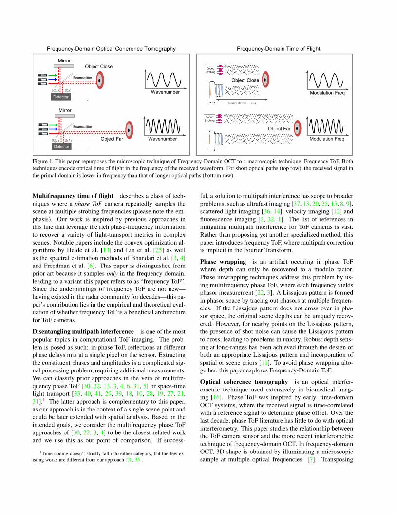
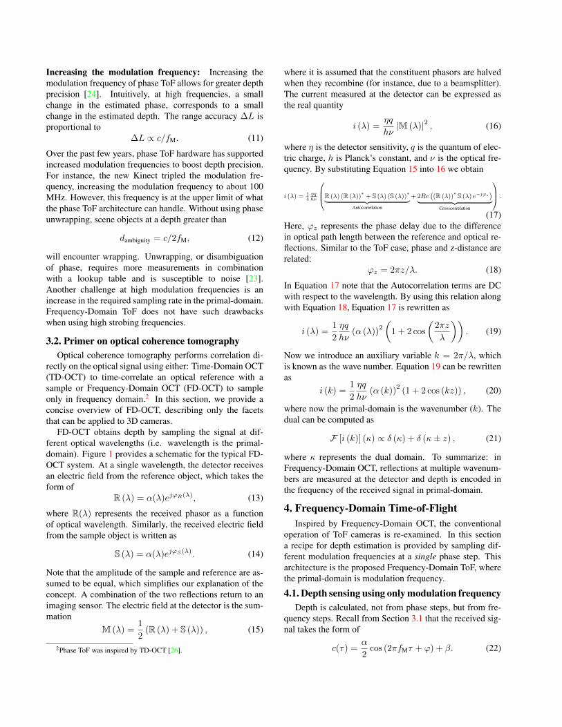
Figure 2. Multi-path interference is inherently resolved in Frequency-Domain ToF. (left) Multi-path interference from two reflections causethe measured signal (black) to have two tones (right). This simulation uses a frequency bandwidth of 1Ghz (left plot windowed for clarity).
In standard phase ToF, τ represents the primal-domainagainst which one would ordinarily compute the N -pointDFT. Instead, consider substituting Equation 1 into Equa-tion 4 to obtain
c(τ, fM) =α
2cos
(2πfMτ +
2πz
cfM
)+ β. (23)
Without loss of generality assume that this signal is sampledonly at the zero shift, i.e., τ = 0. Then the received signalat the sensor takes the form of
c(τ = 0, fM) = c(fM) =α
2cos
(2πz
cfM
)+ β. (24)
Now the primal domain is fM and the associated dual takesthe form of
F [c (fM)] (κ) ∝ δ (κ) + δ
(κ± 2πz
c
), (25)
where κ is the dual-domain, corresponding to the inverse ofthe modulation frequency. Analogous to FD-OCT the depthcan be obtained by finding the location of the support in thedual domain.
4.2. Multi-path interference in FD-ToFAn advantage of Frequency-Domain ToF is that multi-
path interference is separable in the dual-domain. Recallthat in the multi-path problem, K reflections return to thesensor and the received signal is given by
c(fM) =1
2
(K∑l=1
αl cos
(2πzlcfM
))+ β. (26)
The associated Fourier transform may now be written as
F [c (fM)] (κ) ∝ δ (κ) +
K∑l=1
αlδ
(κ± 2πzl
c
). (27)
Here, the multi-path corrupted signal is a sum of sinusoidsat the same phase but at different frequencies. As shownin Figure 2, a Fourier transform allows resolution of multi-path interference.
4.3. Estimating frequency to obtain depthFrequency-Domain ToF recasts depth estimation into
the problem of frequency estimation of the received sig-nal (Equation 27). The number of subframes required fordepth estimation is the same as for phase ToF (since bothrely on sinusoidal sampling). To estimate multi-path, thesampling rate must obey the Nyquist rate; therefore, no lessthan 2K samples can be taken to resolve K multi-path re-flections. In theory, FD-ToF is susceptible to long-range ar-tifacts because very large depths can alias to lower frequen-cies. This is avoided by appropriately choosing the sam-pling rate (for example, adhering to the Nyquist rate of thehighest-frequency component, if it is known) in the primal-domain. The reader is directed to the supplement and Stoicaet al. [34] for details about frequency estimation.
4.4. Frequency bandwidth and resolutionBy casting the problem in the realm of OCT, recovery
bounds can be provided for multi-path interference. Previ-ous work in ToF literature [13, 20, 25] has not consideredto what resolution multi-path reflections can be separated.The duality between OCT and Frequency-Domain ToF re-veals the following:Proposition 1: Multi-path interference can be resolved inFrequency-Domain ToF if the optical path-length betweenany two reflections is less than:
∆z ≈ 0.6c/∆fM. (28)
Proof (Sketch): The sampling function in the primal do-main is a boxcar function Π (fM) = H
(fM − f−M
)−
H(fM − f+
M
), where f−M and f+
M represent the minimumand maximum modulation frequencies that are sampled andH(·) refers to the Heaviside step function. The Fouriertransform of Π (fM) takes the form of a scaled sinc functionF [Π (fM)] (κ) ∝ ∆fM
sin ∆fMκ∆fMκ
, where ∆fM = f+M − f
−M .
The FWHM of this function determines the axial resolution∆z. After simplification (see supplement), this can be ap-proximated as ∆z ≈ 0.6c/∆fM, the desired result.�
Not surprisingly, a larger frequency bandwidth ∆fM im-proves the optical path resolution.
50 200 350 500 650 8000
1
2
3
4
Min
Mul
tipat
h S
ep. (
m) Axial Resolution: Theoretical vs Observed
Theoretical BoundShot Noise Experiment
Frequency Bandwidth (MHz)
1000
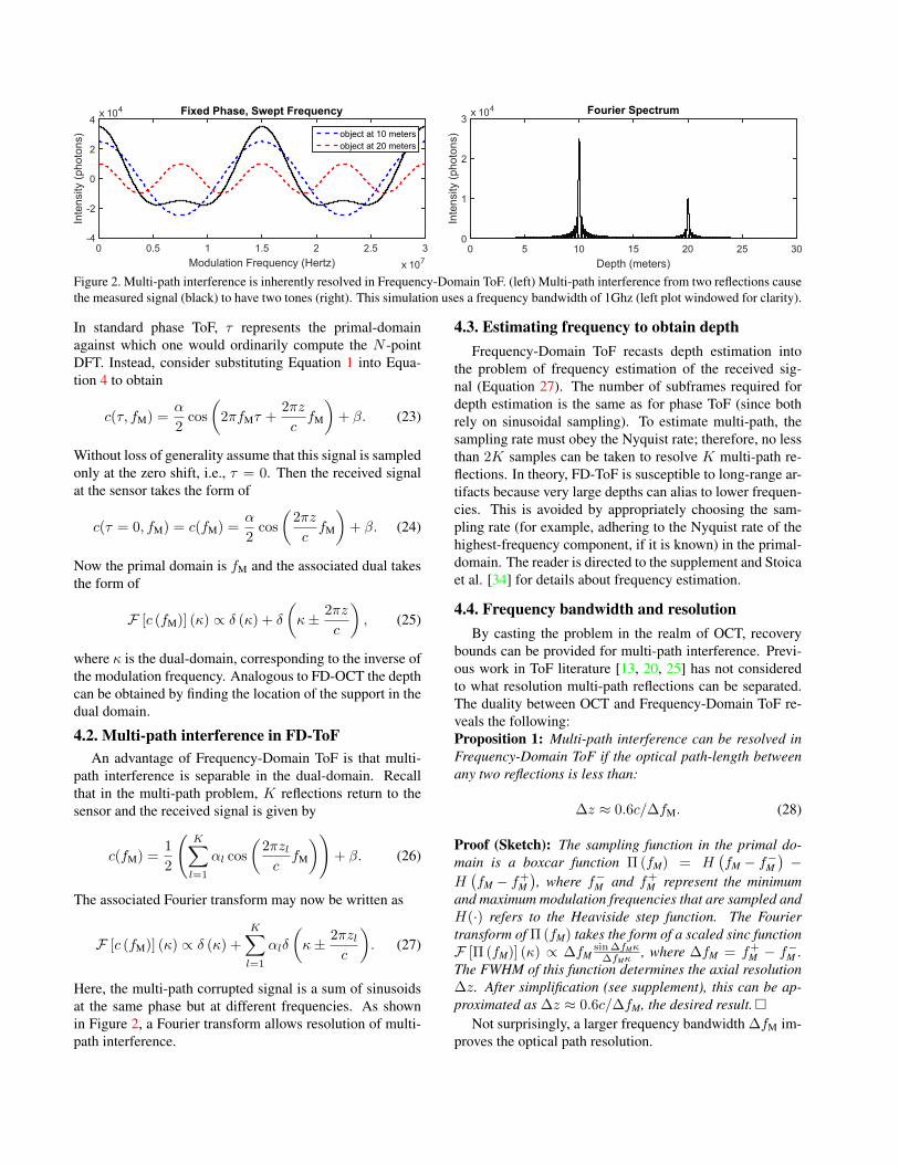
Figure 3. We show that the noiseless bound derived in Proposition1 is valid in typical shot noise limited scenarios.
5. Assessment and ResultsWithout any additions to hardware beyond the typical
components of a ToF camera, and using fewer capturedimages, the proposed technique is shown to handle chal-lenging scenes with multi-path interference, large distances,and low SNR. Comparisons were performed to a state-of-the-art paper that uses both multiple frequencies and phasesteps to mitigate multi-path interference (hereafter Bhan-dari’s method) [3].
5.1. Synthetic scenesResolution bound: Proposition 1 describes an upperbound on multi-path resolution, derived in the main paperfor the noiseless case. This bound is based on the samplingproperties of the system (i.e. highest and lowest frequen-cies sampled) and does not factor noise. However, Figure3 shows that at SNRs, governed by shot-noise, of a typicalcamera, the observed resolution very nearly approaches thebest-case resolution bound. To our knowledge, this is one ofonly a few papers in ToF imaging to analyze the minimumseparation needed to accurately resolve multi-path. Thesupplement contains a derivation of the resolution bound.
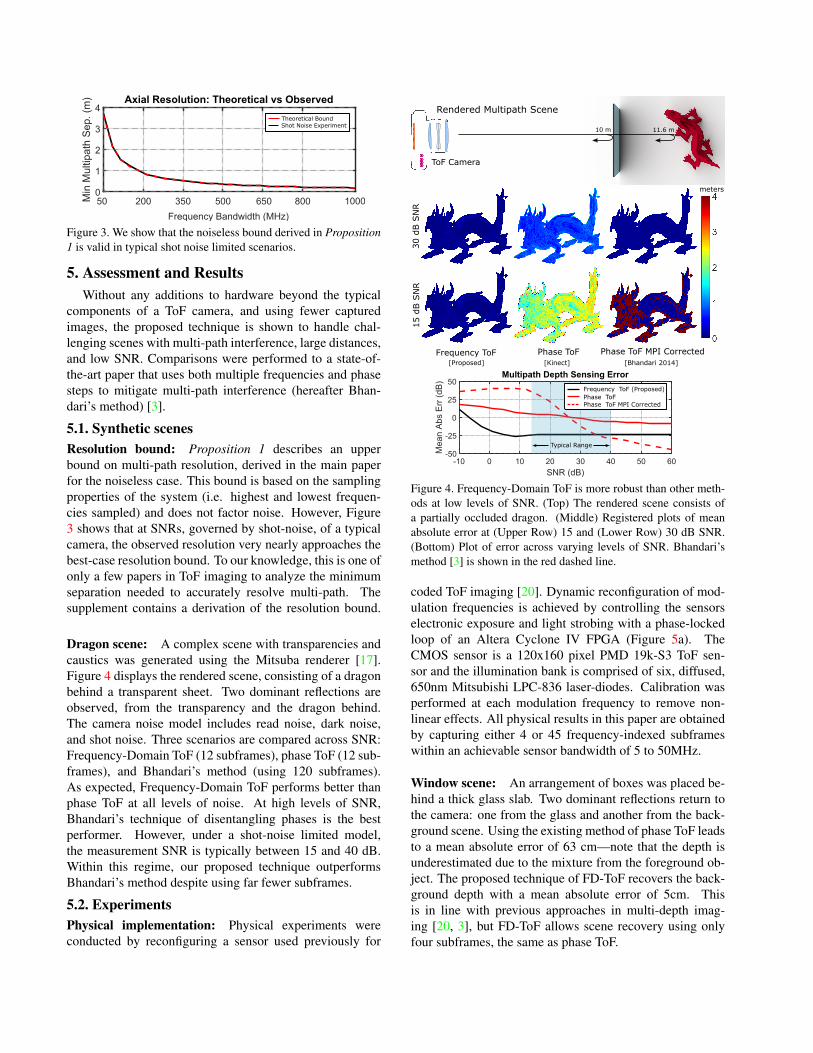
Dragon scene: A complex scene with transparencies andcaustics was generated using the Mitsuba renderer [17].Figure 4 displays the rendered scene, consisting of a dragonbehind a transparent sheet. Two dominant reflections areobserved, from the transparency and the dragon behind.The camera noise model includes read noise, dark noise,and shot noise. Three scenarios are compared across SNR:Frequency-Domain ToF (12 subframes), phase ToF (12 sub-frames), and Bhandari’s method (using 120 subframes).As expected, Frequency-Domain ToF performs better thanphase ToF at all levels of noise. At high levels of SNR,Bhandari’s technique of disentangling phases is the bestperformer. However, under a shot-noise limited model,the measurement SNR is typically between 15 and 40 dB.Within this regime, our proposed technique outperformsBhandari’s method despite using far fewer subframes.
5.2. ExperimentsPhysical implementation: Physical experiments wereconducted by reconfiguring a sensor used previously for
ToF Camera
Rendered Multipath Scene
15 d
B S
NR
Phase ToF Phase ToF MPI Corrected
30 d
B S
NR
Frequency ToF[Bhandari 2014]
-10 0 10 20 30 40 50 60
SNR (dB)
-50
-25
0
25
50
Mea
n A
bs E
rr (
dB)
Multipath Depth Sensing Error
Frequency ToF (Proposed)Phase ToFPhase ToF MPI Corrected
Typical Range
meters
10 m 11.6 m
[Proposed] [Kinect]
Figure 4. Frequency-Domain ToF is more robust than other meth-ods at low levels of SNR. (Top) The rendered scene consists ofa partially occluded dragon. (Middle) Registered plots of meanabsolute error at (Upper Row) 15 and (Lower Row) 30 dB SNR.(Bottom) Plot of error across varying levels of SNR. Bhandari’smethod [3] is shown in the red dashed line.
coded ToF imaging [20]. Dynamic reconfiguration of mod-ulation frequencies is achieved by controlling the sensorselectronic exposure and light strobing with a phase-lockedloop of an Altera Cyclone IV FPGA (Figure 5a). TheCMOS sensor is a 120x160 pixel PMD 19k-S3 ToF sen-sor and the illumination bank is comprised of six, diffused,650nm Mitsubishi LPC-836 laser-diodes. Calibration wasperformed at each modulation frequency to remove non-linear effects. All physical results in this paper are obtainedby capturing either 4 or 45 frequency-indexed subframeswithin an achievable sensor bandwidth of 5 to 50MHz.
Window scene: An arrangement of boxes was placed be-hind a thick glass slab. Two dominant reflections return tothe camera: one from the glass and another from the back-ground scene. Using the existing method of phase ToF leadsto a mean absolute error of 63 cm—note that the depth isunderestimated due to the mixture from the foreground ob-ject. The proposed technique of FD-ToF recovers the back-ground depth with a mean absolute error of 5cm. Thisis in line with previous approaches in multi-depth imag-ing [20, 3], but FD-ToF allows scene recovery using onlyfour subframes, the same as phase ToF.
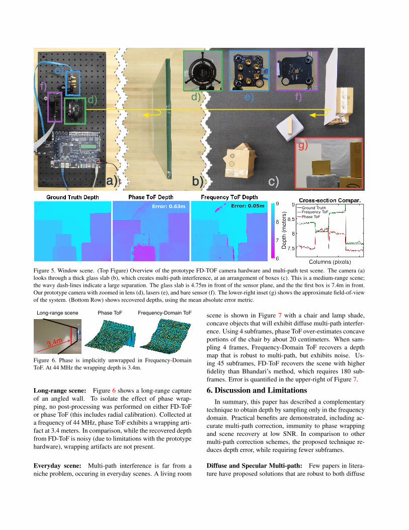
Ground TruthFrequency ToFPhase ToF
Error: 0.05mError: 0.63m
Figure 5. Window scene. (Top Figure) Overview of the prototype FD-TOF camera hardware and multi-path test scene. The camera (a)looks through a thick glass slab (b), which creates multi-path interference, at an arrangement of boxes (c). This is a medium-range scene;the wavy dash-lines indicate a large separation. The glass slab is 4.75m in front of the sensor plane, and the the first box is 7.4m in front.Our prototype camera with zoomed in lens (d), lasers (e), and bare sensor (f). The lower-right inset (g) shows the approximate field-of-viewof the system. (Bottom Row) shows recovered depths, using the mean absolute error metric.
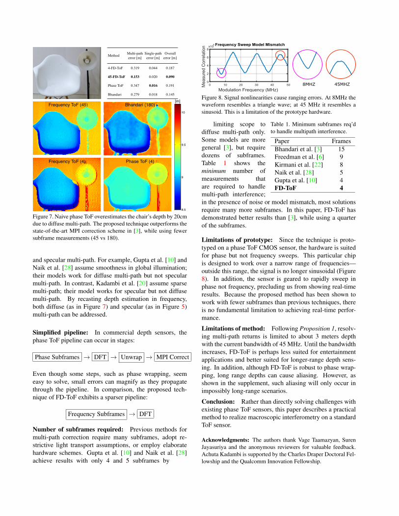
Phase ToF Frequency-Domain ToFLong-range scene
3.4m
Figure 6. Phase is implicitly unwrapped in Frequency-DomainToF. At 44 MHz the wrapping depth is 3.4m.
Long-range scene: Figure 6 shows a long-range captureof an angled wall. To isolate the effect of phase wrap-ping, no post-processing was performed on either FD-ToFor phase ToF (this includes radial calibration). Collected ata frequency of 44 MHz, phase ToF exhibits a wrapping arti-fact at 3.4 meters. In comparison, while the recovered depthfrom FD-ToF is noisy (due to limitations with the prototypehardware), wrapping artifacts are not present.
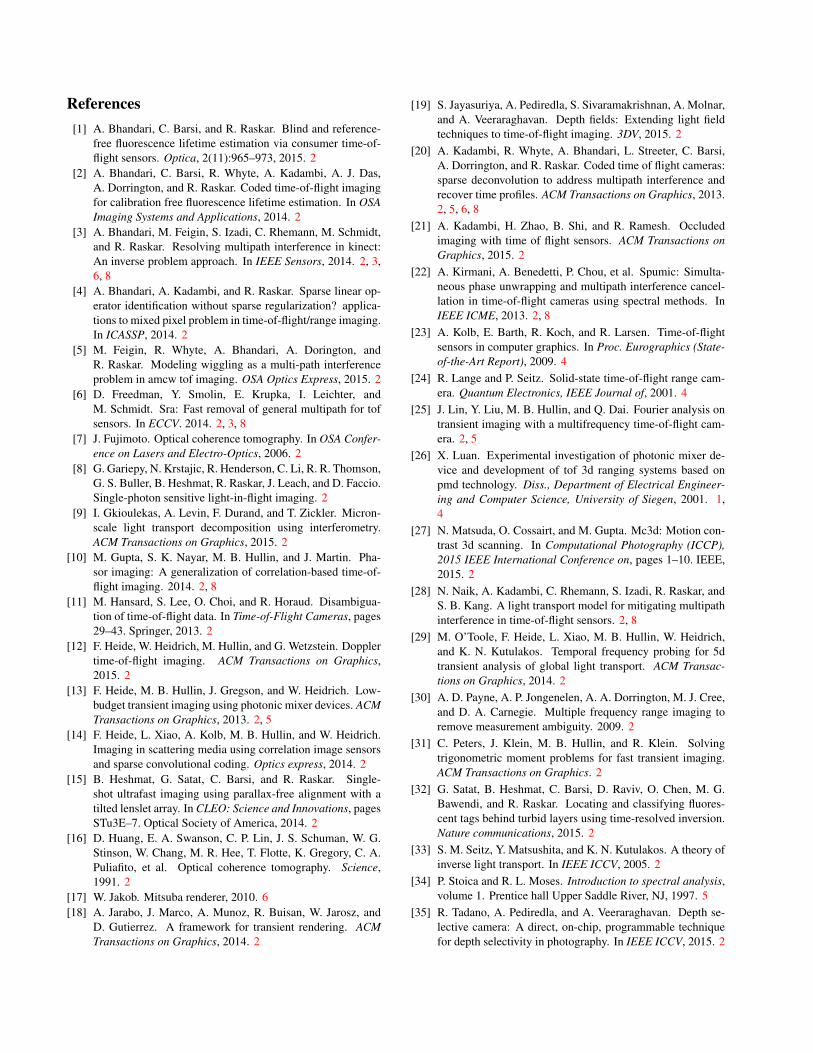
Everyday scene: Multi-path interference is far from aniche problem, occuring in everyday scenes. A living room
scene is shown in Figure 7 with a chair and lamp shade,concave objects that will exhibit diffuse multi-path interfer-ence. Using 4 subframes, phase ToF over-estimates concaveportions of the chair by about 20 centimeters. When sam-pling 4 frames, Frequency-Domain ToF recovers a depthmap that is robust to multi-path, but exhibits noise. Us-ing 45 subframes, FD-ToF recovers the scene with higherfidelity than Bhandari’s method, which requires 180 sub-frames. Error is quantified in the upper-right of Figure 7.
6. Discussion and LimitationsIn summary, this paper has described a complementary
technique to obtain depth by sampling only in the frequencydomain. Practical benefits are demonstrated, including ac-curate multi-path correction, immunity to phase wrappingand scene recovery at low SNR. In comparison to othermulti-path correction schemes, the proposed technique re-duces depth error, while requiring fewer subframes.
Diffuse and Specular Multi-path: Few papers in litera-ture have proposed solutions that are robust to both diffuse
20 40 60 80 100 120 140 160
20
40
60
80
100
120 8.5
9
9.5
10
Frequency ToF (4) Phase ToF (4)
Frequency ToF (45) Bhandari (180)[m]
MethodMulti-path
error [m]
Single-path
error [m]
Overall
error [m]
4-FD-ToF 0.319 0.044 0.187
45-FD-ToF 0.153 0.020 0.090
Phase ToF 0.347 0.016 0.191
Bhandari 0.279 0.018 0.145
Figure 7. Naive phase ToF overestimates the chair’s depth by 20cmdue to diffuse multi-path. The proposed technique outperforms thestate-of-the-art MPI correction scheme in [3], while using fewersubframe measurements (45 vs 180).
and specular multi-path. For example, Gupta et al. [10] andNaik et al. [28] assume smoothness in global illumination;their models work for diffuse multi-path but not specularmulti-path. In contrast, Kadambi et al. [20] assume sparsemulti-path; their model works for specular but not diffusemulti-path. By recasting depth estimation in frequency,both diffuse (as in Figure 7) and specular (as in Figure 5)multi-path can be addressed.
Simplified pipeline: In commercial depth sensors, thephase ToF pipeline can occur in stages:
Phase Subframes → DFT → Unwrap → MPI Correct
Even though some steps, such as phase wrapping, seemeasy to solve, small errors can magnify as they propagatethrough the pipeline. In comparison, the proposed tech-nique of FD-ToF exhibits a sparser pipeline:
Frequency Subframes → DFT
Number of subframes required: Previous methods formulti-path correction require many subframes, adopt re-strictive light transport assumptions, or employ elaboratehardware schemes. Gupta et al. [10] and Naik et al. [28]achieve results with only 4 and 5 subframes by
0 10 20 30 40 50
Modulation Frequency (MHz)
0
2
4
6
8
Mea
sure
d C
orre
latio
n x104 Frequency Sweep Model Mismatch
45MHZ8MHZ
Figure 8. Signal nonlinearities cause ranging errors. At 8MHz thewaveform resembles a triangle wave; at 45 MHz it resembles asinusoid. This is a limitation of the prototype hardware.
Table 1. Minimum subframes req’dto handle multipath interference.
Paper FramesBhandari et al. [3] 15Freedman et al. [6] 9Kirmani et al. [22] 8Naik et al. [28] 5Gupta et al. [10] 4FD-ToF 4
limiting scope todiffuse multi-path only.Some models are moregeneral [3], but requiredozens of subframes.Table 1 shows theminimum number ofmeasurements thatare required to handlemulti-path interference;in the presence of noise or model mismatch, most solutionsrequire many more subframes. In this paper, FD-ToF hasdemonstrated better results than [3], while using a quarterof the subframes.
Limitations of prototype: Since the technique is proto-typed on a phase ToF CMOS sensor, the hardware is suitedfor phase but not frequency sweeps. This particular chipis designed to work over a narrow range of frequencies—outside this range, the signal is no longer sinusoidal (Figure8). In addition, the sensor is geared to rapidly sweep inphase not frequency, precluding us from showing real-timeresults. Because the proposed method has been shown towork with fewer subframes than previous techniques, thereis no fundamental limitation to achieving real-time perfor-mance.
Limitations of method: Following Proposition 1, resolv-ing multi-path returns is limited to about 3 meters depthwith the current bandwidth of 45 MHz. Until the bandwidthincreases, FD-ToF is perhaps less suited for entertainmentapplications and better suited for longer-range depth sens-ing. In addition, although FD-ToF is robust to phase wrap-ping, long range depths can cause aliasing. However, asshown in the supplement, such aliasing will only occur inimpossibly long-range scenarios.
Conclusion: Rather than directly solving challenges withexisting phase ToF sensors, this paper describes a practicalmethod to realize macroscopic interferometry on a standardToF sensor.
Acknowledgments: The authors thank Vage Taamazyan, SurenJayasuriya and the anonymous reviewers for valuable feedback.Achuta Kadambi is supported by the Charles Draper Doctoral Fel-lowship and the Qualcomm Innovation Fellowship.
References[1] A. Bhandari, C. Barsi, and R. Raskar. Blind and reference-
free fluorescence lifetime estimation via consumer time-of-flight sensors. Optica, 2(11):965–973, 2015. 2
[2] A. Bhandari, C. Barsi, R. Whyte, A. Kadambi, A. J. Das,A. Dorrington, and R. Raskar. Coded time-of-flight imagingfor calibration free fluorescence lifetime estimation. In OSAImaging Systems and Applications, 2014. 2
[3] A. Bhandari, M. Feigin, S. Izadi, C. Rhemann, M. Schmidt,and R. Raskar. Resolving multipath interference in kinect:An inverse problem approach. In IEEE Sensors, 2014. 2, 3,6, 8
[4] A. Bhandari, A. Kadambi, and R. Raskar. Sparse linear op-erator identification without sparse regularization? applica-tions to mixed pixel problem in time-of-flight/range imaging.In ICASSP, 2014. 2
[5] M. Feigin, R. Whyte, A. Bhandari, A. Dorington, andR. Raskar. Modeling wiggling as a multi-path interferenceproblem in amcw tof imaging. OSA Optics Express, 2015. 2
[6] D. Freedman, Y. Smolin, E. Krupka, I. Leichter, andM. Schmidt. Sra: Fast removal of general multipath for tofsensors. In ECCV. 2014. 2, 3, 8
[7] J. Fujimoto. Optical coherence tomography. In OSA Confer-ence on Lasers and Electro-Optics, 2006. 2
[8] G. Gariepy, N. Krstajic, R. Henderson, C. Li, R. R. Thomson,G. S. Buller, B. Heshmat, R. Raskar, J. Leach, and D. Faccio.Single-photon sensitive light-in-flight imaging. 2
[9] I. Gkioulekas, A. Levin, F. Durand, and T. Zickler. Micron-scale light transport decomposition using interferometry.ACM Transactions on Graphics, 2015. 2
[10] M. Gupta, S. K. Nayar, M. B. Hullin, and J. Martin. Pha-sor imaging: A generalization of correlation-based time-of-flight imaging. 2014. 2, 8
[11] M. Hansard, S. Lee, O. Choi, and R. Horaud. Disambigua-tion of time-of-flight data. In Time-of-Flight Cameras, pages29–43. Springer, 2013. 2
[12] F. Heide, W. Heidrich, M. Hullin, and G. Wetzstein. Dopplertime-of-flight imaging. ACM Transactions on Graphics,2015. 2
[13] F. Heide, M. B. Hullin, J. Gregson, and W. Heidrich. Low-budget transient imaging using photonic mixer devices. ACMTransactions on Graphics, 2013. 2, 5
[14] F. Heide, L. Xiao, A. Kolb, M. B. Hullin, and W. Heidrich.Imaging in scattering media using correlation image sensorsand sparse convolutional coding. Optics express, 2014. 2
[15] B. Heshmat, G. Satat, C. Barsi, and R. Raskar. Single-shot ultrafast imaging using parallax-free alignment with atilted lenslet array. In CLEO: Science and Innovations, pagesSTu3E–7. Optical Society of America, 2014. 2
[16] D. Huang, E. A. Swanson, C. P. Lin, J. S. Schuman, W. G.Stinson, W. Chang, M. R. Hee, T. Flotte, K. Gregory, C. A.Puliafito, et al. Optical coherence tomography. Science,1991. 2
[17] W. Jakob. Mitsuba renderer, 2010. 6[18] A. Jarabo, J. Marco, A. Munoz, R. Buisan, W. Jarosz, and
D. Gutierrez. A framework for transient rendering. ACMTransactions on Graphics, 2014. 2
[19] S. Jayasuriya, A. Pediredla, S. Sivaramakrishnan, A. Molnar,and A. Veeraraghavan. Depth fields: Extending light fieldtechniques to time-of-flight imaging. 3DV, 2015. 2
[20] A. Kadambi, R. Whyte, A. Bhandari, L. Streeter, C. Barsi,A. Dorrington, and R. Raskar. Coded time of flight cameras:sparse deconvolution to address multipath interference andrecover time profiles. ACM Transactions on Graphics, 2013.2, 5, 6, 8
[21] A. Kadambi, H. Zhao, B. Shi, and R. Ramesh. Occludedimaging with time of flight sensors. ACM Transactions onGraphics, 2015. 2
[22] A. Kirmani, A. Benedetti, P. Chou, et al. Spumic: Simulta-neous phase unwrapping and multipath interference cancel-lation in time-of-flight cameras using spectral methods. InIEEE ICME, 2013. 2, 8
[23] A. Kolb, E. Barth, R. Koch, and R. Larsen. Time-of-flightsensors in computer graphics. In Proc. Eurographics (State-of-the-Art Report), 2009. 4
[24] R. Lange and P. Seitz. Solid-state time-of-flight range cam-era. Quantum Electronics, IEEE Journal of, 2001. 4
[25] J. Lin, Y. Liu, M. B. Hullin, and Q. Dai. Fourier analysis ontransient imaging with a multifrequency time-of-flight cam-era. 2, 5
[26] X. Luan. Experimental investigation of photonic mixer de-vice and development of tof 3d ranging systems based onpmd technology. Diss., Department of Electrical Engineer-ing and Computer Science, University of Siegen, 2001. 1,4
[27] N. Matsuda, O. Cossairt, and M. Gupta. Mc3d: Motion con-trast 3d scanning. In Computational Photography (ICCP),2015 IEEE International Conference on, pages 1–10. IEEE,2015. 2
[28] N. Naik, A. Kadambi, C. Rhemann, S. Izadi, R. Raskar, andS. B. Kang. A light transport model for mitigating multipathinterference in time-of-flight sensors. 2, 8
[29] M. O’Toole, F. Heide, L. Xiao, M. B. Hullin, W. Heidrich,and K. N. Kutulakos. Temporal frequency probing for 5dtransient analysis of global light transport. ACM Transac-tions on Graphics, 2014. 2
[30] A. D. Payne, A. P. Jongenelen, A. A. Dorrington, M. J. Cree,and D. A. Carnegie. Multiple frequency range imaging toremove measurement ambiguity. 2009. 2
[31] C. Peters, J. Klein, M. B. Hullin, and R. Klein. Solvingtrigonometric moment problems for fast transient imaging.ACM Transactions on Graphics. 2
[32] G. Satat, B. Heshmat, C. Barsi, D. Raviv, O. Chen, M. G.Bawendi, and R. Raskar. Locating and classifying fluores-cent tags behind turbid layers using time-resolved inversion.Nature communications, 2015. 2
[33] S. M. Seitz, Y. Matsushita, and K. N. Kutulakos. A theory ofinverse light transport. In IEEE ICCV, 2005. 2
[34] P. Stoica and R. L. Moses. Introduction to spectral analysis,volume 1. Prentice hall Upper Saddle River, NJ, 1997. 5
[35] R. Tadano, A. Pediredla, and A. Veeraraghavan. Depth se-lective camera: A direct, on-chip, programmable techniquefor depth selectivity in photography. In IEEE ICCV, 2015. 2
[36] A. Velten, T. Willwacher, O. Gupta, A. Veeraraghavan, M. G.Bawendi, and R. Raskar. Recovering three-dimensionalshape around a corner using ultrafast time-of-flight imaging.Nature Communications, 2012. 2
[37] A. Velten, D. Wu, A. Jarabo, B. Masia, C. Barsi, C. Joshi,E. Lawson, M. Bawendi, D. Gutierrez, and R. Raskar.Femto-photography: Capturing and visualizing the propaga-tion of light. ACM Transactions on Graphics, 2013. 2
[38] R. Whyte, L. Streeter, M. Cree, and A. Dorrington. Applica-tion of lidar techniques to time-of-flight range imaging. Ap-plied Optics, 2015 (To Appear). 1
[39] R. Whyte, L. Streeter, M. J. Cree, and A. A. Dorrington.Resolving multiple propagation paths in time of flight rangecameras using direct and global separation methods. OpticalEngineering, 54(11):113109–113109, 2015. 2
[40] D. Wu, A. Velten, M. OToole, B. Masia, A. Agrawal, Q. Dai,and R. Raskar. Decomposing global light transport usingtime of flight imaging. International Journal of ComputerVision, 2014. 2
[41] D. Wu, G. Wetzstein, C. Barsi, T. Willwacher, Q. Dai, andR. Raskar. Ultra-fast lensless computational imaging through5d frequency analysis of time-resolved light transport. Inter-national Journal of Computer Vision, 110(2):128–140, 2014.2