Embed Size (px)
Citation preview

Film-Tech
The information contained in this Adobe Acrobat pdf file is provided at your own risk and good judgment.
These manuals are designed to facilitate the exchange of information related to cinema
projection and film handling, with no warranties nor obligations from the authors, for qualified field
service engineers.
If you are not a qualified technician, please make no adjuatments to anything you may read about in these
Adobe manual downloads
www.film-tech.com

1
AUXU
1
2
3
4
5
6
U
U
U
+1500
+1500
+1500
+15005/6
SHIFT
+15–15
0HI
+15–15
0MID
+12–120
LO
EQ0
RLPAN
SOLO
MUTEALT 3/4
OL
+20
U
00
1
MON
AUXU
1
2
3
4
5
6
U
U
U
+1500
+1500
+1500
+15005/6
SHIFT
+15–15
0HI
0MID
0LO
EQ0
RLPAN
SOLO
MUTEALT 3/4
OL
+ 20
U
00
2
MON
AUXU
1
2
3
4
5
6
U
U
U
+1500
+1500
+1500
+15005/6
SHIFT
+15–15
0HI
0MID
0LO
EQ0
RLPAN
SOLO
MUTEALT 3/4
OL
+20
U
00
3
MON
AUXU
1
2
3
4
5
6
U
U
U
+1500
+1500
+1500
+15005/6
SHIFT
+15–15
0HI
0MID
0LO
EQ0
RLPAN
SOLO
MUTEALT 3/4
OL
+20
U
00
4
MON
AUXU
1
2
3
4
5
6
U
U
U
+1500
+1500
+1500
+15005/6
SHIFT
+15–15
0HI
0MID
0LO
EQ0
RLPAN
SOLO
MUTEALT 3/4
OL
+20
U
00
5
MON
AUXU
1
2
3
4
5
6
U
U
U
+1500
+1500
+1500
+15005/6
SHIFT
+15–15
0HI
0MID
0LO
EQ0
RLPAN
SOLO
MUTEALT 3/4
OL
+20
U
00
6
MON
AUXU
1
2
3
4
5
6
U
U
U
+1500
+1500
+1500
+15005/6
SHIFT
+15–15
0HI
0MID
0LO
EQ0
RLPAN
SOLO
MUTEALT 3/4
OL
+20
U
00
7
MON
AUXU
1
2
3
4
5
6
U
U
U
+1500
+1500
+1500
+15005/6
SHIFT
+15–15
0HI
0MID
0LO
EQ0
RLPAN
SOLO
MUTEALT 3/4
OL
+20
U
00
8
MON
AUXU
1
2
3
4
5
6
U
U
U
+1500
+1500
+1500
+15005/6
SHIFT
+15–15
0HI
0MID
0LO
EQ0
RLPAN
SOLO
MUTEALT 3/4
OL
+20
U
00
9
MON
AUXU
1
2
3
4
5
6
U
U
U
+1500
+1500
+1500
+15005/6
SHIFT
+15–15
0HI
0MID
0LO
EQ0
RLPAN
SOLO
MUTEALT 3/4
OL
+20
U
00
10
MON
AUXU
1
2
3
4
5
6
U
U
U
+1500
+1500
+1500
+15005/6
SHIFT
+15–15
0HI
0MID
0LO
EQ0
RLPAN
SOLO
MUTEALT 3/4
OL
+20
U
00
11
MON
AUXU
1
2
3
4
5
6
U
U
U
+1500
+1500
+1500
+15005/6
SHIFT
+15–15
0HI
0MID
0LO
EQ0
RLPAN
SOLO
MUTEALT 3/4
OL
+20
U
00
12
MON
AUXU
1
2
3
4
5
6
U
U
U
+1500
+1500
+1500
+15005/6
SHIFT
+15–15
0HI
0MID
0LO
EQ0
RLPAN
SOLO
MUTEALT 3/4
OL
+20
U
00
13
MON
AUXU
1
2
3
4
5
6
U
U
U
+1500
+1500
+1500
+15005/6
SHIFT
+15–15
0HI
0MID
0LO
EQ0
RLPAN
SOLO
MUTEALT 3/4
OL
+20
U
00
14
MON
AUXU
1
2
3
4
5
6
U
U
U
+1500
+1500
+1500
+15005/6
SHIFT
+15–15
0HI
0MID
0LO
EQ0
RLPAN
SOLO
MUTEALT 3/4
OL
+20
U
00
15
MON
AUXU
1
2
3
4
5
6
U
U
U
+1500
+1500
+1500
+15005/6
SHIFT
+15–15
0HI
0MID
0LO
EQ0
RLPAN
SOLO
MUTEALT 3/4
OL
+20
U U
00
16
MON
U
1
2
3
4
U
U
U
+2000
+2000
+2000
+2000
C
1
2
3
4
C
C
C
RL
1
2
3
4
STEREO AUX RETURNS
RL
RL
RL
LEVEL BALANCE
MONO
AUXSOLO
+10
00 00
1/LEFT 2/RIGHT LEVEL
SOLO/PHONES
MAIN OUTPUTMUTE
SOLOTO
MAIN
ALT PREVIEW
POWER
SOLOLEVEL
-20
-16
-12
-8
-4
0
+2
+4
+8
CLIP
CR160416 CHANNEL MIC/LINE MIXER
2 3 4 5 6 7 8 9 10 11 12 13 14 15 16 PHANTOM MAINS
CR1604 16 CHANNEL MIC/LINE MIXER
LAMP 12 VAC
+4 –2513U
–10 •
UNBALANCED LINE INPUTS
+4 –2514U
–10 •
+4 –2515U
–10 •
+4 –2516U
–10 •
LEFT
RIGHT
BUSS INSERT
LEFT
RIGHT
ALT 3/4 OUT
3
6
2
5
1
4MONITOR
LEFT
RIGHT
AUX OUTPUTSMONOBAL MAIN OUT
MAINS PHANTOM+48V
6 5 4 3 2 1
LOW Z BALANCED MICROPHONE INPUTS
BALANCED/UNBALANCED LINE INPUTS
+4 –257U
–10 •
+4 –406U
–10
•
+4 –405U
–10
•
+4 –404U
–10
•
+4 –403U
–10
•
+4 –402U
–10
•
+4 –401U
–10
•
SENSITIVITYADD 10dB FOR
MIC INPUTS
4
8
+4 –258U
–10 •
3
7
2
6
1
5
+4 –259U
–10 •
+4 –2510U
–10 •
+4 –2511U
–10 •
+4 –2512U
–10 •
CHANNEL ACCESS TIP=OUT RING=IN
4321
AUX RETURNS
L
R
+15–15
+12–12
+15–15
+12–12
+15–15
+12–12
+15–15
+12–12
+15–15
+12–12
+15–15
+12–12
+15–15
+12–12
+15–15
+12–12
+15–15
+12–12
+15–15
+12–12
+15–15
+12–12
+15–15
+12–12
+15–15
+12–12
+15–15
+12–12
+15–15
+12–12
1
CR-1604 OWNER’S MANUAL

2
9. Object and Liquid Entry — Care should be taken so thatobjects do not fall into and liquids are not spilled into theinside of the CR-1604.10. Damage Requiring Service — The CR-1604 should beserviced only by qualified service personnel when:
A. Objects have fallen onto, or liquid has spilled into the CR-1604; or
B. The CR-1604 has been exposed to rain; orC. The CR-1604 does not appear to operatenormally or exhibits a marked change in performance; orD The CR-1604 has been dropped, or its chassis damaged.
11. Servicing — The user should not attempt to service the CR-1604 beyond those means described in this operatingmanual. All other servicing should be referred to the MackieService Department. See page 21.12. To prevent electric shock, do not use this polarized plugwith an extension cord, receptacle or other outlet unless theblades can be fully inserted to prevent blade exposure.Pour préevenir les chocs électriques ne pas utiliser cette fichepolariseé avec un prolongateur, un prise de courant ou uneautre sortie de courant, sauf si les lames peuvent être inséréesà fond sans laisser aucune pariie à découvert.13. Grounding or Polarization — Precautions should betaken so that the grounding or polarization means of theCR-1604 is not defeated.This apparatus does not exceed the Class A/Class B(whichever is applicable) limits for radio noise emissions fromdigital apparatus as set out in the radio interferenceregulations of the Canadian Department of Communications.ATTENTION —Le présent appareil numérique n’émet pas debruits radioélectriques dépassant las limites applicables auxappareils numériques de class A/de class B (selon le cas)prescrites dans le règlement sur le brouillage radioélectriqueédicté par les ministere des communications du Canada.WARNING — To reduce the risk of fire or electric shock, donot expose this appliance to rain or moisture.
CAUTION AVISRISK OF ELECTRIC SHOCK
DO NOT OPENRISQUE DE CHOC ELECTRIQUE
NE PAS OUVRIR
CAUTION: TO REDUCE THE RISK OF ELECTRIC SHOCKDO NOT REMOVE COVER (OR BACK)
NO USER-SERVICEABLE PARTS INSIDEREFER SERVICING TO QUALIFIED PERSONNEL
ATTENTION: POUR EVITER LES RISQUES DE CHOCELECTRIQUE, NE PAS ENLEVER LE COUVERCLE. AUCUN
ENTRETIEN DE PIECES INTERIEURES PAR L'USAGER. CONFIERL'ENTRETIEN AU PERSONNEL QUALIFIE.
AVIS: POUR EVITER LES RISQUES D'INCENDIE OUD'ELECTROCUTION, N'EXPOSEZ PAS CET ARTICLE
A LA PLUIE OU A L'HUMIDITE
The lightning flash with arrowhead symbol within an equilateral triangle is intended to alert the user to the presence of uninsulated"dangerous voltage" within the product's enclosure, that may be of sufficient magnitude to constitute a risk of electric shock to persons. Le symbole éclair avec point de flèche à l'intérieur d'un triangle équilatéral est utilisé pour alerter l'utilisateur de la présence à l'intérieur du coffret de "voltage dangereux" non isolé d'ampleur suffisante pour constituer un risque d'éléctrocution.
The exclamation point within an equilateral triangle is intended to alert the user of the presence of important operating and maintenance (servicing) instructions in the literature accompanying the appliance. Le point d'exclamation à l'intérieur d'un triangle équilatéral est employé pour alerter les utilisateurs de la présence d'instructions importantes pour le fonctionnement et l'entretien (service) dans le livret d'instruction accompagnant l'appareil.
Thank you!!There are a lot of makes and models of
mixers out there today, all competing for yourhard earned dough... but you have voted withyour wallet for the folks in Woodinville whospecialize in mixers.
And you are in good company !! The CR-1604 is the compact mixer of choice forsome of the world’s top performing groups,studio players, producers and soundtrackcomposers. Even when they could buy any-thing they wanted, they chose the CR-1604. Socongratulations on joining the other
V 4.1 2/95, Part No. 820-001-00
SAFETY INSTRUCTIONS1. Read Instructions — All the safety and operationinstructions should be read before the CR-1604 is operated.2. Retain Instructions and Packaging — The safety andoperating instructions should be kept for future reference. Alsokeep the box and end caps, in case the unit needs to bereturned for service.3. Heed Warnings — All warnings on the CR-1604 and inthese operating instructions should be followed.4. Follow Instructions — All operating and other instructionsshould be followed.5. Water and Moisture — The CR-1604 should not be usednear water — for example, near a bathtub, washbowl,kitchen sink, laundry tub, in a wet basement, near aswimming pool, swamp or salivating St. Bernard dog, etc.6. Heat — The CR-1604 should be situated away from heatsources such as radiators, or other devices which produceheat.7. Power Sources — The CR-1604 should be connected to apower source only of the type described in these operationinstructions or as marked on the CR-1604.8. Power Cord Protection — Power supply cords should berouted so that they are not likely to be walked upon orpinched by items placed upon or against them, payingparticular attention to cords at plugs, convenience receptacles,and the point where they exit the CR-1604.
©1995 Mackie Designs™. All rights reserved.Printed in the USA.

3
IF YOU IGNOREMANUALS OR ARE JUSTHOT TO GET STARTED…
Please at least read the sections markedwith these two icons:
They cover information that is absolutelycritical or is unique to the CR-1604. But it’sstill a good idea to read the whole manualthrough at some point. We worked and slavedto make this manual readable, understand-able and informative and it’s bound to have afew nifty nuggets of knowledge you haven’tpicked up from the school of hard nox.
In particular, sectionsmarked with A CLOSERLOOK icon include in-depth information...or atleast our own opinions.
INPUT/OUTPUT “POD”SECTION DESCRIPTION, PG. 11
CONNECTION TIPS &HOOKUP , PG. 15
POD ROTATION INSTRUCTIONSPG. 20
SERVICE, BLOCK DIAGRAM,AND SPECS PG. 21-26
DESCRIPTION OF CONTROLSBEGINS ON PG. 4
DETAILED LEVEL-SETTINGPROCEDURE, PG. 19
VERY IMPORTANT
If this is your first pro-mixer, please flipthrough the whole book. If you’re a seasonedpro, at least read the sections with “QUICKSTART” or “VERY IMPORTANT” icons next tothem. (However, we’ve found that truly expe-rienced engineers usually read their owner’smanuals cover-to-cover anyway… so they cancontinue to make those big bucks.)
The following chapters will take you on aguided tour of your new mixer and explainthe inner workings of each control, as well ashow it relates to the rest of the mixer andyour particular application.
discerning musicians/recordists who havefound in this product the quality and perfor-mance that has long been consideredunattainable in this class and price range.
Okay, enough stroking. Time to dig in!There are only two things that we ask:
Read this manual. Sounds obvious, but in allthe excitement that goes along with the pur-chase of a new piece of gear the new owneroften neglects to become as familiar as theyshould with the product, and as a resultruns the risk of missing out on many of the coolfeatures and convenience that it can offer.
A CLOSER LOOK
QUICK
START
CONTROLS& FEATURES
INPUTOUTPUT
POD
HOOKUP
LEVELSETTINGSTEPS
CHANGINGTHE POD
TECHSTUFF
OurEngineeringManagerthinks thislooks like abomb. Butactually it’s agenuine BuckRogers-stylespace ship.

4
All the knobs and buttons on the CR-1604’sfront panel can be broken down into sixteenidentical input modules (channel strips) plusone Master Output section that’s divided intoAux Return and General Output sections (seenifty diagram at right).
Each input channel strip can be dividedinto four specific sections:• The AUX SENDs, with knobs color-coded RED• EQUALIZATION, color-coded BLUE• PAN control, color-coded black, and• the channel LEVEL CONTROL faders
All modern mixing boards utilize somevariation of this input module arrangement.Once you’ve mastered the CR-1604’s inputmodule layout, you should feel ready to takeon that old 132-channel Neve mixing deskgathering dust in your Aunt Hattie’s garage.
AUX SENDSAUX 1, 2, 3 & 4These controls are used to send the signal
out to outboard parallel effects processorssuch as reverbs and delays. You may also usean Aux Send to create a separate monitor mixfor stage monitors or headphone cues or gen-erate separate mixes for recording.
There are a total of seven Aux Sends oneach CR-1604 channel strip. A combination offour may be used at the same time.
NOTE: All of theCR-1604’s Aux sends havea very wide range of gain.The first half of thecontrol’s rotation reaches
from the off position to Unity Gain (0dB).This half of the control’s range corresponds tothe full range of a conventional mixer. Thesecond half of the control’s rotation providesyou with even more gain, from Unity to+15dB. For example, when you want a soundsuper-“wet” (mostly reverb), the extra gain al-lows you to bring the channel fader down(and the send way up) so that the sound iscomposed of predominantly reverb returnwith just a touch of “dry” signal.
AUX 1/MONThis particular Aux control could be
viewed as the King of Sends, because of itsvaried functions.
IMPORTANTSENSITIVITYADJUSTMENTPROCEDURE
To fully achieve theCR-1604’s impressive noise
and headroom specs, you should “tune” chan-nel sensitivity of each channel to yourparticular setup.
Can you run the mixer without this adjust-ment? Sure. Chances are that you’ll get prettygood sound. But take a moment to adjustthings properly and you’ll get excellent sound.After all, it’s your music.
Because we really want you to make thisadjustment, we’ve included a slightly moredetailed description of the process on page 19.
The basic procedure for adjustment is asfollows.A. Set EQ controls approximately the way
they’ll be used for that channel. If you don’tknow in advance, just set them flat .
B. Turn the channel’s PAN control all the wayto either the right or left.
C. Set Channel Fader to Unity (center detent).D. Turn the channel’s SENSITIVITY control
fully counter clockwise (+4 UNITY).E. Press the channel’s SOLO button and the
SOLO TO MAIN button over on the mainoutput section of the mixer.
F. Play through the channel at the samevolume and intensity that the channel isgoing to handle during use. Turn thechannel’s SENSITIVITY control clockwiseuntil the level on the CR-1604 meter (leftor right side, depending on which way youhave the PAN set) reads around OdB.
G. Set the EQ the way you think you’ll want it,then repeat step F.
H. Turn the channel’s SOLO button off andreturn the PAN control to center detentposition.
I. Repeat this procedure for each channel,using the appropriate kind of source whichwill be used with that channel.
1
Part1— A GUIDED TOUR OF THECR-1604’S CONTROLS
QUICK
START
VERY IMPORTANT
AUXU
1
2
3
4
5
6
U
U
U
+1500
+1500
+1500
+15005/6
SHIFT
+15–15
0HI
+15–15
0MID
+12–120
LO
EQ
MON
1
VERY IMPORTANT
+15–15
0HI
+15–15
0MID
+12–120
LO
EQ0
RLPAN
SOLO
MUTEALT 3/4
OL
+20
U
00
9
+4 –4015U
–10 •9
-20
-16
-12
-8
-4
0
+2
+4
+8
CLIP
+4 –4015U
–10 •9
A
B
E
C
F
D

5
WUTZA DEEE-TENT?Occasionally in this
manual you will see areference to detents. Adetent is a simple buteffective control featurethat will aid in easy re-setting of your mixerscontrols. It’s simply anotch in the movementof the control compo-nent, which determines aneutral setting, such asUnity on faders or centeron the PAN control. Thisway you’re either in detent or out of de tent, aswe say when camping uphere in the Northwest.
A CLOSER LOOK
Send 1 may be routed to AUX OUT 1 whichtaps the signal downstream from the EQ cir-cuitry and Channel Fader (we call thisPost-Fader/Post-EQ, meaning that the signalwill reflect any adjustments made to the faderor EQ controls.)
Send 1 can also be routed to the MONITOROUT by pressing the MON button. This signalis intercepted ahead of the EQ circuitry andChannel Fader (known as pre-EQ/pre-Fader…the signal will be the same as it was when itfirst entered the input module, unaffected bythe control adjustments made with the EQ orfader controls).
This arrangement allows for two separatesends. You can use Send 1 on Channels 1–6 asa stage monitor mix for vocals (with micinputs), and Send 1 on Channels 7–16 as a re-verb send (with synth inputs, for example).
AUX 2This send is Post EQ and Post Fader. Since
it’s affected by EQ and gain adjustments, werecommend that it be used as your mainreverb send.
AUX 3 & 4These two sends are also post-EQ/post-Fader.
The “hidden” sends: 5 & 6The 5/6 SHIFT button “converts” AUX 3
and 4 to AUX Sends 5 and 6. In other words,after you press this button, signal is sent toAUX 5 and AUX 6 but controlled by the AUX 3and 4 Knobs. We did this to add the flexibilityof extra sends without making the mixer sobig that it looks like an airport landing strip.
To reviewThe CR-1604s Aux sends are used to route
a portion of the signal out to another sourcefor processing or sub-mixing. They allow youto control how much effect is mixed witheach channel.• All channel strips have four Aux sends
feeding a total of seven outputs.• All sends are fully off in the extreme
counterclockwise position.
AUXU
1
2
3
4
5
6
U
U
U
+1500
+1500
+1500
+15005/6
SHIFT
+15—15
0HI
+15—15
0MID
+12—120
LO
EQ0
RLPAN
SOLO
MUTEALT 3/4
OL
+20
U
00
1
MON
AUXU
1
2
3
4
5
6
U
U
U
+1500
+1500
+1500
+15005/6
SHIFT
+15—15
0HI
0MID
0LO
EQ0
RLPAN
SOLO
MUTEALT 3/4
OL
+ 20
U
00
2
MON
AUXU
1
2
3
4
5
6
U
U
U
+1500
+1500
+1500
+15005/6
SHIFT
+15—15
0HI
0MID
0LO
EQ0
RLPAN
SOLO
MUTEALT 3/4
OL
+20
U
00
3
MON
AUXU
1
2
3
4
5
6
U
U
U
+1500
+1500
+1500
+15005/6
SHIFT
+15—15
0HI
0MID
0LO
EQ0
RLPAN
SOLO
MUTEALT 3/4
OL
+20
U
00
4
MON
AUXU
1
2
3
4
5
6
U
U
U
+1500
+1500
+1500
+15005/6
SHIFT
+15—15
0HI
0MID
0LO
EQ0
RLPAN
SOLO
MUTEALT 3/4
OL
+20
U
00
5
MON
AUXU
1
2
3
4
5
6
U
U
U
+1500
+1500
+1500
+15005/6
SHIFT
+15—15
0HI
0MID
0LO
EQ0
RLPAN
SOLO
MUTEALT 3/4
OL
+20
U
00
6
MON
AUXU
1
2
3
4
5
6
U
U
U
+1500
+1500
+1500
+15005/6
SHIFT
+15—15
0HI
0MID
0LO
EQ0
RLPAN
SOLO
MUTEALT 3/4
OL
+20
U
00
7
MON
AUXU
1
2
3
4
5
6
U
U
U
+1500
+1500
+1500
+15005/6
SHIFT
+15—15
0HI
0MID
0LO
EQ0
RLPAN
SOLO
MUTEALT 3/4
OL
+20
U
00
8
MON
AUXU
1
2
3
4
5
6
U
U
U
+1500
+1500
+1500
+15005/6
SHIFT
+15—15
0HI
0MID
0LO
EQ0
RLPAN
SOLO
MUTEALT 3/4
OL
+20
U
00
9
MON
AUXU
1
2
3
4
5
6
U
U
U
+1500
+1500
+1500
+15005/6
SHIFT
+15—15
0HI
0MID
0LO
EQ0
RLPAN
SOLO
MUTEALT 3/4
OL
+20
U
00
10
MON
AUXU
1
2
3
4
5
6
U
U
U
+1500
+1500
+1500
+15005/6
SHIFT
+15—15
0HI
0MID
0LO
EQ0
RLPAN
SOLO
MUTEALT 3/4
OL
+20
U
00
11
MON
AUXU
1
2
3
4
5
6
U
U
U
+1500
+1500
+1500
+15005/6
SHIFT
+15—15
0HI
0MID
0LO
EQ0
RLPAN
SOLO
MUTEALT 3/4
OL
+20
U
00
12
MON
AUXU
1
2
3
4
5
6
U
U
U
+1500
+1500
+1500
+15005/6
SHIFT
+15—15
0HI
0MID
0LO
EQ0
RLPAN
SOLO
MUTEALT 3/4
OL
+20
U
00
13
MON
AUXU
1
2
3
4
5
6
U
U
U
+1500
+1500
+1500
+15005/6
SHIFT
+15—15
0HI
0MID
0LO
EQ0
RLPAN
SOLO
MUTEALT 3/4
OL
+20
U
00
14
MON
AUXU
1
2
3
4
5
6
U
U
U
+1500
+1500
+1500
+15005/6
SHIFT
+15—15
0HI
0MID
0LO
EQ0
RLPAN
SOLO
MUTEALT 3/4
OL
+20
U
00
15
MON
AUXU
1
2
3
4
5
6
U
U
U
+1500
+1500
+1500
+15005/6
SHIFT
+15—15
0HI
0MID
0LO
EQ0
RLPAN
SOLO
MUTEALT 3/4
OL
+20
U U
00
16
MON
U
1
2
3
4
U
U
U
+2000
+2000
+2000
+2000
C
1
2
3
4
C
C
C
RL
1
2
3
4
STEREO AUX RETURNS
RL
RL
RL
LEVEL BALANCE
MONO
AUXSOLO
+10
00 00
1/LEFT 2/RIGHT LEVEL
SOLO/PHONES
MAIN OUTPUTMUTE
SOLOTO
MAIN
ALT PREVIEW
POWER
SOLOLEVEL
-20
-16
-12
-8
-4
0
+2
+4
+8
CLIP
CR160416 CHANNEL MIC/LINE MIXER
2 3 4 5 6 7 8 9 10 11 12 13 14 15 16 PHANTOM MAINS
CR1604 16 CHANNEL MIC/LINE MIXER
LAMP 12 VAC
+15—15
+12—12
+15—15
+12—12
+15—15
+12—12
+15—15
+12—12
+15—15
+12—12
+15—15
+12—12
+15—15
+12—12
+15—15
+12—12
+15—15
+12—12
+15—15
+12—12
+15—15
+12—12
+15—15
+12—12
+15—15
+12—12
+15—15
+12—12
+15—15
+12—12
1
CHANNEL STRIPS
INPUT/OUTPUT “POD”
OUTPUT SECTION
CONTROLS& FEATURES

6
AUXU
1
2
3
4
5
6
U
U
U
+1500
+1500
+1500
+15005/6
SHIFT
+15–15
0HI
+15–15
0MID
+12–120
LO
EQ0
RLPAN
SOLO
MUTEALT 3/4
OL
+20
U
00
1
MON
formation is contained in this range, a littlemidrange EQ goes a long way. It can increasepresence of a mix, enhance intelligibility of avocal or back off a strident instrument.
EQ LO15dB boost or cut at 80Hz. This control
affects the lower frequencies of your input sig-nal. It can be used to put punch in bass drums,bass guitar, fatten synth patches and add bot-tom end to male vocals. Cutting the LO EQslightly can do wonders for muddy tracks andboomy room acoustics as well as helping fixpoppy microphones.
PANThis control positions a signal within the
stereo sound field. Also a way to “assign” achannel to just left or right for sub-groupingto the mono or ALT-3/4 outputs.
The Mackie CR-1604 incorporates constant-power pan pots which maintain constantacoustic power as you move the channel’s sig-nal to left or right. This is a way cool featurewhich is explained in detail on the next page.
• We recommend going into a stereo reverbin mono and returning in stereo. We havefound that most “stereo” reverbs’ secondinput just ties up an extra AUX send andadds little or nothing to the sound.
• All send buses are isolated from each otherand have separate mix amps.
Equalization ControlsThese three controls offer you a surprising
amount of control over the sonic personalityof your mix (although they are not intendedto take the place of a parametric or 1/3-octavegraphic equalizer).
Through the creative use of the CR-1604’sEQ controls, samplers and other instrumentscan be contoured to better reflect the realworld sound signature they are trying to emu-late, mixes can be punched up, vocalistsrescued from obscurity, etc.
We’ve carefully selected different points forour equalization and have used circuity whichprovides an extremely “musical” effect. Someheavy-duty pros have complemented us onhow useful they are. So before you immedi-ately plug in an outboard equalizer, give thecontrols a chance. If all you’ve used are con-ventional small mixers, you’re in for apleasant surprise.
EQ HI15dB boost or cut at 12kHz. There is no effect
at the center detent position. This shelving con-trol will affect the higher frequencies of theincoming signal. By shelving, we mean that thecircuitry boosts or cuts all frequencies past thespecified point, instead of just creating a bumpor dip in response the way a graphic equalizerwould. Use this control to add sizzle to cymbalsand vocals and give a sense of transparency oredge to keyboards and guitars. It can also beturned down a little to reduce sssssibilance.
EQ MID12dB boost or cut at 2.5 kHz with a 3.3
octave bandwidth (this is NOT a shelvingcontrol). Because the majority of musical in-
A CLOSER LOOK
AUX SENDS AND LIVE MIXINGWhen using microphones in a
live performance, we recommendthat AUX 1 be set to MONITORposition.
In MONITOR mode, the signalis taken ahead of the EQ and Fader circuitry.When in AUX mode the signal will be taken down-stream of the EQ and Fader circuitry. Rememberthat this means that the signal will reflect anychanges brought about by settings made to EQ andchannel fader controls, but still can be used.
2
LECTURE TIME:CONCERNING EQUALIZATION
MODERATION: Proper EQcan focus a mix. Improper EQcan cause distortion. Too muchEQ results in mix mush.
The best EQ is none at all. In other words, inlive recording situations, you should start by se-lecting the right mic, positioning it correctly andrecording in the right acoustic environment.When mixing direct inputs, time spent on tweak-ing with the synth patch, boldly going where thetone module preset hasn’t been before or adjust-ing the instrument’s own tone controls beats theheck out of “saving it in the mix.”
Save the CR-1604’s EQ for solving problemsyou can’t work out in advance — particularly inlive PA situations (where anything can happenand probably will) or final mix where you’re goingfor a particular overall sound.
EQ POINTS: Some of you may have probably no-ticed that theCR-1604 does not have it’s EQ points inthe usual (Yawn) “standard” frequency locations.
Why? You may ask.Well, the story goes that sometime in the Sixties,
“Zoltan” (Bureaucratic High Moron from the Drumlessplanet of Vocal Frustration) descended upon the mix-ing board designers in Countries to the East andproclaimed the proper EQ points for mixers:
“10kHz for HF and 100Hz for LF”We can’t figure out why. 100Hz is too high and
10kHz is too low. They might be holdovers from re-ally ancient mixing boards or radio equipmentback in the days when recording bandwidth was alot narrower. It’s irrational and not founded onany particular acoustic or musical principle...butthen, Zoltan never visited us.
Being musicians ourselves (and having cursedZoltanesque EQ in other boards for years), we de-cided to start from scratch and determine thepoints which sounded best from a musical stand-point. It goes without saying that Zoltan was notpleased with the Rebels From The Rainforest.
But we trust that you will be.
A CLOSER LOOK3
3
2

7
SOLOThis control does just what it’s name im-
plies. By pushing the SOLO button, you canlisten in on only that channel while mutingthe rest of the mixer’s output.
In order to make this function really useful,we have designed the CR-1604’s SOLO sectionto allow for multiple inputs to be soloedtogether while retaining the original stereoplacement of each channel in the mix. Thisfeature is not often found outside of large mix-ing consoles, even though it adds significantapplication potential to the solo function.• The effect of this button follows the setting
of the SOLO TO MAIN button (i.e. if SOLOTO MAIN is pressed IN, the main andheadphone outputs are replaced with thesoloed signals. If it’s left in the OUTposition, only the headphones will get thesoloed signals).
IMPORTANT: The master level of the SOLOsignal is controlled by the HEADPHONE/SOLO fader, not the master faders.
• While a channel is in SOLO mode, itssignal level is sent to the CR-1604 LevelMeters in the Master Output section soyou can observe its working level. Thisallows level setting for each individualchannel using just one meter pair.
• The SOLO indicator LED will also blink toremind you that you are in the solo mode.We designed it to be so obnoxiously brightthat you can get a suntan from it if you gettoo close for too long. If you’ve ever used aboard with a tiny, obscure SOLO light, youknow why we made ours large and rude.
MUTE-ALT 3/4 (3rd & 4th buses)Think of this as a “mute button PLUS.”First, it works in the conventional way:
push MUTE and that channel goes away, justlike you’d expect. But, we reasoned, why sendthe channel’s output into the ozone when itcould go someplace useful? Such as anotherset of output buses.
So when you press MUTE, the signal isreassigned to the ALT 3/LEFT and 4/RIGHTstereo outputs.
NOTE: There is no mas-ter level control for theALT-3/4 buses. With thechannel set at Unity, thesignal will come out at
Unity gain just as if you had a master fader atthe center detent position.
There are lot of possibilities via the ALT3/4 buses with the channel fader set at Unity.Especially combined with the ALT PREVIEWbutton over in the CR-1604’s Master Outputsection. For example, you can create twostereo pairs for output to 4-track. Or bouncemultiple tracks onto one or two more tracks.Or preview a sound source that hasn’t beenintroduced into the mix yet.
One of the most common applications forALT 3/4 is for creating submixes from variouscombinations of channels. By panning one setof channels hard left and another hard right,you can create two submixes (one from theLEFT ALT and one from the RIGHT ALT out-put) that can be routed back into sparechannels on the board, or AUX returns. (Seepage 16 for more details.)
OLThe OverLoad LED is a visual indicator
that warns you when you’re overdriving thechannel. Because it monitors multiple pointsin the channel’s circuitry, it detects morethan just input overload.
AUXU
1
2
3
4
5
6
U
U
U
+1500
+1500
+1500
+15005/6
SHIFT
+15–15
0HI
+15–15
0MID
+12–120
LO
EQ0
RLPAN
SOLO
MUTEALT 3/4
OL
+20
U
00
1
MON
4
5
4
A CLOSER LOOK
WHAT CONSTANT POWERPAN POTS MEAN TO YOU
When you sit between a pairof monitors and pan from side toside, the apparent loudness atyour ears should stay the same
no matter where the source is positioned.The CR-1604’s constant power pan pots are so
named because they incorporate special circuitrythat maintains consistent acoustic power whilepanning center to side.
When the input module is set to the center de-tent, what you will hear is equal amounts of bothleft and right outputs.
When the module is panned away from center,you will begin to hear only one side. The side thatyou are panning into must therefore grow louder tomake up for the loss of the other side. The effect isa more realistic shift in dimensional perception(Ooooo… sounds pretty cosmic, doesn’t it? )
Here is an example of how stereo sound be-haves in real life, why you would want to duplicatethe same effect in your productions and how con-stant power pan pots help:
Imagine that a sax player was standing in frontof you playing his horn. You get the same amountof sound at both ears and your ear-brain process-ing center sez, “This cat is right in front of me.”Now the sax player moves to the left. More soundarrives at your left ear and your brain sez , “He’sover on the left.” But the total amount of sound ar-riving at your ears is still the same.
Constant power pan pots do the same thing.They move the sound, but don’t reduce the overallamount of sound. Other small mixers don’t havethis feature. But like many other of the CR-1604’snifto-features, we wanted the mixer to perform tothe demanding standards of higher priced gear, sothat it could be used for professional recording,broadcasting, and film sound where the need fortrue panning integrity is often an unavoidable re-ality. And low and behold, the CR-1604 IS beingused extensively by Hollywood pros for TV andfilm sound tracks. End of commercial.
5
VERY IMPORTANT
6
6

8
Part 2 — THE MAINOUTPUT SECTION
Now that you have become more familiarwith the CR-1604’s channel strips, let’s move ourguided tour on to the Master control center.
We will start at the top of the section withthe Stereo Aux Returns.
STEREO AUX RETURNS LEVELLocated at the upper left of the Master
Section, these four controls set the overalllevel for signals received via the four stereoAux Returns from whatever effects you’veconnected from the Aux Sends.
As with the sends, these controls are de-signed to handle a very wide range of signallevels (which is a good thing considering thewildly varying output levels of many outboardsignal processors). Remember how the gainwas divided on the Aux Send controls? Thesame approach is used on these controls. Thefirst half of the knob’s rotation operates fromoff to Unity Gain (0dB) center position. Thesecond half of the rotation provides gain from0dB up to 20dB gain which can be very usefulfor bringing the level of some low output ef-fects up to professional operating levels.
AUX RETURN BALANCEThe four Aux Return Balance controls are
used to control the left/right balance of eachreturn’s signal (just like on your stereo)within the main mix.
AUX RETURN MONOThese four buttons are used to combine
left and right Stereo Aux Return signals into amonaural signal, which is then sent on inequal proportions to the left and right MasterMix Buses.
NOTE: If all four Stereo Aux Returns areset to mono, a total of 8 separate mono feedscan be routed to the main mix.
If you are connecting an effects devicewhich only has a mono out, pressing the AUXRETURN MONO button will route the effectto both the Left and Right main buses.
AUX RETURN SOLOThis button is used to solo the four Aux Re-
turns for more detailed scrutiny. This function isthe same as that of the Solo control on theindividual channel strips, except that it solos allfour AUX returns at the same time.
Basically, the OL lights should never blink.If they do, you’re courting the potential of au-dible distortion.• If you adjust the channel’s input SENSI-
TIVITY too high and compensate by pullingthe faders down, the OL light will still flash— even though you’re seeing conservativelevels on the meters.
• If you set SENSITIVITY properly but add aLOT of EQ while mixing, you might alsotrigger the OL indicator. In this case,lowering the channel’s SENSITIVITY trimpot will keep from over driving the EQ,which may be clipping.
CHANNEL FADERControls the overall output of the channel.
All of the AUX SENDS with the exception ofAUX 1/MON in Monitor mode are affected bythis control (AUX 1/MON in Monitor mode isnot affected because it is placed upstream ofthe Fader and EQ, remember?)
Most mixer channel faders are labeled witharbitrary and confusing ranges of digits (suchas 1 thru 10) that don’t correspond to any-thing. This often leads to mis-adjustment, aswell as distortion, noise or all of the above.
On the CR-1604, proper gain settings arefacilitated by the click-detent Unity Settinghalf way up the slider. When the channel’s in-put control has been adjusted properly, Unityrepresents NO LOSS OR GAIN when pannedleft or right.
This means you have a known settingwhich is easily repeatable, even in the dark.Because levels can be set properly from thisreference point, you can achieve very highheadroom and low noise at the same time.
And, unlike any other mixer, you have 20dBMORE gain above Unity.
8
9
10
AUXU
1
2
3
4
5
6
U
U
U
+1500
+1500
+1500
+15005/6
SHIFT
+15–15
0HI
+15–15
0MID
+12–120
LO
EQ0
RLPAN
SOLO
MUTEALT 3/4
OL
+20
U
00
1
MON
7
11
7

9
00
LEVEL
SOLO/PHONES
MAIN OUTPUTMUTE
SOLOTO
MAIN
ALT PREVIEW
• The effect of this button follows the setting ofthe SOLO TO MAIN button (i.e. if SOLO TOMAIN is pressed IN, the phones and themain output are replaced with the AuxReturn signals. If it’s left in the OUT position,only the headphones will get the soloed AuxReturn signals).
ALT PREVIEWThis button allows all channels assigned
to the ALT 3/4 to be monitored through theheadphone output.
This can come in veryhandy when you need tohear a cue from one of thetracks that is currently as-signed to the ALT 3/4 Bus
(Muted). All the inputs that are currently as-signed to the ALT 3/4 output can be heardthrough your headphones when the ALT PRE-VIEW button is depressed.
You can also use this feature to monitor asecond mix if you have decided to hook up asecond tape deck to the ALT 3/4 outputs.
MAIN OUTPUT MUTEThis button mutes the main stereo and
mono outputs of the CR-1604. All other out-puts are blissfully unaffected.• A useful application for this control is to
help reduce perceived noise from yourmultitrack tape machine and musicalinstruments prior to the start of the song.Mute the mixer while monitoring the count
U
1
2
3
4
U
U
U
+2000
+2000
+2000
+2000
C
1
2
3
4
C
C
C
RL
1
2
3
4
STEREO AUX RETURNS
RL
RL
RL
LEVEL BALANCE
MONO
AUXSOLO
118 9
10
12
VERY IMPORTANT
13
14
down or click track in your headphones,and then just before the down beat, UN-mute the CR-1604.
• For live performance intermissions, usethe MAIN OUTPUT MUTE to kill hum andnoise from the room and prevent drunkenhead bangers from mounting the stage andscreaming the name of a rival band.
• When recording at home and the tele-phone rings, hit the MAIN mute instead ofpulling down your main faders. Now youcan monitor that quality near field loud-speaker in your answering machine anddecide whether or not to SOLO the caller.
SOLO TO MAINThis switch determines what happens when
you press channel or Aux Return SOLO buttons.• IN — The CR-1604’s Main output is
interrupted whenever a Solobutton is activated.
• OUT — Only the Headphoneoutput is interrupted during solomonitoring. This is great for livework so that the sound personcan solo into his phones withoutaffecting the main mix. Sorry,but this button is not effectiveagainst poorly played or exces-sively lengthy guitar solos. If theproblem persists, consult aphysician or perhaps try theMUTE-ALT 3/4 on the offendingplayer’s channel.
• In the studio, SOLO TO MAINcan allow you to listen to yoursolo channels through the samespeakers that you use for themixdown if you are using theMain Outputs for your controlroom monitoring.
HEADPHONE JACKThe stereo PHONE jack will drive
any standard headphones. Walk-Per-son-type mini phones can also beused with an appropriate adaptor.
WARNING:When we say theheadphone amp isloud, we’re notkidding. Even inter-
mediate levels may be unpleasantlyloud with some headphones. Be care-ful, please!
15
12
13
14
15
VERY IMPORTANT
INPUTOUTPUT
POD

10
Always turn the SOLO/PHONES LEVEL con-trol down before you put the phone on. Thenadvance it for best levels with a typical soundsource. Engineers who fry their ears findthemselves with short careers.
You can also use the PHONES output to in-dependently drive a separate tape recorder,PA system or studio monitor amp. Instead ofusing a low-cost “headphone amp” chip, weuse a high-current version of our main outputamplifier circuity — which is why it can re-ally clean out your cochlea if you crank it uptoo far. But that’s also what makes it a veryclean signal source that’s, in fact, identical tothe quality of the other outputs (see APPLI-CATIONS GUIDE for various hookups whichuse the PHONES output).
NOTE: When you press any SOLO button, aslight click will be heard in the headphoneswhen a solo switch is activated.
SOLO/PHONES LEVELThis control adjusts the Solo and Headphone
levels simultaneously. The control range is fromoff to loud enough to cause a frontal lobotomy
(see warning on theprevious page). Be-cause SOLO/PHONES LEVEL iscompletely indepen-dent of the MasterFaders, you can useit to preview yourmix before fading upthe main outputs.
CAUTION: Toavoid speaker dam-age, this controlshould never be sethigher than the MainOutput (1/LEFT 2/RIGHT) level prior toactivating the SOLOTO MAIN button.
1/LEFT 2/RIGHT(MAIN OUTPUT LEVEL FADERS)
This gallant team standsguard over your preciousmain output level. They pre-fer to be stationed below orat the “U” (Unity) setting.
The outputs on the other end are capable of de-livering up to +28dBm. Many amplifiers or otherequipment inputs will go into clipping beforethat. Consult the specs on your amplifier/device.You may have to keep the CR-1604’s Main andPhone faders below the Unity gain level.
LEVELThis 10-segment meter reflects the “unbal-
anced” output signal strength at the left andright main outputs.• When the meter shows “0”, the unbalanced
output level is 0dBu (0.775 VAC RMS).• Remember that “balanced” output levels
are 6dB hotter than the level indicated onthe bar graph meter.
BNC LAMP CONNECTORThe CR-1604 includes a socket and power
supply for a 12-volt goose-neck lamp. We rec-ommend LittleLite lamps PN #12G or 12G-HI(with high-intensity bulb). Consult yourdealer for the gory details.
NOTE: When the CR-1604 has been “Roto-podded” (pod jack to the front) the BNC lampconnector becomes inaccessable.
This concludes our guided tour of theCR-1604’s controls. After a short intermission,we will re-board the bus (HA! Get it? Pun?bus......? Oh well.) and explore the CR-1604’s input/output “pod.”
16
AUXU
1
2
3
4
5
6
U
U
U
+1500
+1500
+1500
+15005/6
SHIFT
0
MON
AUXU
1
2
3
4
5
6
U
U
U
+1500
+1500
+1500
+15005/6
SHIFT
0
MON
AUXU
1
2
3
4
5
6
U
U
U
+1500
+1500
+1500
+15005/6
SHIFT
0
MON
AUXU
1
2
3
4
5
6
U
U
U
+1500
+1500
+1500
+15005/6
SHIFT
0
MON
AUXU
1
2
3
4
5
6
U
U
U
+1500
+1500
+1500
+15005/6
SHIFT
0
MON
AUXU
1
2
3
4
5
6
U
U
U
+1500
+1500
+1500
+15005/6
SHIFT
0
MON
AUXU
1
2
3
4
5
6
U
U
U
+1500
+1500
+1500
+15005/6
SHIFT
0
MON
AUXU
1
2
3
4
5
6
U
U
U
+1500
+1500
+1500
+15005/6
SHIFT
0
MON
AUXU
1
2
3
4
5
6
U
U
U
+1500
+1500
+1500
+15005/6
SHIFT
0
MON
AUXU
1
2
3
4
5
6
U
U
U
+1500
+1500
+1500
+15005/6
SHIFT
0
MON
AUXU
1
2
3
4
5
6
U
U
U
+1500
+1500
+1500
+15005/6
SHIFT
0
MON
AUXU
1
2
3
4
5
6
U
U
U
+1500
+1500
+1500
+15005/6
SHIFT
0
MON
AUXU
1
2
3
4
5
6
U
U
U
+1500
+1500
+1500
+15005/6
SHIFT
0
MON
1
2
3
4
0
5SH
MO
2 3 4 5 6 7 8 9 10 11 12 13
CR1604 16 CHANNEL MIC/LINE MIXER
LAMP 12 VAC
1
L
INPUTOUTPUT
POD
+10
00 00
1/LEFT 2/RIGHT LEVEL
SOLO/PHONES
MAIN OUTPUTMUTE
SOLOTO
MAIN
ALT PREVIEW
POWER
SOLOLEVEL
-20
-16
-12
-8
-4
0
+2
+4
+8
CLIP
U
17 16
18
17
L
18
VERY IMPORTANT
11
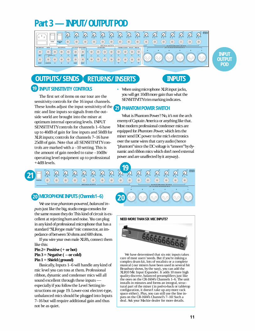
INPUT SENSITIVITY CONTROLSThe first set of items on our tour are the
sensitivity controls for the 16 input channels.These knobs adjust the input sensitivity of themic and line inputs so signals from the out-side world are brought into the mixer atoptimum internal operating levels. INPUTSENSITIVITY controls for channels 1–6 haveup to 40dB of gain for line inputs and 50dB forXLR inputs; controls for channels 7–16 have25dB of gain. Note that all SENSITIVITY con-trols are marked with a –10 setting. This isthe amount of gain needed to raise –10dBvoperating level equipment up to professional+4dB levels.
MICROPHONE INPUTS (Channels1–6)We use true phantom-powered, balanced in-
puts just like the big, studio mega-consoles forthe same reason they do: This kind of circuit is ex-cellent at rejecting hum and noise. You can plugin any kind of professional microphone that has astandard “XLR-type male” mic connector, an im-pedance of between 50 ohms and 600 ohms.
If you wire your own male XLR’s, connect themlike this:Pin 2= Positive (+ or hot)Pin 3 = Negative ( – or cold)Pin 1 = Shield (ground)
Basically, Inputs 1–6 will handle any kind ofmic level you can toss at them. Professionalribbon, dynamic and condenser mics will allsound excellent through these inputs —especially if you follow the Level Setting in-structions on page 19. Lower-cost electret-type,unbalanced mics should be plugged into Inputs7–16 but will require additional gain and thusnot be as quiet.
• When using microphone XLR input jacks,you will get 10dB more gain than what theSENSITIVITY trim marking indicates.
PHANTOM POWER SWITCHWhat is Phantom Power? No, it’s not the arch
enemy of Captain America or anything like that.Most modern professional condenser mics areequipped for Phantom Power, which lets themixer send DC power to the mic’s electronicsover the same wires that carry audio (hence“phantom” since the DC voltage is “unseen” by dy-namic and ribbon mics which don’t need externalpower and are unaffected by it anyway).
Part 3 — INPUT/OUTPUT POD
INPUTS
+4 –2513U
–10 •
UNBALANCED LINE INPUTS
+4 –2514U
–10 •
+4 –2515U
–10 •
+4 –2516U
–10 •
LEFT
RIGHT
BUSS INSERT
LEFT
RIGHT
ALT 3/4 OUT
3
6
2
5
1
4MONITOR
LEFT
RIGHT
AUX OUTPUTSMONOBAL MAIN OUT
MAINS PHANTOM+48V
6 5 4 3 2 1
LOW Z BALANCED MICROPHONE INPUTS
BALANCED/UNBALANCED LINE INPUTS
+4 –257U
–10 •
+4 –406U
–10
•
+4 –405U
–10
•
+4 –404U
–10
•
+4 –404U
–10
•
+4 –404U
–10
•
+4 –404U
–10
•
SENSITIVITYADD 8dB FORMIC INPUTS
4
8
+4 –258U
–10 •
3
7
2
6
1
5
+4 –259U
–10 •
+4 –2510U
–10 •
+4 –2511U
–10 •
+4 –2512U
–10 •
CHANNEL ACCESS TIP=OUT RING=IN
4321
AUX RETURNS
L
R
OUTPUTS/SENDS RETURNS/INSERTS19
+4 –4013U
–10 •
UNBALANCED LINE INPUTS
+4 –4014U
–10 •
+4 –4015U
–10 •
+4 –4016U
–10 •
PHANTOM
5 4 3 2 1
LOW Z BALANCED MICROPHONE INPUTS
BALANCED/UNBALANCED LINE INPUTS
+4 –407U
–10 •
+4 –406U
–10
•
+4 –405U
–10
•
+4 –404U
–10
•
+4 –403U
–10
•
+4 –402U
–10
•
+4 –401U
–10
•
SENSITIVITYADD 8dB FORMIC INPUTS
+4 –408U
–10 •
+4 –409U
–10 •
+4 –4010U
–10 •
+4 –4011U
–10 •
+4 –4012U
–10 •
6
21
20
21
20
19
NEED MORE THAN SIX MIC INPUTS?
We have determined that six mic inputs takescare of most users’ needs. But if you’re miking acomplex drum kit, lots of vocalists or a completemusical (our mixers have been used in several hitBroadway shows, by the way), you can add theXLR10 Mic Input Expander. It adds 10 more highquality discrete, balanced preamplifiers just likethe ones on the CR-1604’s Channels 1–6. The unitinstalls in minutes and forms an integral, struc-tural part of the mixer (in pod-to-back or tabletopconfiguration, it doesn’t take up any more rackspace either). Plus, you can still use the line in-puts on the CR-1604’s Channel’s 7–16! Such adeal. Ask your Mackie dealer for more details.
INPUTOUTPUT
POD

12
UNBALANCED INPUTS (Channels 7–16)These inputs are designed for mono unbal-
anced signals from instrument level to –10dBV or+4dBu. They can be used with just about any proor semipro instrument, effect or tape recorder.
MAINSIf you leave this switch in the OFF position, you
won’t hear anything. You can leave the CR-1604’sMAINS power switch ON all the time since themixer is conservatively designed so that heatbuildup isn’t a problem, even in 24-hour-a-day op-eration. Or just plug everything into a good quality,grounded power strip for 1-button turn-on.
If you leave it on all the time, don’t worry aboutthe top of the pod being warm to the touch. We usethe pod chassis as a heatsink for the voltage regula-tors which in turn dissipates a very mild amount ofheat constantly throughout the chassis. All is well.
AC RECEPTACLELook mom, no wall wart! Plug the AC power
cord in here, and enjoy the convenience of theCR-1604’s built-in power supply. The otherend goes to your power source. If some nasty
+4 –4013U
–10 •
UNBALANCED LINE INPUTS
+4 –4014U
–10 •
+4 –4015U
–10 •
+4 –4016U
–10 •
PHANTOM
5 4 3 2 1
LOW Z BALANCED MICROPHONE INPUTS
BALANCED/UNBALANCED LINE INPUTS
+4 –407U
–10 •
+4 –406U
–10
•
+4 –405U
–10
•
+4 –404U
–10
•
+4 –403U
–10
•
+4 –402U
–10
•
+4 –401U
–10
•
SENSITIVITYADD 8dB FORMIC INPUTS
+4 –408U
–10 •
+4 –409U
–10 •
+4 –4010U
–10 •
+4 –4011U
–10 •
+4 –4012U
–10 •
6
22
• DC Power is applied to Pins 2 and 3. Maximumcurrent is 10mA per microphone.
• When turned off, the phantom power circuitrytakes a moment for voltage to bleed to zero. Donot attempt to adjust your set.
• There is only one “freak” way to damage aribbon mic with phantom power. If the connec-tor on the mic cable is worn, it may not makecontact with both “hot” pins exactly at the sametime when being plugged in. This could cause amomentary DC spike that could, in turn,damage or dislodge the ribbon. To avoid thisremote possibility, always plug in ribbon micsbefore you turn the PHANTOM power switchon or off.WARNING: If you’re connecting electret-
type microphones, plug them into Channel7–16. Avoid the temptation to use Channel1–6 XLR sockets via 1/4"-to-XLR adaptorsand then turn on the PHANTOM switch. Ifyou do, the microphone will be toast. Also,don’t connect electronically balanced com-ponents such as CD players or the output ofa tape deck to the XLR inputs. Use Channel1–6 balanced 1/4" inputs instead.
BALANCED LINE INPUTS (Channels1–6)These six line inputs share circuitry (but not
phantom power) with the six mic preamps, andcan be driven by balanced and unbalanced de-vices. In other words, you can use these inputs forvirtually any signal you’ll come across, from in-strument levels to –10dBV to +4dBu, since thereis 40dB of gain available.• To connect these inputs to balanced sources,
use a Tip-Ring-Sleeve (3-conductor) plug:Tip = Positive (+ or hot)Ring = Negative ( – or cold)Sleeve = Shield (ground)
• To connect unbalanced sources to thebalanced inputs, use a mono phone plug orstandard instrument cable. The jack on theCR-1604 input will sense the plug anddisable the balancing circuits.
• Line inputs 1–6 are a good place to connectinstruments which have low output such as olderkeyboards. Or keyboards in general for that matter,since you can adjust the corresponding channelINPUT SENSITIVITY controls so the mixer hasplenty of gain, but you can still keep the keyboardvolume set around the halfway mark.
23
23
24
25
A CLOSER LOOK
WHY NO WALL WART?Building a power supply into
the CR-1604 wasn’t any picnic.But we think that you’ll appre-ciate it for several reasons:
• The CR-1604 has separateregulated power supplies for the audio, meter,12VAC lamp and microphone phantom circuits.That’s part of why it sounds so good. No wall wartcan provide this kind of sophisticated power.
• Wall warts and “line lumps” are inconvenient,generate huge hum fields, hog extra jacks on yourpower strip and get in the way when you move.
• The thin cable coming out of a wall wart orin-line power supply breaks easily, especially on theroad. Then you need a whole new one, possibly ofsome esoteric breed that’s only available from themanufacturer on alternate Thursdays via an un-listed phone number. If the rugged cord on theCR-1604 wears out, you can score one anywherefast. Except maybe in the far reaches of the galaxy.
22
MAINS PHANTOM+48V
ON OFF
24
25
26
INPUTOUTPUT
POD

13
fate befalls the cord, you can use any standardIEC cord like those found on most professionalrecorders, musical instruments and computers(for example Radio Shack #278-1257 6-ft or#278-1261 12-ft.). NOTE: Disconnecting theplug’s ground pin can be dangerous. Don’t do it.
FUSEThe CR-1604 is fused for your (and its own) pro-
tection. If you suspect a blown fuse, disconnect thepower cord, pull the fuse drawer just below the ACreceptacle and replace the fuse with a 1-amp SLOBLO fuse (or 1/2-amp SLO BLO fuse if the unit is a230V model). 230V models have a bright red230V sticker both on the shipping box and onthe mixer itself. If two fuses blow in a row, some-thing is very wrong. Call our toll-free number andfind out what to do.
CHANNEL ACCESS, TIP=OUT, RING=INThis is where you connect series processors
such as compressors, equalizer, de-essers, or filters.Since most people don’t have more than a few ofthese gadgets, we’ve included connections for justthe first eight channels. If you want to use this kindof processing on Channels 9–16, simply plug intoand out of the device before you plug into theCR-1604 channels. Connecting a processor herewill affect only the associated channel.• Tip=output (send to external device),
Ring=input (return from external device)
• The insert points are after the mic preamps,channel faders and equalizers (Post-Fader/Post-EQ). This can be modified with a littletechnical knowledge found on pages 33–34.
• CHANNEL ACCESS outputs are low-imped-ance (120-ohm) and are capable of driving allprocessors (except Cuisinart food processors).
• For best results the device should be capableof at least +18dB input/output (any profes-sional unit). Do not use “stomp box”-styledevices. They simply can’t keep up with theoperating level needed to match CR-1604performance.
• The CR-1604’s CHANNEL ACCESS jacks are ofa special design that gives more flexibility thanregular jacks. What kind of plug you use andhow far you plug it in varies the function of
CHANNEL ACCESS jacks For example, amono plug inserted only to the first click doesnot interrupt the master (main outputs,headphone output, ALT-3/4 outputs). Pluggedall the way in, it becomes a direct out andinterrupts. This may seem weird at first, butit’s the way. See page 16 for a picturedescribing the plug and inserts.
AUX RETURNS TO MASTERThis is where you connect the output of your
effects devices or, in some cases, return the signalof a multitrack tape machine/mixdown deck.
Many mixers simply have a passive input cir-cuit for AUX returns. We have active input gaincircuitry which allows use of a wider range of ex-ternal devices. The circuits will handle stereo ormono unbalanced signals at instrument level or–10dBV to +4dBu.
These eight inputs can be used for a vari-ety of effects. (For more detailed informationon functions and their relationships to practi-cal application in the production of yourmusic, see the Applications Guide in our InYour Face magazine.
BUS INSERTThese are the send and receive jacks for
inserting an effect such as final compression,limiting or EQ into the Main Left/Right Buses.Inserting a processor here will affect yourentire mix. See page 16 for a picture describ-ing the plug and inserts.
The BUS INSERTS can also be used as anoutput with no interuption to signal.
NOTE: The BUS INSERTS are pre-mainfaders. If you are using them for output, makesure the connecting device has some way toadjust incoming level.• Tip=output (send to external device),
Ring=input (return from external device)• The BUS INSERT is before the Master fader
controls and after the main L/R mix amps.• Inputs and outputs are unbalanced and
designed to work with pro devices with at least18dB of input/output.
• The BUS INSERT can also be used as a tapeout if plugged in the first “click”. Masteradjustments will not affect level.
LEFT
RIGHT
BUSS INSERT
LEFT
RIGHT
ALT 3/4 OUT
3
6
2
5
1
4MONITOR
LEFT
RIGHT
AUX OUTPUTSMONOBAL MAIN OUT
4
8
3
7
2
6
1
5
CHANNEL ACCESS TIP=OUT RING=IN
4321
AUX RETURNS
L
R
27
26
33
34
32
31
2930 28 27INPUT
OUTPUTPOD
28
29

14
BAL/UNBAL MAIN OUT – STEREOThese outputs are electronically balanced
(since they have both polarities available and arecapable of driving +4dBu lines with 28dB of head-room). They’re also low impedance.• For most music recording and PA applica-
tions, unbalanced outputs are perfectlyacceptable. Use standard cables. Forcables runs over 50 feet, you may need abalanced line to reject noise.
• Balanced output is 6dB hotter than theunbalanced outputs.
• To use these outputs in balanced applica-tions, connect a stereo phone plug as follows:
Tip = – (cold)Ring = + (hot)Sleeve = GroundWhy is the tip cold and the ring hot?! Well
if you must know there are quite a few manu-facturers that use this polarity configuration.No, you cannot go inside the CR-1604 andmerely flip the wires around; doing so wouldshort out your meters and void your warranty.If you absolutely must change the polarity tryinternally modifying a TRS adaptor or use anexternal phase reverser.
MONO MAIN OUTSame characteristics as the stereo MAIN
OUTs except that the signal combines Rightand Left Main Channels and the polarity isreversed (tip = hot, ring = cold).
ONE FINAL NOT-SO-OBVIOUS OUTPUTThe CR-1604’s stereo
PHONE jack. As you’ll seefrom the ApplicationsGuide, we recommend con-necting your monitor power
amp to this output in several cases.Its output is HOT. First turn the PHONES
fader all the way off. Then rotate the poweramp’s level controls to 12 o’clock. Now bring upthe PHONES fader gently.
If in the past you’ve had to put up with conven-tional, grungy-sounding headphone amps, youmay initially be reluctant to “trust” the CR-1604’sheadphone output. Not to worry. The sound qual-ity is exactly the same as the main outputs andwill not degrade your audio in any way.
ALT 3/4 OUTThis is where the outputs appear from the
channels that have been assigned via theMUTE/ALT switch. The post-EQ/post-fader/post-panpot/pre-aux send signals from all ofthe muted channels appear at these outputs.Output is low impedance unbalanced and isdesigned to drive any input from low to highimpedance. Maximum output level is +22dBuwith a nominal operating level of +4dBu.
NOTE: Engaging a channel’s MUTE/ALTswitch will deactivate its AUX sends. See thenext section for several nifty ALT-3/4 OUTapplications.
AUX OUTPUTSThese are low impedance unbalanced out-
puts for the signals sent from AUX sends 1through 6 (post-fader/post-EQ). Output is low im-pedance and is designed to drive ANY input fromlow to high impedance. Maximum output level is+22dBu with a nominal operating level of +4dBu.
MONITOR OUTThis is a low impedance unbalanced output
for the signals sent from the MON SEND (AUX1pre fader/pre EQ). The output is designed todrive ANY input from low to high impedance.Maximum output level is +22dBu with a nominaloperating level of +4dBu.
NEED MORE OF A GOOD THING?
You can create a 32 or 48-channel mixer withthe Mackie Designs MixerMixer combiner. It con-nects all the outputs of up to three mixers withoutlosing channels via “cascading.” You can hook uptwo or three CR-1604s together, providing youwith more of everything you love about our mixeras your budget and/or needs grow. The 1/LEFTand 2/RIGHT faders on each mixer become sub-mix faders. And we offer an optional 100mmRemote Fader to control the combined Main L/Routputs. Not satisfied with this stroke of flexibility,we’ve put together an ultra-affordable CordPackthat includes all the cables necessary to intercon-nect three CR-1604s. This way, you won’t go brokebuying 36 mono and three stereo cables piece-meal, which could add up to almost as much asthe MixerMixer itself.
33
This is NOT a typo!
34
A CLOSER LOOK
INPUTOUTPUT
POD
30
31
32

15
through a Channel Access or Stereo Bus in-sert or before/after the mixer. Processorsinclude compressors, limiters, filters or exter-nal equalizers.
ODD DUCKSSome newer, digital “Swiss Army Audio Knives”
can be switched for compression, limiting andwhatever else struck the whim of the product de-signer. Check their manuals for details. You’llprobably want to connect them based on howyou’re using them in your mix.
CONNECTING AN EFFECT WITH STEREO OUTPUTSUse two separate cables and plug into a LEFT/
RIGHT pair of an AUX return. The correspondingstereo AUX RETURN Level knob will control bothsides of the effect equally.
CONNECTING A MONO OUTPUT EFFECTIf you want a signal to return to just the right
side, plug the effect output into just the RIGHTAUX RETURN.
SEPARATE MONO EFFECTS IN L & RIf you plug different mono effects into an AUX
RETURN’s left and right jacks and press thecorresponding MONO button, you get up to eightmono returns.
CHANNEL INSERTSTo connect a processor using the CR-1604’s
CHANNEL ACCESS jacks, use tip-ring-sleeveplugs wired as shown. The “tip” plug goes to theprocessor INPUT; the “ring” plug goes to theprocessor’s OUTPUT. If you’re using these jacksas channel inserts, adjust the TRIM controls afteryou plug the processor in.
CHANNEL INSERTS AS DIRECT CHANNEL OUTSYou can also use the CHANNEL ACCESS jacks
as direct outputs from the channels (post-fader/post EQ) to feed tape decks, DAT machines orother mixers. (See drawing on following page.)
Part 4 — CONNECTION TIPSIt’s now time to begin hooking up all the cool
stuff you want to mix together. At this point, yourack mounters may want to rotate the CR-1604’sinput/output pod to its jacks-to-back position. Podrotation instructions start on page 20. If you wanteverything in yo’ face, i.e. jacks on the same planeas the controls, get our RotoPod bracket (seedetails on page 20).
Instead of being included in this manual wehave provided an incredibly detailed Applica-tions Guide with much more detailed (andcolorful) drawings than could be managed in a2-color, letter-size manual. NOTE: If you some-how lost the Applications Guide in thefrenzied heat of unpacking your CR-1604,your Mackie dealer should have some extrasstashed someplace. Or call 1-800-898-3211and we’ll send you a replacement, pronto.
EFFECTS AND PROCESSORSMost recording and PA setups use external
signal processors to enhance the sound: reverb,delay, digital delay, equalizers and compressorsare the most common, but perhaps you have aharmonizer or enhancer as well. All of thesedevices can be grouped into two categories —effects and processors, depending on what theydo and how they’re used.
EFFECTS (parallel processing)These generate additional sounds that you
add to the mix, usually by making two simulta-neous mixes: one is of the unmodified dry signalthat goes directly to the main outputs via the in-put channels; the other is an auxiliary mix thatis sent to the effects device. The output of theeffect is then mixed with the main output, usu-ally through an AUX return. The most commoneffects are reverb and digital delay.
PROCESSORS (serial processing*)These devices modify the signal and com-
pletely replace it with the processed version.Usually they are connected to only one micro-phone, instrument, or track at a time —
* — as compared to CEREAL processing, whereinwheat, rice, oats, etc. are turned into strange, alien-colored breakfasts foods named after kiddie shows.
HOOKUP

16
• Direct out with no signal interruption tomains. Push a MONO plug into a CHANNELACCESS jack until you feel it click once. Inthis configuration the channel access is actingas an independent direct out with no signalinterruption to the master.
• Direct out with signal interruption to master.Push the plug all the way into the CHANNELACCESS jack. The signal will now be inter-rupted from the master and be available at thedirect out only. Use this mode when connect-ing to the inputs of multi-track recorders.
• Effects Loop. A stereo plug wired as shownin the drawing above turns the CHANNELACCESS into a loop that will send and receiveto and from an external device using the samechannel access jack. Use this mode whenconnecting to the inputs of multi-trackrecorders.
CREATING SUB-MIXESUSING THE ALT 3/4 OUT
Surprise! The CR-1604 really has FOUR buses,not just two! The following are working examplesof how to effectively use the flexibility of theALT 3/4 OUTPUT buses. In the first example, let’simagine that you want to create a separate drumsub-mix. This setup is used to control the level ofall of the various channels that make up the drum
kit via two “sub master faders” (actually inputchannels 15 & 16 of the mixer). For purposes ofthis example, let’s assume that you have alreadyhooked up your drum mics or machine inputs toChannels 1 through 5.
EXAMPLE 1
1. Now press the MUTE ALT 3/4 buttons on thesefive input channels (They are no longer part ofyour main mix but are now destined for thesub-mix which in turn goes to the main mix.)
2. Next connect the rear panel ALT 3/4 outputsback into two other channels of the CR-1604,for example, Channels 15 and 16. These twochannels become your sub-mix level controls.
3. Pan Channel 15 HARD LEFT and Channel 16HARD RIGHT, respectively, so that thepanning of Channels 1–5 will be reflected inyour stereo sub-mix. DO NOT engage themute/alt on these channels.
4. Adjust individual levels of the five drumchannels that are part of the sub-mix by usingtheir channel faders (1, 2, 3, 4, and 5).
5. Adjust the pan position of each drum channelwith that channel’s PAN pot.
6. Control the overall level of this drum sub-mixwithin the main mix via Channel Faders15 and 16.
7. Add effects and EQ to the submix channelsif desired.
EXAMPLE 2You can also create sub-mixes without tying up
additional CR-1604 channels.1. As before, press the MUTE ALT 3/4 buttons on
the five drum Channels (1–5). These channelsare no longer part of your main mix.
2. Connect the CR-1604’s ALT 3/4 Outputs to theLEFT and RIGHT jacks of an AUX return,. Inour diagram we’ve used AUX 1, LEFT. StereoAUX RETURN 1 now controls the master drumsub-mix level.In either of these two setups, you can
instantly solo your sub-mix into your head-phones (or monitor speakers if they areconnected to the headphone output) bypressing the CR-1604’s ALT/PREVIEW but-ton or soloing the submaster channels.
Direct out with no signal interruption to master.Insert only to first “click”
Channel Insert jack
Channel Insert jack
Channel Insert jack
Direct out with signal interruption to master.Insert all the way in to the second “click”
For use as an effects loop.(TIP = SEND to effect, RING = RETURN from effects)
MONO PLUG
MONO PLUG
STEREO PLUG
“tip”
this plug connects to one of the CR-1604’s Channel Insert jacks. “ring”
tipring
sleeve
SEND to processor
RETURN from processor
(TRS plug)
HOOKUP

17
SUBMIX HOOKUP EXAMPLE 2
SUBMIX HOOKUP EXAMPLE 1
HOOKUP
+1500 RL
U
1
2
3
4
U
U
U
+1500
+1500
+1500
C
1
2
3
4
C
C
C
RL
1
2
3
4
STEREO AUX RETURNS
RL
RL MONO
AUXSOLO
0
RLPAN
SOLO
MUTEALT 3/4
OL
+ 20
U
00
0
RLPAN
SOLO
MUTEALT 3/4
OL
+20
U
00
0
RLPAN
SOLO
MUTEALT 3/4
OL
+20
U
00
0
RLPAN
SOLO
MUTEALT 3/4
OL
+20
U
00
0
RLPAN
SOLO
MUTEALT 3/4
OL
+20
U
00
MUTEthese
channels
SUB-MIX CHANNELS TO BE SUB-MIXEDsub-mix
levelset here
LEVEL BALANCE
12345
1LEFT21 LEFT
RIGHTRIGHT654
3
LOW Z BALANCED MICROPHONE INPUTSAUX RETURNBUSS INSERTAUX / MONITOR OUTPUTS
16 15 14 123456
BALANCED OR UNBALANCED LINE INPUTSUNBALANCED LINE INPUTS
L
R
MIC INPUT ADDS 8dB
ADDITIONAL GAIN
13
ALT 3-4 OUT
Press AUXSOLO to
solo sub-mix
ALT 3-4 OUT AUX RETURNSTO MASTER MIC or line inputs for submix
0
RLPAN
SOLO
MUTEALT 3/4
OL
+ 20
U
00
0
RLPAN
SOLO
MUTEALT 3/4
OL
+20
U
00
0
RLPAN
SOLO
MUTEALT 3/4
OL
+20
U
00
0
RLPAN
SOLO
MUTEALT 3/4
OL
+20
U
00
0
RLPAN
SOLO
MUTEALT 3/4
OL
+20
U
00
0
RLPAN
SOLO
MUTEALT 3/4
OL
+20
U
00
0
RLPAN
SOLO
MUTEALT 3/4
OL
+20
U
00
1615
12345
1LEFT21 LEFT
RIGHTRIGHT654
3
LOW Z BALANCED MICROPHONE INPUTSAUX RETURNS TO MBUSS INSERTALT 3-4 OUTAUX / MONITOR OUTPUTS
16 15 14 123456
BALANCED OR UNBALANCED LINE INPUTSUNBALANCED LINE INPUTS
L
R
MIC INPUT ADDS 8dB
ADDITIONAL GAIN
13
Microphones are shown but these could also be 1/4" line inputs from drum machines .
Pan Ch. 16hard RIGHT
Pan Ch. 16hard LEFT
MUTEthese
channels
SUB-MIX CHANNELS TO BE SUB-MIXED
ALT 3-4 OUT
18
CAN YOU TRUST YOUR EARS?Even if you have perfect
hearing, your ears will not al-ways give you a true idea of whatis being heard.
Expecially if you like to reallycrank your monitors while mixing. As the sessionprogresses, your ears will have a tendency to be-come accustomed and eventually numb to volumeand EQ levels. We call this phenomenon ear fatigue.The longer your session, the more ear fatigue you’llencounter.
EXAMPLE : Have you ever spent an entire nightworking on a song trying to get the EQ and volumejust right, only to find that when you listen to yourresults the next day you are horrified by the shrill-ness and lack of separation ?
This is a symptom of ear fatigue. By the end ofthe session, your ears had become accustomed tothe EQ level...so you cranked in some more mid andhighs. You also cranked the monitor amp level upevery once in a while, so by the wee hours, thingssounded distinct to you (after all, you were listeningat a VERY high volume which tends to helpdefinition...until you turn the level back down anddiscover mush at normal volume).
To avoid this, give your ears a break every houror so they can recuperate. Also, it is a good idea toresist the temptation to start out mixing with a realhigh output level because this will speed up theprocess of ear fatigue.
Your mixer can become a victim of this viciouscircle as well. Avoid inching up your levels in orderto get better separation. Watch EQ levels, too. Youmay think you can get better results by adding a lotof EQ to a guitar or keyboard part to open up themix. But eventually your CR-1604 can become over-whelmed by heavy-handed EQ and excessive outputlevels, creating what we call mixer mush.
Like we said, take a rest every once in a while. Ifthings start getting out of hand in regards to theoverall clarity of your mix, stop for awhile, go grab asoda or order in a pizza or both. What the heck. Bigstudios do it everyday !!
You’ll find these rest times are a far better useof time than if you just bear down and twist somemore knobs.
CAN YOU TRUST YOUR MONITORS?Another common problem that many new engi-
neers experience is the Big Studio Surprise . Ithappens when they take their tape to a larger studiowith better monitors.
“Gee, the bass didn’t sound that boomy at my studio”“Where’s the guitar solo?””“The cymbals sound like garbage can lids !!”
If this has ever happened to you, don’t feel bad.You can’t appreciate a color movie if all you have is
a black and white TV. And just like having a good videomonitor, the key to successful music production is anaccurate idea of what your mix really sounds like.
In order to do this properly, several things mustbe present. The first and foremost is a quality set ofcontrol room monitors and a clean power amp withplenty of dynamic headroom.
These two components are indispensable if youare to achieve the album quality product that manyof our professional users achieve with their CR-1604’s(one recent album mixed on the CR-1604 was sub-mitted for a Grammy nomination... in the classicalcategory where they’re sticklers for sound quality).
If your current monitors are an old set of POLYPOOPALA liquid cooled monoliths that you boughtoff your roommate for a hundred bucks, and youramp is the stereo receiver you bought with your pa-per route money 15 years ago, you can be assuredthat whatever you create with your CR-1604 willmost likely not sound right if played on any othersystem. Save cheap hi-fi speakers and wimpy 30-watt amps for your next garage sale.
Instead, spend the money on serious monitorspeakers and a beefy amplifier.
Actually we recommend two or three sets ofspeakers: First, a good quality pair of near fieldmonitors. This is a mandatory investment if you’reserious. They’re critical to accurate perception ofwhat you’re creating, since as you move close totrue near field monitors, the room’s acoustics nolonger become as large a factor. You can then hearexactly what’s happening. Next, get a pair of cheapmini-speakers. These simulate boom boxes, car ra-dios, etc. Finally, if you’re not out of room andmoney yet, get a pair of larger speakers with 10 or12-inch woofers. They can be pro-style studio moni-tors or just quality stereo speakers with good bassresponse. This pair gives you the other end of theconsumer spectrum and helps with adjust bass re-sponse to fit your potential audience’s hi-fi systems.
“DO I HAVE TO?” Like we said at the beginningof this manual, it’s your music. Good monitors andpower amps don’t have to cost a fortune.
DON’T DEVELOP TUNNEL HEARING Even if you have ultra-accurate monitor speak-
ers, remember, not everyone else does. Experimentwith different systems to really hear what your musicsounds like. Take your rough mixes to your friendshouse and play it on his stereo or pop a cassette ofyour mix into your car stereo. This will give you awider feel for what your studio monitor system is re-ally telling you. This is exactly why there are alwaysat least two sets of monitors in big recording studios.
A CLOSER LOOK
ASSORTED NUGGETS OF MONITORING WISDOM
CARE AND FEEDING OF YOUR CR-1604• If you’re going to use the CR-1604 in a
horizontal position (the mixer, not YOU!),cover it when not in use to prevent dust forsettling in the faders.
• To clean grunge out of the channel faders,use “canned air” which is available at photoshops. It comes in compact spray cans.
Just shove the nozzle into the fader slotand blast away. Do not use any solvents.
• To clean fingerprints, diet Pepsi andpeanut butter off the surface of the mixer,spray Windex or other ammonia-basedwindow cleaner on a rag and rub at will. Donot spray cleaner directly on the mixer lestit get into the faders.
HOOKUP

19
SENSITIVITY/LEVEL ADJUSTMENT —The long version
As we noted at the be-ginning of this manualachieving the CR-1604’s im-pressive noise andheadroom specs, requires
adjusting channel sensitiv-ity to your particular setup.
Can you run the mixerwithout this adjustment?
Sure. Chances are that you’ll get pretty goodsound. But take a moment to adjust thingsproperly and you’ll get excellent sound. Afterall, its your music.
SENSITIVITY ADJUSTMENT STEPS (repeat for each channel being used)1. If you have some idea of how the chan-
nel is going to be EQed, set it now. If not,it’s no biggie. EQ will affect levelssomewhat, but not enough to totallyknock things out of whack.
2. Rotate the channel’s PAN control hardRIGHT or hard LEFT. Leaving PAN in thecenter position will reduce level indica-tions by 6dB.
3. Set the channel’s Fader to the detentUnity position.
4. Turn the channel’s SENSITIVITY controlfully counter clockwise (+4 UNITY).That’s the small knob just above thechannel line input on the CR-1604’sinput/output pod.
5. Press the SOLO TO MAIN button on theCR-1604’s output section. (Optional.)
6. Press the SOLO button on the channelyou’re about to adjust. The level will appearon the CR-1604’s LED output meters.
7. Make some appropriate music through thatchannel. Don’t just play one sustained note,but rather jam away as you would normally.If you’re adjusting the level for a channelconnected to a microphone, have theperformer(s) sing/blow/strike/play at thelevel they’re going to record or perform at.
8. If you’ve set PAN hard left, view the levelon the left LED row. If panned hard right,the level will appear on the right LED row.
9. While the sound source is activated, turnthe channel’s SENSITIVITY controlclockwise until the level on the CR-1604meter reads about OdB.
10. Un-SOLO the channel and return thePAN control to center or however you’regoing to set it during use.
11. Repeat this procedure for each channel,using the appropriate kind of sourcewhich will be used with that particularchannel.
• When in actual use, avoid running the levelinto the CLIP range of the meter, as yoursound quality may suffer. It’s OK for the+2,+4, and +8 indicators to light up occa-sionally but only during peaks in the signalsuch as drum hits, or when the bass playeraccidently gooses one of the backup singerswith the neck of his Steinberger, etc.
• Note that you must add 10dB to themarkings on the SENSITIVITY controlwhen using the and mic inputs.
• Once you have performed this simplecalibration, there should seldom be aneed to readjust your input sensitivityunless a different kind of input is beingused with that channel.
• Adjusting the channel this way (with 0dBas maximum) is a conservative approachthat assumes things could get louderlater on. The sensitivity can be set just atad higher, if you watch levels carefullyduring use.
QUICK
START
VERY IMPORTANT
LEVELSETTINGSTEPS

20
CHANGING THE POD TORACK MOUNT POSITION
It only takes about five minutes and aPhillips-head screwdriver to change the CR-1604’s input/output pod from tabletop tojacks-to-back position.1. Remove all cords and cables from the
mixer, including a lamp if you’ve pluggedone in.
2. Place the mixer gently face down on aclean, soft surface such as a blanket orvery large dog.
3. Remove the four #6 screws securing thesmall slotted black plate on the bottom ofthe main part of the mixer. Keep track ofwhich screws go where.
4. Remove the two #8 screws on each side ofthe mixer which secure the pod. Gentlypull the pod away from the main chassis.
5. Lift the pod over the main part of themixer. Replace the slotted plate but installit turned around 180˚ with the ribboncables in the slot.
6. Lower the pod back onto the slots.7. Reinstall two #8 screws on each side to
secure the pod. DO NOT press hard whileinserting these screws.
8. Install the rack “ears” on the sides of themixer. DO NOT press hard while insertingthese screws.The BNC lamp socket is no longer acces-
sible in this position.
Remove screws here on each side.
Remove back plate
Add screws here.Then add rack rails
Replace back plateafter rotating 180 .Thread ribbon cablethrough slot
CHANGINGTHE POD
JACKS TO TOP?You can also rotate the pod so that the inputs
and outputs are on the same plane as the mainCR-1604 controls. This requires our handy dandyRotoPod bracket. It comes with its own set ofextended rack rails so that the mixer can be rackmounted in this configuration. Consult your dealerfor exciting details.

21
WARRANTY SERVICEThe complete fine print of our Warranty is
attached to the warranty card that came withyour mixer. If you can’t find it, call us andwe’ll send you another one.
Also make sure to save your sales receipt.It’s useful in establishing when you boughtthe mixer and for insurance purposes if some-one happens to borrow your entire studiowhile you were on vacation in Mazatlan.
TROUBLESHOOTINGWe haven’t included a gigantic trouble-
shooting chart with circles and arrows andcaptions on the back because our Service De-partment and support persons are here tohandle that sort of thing. Still, there are somesimple tests you can make before you call todetermine if your CR-1604 is really the cul-prit. This saves time all around and preventsyou from feeling sheepish when it turns outthat it’s really your Blort-Tronics SonicDefrabulator that’s creating the problem,and not our mixer.
Bad channelIs the channel un-muted? Fader up?
(Honest, this happens.)Unplug all Bus Insert and Channel Access
hookups.Switch output cords. For example, if the
left output is dead, switch the left and rightoutput cords at the mixer. If the problemmoves to the right, it’s not the mixer.
Bad outputIs the output un-muted? Faders up?Unplug all Bus Insert and Channel Access
hookups.Switch output cords. For example, if the
left output is dead, switch the left and rightoutput cords at the mixer. If the problemmoves to the right, it’s not the mixer.
NoiseTurn all faders and AUX returns down. If
the noise goes away, bring levels back up oneat a time, checking for noise at each step.
Unplug everything except the outputwhere the noise was detected. If the noisegoes away, plug everything back in one at atime, checking for noise at each connection.
PowerCheck the CR-1604 fuse (see page 12).
REPAIRService for the CR-1604 is only available
from the Mackie Designs factory in scenicWoodinville, Washington.
If there is a problem with your mixer:1. Review the troubleshooting suggestions at
left.
2. Call us to confirm that the CR-1604 needsrepair and to get an RA number. You musthave a Return Authorization Number(RA). Call us at 1-800-258-6883, 8 AM to 5PM Pacific time, Monday through Friday toget this number. Products shipped to uswithout an RA number will be refused.
3. If you have rotated the pod, return it to itsoriginal position (jacks pointing towardsthe back). If you’ve added a RotoPod,remove it and return the pod to originalposition. If you’ve added an XLR10,remove it.
4. Set aside the rack ears, manual and cord.We won’t need these to repair the mixer(unless you have interharmonic under-slewing bipolar crosstalk in your rack ears,a rare but particularly nasty problem...)
5. Pack the mixer in its original shippingcarton with the foam end caps in place.This is VERY IMPORTANT. If you do nothave the carton, just ask for one when youget your RA number and we’ll ship it to youpromptly.
CR-1604with pod to top
CR-1604with pod to top
Be sure to return the CR-1604 in its original“desktop” mode and remove the rack ears!
TECHSTUFF

22
6. Include a note stating:
a. Your return address and phone number
b. A brief description of the CR-1604’sproblem
7. Write the RA number in BIG PRINT on theoutside of the shipping carton.
8. Send us the mixer. We recommend U.P.S.Remember to insure the mixer. U.P.S. willhelp you with this. Ship your CR-1604 to:
Mackie Designs, attn: Service16220 Wood-Red Rd. NE
Woodinville, WA 98072, U.S.A.
9. We’ll try to fix the mixer within three busi-ness days. We send everything back prepaidU.P.S. BLUE (Second Day Air) unless you havesent your CR-1604 to us for warranty service byNEXT DAY or SECOND DAY AIR. In that case,we figure you need it fixed ASAP, so we put it atthe head of the line and ship the unit backU.P.S. RED (Next Day Air). This policy doesn’tnot apply to non-warranty service.
SPECIFICATIONSFrequency Response:
20Hz–40kHz ±1dBDistortion:
less than 0.025%, 20Hz–20kHzNoise:
Mic E.I.N.–129.0dBm, 150Ω source–133.7dBV input shortedMain output noise: –86dBuWorking S/N ratio: 90dBu(ref: +4dBu)
Max. Output:+28dBu main output balanced+22dBu all other outputs unbalanced
Dynamic Range:108dB
Max GainMic: 48dBLines 1–6: 40dBLines 7–16: 25dBMic in to balanced line out: 84dBMic in to unbalanced line out: 78dBChannel faders : 20dBAUX return: 20dBL/R master: 10dB
Channel-to-Channel Crosstalk:–85dB
Headphone Impedance/Output:20–2000 ohms/200mW.
Equalization:Hi: Shelving, ±15dB @12kHzMid: Peaking, ±12dB @2.5kHz (3.3 octave)Lo: Shelving, ±15dB @80Hz
Phantom:160mA, 10mA/CH.
Power Supply:35 Watts
Weight:18 lbs.
TECHSTUFF

23
CR-1604 DIMENSIONS(including XLR10 & MixerMixer add-ons, RotoPod bracket)
TECHSTUFF3.05"
5.5"
3.05"2.3"
2.3"
4.8"
15.8
"
15.8
"
18.2
"
0.7"
15.7"
16.7" 1.65"
16.2"
4.0"
3.0" 7.
5"
1.4" 2.3"2.6"
1.5"
2.1"
17.34"including screw heads
17.1"
9.25
"
6.4"
12.0
"
9.25
"12
.7"
12.0
"16
.1"10
rack
spa
ces
11 ra
ck s
pace
s7
rack
spa
ces
18.2
"
19.0" 16.1"
5.9"
5.9"
6.6"
6.6"
7.1"
1.6"
1.5"No
te: R
otoP
od ra
ck ra
il pla
ces
mixe
r flus
h wi
th b
otto
m ra
ck s
pace
, allo
ws g
ap a
t top
for c
ables
.
0.5"
0.5"
Remote Fader
XLR-10
CR-1604with pod to
back
podto backFLUSH
rackmountwith
XLR10
pod to
back,RECESS
rackmount
MixerMixer
RotoPodbracket,extended
rails,RECESS
rack mount
RotoPodbracket,XLR10,
extendedrails,
FLUSHrack
mount
CR-1604with
RotoPodbacket & extended
rails
CR-1604with pod to top
pod to top,FLUSH
rack mount,with
XLR-10
pod to top,
RECESS rack mount,
with XLR-10
3.8" 4.5"
Note: Dimensional drawings are shown with optional XLR10 and RotoPod.

24
CR-1604 BLOCK DIAGRAM
level up +20level up +15
0 0 0 0 0 0
0 0 0 0 0 0
0 0 0
max out +22+14 max in
-8 trim dn
MIC INPUT AUX RETURN CH. LEVEL MIX OUTPUT
OUTPUTMIX
-48 trim up
+22 max in
trim dn
-40 trim up
+22 max in
trim dn
-25 trim up
LINE INPUTCH 1–6
LINE INPUTCH 7–16
to point (B)
gain up +15fader up +20
(A) (B)
pan center -6gain dn -15(C)
INSERT EQ FADER PAN INSERT
-6 -6
0to meters
METER FEED (+0dBu @ O/P = 0 @ METERS)
MASTERCHANNELFADER
fader up +10
L/R bal max out +28
max out +22L/R unbal
from point (A)
AUX SEND
2
6 5
4 3
10 11
12 13
14 15
16
3-BAND EQUALIZER 80, 2.5K,12K
PRE/MONITOR SIGNAL
OFF TO +20dB GAIN
RING IN
TIP OUT
2-WAY SENSE
PAN
SOLO SW
AUX AMP
LEFT
SOLO
RIGHT LEFT MAIN
ALT 3-4 LEFT
RIGHT MAIN
ALT 3-4 RIGHT
AUX 1
AUX 2
AUX 3-5
AUX 4-6
AUX 1
MON
1
1
2
3
5
4
6
5-6 SHIFT
OFF TO20dBGAIN
AUX SENDS
AUX
1 A
UX 1
MON
ITOR
AUX
2 A
UX 3
AUX
4 A
UX 5
AUX
6
CHANNEL FADER
CHANNEL ACCESS FIRST CLICK=
DIRECT OUT (NO SIGNAL
CHAN MUTE (ALT 3-4)
MONITOR
SOLO
RIGHT
LEFT
INTERUPTION)
LED PEAK
8 9
2 3
1
PHANTOMPOWER
MICINPUT
GAIN TRIM:
MIC GAIN+10dB to +50dB
LINE GAIN –UNITY TO +40dB
3 1
DISCRETE MIC AMP
POINT A
2 (HOT)
CHANNELS 1-6 1
INPUT LINE
TRIM UNITY TO +25dB
NOTE: LINE INPUTS ONLY ON CHANELS 7-16, (FOR MIC INPUTS USE XLR-10 EXPANDER MODULE).
EXPANDER MIX AMP
POINT A
CHANNELS 7-16
FROM XLR10 EXPANDER
RIGHT RETURN
LEFT RETURN
BALANCE
+20dB GAIN OFF TO
GAIN
MONO
AUX RETURNS 1-4 1 2
3 4
7
LINEINPUT 10dB PAD
"You're either onthe bus or off thebus." Ken Kesey

25
TECHSTUFF
L R
MAI
N LE
FT M
AIN
RIG
HT A
LT 3
-4 L
EFT
ALT
3-4
RIG
HT S
OLO
LEFT
SOL
O RI
GHT
1
1
2
3
4
5
6
AUX 1
AUX 1
MONITOR
AUX 2 OUTPUT
AUX 3 OUTPUT
AUX 4 OUTPUT
AUX 5 OUTPUT
AUX 6 OUTPUT
+22 CLIP
+8
+4
+2 0
-4
-8
-12
-16
-20
OUTPUTMETER
METER READS INPUT CHANNEL LEVEL WHEN CHANNEL IS SOLOED.
ELECTRONICSOLO
SWITCHING
R
L
R
L
ALT 3-4
ALT 3-4 ALTPREVIEW
SOLO MIX AMPS
TIP OUT
RING IN
RING IN
TIP OUT
MAIN MIX AMPS
MASTERLEFT & RIGHT
OFF TO +10dB GAIN
BALANCED MAIN LEFT OUTPUT
+28dBu MAX BALANCED +22dBu MAX UNBALANCED
BALANCED MAIN RIGHT OUTPUT
OUTPUT MAIN MONO BALANCED
STEREO HEADPHONES OUTPUT PHONES
ANDSOLOLEVEL
L
R
TIP
RING
NOTES: 1. SWITCHES SHOWN IN
"NORMAL" POSITION.
+22dBu MAX ALL AUX SENDS
+28dBu MAX BALANCED +22dBu MAX UNBALANCED
+28dBu MAX BALANCED +22dBu MAX UNBALANCED
LEFT OUT
RIGHT OUT
L
R
ALT 3-4 MIX AMPS
LEFT BUS INSERT FIRST CLICK= DIRECT OUTPUT (NO SIGNAL INTERRUPTION)
INTERRUPTION) (NO SIGNAL DIRECT OUTPUT FIRST CLICK= INSERT RIGHT BUS
ELECTRONICSOLO
SWITCHING
(ONLY WITHSOLO TO
MAINSWITCH
ENGAGED)
MASTEROUTPUTMUTE
SWITCH
to Albuquerque
-+
-+
-+
©1995 Mackie Designs
CR-1604BLOCK DIAGRAM
Rev.

26
1. How do I get the effects into my monitors?
2. How do I get effects out the ALT 3/4 Bus?
3. How do I set up a monitor or auxiliary send master?
4. What modifications can be done to the mixer?
5. How do I perform the modifications to my mixer?
6. Can I use the Bal./Unbal. Main Outputs and MonoOutput at the same time?
7. Can I split the Main Outputs with a Y-cord?
8. Can I use the XLR Mic Inputs for line inputs?
9. How do I record with effects?
10. Why are there really only 9 questions?
(1) Q: How do I get the effects into my monitors?
A: Instead of connecting the output(s) of aneffect device to the AUX RETURN TO MASTERjacks, it should be connected to the line input(s)of unused channels. This would make the chan-nel fader(s) the AUX RETURN to main outputcontrol. This channel or channels should be setup as if it were receiving any line input signal.This means setting the proper input trim levelwith the fader at unity and setting the pan con-trol (stereo or mono). You now have the effectgoing to your main outputs.
Now to get the effect to the monitors sim-ply turn up your monitor send on thatchannel (the one you have connected the out-put of the effect to). The AUX OUT is stillconnected to the input of the effect the sameway and the individual channels are still sentto the effect the same way. The only differ-ence is how you are controlling the returnlevel of the effect.
Using this configuration you must remem-ber one important point — NEVER turn upthe AUX SEND level of the particular effecton the channel you are using as the AUX RE-TURN. This will give you a feedback loop. Forexample, if you are using AUX SEND 2 for areverb send and you are using channels 15and 16 as your stereo AUX RETURNS, youwould NEVER want to turn up AUX SEND 2on channels 15 and 16.
It may seem that you are losing inputs byconfiguring the aux returns this way but youare not. Your unused AUX RETURNS TOMASTER JACKS can now be used as inputs.By engaging the MONO switch on the AUXRETURNS you can have up to 8 mono inputs.Also, by returning the output of the effect to achannel you can now use the EQ to furtherenhance the effect.
(2) Q: How do I get effects out of the ALT 3/4 Bus?
A: You will need to perform option #1, 2, or 3in the modification sheets in order for an indi-vidual channel to be muted (sent to the ALT3/4 Bus) and still be capable of sending chan-nel information out of the auxiliary sends.
Instead of connecting the output(s) of aneffect device to the AUX RETURN TO MASTERjacks, it should be connected to the lineinput(s) of unused channels. This would makethe channel fader the auxiliary return master.
10 COMMON QUESTIONS
TECHSTUFF

27
The channel should be set up as if it werereceiving any line input signal. This means set-ting the proper input trim level with the faderat unity and setting the pan control (stereo ormono). Next you would MUTE the channelwhich would send the auxiliary returns out theALT 3/4 Bus.
(3) Q: How do I set up a monitor orauxiliary send master?
A: There are two ways:1) Insert a mono 1⁄4" cord into the auxiliary
(monitor) output jack and return the otherend of the cord to the line input of an unusedchannel. Engage the MUTE button on thechannel which will send the signal out to theALT 3/4 bus. Pan the channel hard left orright depending on which bus (3 or 4) youwant to come out of. Connect another mono1⁄4" cord from the corresponding ALT bus 3 or4 output to the input of the monitor amplifier.
or2) Insert a mono 1⁄4" cord into the auxiliary
(monitor) output jack and return the otherend of the cord to the line inputs on either ofthe channels 1–8. Connect another mono 1⁄4"cord from the corresponding channel accessjack to the input of the effect device or moni-tor amplifier. Make sure to insert the plug allthe way into the access jack on the mixer sothe signal will not go to the main L/R outputs.
Either of these 2 ways will allow you to con-trol the overall level of the auxiliary or monitorsends by using the channel fader as your mas-ter. Treat it as if it were any signal but becareful when you increase the individual chan-nel send levels because this may eventuallyclip the input stage on the master send chan-nel. If this happens, simply turn down the trimon the master send channel a little bit.
(4) Q: What modifications can be done to themixer?
Auxiliaries:Option #1: Pre EQ, Pre Fader, Pre Mute/ALTOption #2: Post EQ, Pre Fader, Pre Mute/ALTOption #3: Post EQ, Post Fader, Pre Mute/ALT(STOCK: Post EQ, Post Fader, Post Mute/ALT)
Channel Access:Option #4: Pre EQ, Pre FaderOption #5: Post EQ, Pre Fader(STOCK: Post EQ, Post Fader)
(5) Q. How do I perform the modifications to mymixer?
A: Boy, are we glad you asked! Due tooverwhelming demand we have included asection especially for Propeller-Head-Typeson the next few pages called “MODIFICA-TIONS-O-RAMA”.
(6) Q: Can I use the Bal/Unbal Main Outputs andMono Output at the same time?
A: Yes! This will not degrade the signal inany way. Remember the polarities on the mainand mono outputs when running balancedlines (see page 14 of the Owner’s Manual).
This configuration can be very useful whenan extra monitor send or a mono recording isneeded. The mono output will be thesummed output of the L/R Main Output.
It is important to remember that the MonoOutput will be the same level as the MainOutput but can be controlled at the monitoramplifier. It can also be controlled by con-necting the Mono Output to the line input ofan unused channel and Muted to the ALT 3/4Bus and then connected to the monitor am-plifier — this can be a little tricky becausewhen the main output fader levels change sodo the monitor levels.
(7) Q: Can I split the signal at the MainOutputs with Y-cords?
A: Yes! There is more than enough signalstrength available at the Main Outputs to drivethe high impedance inputs of two devices withno quality loss of the original signal. For ex-ample, if you wanted to record the MainOutput to a cassette deck as well as a DAT, twoY-cords could be used to send an identical sig-nal to both devices. This type of configurationcould be very useful for many applications.
TECHSTUFF

28
(8) Q: Can I use the XLR Mic Inputs forbalanced line inputs?
A: No and Yes. IMPORTANT!!!!!! The waythe board is configured from the factory it isnot meant to accept a line level signal at theMic Inputs. Although the mic and line inputspass through the same preamp stage, the lineinput has an internal 10dB pad. This 10dBpad can be accomplished externally by con-necting two resistors into the XLR cord beingplugged into the XLR jack.
The procedure for this is: solder one 4.7K(4,700 ohm) resistor is series with pin 2 (typi-cally +) and one 4.7K (4,700 ohm) resistor inseries with pin 3 (typically “–”). Solder theground connection as normal.
The most important thing to rememberabout connecting line inputs to the XLR MicInputs is NEVER NEVER TURN ON THEPHANTOM POWER unless you put a 22µf 50Velectrolytic capacitor in series with each re-sistor on pins 2 and 3. The positive leg of thecapacitor should be at the mixer end.
(9) Q: How do I record with effects?
A: There are three ways:1) During tracking or overdubbing, use the
Main 1/2 outputs to feed your multitrack andkeep the effects returns connected to the AuxReturns to Master jacks. This way the multi-track will get effects. Use the MUTE ALT 3/4to feed the amp and speakers for monitoringpurposes by muting (ALT 3/4) the multitrackreturns. When it is time to mix simply con-nect the Main 1/2 Outputs to the amp formonitoring the mix.
2) When using direct outputs from themixer to feed the multitrack inputs, the bestway to record with effects is to place the effectdevice in between the mixer and the multi-track. You should use the “mix” potentiometeron the effect device to determine how mucheffects are wanted on the original signal. Thiswould have to be done on a per channel basis.
3) Recording with effects can also be doneusing the ALT 3/4 outputs by muting the originalsignal and muting effects returned to channels.Connecting the ALT 3/4 outputs to the multi-track inputs gives you effects to tape. Mod #3must be done first. (See question 2.)
(10) Q: Why are there really only 9 questions?
A: There are two reasons:1) Due to an unforseen space-time rift, the
tenth answer slipped back in time before thequestion ever happened and cancelled out itsown existence.
2) This is actually a trick question. Thetenth question negates itself simply by beingthe tenth question. It’s kind of like saying,“This statement is false.” The statement isonly true if it’s false. But if it’s false then itwould be true… oh, nevermind. If you’re nota student of logic, just pretend like this ques-tion never really happened in the first place.
TECHSTUFF

29
POD
MAIN CHASSIS
MAIN CHASSIS
ab b
POD
POD
MODIFICATIONS-O-RAMAThe CR-1604 can be modified to move the
position of AUX Sends and ChannelInserts in the signal flow. Unless youhave the right tools and have tweakedwith circuitry before, leave thesemods to a pro. Our Official Word onmodifications is: “Any internalmodification of theCR-1604 MUST be per-formed by a competenttechnician. Mackie Designs ac-cepts no responsibility in the event ofimproperly performed modificationsor other damages and, in suchcases, may declare warranty privi-leges void.” Be VERY careful!
Here are the most common CR-1604 modifications, six of which are detailedon the following pages.
1. CONVERT AUX SENDS TO MONITORSENDS (Pre-EQ, Pre-Fader, Pre-Mute/ALTSwitch).
Can be done on any or all of channel strips1 to 16. Each channel modification requirescutting one or more circuit traces and addinga small jumper wire. On each strip, you canmodify Sends 2, 3, 4 or any combinationthereof. Note: Converting AUX 3 will also con-vert AUX 5; converting AUX 4 will also convertAUX 6. See the next page.
2. CONVERT AUX SENDS INTO MONITORSENDS WITH EQ (Post-EQ, Pre-Fader, Pre-Mute/ALT Switch).
Can be done on any or all of channel strips1 to 16. Each channel modification requirescutting one or more circuit traces and addinga small jumper wire. On each strip, you canmodify Sends 2, 3, 4 or any combinationthereof. Note: Converting AUX 3 will also con-vert AUX 5; converting AUX 4 will also convertAUX 6. See pg. 31.
3. CONVERT AUX SENDS TO IGNOREMUTE/ALT STATUS (Post-EQ, Post-Fader, Pre-Mute/ALT Switch).
Can be on any or all of channel strips 1–16.Converts ALL AUX sends on each channelstrip. Requires cutting a circuit trace, andadding both a small jumper wire and a20,000Ω resistor. See pg.32 of this section.
TECHSTUFF
4. CONVERT CHANNEL ACCESS (INSERTS)TO PRE-EQ / PRE-FADER.
Can be performed on any or all of the firsteight CR-1604 channel strips. Requires cuttingthree circuit traces and adding both a smalljumper wire and a 22µf/16V electrolytic cap oneach channel strip. See pg. 33 of this section.
5. CONVERT CHANNEL ACCESS (INSERTS)TO POST-EQ / PRE-FADER.
Can be performed on any or all of the firsteight CR-1604 channel strips. Requires cut-ting three circuit traces and adding both asmall jumper wire and a 22µf/16V electrolyticcap on each channel strip. See pg. 34 of thissection.
6. TIE SOLO TOGETHER ON TWO OR MORECR-1604s.
See pg. 35 of this section.
+15–15
0HI
+15–15
0MID
+12–120
LO
EQ
+20
U
00
MUTEALT 3/4
1PREAMP
EQ CH. FADER MUTEALT 3/4
INPUT
TOMAIN 1/2BUS
TOALT 3/4BUS
STOCKAUX SENDMOD 1 MOD 3MOD 2
POST-EQPOST-FADER
PRE MUTE/ALT
POST-EQPRE-FADER
PRE MUTE/ALT
PRE-EQPRE-FADER
PRE MUTE/ALT
MOD 4STOCK CHANNEL
ACCESS JACKMOD 5POST-EQ
POST-FADERPRE MUTE/ALT
POST-EQPRE-FADER
PRE MUTE/ALT
PRE-EQPRE-FADER
PRE MUTE/ALT
POST-EQPOST-FADER
POST MUTE/ALT
AUX SEND mods
CHANNEL ACCESS mods

30
Modification 1&2Modification 3&4
POD
MAIN CHASSIS
MAIN CHASSIS
ab b
POD
POD
Modification 1 — AUX SENDPRE-EQ • PRE-FADER • PRE-ALT/MUTE
This modification converts AUX Sends intopre-EQ/pre-fader/pre-ALT/mute MonitorSends. You can modify AUX 2, AUX 3 and/orAUX 4 on any or all of the CR-1604’s 16 chan-nels. Converting AUX 3 also converts AUX 5;converting AUX 4 also converts AUX 6.
1. Remove all cords from the CR-1604 andplace it face down.
2. Remove ribbon cable plate cover (a).Keep track of what screws go where!
3. Remove pod mounting bolts (b) andseparate pod from main chassis.
4. Remove bottom and side screws frommain chassis.
5. Remove main chassis cover and set itaside.
6. Cut traces to selected AUX Sends (c).7. Add jumper wires [shown as grey lines
(d) in illustration] for those AUX Sendswith cut traces. Don’t smash the wiresdown tight onto the circuit board. Letthem “arch” above if possible.
8. Replace main chassis cover and reattachtop and side screws.
9. Reconnect main chassis and pod;replace side screws.
10. Gently nudge any slack ribbon cable intothe main chassis and replace ribboncable cover.
Any internal modification of the CR-1604must be performed by a competent electronictechnician. Mackie Designs accepts no respon-sibility in the event of improperly performedmodifications or other damages and, in suchcases, may declare warranty privileges void.
* Note: Traces on different channels mayvary slightly from the drawing. (Engineeringsez channel strips are like snowflakes).
Add jumpers (d)
cut traces (c)
PRE-EQ • PRE-FADER • PRE-ALT/MUTE MODIFICATIONAUX 2 AUX 3 AUX 4
TECHSTUFF

31
Modification 2 — AUX SENDPOST-EQ • PRE-FADER • PRE-ALT/MUTE
This modification converts AUX Sends intopost-EQ / pre-fader / pre-ALT/mute MonitorSends. You can modify AUX 2, AUX 3 and/orAUX 4 on any or all of the CR-1604’s 16 chan-nels. Converting AUX 3 also converts AUX 5;converting AUX 4 also converts AUX 6.
1. Remove all cords from the CR-1604 andplace it face down.
2. Remove ribbon cable plate cover (a).Keep track of what screws go where!
3. Remove pod mounting bolts (b) andseparate pod from main chassis.
4. Remove bottom and side screws frommain chassis.
5. Remove main chassis cover and set itaside.
6. Cut traces to selected AUX Sends (c).7. Add jumper wires [shown as grey lines
(d) in illustration] for those AUX Sendswith cut traces. Don’t smash the wiresdown tight onto the circuit board. Letthem “arch” above if possible.
Modification 1&2Modification 3&4
POD
MAIN CHASSIS
MAIN CHASSIS
ab b
POD
POD
* Note: Traces on different channels mayvary slightly from the drawing. (Engineeringsez channel strips are like snowflakes).
Any internal modification of the CR-1604must be performed by a competent electronictechnician. Mackie Designs accepts no respon-sibility in the event of improperly performedmodifications or other damages and, in suchcases, may declare warranty privileges void.
8. Replace main chassis cover and reattachtop and side screws.
9. Reconnect main chassis and pod;replace side screws.
10. Gently nudge any slack ribbon cable intothe main chassis and replace ribboncable cover.
Add jumpers (d) Add jumpers (d)cut traces (c)
POST-EQ • PRE-FADER • PRE-ALT/MUTE MODIFICATION
AUX 2 AUX 3 AUX 4
TECHSTUFF

32
Modification 3 — AUX SENDPOST-EQ • POST-FADER • PRE-ALT/MUTE
This modification converts AUX Sends intopost-EQ/post-fader/pre-ALT mute MonitorSends. You can modify any or all of theCR-1604’s 16 channels. NOTE: The conver-sion affects ALL AUX Sends per channel.
1. Remove all cords from the CR-1604 andplace it facedown.
2. Remove ribbon cable plate cover (a).Keep track of what screws go where!
3. Remove pod mounting bolts (b) andseparate pod from main chassis.
4. Remove bottom and side screws frommain chassis.
5. Remove main chassis cover and set itaside.
6. Cut trace (c).7. Add jumper wire (d). Don’t smash the
jumper down onto the circuit board. Letit “arch above,” if possible.
POD
MAIN CHASSIS
MAIN CHASSIS
ab b
POD
POD
* Note: Traces on different channels mayvary slightly from the drawing. (Engineering sezchannel strips are like snowflakes).
8. Add 20,000Ω (20K), 1/4-watt resistor (e).9. Replace main chassis cover and reattach
top and side screws.10. Reconnect main chassis and pod, and
replace side screws.11. Gently nudge any slack ribbon cable into
the main chassis and replace ribboncable cover.
Any internal modification of the CR-1604must be performed by a competent electronictechnician. Mackie Designs accepts no respon-sibility in the event of improperly performedmodifications or other damages and, in suchcases, may declare warranty privileges void.
TECHSTUFF
Modification 1&2Modification 3&4
Add Jumper (d)Add resistor (e)
Cut here (c)
POST-EQ • POST-FADER • PRE-ALT/MUTE MODIFICATION

33
POD
MAIN CHASSIS
MAIN CHASSIS
ab b
POD
POD
Modification 4 — Channel InsertPRE-EQ • PRE-FADER • PRE-ALT/MUTE
This modification moves the CR-1604’sChannel Access points to pre-EQ/pre-fader.You can modify any or all of the CR-1604’s first8 channels. WARNING: This is an AdvancedDeadly, Expert Level Modification. Don’t trythis one at home!
1. Follow steps 1 through 5 at the bottomof page 31.
2. Cut traces as shown at points (a), (b)and (c) in the upper drawing at left.
3. Add jumpers (d) & (e). Don’t smash thejumper down onto the circuit board. Letit “arch” above.
4. Add a 22-microfarad/25-volt electrolyticcapacitor as shown (f) — polaritydoesn’t matter. You will need to solder awire onto one or both ends.
5. Follow steps 9 to 11 at the bottom ofpage 31.
Any internal modification of the CR-1604must be performed by a competent electronictechnician. Mackie Designs accepts no re-sponsibility in the event of improperlyperformed modifications or other damagesand, in such cases, may declare warrantyprivileges void.
* Note: Traces on different channels mayvary slightly from the drawing. (Engineeringsez channel strips are like snowflakes).
TECHSTUFF
Modification 1&2Modification 3&4
Add Jumper (d)Add Jumper (d)
Add Capacitor (d) PRE-EQ • PRE-FADER • PRE-ALT/MUTEMODIFICATION
Cut here (c)
Cut here (c)

34
Modification 5 — Channel InsertPOST-EQ • PRE-FADER • PRE-ALT/MUTE
This modification moves the CR-1604’sChannel Access points to post-EQ/pre-fader.You can modify any or all of the CR-1604’s first8 channels. WARNING: This is an AdvancedDeadly, Expert Level Modification. Don’t trythis one at home!
1. Follow steps 1 through 5 at the bottomof page 31.
2. Cut traces as shown at points (a), (b)and (c) in the lower drawing .
3. Add jumpers (d) & (e). Don’t smash thejumper down onto the circuit board. Letit “arch” above.
4. Add a 22-microfarad/16-volt electrolyticcapacitor as shown (f) polarity doesn’tmatter. You’ll need to solder a wire ontoone or both ends.
5. Follow steps 9 to 11 at the bottom ofpage 31.
POD
MAIN CHASSIS
MAIN CHASSIS
ab b
POD
POD
Modification 1&2Modification 3&4
Add Jumper (d)
Add Jumper (d)
Add Capacitor (d) POST-EQ • PRE-FADER • PRE-ALT/MUTEMODIFICATION
Cut here (c)
Cut here (c)
Cut here (c)
* Note: Traces on different channels mayvary slightly from the drawing. (Engineeringsez channel strips are like snowflakes).
Any internal modification of the CR-1604must be performed by a competent electronictechnician. Mackie Designs accepts no respon-sibility in the event of improperly performedmodifications or other damages and, in suchcases, may declare warranty privileges void.
TECHSTUFF

35
Modification 6 — Solo TieFOR MIXERMIXER APPLICATION
This modification connects the solo functionof multiple CR-1604’s.
1. Follow steps 1 through 5 at the bottomof page 31.
2. Solder an insulated wire (d) from onemixer to another at point A
3. Follow steps 9 to 11 at the bottom ofpage 31.
POD
MAIN CHASSIS
MAIN CHASSIS
ab b
POD
POD
Modification 6Main PCBsolder side
Any internal modification of the CR-1604must be performed by a competent electronictechnician. Mackie Designs accepts no respon-sibility in the event of improperly performedmodifications or other damages and, in suchcases, may declare warranty privileges void.
Add Jumper (d)
To same point on other CR-1604
A
SOLO TIE FOR MIXERMIXER APPLICATION
TECHSTUFF

36
Additionally, the mixer shall accommodatethe RotoPod Bracket Set which shall allowthe Input/Output Pod to be rotated in such away the input/outputs are on the same planewith the Main Mixing Board controls.
The mixer’s dimensions shall be 16.1" tallby 17.34" wide (including screw heads) by4.1" deep with the Input/Output Pod rotatedto top, or 15.8" tall by 17.34" wide by 4.8" deepwith the Input/Output Pod rotated to back.The rack rails shall be adjustable to allowflush mounting which shall add an extra 0.7"to respective depth measurements. Theweight in either case shall be 18 pounds.
The Input/Output Pod shall include a fe-male BNC connector for 12V AC powering andphysical attachment of a gooseneck lamp,LittleLite PN #12G or 12G-HI.
The mixer shall exactly accommodate theXLR10 add-on mic preamplifier section viamechanical and electronic connections.
6. Each mixer Input Section shall includethe following features: 4 AUX send controlsshall feed 7 separate outputs, a Monitor buttonshall change AUX 1 to either pre (monitor) orpost effects; a Shift button shall change AUX 3and 4 to AUX 5 and 6; 3 rotary equalizationcontrols (±15dB LO shelving at 80Hz, ±12dBMID peaking at 2.5kHz, ±15dB HI shelving at12kHz), L/R rotary Pan control, stereo in-placeSolo switch, Mute ALT-3/4 switch, overloadclipping LED, and dB-calibrated 45mm Chan-nel Fader with center-detent unity gainposition. The Solo switch shall maintain stereoperspective for all soloed channels and returns.The Mute switch shall cause muted channelsto be unassigned from main left/right outputand reassigned to ALT Outputs 3 & 4.
7. The mixer Main Output Section shallhave 4 Stereo AUX Returns (consisting of 4rotary Level controls, L/R Balance controls and4 mono push switches), AUX Solo switch, ALTPreview switch, Main Output Mute switch, Soloto Main switch, Left/Right Master dB-cali-brated 45mm Master Fader with center-detentunity gain position,10-step LED meter (cali-brated –20 to +8, plus CLIP), Power LED,flashing Solo LED, Stereo Headphone/SoloOutput Jack and 45mm Solo/Headphone LevelControl. The ALT Preview switch shall allowlistening to all muted channels via head-phones. The Headphone Solo Level Controlshall regulate the output level of signals ap-pearing at the Headphone Output jack andSolo as it appears at the Main Outputs.
The mixer shall be a Mackie Designs CR-1604.
(What the heck! You might run into an inquisitive,musical architect or engineer some day…)
1. The mixing console shall have a 2-partmain frame which accommodates 10 Unbal-anced and 6 Balanced Line Inputs, 6 BalancedMicrophone Inputs, 1 Balanced/UnbalancedMain Left Output, 1 Balanced/UnbalancedMain Right Output, 1 Balanced/UnbalancedMain Mono Output, 1 Monitor Output, 6 AUXOutputs, 2 ALT Outputs, 2 Bus Inserts, 4 StereoAUX Returns, 8 Channel Access Jacks and 1Stereo Headphone Output. The main frameshall be capable of mounting on a table or in astandard 19-inch rack mount and shall be en-tirely self-contained.
2. The main frame shall include two 10-LEDmeters for monitoring Main L/R Outputs orchannel level during solo, one-each OverloadClipping LED’s for each of 16 channels, Solo OnLED and Power LED.
3. The main frame shall include on its rearpanel electronically balanced mic inputs us-ing female XLR-3-type connectors to acceptnominal levels of from –50dBu to +14dBu.The main frame shall also have 16 line inputsconsisting of standard 1/4" phone jacks whichshall accept nominal levels of from –40dBu to+22dBu on Channels 1 through 6 and –25dButo +22dBu on Channels 7 through 16. Each of16 channels shall have a rotary SensitivityControl adjustable from +4dB to –40dB onChannels 1 through 6 and +4dB to –25dB onChannels 7 through 16. The main frame shallhave Stereo Bus Inserts, 4 Stereo Aux Returnsand 8 tip-out/ring-in Channel Access Inserts.There shall be a phantom power supply withseparate switch to provide DC power to allmic input connectors for remote powering ofcondenser microphones.
4. The mixer outputs shall be 1/4" phonejack; there shall be 1 Left and 1 Right MainOutputs, 1 Mono Main Output, 1 MonitorOutput, 6 AUX Outputs, Alternate Outputson buses 3 and 4, and 1 Stereo HeadphoneOutput. Maximum Main Output level shallbe +28dBu balanced (+22dBu unbalanced);all other Outputs shall be capable of +22dBumaximum output level.
5. The main frame shall be grey-black, con-sisting of two parts: a Main Mixing Board withsteel chassis, and an Input/Output Pod withaluminum/steel chassis which shall be me-chanically connected by metal screws andelectrically connected by ribbon cables. ThePod shall be designed in such a way that itmay be attached in one of two ways: 1) Withinput/outputs to the top of the mixing consoleor 2) with input/outputs to the rack of themixing console.
CR-1604 ARCHITECTS’ & ENGINEERS’SPECIFICATIONS
TECHSTUFF

37
AUXU
1
2
3
4
5
6
U
U
U
+1500
+1500
+1500
+15005/6
SHIFT
+15–15
0HI
+15–15
0MID
+12–120
LO
EQ0
RLPAN
SOLO
MUTEALT 3/4
OL
+20
U
00
MON
AUXU
1
2
3
4
5
6
U
U
U
+1500
+1500
+1500
+15005/6
SHIFT
+15–15
0HI
0MID
0LO
EQ0
RLPAN
SOLO
MUTEALT 3/4
OL
+ 20
U
00
MON
AUXU
1
2
3
4
5
6
U
U
U
+1500
+1500
+1500
+15005/6
SHIFT
+15–15
0HI
0MID
0LO
EQ0
RLPAN
SOLO
MUTEALT 3/4
OL
+20
U
00
MON
AUXU
1
2
3
4
5
6
U
U
U
+1500
+1500
+1500
+15005/6
SHIFT
+15–15
0HI
0MID
0LO
EQ0
RLPAN
SOLO
MUTEALT 3/4
OL
+20
U
00
MON
AUXU
1
2
3
4
5
6
U
U
U
+1500
+1500
+1500
+15005/6
SHIFT
+15–15
0HI
0MID
0LO
EQ0
RLPAN
SOLO
MUTEALT 3/4
OL
+20
U
00
MON
AUXU
1
2
3
4
5
6
U
U
U
+1500
+1500
+1500
+15005/6
SHIFT
+15–15
0HI
0MID
0LO
EQ0
RLPAN
SOLO
MUTEALT 3/4
OL
+20
U
00
MON
AUXU
1
2
3
4
5
6
U
U
U
+1500
+1500
+1500
+15005/6
SHIFT
+15–15
0HI
0MID
0LO
EQ0
RLPAN
SOLO
MUTEALT 3/4
OL
+20
U
00
MON
AUXU
1
2
3
4
5
6
U
U
U
+1500
+1500
+1500
+15005/6
SHIFT
+15–15
0HI
0MID
0LO
EQ0
RLPAN
SOLO
MUTEALT 3/4
OL
+20
U
00
MON
+15–15
+12–12
+15–15
+12–12
+15–15
+12–12
+15–15
+12–12
+15–15
+12–12
+15–15
+12–12
+15–15
+12–12
Ch # Ch # Ch # Ch # Ch # Ch # Ch # Ch #
CR-1604 TRACK SHEETChs____to____ Session_______________ Date___/___/___
MACK
IE DE
SIGNS
•WOO
DINV
ILLE•
WA•U
SA•1
-800
-258
-688
3

38
This is the back of a master track sheet, whichcame in the Mackie CR-1604 Manual
If you find this sheet in a copy machine, pleasereturn it to the engineer/owner of the console,

39
U
1
2
3
4
U
U
U
+1500
+1500
+1500
+1500
C
1
2
3
4
C
C
C
RL
1
2
3
4
STEREO AUX RETURNS
RL
RL
RL
LEVEL BALANCE
MONO
AUXSOLO
+10
00 00
1/LEFT 2/RIGHT LEVEL
SOLO/PHONES
MAIN OUTPUTMUTE
SOLOTO
MAIN
ALT PREVIEW
POWER
SOLOLEVEL
-20
-16
-12
-8
-4
0
+2
+4
+8
CLIP
INP
UT
TR
IMU
=U
NIT
Y G
AIN
+4
25dB
16U
–10
SENSITIVITY
+4
25dB
15U
–10
SENSITIVITY
+4
25dB
14U
–10
SENSITIVITY
+4
25dB
13U
–10
SENSITIVITY
+4
25dB
12U
–10
SENSITIVITY
+4
25dB
11U
–10
SENSITIVITY
+4
25dB
10U
–10
SENSITIVITY
+4
25dB
9U
–10
SENSITIVITY
+4
25dB
8U
–10
SENSITIVITY
+4
25dB
7U
–10
SENSITIVITY
+4
40dB
6U
–10
SENSITIVITY
+4
40dB
5U
–10
SENSITIVITY
+4
40dB
4U
–10
SENSITIVITY
+4
40dB
3U
–10
SENSITIVITY
+4
40dB
2U
–10
SENSITIVITY
CR-1604 OUTPUT, INPUTS, TRIM LEVELSSession_______________ Date___/___/___
48
37
26
15
43
21
LEFT
21
LEFT
RIG
HT
RIG
HT
65
4
MONITORRIGHT
LEFT
3
AU
X R
ETU
RN
S TO
MA
STER
ALT 3-4 O
UT
AU
X / M
ON
ITOR
OU
TPU
TS
BAL / UNBAL MAIN OUTPUTS
MONO
LR
CH
AN
NE
L AC
CE
SS
BU
SS
INS
ER
T
R L
R L
1R 1L
2R 2L
3R 3L
4R 4L
5 1
3 2
7 3
8 4
Band members wanted bass EQ turned up to +15
Monitor speakers toasted themselves at 3AM
Band members thrown out of control room
Ordered gut-bomb pizza
Ad jingle: Client was a real dork
Vocalist barfed on the Neumann
Sequencer had electronic amnesia
Ran out of patch cords
1
5 2
6 3
4
+4
40dB
1U
–10
SENSITIVITY
GA
ING
AIN
GA
ING
AIN
GA
ING
AIN
GA
ING
AIN
GA
ING
AIN
GA
ING
AIN
GA
ING
AIN
GA
ING
AIN
1
2
3
4
5
6
7
8
9
10
11
12
13
14
15
16
MACKIE DESIGNS•WOODINVILLE•WA•USA•1-800-258-6883
NOTES

40
This is the back of a master track sheet, whichcame in the Mackie CR-1604 Manual
If you find this sheet in a copy machine, pleasereturn it to the engineer/owner of the console,

41
SEMIOFFICIAL LAST PAGE

42
Whaddya say on thelast page of a manual?Well, we’d like to rollthe credits.
Film output by Art-works of Woodinville.
Set in ITC CenturyCondensed and Adobe
Futura Condensed viaPageMaker® 5.0 for the Macintosh®.
The bulk of this manual was written by RonKoliha. Technical revisions by Keith Medley,Paul Larson, Scott Garside, Jason Hill, BrianMcCully, Sara Drake and Jeff Gilbert.
Page layout and Adobe Illustrator® 5.5technical drawings by Bobby Hougham, BruceYunker, Ron Koliha, Sara Drake and GeneEndicott.
Additional “help” from P.D., the MackieCorporate Chihuahua who shredded severaldrawings at various points during the devel-opment of this manual.
We appreciate users who take the time towrite us with suggestions and corrections tothis manual. It is in a steady state of revisionand we DO read and listen to the comments.Send them to the Mackie CommunicationsDepartment, c/o James Fowler, Minister ofPropaganda (yes, that’s really his title), 16220Wood-Red Rd. NE, Woodinville, WA 98072.

43
16220 Wood-Red Rd. NE • Woodinville • WA • 98072 • USAPhone 800/258-6883 • FAX 206/487-4337 • Outside the U.S. call 206/487-4333
For literature requests only, 800/898-3211