Embed Size (px)
Citation preview

Copyright © 2008 Rockwell Automation, Inc. All rights reserved.
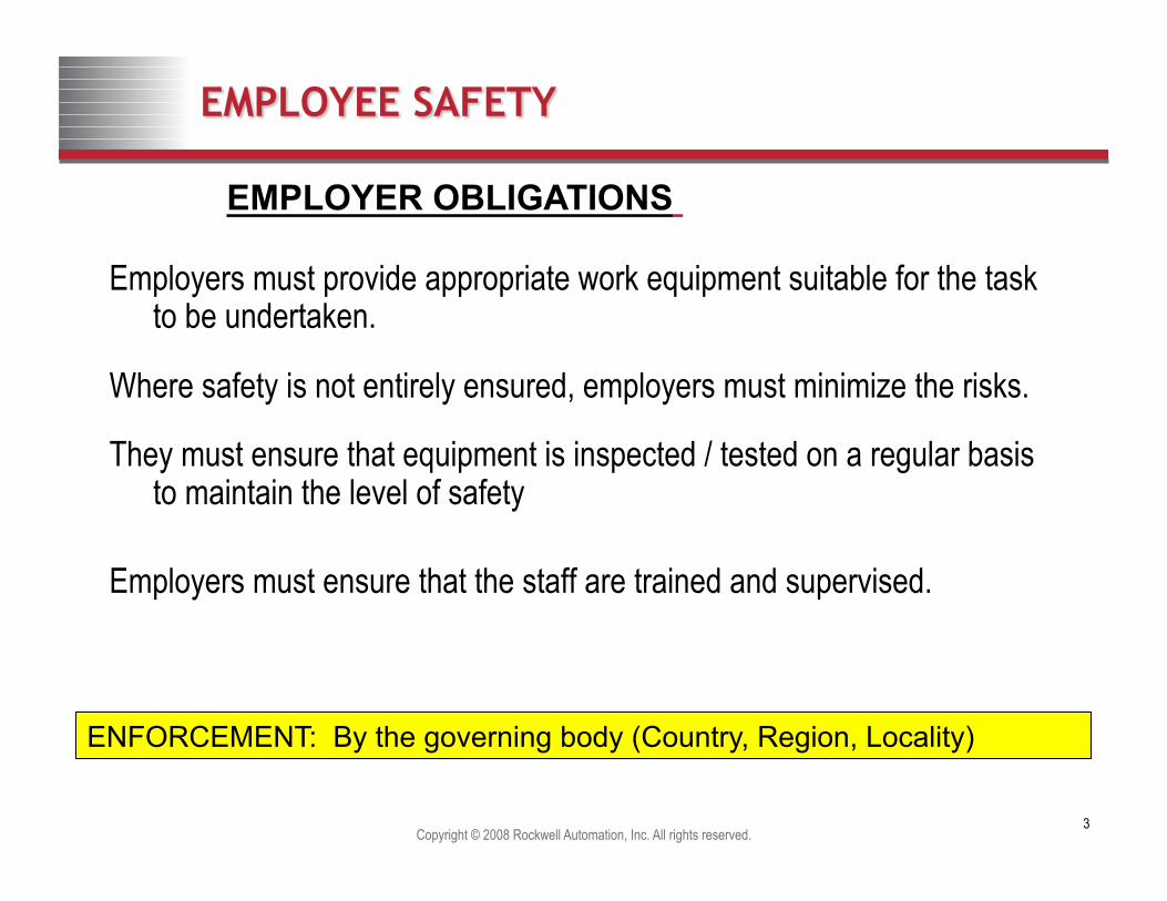
Machine Safety Life Cycle
“A Systematic, Standards Based Approach to Machine Safety”
Jeff Brys – Rockwell Automation TUV Certified Safety Engineer

Primary Goal: Prevent Injury to People
Copyright © 2012 Rockwell Automation, Inc. All rights reserved. 2
Copyright © 2008 Rockwell Automation, Inc. All rights reserved. 3
Employers must provide appropriate work equipment suitable for the task to be undertaken.
Where safety is not entirely ensured, employers must minimize the risks.
They must ensure that equipment is inspected / tested on a regular basis to maintain the level of safety
Employers must ensure that the staff are trained and supervised.
ENFORCEMENT: By the governing body (Country, Region, Locality)

Copyright © 2008 Rockwell Automation, Inc. All rights reserved. 4
Employees are required: • to use machines correctly; • to use personal protection equipment correctly; • to not modify safety measures; • to highlight dangerous working situations or faults; • to check that their work station is safe and risk-free. • follow procedures implemented by their employee
EMPLOYEES' OBLIGATIONS
Each employee is responsible for taking care of their own health and safety and that of others.
ENFORCEMENT: By the Employer

Copyright © 2011 Rockwell Automation, Inc. All rights reserved. 5
What is “Safety” Exactly?
Before we can understand what exactly we achieve through risk assessment, it is important we define safety
Q: What does the word safety really mean, and how is it achieved?
A: Safety, with respect to machinery operation is defined in IEC 62061:2005 as: “freedom from unacceptable risk”
This immediately gives us a definition for safety in terms of risk, so it now
starts to become more clear how risk assessment plays a part in achieving
safety Safety is freedom from unacceptable risk
Copyright © 2008 Rockwell Automation, Inc. All rights reserved. 6
STEP 2 SELECTION OF MITIGATION TECHNIQUES • Based on risk assessment,
system performance, and safety standards
STEP 1 RISK OR HAZARD ASSESSMENT • Identify hazards • Estimate Risks • Identify Potential Mitigation
techniques
STEP 5 OPERATIONS • Verification of system function • Production • Preventative Maintenance
• Insuring Performance after maintenance tasks
Life Cycle STEP 3 SAFEGUARDING DESIGN • Functional safety system requirements • System architecture • Safety circuit design • Validation protocol • Guarding design
STEP 4 PROJECT MANAGEMENT • Assembly • Integration testing • Commissioning • Training • Validation
Machine Safety Life Cycle

Copyright © 2008 Rockwell Automation, Inc. All rights reserved. 7
Why do risk assessments?
• Since Risk Assessments are such powerful tools to ensure machines are designed, built, operated and maintained, why do machine builders and end users not do them? Some answer that: – “Our engineers all have years experience building these machines.” – “We have done jobs like this hundreds of times.” – “We’ve gone over the details and covered every possible issue.” – “We covered the possibilities that could go wrong.” – “We have never had any safety related problems.” – “Aren’t there possible legal liability issues.” – Sharing risk will scare away customers.” – “Doing a risk assessment will cost to much money.”
Sound familiar?

Copyright © 2011 Rockwell Automation, Inc. All rights reserved. 8
The Purpose of Risk Assessment
• The process serves as an effective tool for properly identifying and assessing the real hazards involved in operating a particular machine.
• Risk assessment provides a method for determining equivalent levels of protection when designing safeguards and stating OSHA’s minor service exception.
• The process takes away the guesswork when estimating risk and prescribing safety system performance.
• Risk assessment is an active, documented process that can be filed and maintained for the entire life of the machine, and serves as documented proof of your “due diligence”.
• Risk assessment establishes the foundation and early framework for the design and implementation of an effective machine safety program.

Copyright © 2008 Rockwell Automation, Inc. All rights reserved. 9
Risk Assessment Strengths
1. Team Based Approach • Team members: Operators, Technicians, Engineering, Safety, Quality Assurance, etc. • 5 to 8 team members is optimal
3. The process is repeatable – • A common set of terms, definitions and rating systems are used • A diverse cross section of users and knowledgeable personnel are part of the process • The process flow is fixed by the risk assessment standard applied
4. Globally recognized and applied in a wide range of industries and sectors • Automotive, Financial, Aerospace, Automotive, Insurance
5. Results of the risk assessment are documented for future reference • Key element in leveraging the results and approaches to risk reduction that are defined
and identified through the risk assessment process
Why use the risk assessment method?

Copyright © 2011 Rockwell Automation, Inc. All rights reserved. 10
In Europe
• Risk assessment is a requirement for machinery directive compliance (2006/42/EC). Applies to those delivering CE compliant machinery to Europe.

Copyright © 2011 Rockwell Automation, Inc. All rights reserved. 11
As Referenced in U.S. Standards
• Risk assessment is often referenced throughout mainstream U.S. machinery safety standards:
ANSI B11.19

Copyright © 2011 Rockwell Automation, Inc. All rights reserved. 12
As Referenced in U.S. Standards
• Risk assessment is often referenced throughout mainstream U.S. machinery safety standards:
ANSI / RIA R15.06 This standard provides a detailed risk assessment methodology

Copyright © 2007 Rockwell Automation, Inc. All rights reserved. 13
Rockwell Automation’s team/task based risk assessment methodology: ANSI/RIA R15.06 -1999
(ANSI – American National Standards Institute) (RIA – Robotic Industries Association)
Other Risk Assessment methodologies published include: • ANSI B11.TR3 – Risk Assessment Technical Report • MIL STD 882 – Standard Practice for System Safety • ISO 12100 – Principles of Risk Assessment • IEC 61508 – Functional Safety of Electrical / Electronic/Programmable
electronic Control Systems • IEC 62061 – Safety of Machinery, Functional safety of safety-related electrical,
electronic and programmable electronic control systems • ISO 13849 (EN954) – Safety of Machinery, Safety related parts of the control
system • CSA Z-434 – Robotic Standard (ANSI RIA R15.06-1999)
Standards – Risk Assessment

Copyright © 2008 Rockwell Automation, Inc. All rights reserved. 14
Copyright © 2007 Rockwell Automation, Inc. All rights reserved.
14
Risk Assessment
• Identify hazards associated with human interaction to processes or machines
• Estimate the risk level associated with the hazards • Evaluate the risk level to determine if the risk level is acceptable
Risk Assessment is a method or process designed to:
Assessing Risk is about identifying exposure to hazards

Copyright © 2008 Rockwell Automation, Inc. All rights reserved. 15
Hazards per B11.19 (not complete list)
Copyright © 2007 Rockwell Automation, Inc. All rights reserved.
15
What is a hazard?
Definition: potential source of harm.

Copyright © 2008 Rockwell Automation, Inc. All rights reserved. 16
Risk Assessment
• With the Risk Reduction Technique applied, the task/hazard is reevaluated to identify, estimate and evaluate any residual risks
• This process is repeated until an acceptable or tolerable level of risk is achieved

Copyright © 2008 Rockwell Automation, Inc. All rights reserved. 17
Identifying Hazards: Assume No Safeguards Are In Place
• The first pass of the hazard identification is assuming no safeguards are in place such as: – Welding Mask – Welding gloves – Welding chaps – Bricks to keep truck
from rolling – Grounded welder – Dry ground – Redundant /
Diverse supports – Fire Extinguisher

Copyright © 2008 Rockwell Automation, Inc. All rights reserved. 18
What is Risk?
• Definition of risk: “combination of the probability of occurrence of harm and the severity of that harm.” – Made up of two, maybe three parts
• Severity – how severe • Probability – how likely to occur • Sometimes a third element is involved in the “possibility of avoidance.”
TEXT
How Likely?
Chances
How Often?
Frequency
How Bad?
Consequences
Risk

ANSI B11.0:2010 Annex H
19

ANSI B11.0:2010 Annex H
20

ANSI B11.0:2010 Annex H
21

Copyright © 2008 Rockwell Automation, Inc. All rights reserved. 22
Risk Assessment Worksheet
Risk Assessment Worksheet Sheet #: Machine: Panel Assembly Cell
Task Potential
Incidents /Accidents
Prior to Safeguards Potential Safeguards
Recom-mendations
With Safeguards Severity of Injury
Exposure
Avoid ance
Risk Reduction Category
Exposure Avoid
ance Sev erity Residual Risk
The Risk Assessment Process will guide the risk assessment team as the Risk Assessment Worksheet is filled out.
#1 #2 #3 #4 #6 #5 #7 #8 #9 #10 #11 #12

Copyright © 2008 Rockwell Automation, Inc. All rights reserved. 23
Copyright © 2007 Rockwell Automation, Inc. All rights reserved.
23
ANSI RIA R15.06 Risk Estimation Definitions
FACTOR CATEGORY CRITERIA
Severity
Exposure
Avoidance
S2
S1
E2
E1
A2
A1
Serious Injury
Slight Injury
Frequent Exposure
Infrequent Exposure
Not Likely
Likely
Normally irreversible or Fatality – requires more than First Aid.
Normally reversible – requires First Aid.
Exposure to the Hazard more than once per hour
Exposure to the Hazard less than once per day or per shift
Cannot move out of the way, or inadequate reaction time, or Robot speed greater than 250mm / sec
Can move out of the way, or sufficient warning / reaction time, or Robot speed less than 250mm/sec
Table 1 - From ANSI R15.06-1999

Copyright © 2008 Rockwell Automation, Inc. All rights reserved. 24
ANSI / RIA R15.06 – 1999 Risk Graph
SIMPLE (Cat B) SINGLE CHANNEL (Cat 1)
SINGLE CHANNEL (Cat 1)
SINGLE CHANNEL with monitoring (Cat 2)
CONTROL RELIABLE (Cat 4/3)
CONTROL RELIABLE (Cat 4) R1 R2A
R2B
R4
R2C
R3A
R3B
S2
E2
E1
A2
A1
A2
A1
S1
E2
E1
A2
A1
A2
A1
SINGLE CHANNEL with monitoring (Cat 2) R2B
SIMPLE (Cat B)
START
ANSI EN-954 Severity
Exposure Avoidance Risk
Rating
Circuit Performance Requirements

Copyright © 2008 Rockwell Automation, Inc. All rights reserved. 25
ANSI B11.19 Control Reliability
Per ANSI B11.19, Section 5.5.1, Control Reliability: When required by the performance requirements of the safeguarding, the device, system, or interface shall be designed, constructed, and installed such that a single component failure within the device, interface or system shall prevent a successive machine cycle. This requirement does not apply to those components whose function does not affect safe operation of the machine tool.
Per ANSI B11.19, Section 2.12, Definitions: Control Reliability is defined as a method of ensuring the integrity of the performance of guards, devices, or control systems.

Copyright © 2011 Rockwell Automation, Inc. All rights reserved. 26
Functional Safety Standards
“Generic” Electrical Control Systems
IEC 61508
“Machinery” Electrical Control
Systems IEC 62061
“Process” Electrical Control
Systems
IEC 61511
“Machinery” Control Systems
(All technologies)
ISO 13849-1: 2006 replaces EN 954-1 in
November 2009
SIL
PL

Copyright © 2012 Rockwell Automation, Inc. All rights reserved. 27
ISO EN 13849-1(2006) Risk graph – familiar but different
S = Severity of injury S1 = slight (normally reversible injury) S2 = Serious (normally irreversible injury including death F = Frequency and/or exposure time to the hazard F1 = Seldom to less often and/or the exposure time is short F2 = Frequent to continuous and/or the exposure time is long P= Possibility of avoiding the hazard or limiting the harm P1 = possible under specific conditions P2 = Scarcely possible a,b,c,d,e = Estimates of safety-related Performance Level Risk Parameters
ISO 13849 - 1

SIL ASSIGNMENT IEC 62061 Functional safety of electrical, electronic and programmable control systems for machinery

Risk Categories RIA 15.06
R1
Risk Categories As determined from
the risk assessment
Risk Categories to Circuit Performance
R2A
R2B
R2B
R2C
R3A
R3B
R4 a
b
b
c
c
d
d
e
Performance Levels
ISO13849-1
Control Reliable (4.5.4)
Control Reliable (4.5.4)
Single CH with Monitoring (4.5.3)
Single CH with Monitoring (4.5.3)
Single CH (4.5.2)
Single CH (4.5.2)
Simple (4.5.1)
Simple (4.5.1)
Categories From
EN954
ANSI B11.19
Cat B
Cat 4
Cat 3+
Cat 2
Cat 2
Cat 1
Cat 1
Cat B
SIL Levels IEC 62061
-
SIL 3
SIL 2/3
SIL 2/1
SIL 1
SIL 1
SIL 1
SIL 1/-

Keeping People Safe Around Machinery
Rule #1: If access to the machine
is needed, turn it off
Rule #2: If the machine is running,
keep people away LOTO / Isolate Hazardous Energy Machine Guarding

Energy Isolation vs. Machine Guarding
Machine Maintenance • Regulation: Lockout / Tagout or Energy
Isolation • Requirement: Release stored energy • Tasks: Isolation of Mechanical / Electrical
Equipment for Service and Maintenance
Production Operation • Regulation: Machine Guarding • Requirement: Protect operators from machine
production hazards • Tasks: Operator Interaction for Regular
Machine Production
Minor servicing must be routine, repetitive and integral to the operation of the system.
Minor Servicing Exception • minor jams, minor tool changes & adjustments, exchange
Regulation: Machine Guarding or alternative protection means • Requirement: Protect operators from machine production hazards
when performing minor servicing • Tasks: Minor servicing such as clearing jams, loading parts, etc.
Minor Service Exception to Lockout Tagout
Must provide alternative Measures that offer effective protection
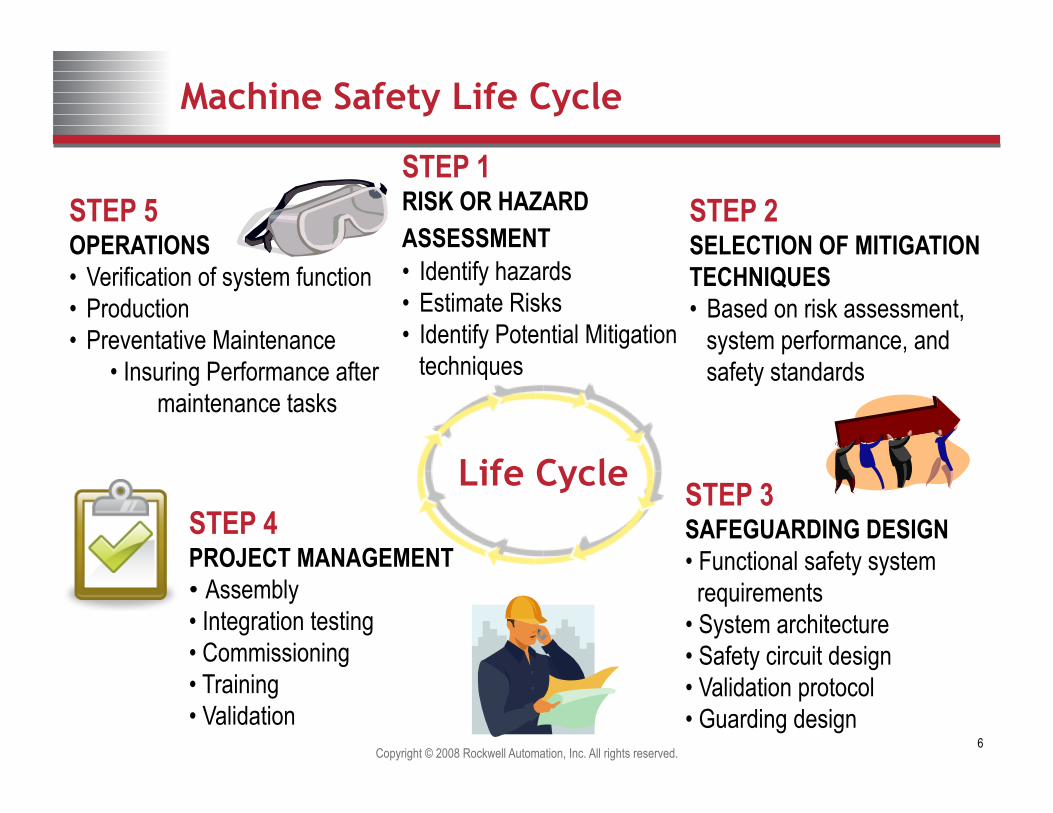
If machine access is required, 2 choices:
Lock-out/Tag-out - Energy Isolation
Alternative means – Machine Safety

33
Subject Regulatory Requirement What must I do?
Consensus Standard How will I do it?
Control of Hazardous Energy
29 CFR 1910.147 Control of Hazardous Energy
ANSI/ASSE Z244.1 Control of Hazardous Energy Lockout/Tagout and Alternative Methods NFPA 79 Electrical Standard for Industrial Machinery
Safeguarding During Normal Operation
29 CFR 1910 Subpart O Machinery and Machine Guarding
ANSI B11.19 Performance Criteria for safeguarding ISO 13857 Safety of machinery — Safety distances to prevent hazard zones being reached…
Safeguarding During Routine Service / Set-Up Activities
29 CFR 1910.147 (a)(2)(ii) “Minor Service Exception”
ANSI/ASSE Z244.1 Control of Hazardous Energy Lockout/Tagout and Alternative Methods ANSI B11.0 Safety of Machinery – General Requirements and Risk Assessment ANSI B11.19 Performance Criteria for safeguarding
Consensus Standards - Examples

Copyright © 2008 Rockwell Automation, Inc. All rights reserved. 34
OSHA CFR 1910 Standards
• CFR 1910.147 – Lockout / Tagout Standard – Applies when employees perform maintenance and service to production equipment – Requires that unexpected energization of equipment be prevented by removing all energy from a machine
and locking the energy sources in the off-state whenever an employee must place any part of their body in a potentially hazardous location
• CFR 1910 Subpart O – Machine Guarding Standards – Applies when employees operate and work around equipment that is in the production state – Requires that employers provide safeguarding of hazards that could cause injury or illness to employees
• Exception to Lockout/Tagout – Applies when employees perform “minor servicing” to equipment
– Requires that employers provide effective “alternative measures” to safeguard employees
Question: What OSHA standards apply to machine guarding of production equipment?

Copyright © 2008 Rockwell Automation, Inc. All rights reserved. 35
Copyright © 2007 Rockwell Automation, Inc. All rights reserved.
35
Risk Reduction
Design it out
Fixed enclosing guard
Monitoring Access / Interlocked Gates
Awareness Means, Training and Procedures (Administrative)
Personal protective equipment
Most Effective
Least Effective
Hierarchy of Protective Measures

ANSI B11.0:2010 Table 3
36
Eliminate Balance/Optimize

Safety is a System View ...
• The energy sources related to the hazards* on a machine will be controlled by one or more “safety loops” that monitor and manage its’ supply of energy
– *As determined by the risk assessment
• Each safety product must be applied as a whole to effectively reduce risk – Safety is the sum of its parts and safety is only as good as its weakest link
• The complexity of the inputs (sensors) and outputs (actuators) and the flexibility of the control will determine the type of logic solver
– Stand-alone relay, modular relay or safety PLC
Copyright © 2012 Rockwell Automation, Inc. All rights reserved. 37
Logic Solver (e.g. Safety Relay or PLC)
Actuator(s) (e.g. Motor)
Sensors (e.g. Door Interlock)
Sensors (e.g. E-Stop)
Sensors (e.g. Speed Reference)
Actuator(s) (e.g. clamp)
Main Goals • RISK REDUCTION • Simplify LOTO • Improve MTTR • Increase Machine Availability • Improve Cost of Doing Business
INPUTS LOGIC SOLVING OUTPUTS

38
Input
Safety Logic is Like Machine Logic
CONTROL SYSTEM
Sensors [e.g. Interlock switch]
LOGIC SOLVER Output
Actuators [e.g. Contactors
Valves]

39
The structure and behaviour of the safety function under fault conditions Designated Architecture Category B
Requirements • Basic Safety principles
• Withstand expected influences
Behaviour under fault conditions A fault can cause a loss of the safety function.
Typical implementation
Machine Control
Contactor Motor
Sensor ? Designed to product standards e.g. IEC 60947-5-2 (not
specific safety standards) Designed for environment and electrical safety aspects
e.g., IEC 60204-1
Structure Category B

40
The structure and behaviour of the safety function under fault conditions Designated Architecture Category 1
Requirements • Category B
• Well tried components • Well tried safety principles
Behaviour under fault conditions A fault can cause a loss of the safety function.
Typical implementation
Machine Control
Contactor Motor
Guard interlock switch
Structure Category 1
41
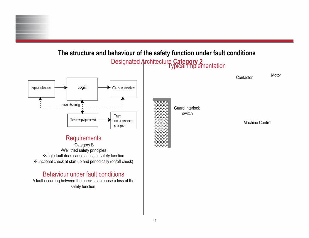
The structure and behaviour of the safety function under fault conditions Designated Architecture Category 2
Requirements • Category B
• Well tried safety principles • Single fault does cause a loss of safety function
• Functional check at start up and periodically (on/off check)
Behaviour under fault conditions A fault occurring between the checks can cause a loss of the
safety function.
Typical implementation
Machine Control
Contactor Motor
Guard interlock switch
Safety monitoring relay with start up check
Structure Category 2

Copyright © 2012 Rockwell Automation, Inc. All rights reserved. 42
A1 S11 S52 S12 13 23 33 41
S21 S22 S34 A2 14 24 34 42
K1
K2
K1
RESET
M
Safety Device Monitoring
Safety Relay Contactor
INPUT
LOGIC
OUTPUT
Single Channel W/Monitoring / EN 954 Cat 2
Relay – Rated to Cat 2,3 or 4 Checks for Failures after the
release of the RESET PB
Gate Switches Can Be Wired in Series

43
The structure and behaviour of the safety function under fault conditions Designated Architecture Category 3
Requirements • Category B
• Well tried safety principles • Single fault does not cause a loss of safety function
• Where practicable that fault should be detected
Behaviour under fault conditions Accumulation of undetected faults can cause a loss of the safety
function.
Typical implementation
Machine Control
Contactors with mechanically linked contacts
Motor
Safety monitoring relay
Contactor monitoring
Guard interlock switches
Structure Category 3

Copyright © 2012 Rockwell Automation, Inc. All rights reserved. 44
A1 S11 S52 S12 13 23 33 41
S21 S22 S34 A2 14 24 34 42
K1
K2
K2
K1
RESET
M
Safety Device Monitoring
Safety Relay Contactors
INPUT
LOGIC
OUTPUT
Control Reliable Circuit / EN 954 Cat 3
Relay – Rated to Cat 3 or 4 Checks for Failures after the
release of the RESET PB
Gate Switches Can Be Wired in Series

45
The structure and behaviour of the safety function under fault conditions Designated Architecture Category 4
Requirements • Category B
• Well tried safety principles • Single fault does not cause a loss of safety function
• An accumulation of faults does not cause a loss of safety function
Behaviour under fault conditions Faults will be detected in time to prevent a loss of safety function
Typical implementation
Machine Control
Contactors with mechanically linked contacts
Motor
Safety monitoring
relays
Contactor monitoring
Guard interlock switches
Structure Category 4
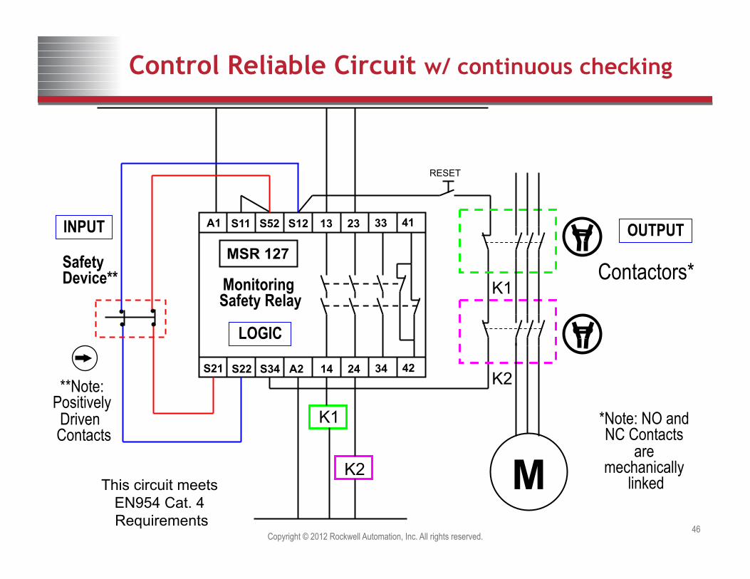
Copyright © 2012 Rockwell Automation, Inc. All rights reserved. 46
A1 S11 S52 S12 13 23 33 41
S21 S22 S34 A2 14 24 34 42
MSR 127
K1
K2
K2
K1
RESET
M
Safety Device** Monitoring
Safety Relay Contactors*
INPUT
LOGIC
OUTPUT
Control Reliable Circuit w/ continuous checking
This circuit meets EN954 Cat. 4 Requirements
*Note: NO and NC Contacts
are mechanically
linked
**Note: Positively Driven Contacts

S12 S22 A1 13 23 S34
S11 S21 L12 L11 A2 14 24 Y32
11 21 33
12 22 34
K1
Motor
T3 T2 T1
K1
OL
L1 L2 L3
K2
24V
0V / Common
Monitoring Safety Relay
Reset
Stop
Start
Seal-in Circuit
V+
V-
To PLC
To PLC
K2
Start

S12 S22 A1 13 23 S34
S11 S21 L12 L11 A2 14 24 Y32
11 21 33
12 22 34
K1
Motor
T3 T2 T1
K1
OL
L1 L2 L3
K2
24V
0V / Common
Monitoring Safety Relay
Reset
Stop
Start
Seal-in Circuit
V+
V-
To PLC
To PLC
K2
Demand on the Safety Circuit

S12 S22 A1 13 23 S34
S11 S21 L12 L11 A2 14 24 Y32
11 21 33
12 22 34
K1
Motor
T3 T2 T1
K1
OL
L1 L2 L3
K2
24V
0V / Common
Monitoring Safety Relay
Reset
Stop
Start
Seal-in Circuit
V+
V-
To PLC
To PLC
K2
Reset

Copyright © 2011 Rockwell Automation, Inc. All rights reserved. 50 50
Functional Safety Machine Life Cycle
5. Maintain and Improve
1. Hazard or Risk Assessment
4. Installation and Validation
2. Functional Requirements
3. Design and Verification
System design based on integrating safety and machine functionality.

Copyright © 2008 Rockwell Automation, Inc. All rights reserved. 51
Thank you for participating!


![Measuring skewness: we don not assume muchscientiairanica.sharif.edu/article_21733_30bc978aa49bda0bd083595… · academic articles, including Aucremanne et al. [16], Brys et al. [17],](https://img.dokumen.tips/doc/110x75/5eacf2285a526d6eca5bfabb/measuring-skewness-we-don-not-assume-academic-articles-including-aucremanne-et.jpg)

![WELCOME [vppparegion3.org]vppparegion3.org/ppts/HuPOrientationTrainingVPPP3.pdfWhat Is Human Performance (HuP) Birth In The Aviation Field Used At Nuclear Utilities For Several Years](https://img.dokumen.tips/doc/110x75/5af4e60d7f8b9a9e598d5a5a/welcome-is-human-performance-hup-birth-in-the-aviation-field-used-at-nuclear.jpg)