Embed Size (px)
Citation preview

1.4.22
DC 3-wireM8sn 1.2 mm
Wiring diagrams see page 1.0.6
For sensors with cable please append cablematerial and length to ordering code!PVC, standard length 3 m = 03PUR, standard length 3 m = PU-03
Housing sizeMounting (see notes starting p. 1.0.11)Rated operating distance sn
Assured operating distance sa
NO
NC
Rated operational voltage Ue
Supply voltage UB
Voltage drop Ud at IeRated insulation voltage Ui
Rated operational current IeNo-load supply current I0 max.Off-state current IrPolarity reversal protectedShort circuit protectedPermissible load capacitance
Repeat accuracy RAmbient temperature range Ta
Frequency of operating cycles fUtilization categoryFunction indicator
Degree of protection per IEC 60529
Housing materialMaterial of sensing faceConnectionNo. of wires × cross-section
Recommended connectorO-Ring/spare part numberSupport ring/spare part number
Pressure rated to
M8×1flush
1.2 mm0...1 mm
BES 516-324-SA 17-
24 V DC10...30 V DC
≤ 1.5 V75 V DC200 mA≤ 20 mA≤ 80 µA
yesno
≤ 0.5 µF
≤ 5 %–25...+70 °C
1500 HzDC 13
no
IP 68 per BWN Pr. 20
Stainless steelPA 12Kabel
3×0.14 mm²
10 bar
InductiveSensors
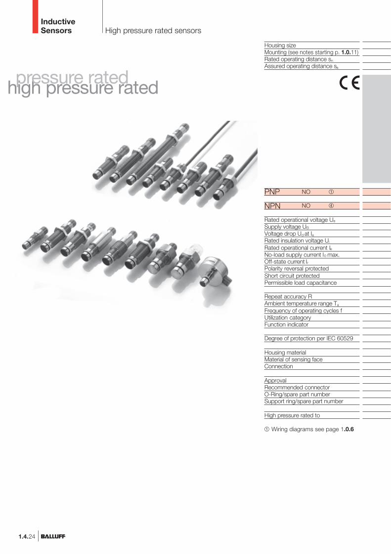
Inductive Sensors –pressure rated up to100 bar and high pressurerated up to 500 bar.
In the wide range ofhydraulic applications, highpressure proximity switchesare exposed to many hostileenvironments.
Numerous applications inhydraulic cylinders andvalves have resulted in thismodel-rich sensor line. Whatare your requirements?
Medium-resistant housingmaterials and a specialsealing process result inpressure ratings from 3 to500 bar depending on themodel.
Different housing diametersand thread lengths can bedeveloped according to thespecific requirements of theapplication.
The output amplifier is builtin, so that no accessorydevices are necessary andthe switch may be connecteddirectly to the coil of a relay.Pressure-tight proximityswitches are available withmolded-in cable or withplug-in connector.
Installation of pressure/high pressurerated sensors with O-ring
Example for BES 516-300-S 270-S 4-D:
d1: ∅ of bore for switch head∅ 10H8 = ∅ 10+0,022
d2: nominal thread diameter M12×1 6HL: recommended insertion depth L ≥ 0.8×d2
0.8×12 = 9.6
Thread undercut D DIN 76
0.6 × O-ring-cord diameter
Assembly direction
PNP
high pressure ratedpressure rated
1.4.23
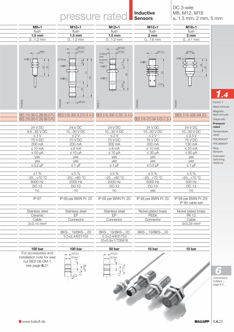
DC 3-wireM8, M12, M18sn 1.5 mm, 2 mm, 5 mm
M12×1flush
2 mm0...1.6 mm
BES 516-370-SA 9-E5-C-S 4
24 V DC10...30 V DC
≤ 2 V75 V DC200 mA≤ 10 mA≤ 30 µA
yesyes
≤ 0.5 µF
≤ 5 %–25...+70 °C
5000 HzDC 13
yes
IP 68 per BWN Pr. 20
Nickel plated brassPEEK
Connector
BKS-_ 19/BKS-_ 20
10 bar
M18×1flush
5 mm0...4.1 mm
BES 516-326-SA 23-
24 V DC10...30 V DC
≤ 3.5 V75 V DC130 mA≤ 20 mA≤ 80 µA
yesyes
≤ 1 µF
≤ 5 %–25...+70 °C
500 HzDC 13
no
IP 68 per BWN Pr. 20/IP 60 cable exit
Nickel plated brassPA 12Cable
3×0.34 mm²
10 bar
pressure ratede ratede rated InductiveSensors
Connectors,holders ...page 6.2 ...
6
M12×1flush
1.5 mm0...1.2 mm
BES 516-300-S 291-S 4-D
24 V DC10...30 V DC
≤ 2 V75 V DC200 mA≤ 8 mA≤ 10 µA
yesyes
≤ 1 µF
≤ 5 %–25...+80 °C
2000 HzDC 13
no
IP 68 per BWN Pr. 20
Stainless steelEP
Connector
BKS-_ 19/BKS-_ 205.3×2.4/631753
10×5.9×1/705918
50 bar
M8×1flush
1.5 mm0...1.2 mm
BES 516-300-S 289-B0-D-PU-BES 516-300-S 292-B0-D-PU-
24 V DC9.6...55 V DC
≤ 1 V75 V DC200 mA≤ 10 mA≤ 50 µA
yesyes
≤ 0.2 µF
±1 %–25...+70 °C
6000 HzDC 13
no
IP 67
Stainless steelCeramicCable
3×0.14 mm²
100 barFor accessories and
installation note for sealnut BES 08-DM-1
see page 6.31
M12×1flush
1.5 mm0...1.2 mm
BES 516-300-S 270-S 4-D
24 V DC10...30 V DC
≤ 2 V75 V DC200 mA≤ 8 mA≤ 10 µA
yesyes
≤ 1 µF
≤ 5 %–25...+80 °C
2000 HzDC 13
no
IP 68 per BWN Pr. 20
Stainless steelEP
Connector
BKS-_ 19/BKS-_ 205.3×2.4/631753
100 bar
O-Ring
O-Ringwithsupportring
1.4Factor 1
Weld immune
Magneticfield immune
Diagnostic
Pressurerated
Temperaturerated
PROXINOX®
PROXIMAX®
RingSensors
Extendedswitchingdistance
www.balluff.de
High pressure rated sensors
Housing sizeMounting (see notes starting p. 1.0.11)Rated operating distance sn
Assured operating distance sa
NO
NO
Rated operational voltage Ue
Supply voltage UB
Voltage drop Ud at IeRated insulation voltage Ui
Rated operational current IeNo-load supply current I0 max.Off-state current IrPolarity reversal protectedShort circuit protectedPermissible load capacitance
Repeat accuracy RAmbient temperature range Ta
Frequency of operating cycles fUtilization categoryFunction indicator
Degree of protection per IEC 60529
Housing materialMaterial of sensing faceConnection
ApprovalRecommended connectorO-Ring/spare part numberSupport ring/spare part number
High pressure rated to
Wiring diagrams see page 1.0.6
InductiveSensors
NPN
PNP
1.4.24
high pressure ratedpressure rated

1.4.25
DC 3-wireM12sn 1.5 mm
M12×1flush
1.5 mm0...1.2 mm
BES 516-300-S 135-S 4-D
24 V DC10...30 V DC
≤ 1.5 V75 V DC200 mA≤ 10 mA≤ 10 µA
yesyes
≤ 0.5 µF
≤ 5 %–25...+80 °C
1000 HzDC 13
no
IP 68 per BWN Pr. 20
Stainless steelEP
Connector
BKS-_ 19/BKS-_ 205.85×2.4/63659410×5.9×1/705918
500 bar
high pressure ratede ratede rated InductiveSensors
O-Ringwithsupportring
Connectors,holders ...page 6.2 ...
6
M12×1flush
1.5 mm0...1.2 mm
BES 516-300-S 164-S 4-D
24 V DC10...30 V DC
≤ 1.5 V75 V DC200 mA≤ 10 mA≤ 10 µA
yesyes
≤ 0.5 µF
≤ 5 %–25...+80 °C
1000 HzDC 13
no
IP 68 per BWN Pr. 20
Stainless steelEP
Connector
BKS-_ 19/BKS-_ 205.3×2.4/631753
10×5.9×1/705918
500 bar
M12×1flush
1.5 mm0...1.2 mm
BES 516-300-S 163-S 4-D
BES 516-300-S 242-S 4-D
24 V DC10...30 V DC
≤ 1.5 V75 V DC200 mA≤ 10 mA≤ 10 µA
yesyes
≤ 0.5 µF
≤ 5 %–25...+80 °C
1000 HzDC 13
no
IP 68 per BWN Pr. 20
Stainless steelEP
Connector
BKS-_ 19/BKS-_ 205.3×2.4/631753
10×5.9×1/705918
500 bar
M12×1flush
1.5 mm0...1.2 mm
BES 516-300-S 298-S 4-D
24 V DC10...30 V DC
≤ 1.5 V75 V DC200 mA≤ 10 mA≤ 10 µA
yesyes
≤ 0.5 µF
≤ 5 %–25...+80 °C
1000 HzDC 13
no
IP 68 per BWN Pr. 20
Stainless steelEP
Connector
cULusBKS-_ 19/BKS-_ 205.85×2.4/63659410×5.9×1/705918
500 bar
M12×1flush
1.5 mm0...1.2 mm
BES 516-300-S 300-S 4-D
24 V DC10...30 V DC
≤ 1.5 V75 V DC200 mA≤ 10 mA≤ 10 µA
yesyes
≤ 0.5 µF
≤ 5 %–25...+80 °C
1000 HzDC 13
no
IP 68 per BWN Pr. 20
Stainless steelEP
Connector
BKS-_ 19/BKS-_ 205.3×2.4/631753
10×5.9×1/705918
500 bar
O-Ringwithsupportring
O-Ringwithsupportring
O-Ringwithsupportring
O-Ringwithsupportring
low hysteresis
1.4Factor 1
Weld immune
Magneticfield immune
Diagnostic
Pressurerated
Temperaturerated
PROXINOX®
PROXIMAX®
RingSensors
Extendedswitchingdistance
www.balluff.de
Also available asinductive highpressure rated- anddiagnostic sensor,see page 1.4.18

1.4.26
DC 3-wireM12sn 1.5 mm
Housing sizeMounting (see notes starting p. 1.0.11)Rated operating distance sn
Assured operating distance sa
NO
NC
NO
Rated operational voltage Ue
Supply voltage UB
Voltage drop Ud at IeRated insulation voltage Ui
Rated operational current IeNo-load supply current I0 max.Off-state current IrPolarity reversal protectedShort circuit protectedPermissible load capacitance
Repeat accuracy RAmbient temperature range Ta
Frequency of operating cycles fUtilization categoryFunction indicator
Degree of protection per IEC 60529
Housing materialMaterial of sensing faceConnectionNo. of wires × cross-section
Recommended connectorO-Ring/spare part numberSupport ring/spare part number
High pressure rated to
InductiveSensors
M12×1flush
1.5 mm0...1.2 mm
BES 516-300-S 265-S 4-D
24 V DC10...30 V DC
≤ 2 V75 V DC200 mA≤ 8 mA≤ 10 µA
yesyes
≤ 1 µF
≤ 5 %–25...+80 °C
2000 HzDC 13
no
IP 68 per BWN Pr. 20
Stainless steelEP
Connector
BKS-_ 19/BKS-_ 205.3×2.4/631753
10×5.9×1/705918
500 bar
M12×1flush
1.5 mm0...1.2 mm
BES 516-300-S 249-S 4-D
24 V DC10...30 V DC
≤ 2 V75 V DC200 mA≤ 8 mA≤ 10 µA
yesyes
≤ 1 µF
≤ 5 %–25...+80 °C
2000 HzDC 13
no
IP 68 per BWN Pr. 20
Stainless steelEP
Connector
BKS-_ 19/BKS-_ 205.3×2.4/631753
10×5.9×1/705918
500 bar
Also available asNAMUR sensor, foruse in hazardouszones, see page 1.4.34
M12×1flush
1.5 mm0...1.2 mm
BES 516-300-S 162-S 4-D
24 V DC10...30 V DC
≤ 2 V75 V DC200 mA≤ 8 mA≤ 10 µA
yesyes
≤ 1 µF
≤ 5 %–25...+80 °C
2000 HzDC 13
no
IP 68 per BWN Pr. 20
Stainless steelEP
Connector
BKS-_ 19/BKS-_ 205.3×2.4/631753
10×5.9×1/705918
500 bar
M12×1flush
1.5 mm0...1.2 mm
BES 516-300-S 281-S 4-D
24 V DC10...30 V DC
≤ 1.5 V75 V DC200 mA≤ 10 mA≤ 80 µA
yesyes
≤ 1 µF
≤ 5 %–25...+80 °C
1000 HzDC 13
no
IP 68 per BWN Pr. 20
Stainless steelEP
Connector
BKS-_ 19/BKS-_ 205.3×2.4/631753
10×5.9×1/705918
500 bar
O-Ringwithsupportring
O-Ringwithsupportring
O-Ringwithsupportring
O-Ringwithsupportring
PNP
NPN
Wiring diagrams see page 1.0.6
For sensors with cable pleaseappend cable length to orderingcode!Standard length 3 m = 03

1.4.27
DC 3-wireM12sn 1.5 mm
M12×1flush
1.5 mm0...1.2 mm
BES 516-300-S 240-D-PU-
24 V DC10...30 V DC
≤ 2 V75 V DC200 mA≤ 8 mA≤ 10 µA
yesyes
≤ 1 µF
≤ 5 %–25...+80 °C
2000 HzDC 13
no
IP 68 per BWN Pr. 20
Stainless steelEP
Cable, PUR3×0.14 mm²
5.85×2.4/63659410×5.9×1/705918
500 bar
InductiveSensors
O-Ringwithsupportring
Connectors,holders ...page 6.2 ...
6
M12×1flush
1.5 mm0...1.2 mm
BES 516-300-S 205-D-PU-
24 V DC10...30 V DC
≤ 2 V75 V DC200 mA≤ 8 mA≤ 10 µA
yesyes
≤ 1 µF
≤ 5 %–25...+80 °C
2000 HzDC 13
no
IP 68 per BWN Pr. 20
Stainless steelEP
Cable, PUR3×0.14 mm²
5.3×2.4/63175310×5.9×1/705918
350 bar
M12×1flush
1.5 mm0...1.2 mm
BES 516-300-S 162-D-PU-
24 V DC10...30 V DC
≤ 2 V75 V DC200 mA≤ 8 mA≤ 10 µA
yesyes
≤ 1 µF
≤ 5 %–25...+80 °C
2000 HzDC 13
no
IP 68 per BWN Pr. 20
Stainless steelEP
Cable, PUR3×0.14 mm²
5.3×2.4/63175310×5.9×1/705918
500 bar
M12×1flush
1.5 mm0...1.2 mm
BES 516-300-S 262-S 4-D
24 V DC10...30 V DC
≤ 2 V75 V DC200 mA≤ 8 mA≤ 10 µA
yesyes
≤ 1 µF
≤ 5 %–25...+90 °C
2000 HzDC 13
no
IP 68 per BWN Pr. 20
Stainless steelEP
Connector
BKS-_ 19/BKS-_ 205.3×2.4/631753
10×5.9×1/705918
500 bar
M12×1flush
1.5 mm0...1.2 mm
BES 516-300-S 135-D-PU-BES 516-300-S 178-D-PU-
24 V DC10...30 V DC
≤ 1.5 V75 V DC200 mA≤ 10 mA≤ 10 µA
yesyes
≤ 0.5 µF
≤ 5 %–25...+80 °C
1000 HzDC 13
no
IP 68 per BWN Pr. 20
Stainless steelEP
Cable, PUR3×0.14 mm²
5.85×2.4/63659410×5.9×1/705918
500 bar
O-Ringwithsupportring
O-Ringwithsupportring
O-Ringwithsupportring
1.4
O-Ringwithsupportring
Factor 1
Weld immune
Magneticfield immune
Diagnostic
Pressurerated
Temperaturerated
PROXINOX®
PROXIMAX®
RingSensors
Extendedswitchingdistance
www.balluff.de
high pressure ratede ratede rated

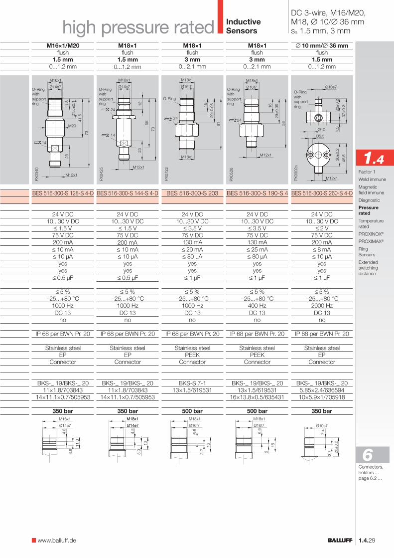
DC 3-wireM16, M16/∅ 19 mmsn 1.5 mm
1.4.28
Housing sizeMounting (see notes starting p. 1.0.11)Rated operating distance sn
Assured operating distance sa
NO
NC
Rated operational voltage Ue
Supply voltage UB
Voltage drop Ud at IeRated insulation voltage Ui
Rated operational current IeNo-load supply current I0 max.Off-state current IrPolarity reversal protectedShort circuit protectedPermissible load capacitance
Repeat accuracy RAmbient temperature range Ta
Frequency of operating cycles fUtilization categoryFunction indicator
Degree of protection per IEC 60529
Housing materialMaterial of sensing faceConnectionNo. of wires × cross-section
Recommended connectorO-Ring/spare part numberSupport ring/spare part number
High pressure rated to
Wiring diagrams see page 1.0.6Switching distance seepage 1.0.10
InductiveSensors
M16×1/∅ 19 mmflush
1.5 mm0...1.2 mm
BES 516-300-S 129-S 4-D
24 V DC10...30 V DC
≤ 1.5 V75 V DC200 mA≤ 10 mA≤ 10 µA
yesyes
≤ 0.5 µF
≤ 5 %–25...+80 °C
1000 HzDC 13
no
IP 68 per BWN Pr. 20
Stainless steelEP
Connector
BKS-_ 19/BKS-_ 2011×1.8/703843
14×11.1×0.7/505953
350 bar
M16×1flush
1.5 mm0...1.2 mm
BES 516-300-S 149-S 4-DBES 516-300-S 156-S 4-D
24 V DC10...30 V DC
≤ 1.5 V75 V DC200 mA≤ 10 mA≤ 10 µA
yesyes
≤ 0.5 µF
≤ 5 %–25...+80 °C
1000 HzDC 13
no
IP 68 per BWN Pr. 20
Stainless steelEP
Connector
BKS-_ 19/BKS-_ 2011×1.5/709137
14×11.6×1.5/709136
350 bar
M16×1flush
1.5 mm0...1.2 mm
BES 516-300-S 237-D-PU-
24 V DC10...30 V DC
≤ 1.5 V75 V DC200 mA≤ 10 mA≤ 10 µA
yesyes
≤ 0.5 µF
≤ 5 %–25...+80 °C
1000 HzDC 13
no
IP 68 per BWN Pr. 20
Stainless steelEP
Cable, PUR3×0.34 mm²
11×1.8/70384314×11.1×0.7/505953
350 bar
O-Ringwithsupportring
O-Ringwithsupportring
M16×1flush
1.5 mm0...1.2 mm
BES 516-300-S 152-S 4-D
24 V DC10...30 V DC
≤ 1.5 V75 V DC200 mA≤ 10 mA≤ 10 µA
yesyes
≤ 0.5 µF
≤ 5 %–25...+80 °C
1000 HzDC 13
no
IP 68 per BWN Pr. 20
Stainless steelEP
Connector
BKS-_ 19/BKS-_ 2011×1.8/703843
14×11.1×0.7/505953
350 bar
O-Ringwithsupportring
PNP
O-Ringwithsupportring
1.4.29
∅ 10 mm/∅ 36 mmflush
1.5 mm0...1.2 mm
BES 516-300-S 260-S 4-D
24 V DC10...30 V DC
≤ 2 V75 V DC200 mA≤ 8 mA≤ 10 µA
yesyes
≤ 1 µF
≤ 5 %–25...+80 °C
2000 HzDC 13
no
IP 68 per BWN Pr. 20
Stainless steelEP
Connector
BKS-_ 19/BKS-_ 205.85×2.4/63659410×5.9×1/705918
350 bar
InductiveSensors
O-Ringwithsupportring
Connectors,holders ...page 6.2 ...
6
M18×1flush
1.5 mm0...1.2 mm
BES 516-300-S 144-S 4-D
24 V DC10...30 V DC
≤ 1.5 V75 V DC200 mA≤ 10 mA≤ 10 µA
yesyes
≤ 0.5 µF
≤ 5 %–25...+80 °C
1000 HzDC 13
no
IP 68 per BWN Pr. 20
Stainless steelEP
Connector
BKS-_ 19/BKS-_ 2011×1.8/703843
14×11.1×0.7/505953
350 bar
M18×1flush
3 mm0...2.1 mm
BES 516-300-S 190-S 4
24 V DC10...30 V DC
≤ 3.5 V75 V DC130 mA≤ 25 mA≤ 80 µA
yesyes
≤ 1 µF
≤ 5 %–25...+80 °C
400 HzDC 13
no
IP 68 per BWN Pr. 20
Stainless steelPEEK
Connector
BKS-_ 19/BKS-_ 2013×1.5/619531
16×13.8×0.5/635431
500 bar
M18×1flush
3 mm0...2.1 mm
BES 516-300-S 203
24 V DC10...30 V DC
≤ 3.5 V75 V DC130 mA≤ 20 mA≤ 80 µA
yesyes
≤ 1 µF
≤ 5 %–25...+80 °C
1000 HzDC 13
no
IP 68 per BWN Pr. 20
Stainless steelPEEK
Connector
BKS-S 7-113×1.5/619531
500 bar
O-Ring
O-Ringwithsupportring
O-Ringwithsupportring
1.4
M16×1/M20flush
1.5 mm0...1.2 mm
BES 516-300-S 128-S 4-D
24 V DC10...30 V DC
≤ 1.5 V75 V DC200 mA≤ 10 mA≤ 10 µA
yesyes
≤ 0.5 µF
≤ 5 %–25...+80 °C
1000 HzDC 13
no
IP 68 per BWN Pr. 20
Stainless steelEP
Connector
BKS-_ 19/BKS-_ 2011×1.8/703843
14×11.1×0.7/505953
350 bar
O-Ringwithsupportring
DC 3-wire, M16/M20,M18, ∅ 10/∅ 36 mmsn 1.5 mm, 3 mm
Factor 1
Weld immune
Magneticfield immune
Diagnostic
Pressurerated
Temperaturerated
PROXINOX®
PROXIMAX®
RingSensors
Extendedswitchingdistance
www.balluff.de
high pressure ratede ratede rated
DC 3-wireM12sn 1.5 mm
1.4.30
InductiveSensors
Housing sizeMounting (see notes starting p. 1.0.11)Rated operating distance sn
Assured operating distance sa
NO
Rated operational voltage Ue
Supply voltage UB
Voltage drop Ud at IeRated insulation voltage Ui
Rated operational current IeNo-load supply current I0 max.Off-state current IrPolarity reversal protectedShort circuit protectedPermissible load capacitance
Repeat accuracy RAmbient temperature range Ta
Frequency of operating cycles fUtilization categoryFunction indicator
Degree of protection per IEC 60529
Housing materialMaterial of sensing faceConnection
Recommended connectorO-Ring/spare part numberSupport ring/spare part number
High pressure rated to
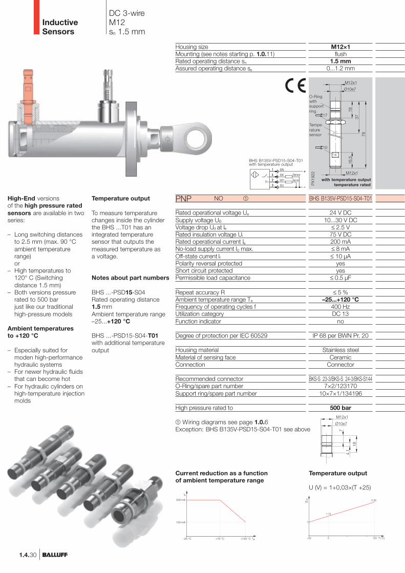
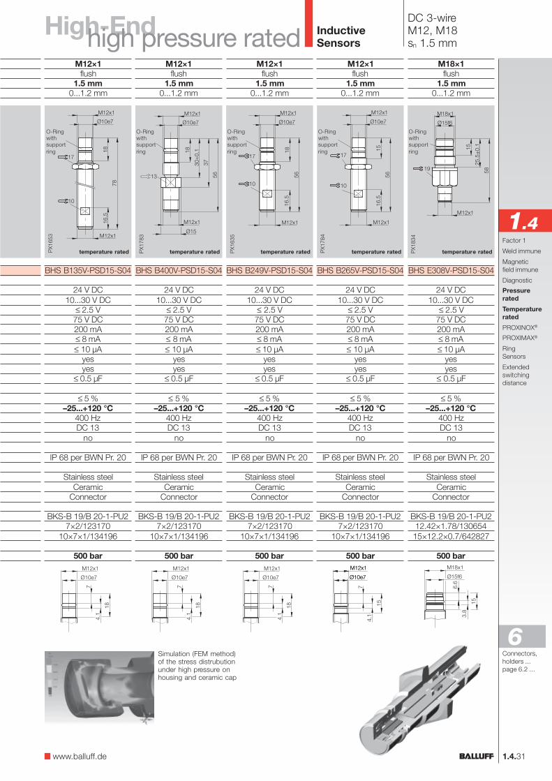
PNPHigh-End versionsof the high pressure ratedsensors are available in twoseries:
– Long switching distancesto 2.5 mm (max. 90 °Cambient temperaturerange)or
– High temperatures to120° C (Switchingdistance 1.5 mm)
– Both versions pressurerated to 500 barjust like our traditionalhigh-pressure models
Ambient temperaturesto +120 °C
– Especially suited formoden high-performancehydraulic systems
– For newer hydraulic fluidsthat can become hot
– For hydraulic cylinders onhigh-temperature injectionmolds
Temperature output
To measure temperaturechanges inside the cylinderthe BHS ...T01 has anintegrated temperaturesensor that outputs themeasured temperature asa voltage.
Notes about part numbers
BHS ...-PSD15-S04Rated operating distance1.5 mmAmbient temperature range–25...+120 °C
BHS ...-PSD15-S04-T01with additional temperatureoutput
M12×1flush
1.5 mm0...1.2 mm
BHS B135V-PSD15-S04-T01
24 V DC10...30 V DC
≤ 2.5 V75 V DC200 mA≤ 8 mA≤ 10 µA
yesyes
≤ 0.5 µF
≤ 5 %–25...+120 °C
400 HzDC 13
no
IP 68 per BWN Pr. 20
Stainless steelCeramic
Connector
BKS-S 23-3/BKS-S 24-3/BKS-S1447×2/123170
10×7×1/134196
500 bar
with temperature outputtemperature rated
Temperature output
U (V) = 1+0,03×(T +25)
M12x1
PX1
922
16.5
18
10
37
78
M12x1
Ø10e7
17
Current reduction as a functionof ambient temperature range
–25 °C +75 °C
200 mA
100 mA
+120 °C
BHS B135V-PSD15-S04-T01with temperature output
+1
4
2
3
1
4
2
3
BN
BK
WH
BU
TempT
Sensor
T (°C)–25 0
1
120
1.75
5.35U(V)
Wiring diagrams see page 1.0.6Exception: BHS B135V-PSD15-S04-T01 see above
O-Ringwithsupportring
Tempe-raturesensor
High-EndM12×1flush
1.5 mm0...1.2 mm
BHS B265V-PSD15-S04
24 V DC10...30 V DC
≤ 2.5 V75 V DC200 mA≤ 8 mA≤ 10 µA
yesyes
≤ 0.5 µF
≤ 5 %–25...+120 °C
400 HzDC 13
no
IP 68 per BWN Pr. 20
Stainless steelCeramic
Connector
BKS-B 19/B 20-1-PU27×2/123170
10×7×1/134196
500 bar
M12×1flush
1.5 mm0...1.2 mm
BHS B135V-PSD15-S04
24 V DC10...30 V DC
≤ 2.5 V75 V DC200 mA≤ 8 mA≤ 10 µA
yesyes
≤ 0.5 µF
≤ 5 %–25...+120 °C
400 HzDC 13
no
IP 68 per BWN Pr. 20
Stainless steelCeramic
Connector
BKS-B 19/B 20-1-PU27×2/123170
10×7×1/134196
500 bar
M12×1flush
1.5 mm0...1.2 mm
BHS B400V-PSD15-S04
24 V DC10...30 V DC
≤ 2.5 V75 V DC200 mA≤ 8 mA≤ 10 µA
yesyes
≤ 0.5 µF
≤ 5 %–25...+120 °C
400 HzDC 13
no
IP 68 per BWN Pr. 20
Stainless steelCeramic
Connector
BKS-B 19/B 20-1-PU27×2/123170
10×7×1/134196
500 bar
M12×1flush
1.5 mm0...1.2 mm
BHS B249V-PSD15-S04
24 V DC10...30 V DC
≤ 2.5 V75 V DC200 mA≤ 8 mA≤ 10 µA
yesyes
≤ 0.5 µF
≤ 5 %–25...+120 °C
400 HzDC 13
no
IP 68 per BWN Pr. 20
Stainless steelCeramic
Connector
BKS-B 19/B 20-1-PU27×2/123170
10×7×1/134196
500 bar
PX1
653
16.5
18
10
78M12x1
Ø10e7
M12x1
17
M12x1
17
10
1516
.5
Ø10e7
56
PX1
784
M12x1
PX1
635
1816
.5
56
M12x1
17
10
Ø10e7
M12x1
1.4.31
InductiveSensors
Connectors,holders ...page 6.2 ...
6
1.4
M18×1flush
1.5 mm0...1.2 mm
BHS E308V-PSD15-S04
24 V DC10...30 V DC
≤ 2.5 V75 V DC200 mA≤ 8 mA≤ 10 µA
yesyes
≤ 0.5 µF
≤ 5 %–25...+120 °C
400 HzDC 13
no
IP 68 per BWN Pr. 20
Stainless steelCeramic
Connector
BKS-B 19/B 20-1-PU212.42×1.78/13065415×12.2×0.7/642827
500 bar
O-Ringwithsupportring
DC 3-wireM12, M18sn 1.5 mm
temperature rated temperature ratedtemperature rated temperature rated temperature rated
Simulation (FEM method)of the stress distrubutionunder high pressure onhousing and ceramic cap
Factor 1
Weld immune
Magneticfield immune
Diagnostic
Pressurerated
Temperaturerated
PROXINOX®
PROXIMAX®
RingSensors
Extendedswitchingdistance
www.balluff.de
high pressure ratede ratede rated
O-Ringwithsupportring
O-Ringwithsupportring
O-Ringwithsupportring
O-Ringwithsupportring

M12×1flush
2.5 mm0...2 mm
BHS B135V-PSD25-S04-003
24 V DC10...30 V DC
≤ 2.5 V75 V DC200 mA≤ 8 mA≤ 10 µA
yesyes
≤ 0.5 µF
≤ 5 %–25...+90 °C
400 HzDC 13
no
IP 68 per BWN Pr. 20
Stainless steelCeramic
Connector
BKS-B 19/B 20-1-PU27×2/123170
10×7×1/134196
500 bar
1.4.32
InductiveSensors
Housing sizeMounting (see notes starting p. 1.0.11)Rated operating distance sn
Assured operating distance sa
NO
Rated operational voltage Ue
Supply voltage UB
Voltage drop Ud at IeRated insulation voltage Ui
Rated operational current IeNo-load supply current I0 max.Off-state current IrPolarity reversal protectedShort circuit protectedPermissible load capacitance
Repeat accuracy RAmbient temperature range Ta
Frequency of operating cycles fUtilization categoryFunction indicator
Degree of protection per IEC 60529
Housing materialMaterial of sensing faceConnection
Recommended connectorO-Ring/spare part numberSupport ring/spare part number
High pressure rated to
Wiring diagrams see page 1.0.6
PNP
extendedtemperature range
Current reduction as a functionof ambient temperature range
Switching distance 2.5 mm
– Even more function reserve– For compensating cylinder tolerances
Note about part number
BHS ...-PSD25-S04-003Rated operating distance 2.5 mmAmbient temperature range –25...+90 °C
IeIe
Ta+90 °C+75 °C–25 °C
200 mA
167 mA
DC 3-wireM12sn 2.5 mm
PX1
653
16.5
18
10
78
M12x1
Ø10e7
M12x1
17
O-Ringwithsupportring

M12×1flush
2.5 mm0...2 mm
BHS B265V-PSD25-S04-003
24 V DC10...30 V DC
≤ 2.5 V75 V DC200 mA≤ 8 mA≤ 10 µA
yesyes
≤ 0.5 µF
≤ 5 %–25...+90 °C
400 HzDC 13
no
IP 68 per BWN Pr. 20
Stainless steelCeramic
Connector
BKS-B 19/B 20-1-PU27×2/123170
10×7×1/134196
500 bar
M12×1flush
2.5 mm0...2 mm
BHS B400V-PSD25-S04-003
24 V DC10...30 V DC
≤ 2.5 V75 V DC200 mA≤ 8 mA≤ 10 µA
yesyes
≤ 0.5 µF
≤ 5 %–25...+90 °C
400 HzDC 13
no
IP 68 per BWN Pr. 20
Stainless steelCeramic
Connector
BKS-B 19/B 20-1-PU27×2/123170
10×7×1/134196
500 bar
M12×1flush
2.5 mm0...2 mm
BHS B249V-PSD25-S04-003
24 V DC10...30 V DC
≤ 2.5 V75 V DC200 mA≤ 8 mA≤ 10 µA
yesyes
≤ 0.5 µF
≤ 5 %–25...+90 °C
400 HzDC 13
no
IP 68 per BWN Pr. 20
Stainless steelCeramic
Connector
BKS-B 19/B 20-1-PU27×2/123170
10×7×1/134196
500 bar
M12x1
17
10
1516
.5
Ø10e7
56
PX1
784
M12x1
PX1
635
1816
.5
56
M12x1
17
10
Ø10e7
M12x1
M12×1flush
2.5 mm0...2 mm
BHS B249V-PSD25-BP00,2-S04-003
24 V DC10...30 V DC
≤ 2.5 V75 V DC200 mA≤ 8 mA≤ 10 µA
yesyes
≤ 0.5 µF
≤ 5 %–25...+90 °C
400 HzDC 13
no
IP 67 per BWN Pr. 20
Stainless steelCeramic
0.2 m cable (PUR) with connector
BKS-B 19-1-PU27×2/123170
10×7×1/134196
500 bar
1.4.33
Connectors,holders ...page 6.2 ...
6
1.4
InductiveSensors
DC 3-wireM12sn 2.5 mm
extendedtemperature range
extendedtemperature range
extendedtemperature range
extendedtemperature range
Factor 1
Weld immune
Magneticfield immune
Diagnostic
Pressurerated
Temperaturerated
PROXINOX®
PROXIMAX®
RingSensors
Extendedswitchingdistance
Simulation (FEM method)of the stress distrubutionunder high pressure onhousing and ceramic cap
www.balluff.de
High-Endhigh pressure ratede ratede rated
O-Ringwithsupportring
O-Ringwithsupportring
O-Ringwithsupportring
O-Ringwithsupportring

DC 2-wireM12sn 1.5 mm
InductiveSensors
1.4.34
NAMUR
Electrical sensors to NAMURspecification consistessentially of an oscillatorwith a dampable oscillatorcoil and a demodulator.
The high pressure ratedsensorBES 516-300-S 266-S 4is used among other thingsfor end-of-travel monitoringof hydraulic cylinders orposition feedback on valves.
This sensor can be used inconjunction with suitableswitch amplifiers such asfrom BARTEC (see nextpage) in explosive systemsor Zone 1 and Zone 2 areas.The switch amplifier must beinstalled outside the explosi-ve area.
Wiring diagram
M12×1flush
1.5 mm0...1.2 mm
BES 516-300-S 266-S 4
8.2 V DC7.7...9 V DC
75 V DC≤ 1 mA≥ 4 mA1000 Ω
550...1100 ΩCurrent change (no trigger)≥ 1.75 mA≤ 1.55 mA
≥ 4 mA≤ 1 mA
yes
≤ 5 %–25...+70 °C
1000 Hzno
IP 68 per BWN Pr. 20Stainless steel
POMConnector
BKS-S 10-3/BKS-S 8-35.3×2.4/631753
10×5.9×1/705918500 bar
EN 50014:1997+A1+A2EN 50020:1994
PTB 01 ATEX 2207 XEx II 2 G EEx ia IIC T6
≤ 30 nF0.5 mH200 mW
Housing sizeMounting (see notes starting p. 1.0.11)Rated operating distance sn
Assured operating distance sa
NAMUR
Rated operational voltage Ue
Supply voltage UB
Rated insulation voltage Ui
Current draw at sr = 0sr =
Rated series resistance RV
Permissible series resistance RV
Output signal:"On"-Signal"Off"-Signalfully undampedfully dampedPolarity reversal protected < 9 V
Repeat accuracy RAmbient temperature range Ta
Frequency of operating cycles fFunction indicator
Degree of protection per IEC 60529Housing materialMaterial of sensing faceConnectionRecommended connectorO-Ring/spare part numberSupport ring/spare part numberHigh pressure rated to
Ex-ZoneConformity
EC Type Examination CertificateDesignationEffective internal capacitanceEffective internal inductancemaximale input power Pi
high pressure rated
O-Ringwithsupportring
Switch amplifierBARTEC 17-584D-...
www.balluff.de
Protected against reversal of plus andminus to UB = 9 V.
For additional data seeEC Type Examination Certificate.

Switch amplifierInductiveSensors
1.4.35
Connectors,holders ...page 6.2 ...
6
1.4
99×22.5×114.5 mm
BARTEC 17-584D-220D/0000 BARTEC 17-584D-230D/0000
NAMUR specification1 changeover
Switching voltage 250 V AC/100 V DCSwitching current 5 A AC/2 A DCSwitching power 100 VA/50 W
Mechanical life expectancy 10 mil. cycles (max. 20 Hz)
via switch120 V AC, 2.2 VA per channel 230 V AC, 2.2 VA per channel
–20...+60 °C< 95 %, non-condensing
EN 50014:1997 and EN 50020:1994Ex II (1) G D [EEx ia] IIC
TÜV 02 ATEX 1911U0 ≤ 10.5 VIk ≤ 26 mA
P0 ≤ 67 mW, linear
The switch amplifier withrelay output 2/942 servesas the interface betweenelectrical signals from thehazardous area (Ex zone)and the non-hazardous area(safe zone).
Wiring diagram
Ex-zoneEx-zoneEx-zoneEx-zoneEx-zone safe zonesafe zonesafe zonesafe zonesafe zone
1 with 5 internally jumpered
The input signals fromNAMUR sensors,mechanical contacts oroptocouplers are convertedthrough relay switchingcontacts on the outputs.Input, output and auxiliarypower circuits aregalvanically isolated.
Housing size
Ordering code
InputOutput relay
Function changePower drawAmbient temperature range Ta
relative humidity
Ex-ZoneConformityDesignationEC Type Examination CertificateSafety-relevant data
Factor 1
Weld immune
Magneticfield immune
Diagnostic
Pressurerated
Temperaturerated
PROXINOX®
PROXIMAX®
RingSensors
Extendedswitchingdistance
For additional data see EC Type Examination Certificate.

Housing sizeMounting (see notes starting p. 1.0.11)Rated operating distance sn
Assured operating distance sa
NO
complementary
NO
complementary
Rated operational voltage Ue
Supply voltage UB
Voltage drop Ud at IeRated insulation voltage Ui
Rated operational current IeNo-load supply current I0 max.Off-state current IrPolarity reversal protectedShort circuit protectedPermissible load capacitance
Repeat accuracy RAmbient temperature range Ta
Frequency of operating cycles fUtilization categoryFunction indicator
Degree of protection per IEC 60529
Housing materialMaterial of sensing faceConnectionNo. of wires × cross-section
Recommended connectorPressure rated to
DC 3-wireM5, M8, M12sn 0.5 mm, 1 mm, 2 mm
M8×1flush
1 mm0...0.8 mm
BES 516-324-SA 8-
24 V DC10...30 V DC
≤ 1.5 V75 V DC
≤ 200 mA (see Fig. 2)≤ 20 mA≤ 80 µA
yesno
≤ 1 µF
≤ 5 %–25...+100 °C
2000 HzDC 13
no
IP 67
Stainless steelPBT
PVC/105 °C cable3×0.14 mm²
M8×1flush
2 mm0...1.6 mm
BES 516-324-SA 26-
24 V DC10...30 V DC
≤ 1.5 V75 V DC
≤ 200 mA (see Fig. 3)≤ 20 mA≤ 80 µA
yesno
≤ 1 µF
≤ 5 %–25...+120 °C
1500 HzDC 13
no
IP 67,IP 60 cable exit
Stainless steelPBT
Teflon cable3×0.14 mm²
M12×1flush
2 mm0...1.6 mm
BES 516-325-SA 19-
BES 516-329-SA 14-A0-X-
24 V DC10...30 V DC
PNP ≤ 1.8 V, NPN ≤ 1.5 V75 V DC
≤ 200 mA (see Fig. 3)≤ 25 mA≤ 80 µA
yesno
≤ 1 µF
≤ 5 %–25...+120 °C
1000 HzDC 13
no
IP 68 per BWN Pr. 20,IP 60 cable exit
Nickel plated brassPEEK
Silicon cable3×0.5 mm²
3 bar
Switching distance
InductiveSensors
Current reduction as a functionof ambient temperature range
Fig. 1
For sensors with cable pleaseappend cable length to ordering code!Standard length 3 m = 03
Switching distance see page 1.0.10 Wiring diagrams see page 1.0.6Exception: BES 516-325-SA 19- andBES 516-329-SA 14-A0-X- see above
M5×0.5flush
0.5 mm0...0.4 mm
BES M05ED-PSD05B-ES02-T01
24 V DC10...30 V DC
≤ 1 V75 V DC
≤ 150 mA (see Fig. 1)≤ 10 mA≤ 50 µA
yesyes
≤ 0.1 µF
≤ 5 %–25...+120 °C
1000 HzDC 13
no
IP 67
Stainless steelPA 6
2 m silicon cable3×0.15 mm²
1.4.36
–25 °C +120 °C+50 °C
150 mA
45 mA
Fig. 4
–25 °C +70 °C
400 mA
150 mA
+120 °C
BES 516-329-SA 14-A0-X-
BES 516-325-SA 19-
Fig. 2
–25 °C +70 °C
200 mA
100 mA
+100 °C
Fig. 3
–25 °C +70 °C
200 mA
100 mA
+120 °C
PNP
NPN

M18×1flush
5 mm0...4.1 mm
BES 516-105-SA 5
24 V DC10...30 V DC
≤ 1.5 V75 V DC
≤ 400 mA (see Fig. 4)≤ 20 mA≤ 100 µA
yesno
≤ 1 µF
≤ 5 %–25...+120 °C
500 HzDC 13
no
IP 67
Nickel plated brassPBT
Connector
BKS-S 23-3/BKS-S 24-3/BKS-S144
1.4.37
M30x1.5non-flush15 mm
0...12.2 mm
BES 516-125-SA 1-
24 V DC10...30 V DC
≤ 1.5 V75 V DC
≤ 400 mA (see Fig. 4)≤ 15 mA≤ 80 µA
yesno
≤ 0.15 µF
≤ 5 %–25...+120 °C
100 HzDC 13
no
IP 67,IP 60 cable exit
Nickel plated brassPA 12
Silicon cable4×0.75 mm²
DC 3-/4-wire, M18, M30,Block style housingsn 5 mm, 10 mm, 15 mm
M30x1.5flush
10 mm0...8.1 mm
BES 516-114-SA 1-
BES 516-120-SA 2-
24 V DC10...30 V DC
≤ 1.5 V75 V DC
≤ 400 mA (see Fig. 4)≤ 15 mA≤ 80 µA
yesno
≤ 0.1 µF
≤ 5 %–25...+120 °C
300 HzDC 13
no
IP 67,IP 60 cable exit
Nickel plated brassPBT
Silicon cable4×0.75 mm²
25×50×10 mmflush
5 mm0...4.1 mm
BES 516-347-SA 2-
24 V DC24 V DC ±10 %
≤ 1.5 V75 V DC
≤ 26.4 mA≤ 25 mA≤ 80 µA
yesyes
≤ 0.15 µF
≤ 5 %–25...+100 °C
500 HzDC 13
no
IP 67,IP 60 cable exit
GD-AlPBT
Silicon cable3×0.75 mm²
temperature ratede ratede rated InductiveSensors
M18×1flush
5 mm0...4.1 mm
BES 516-105-SA 2-
24 V DC10...30 V DC
≤ 1.5 V75 V DC
≤ 400 mA (see Fig. 4)≤ 20 mA≤ 100 µA
yesno
≤ 1 µF
≤ 5 %–25...+120 °C
500 HzDC 13
no
IP 67,IP 60 cable exit
Nickel plated brassPBT
Silicon cable4×0.75 mm²
Connectors,holders ...page 6.2 ...
6
1.4
Temperature ratedsensors to +120 °C
More and more industrialprocesses are running athigher temperatures. Thisincreases the demands onthe sensor. With hightemperature rated sensorsfrom Balluff you are on thesafe side even under hightemperatures.
Factor 1
Weld immune
Magneticfield immune
Diagnostic
Pressurerated
Temperaturerated
PROXINOX®
PROXIMAX®
RingSensors
Extendedswitchingdistance
Applications
– Television picture tube anddisplay manufacturing
– Motor function monitoring– Glass manufacturing
www.balluff.de

M12×1flush
2 mm0...1.6 mm
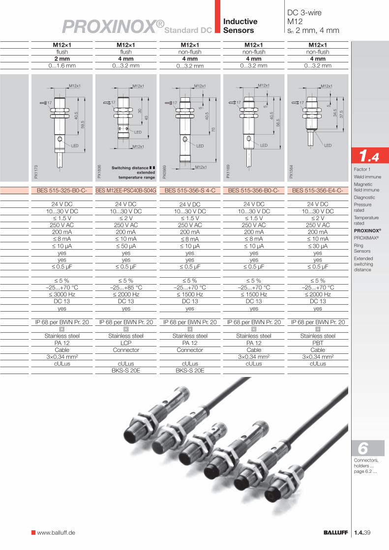
BES 515-325-S 4-C
24 V DC10...30 V DC
≤ 1.5 V250 V AC200 mA≤ 8 mA≤ 10 µA
yesyes
≤ 0.5 µF
≤ 5 %–25...+70 °C≤ 3000 Hz
DC 13yes
IP 68 per BWN Pr. 20
Stainless steelPA 12
Connector
cULusBKS-S 20E
1.4.38
InductiveSensors
DC 3-wireM8, M12sn 1.5 mm, 2 mm
Housing sizeMounting (see notes starting p. 1.0.11)Rated operating distance sn
Assured operating distance sa
NO
Rated operational voltage Ue
Supply voltage UB
Voltage drop Ud at IeRated insulation voltage Ui
Rated operational current IeNo-load supply current I0 max.Off-state current IrPolarity reversal protectedShort circuit protectedPermissible load capacitance
Repeat accuracy RAmbient temperature range Ta
Frequency of operating cycles fUtilization categoryFunction indicator
Degree of protection per IEC 60529Insulation classHousing materialMaterial of sensing faceConnectionNo. of wires × cross-sectionApprovalRecommended connector
Takes it all –Stainless steel housingstop aggressive mediacold.
Inductive proximity switchesare used increasingly inaggressive surroundings.
This applies especially to theworking zone of machinetools or in the chemicalindustry, on packagingmachines and in the foodindustry. The main elementsat work are aggressivecleaning agents combinedwith high-pressure cleaningequipment.
Wiring diagrams see page 1.0.6Switching distance see page 1.0.10
For sensors with cable please append cablematerial and length to ordering code!PVC, standard length 3 m = 03PUR, standard length 3 m= PU-03
PNP
M8×1flush
1.5 mm0...1.2 mm
BES 515-324-E5-C-S 49
24 V DC10...30 V DC
≤ 1.5 V75 V DC200 mA≤ 10 mA≤ 80 µA
yesyes
≤ 1 µF
≤ 5 %–25...+70 °C≤ 1000 Hz
DC 13yes
IP 67
Stainless steel 1.4571PA 12
Connector
cULusBKS-S 49E
The solution = PROXINOX®
stainless
steel
1.4.39
InductiveSensors
DC 3-wireM12sn 2 mm, 4 mm
M12×1flush
2 mm0...1.6 mm
BES 515-325-B0-C-
24 V DC10...30 V DC
≤ 1.5 V250 V AC200 mA≤ 8 mA≤ 10 µA
yesyes
≤ 0.5 µF
≤ 5 %–25...+70 °C≤ 3000 Hz
DC 13yes
IP 68 per BWN Pr. 20
Stainless steelPA 12Cable
3×0.34 mm²cULus
M12×1non-flush
4 mm0...3.2 mm
BES 515-356-B0-C-
24 V DC10...30 V DC
≤ 1.5 V250 V AC200 mA≤ 8 mA≤ 10 µA
yesyes
≤ 0.5 µF
≤ 5 %–25...+70 °C≤ 1500 Hz
DC 13yes
IP 68 per BWN Pr. 20
Stainless steelPA 12Cable
3×0.34 mm²cULus
M12×1non-flush
4 mm0...3.2 mm
BES 515-356-S 4-C
24 V DC10...30 V DC
≤ 1.5 V250 V AC200 mA≤ 8 mA≤ 10 µA
yesyes
≤ 0.5 µF
≤ 5 %–25...+70 °C≤ 1500 Hz
DC 13yes
IP 68 per BWN Pr. 20
Stainless steelPA 12
Connector
cULusBKS-S 20E
M12×1non-flush
4 mm0...3.2 mm
BES 515-356-E4-C-
24 V DC10...30 V DC
≤ 2 V250 V AC200 mA≤ 10 mA≤ 30 µA
yesyes
≤ 0.5 µF
≤ 5 %–25...+70 °C≤ 2000 Hz
DC 13yes
IP 68 per BWN Pr. 20
Stainless steelPBT
Cable3×0.34 mm²
cULus
Standard DCPROXINOX®
Connectors,holders ...page 6.2 ...
6
1.4
M12×1flush
4 mm0...3.2 mm
BES M12EE-PSC40B-S04G
24 V DC10...30 V DC
≤ 2 V250 V AC200 mA≤ 10 mA≤ 50 µA
yesyes
≤ 0.5 µF
≤ 5 %–25...+85 °C≤ 2000 Hz
DC 13yes
IP 68 per BWN Pr. 20
Stainless steelLCP
Connector
cULusBKS-S 20E
Switching distance extended
temperature range
Factor 1
Weld immune
Magneticfield immune
Diagnostic
Pressurerated
Temperaturerated
PROXINOX®
PROXIMAX®
RingSensors
Extendedswitchingdistance
17
5
34.5
37.5
PX1
564
LED
M12x1
www.balluff.de

InductiveSensors
DC 3-/4-wireM18sn 5 mm, 8 mm
Wiring diagrams see page 1.0.6
For sensors with cable please append cablematerial and length to ordering code!PVC, standard length 3 m = 03PUR, standard length 3 m = PU-03
Housing sizeMounting (see notes starting p. 1.0.11)Rated operating distance sn
Assured operating distance sa
NO
complementary
Rated operational voltage Ue
Supply voltage UB
Voltage drop Ud at IeRated insulation voltage Ui
Rated operational current IeNo-load supply current I0 max.Off-state current IrPolarity reversal protectedShort circuit protectedPermissible load capacitance
Repeat accuracy RAmbient temperature range Ta
Frequency of operating cycles fUtilization categoryFunction indicator
Degree of protection per IEC 60529Insulation classHousing materialMaterial of sensing faceConnectionNo. of wires × cross-sectionApprovalRecommended connector
PNP
M18×1flush
5 mm0...4.1 mm
BES 515-326-B0-C-
24 V DC10...30 V DC
≤ 1.5 V250 V AC200 mA≤ 12 mA≤ 10 µA
yesyes
≤ 0.8 µF
≤ 5 %–25...+70 °C
900 HzDC 13
yes
IP 68 per BWN Pr. 20
Stainless steelPA 12Kabel
3×0.34 mm²cULus
M18×1flush
5 mm0...4.1 mm
BES 515-326-S 4-C
24 V DC10...30 V DC
≤ 1.5 V250 V AC200 mA≤ 12 mA≤ 10 µA
yesyes
≤ 0.8 µF
≤ 5 %–40...+85 °C
900 HzDC 13
yes
IP 68 per BWN Pr. 20
Stainless steelPA 12
Connector
cULusBKS-S 20E
M18×1non-flush
8 mm0...6.5 mm
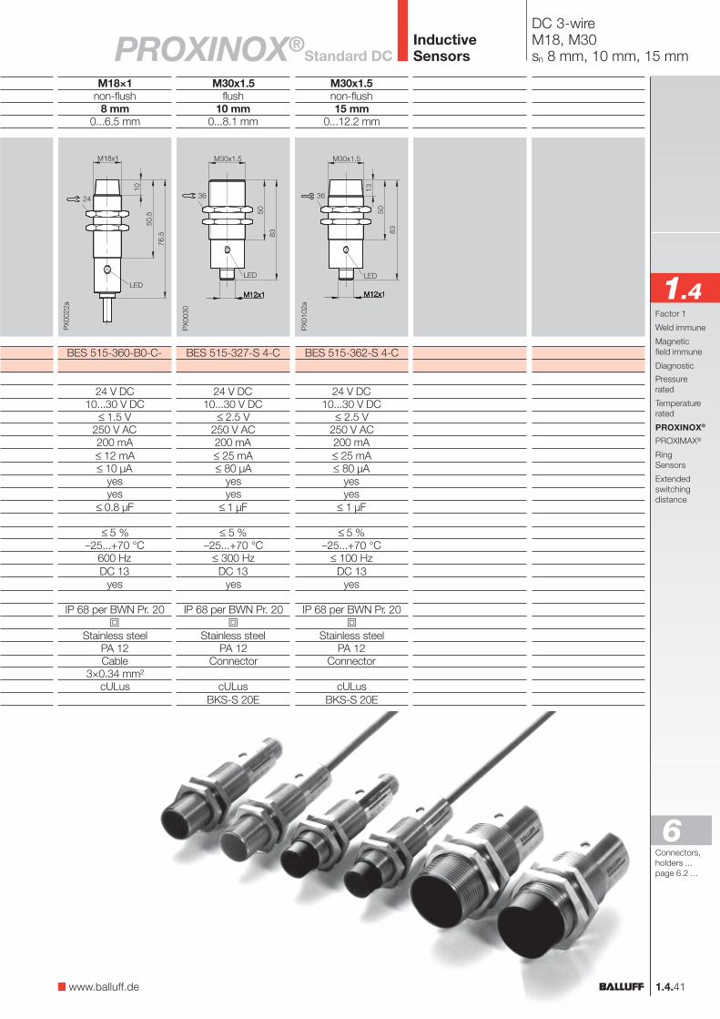
BES 515-360-S 4-C
24 V DC10...30 V DC
≤ 1.5 V250 V AC200 mA≤ 12 mA≤ 10 µA
yesyes
≤ 0.8 µF
≤ 5 %–40...+85 °C
600 HzDC 13
yes
IP 68 per BWN Pr. 20
Stainless steelPA 12
Connector
cULusBKS-S 20E
1.4.40
extendedtemperature range
extendedtemperature range
M18×1non-flush
8 mm0...6.5 mm
BES 515-123-S 4-C
24 V DC10...30 V DC
≤ 2.5 V250 V AC200 mA≤ 30 mA≤ 80 µA
yesyes
≤ 1 µF
≤ 5 %–40...+85 °C
200 HzDC 13
yes
IP 68 per BWN Pr. 20
Stainless steelPA 12
Connector
cULusBKS-S 20E
extendedtemperature range
stainless
steel
InductiveSensors
DC 3-wireM18, M30sn 8 mm, 10 mm, 15 mm
M30x1.5flush
10 mm0...8.1 mm
BES 515-327-S 4-C
24 V DC10...30 V DC
≤ 2.5 V250 V AC200 mA≤ 25 mA≤ 80 µA
yesyes
≤ 1 µF
≤ 5 %–25...+70 °C
≤ 300 HzDC 13
yes
IP 68 per BWN Pr. 20
Stainless steelPA 12
Connector
cULusBKS-S 20E
M30x1.5non-flush15 mm
0...12.2 mm
BES 515-362-S 4-C
24 V DC10...30 V DC
≤ 2.5 V250 V AC200 mA≤ 25 mA≤ 80 µA
yesyes
≤ 1 µF
≤ 5 %–25...+70 °C
≤ 100 HzDC 13
yes
IP 68 per BWN Pr. 20
Stainless steelPA 12
Connector
cULusBKS-S 20E
1.4.41
PROXINOX®
Connectors,holders ...page 6.2 ...
6
M18×1non-flush
8 mm0...6.5 mm
BES 515-360-B0-C-
24 V DC10...30 V DC
≤ 1.5 V250 V AC200 mA≤ 12 mA≤ 10 µA
yesyes
≤ 0.8 µF
≤ 5 %–25...+70 °C
600 HzDC 13
yes
IP 68 per BWN Pr. 20
Stainless steelPA 12Cable
3×0.34 mm²cULus
1.4Factor 1
Weld immune
Magneticfield immune
Diagnostic
Pressurerated
Temperaturerated
PROXINOX®
PROXIMAX®
RingSensors
Extendedswitchingdistance
www.balluff.de
Standard DC
1.4.42
InductiveSensors PROXINOX® Sensors
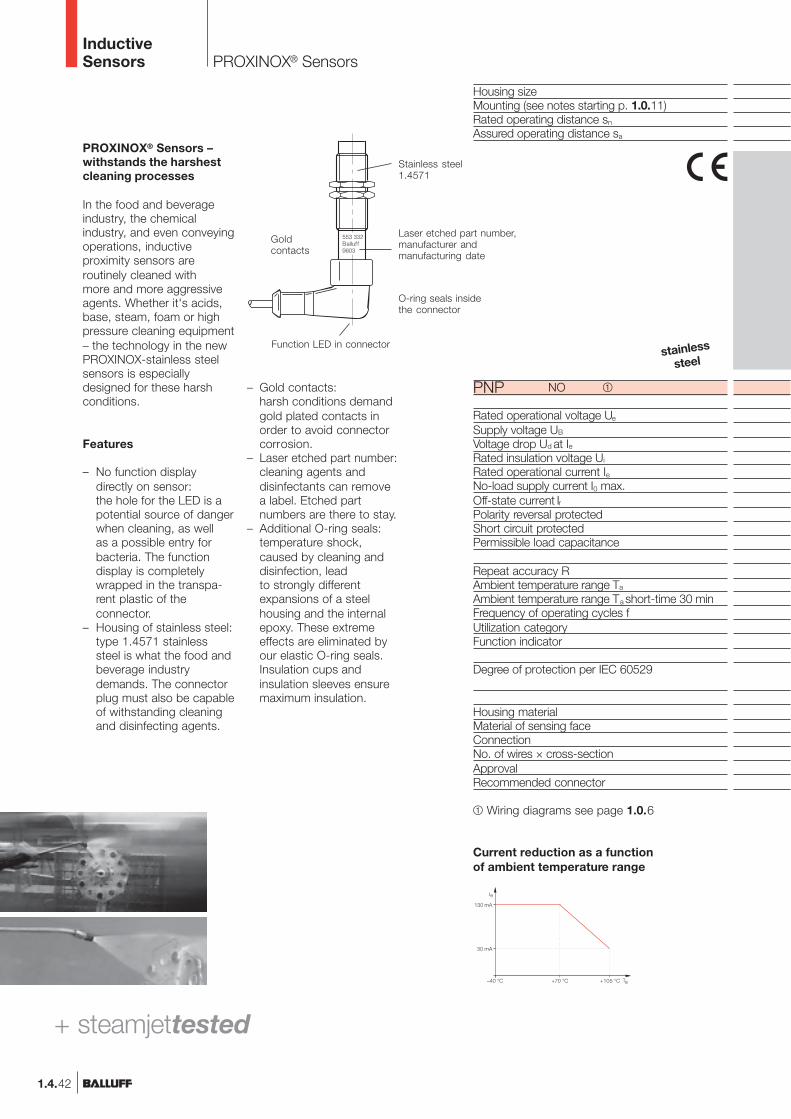
PROXINOX® Sensors –withstands the harshestcleaning processes
In the food and beverageindustry, the chemicalindustry, and even conveyingoperations, inductiveproximity sensors areroutinely cleaned withmore and more aggressiveagents. Whether it's acids,base, steam, foam or highpressure cleaning equipment– the technology in the newPROXINOX-stainless steelsensors is especiallydesigned for these harshconditions.
Features
– No function displaydirectly on sensor:the hole for the LED is apotential source of dangerwhen cleaning, as wellas a possible entry forbacteria. The functiondisplay is completelywrapped in the transpa-rent plastic of theconnector.
– Housing of stainless steel:type 1.4571 stainlesssteel is what the food andbeverage industrydemands. The connectorplug must also be capableof withstanding cleaningand disinfecting agents.
– Gold contacts:harsh conditions demandgold plated contacts inorder to avoid connectorcorrosion.
– Laser etched part number:cleaning agents anddisinfectants can removea label. Etched partnumbers are there to stay.
– Additional O-ring seals:temperature shock,caused by cleaning anddisinfection, leadto strongly differentexpansions of a steelhousing and the internalepoxy. These extremeeffects are eliminated byour elastic O-ring seals.Insulation cups andinsulation sleeves ensuremaximum insulation.
Housing sizeMounting (see notes starting p. 1.0.11)Rated operating distance sn
Assured operating distance sa
NO
Rated operational voltage Ue
Supply voltage UB
Voltage drop Ud at IeRated insulation voltage Ui
Rated operational current IeNo-load supply current I0 max.Off-state current IrPolarity reversal protectedShort circuit protectedPermissible load capacitance
Repeat accuracy RAmbient temperature range Ta
Ambient temperature range Ta short-time 30 minFrequency of operating cycles fUtilization categoryFunction indicator
Degree of protection per IEC 60529
Housing materialMaterial of sensing faceConnectionNo. of wires × cross-sectionApprovalRecommended connector
Wiring diagrams see page 1.0.6
PNP
Current reduction as a functionof ambient temperature range
–40 °C +105 °C+70 °C
130 mA
30 mA
Stainless steel1.4571
Laser etched part number,manufacturer andmanufacturing date
Function LED in connector
Goldcontacts
O-ring seals insidethe connector
+ steamjettested
stainless
steel
1.4.43
InductiveSensors
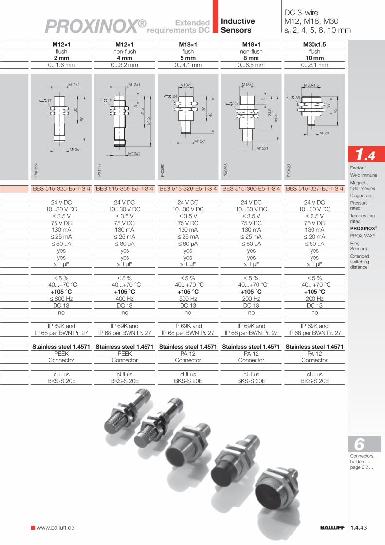
DC 3-wireM12, M18, M30sn 2, 4, 5, 8, 10 mm
M12×1flush
2 mm0...1.6 mm
BES 515-325-E5-T-S 4
24 V DC10...30 V DC
≤ 3.5 V75 V DC130 mA≤ 25 mA≤ 80 µA
yesyes
≤ 1 µF
≤ 5 %–40...+70 °C
+105 °C≤ 800 HzDC 13
no
IP 69K andIP 68 per BWN Pr. 27
Stainless steel 1.4571PEEK
Connector
cULusBKS-S 20E
M12×1non-flush
4 mm0...3.2 mm
BES 515-356-E5-T-S 4
24 V DC10...30 V DC
≤ 3.5 V75 V DC130 mA≤ 25 mA≤ 80 µA
yesyes
≤ 1 µF
≤ 5 %–40...+70 °C
+105 °C400 HzDC 13
no
IP 69K andIP 68 per BWN Pr. 27
Stainless steel 1.4571PEEK
Connector
cULusBKS-S 20E
Extendedrequirements DCPROXINOX®
Connectors,holders ...page 6.2 ...
6
M18×1flush
5 mm0...4.1 mm
BES 515-326-E5-T-S 4
24 V DC10...30 V DC
≤ 3.5 V75 V DC130 mA≤ 25 mA≤ 80 µA
yesyes
≤ 1 µF
≤ 5 %–40...+70 °C
+105 °C500 HzDC 13
no
IP 69K andIP 68 per BWN Pr. 27
Stainless steel 1.4571PA 12
Connector
cULusBKS-S 20E
M18×1non-flush
8 mm0...6.5 mm
BES 515-360-E5-T-S 4
24 V DC10...30 V DC
≤ 3.5 V75 V DC130 mA≤ 25 mA≤ 80 µA
yesyes
≤ 1 µF
≤ 5 %–40...+70 °C
+105 °C200 HzDC 13
no
IP 69K andIP 68 per BWN Pr. 27
Stainless steel 1.4571PA 12
Connector
cULusBKS-S 20E
M30x1.5flush
10 mm0...8.1 mm
BES 515-327-E5-T-S 4
24 V DC10...30 V DC
≤ 3.5 V75 V DC130 mA≤ 20 mA≤ 80 µA
yesyes
≤ 1 µF
≤ 5 %–40...+70 °C
+105 °C200 HzDC 13
no
IP 69K andIP 68 per BWN Pr. 27
Stainless steel 1.4571PA 12
Connector
cULusBKS-S 20E
1.4Factor 1
Weld immune
Magneticfield immune
Diagnostic
Pressurerated
Temperaturerated
PROXINOX®
PROXIMAX®
RingSensors
Extendedswitchingdistance
www.balluff.de
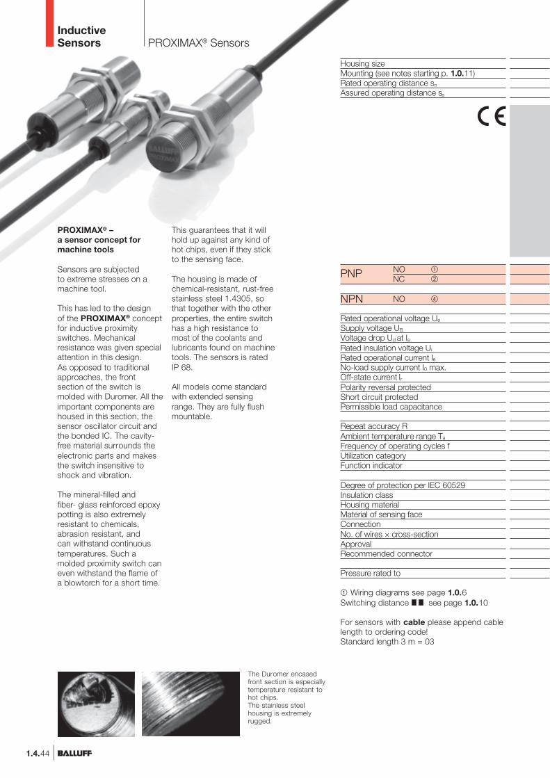
The Duromer encasedfront section is especiallytemperature resistant tohot chips.The stainless steelhousing is extremelyrugged.
InductiveSensors PROXIMAX® Sensors
1.4.44
Housing sizeMounting (see notes starting p. 1.0.11)Rated operating distance sn
Assured operating distance sa
NO
NC
NO
Rated operational voltage Ue
Supply voltage UB
Voltage drop Ud at IeRated insulation voltage Ui
Rated operational current IeNo-load supply current I0 max.Off-state current IrPolarity reversal protectedShort circuit protectedPermissible load capacitance
Repeat accuracy RAmbient temperature range Ta
Frequency of operating cycles fUtilization categoryFunction indicator
Degree of protection per IEC 60529Insulation classHousing materialMaterial of sensing faceConnectionNo. of wires × cross-sectionApprovalRecommended connector
Pressure rated to
PROXIMAX® –a sensor concept formachine tools
Sensors are subjectedto extreme stresses on amachine tool.
This has led to the designof the PROXIMAX® conceptfor inductive proximityswitches. Mechanicalresistance was given specialattention in this design.As opposed to traditionalapproaches, the frontsection of the switch ismolded with Duromer. All theimportant components arehoused in this section, thesensor oscillator circuit andthe bonded IC. The cavity-free material surrounds theelectronic parts and makesthe switch insensitive toshock and vibration.
The mineral-filled andfiber- glass reinforced epoxypotting is also extremelyresistant to chemicals,abrasion resistant, andcan withstand continuoustemperatures. Such amolded proximity switch caneven withstand the flame ofa blowtorch for a short time.
This guarantees that it willhold up against any kind ofhot chips, even if they stickto the sensing face.
The housing is made ofchemical-resistant, rust-freestainless steel 1.4305, sothat together with the otherproperties, the entire switchhas a high resistance tomost of the coolants andlubricants found on machinetools. The sensors is ratedIP 68.
All models come standardwith extended sensingrange. They are fully flushmountable.
Wiring diagrams see page 1.0.6Switching distance see page 1.0.10
For sensors with cable please append cablelength to ordering code!Standard length 3 m = 03
PNP
NPN

InductiveSensors
DC 3-wireM12, M18sn 4 mm, 8 mm
1.4.45
M12×1flush
4 mm0...3.2 mm
BES M12EL-PSC40B-BP_ _
24 V DC10...30 V DC
≤ 1.8 V250 V AC200 mA≤ 8 mA≤ 10 µA
yesyes
≤ 1 µF
≤ 5 %–40...+85 °C
1000 HzDC 13
yes
IP 68 per BWN Pr. 20
Stainless steelEP (Duromer)Cable, PUR3×0.34 mm²
cULus
60 bar
M12×1flush
4 mm0...3.2 mm
BES M12EL-PSC40B-S04GBES M12EL-POC40B-S04G
BES M12EL-NSC40B-S04G
24 V DC10...30 V DC
≤ 1.8 V250 V AC200 mA≤ 8 mA≤ 10 µA
yesyes
≤ 1 µF
≤ 5 %–40...+105 °C
1000 HzDC 13
yes
IP 68 per BWN Pr. 20
Stainless steelEP (Duromer)Connector
cULusBKS-S 23/BKS-S 24
60 bar
PROXIMAX®
M18×1flush
8 mm0...6.5 mm
BES M18EL-PSC80B-BP_ _
24 V DC10...30 V DC
≤ 1.8 V250 V AC200 mA≤ 8 mA≤ 10 µA
yesyes
≤ 1 µF
≤ 5 %–40...+85 °C
700 HzDC 13
yes
IP 68 per BWN Pr. 20
Stainless steelEP (Duromer)Cable, PUR3×0.34 mm²
cULus
60 bar
M18×1flush
8 mm0...6.5 mm
BES M18EL-PSC80B-S04GBES M18EL-POC80B-S04G
BES M18EL-NSC80B-S04G
24 V DC10...30 V DC
≤ 1.8 V250 V AC200 mA≤ 8 mA≤ 10 µA
yesyes
≤ 1 µF
≤ 5 %–40...+105 °C
700 HzDC 13
yes
IP 68 per BWN Pr. 20
Stainless steelEP (Duromer)Connector
cULusBKS-S 23/BKS-S 24
60 bar
Connectors,holders ...page 6.2 ...
Switching distance temperature rated
Switching distance
6
1.4Factor 1
Weld immune
Magneticfield immune
Diagnostic
Pressurerated
Temperaturerated
PROXINOX®
PROXIMAX®
RingSensors
Extendedswitchingdistance
Switching distance temperature rated
Switching distance
www.balluff.de