Embed Size (px)
Citation preview

Course in ANSYS
Modeling reviewed – Boolean’s
Computational Mechanics, AAU, EsbjergANSYS
Course Outline
IntroductionIntroductionLesson 1. Modeling reviewed – Boolean’sLesson 2. Boolean’s + meshing issuesLesson 3. Operate + meshing issuesLesson 4. Import + meshing issuesLesson 5. Meshing – advanced topics
Lesson 1 – Part 2 2Computational Mechanics, AAU, EsbjergANSYS

Citation of the day
“ Finite Element Analysis makes a goodengineer great, and a bad engineer dangerous !”
Robert D. Cook,Professor of Mechanical Engineering,University of Wisconsin, Madison
Lesson 1 – Part 2 3Computational Mechanics, AAU, EsbjergANSYS

ModelingProgramme for Lesson: BUILD THE MODEL
• Modeling considerations• Element Type• Real Constants• Material Properties• Sections• Geometry/Modeling
– WorkPlane & Coordinate systems– Keypoints– Lines– Areas– Volumes
• MeshingLesson 1 – Part 2 4
Computational Mechanics, AAU, EsbjergANSYS

Modeling considerations• As you begin your model generation, you will (consciously or
unconsciously) make a number of decisions that determine how youwill mathematically simulate the physical system:– What are the objectives of your analysis?– Will you need to vary/modify model data?– Will you need to change the geometric topology of the model, e.g. add
holes to the model?– Will you model all, or just a portion, of the physical system? – How much detail will you include in your model? – What kinds of elements will you use? How dense should your finite
element mesh be? • In general, you will attempt to balance computational expense (CPU
time, etc.) against precision of results as you answer these questions.
• The decisions you make in the planning stage of your analysis will largely govern the success or failure of your analysis efforts.
Lesson 1 – Part 2 5Computational Mechanics, AAU, EsbjergANSYS

Modeling considerations• Linear or Higher Order Elements• Take Advantage of Symmetry
– The axis of symmetry must coincide with the global Cartesian Y-axis.– Negative nodal X-coordinates are not permitted.– The global Cartesian Y-direction represents the axial direction, the
global Cartesian X-direction represents the radial direction, and the global Cartesian Z-direction corresponds to the circumferential direction.
– Your model should be assembled using appropriate element types: • For axisymmetric models, use applicable 2-D solids with KEYOPT(3) = 1,
and/or axisymmetric shells. In addition, various link, contact, combination, and surface elements can be included in a model that also contains axisymmetric solids or shells. (The program will not realize that these "other" elements are axisymmetric unless axisymmetric solids or shells are present.)
• How Much Detail to Include• Appropriate Mesh Density
Lesson 1 – Part 2 6Computational Mechanics, AAU, EsbjergANSYS

Lesson 1 – Part 2 7Computational Mechanics, AAU, EsbjergANSYS
Modeling considerations
Real modelContinuum
Analysis modelDiscrete
Each point have aninfinite number ofdeformation statevariables, i.e. degre-es of freedom (dof)
Each point have afinitefinite number ofdeformation statevariables (u,v), i.e. degrees of freedom
Transformation

Modeling considerations
Lesson 1 – Part 2 8Computational Mechanics, AAU, EsbjergANSYS
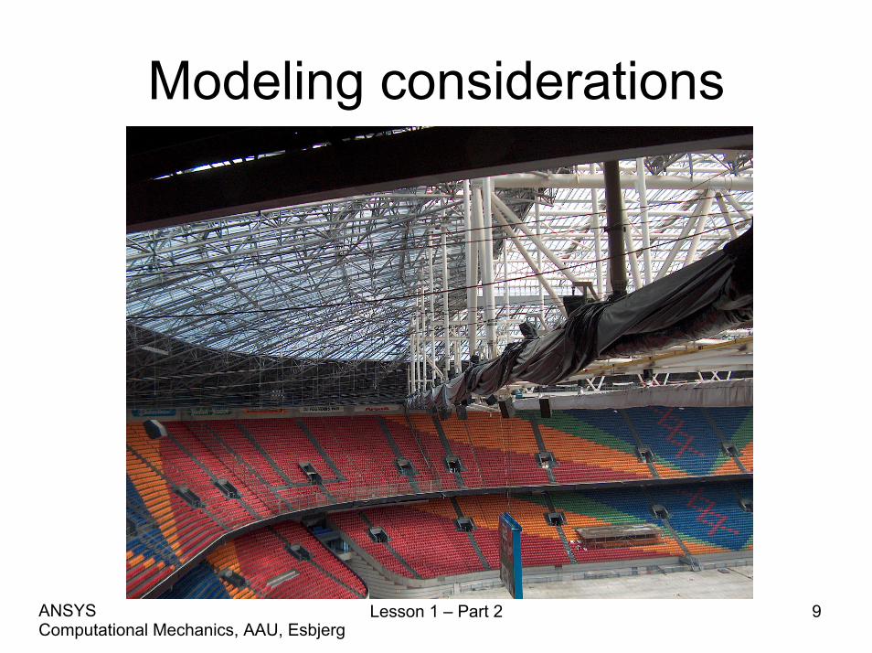
Modeling considerations
Lesson 1 – Part 2 9Computational Mechanics, AAU, EsbjergANSYS
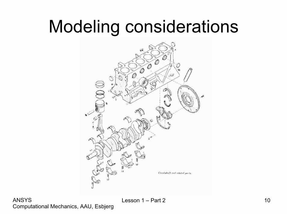
Modeling considerations
Lesson 1 – Part 2 10Computational Mechanics, AAU, EsbjergANSYS

Modeling considerationsWHEEL LOADER REALIZATION- a model and an architecture thatenables simulation in a process context
By Ulf Sellgren
ISRN KTH/MMK/R—03/07—SETRITA-MMK 2003:07ISSN 1400-1179
Lesson 1 – Part 2 11Computational Mechanics, AAU, EsbjergANSYS

Modeling considerations
Lesson 1 – Part 2 12Computational Mechanics, AAU, EsbjergANSYS

Modeling considerations
Lesson 1 – Part 2 13Computational Mechanics, AAU, EsbjergANSYS

Modeling considerations
Lesson 1 – Part 2 14Computational Mechanics, AAU, EsbjergANSYS

Modeling considerations
• Characterization of problem
Lesson 1 – Part 2 15Computational Mechanics, AAU, EsbjergANSYS
Rod Beam
Disk Plate
Shell Solid

Modeling considerations
• The ANSYS program does not assume a system of units for your analysis.
• Units must however be consistent for all input data.
Lesson 1 – Part 2 16Computational Mechanics, AAU, EsbjergANSYS
Geometry/Modelling
• Creating a solid model within ANSYS.• Using direct generation.• Importing a model created in a computer-
aided design (CAD) system.
Lesson 1 – Part 2 17Computational Mechanics, AAU, EsbjergANSYS
Coordinate systems• Global and local coordinate systems are used to locate geometry
items (nodes, keypoints, etc.) in space.• The display coordinate system determines the system in which
geometry items are listed or displayed.• The nodal coordinate system defines the degree of freedom
directions at each node and the orientation of nodal results data.• The element coordinate system determines the orientation of
material properties and element results data.• The results coordinate system is used to transform nodal or element
results data to a particular coordinate system for listings, displays, or general postprocessing operations (POST1).
• The working plane, which is separate from the coordinate systemsdiscussed in this chapter, is used to locate geometric primitives during the modeling process.
Lesson 1 – Part 2 18Computational Mechanics, AAU, EsbjergANSYS

Coordinate systems
• (a) Cartesian (X, Y, Z components) coordinate system 0 (C.S.0)
• (b) Cylindrical (R, θ, Z components) coordinate system 1 (C.S.1)
• (c) Spherical (R, θ, φ components) coordinate system 2 (C.S.2)
• (d) Cylindrical (R, θ, Y components) coordinate system 5 (C.S.5)
Lesson 1 – Part 2 19Computational Mechanics, AAU, EsbjergANSYS
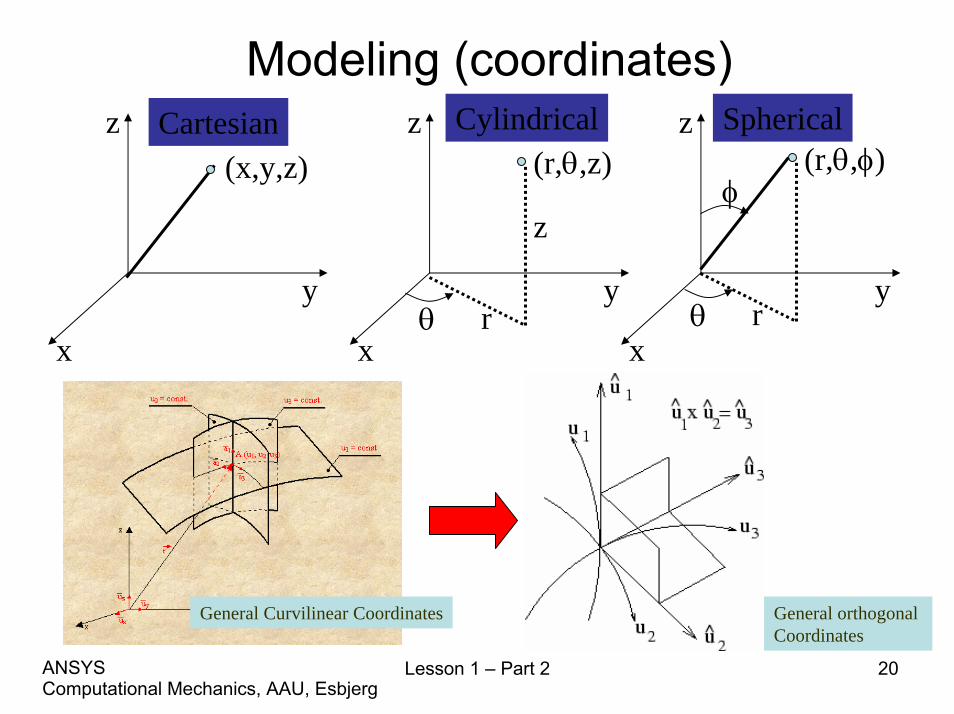
Modeling (coordinates)
x
y
z
x
y
z
x
y
z(r,θ,z)
z
rθ
(r,θ,φ)
rθ
φ(x,y,z)
Cartesian Cylindrical Spherical
General Curvilinear Coordinates General orthogonal Coordinates
Lesson 1 – Part 2 20Computational Mechanics, AAU, EsbjergANSYS
Lesson 1 – Part 2 21Computational Mechanics, AAU, EsbjergANSYS
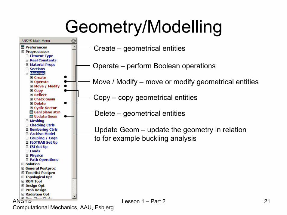
Geometry/ModellingCreate – geometrical entities
Operate – perform Boolean operations
Move / Modify – move or modify geometrical entities
Copy – copy geometrical entities
Delete – geometrical entities
Update Geom – update the geometry in relationto for example buckling analysis
Lesson 1 – Part 2 22Computational Mechanics, AAU, EsbjergANSYS
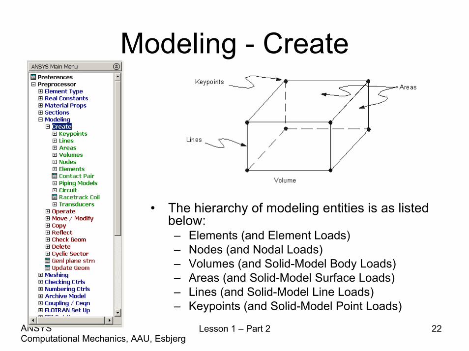
Modeling - Create
• The hierarchy of modeling entities is as listed below:– Elements (and Element Loads)– Nodes (and Nodal Loads)– Volumes (and Solid-Model Body Loads)– Areas (and Solid-Model Surface Loads)– Lines (and Solid-Model Line Loads)– Keypoints (and Solid-Model Point Loads)
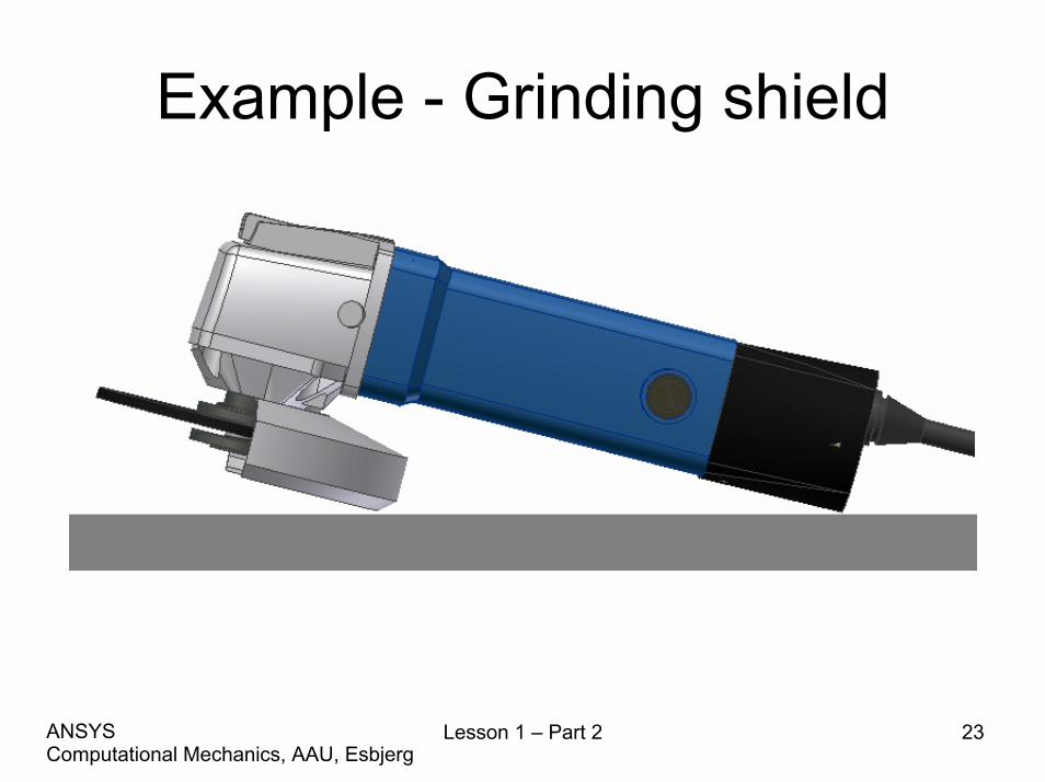
Example - Grinding shield
Lesson 1 – Part 2 23Computational Mechanics, AAU, EsbjergANSYS
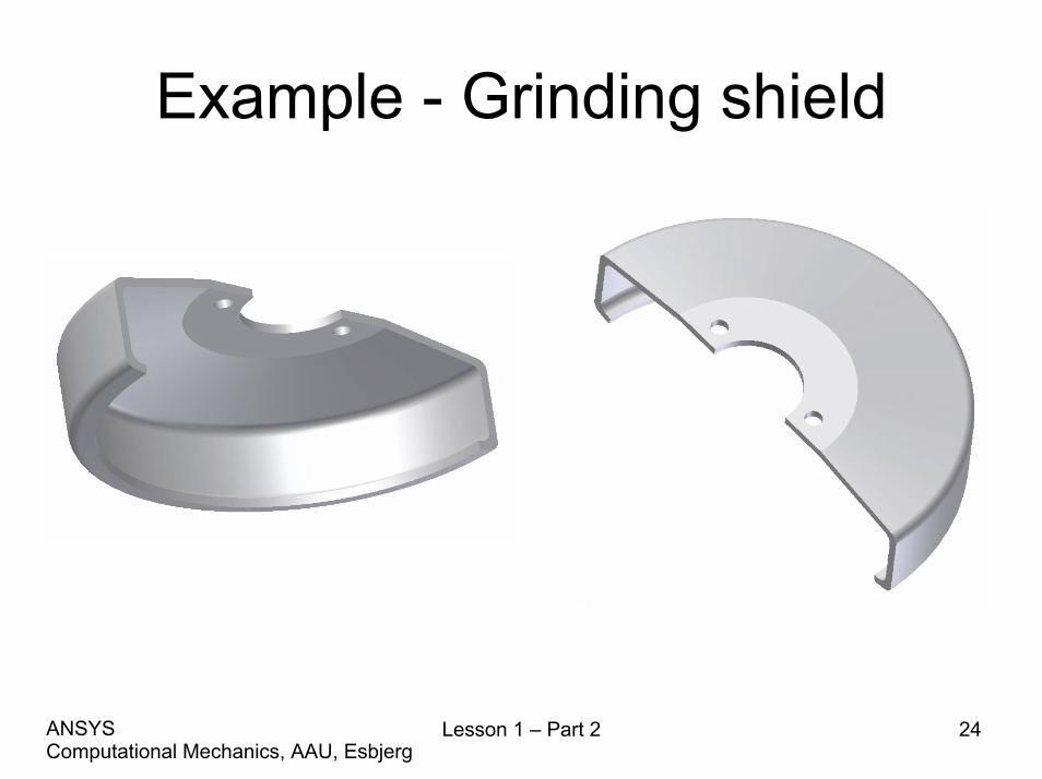
Example - Grinding shield
Lesson 1 – Part 2 24Computational Mechanics, AAU, EsbjergANSYS
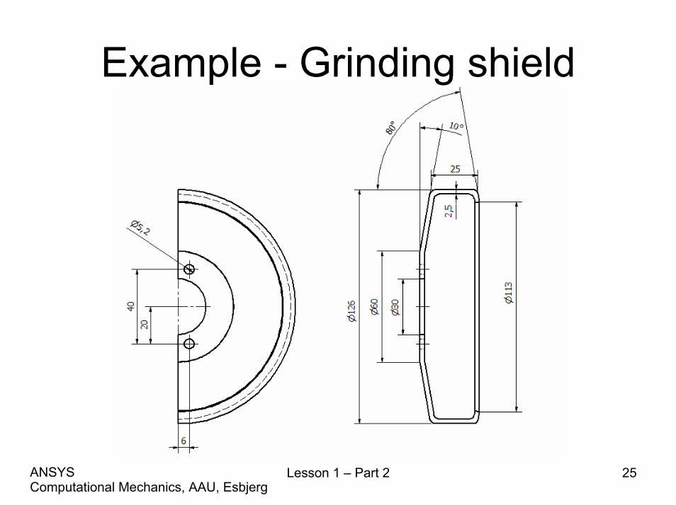
Example - Grinding shield
Lesson 1 – Part 2 25Computational Mechanics, AAU, EsbjergANSYS

Example - Grinding shieldModeling considerations
• Model storage *.lgw or *.db?• Element type?• Level of detail?• Mesh method?• Allow model modifications?• Type of analysis to perform?• Material models?• Boundary conditions and loads?
Lesson 1 – Part 2 26Computational Mechanics, AAU, EsbjergANSYS
Example - Grinding shieldModeling considerations
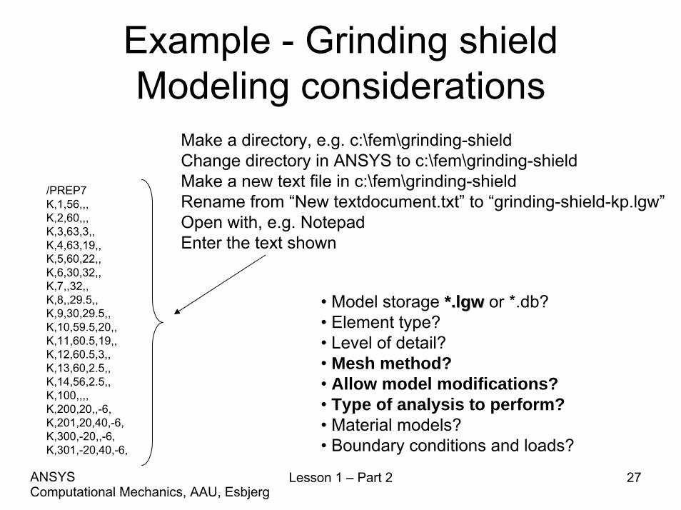
/PREP7 K,1,56,,, K,2,60,,, K,3,63,3,,K,4,63,19,, K,5,60,22,, K,6,30,32,, K,7,,32,, K,8,,29.5,, K,9,30,29.5,, K,10,59.5,20,, K,11,60.5,19,, K,12,60.5,3,,K,13,60,2.5,, K,14,56,2.5,, K,100,,,, K,200,20,,-6, K,201,20,40,-6, K,300,-20,,-6, K,301,-20,40,-6,
• Model storage *.*.lgwlgw or *.db?• Element type?• Level of detail?• Mesh method?• Allow model modifications?• Type of analysis to perform?• Material models?• Boundary conditions and loads?
Make a directory, e.g. c:\fem\grinding-shieldChange directory in ANSYS to c:\fem\grinding-shieldMake a new text file in c:\fem\grinding-shieldRename from “New textdocument.txt” to “grinding-shield-kp.lgw”Open with, e.g. NotepadEnter the text shown
Lesson 1 – Part 2 27Computational Mechanics, AAU, EsbjergANSYS

Example - Grinding shieldModeling considerations
/PREP7 LSTR, 1, 2 LSTR, 3, 4 LSTR, 5, 6 LSTR, 6, 7 LSTR, 7, 8 LSTR, 8, 9 LSTR, 9, 10 LSTR, 11, 12 LSTR, 13, 14 LSTR, 14, 1 !* L2TAN,1,2 !* L2TAN,-9,-8 !* L2TAN,2,3 !* L2TAN,-8,-7 LSTR, 9, 6 LSTR, 5, 10 LSTR, 4, 11 LSTR, 3, 12 LSTR, 2, 13
• Model storage *.*.lgwlgw or *.db?• Element type?• Level of detail?• Mesh method?• Allow model modifications?• Type of analysis to perform?• Material models?• Boundary conditions and loads?
Make a new text file in c:\fem\grinding-shieldRename from “New textdocument.txt” to “grinding-shield-lines.lgw”Open with, e.g. NotepadEnter the text shown
Lesson 1 – Part 2 28Computational Mechanics, AAU, EsbjergANSYS

Example - Grinding shieldModeling considerations
/PREP7 AL,4,5,6,15 AL,15,16,3,7 AL,16,13,17,14 AL,17,2,18,8 AL,18,12,19,11 AL,19,10,9,1 !*CIRCLE,100,15,7, , , AL,20,21,22,23 !*CIRCLE,200,3,201, , , AL,24,25,26,27 !*CIRCLE,300,3,301, , , AL,28,29,30,31
• Model storage *.*.lgwlgw or *.db?• Element type?• Level of detail?• Mesh method?• Allow model modifications?• Type of analysis to perform?• Material models?• Boundary conditions and loads?
Make a new text file in c:\fem\grinding-shieldRename from “New textdocument.txt” to “grinding-shield-areas.lgw”Open with, e.g. NotepadEnter the text shown
A GOOD TIME TO SAVE AS *.dbA GOOD TIME TO SAVE AS *.db
Lesson 1 – Part 2 29Computational Mechanics, AAU, EsbjergANSYS

Modeling - Operate
Perform geometrical operations in order to obtain new geometrical entities
Lesson 1 – Part 2 30Computational Mechanics, AAU, EsbjergANSYS

Example - Grinding shieldModeling considerations
Enter the command sequence in the command line
\PREP7VROTAT,1,2,3,4,5,6,8,7,180, ,
A GOOD TIME TO SAVE AS *.dbA GOOD TIME TO SAVE AS *.db
• Model storage *.*.lgwlgw or *.db?• Element type?• Level of detail?• Mesh method?• Allow model modifications?• Type of analysis to perform?• Material models?• Boundary conditions and loads?
Lesson 1 – Part 2 31Computational Mechanics, AAU, EsbjergANSYS

Example - Grinding shieldModeling considerations
Enter the command sequence in the command line
\PREP7VOFFST,7,40,VOFFST,8,40,VOFFST,9,40, A GOOD TIME TO SAVE AS *.dbA GOOD TIME TO SAVE AS *.db
• Model storage *.*.lgwlgw or *.db?• Element type?• Level of detail?• Mesh method?• Allow model modifications?• Type of analysis to perform?• Material models?• Boundary conditions and loads?
Lesson 1 – Part 2 32Computational Mechanics, AAU, EsbjergANSYS
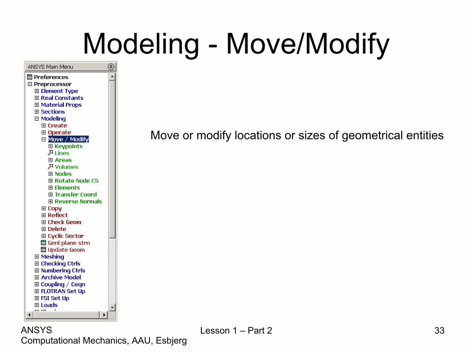
Modeling - Move/Modify
Move or modify locations or sizes of geometrical entities
Lesson 1 – Part 2 33Computational Mechanics, AAU, EsbjergANSYS
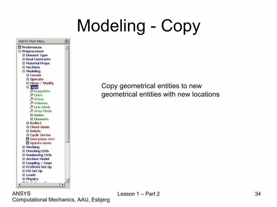
Modeling - Copy
Copy geometrical entities to new geometrical entities with new locations
Lesson 1 – Part 2 34Computational Mechanics, AAU, EsbjergANSYS

Lesson 1 – Part 2 35Computational Mechanics, AAU, EsbjergANSYS
Modeling - Delete
• The hierarchy of modeling entities is as listed below:– Elements (and Element Loads)– Nodes (and Nodal Loads)– Volumes (and Solid-Model Body Loads)– Areas (and Solid-Model Surface Loads)– Lines (and Solid-Model Line Loads)– Keypoints (and Solid-Model Point Loads)
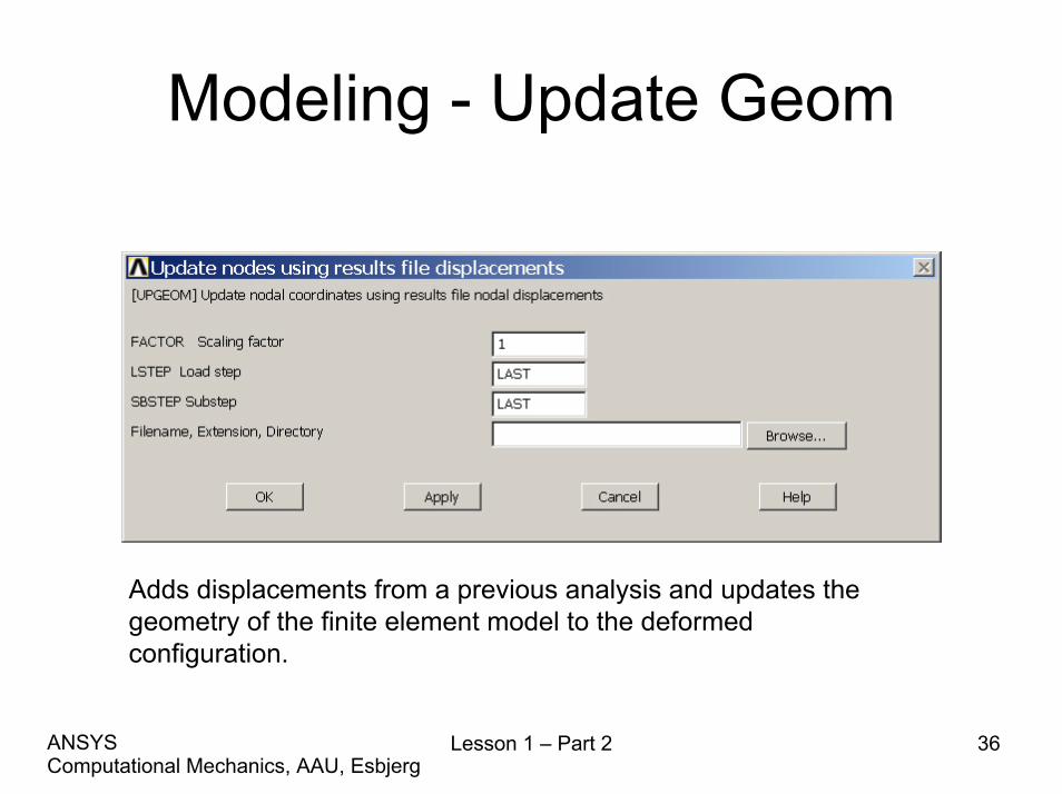
Modeling - Update Geom
Adds displacements from a previous analysis and updates the geometry of the finite element model to the deformed configuration.
Lesson 1 – Part 2 36Computational Mechanics, AAU, EsbjergANSYS

Booleans - Intersect
LINL (Line Intersect Line) AINA (Area Intersect Area)
Lesson 1 – Part 2 37Computational Mechanics, AAU, EsbjergANSYS
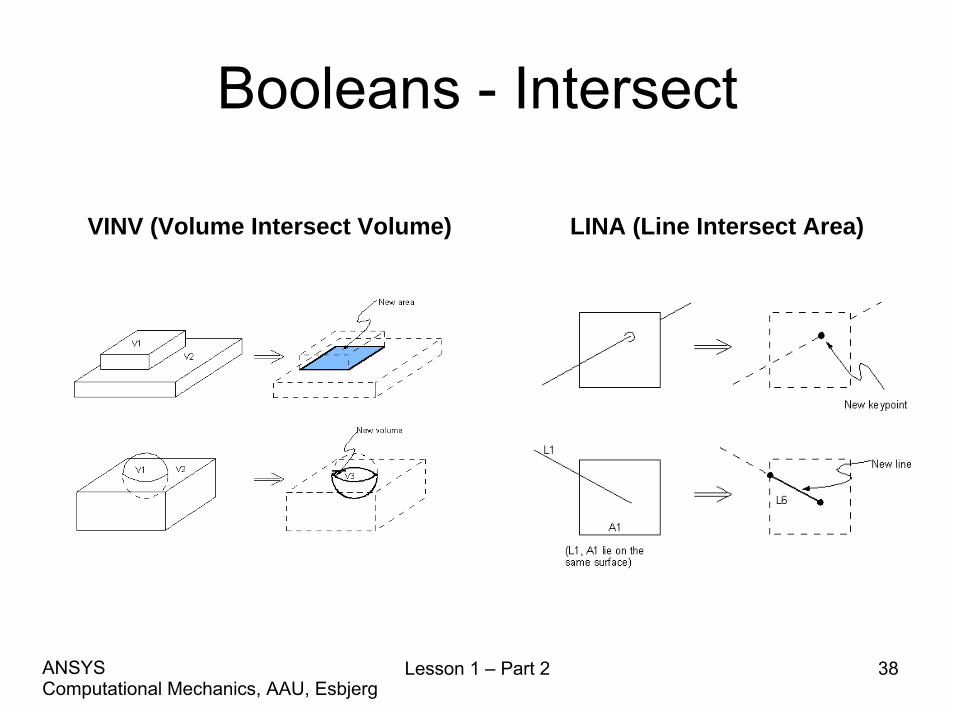
Booleans - Intersect
VINV (Volume Intersect Volume) LINA (Line Intersect Area)
Lesson 1 – Part 2 38Computational Mechanics, AAU, EsbjergANSYS
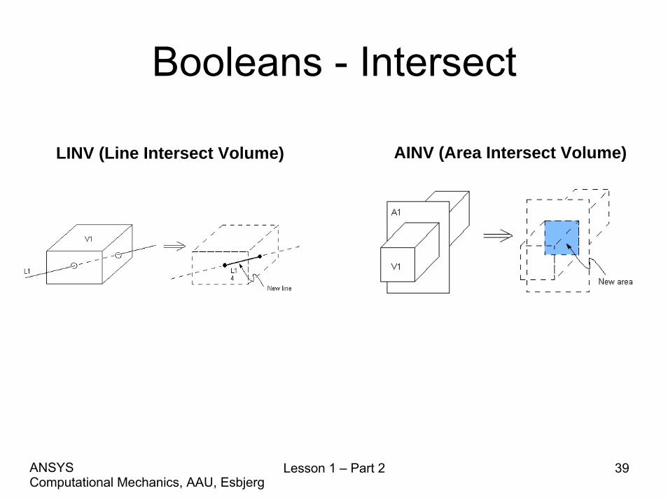
Booleans - Intersect
AINV (Area Intersect Volume)LINV (Line Intersect Volume)
Lesson 1 – Part 2 39Computational Mechanics, AAU, EsbjergANSYS

Booleans - Add
AADD (Add Areas) VADD (Add Volumes)
Lesson 1 – Part 2 40Computational Mechanics, AAU, EsbjergANSYS
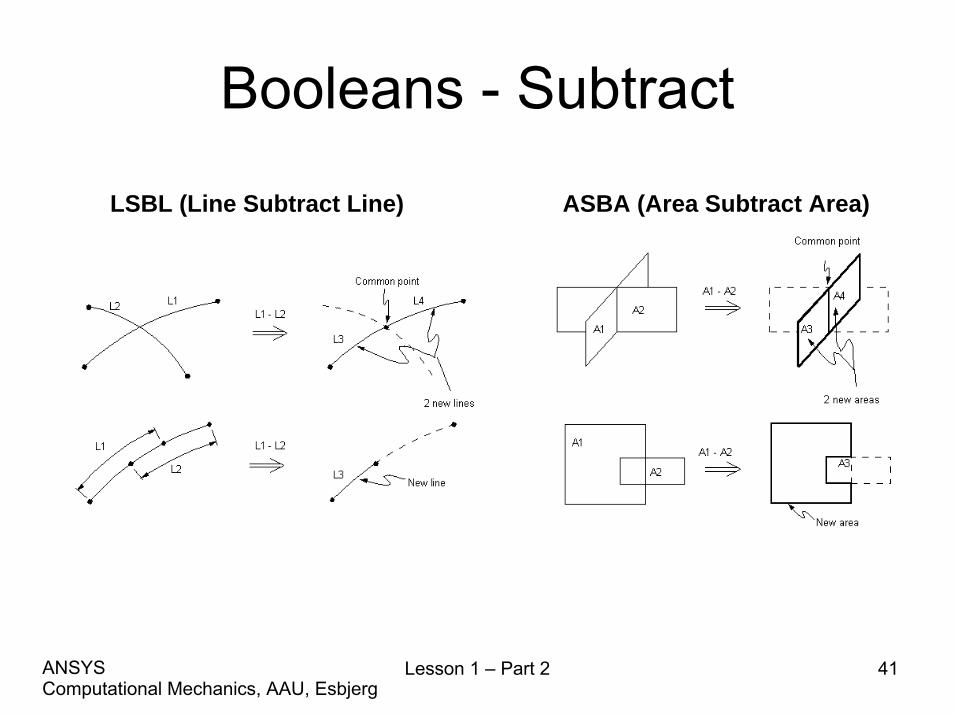
Booleans - Subtract
LSBL (Line Subtract Line) ASBA (Area Subtract Area)
Lesson 1 – Part 2 41Computational Mechanics, AAU, EsbjergANSYS
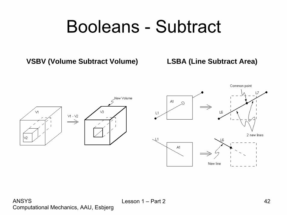
Booleans - Subtract
VSBV (Volume Subtract Volume) LSBA (Line Subtract Area)
Lesson 1 – Part 2 42Computational Mechanics, AAU, EsbjergANSYS

Example - Grinding shieldModeling considerations
• Model storage *.*.lgwlgw or *.db?• Element type?• Level of detail?• Mesh method?• Allow model modifications?• Type of analysis to perform?• Material models?• Boundary conditions and loads?
Enter the command sequence in the command line
\PREP7VSBV,ALL, 13 !*VSBV,ALL, 14 !*VSBV,ALL, 15
Lesson 1 – Part 2 43Computational Mechanics, AAU, EsbjergANSYS
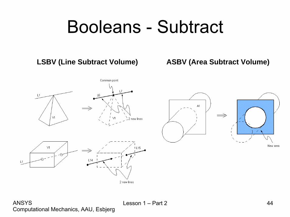
Booleans - Subtract
LSBV (Line Subtract Volume) ASBV (Area Subtract Volume)
Lesson 1 – Part 2 44Computational Mechanics, AAU, EsbjergANSYS

Booleans - Subtract
ASBL (Area Subtract Line) VSBA (Volume Subtract Area)
Lesson 1 – Part 2 45Computational Mechanics, AAU, EsbjergANSYS

Booleans - OverlapLOVLAP (Line Overlap Line) AOVLAP (Area Overlap Area)
VOVLAP (Volume Overlap Volume)
Lesson 1 – Part 2 46Computational Mechanics, AAU, EsbjergANSYS
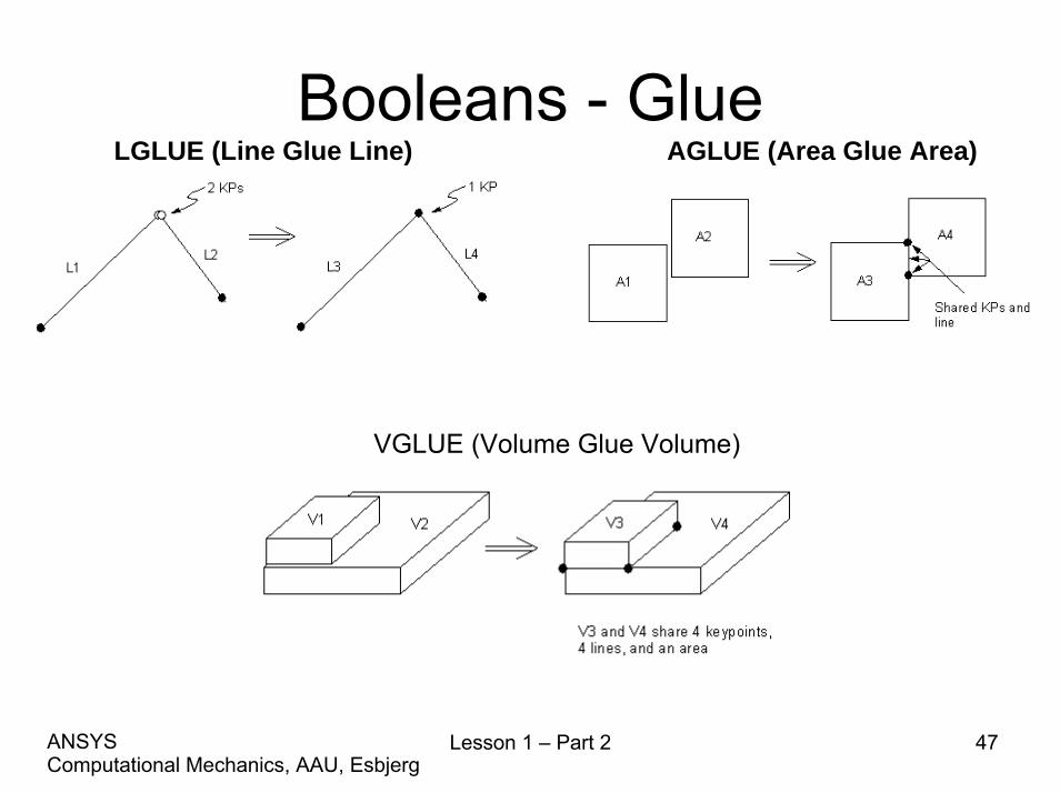
Booleans - GlueAGLUE (Area Glue Area)LGLUE (Line Glue Line)
VGLUE (Volume Glue Volume)
Lesson 1 – Part 2 47Computational Mechanics, AAU, EsbjergANSYS


![Ansys Kurulumu - bim.yildiz.edu.tr · Documentation Only' Install MPI for ANSYS ... ANSYS ANSYS F ANSYS ANSYS AIM (V] ANSYS AP-SYS CFO [V) ANSYS ore S . msys Realize Product Promise"](https://img.dokumen.tips/doc/110x75/5b69d01e7f8b9a422e8b4fb9/ansys-kurulumu-bim-documentation-only-install-mpi-for-ansys-ansys-ansys.jpg)