Embed Size (px)
Citation preview

FleetLINK® Fuel Control System System2TM for FleetLINK Operator’s Manual
©2002 OPW Fuel Management Systems Manual No. M41-21.03L

OPW Fuel Management Systems - System and Replacement Parts Warranty Statement Effective September 1, 2002 System and Replacement Parts Warranty OPW Fuel Management Systems warrants that all OPW Tank Gauge and Petro Vend Fuel Control systems supplied by OPW Fuel Management Systems to the Original Purchaser will be free from defects in material and/or workmanship under normal use and service for a period of 12 months from the date of installation or 15 months from the date of shipment. Additionally, OPW Fuel Management Systems warrants that all upgrades and replacement parts (new and remanufactured) supplied by OPW Fuel Management Systems will be free from defects in material and workmanship under normal use and service for a period of 90 days from the date of installation or for the remainder of the system’s original warranty, whichever is greater, as set forth in the first sentence of this statement. The foregoing warranties will not extend to goods subjected to misuse, neglect, accident, or improper installation or maintenance or which have been altered or repaired by anyone other than OPW Fuel Management Systems or its authorized representative. The buyer’s acceptance of delivery of the goods constitutes acceptance of the foregoing warranties and remedies, and all conditions and limitations thereof. If a claim is made within the warranted time period that any equipment and/or remanufactured part is defective in material or workmanship under normal use and service, such equipment and/or remanufactured part shall be returned to OPW Fuel Management Systems, freight prepaid. If such equipment or remanufactured part is found by OPW Fuel Management Systems in its sole judgment, to be defective in material or workmanship under normal use and service, OPW Fuel Management Systems, shall, at its sole option, repair or replace such equipment and/or remanufactured part (excluding, in all instances, fuses, ink cartridges, batteries, other consumable items, etc.) The warranties, as set forth above, are made expressly in lieu of all other warranties, either expressed or implied, including, without limitation, warranties of merchantability and fitness for any particular purpose and of all other obligations or liabilities on OPW Fuel Management Systems part. Further, OPW Fuel Management Systems neither assumes, nor authorizes any other person to assume for it, any other liability in connection with the sale of the systems, or any new/replacement part that has been subject to any damage from any act of nature or any force majeure. The term “Original Purchaser” as used in these warranties shall be deemed to mean the authorized OPW Fuel Management Systems distributor to which the system or any new/replacement part was originally sold. These warranties may be assigned by the original purchaser to any of its customers who purchase any OPW Fuel Management Systems systems or new/replacement parts. The sole liability of OPW Fuel Management Systems, for any breach of warranty, shall be as set forth above. OPW Fuel Management Systems does not warrant against damage caused by accident, abuse, faulty or improper installation or operation. In no event shall manufacturer’s liability on any claim for damages arising out of the manufacture, sale, delivery or use of the goods exceed the original purchase price of the goods. In no event shall OPW Fuel Management Systems be liable for any direct, indirect, incidental or consequential damage or loss of product.

i
Table Of Contents
Part I - Introduction
1.0 Features . . . . . . . . . . . . . . . . . . . . . . . . . . . . . . . . . . . . . . . . . . . . . . . . . . . . . . . . . . . . . . . . . . 1
2.0 Equipment Overview . . . . . . . . . . . . . . . . . . . . . . . . . . . . . . . . . . . . . . . . . . . . . . . . . . . . . . 22.1 Fuel Island Terminal (FIT) . . . . . . . . . . . . . . . . . . . . . . . . . . . . . . . . . . . . . . . . . . . . . . . . . 2
2.1.1 Installation . . . . . . . . . . . . . . . . . . . . . . . . . . . . . . . . . . . . . . . . . . . . . . . . . . . . . 22.1.2 Card or Key Readers . . . . . . . . . . . . . . . . . . . . . . . . . . . . . . . . . . . . . . . . . . . . . 22.1.3 Display . . . . . . . . . . . . . . . . . . . . . . . . . . . . . . . . . . . . . . . . . . . . . . . . . . . . . . . . 22.1.4 Printer Option . . . . . . . . . . . . . . . . . . . . . . . . . . . . . . . . . . . . . . . . . . . . . . . . . . . 32.1.5 Keypad Operation . . . . . . . . . . . . . . . . . . . . . . . . . . . . . . . . . . . . . . . . . . . . . . . 32.1.6 FIT Specifications . . . . . . . . . . . . . . . . . . . . . . . . . . . . . . . . . . . . . . . . . . . . . . . 3
2.2 Outdoor Payment Terminal (OPT) . . . . . . . . . . . . . . . . . . . . . . . . . . . . . . . . . . . . . . . . . . . 42.3 Pump Control Terminal (PCT) . . . . . . . . . . . . . . . . . . . . . . . . . . . . . . . . . . . . . . . . . . . . . . 52.4 Fuel Site Controller (FSC) . . . . . . . . . . . . . . . . . . . . . . . . . . . . . . . . . . . . . . . . . . . . . . . . . 7
2.4.1 Installation Overview . . . . . . . . . . . . . . . . . . . . . . . . . . . . . . . . . . . . . . . . . . . . . 72.4.2 External Computer Connections . . . . . . . . . . . . . . . . . . . . . . . . . . . . . . . . . . . . . 72.4.3 Journal Printer . . . . . . . . . . . . . . . . . . . . . . . . . . . . . . . . . . . . . . . . . . . . . . . . . . 72.4.4 Modem Use . . . . . . . . . . . . . . . . . . . . . . . . . . . . . . . . . . . . . . . . . . . . . . . . . . . . 82.4.5 Battery Backup . . . . . . . . . . . . . . . . . . . . . . . . . . . . . . . . . . . . . . . . . . . . . . . . . . 82.4.6 STATUS LED . . . . . . . . . . . . . . . . . . . . . . . . . . . . . . . . . . . . . . . . . . . . . . . . . . . 82.4.7 FSC Specifications . . . . . . . . . . . . . . . . . . . . . . . . . . . . . . . . . . . . . . . . . . . . . . . 8
3.0 Operational Overview . . . . . . . . . . . . . . . . . . . . . . . . . . . . . . . . . . . . . . . . . . . . . . . . . . . . . 93.1 MAIN MENU . . . . . . . . . . . . . . . . . . . . . . . . . . . . . . . . . . . . . . . . . . . . . . . . . . . . . . . . . . . 93.2 SYSTEM ACCESS MENU . . . . . . . . . . . . . . . . . . . . . . . . . . . . . . . . . . . . . . . . . . . . . . . . . 93.3 SYSTEM TIMES MENU . . . . . . . . . . . . . . . . . . . . . . . . . . . . . . . . . . . . . . . . . . . . . . . . . 103.4 SYSTEM DEVICES MENU . . . . . . . . . . . . . . . . . . . . . . . . . . . . . . . . . . . . . . . . . . . . . . . 10
3.4.1 FIT Programming Overview . . . . . . . . . . . . . . . . . . . . . . . . . . . . . . . . . . . . . . . 103.4.2 PCT Programming Overview . . . . . . . . . . . . . . . . . . . . . . . . . . . . . . . . . . . . . . 113.4.3 UPC Programming Overview . . . . . . . . . . . . . . . . . . . . . . . . . . . . . . . . . . . . . . 11
3.5 CUSTOMER MESSAGES MENU . . . . . . . . . . . . . . . . . . . . . . . . . . . . . . . . . . . . . . . . . . 113.6 SYSTEM PARAMETERS MENU . . . . . . . . . . . . . . . . . . . . . . . . . . . . . . . . . . . . . . . . . . . 113.7 RESTRICTIONS MENU . . . . . . . . . . . . . . . . . . . . . . . . . . . . . . . . . . . . . . . . . . . . . . . . . 113.8 CARDS/ACCOUNTS MENU . . . . . . . . . . . . . . . . . . . . . . . . . . . . . . . . . . . . . . . . . . . . . . 113.9 TRANSACTION DATA MENU . . . . . . . . . . . . . . . . . . . . . . . . . . . . . . . . . . . . . . . . . . . . . 123.10 SYSTEM TOTALS MENU . . . . . . . . . . . . . . . . . . . . . . . . . . . . . . . . . . . . . . . . . . . . . . . 123.11 JOURNAL PRINTER MENU . . . . . . . . . . . . . . . . . . . . . . . . . . . . . . . . . . . . . . . . . . . . . 12
4.0 Practice Session . . . . . . . . . . . . . . . . . . . . . . . . . . . . . . . . . . . . . . . . . . . . . . . . . . . . . . . . . 154.1 SESSION OVERVIEW . . . . . . . . . . . . . . . . . . . . . . . . . . . . . . . . . . . . . . . . . . . . . . . . . . 154.2 STEP-BY-STEP PROCEDURE . . . . . . . . . . . . . . . . . . . . . . . . . . . . . . . . . . . . . . . . . . . . 15
4.2.1 Terminal Connection . . . . . . . . . . . . . . . . . . . . . . . . . . . . . . . . . . . . . . . . . . . . 154.2.2 Should You Use the Menus . . . . . . . . . . . . . . . . . . . . . . . . . . . . . . . . . . . . . . . 164.2.3 Set the Time and Date . . . . . . . . . . . . . . . . . . . . . . . . . . . . . . . . . . . . . . . . . . . 164.2.4 How Much Memory in the System? . . . . . . . . . . . . . . . . . . . . . . . . . . . . . . . . . 164.2.5 What Kind Of Fuel? . . . . . . . . . . . . . . . . . . . . . . . . . . . . . . . . . . . . . . . . . . . . . 174.2.6 What Kind Of Tank? . . . . . . . . . . . . . . . . . . . . . . . . . . . . . . . . . . . . . . . . . . . . 174.2.7 Introduce Yourself to the Customer . . . . . . . . . . . . . . . . . . . . . . . . . . . . . . . . . . 184.2.8 Tell The System About Your
Transaction Records . . . . . . . . . . . . . . . . . . . . . . . . 194.2.9 How Many Cards? What Should
They Say? . . . . . . . . . . . . . . . . . . . . . . . . . . . . . . . . . . . . . . . . . . . . . . . . . . . 19
SYSTEM2 Operator's Guide
ii 10/15/97
4.2.10 Configure and Install a PCTPosition . . . . . . . . . . . . . . . . . . . . . . . . . . . . . . . . . . . . . . . . . . . . . . . . . . . . . 20
4.2.11 Configure & Install a FIT . . . . . . . . . . . . . . . . . . . . . . . . . . . . . . . . . . . . . . . . . 214.2.12 Create a Sample Card File &
Account . . . . . . . . . . . . . . . . . . . . . . . . . . . . . . . . . . . . . . . . . . . . . . . . . . . . . 224.2.13 Download Your Program . . . . . . . . . . . . . . . . . . . . . . . . . . . . . . . . . . . . . . . . . 244.2.14 Try a Transaction . . . . . . . . . . . . . . . . . . . . . . . . . . . . . . . . . . . . . . . . . . . . . . 24
Part II - Programming . . . . . . . . . . . . . . . . . . . . . . . . . . . . . . . . . . . . . . . . . . . . . . . . . . . . . . . . . 25
5.0 Menu Overview . . . . . . . . . . . . . . . . . . . . . . . . . . . . . . . . . . . . . . . . . . . . . . . . . . . . . . . . . . . 255.1 USING THE MENUS . . . . . . . . . . . . . . . . . . . . . . . . . . . . . . . . . . . . . . . . . . . . . . . . . . . . 255.2 COMMANDS & OPTIONS . . . . . . . . . . . . . . . . . . . . . . . . . . . . . . . . . . . . . . . . . . . . . . . . 265.3 HELP SCREENS . . . . . . . . . . . . . . . . . . . . . . . . . . . . . . . . . . . . . . . . . . . . . . . . . . . . . . . 26
6.0 System Access Menu . . . . . . . . . . . . . . . . . . . . . . . . . . . . . . . . . . . . . . . . . . . . . . . . . . . . . 276.1 OPEN/CLOSE . . . . . . . . . . . . . . . . . . . . . . . . . . . . . . . . . . . . . . . . . . . . . . . . . . . . . . . . . 276.2 HELLO/BYE . . . . . . . . . . . . . . . . . . . . . . . . . . . . . . . . . . . . . . . . . . . . . . . . . . . . . . . . . . . 276.3 CALL . . . . . . . . . . . . . . . . . . . . . . . . . . . . . . . . . . . . . . . . . . . . . . . . . . . . . . . . . . . . . . . . 286.4 PASSTHRU . . . . . . . . . . . . . . . . . . . . . . . . . . . . . . . . . . . . . . . . . . . . . . . . . . . . . . . . . . . 28
7.0 System Times Menu . . . . . . . . . . . . . . . . . . . . . . . . . . . . . . . . . . . . . . . . . . . . . . . . . . . . . . 297.1 TIME . . . . . . . . . . . . . . . . . . . . . . . . . . . . . . . . . . . . . . . . . . . . . . . . . . . . . . . . . . . . . . . . 297.2 TIME CHANGE . . . . . . . . . . . . . . . . . . . . . . . . . . . . . . . . . . . . . . . . . . . . . . . . . . . . . . . . 297.3 DATE . . . . . . . . . . . . . . . . . . . . . . . . . . . . . . . . . . . . . . . . . . . . . . . . . . . . . . . . . . . . . . . . 307.4 SYSTEM ON TIME . . . . . . . . . . . . . . . . . . . . . . . . . . . . . . . . . . . . . . . . . . . . . . . . . . . . . 307.5 LIGHT ON TIME . . . . . . . . . . . . . . . . . . . . . . . . . . . . . . . . . . . . . . . . . . . . . . . . . . . . . . . 30
8.0 System Devices Menu . . . . . . . . . . . . . . . . . . . . . . . . . . . . . . . . . . . . . . . . . . . . . . . . . . . . 318.1 FIT # . . . . . . . . . . . . . . . . . . . . . . . . . . . . . . . . . . . . . . . . . . . . . . . . . . . . . . . . . . . . . . . . 31
8.1.1 Show FIT # . . . . . . . . . . . . . . . . . . . . . . . . . . . . . . . . . . . . . . . . . . . . . . . . . . . . 318.1.2 Configure FIT # . . . . . . . . . . . . . . . . . . . . . . . . . . . . . . . . . . . . . . . . . . . . . . . . 328.1.3 Install FIT . . . . . . . . . . . . . . . . . . . . . . . . . . . . . . . . . . . . . . . . . . . . . . . . . . . . . 328.1.4 Remove FIT . . . . . . . . . . . . . . . . . . . . . . . . . . . . . . . . . . . . . . . . . . . . . . . . . . . 32
8.2 OPT # . . . . . . . . . . . . . . . . . . . . . . . . . . . . . . . . . . . . . . . . . . . . . . . . . . . . . . . . . 33 Show OPT # . . . . . . . . . . . . . . . . . . . . . . . . . . . . . . . . . . . . . . . . . . . . . . . . . . . . . . . 338.2.2 Configure OPT # . . . . . . . . . . . . . . . . . . . . . . . . . . . . . . . . . . . . . . . . . . . . . . . 338.2.3 Install OPT . . . . . . . . . . . . . . . . . . . . . . . . . . . . . . . . . . . . . . . . . . . . . . . . . . . 338.2.4 Remove OPT . . . . . . . . . . . . . . . . . . . . . . . . . . . . . . . . . . . . . . . . . . . . . . . . . . 33
8.3 PCT # . . . . . . . . . . . . . . . . . . . . . . . . . . . . . . . . . . . . . . . . . . . . . . . . . . . . . . . . . . . . . . . 348.3.1 Configure PCT # . . . . . . . . . . . . . . . . . . . . . . . . . . . . . . . . . . . . . . . . . . . . . . . . 348.3.3 Remove PCT # . . . . . . . . . . . . . . . . . . . . . . . . . . . . . . . . . . . . . . . . . . . . . . . . 34
8.4 PCT #/POSITION # . . . . . . . . . . . . . . . . . . . . . . . . . . . . . . . . . . . . . . . . . . . . . . . . . . . . . 348.4.1 Configure PCT #/Position # . . . . . . . . . . . . . . . . . . . . . . . . . . . . . . . . . . . . . . . 358.4.2 Install or Remove PCT/ Position # . . . . . . . . . . . . . . . . . . . . . . . . . . . . . . . . . . 36
8.5 PUMP # . . . . . . . . . . . . . . . . . . . . . . . . . . . . . . . . . . . . . . . . . . . . . . . . . . . . . . . . . . . . . . 368.6 PROGRAM . . . . . . . . . . . . . . . . . . . . . . . . . . . . . . . . . . . . . . . . . . . . . . . . . . . . . . . . . . . 368.7 SET PUMP ON . . . . . . . . . . . . . . . . . . . . . . . . . . . . . . . . . . . . . . . . . . . . . . . . . . . . . . . . 368.8 DOWNLOAD . . . . . . . . . . . . . . . . . . . . . . . . . . . . . . . . . . . . . . . . . . . . . . . . . . . . . . . . . . 368.9 DOWNLOAD FIT #/OPT#/PCT # . . . . . . . . . . . . . . . . . . . . . . . . . . . . . . . . . . . . . . . . . . . 36
System2 for FleetLINK Table Of Contents
iii
9.0 Customer Messages Menu . . . . . . . . . . . . . . . . . . . . . . . . . . . . . . . . . . . . . . . . . . . . . . . 379.1 WHAT'S A RECEIPT? . . . . . . . . . . . . . . . . . . . . . . . . . . . . . . . . . . . . . . . . . . . . . . . . . . . 379.2 RECEIPT BODY . . . . . . . . . . . . . . . . . . . . . . . . . . . . . . . . . . . . . . . . . . . . . . . . . . . . . . . 389.3 RECEIPT HEADER . . . . . . . . . . . . . . . . . . . . . . . . . . . . . . . . . . . . . . . . . . . . . . . . . . . . . 389.4 RECEIPT TRAILER . . . . . . . . . . . . . . . . . . . . . . . . . . . . . . . . . . . . . . . . . . . . . . . . . . . . . 399.5 RECEIPT BONUS POINTS . . . . . . . . . . . . . . . . . . . . . . . . . . . . . . . . . . . . . . . . . . . . . . . 399.6 SAMPLE RECEIPTS . . . . . . . . . . . . . . . . . . . . . . . . . . . . . . . . . . . . . . . . . . . . . . . . . . . . 399.7 DISPLAY (#...) . . . . . . . . . . . . . . . . . . . . . . . . . . . . . . . . . . . . . . . . . . . . . . . . . . . . . . . . . 41
9.7.1 Display Type Overview . . . . . . . . . . . . . . . . . . . . . . . . . . . . . . . . . . . . . . . . . . 419.7.2 Dual Languages . . . . . . . . . . . . . . . . . . . . . . . . . . . . . . . . . . . . . . . . . . . . . . . . 419.7.3 Special Characters . . . . . . . . . . . . . . . . . . . . . . . . . . . . . . . . . . . . . . . . . . . . . . 419.7.4 Format Display Default . . . . . . . . . . . . . . . . . . . . . . . . . . . . . . . . . . . . . . . . . . 419.7.5 Default FIT or OPT Prompts . . . . . . . . . . . . . . . . . . . . . . . . . . . . . . . . . . . . . . 429.7.6 Standard 2 x 16 Display . . . . . . . . . . . . . . . . . . . . . . . . . . . . . . . . . . . . . . . . . . 439.7.7 1 x 40 Display (Optional) . . . . . . . . . . . . . . . . . . . . . . . . . . . . . . . . . . . . . . . . . 439.7.8 Graphics Display (Optional) . . . . . . . . . . . . . . . . . . . . . . . . . . . . . . . . . . . . . 43
9.8 KEYBOARD (#...) . . . . . . . . . . . . . . . . . . . . . . . . . . . . . . . . . . . . . . . . . . . . . . . . . . . . . . 579.9 MESSAGING . . . . . . . . . . . . . . . . . . . . . . . . . . . . . . . . . . . . . . . . . . . . . . . . . . . . . . . . . 57
9.9.1 Overview . . . . . . . . . . . . . . . . . . . . . . . . . . . . . . . . . . . . . . . . . . . . . . . . . . . . . 579.9.2 Procedure . . . . . . . . . . . . . . . . . . . . . . . . . . . . . . . . . . . . . . . . . . . . . . . . . . . . 57
9.10 DATE . . . . . . . . . . . . . . . . . . . . . . . . . . . . . . . . . . . . . . . . . . . . . . . . . . . . . . . . . . . . . . 599.10.1 Procedure . . . . . . . . . . . . . . . . . . . . . . . . . . . . . . . . . . . . . . . . . . . . . . . . . . . 599.10.2 Month Labeling . . . . . . . . . . . . . . . . . . . . . . . . . . . . . . . . . . . . . . . . . . . . . . . . 599.10.3 Date Order . . . . . . . . . . . . . . . . . . . . . . . . . . . . . . . . . . . . . . . . . . . . . . . . . . . 599.10.4 Date Separators . . . . . . . . . . . . . . . . . . . . . . . . . . . . . . . . . . . . . . . . . . . . . . . 59
10.0 System Parameters Menu . . . . . . . . . . . . . . . . . . . . . . . . . . . . . . . . . . . . . . . . . . . . . . . 6110.1 SYSTEM . . . . . . . . . . . . . . . . . . . . . . . . . . . . . . . . . . . . . . . . . . . . . . . . . . . . . . . . . . . . 6110.2 SITE I.D. . . . . . . . . . . . . . . . . . . . . . . . . . . . . . . . . . . . . . . . . . . . . . . . . . . . . . . . . . . . . 6210.3 FUELTYPES (#...) . . . . . . . . . . . . . . . . . . . . . . . . . . . . . . . . . . . . . . . . . . . . . . . . . . . . . 6210.4 FUELING UNITS . . . . . . . . . . . . . . . . . . . . . . . . . . . . . . . . . . . . . . . . . . . . . . . . . . . . . . 6310.5 PASSWORD . . . . . . . . . . . . . . . . . . . . . . . . . . . . . . . . . . . . . . . . . . . . . . . . . . . . . . . . . 6310.6 LANGUAGE . . . . . . . . . . . . . . . . . . . . . . . . . . . . . . . . . . . . . . . . . . . . . . . . . . . . . . . . . 6410.7 MENU . . . . . . . . . . . . . . . . . . . . . . . . . . . . . . . . . . . . . . . . . . . . . . . . . . . . . . . . . . . . . . 6410.8 ECHO . . . . . . . . . . . . . . . . . . . . . . . . . . . . . . . . . . . . . . . . . . . . . . . . . . . . . . . . . . . . . . 6410.9 BONUS POINTS . . . . . . . . . . . . . . . . . . . . . . . . . . . . . . . . . . . . . . . . . . . . . . . . . . . . . . 6410.10 RAM . . . . . . . . . . . . . . . . . . . . . . . . . . . . . . . . . . . . . . . . . . . . . . . . . . . . . . . . . . . . . . 6410.11 VERSION . . . . . . . . . . . . . . . . . . . . . . . . . . . . . . . . . . . . . . . . . . . . . . . . . . . . . . . . . . 65
11.0 Restrictions Menu . . . . . . . . . . . . . . . . . . . . . . . . . . . . . . . . . . . . . . . . . . . . . . . . . . . . . . 6711.1 ODOMETER REASONABILITY . . . . . . . . . . . . . . . . . . . . . . . . . . . . . . . . . . . . . . . . . . . 67
11.1.1 Introduction . . . . . . . . . . . . . . . . . . . . . . . . . . . . . . . . . . . . . . . . . . . . . . . . . . 6711.1.2 Bad Entry Options . . . . . . . . . . . . . . . . . . . . . . . . . . . . . . . . . . . . . . . . . . . . . 6711.1.3 Default Reasonability Ranges . . . . . . . . . . . . . . . . . . . . . . . . . . . . . . . . . . . . 6811.1.4 Creating a Range . . . . . . . . . . . . . . . . . . . . . . . . . . . . . . . . . . . . . . . . . . . . . . 68
11.2 PUMP RESTRICTION . . . . . . . . . . . . . . . . . . . . . . . . . . . . . . . . . . . . . . . . . . . . . . . . . . 6811.3 QUANTITY RESTRICTION . . . . . . . . . . . . . . . . . . . . . . . . . . . . . . . . . . . . . . . . . . . . . . 69
11.3.1 Overview . . . . . . . . . . . . . . . . . . . . . . . . . . . . . . . . . . . . . . . . . . . . . . . . . . . . 6911.3.2 Procedure . . . . . . . . . . . . . . . . . . . . . . . . . . . . . . . . . . . . . . . . . . . . . . . . . . . 69
11.4 SECURITY . . . . . . . . . . . . . . . . . . . . . . . . . . . . . . . . . . . . . . . . . . . . . . . . . . . . . . . . . . 6911.4.1 PIN Number Generation . . . . . . . . . . . . . . . . . . . . . . . . . . . . . . . . . . . . . . . . . 6911.4.2 Procedure . . . . . . . . . . . . . . . . . . . . . . . . . . . . . . . . . . . . . . . . . . . . . . . . . . . 70

SYSTEM2 Operator's Guide
iv 10/15/97
12.0 Cards/Accounts Menu . . . . . . . . . . . . . . . . . . . . . . . . . . . . . . . . . . . . . . . . . . . . . . . . . . . 7112.1 INTRODUCTION . . . . . . . . . . . . . . . . . . . . . . . . . . . . . . . . . . . . . . . . . . . . . . . . . . . . . . 7112.2 SHOW/PRINT CARDS or
ACCOUNTS . . . . . . . . . . . . . . . . . . . . . . . . . . . . . . . . . . . . . . . . . . . . . . . . . . . . . . . 7212.2.1 Showing Or Printing Cards . . . . . . . . . . . . . . . . . . . . . . . . . . . . . . . . . . . . . . . 7212.2.2 Showing Or Printing Accounts . . . . . . . . . . . . . . . . . . . . . . . . . . . . . . . . . . . . . 7212.2.3 Showing or Printing
Card Summaries . . . . . . . . . . . . . . . . . . . . . . . . . . . . . . . . . . . . . . . . 7212.2.4 Showing or Printing
Card Account Numbers . . . . . . . . . . . . . . . . . . . . . . . . . . . . . . . . . . . 7212.3 INSERT/DELETE/EDIT
CARD or ACCOUNT . . . . . . . . . . . . . . . . . . . . . . . . . . . . . . . . . . . . . . . . . . . 7312.3.1 INSERT Card or Account . . . . . . . . . . . . . . . . . . . . . . . . . . . . . . . . . . . . . . . . 7312.3.2 DELETE Card or Account . . . . . . . . . . . . . . . . . . . . . . . . . . . . . . . . . . . . . . . . 7312.3.3 EDIT Card or Account . . . . . . . . . . . . . . . . . . . . . . . . . . . . . . . . . . . . . . . . . . . 74
12.4 SET CARD . . . . . . . . . . . . . . . . . . . . . . . . . . . . . . . . . . . . . . . . . . . . . . . . . . . . . . . . . . . 7412.4.1 Specify Card/Account Buffer Size . . . . . . . . . . . . . . . . . . . . . . . . . . . . . . . . . . 7412.4.2 Define Card/Account Record . . . . . . . . . . . . . . . . . . . . . . . . . . . . . . . . . . . . . 7512.4.3 Clear Card Record Totals . . . . . . . . . . . . . . . . . . . . . . . . . . . . . . . . . . . . . . . . 7612.4.4 Reconcile Card Record Allocation . . . . . . . . . . . . . . . . . . . . . . . . . . . . . . . . . . 7612.4.5 Clear All Account Record Totals . . . . . . . . . . . . . . . . . . . . . . . . . . . . . . . . . . . 7712.4.6 Reconcile Account Record Allocation . . . . . . . . . . . . . . . . . . . . . . . . . . . . . . . 7712.4.7 Month End Totals . . . . . . . . . . . . . . . . . . . . . . . . . . . . . . . . . . . . . . . . . . . . . . 7712.4.8 Set Keyboard Card Control Data . . . . . . . . . . . . . . . . . . . . . . . . . . . . . . . . . . . 7712.4.9 Additional Options . . . . . . . . . . . . . . . . . . . . . . . . . . . . . . . . . . . . . . . . . . . . . 77
12.5 COPY CARD #... . . . . . . . . . . . . . . . . . . . . . . . . . . . . . . . . . . . . . . . . . . . . . . . . . . . . . . 7812.6 SORT . . . . . . . . . . . . . . . . . . . . . . . . . . . . . . . . . . . . . . . . . . . . . . . . . . . . . . . . . . . . . . . 78
13.0 Transaction Data Menu . . . . . . . . . . . . . . . . . . . . . . . . . . . . . . . . . . . . . . . . . . . . . . . . . . 7913.1 SHOW/PRINT TRANS DATE TIME CARD ACCOUNT VEHICLE . . . . . . . . . . . . . . . . . 7913.2 SHOW/PRINT TRANS DATE TIME CARD ACCOUNT VEHICLE SUMMARY . . . . . . . . 8013.3 SHOW/PRINT TRANS (#...) . . . . . . . . . . . . . . . . . . . . . . . . . . . . . . . . . . . . . . . . . . . . . . 8013.4 SET TRANS . . . . . . . . . . . . . . . . . . . . . . . . . . . . . . . . . . . . . . . . . . . . . . . . . . . . . . . . . . 8013.5 CLEAR TRANS . . . . . . . . . . . . . . . . . . . . . . . . . . . . . . . . . . . . . . . . . . . . . . . . . . . . . . . 8113.6 CLEAR TRANS DATE #... SEQUENCE #... . . . . . . . . . . . . . . . . . . . . . . . . . . . . . . . . . . 8113.7 REPORT . . . . . . . . . . . . . . . . . . . . . . . . . . . . . . . . . . . . . . . . . . . . . . . . . . . . . . . . . . . . 81
14.0 System Totals Menu . . . . . . . . . . . . . . . . . . . . . . . . . . . . . . . . . . . . . . . . . . . . . . . . . . . . 8314.1 SHOW/PRINT TRANS DATE TIME CARD ACCOUNT VEHICLE . . . . . . . . . . . . . . . . . 8314.2 SHOW/PRINT TRANS DATE TIME CARD ACCOUNT VEHICLE SUMMARY . . . . . . . . 8314.3 SHOW/PRINT MIDNIGHT . . . . . . . . . . . . . . . . . . . . . . . . . . . . . . . . . . . . . . . . . . . . . . . 8414.4 SHOW/PRINT DAY . . . . . . . . . . . . . . . . . . . . . . . . . . . . . . . . . . . . . . . . . . . . . . . . . . . . 8414.5 SHOW/PRINT SHIFT . . . . . . . . . . . . . . . . . . . . . . . . . . . . . . . . . . . . . . . . . . . . . . . . . . . 8414.6 SHOW/PRINT/CLEAR
PUMP #...TOTALS . . . . . . . . . . . . . . . . . . . . . . . . . . . . . . . . . . . . . . . . . . . . 8514.7 SHOW/PRINT/CLEAR
PCT #...TOTALS . . . . . . . . . . . . . . . . . . . . . . . . . . . . . . . . . . . . . . . . . . . . . . 8514.8 SHOW/PRINT
FUELTYPE #...TOTALS . . . . . . . . . . . . . . . . . . . . . . . . . . . . . . . . . . . . . . . . 8514.9 SHOW/PRINT/SET TANK (#...) . . . . . . . . . . . . . . . . . . . . . . . . . . . . . . . . . . . . . . . . . . . 85

System2 for FleetLINK Table Of Contents
v
15.0 Journal Printer Menu . . . . . . . . . . . . . . . . . . . . . . . . . . . . . . . . . . . . . . . . . . . . . . . . . . . 8715.1 SHOW/PRINT/SET JOURNAL PRINTER . . . . . . . . . . . . . . . . . . . . . . . . . . . . . . . . . . . 8715.2 LOCK/UNLOCK PRINTER . . . . . . . . . . . . . . . . . . . . . . . . . . . . . . . . . . . . . . . . . . . . . . 87
Appendix A - Setup Worksheet . . . . . . . . . . . . . . . . . . . . . . . . . . . . . . . . . . . . . . . . . . . . . . . 89
Appendix B - Memory Levels & Allocations . . . . . . . . . . . . . . . . . . . . . . . . . . . . . . . . . . 107
Appendix C - Modem Use . . . . . . . . . . . . . . . . . . . . . . . . . . . . . . . . . . . . . . . . . . . . . . . . . . . . 109C.1 INTRODUCTION . . . . . . . . . . . . . . . . . . . . . . . . . . . . . . . . . . . . . . . . . . . . . . . . . . . . . 109C.2 LOCAL MODEM CONFIGURATION . . . . . . . . . . . . . . . . . . . . . . . . . . . . . . . . . . . . . . . 109C.3 REMOTE MODEM
CONFIGURATION . . . . . . . . . . . . . . . . . . . . . . . . . . . . . . . . . . . . . . . . . . . . . . 109C.4 MODEM PASSWORD . . . . . . . . . . . . . . . . . . . . . . . . . . . . . . . . . . . . . . . . . . . . . . . . . 109
Appendix D - External Computer Operation . . . . . . . . . . . . . . . . . . . . . . . . . . . . . . . . . . 111D.1 CONNECTING A COMPUTER . . . . . . . . . . . . . . . . . . . . . . . . . . . . . . . . . . . . . . . . . . . 111
D.1.1 Direct Connection . . . . . . . . . . . . . . . . . . . . . . . . . . . . . . . . . . . . . . . . . . . . . 111D.1.2 Modem Connection . . . . . . . . . . . . . . . . . . . . . . . . . . . . . . . . . . . . . . . . . . . . 111
D.2 TERMINALEMULATION SOFTWARE . . . . . . . . . . . . . . . . . . . . . . . . . . . . . . . . . . . . . 112D.3 TRANSACTION DATA FORMAT . . . . . . . . . . . . . . . . . . . . . . . . . . . . . . . . . . . . . . . . . 112
D.3.1 Description . . . . . . . . . . . . . . . . . . . . . . . . . . . . . . . . . . . . . . . . . . . . . . . . . . 112RECORD TYPES (Code "b" Field Code, above) . . . . . . . . . . . . . . . . . . . . . . . . . . . 115D.3.2 Data Checksums . . . . . . . . . . . . . . . . . . . . . . . . . . . . . . . . . . . . . . . . . . . . . . 118D.3.3 Suppressing SYSTEM2 Prompts . . . . . . . . . . . . . . . . . . . . . . . . . . . . . . . . . . 120D.3.4 BACKUP & RESTORE Commands . . . . . . . . . . . . . . . . . . . . . . . . . . . . . . . . 120
Appendix E - Troubleshooting . . . . . . . . . . . . . . . . . . . . . . . . . . . . . . . . . . . . . . . . . . . . . . . 123E.1 COMMON PROBLEMS AND POSSIBLE SOLUTIONS . . . . . . . . . . . . . . . . . . . . . . . . . 123E.2 TROUBLESHOOTING FLOWCHARTS . . . . . . . . . . . . . . . . . . . . . . . . . . . . . . . . . . . . 125
Appendix F - Optional Report Package . . . . . . . . . . . . . . . . . . . . . . . . . . . . . . . . . . . . . . . 131F.1 DESCRIPTION . . . . . . . . . . . . . . . . . . . . . . . . . . . . . . . . . . . . . . . . . . . . . . . . . . . . . . . 131F.2 MODES OF OPERATION . . . . . . . . . . . . . . . . . . . . . . . . . . . . . . . . . . . . . . . . . . . . . . . 131F.3 REPORT PARAMETERS . . . . . . . . . . . . . . . . . . . . . . . . . . . . . . . . . . . . . . . . . . . . . . . 132
F.3.1 Card Type . . . . . . . . . . . . . . . . . . . . . . . . . . . . . . . . . . . . . . . . . . . . . . . . . . . 132F.3.2 Card Range . . . . . . . . . . . . . . . . . . . . . . . . . . . . . . . . . . . . . . . . . . . . . . . . . . 132F.3.3 Account Grouping . . . . . . . . . . . . . . . . . . . . . . . . . . . . . . . . . . . . . . . . . . . . . 132F.3.4 Billing Window . . . . . . . . . . . . . . . . . . . . . . . . . . . . . . . . . . . . . . . . . . . . . . . . 132F.3.5 Subtotals Only . . . . . . . . . . . . . . . . . . . . . . . . . . . . . . . . . . . . . . . . . . . . . . . . 132F.3.6 Custom Heading . . . . . . . . . . . . . . . . . . . . . . . . . . . . . . . . . . . . . . . . . . . . . . 132F.3.7 Keyboard Field Label . . . . . . . . . . . . . . . . . . . . . . . . . . . . . . . . . . . . . . . . . . . 132F.3.8 Fueling Unit Type . . . . . . . . . . . . . . . . . . . . . . . . . . . . . . . . . . . . . . . . . . . . . . 132
F.4 RUNNING THE REPORT . . . . . . . . . . . . . . . . . . . . . . . . . . . . . . . . . . . . . . . . . . . . . . . 132F.4.1 Run-Time Only Mode . . . . . . . . . . . . . . . . . . . . . . . . . . . . . . . . . . . . . . . . . . . 132F.4.2 Quick/Permanent Mode . . . . . . . . . . . . . . . . . . . . . . . . . . . . . . . . . . . . . . . . . 132

SYSTEM2 Operator's Guide
vi 10/15/97
Appendix G - Receipt Printer & Card Reader Maintenance . . . . . . . . . . . . . . . . . . . . 133G.1 RECEIPT PRINTER
MAINTENANCE . . . . . . . . . . . . . . . . . . . . . . . . . . . . . . . . . . . . . . 133G.1.1 Paper Feed/Cut Switch . . . . . . . . . . . . . . . . . . . . . . . . . . . . . . . . . . . . . . . . . 133G.1.2 Replacing Paper . . . . . . . . . . . . . . . . . . . . . . . . . . . . . . . . . . . . . . . . . . . . . . 133G.1.3 Ribbon Replacement . . . . . . . . . . . . . . . . . . . . . . . . . . . . . . . . . . . . . . . . . . . 133G.1.4 Testing the Printer . . . . . . . . . . . . . . . . . . . . . . . . . . . . . . . . . . . . . . . . . . . . . 134
G.2 CARD READER CLEANING . . . . . . . . . . . . . . . . . . . . . . . . . . . . . . . . . . . . . . . . . . . . . 134
Appendix H - FleetLINK FSC Command Descriptions . . . . . . . . . . . . . . . . . . . . . . . . . 135SHOW SYSTEM . . . . . . . . . . . . . . . . . . . . . . . . . . . . . . . . . . . . . . . . . . . . . . . . . . . . . . . . . . 135INSTALL & REMOVE . . . . . . . . . . . . . . . . . . . . . . . . . . . . . . . . . . . . . . . . . . . . . . . . . . . . . . 136CONFIGURE VIT # POSITION # . . . . . . . . . . . . . . . . . . . . . . . . . . . . . . . . . . . . . . . . . . . . . 136SHOW VIT # POSITION # . . . . . . . . . . . . . . . . . . . . . . . . . . . . . . . . . . . . . . . . . . . . . . . . . . 137Sample “SHOW VIT # POSITION #” Scenarios . . . . . . . . . . . . . . . . . . . . . . . . . . . . . . . . . . 139INSERT VIU . . . . . . . . . . . . . . . . . . . . . . . . . . . . . . . . . . . . . . . . . . . . . . . . . . . . . . . . . . . . . 141
Index . . . . . . . . . . . . . . . . . . . . . . . . . . . . . . . . . . . . . . . . . . . . . . . . . . . . . . . . . . . . . . . . . . . . . . . . . 143
1
More information on these features islocated in various parts of thismanual.
Part I - Introduction1.0 Features
Fleet operators and petroleum distributors nowhave a fueling system to match their businessneeds: the Petro Vend SYSTEM2, a flexible,powerful tool for fuel management that is easy toprogram and even easier to use. The SYSTEM2gives you security, accountability and control.
Features of your new SYSTEM2 include:
G Superior Fuel Site Control
Your system can track an extensive list of cardrecord parameters and transaction data.
G Multiple Card Formats
The Fuel Island Terminal (FIT) and OutdoorPayment Terminal (OPT) are the customerinterfaces containing the card readers, akeypad, and a display screen. The standard FITin your SYSTEM2 can be equipped to handlemagnetic stripe cards, optical cards, and PetroVend ChipKeys™.
G Maximum Configuration Flexibility
One Fuel Site Controller (FSC), the smalldesktop control box, can control up to fourFITs (or 32 OPT “sides”) giving you the powerto control up to 32 fueling positions inmechanical pumps. The FSC can also handleelectronic and alternative fuel dispensers.
G Petro Vend OPT (Outdoor PaymentTerminal) Compatible
G Commercial Fueling NetworkCompatibility
The SYSTEM2 can accept commercial fuelingcards, truck fleet cards, oil company cards andmajor bankcards.
G Large Memory Capacity
Four memory levels are available for yoursystem, handling up to 140,000 proprietarycards or 10,000 transactions.
G Menu-driven Programming
Step-by-step menus guide you through mostsystem functions.
G Runs existing K2500 software
G On-site or remote access
G Automatic daily pump totals
G On-demand Pump, Product and ShiftTotals
G Tank Inventory Levels with Low Levelalert
G Sixteen Product or Quantity Restriction levels
G Cardless (keypad entry) operation
allowedG Single or Dual Card/Key Operation
(Driver/Vehicle)
G Programmable customer messages and receipts
G Card, Key or Account Lockout
G Account discounts
G Programmable Open/Close systemtimes
G Three password options
G Self-test and diagnostic functions.

SYSTEM2 Operator's Guide
2 10/15/97
2.0 Equipment Overview
An installation consists of FITs (Fuel Island Terminals) and/or OPTs (Outdoor Payment Terminals),PCTs (Pump Control Terminals), and an FSC (Fuel Site Controller). Section 2.1 describes thepedestal-mounted FIT. Section 2.2 briefly describes the OPT (the OPT has its own manual). Section2.3 covers the Pump Control Terminal (PCT) while Section 2.4 explains the Fuel Site Controller(FSC).
2.1 Fuel Island Terminal (FIT)
The FIT contains the keypad (for user entries of data), one or two card readers, and the receiptprinter. The FIT gathers information from the pumps, and sends it to the FSC.
Up to four FITs can be installed per site. The FIThas a display for prompting customers through thefueling process, a keypad for data entry, and one ortwo card or key readers.
2.1.1 InstallationEach FIT connects to the Fuel Site Controller usingtwisted pair wires and rigid steel conduit. The FSCmanages the FIT(s) and the peripheral devices.
The FIT(s) must be installed as shown in theSystem 2 Installation Manual. The installationmanual also details the FIT board and descriptionsof its status LEDs and programming switches.
2.1.2 Card or Key Readers
You can use a card or key to access SYSTEM2.The FIT can have one or two readers for magneticstripe cards, optical cards, or ChipKeys.
2.1.3 DisplayThree types of display are available:C Single-row of charactersC Double row of charactersC Graphics display
See the Customer Messages Menu section of thisbook for more details.
System2 for FleetLINK Introduction
3
NOTICEThe emergency stop switch on the FIT may notsatisfy the National Electrical Coderequirements, Article 514-5 of NFPA 70specifies that emergency controls shall belocated more than 20 feet but less than 100feet from the dispensers. The emergencycontrols must shut off all power to alldispensing equipment at the station. This is asalways subject to approval by the authorityhaving jurisdiction.
2.1.4 Printer Option [CLEAR/NO] - This key, also dual-purpose,
An optional receipt printer can be installed in the YES/NO? prompt.FIT to provide transaction information to thecustomer. Like the display, the data and format ofthe receipt are programmable.
2.1.5 Keypad Operation
[1] - [0] - Use the ten number keys to enter PINnumbers, pump numbers, odometer entries andmiscellaneous information. As a memory aid, thedata keys are labeled as on a telephone. Forexample, a fueler with the PIN "3733" couldremember this as "FRED" by associating eachnumber with a letter from the data key.
[ENTER/YES] - This key has two functions: asan ENTER key, it sends your keyboard entry to thesystem. Its other function is to answer YES to aYES/NO? prompt.
either clears a displayed entry or answers NO to a
[EMERG STOP] - Press the Emergency Stopbutton to immediately stop the fuel pumps. You canprogram which PCTs are affected by theEmergency Stop button on each FIT. SYSTEM2returns to normal operation when the next card orkey is inserted.
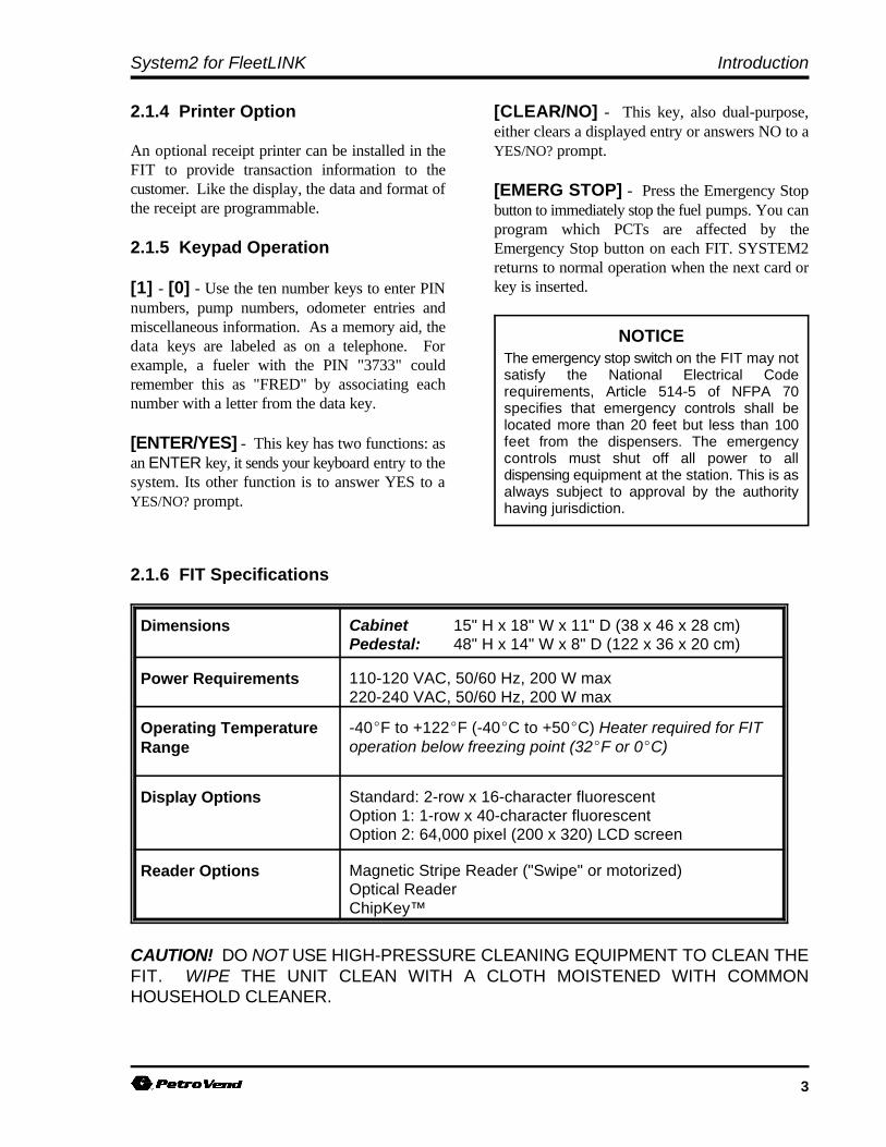
2.1.6 FIT Specifications
Dimensions Cabinet 15" H x 18" W x 11" D (38 x 46 x 28 cm)Pedestal: 48" H x 14" W x 8" D (122 x 36 x 20 cm)
Power Requirements 110-120 VAC, 50/60 Hz, 200 W max220-240 VAC, 50/60 Hz, 200 W max
Operating Temperature Range
-40EF to +122EF (-40EC to +50EC) Heater required for FIToperation below freezing point (32EF or 0EC)
Display Options Standard: 2-row x 16-character fluorescentOption 1: 1-row x 40-character fluorescentOption 2: 64,000 pixel (200 x 320) LCD screen
Reader Options Magnetic Stripe Reader ("Swipe" or motorized)Optical ReaderChipKey™
CAUTION! DO NOT USE HIGH-PRESSURE CLEANING EQUIPMENT TO CLEAN THEFIT. WIPE THE UNIT CLEAN WITH A CLOTH MOISTENED WITH COMMONHOUSEHOLD CLEANER.

SYSTEM2 Operator's Guide
4 10/15/97
More information on these OPTfeatures is located in the OPT User’sGuide.
2.2 Outdoor Payment Terminal (OPT)
The OPT is a dual-sided terminal. It emulatesa standard System2 FIT, although it isdesigned to serve both sides of a fueling island.The OPT counts as two readers. Theconfiguration procedure for an OPT is similarto that of a FIT as well.
Like the regular FIT, the OPT works with aSystem2 Fuel Site Controller (FSC); allSystem2 FSC software works with the OPT aswell. With this configuration, a total of fourcard readers are supported (two regular FITsand one OPT).
G Pedestal and housing are made of treated steel,and are very rust-resistant
G Durable high-solid content paint finish - customcolors are available
G Doors are made of impact-resistant polycarbonateABS
G Hidden "quick-clip" door hinges - no uglyfasteners, and the doors slide out and pivot foreasy removal with no tools
G Circuitry of one OPT is completely separate fromthe other - if one fails, the other one keeps going
G The OPT contains no DIP switches or EPROMs -all system configuration is done through software,and can be done on site, without a terminal. Futureversions will permit remote downloading ofconfiguration data via a modem.
G Manager Mode permits the following:
- Password protected configuration data- Self-tests for display, keyboard, card reader,
receipt printer and RAM- Printer and display contrast adjustable- Comm ports can be set up and tested- Multiple network number input- Keyboard tone can be adjusted- Keyboard backlight brightness adjustment- Configuration data can be printed out
G Standard thermostatically-controlled heaters
G The backlit 2x16 "Supertwist" character displayis standard. An optional backlit graphics displayhas been improved in several ways:
- Transflexive technology works better in directsunlight
- Tilted display for wider range of comfortableviewing
- Contrast OPTimizer™ automatically setsdisplay contrast for optimal viewing in alltemperature and ambient lighting conditions.
G Graphics display screens are displayed quickly - auser can "type ahead" with their keypad entries,allowing faster fueling
G A precision-crafted push-pull card reader readstracks 1 and 2. The high-reliability unit features auser-replaceable head (no special tools required forreplacement). A motorized reader is also available.
G The illuminated keyboard is constructed of adurable weather-resistant material laid overstainless steel switch "domes". An alphanumerickeypad will be available in future releases of OPT.
G High-resolution thermal receipt printer hasintegral cutter, auto-paper loading, and self-testfeatures. Can be configured to print multiplecopies of a receipt. A 4-inch roll of paper canproduce up to 1,100 receipts. And, because it'sthermal, there are no ribbons to replace.
System2 for FleetLINK Introduction
5
2.3 Pump Control Terminal (PCT)
The PCT gathers the data from the pumps and formats it for the FSC. The PCT can either be built in to theFIT - as a PC board located behind the FIT PC board, or in the OPT counts as two readers. a separateindoor cabinet. See Figure below.
Up to four PCTs can be installed. There are twotypes of PCT installation (see above).C The PCT circuit board is located in the FIT
cabinet and the pump control relays aremounted in the FIT pedestal
An OPT enclosure cannot contain any PCTcomponents.
C The PCT board and pump control relays areplaced in a separate, indoor cabinet.
Both types of installation provide the following:C Easy access to pump control relaysC Active and passive pulser supportC Electronic and mechanical pulser supportC Pulser activation by current flow or handle
activation.
With optional Universal Pump Control(UPC) software, the FSC can authorize fuelingtransactions via a pump control console (such asused in a self service station).
For pumps controlled by a UPC, refer to the UPCOperator Guide.
PCT specifications are on the following page.

SYSTEM2 Operator's Guide
6 10/15/97
PCT Specifications
Dimensions (indoorcabinet style)
25" H x 16" W x 5" D(64 x 41 x 13 cm)
Power Requirements(indoor cabinet style)
110-120 VAC, 50/60 Hz, 100 W max220-240 VAC, 50/60 Hz, 100 W max
OperatingTemperature Range(indoor cabinet style)
32EF to +122EF (0EC to +50EC)
Pump Rating 3/4 HP, 120/240 VAC
Pulser COMPATIBILITY Contact/12VDC electronic, 40 Ma maxper pulser
RATE RATIO 1:1 to 1000:1 in 1-pulse increments
SPEED 6,000 pulses per minute (mechanicaltype), 100,000 pulses per minute(electronic type)
DUTY CYCLE 50%

System2 for FleetLINK Introduction
7
2.4 Fuel Site Controller (FSC)
The FSC processes data supplied over Petro-Net from the PCTs and FITs/OPTs. The FSC also contains allcard information and system configuration data.
The FSC manages the operations of the FIT(s) orOPTs, the terminal or computer, the journal printer,and an optional modem.
2.4.1 Installation Overview
The FSC must be installed indoors, and connectedto one of the FITs or OPTs using twisted pairwiring and rigid steel conduit.
Install the FSC as described in the System2Installation Manual. That manual also contains anillustration of the FSC board and descriptions of itsstatus LEDs and switches.
2.4.2 External Computer Connections
To communicate with the system, the FSC must beconnected to one of the following:
C A standard ASCII terminalC An IBM® or compatible computer C Any computer capable of ASCII
communications.
If not using an ASCII terminal, the PC ormainframe computer must be running an emulationprogram to simulate the operations of an ASCIIterminal. For terminal baud rate, see the table onthe following page, or the System2 InstallationManual.
2.4.3 Journal Printer
The journal printer is connected to the FSC PTRport to record transaction data and to print reports.
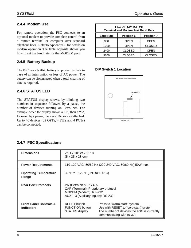
Front of FSC
DIP Switch 1
FSC shown with cover removed
SYSTEM2 Operator's Guide
8 10/15/97
FSC DIP SWITCH #1:Terminal and Modem Port Baud Rate
Baud Rate Position 6 Position 7
300 OPEN OPEN
1200 OPEN CLOSED
2400 CLOSED OPEN
9600 CLOSED CLOSED
DIP Switch 1 Location
2.4.4 Modem Use
For remote operation, the FSC connects to anoptional modem to provide complete control froma remote terminal or computer over standardtelephone lines. Refer to Appendix C for details onmodem operation The table opposite shows youhow to set the baud rate for the MODEM port.
2.4.5 Battery Backup
The FSC has a built-in battery to protect its data incase of an interruption or loss of AC power. Thebattery can be disconnected when a total clearing ofdata is required.
2.4.6 STATUS LED
The STATUS display shows, by blinking twonumbers in sequence followed by a pause, thenumber of devices running on Petro Net. Forexample, when the display shows a “1", then a “6",followed by a pause, there are 16 devices attached.Up to 40 devices (32 OPTs, 4 FITs and 4 PCTs)can be connected.
2.4.7 FSC Specifications
Dimensions 2" H x 10" W x 11" D(5 x 25 x 28 cm)
Power Requirements 110-120 VAC, 50/60 Hz (220-240 VAC, 50/60 Hz) 50W max
Operating TemperatureRange
32EF to +122EF (0EC to +50EC)
Rear Port Protocols PN (Petro-Net): RS-485CAP (Terminal): Proprietary protocolMODEM (Modem): RS-232AUX 1-3 (Auxiliary Inputs): RS-232
Front Panel Controls &Indicators
RESET button Press to "warm-start" systemFUNCTION button Use with RESET to "cold-start" systemSTATUS display The number of devices the FSC is currently
communicating with (0-32)

9
IMPORTANTOnly the normal or the restricted modemay be enabled at one time. When the`$' prompt displays, the restricted mode isenabled and the restricted password mustbe entered to proceed.
3.0 Operational Overview
Upon initial power-up, the first menu to appear isthe non-privileged Main menu. To enter privilegedmode, either type HELLO at the ">" prompt, thenenter the privileged password, OR use the MENUoption in the SYSTEM PARAMETERS menu.
Section 4 (Page 13) is a practice session, givingyou a chance to use most of the system features ina simulated site setup.
All commands can be reached via the menus;"regular" commands can be entered at the ">"prompt, if desired - use the MENUS option in theSYSTEM PARAMETERS menu to turn menusOFF or ON.
3.1 MAIN MENU
The first menu that appears after power is appliedto SYSTEM2 is the Main menu (see Page 25).
All system functions are accessed from the Mainmenu: System Access, System Times, SystemDevices, Customer Messages, System Parameters,Restrictions, Cards/Accounts, Transaction Data,System Totals, and Journal Printer. Each is brieflydescribed below; for a full description, turn to theindicated page.
A "Main Menu Outline" of all submenus accessedfrom the main menu is on Page 13.
3.2 SYSTEM ACCESS MENU
See Page 27. Use this menu to open or close thesystem, to open a connection to a modem, to changepasswords, or to use the "passthru" feature tocommunicate with other Petro-Vend products.
There are three levels of security in SYSTEM2:(1) normal, (2) restricted and (3) privileged.
Normal - The normal mode is the default mode.This mode does not have to be enabled. Nopassword is required. In this mode, you can printand display all system, card/key, account, andtransaction data.
Restricted - To safeguard SYSTEM2 data fromunauthorized viewing, you may enable therestricted mode. When System2 is in restrictedmode, a password must be entered before any datacan be displayed or printed. Restricted mode mustbe accessed before the privileged mode can beaccessed.
When the restricted mode is enabled, no commandswill be accepted and no characters will be echoed tothe screen until the Restricted password is entered.
SYSTEM2 Operator's Guide
10 10/15/97
Privileged - To configure SYSTEM2, the systemmust be in the privileged mode. To preventunauthorized tampering with the system, apassword is required.
To access privileged mode, select SYSTEMACCESS from the MAIN MENU. FromSYSTEM ACCESS menu, select HELLO andenter the main password (factory default"HELLO").. To exit privileged mode, enter BYE.
The system automatically exits from privilegedmode if no keyboard entry is made for 10 minutes.
The `DOWNLOAD' command must be enteredafter all `CONFIGURE' and `FORMAT'commands. You must enter the downloadcommand before the system will recognize anychanges! If several commands are entered, you donot have to do a download until after all commandsare entered.
To access the system using a PC and/or a modem,refer to Appendix D.
3.3 SYSTEM TIMES MENU
See Page 29. Use the System Times menu set thefollowing:
Q Real time and date
Q Date on which to change to (and from)daylight savings time
Q When to turn the system ON and OFF
Q When to turn the pocket lights ON and OFF.
3.4 SYSTEM DEVICES MENU
See Page 31. This menu lets you program thefollowing:
Q The FITs
Q The OPTs
Q The PCTs
Q The optional UPC (Universal PumpController)-equipped PCT.
3.4.1 FIT Programming Overview
The FIT controls the card/key reader(s), keyboard,display and optional /receipt printer. The followingfeatures can be programmed for each FIT:
R Whether to issue transaction receipts
R The time limit for issuing receipts
R Whether to allow keyboard entry of data
R Which PCTs to shut off when the EmergencyStop button is pressed
R If the card reader error counter should be reset
R Which pumps should be activated.
System2 for FleetLINK Introduction
11
3.4.2 PCT Programming Overview
The Pump Control Terminal boards are either inthe FIT pedestal or in a separate cabinet. EachPCT board controls the following parameters forup to eight pumps:
R Pump Number
R Pump Status
R Product Name
R Tank Number
R Quantity Restriction
R Total Time for Fueling
R Maximum Time for Pump Handle
R Maximum Time for First Pulse
R Maximum Time for MPD
R Pulser Divide Rate
R Pump Handle monitor
R Pump Sentry feature
3.4.3 UPC Programming Overview
The UPC can emulate up to four PCTs foroperation with a self-service console.
The UPC option enables SYSTEM2 to connect toa site console and provide simultaneous unattendedand self service fueling.
For complete details on UPC operation, refer to theUPC Operator Guide.
3.5 CUSTOMER MESSAGES MENU
See Page 37. This menu lets you:
Q Define receipt format and bonus points
Q Display prompts and keyboard responses
Q Create individual messages for fuelers
Q Specify a date/time format
3.6 SYSTEM PARAMETERS MENU
See Page 61. This menu lets you:
Q Display a system status report
Q Set a site ID
Q Specify fuel units, prices, and names
Q Define product "labels"
Q Create new passwords
Q Enable or disable the dual language feature
Q Enable or disable the menus
Q Enable or disable the response echo
Q Specify a coupon value ("bonus points")
Q Define the system memory size
Q Display the software version
Q Test the back-up battery
3.7 RESTRICTIONS MENU
See Page 67. This menu sets up the following:
Q Odometer Reasonability
Q Pump Restrictions
Q Quantity Restrictions
Q Security Table
3.8 CARDS/ACCOUNTS MENU
See Page 71. SYSTEM2 is activated via magneticcards, optical cards, or programmable ChipKeys,depending on the reader supplied with your system.
The SYSTEM2 can use single or dual card (orkey) operation. Three distinct types of card or keyare recognized:
Q Single
Q Driver
Q Vehicle
SYSTEM2 Operator's Guide
12 10/15/97
A record is maintained for each card, key, and/oraccount within SYSTEM2. Each record can beprogrammed with some or all of the following:
R Account/department number
R Expiration date
R Monthly allocation
R Daily allocation
R PIN (Personal Identification Number)
R Odometer entries
R Odometer reasonability with minimum andmaximum levels
R Pump or product restriction
R Quantity restriction per transaction
R Miscellaneous data prompting
R Driver name or vehicle description
R Card or ChipKey number
R Language type (first or second)
3.9 TRANSACTION DATA MENU
See Page 79. Use this menu to program thefollowing information for each transaction:
Q Driver and vehicle card/key numbers
Q Transaction and pump numbers
Q Product type, quantity and price
Q Keypad entries (for odometer entries andmiscellaneous data).
A "fixed length" format is used for all transactionrecords.
3.10 SYSTEM TOTALS MENU
See Page 83. All completed SYSTEM2transactions can be either printed or displayed.Using the System Totals menu you can restrict thetransactions you want to see by the followingparameters:
Q Date
Q Time
Q Transaction, card, account, or vehicle number
Q Pump
Q Fueltype
Q Day, shift, or midnight.
3.11 JOURNAL PRINTER MENU
See Page 87. The journal printer must be set beforeit can print SYSTEM2 data. You can temporarilyblock the transaction logging function to preventtransactions from being interspersed throughout areport printout.
System2 for FleetLINK Introduction
13
3.12 MAIN MENU OUTLINE
A. System Access
a. Openb. Closec. Calld. Helloe. Byef. Passthru
B. System Times (show/print/set)
a. Timeb. Time Changec. Dated. System ON Timee. Light ON Time
C. System Devices (show/ print/install/remove/configure a-f below)
a. FITb. PCTc. OPT 7. Month-End Totalsd. PCT & Position e. Pump f. Programg. Set Pump ONh. FIT Downloadi. PCT Downloadj. OPT Download
D. Customer Messages (show/ print/format)
a. Receipt Bodyb. Receipt Headerc. Receipt Trailerd. Receipt Bonus Pointse. Display Numberf. Keyboard Numberg. Messagesh. Date
E. System Parameters (show/print/set)a. System (show only)
- Current Time/Date- Installed FITs and PCTs- Low Tanks- Power failure times
b. Site IDc. Fuel Type Assignmentsd. Fueling Unitse. Password f. Language (dual ON/OFF)g. Menu (ON or OFF)h. Echo (ON or OFF)i. Bonus Points j. RAM (memory level 0-4)k. Version (software version)
F. Restrictions (show/ print/ set)
a. Odometer Reasonability (code 0-15)b. Pump Restriction (code 0-15)c. Quantity Restriction (code 0-15)d. Security (row 1/2)
G. Cards/Accounts (show/print/insert/ delete/ edit/ set/copy/ sort)
a. Card Number (show or print)b. Card Summary (show or print)c. Card Account Number (show or print)d. Account Number (show or print)e. Card Insert/Delete/Editf. Account Insert/Delete/Editg. Card Set
1. Specify Card/Account Buffer Size2. Define Card/Account Record3. Clear Card Record Totals4. Reconcile Card Record Totals5. Clear ALL Account Record Totals6.Reconcile Account Record Allocation
8. Set Keyboard Card Control Data9. Additional OptionsX. Exit
h. Copy Cardi. Sort
H. Transaction Data (show/print/ set/ clear)
a. Transaction by date/time/card/ account/vehicle(show or print)
b. Summary of "a" above (show/ print)c. Transaction by number (show/ print)d. Transaction Set or Cleare. Clear Transaction by date/sequencef. Report
I. System Totals (show/ print/ set/ clear)a. Transaction by date/time/card/ account/vehicle
(show or print)b. Summary of "a" above (show/ print)c. Midnight (show or print, eight days)d. Day (show or print, current day)e. Shift (show/print, change shift)f. Pump Totals (show, print, or clear)g. PCT Totals (show, print, or clear)h. Fuel Type Totals (show or print)i. Tank Totals (show, print, or set)
J. Journal Printer
a. Set, Show, Print Printer Configurationb. Lock or Unlock Printer

SYSTEM2 Operator's Guide
14 10/15/97
Notes:
15
CAUTIONThis is ONLY an exercise! When youare finished with this session, be sureto clear all the sample configurationdata from the system before puttingYOUR data into the system.
4.0 Practice Session
This section leads you step-by-step through atypical site configuration. This session assumesyour system is completely installed, and that thehardware has passed all self-diagnostics.
The references made in each step are to othersections of this manual where you can find - Via direct typed commands.complete details on the function used.
4.1 SESSION OVERVIEW
This exercise will let you do the following:
- Set the current time and date
- Set the memory (RAM) level of your system
- Define a fuel type
- Define a tank
- Create a FIT customer message andreceipt
- Configure the system for a printer
- Define a simple card base
- Configure and install a PCT/Position
- Configure and install a FIT
- Create an individual card record
- Create an account
- Generate transactions
- Define and run a report.
4.2 STEP-BY-STEP PROCEDURE
Issue commands in one of two ways:
- Via menus (takes longer, but the related functionsof the system are easier to understand)
This manual is organized around the menus, butthis does not mean you MUST use the menus. Formore information about menus and command lines,see Page 9.
This practice session uses both methods; chooseyour preferred method, but it is suggested you atleast try both methods.
4.2.1 Terminal Connection & Power-Up
1. To issue any commands to the system, you mustfirst have an RS232 terminal connected to theFSC TERM port. Set the terminal to the baudrate the FSC is set for (factory default is 1200),full-duplex communication, with 7 data bits, 1stop bit, even parity.
2. Apply power to all system components. Afterself-tests, the following prompt (the "non-privileged" prompt) should be on the terminal:
>Press the [ENTER] key several times toconfirm the system is receiving commands. Theprompt will repeat.
3. Enter the "privileged" mode by doing thefollowing: (1) Type HELLO and press[ENTER], (2) Type the password and press[ENTER]. From the factory, the originalfactory password is HELLO. The promptchanges to the following:
P>The system is now in Privileged mode, allowingyou to set or configure it.
SYSTEM2 Operator's Guide
16 10/15/97
4.2.2 Should You Use the Menus?
This manual is organized around the menus that arebuilt into the system software. All menus "branchout" from a Main menu; the Main menu isdisplayed after you power up the FSC and terminal,and press the [ENTER] key several times.
Turn the menus ON or OFF by typing SET MENU(and pressing [ENTER]) at the P> prompt.Answer Y or N at the ENABLE MENUS? promptas desired.
You can use the menus to guide you through thesetup procedure, or you can enter commandsdirectly at the P> prompt. Both methods areprovided in this practice session.
4.2.3 Set the Time and Date
Menu Method
1. From the Main menu:
Press [B] [ENTER].
2. From the System Times menu:
Press [C] [ENTER] [A] [ENTER]
3. At the SET TIME prompt, enter the time ofday. For example, at 3:15 PM:
Type 3:15 PM [ENTER] [ENTER].
4. You should be back in the System Times menu.Next, set the date:Type [C] [C] [ENTER]
5. At the SET DATE prompt enter the currentdate. For example, to set a date of March 21,1994:
Type MAR 21 1994 [ENTER] [ENTER].
6. Press [ENTER] once again to return to theMain menu.
Command Line Method
1. At the P> prompt:
Type SET TIME [ENTER].
2. At the SET TIME prompt, enter the time ofday. For example, at 3:15 PM:
Type 3:15 PM [ENTER].
3. You should be back to the P> prompt. Next, setthe date:
Type SET DATE [ENTER]
4. Enter a date. For example, to set a date ofMarch 21st, 1994:
Type MAR 21 1994 [ENTER]. Your entry isechoed, and the P> prompt reappears.
4.2.4 How Much Memory in the System?(Page 61).
This procedure tells the system software how muchRAM memory is in your system. The amount isdetermined by a code number.
Menu Method
1. From the Main menu:
Press [E] [ENTER].
2. From the System Parameters menu:
Press [C] [ENTER] [J] [ENTER]
3. At the ENTER OPTION prompt, enter a RAMlevel. For example, to define Level 2:Type 1 [ENTER] [ENTER].
You should be back in the System Parametersmenu. Press [ENTER] once again to return tothe Main menu.
Command Line Method
1. At the P> prompt:
Type SET RAM [ENTER].
2. At the ENTER OPTION prompt, enter a RAMlevel. For example, to define Level 2:Type 1 [ENTER] [ENTER].
This returns you to the P> prompt.
System2 for FleetLINK Introduction
17
4.2.5 What Kind Of Fuel? (Page 61) 4.2.6 What Kind Of Tank? (Page 83)
This section defines fueltype code #1 as being This section shows how to define a sample Tank #1unleaded premium gasoline, selling for $1.39 a as containing 9600 gallons of premium unleadedgallon. gasoline. The sample tank will alert the system
Menu Method
1. From the Main menu:
Press [E] [ENTER].
2. From the System Parameters menu:
Press [C] [ENTER] [C] [ENTER].
3. At the ENTER FUELTYPE: prompt:Type 1 [ENTER]. The current name and priceof fueltype #1 appears, along with a list ofFueling Unit Codes (1-3). 3. At the ENTER TANK: prompt:
4. At the ENTER FUELING UNIT CODE (1-3): prompt:Type 1 [ENTER].
5. At the CHANGE PRICE? (Y/N): prompt:Type Y [ENTER] 1.39 [ENTER]
6. At the CHANGE PRODUCT NAME (Y/N)?:prompt: Type PREMUNLEAD [ENTER].
7. Press [ENTER] ENTER] to return to the Mainmenu.
Command Line Method
1. At the P> prompt:
Type SET FUELTYPE 1 [ENTER].
2. Follow Steps 4-6 in the "Menu Method" above.
3. Press [ENTER] to return to the P> prompt.
when its level drops to 1200 gallons.
The "fuel type" was defined in Section 4.2.5.
Menu Method
1. From the Main menu:
Press [I] [ENTER].
2. From the System Totals menu:
Press [J] [ENTER].
Type 1 [ENTER].
4. At the FUEL TYPE CODE (1-16): prompt:Type 1 [ENTER].
5. At the ENTER QUANTITY: prompt:Type 9600 [ENTER]
6. At the LOW LEVEL QUANTITY: prompt:Type 1200 [ENTER]. You will now see asummary of Tank 1.
7. Press [ENTER] [ENTER] to return to theMain menu.
Command Line Method
1. At the P> prompt:
Type SET TANK 1 [ENTER].
2. Follow steps 4-6 in the "Menu Method" above.
3. Press [ENTER] to return to the P> prompt.
SYSTEM2 Operator's Guide
18 10/15/97
MESSAGE 1 DISPLAY #8:PETRO VEND SYSTEM2
:Lang 1 :: :X
4.2.7 Introduce Yourself to the Customer(Page 37)
This section gives you practice with programminga 2 x 16 FIT display to give details on the "ABCOIL COMPANY", and creating a custom receiptheader and trailer with details about the "ABC OilCompany", and its "special offer".
Menu Method
1. From the Main menu:
Press [D] [ENTER].
2. Create A LCD Display: From the CustomerMessages menu:
Press [C] [ENTER] [E] [ENTER].
3. At the ENTER DISPLAY: prompt type 8[ENTER]. The current Message #8 appears(factory default is PETRO VEND SYSTEM2)along with an entry field for your new message.The figure below shows the display; the cursoris shown by an "X".
4. The space between each set of colons representsa line break on the display. Type ABC OIL.Press the space bar until the cursor is within thesecond set of brackets, then type COMPANY.
5. Press [ENTER] [ENTER] to complete theentry and return to Customer Messages menu.
6. Create The Receipt Header: From theCustomer Messages menu, press [C] [ENTER][B] [ENTER]. A prompt similar to the one forthe display (Step 3) appears.
7. Type ABC OIL CO. [ENTER]. Whenprompted for "RED PRINT?", just press[ENTER] again. Then:
- Type 1234 SMITH ST. [ENTER][ENTER].
- Type ANY TOWN USA [ENTER][ENTER].
- Type 555-1234 [ENTER] [ENTER][ENTER].
8. Create A Receipt Trailer. From the CustomerMessages menu, press [C] [ENTER] [C][ENTER]. A prompt similar to the one for theheader appears.
9. Type SPECIAL! [ENTER]. When promptedfor "RED PRINT?", just press [ENTER] again.Then:
- Type 10W30 OIL [ENTER] [ENTER]
- Type .89 PER QT [ENTER] [ENTER]
- Type STOCK UP NOW [ENTER][ENTER] [ENTER]
10. Download. From the Main menu:
- Press [C] [ENTER].
- From the System Devices menu:
Press [G] [ENTER]
This completes the display, header and trailercreation via the menus.
Command Line Method
1. At the P> prompt:
Type FORMAT DISPLAY 8 [ENTER]. Thedisplay shown above in "Menu Method"appears.
2. Follow Step 4 in the "Menu Method" above.
3. Press [ENTER] twice to complete your entryand return to the P> prompt.
4. Create A Receipt Header: At the P> prompt:
Type FORMAT REC HE [ENTER].

System2 for FleetLINK Introduction
19
5. Follow Step 7 in the Menu Method to createyour header. Then, press [ENTER] until yousee the P> prompt again.
6. Create A Receipt Trailer: Type FORMATREC TRAILER at the P> prompt.
7. Follow Step 9 in the Menu Method. Press[ENTER] when done to complete your footerand return you to the P> prompt.
8. Download your changes. Type DOWNLOADand press [ENTER].
This completes the display and receipt practice.
4.2.8 Tell The System About YourTransaction Records (Page 87)
You can specify what data is printed on the printer.Do the following.
Menu Method
1. From the Main menu:
Press [J] [ENTER].
2. From the Journal Printer menu:
Press [C] [ENTER].
3. Answer all the prompts by pressing Y followed each card you have in your system.by [ENTER].
4. After the last prompt, press [ENTER] once CARD/ACCOUNT RECORD? Press Yagain to return to the Journal Printer menu.
Command Line Method Now begins the actual card definition. For this
1. At the P> prompt:
Type SET JOU [ENTER].
2. Answer all the prompts by pressing Y followedby [ENTER].
4.2.9 How Many Cards? What ShouldThey Say? (Page 71)
You can tell the system how many card records itcan handle, and what data each card can process.
Menu Method
1. From the Main menu:
Press [G] [ENTER].
2. From the Cards/Accounts menu:
Press [F] [ENTER].
3. From the Set Card menu:Press [1] [ENTER]. Answer Y to the...CLEARED? confirmation request.
4. - Answer N to ENABLE MESSAGING?- Enter 1 for TRANSACTION SIZE CODE
You will now see how many messages thesystem will hold, for cards that have NOoptions set and cards that have ALL options set.
5. Answer Y [ENTER] to the SAVE THISCONFIGURATION? prompt. You arereturned to the Set Card menu.
6. From the Set Card menu, press [2] [ENTER].This step defines which options are enabled for
7. The first prompt is SPECIFY
[ENTER]. Press Y [ENTER] again at theconfirmation request.
exercise you will create a card with all possibleoptions enabled EXCEPT for the Expiration Date,Daily Allocation, and Odometer Reasonabilityoptions.
8. For each prompt, press Y [ENTER] except forthe three exceptions above, which you shouldanswer with N.
SYSTEM2 Operator's Guide
20 10/15/97
At the end of this process you will see how many 8. Provide the system with pump pulsercards this particular configuration will let you use.
9. Press [ENTER] once again to return to theCards/Accounts menu.
Command Line Method while dispensing fuel, it will not continue to
1. At the P> prompt:
Type SET CARD [ENTER].
2. Follow the Menu Method, beginning with Step3 and ending with Step 8.
3. Press [ENTER] to return to the P> prompt.
4.2.10 Configure and Install a PCTPosition (Page 31)
This part of the exercise tells you how to define apump for the system: its number, pulses per unit offuel, how much fuel it should dispense, and varioustimeout limits.
Menu Method
1. From the Main menu:
Press [C] [ENTER].
2. From the System Devices menu:
Press [E] [ENTER] [B] [ENTER]
For each of the following entries, remember youmust press the [ENTER] key after each entry.
3. Give the PCT a number. Type 1 at the ENTERPCT: prompt.
4. Answer N to the IS THIS A UPC prompt.
5. Press [E] [ENTER] [C] [ENTER]
6. Define a position for the pump. Type 1 at theENTER POSITION: prompt.
7. Give the pump a number. Type 1 at theENTER PUMP prompt.
information. Type 10 at the ENTER PULSESPER GALLON: prompt.
9. Specify how much fuel the pump is allowed todispense per transaction. This entry is a safetyfeature: if the nozzle falls out of the filler neck
spew fuel indefinitely. Type 50 at the MAXFUEL TO BE DISPENSED PERTRANSACTION prompt.
10. Enable the "Pump Sentry". This featureautomatically disables a pump if it registerszero product in three consecutive transactions.Type Y at the PUMP SENTRY OPTIONSprompt, and again at the ENABLE PUMPSENTRY prompt.
11. Another safety feature is the MaximumFueling Time limit. Type 15 at the MAXTIME ALLOWED FOR FUELING (MIN)prompt.
12. To prevent a pump from being turned ON andthen "forgotten", a Time To Retrieve PumpHandle feature is provided. Type 90 at theMAX TIME ALLOWED TO RETRIEVEPUMP HANDLE (SEC) prompt. Also, enter60 at the MAX TIME ALLOWED TODETECT FIRST FUELING PULSEprompt.
13. Specify the maximum time between startingand stopping the fuel flow: type 30 at theMAX TIME ALLOWED BETWEENFUELING PULSES (SEC) prompt.
14. Specify a fuel type; for this example, type 1(premium unleaded) at the ENTERFUELTYPE CODE prompt. Type 1 at theENTER TANK prompt. Clear the pump totalsby typing Y at the CLEAR PUMP TOTALSprompt. Finally, enter a new totalizer value of14,500.

System2 for FleetLINK Introduction
21
PCT 1 POSITION 1 PUMP 1PULSES PER GALLON: 1ABSOLUTE MAX QUANTITY: 50 GALLONPUMP INACTIVEPUMP SENTRY: ENABLED *** PUMP TIME-OUTS ***TOTAL FUELING TIME-OUT (MIN): 15PUMP HANDLE TIME-OUT (SEC) : 90FIRST PULSE TIME-OUT (SEC) : 60MISSING PULSE TIME-OUT (SEC): 30FUELTYPE CODE TANK# TOTALS TOTALIZER1: UNLEAD 1 0.0 14500.0
15. Press [ENTER] once again. You should nowbe back in the System Devices menu. Confirmyour PCT/position/pump setup by typing A[ENTER] C [ENTER], and then enter 1, todisplay the following screen:
16. Install the PCT position. From the SystemDevices menu, type [C] [ENTER] [C][ENTER]. Then, enter 1 for the PCT and 1for the POSITION (press [ENTER] aftereach). When you see PCT 1 POSITION 1OKAY, press [ENTER] to return to theSystem Devices menu.
17. Download your changes (use the sameprocedure described earlier).
Command Line Method
1. At the P> prompt:
Type CONFIG PCT 1 POS 1 [ENTER].
2. Follow the Menu Method beginning with Step 5and ending with Step 12. Press [ENTER] untilyou see the P> prompt again.
3. Install the position by typing INST PCT 1POS 1 [ENTER] at the P> prompt.
4. Download your changes. The procedure isdescribed earlier.
The PCT position has been installed when you seeOKAY.
4.2.11 Configure & Install a FIT (Page 31)
Your sample Fuel Island Terminal will do thefollowing: Issue receipts within a month of thetransaction, clear the receipt counter, and shut offPCT position 1 when the E-stop button is pressed.The access to pumps will not change.
Menu Method
1. From the Main menu:
Press [C] [ENTER].
2. From the System Devices menu:
Press [E] [ENTER] [A] [ENTER]
For each of the following entries, remember youmust press the [ENTER] key after each entry.
3. Define FIT #1 by typing 1 [ENTER] at theENTER FIT: prompt.
4. Since you want the FIT to issue receipts,answer Y [ENTER] to the ISSUERECEIPTS? prompt. Then, enter 30 (onemonth) for the LIMIT TO RECEIVERECEIPT.. prompt. Answer NO to the CLEARRECEIPT COUNTER? prompt.
5. Answer N [ENTER] to the KEYBOARDOPTIONS? prompt.
6. You want a customer to be able to shut off PCT1 with the Emergency Stop button, so press Y[ENTER] to the SPECIFY PCTs TO SHUTOFF... prompt. Then, press 1 [ENTER] tospecify PCT 1 will be the only PCT to shut off.Answer NO to CHANGE FIT ACCESS TOPUMPS?

SYSTEM2 Operator's Guide
22 10/15/97
FIT NOT INSTALLEDRECEIPT: 0 30 DAY LIMITKEYBOARD ACCESS: DISABLEDPCTS TO SHUT OFF ON E-STOP: 1CARD READER ERROR COUNTER: 0-- ACCESS TO ALL PUMPS
After pressing [ENTER] following the PCT entry,a summary of the FIT should appear on yourmonitor (shown below).
Press [ENTER] to return to the System Devicesmenu.
7. Install the FIT. From the System Devices menu:Press [C] [ENTER] [A] [ENTER].
Enter the FIT number. Press [ENTER] to useFIT #1. Now, do a download (describedearlier).
You will see OKAY. Press [ENTER][ENTER] to return to the Main Menu.
Command Line Method
1. At the P> prompt:
Type CONFIG FIT 1 [ENTER]. You will seeISSUE RECEIPTS?
2. Follow the Menu Method beginning with Step 4and ending with Step 6. Press [ENTER] untilyou see the P> prompt again.
3. Install the FIT. Type INSTALL FIT 1[ENTER] at the P> prompt. You will seeOKAY, and the P> prompt re-appears.
4. Do a download (described earlier).
4.2.12 Create a Sample Card File &Account
This section lets you create a card file and anaccount, and then assign the card to the account.
Menu Method
1. From the Main menu:
Press [G] [ENTER].
2. Create (Insert) a new card: From theCards/Accounts menu:
Press [C] [ENTER] [E] [ENTER]
3. To define your card settings, answer thefollowing prompts as indicated:
- AUTO-GENERATE PIN. Type N[ENTER]
- CARD #? Type 1 [ENTER]- CARD TYPE (S)ingle (D)river
(V)ehicle) Type S [ENTER]
- VALID? Type Y [ENTER]- ACCOUNT # (0-9999) Type 100
[ENTER]- MONTHLY ALLOCATION: $ Type 500
[ENTER]- ENABLE MISC ENTRY? Type Y
[ENTER]- PIN#: Type 1234 [ENTER]- ENTER CURRENT ODOM?: Type Y
[ENTER]- PUMP RESTRICTION CODE: Type 1
[ENTER]- QUANTITY RESTRICTION CODE: Type
1 [ENTER]
- DRIVER NAME: Enter your first name here and press [ENTER].
OPTIONAL: Program another card if you want bypressing Y [ENTER] at the ANY MORECARDS? prompt. Otherwise, go on to the nextsection to make an account.

System2 for FleetLINK Introduction
23
CARD#: 99SINGLE CARDACCOUNT#: 0100MONTHLY ALLOCATION: $500.00--TOTALS TO DATE: 0.00MISC ENTRY: ENABLEDPIN #: 1234ODOMETER: ENABLEDPUMP RESTRICTION CODE: 1QUANTITY RESTRICTION CODE: 1DRIVER NAME: YOUR NAME
ACCOUNT#: 0100ACCOUNT RECORDDISCOUNT (%): 15.0MONTHLY ALLOCATION: $5000.00--TOTALS TO DATE: 0.00PUMP RESTRICTION CODE: 1QUANTITY RESTRICTION CODE: 1DRIVER NAME: YOUR NAME
4. Verify your card record: From theCards/Accounts menu press A [ENTER] A menu.[ENTER] 99 [ENTER]. You should see thefollowing:
5. Press [ENTER] again until you see theCards/Accounts menu.
6. Create your account. This account will beAccount #100. Card 99 will be part of it. Allpurchases billed to Account 100 will have a15% discount when billed through the ReportPackage. All cards within Account 100 will beable to draw a total of $5000.00 worth ofproducts per month - no more.
To create your account from the Cards/Accountsmenu: Press C [ENTER] F [ENTER] 100[ENTER].
7. To define your account, answer the followingprompts as shown:
- VALID? Press Y [ENTER]- ACCOUNT DISCOUNT Press 15
[ENTER]- MONTHLY ALLOCATION Type 5000
[ENTER]- PUMP RESTRICTION CODE: Type 0
[ENTER]- QUANTITY RESTRICTION CODE: Type
1 [ENTER]
- ACCOUNT NAME: Type your nameand press
[ENTER]- ANY MORE ACCOUNTS? Type N
[ENTER]. You will see SORTINGCARD/ACCOUNT DONE. Press
[ENTER] to return to the Cards/Accounts
8. To view or edit the account from theCards/Accounts menu press E [ENTER] F[ENTER] 100 [ENTER]. The summary ofAccount 100 appears:
9. Press [ENTER] after each line to say you donot want to change it (unless you see an error).
Command Line Method
1. At the P> prompt:
Type INSERT CARD [ENTER]. First you areasked AUTOMATICALLY GENERATE PINNO? Type N. You will see ENTER CARD #.Type 99 [ENTER].
2. Follow Step 3 in the Menu Method, to defineyour card information. To review your cardsetup, type SHOW CARD 99 at the P>prompt. You will see POSITIVE CARDFILE... and a message telling you how manycards are used and how many cards thisconfiguration will allow.
3. Create your account. Type INSERTACCOUNT [ENTER] at the P> prompt. Type100 [ENTER] at the ACCOUNT # prompt.
4. Follow the Menu Method Step 7.
5. Verify the account setup by typing EDITACCOUNT [ENTER]. Then, enter 100[ENTER].
6. Press [ENTER] for each correct line.
SYSTEM2 Operator's Guide
24 10/15/97
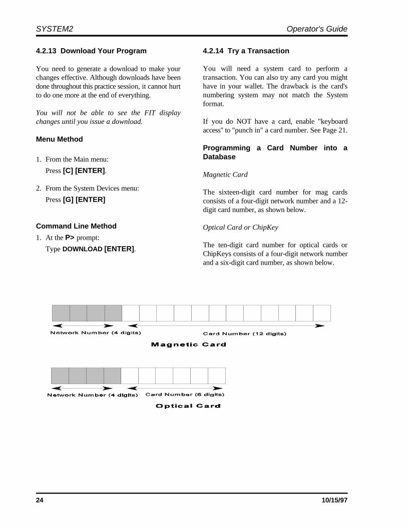
4.2.13 Download Your Program 4.2.14 Try a Transaction
You need to generate a download to make yourchanges effective. Although downloads have beendone throughout this practice session, it cannot hurtto do one more at the end of everything.
You will not be able to see the FIT displaychanges until you issue a download.
Menu Method
1. From the Main menu:
Press [C] [ENTER].
2. From the System Devices menu:
Press [G] [ENTER]
Command Line Method
1. At the P> prompt:
Type DOWNLOAD [ENTER].
You will need a system card to perform atransaction. You can also try any card you mighthave in your wallet. The drawback is the card'snumbering system may not match the Systemformat.
If you do NOT have a card, enable "keyboardaccess" to "punch in" a card number. See Page 21.
Programming a Card Number into aDatabase
Magnetic Card
The sixteen-digit card number for mag cardsconsists of a four-digit network number and a 12-digit card number, as shown below.
Optical Card or ChipKey
The ten-digit card number for optical cards orChipKeys consists of a four-digit network numberand a six-digit card number, as shown below.

25
MAIN MENU---------
A - SYSTEM ACCESSB - SYSTEM TIMESC - SYSTEM DEVICESD - CUSTOMER MESSAGESE - SYSTEM PARAMETERSF - RESTRICTIONSG - CARDS/ACCOUNTSH - TRANSACTION DATAI - SYSTEM TOTALSJ - JOURNAL PRINTER
'RETURN' FOR COMMAND LINE
ENTER CATEGORY:
Part II - Programming5.0 Menu Overview
5.1 USING THE MENUS
The system is initially in "command line" mode,meaning you must issue commands at the ">"prompt (such as > SET TIME). Menus areavailable, however, to simplify operations.
To turn the menus ON, do the following:
1. Get into the privileged mode by entering theprivileged password at the prompt.
2. Enter SET MENU at the P> prompt (`P>').
3. When the message `ENABLE MENUS(Y/N)?' appears, enter Y.
If you do not enable the menus, SYSTEM2continues to operate in "command line" mode,which is the mode used in the Petro-Vend K2500.
To suspend the menus for one command, press[ENTER] several times at the prompt, until thecommand line reappears. After the command isentered at the command line, the menus reappear.
Use the SET MENU command to enable or disablethe menus for your entire programming session.
To select a menu item, simply press the matchingletter key, followed by the [Return] (or [ENTER])key. For example, to select "System Access", pressthe [A] key, then press the [Return] key. You canuse the backspace key ([77]) to change yourselection before pressing the [Return] key.
A submenu is displayed after you select an itemfrom the MAIN MENU.
To display a help screen for the MAIN MENU,type `?', then press [ENTER].

SYSTEM2 Operator's Guide
26 10/15/97
5.2 COMMANDS & OPTIONS 5.3 HELP SCREENS
Some menus require you type only a lettercorresponding to a command (such as SET) to A help screen is available for each item listed in theactivate a particular function; others require first a submenus. These screens display informationcommand and then an option (such as INSTALL, about the current menu.followed by PCT).
A "menu tree" with relevant commands (arranged usual manner but type a question mark (?) beforefor menus use) appears on Page 13. The three most pressing [ENTER].used commands are SHOW, PRINT and SET:
- SHOW. Displays information from aSYSTEM2 data base on the screen of yourterminal or PC. This command does not require [ENTER].privileged status.
- PRINT. Sends data to your external journalprinter to make a hard copy. Most (but not all) [ENTER] key a second time.information can be printed, including all setupdata (cards, accounts, fueltypes, prices, etc.) To return to the MAIN MENU, press theand all transaction information (time, date,amount, price, cost, etc.). This command doesnot require privileged status.
- SET (FORMAT and CONFIGURE worksimilarly). These commands are used to enteror change the setup data. These commands areprivileged. Note that after FORMAT orCONFIGURE commands is used, one of the`DOWNLOAD' commands must then beentered.
Other menu commands are listed below:
- INSERT, DELETE, EDIT, COPY, SORT -These commands are used with the card andaccount files. Some are privileged commands,some are not.
- INSTALL/REMOVE - These commandsactivate and deactivate a device (such as aPCT). Privileged commands.
- CLEAR - There are several CLEARcommands, which erase transactions from thesystem data base. Privileged command.
- REPORT - activates the optional ReportPackage. Privileged command.
To get a help screen, select a menu item in the
For example, to display the help screen for SETTIME, type `C' (for the command) from the SystemTimes menu, and then type `A?' and then press
To return to a current submenu, press the
[ENTER] key until the Main menu reappears.
For help from a command line, type HELP at eitherthe privileged or non-privileged prompt.

27
-------------SYSTEM ACCESS ** PRIVILEGED **--------------------------------A: OPENB: CLOSEC: CALLD: HELLOE: BYEF: PASSTHRU--------------------------------^ENTER COMMAND:
CAUTIONClosing the system with the CLOSEcommand is not the same as pressingthe Emergency Stop button! EmergencyStop removes power from the pumpsand interrupts the pumping process.
6.0 System Access Menu
From MAIN menu, press [A]
6.2 HELLO/BYE6.1 OPEN/CLOSE
The OPEN and CLOSE commands give immediateaccess to pumps. Both commands are privileged,requiring the main password.
When a CLOSE command is issued, all activities inprogress (pumping, printing a receipt, etc.)complete normally but no new activities areallowed to begin.
HELLO is used to access the privileged mode.You'll be prompted for the system password (thefactory default password is `HELLO').
The BYE command exits the privileged mode.
Use the privileged mode to enter and change setupdata. You MUST enter the "main" password toPrivileged mode.
To return to normal mode from the command line$> prompt, type BYE.
See Page 63 for information on changing yourpasswords.

SYSTEM2 Operator's Guide
28 10/15/97
6.3 CALL
The CALL command creates a virtual link betweenthe TERMINAL port and the MODEM port on theFuel Site Controller.
Before executing the CALL command, a modemand terminal must be connected to the MODEMand TERMINAL ports, respectively.
After executing CALL, you can use a terminalconnected to the FSC TERMINAL port to issuedialout commands directly to the modem.
To break the connection, type BYE.
6.4 PASSTHRU
The PASSTHRU command lets two intelligentdevices (such as a Petro Vend SiteSentinel and aSYSTEM2) "talk" to each other via only oneterminal. The terminal can be connected to either ofthe devices.
The second device must use the RS-232 standardinterface, and must be set at the same baud rate andparity as the SYSTEM2: 7-bit, even parity, 1 stopbit.
Connect the second device (for example, theSiteSentinel) to the AUX3 port on the SYSTEM2.The terminal goes to the TERMINAL port asbefore. This must be done before issuing thePASSTHRU command.
After you issue the PASSTHRU command,SYSTEM2 enters a "transparent" mode, wherecharacters sent to it by the terminal or a modem arepassed through to the second intelligent device. Anycharacters coming from the other device wouldlikewise pass through to the terminal or modem.
Press [CNTL] [Z] to break the passthruconnection.
29
------------SYSTEM TIMES ** PRIVILEGED **-------------------------------
A: SHOW A: TIMEB: PRINT B: TIME CHANGEC: SET C: DATE
D: SYSTEM ON TIMEE: LIGHT ON TIME
---------------------------------------^ENTER COMMAND: ^ENTER OPTION:
7.0 System Times Menu
From MAIN menu, press [B]
7.1 TIME
The SHOW TIME or SET TIME commanddisplays or sets the current time of day. The SETTIME command changes time as follows:
1. After issuing the command, you are promptedto enter the time.
2. Enter the time in the format: `hh:mmam/pm'. For example, 12:57 PM.
If PM is not specified, AM is assumed.
3. Press the [ENTER] key to complete the entry;this sets seconds to zero. The new time andcurrent (or default) date are displayed.
Press [ENTER] to leave the current timeunchanged.
7.2 TIME CHANGE
The SET TIME CHANGE command sets dates onwhich the internal clock moves ahead or back byone hour, to adjust for the change between daylightsavings time and "standard" time. The changeoccurs at 2:00 AM on the date specified.
The SHOW TIME CHANGE command displayschange dates in the system. The SET TIMECHANGE command changes the dates as follows:
1. After issuing the command you are prompted:
ENTER DATE WHEN TIME IS MOVED BACK 1HOUR:
2. Enter the "move-back" date in the formatmmm dd yyyy (the year must be four digits).Press [ENTER].
3. The following prompt appears:
ENTER DATE WHEN TIME IS MOVED AHEAD 1HOUR:
Enter the "move ahead" date in the same way.The word CHANGE can be abbreviated CH inthese and other line commands.

SYSTEM2 Operator's Guide
30 10/15/97
7.3 DATE
The SHOW DATE or SET DATE commanddisplays or sets the current date within the system'smemory. The SET DATE command changes thedate as follows:
1. After issuing the command you are prompted toenter a date: ENTER DATE (MMM DD, YYYY):
2. Enter the date in the indicated format (forexample, type FEB 11, 1994 for February11th, 1994.
3. Press the [ENTER] key to complete the entry;the new date is now displayed.
Press [ENTER] to leave the current dateunchanged.
7.4 SYSTEM ON TIME
The SHOW SYS TIME and SET SYS TIMEcommands display or set the time the system goesON and OFF, and the time during which only"transactions in progress" can be performed("receipts only" time).
The SET SYS TIME command lets you set thefollowing four options (time for the first three isentered in the same format as for System Time -hh:mm).
SYSTEM ON TIME - specifies when SYSTEM2goes active. When the system is on, it displaysmessages, and accepts card insertions or keypadentries.
SYSTEM OFF TIME - specifies when the systemgoes inactive. No new transactions are allowed tobegin, but any in progress are allowed to finish.
RECEIPTS ONLY TIME - specifies when thesystem allows no new transactions to begin, butdoes allow "just completed" customers to get theirreceipts. This time would typically precede the`SYSTEM OFF TIME' by several minutes.
For example, a gas station that dispenses fuel from9:00 AM until 7:00 PM would have the `SYSTEMON TIME' set to 9:00 AM, the `SYSTEM OFFTIME' set to 7:10 PM and the `RECEIPTSONLY TIME' set to 7:00 PM.
TIME ADJUST - this feature allows a softwareadjustment to the internal time clock. In the eventof a noticeable time drift, a number of seconds canbe added to or subtracted from each day, until aproper hardware adjustment can be made.
7.5 LIGHT ON TIME
The SET LIGHT command lets you set theSYSTEM2 to turn the "pocket" lights in thestandard FIT ON and OFF at designated times.
After selecting this option, the following promptsappear:
ENTER LIGHT ON TIME:ENTER LIGHT OFF TIME:
Enter time in the same format as that for SYSTEMON TIME (previous section).

31
SYSTEM DEVICE ** PRIVILEGED **---------------------------------A: SHOW A: FIT #...B: PRINT B: OPT #...C: INSTALL C: VIT #...D: REMOVE D: PCT #...E: CONFIGURE E: PCT #..POSITION#..
F: PUMP #...G: PROGRAM
-----------------------------------------F: SET H: PUMP ON-----------------------------------------G: DOWNLOAD-----------------------------------------H: DOWNLOAD I: FIT (#...)
J: OPT (#...)K: PCT (#...)
-----------------------------------------^ENTER COMMAND: ^ENTER OPTION:
8.0 System Devices Menu
From MAIN menu, press [C]
This section describes the System Devices menu by 8.1.1 Show FIT #explaining each of the available menu options: FIT#, OPT#, PCT #, PCT #/Position #, Pump # and Issuing a SHOW FIT command, along with a validProgram. Commands applicable to each option are FIT number, displays the following message:described in each section.
8.1 FIT #
The SHOW, PRINT, INSTALL, REMOVE andCONFIGURE FIT # commands let you view,configure, install or remove FITs, and determine ifthe receipt printer will issue receipts, whether thekeyboard is enabled or disabled, which PCTs toshut off when the emergency stop button is pressed,and reset the card reader error counter.
The FIT number is set with a DIP switch on thePV-269 board - refer to the System2 InstallationManual to set the FIT number.
FIT INSTALLEDNO RECEIPTSKEYBOARD ACCESS - DISABLEDPCTs TO SHUT OFF ON E-STOP:1,2,3,4CARD READER ERROR COUNTER: 0-- ACCESS TO ALL PUMPS
Entries will vary depending on current FIT settings.The CONFIGURE FIT command (explained next)changes these settings.
See Appendix H for VIT (FleetLINK) details.

SYSTEM2 Operator's Guide
32 10/15/97
8.1.2 Configure FIT # CLEAR CARD READER ERROR COUNTER
The following prompts appear one by one afterusing CONFIGURE FIT #: This prompt is only displayed if the error counter
ISSUE RECEIPTS (Y/N)? - Enter Y to have theoptional receipt printer issue a receipt (N isdefault).If you enter [Y] to the ISSUERECEIPTS? prompt, two additional promptsappear;
ENTER LIMIT TO RECEIVE RECEIPT INDAYS(0..99) - this is the number of days after atransaction that a customer can receive areceipt. Default is NO LIMIT (press[ENTER]).
CLEAR RECEIPT COUNTER (Y/N)? - Thereceipt counter keeps a running total of allreceipts issued to date. It can be used to keeptrack of the receipt paper and to indicate whenthe paper is running low.
KEYBOARD OPTIONS (Y/N) ? - Default is N.Enter [Y] to display:
ENABLE KEYBOARD ACCESS (Y/N) ? -Default is N. With this feature enabled, acustomer can enter their card number on theFIT keyboard. For more details about"cardless" card records, see the INSERTCARD command on Page 73.
The card reader is not disabled by enablingkeyboard access.
SPECIFY PCTs TO SHUT OFF ON E-STOP(Y/N)? - Default is N (meaning ALL PCTs shut off upon E-STOP). If you enter [Y] to select which PCTs willbe turned off, you'll see:
ENTER PCTs TO SHUT OFF (#,#..) - Enter arange and press [ENTER].
If there are card reader errors logged, the nextprompt you'll see is:
(Y/N) ?
is greater than zero. This counter keeps a runningtotal of bad reads by the card reader.
The system defines a bad read as one where thecard reader cannot read a card correctly in threesequential attempts. Such a failure could indicatethat the card reader needs cleaning or replacement.
Enter [Y] to clear the counter. Enter [N] to keepthe counter the same and to display the nextprompt. The last FIT configuration prompt is:
CHANGE FIT ACCESS TO PUMPS (Y/N) ? -Default is N. Enter [Y] to change which pumps canbe activated by the specified FIT:
ENTER VALID PUMPS (p1, p2, ..)
If you enter [N], all pumps will be accessible fromthis FIT. You will see ALL PUMPS ACCESSED ifyou choose [N].
Enter the DOWNLOAD command after FITconfiguration.
8.1.3 Install FIT
This command activates the specified FIT,establishing a communication link between theinstalled FIT and the FSC.
FIT #1 is automatically installed on power-up.
8.1.4 Remove FIT
This privileged command stops the FSC fromcommunicating with the specified FIT.
System2 for FleetLINK Programming
33
8.2 OPT #
8.2.1 Show OPT #
Issuing a SHOW OPT command, along with avalid OPT number, displays the following message:
OPT INSTALLEDRECEIPTS: 0 NO LIMIT TO RECEIVERECEIPTKEYBOARD ACCESS - ENABLEDCARD READER ERROR COUNTER: 0LIST OF VALID PUMPS - NONE
Entries will vary depending on current OPTsettings. The CONFIGURE OPT command(explained next) changes these settings.
8.2.2 Configure OPT #
The following prompts appear one by one afterusing CONFIGURE OPT #:
ISSUE RECEIPTS (Y/N)? - Enter Y to have theOPT receipt printer issue a receipt (N is default).Ifyou enter [Y] to the ISSUE RECEIPTS? prompt,two additional prompts appear;
ENTER LIMIT TO RECEIVE RECEIPT INDAYS(0..99) - this is the number of days after atransaction that a customer can receive areceipt. Default is NO LIMIT (press[ENTER]).
CLEAR RECEIPT COUNTER (Y/N)? - Thereceipt counter keeps a running total of allreceipts issued to date. It can be used to keeptrack of the receipt paper and to indicate whenthe paper is running low.
KEYBOARD OPTIONS (Y/N) ? - Default is N.Enter [Y] to display:
ENABLE KEYBOARD ACCESS (Y/N) ? -Default is N. With this feature enabled, acustomer can enter their card number on theOPT keyboard. For more details about"cardless" card records, see the INSERTCARD command on Page 73.
The card reader is not disabled by enablingkeyboard access.
If there are card reader errors logged, the nextprompt you'll see is:
CLEAR CARD READER ERROR COUNTER(Y/N) ? This prompt is only displayed if the error counteris greater than zero. This counter keeps a runningtotal of bad reads by the card reader.
The system defines a bad read as one where thecard reader cannot read a card correctly in threesequential attempts. Such a failure could indicatethat the card reader needs cleaning or replacement.
Enter [Y] to clear the counter. Enter [N] to keepthe counter the same and to display the nextprompt. The last OPT configuration prompt is:
CHANGE OPT ACCESS TO PUMPS (Y/N) ?- Default is N. Enter [Y] to change which pumpscan be activated by the specified OPT:
ENTER VALID PUMPS (p1, p2, ..)
If you enter [N], all pumps will be accessible fromthis OPT. You will see ALL PUMPS ACCESSEDif you choose [N].
Be sure to enter the DOWNLOAD command afterOPT configuration.
8.2.3 Install OPT
This command activates the specified OPT,establishing a communication link between theinstalled OPT and the FSC.
OPT #1 is automatically installed on power-up.
8.2.4 Remove OPT
This privileged command stops the FSC fromcommunicating with the specified OPT.
SYSTEM2 Operator's Guide
34 10/15/97
IMPORTANTPumps must be installed before the PCTis installed.
8.3 PCT #
You can SHOW, PRINT, INSTALL, REMOVE, orCONFIGURE a PCT#. Each SYSTEM2 FIT hasa PCT board (part number PV-268) to controlpump operations. This board, located in the FIT orin a remote cabinet, must be uniquely numbered.
PCT number is set with DIP switch #5 on each PV-268 board. See the System2 Installation Manualfor details.
If the FSC is equipped with UPC (Universal PumpController) software, it can authorize fuelingtransactions via a pump control console (such asused in a self service station).
Pumps controlled by UPC software do not requirea PCT.
8.3.1 Configure PCT #
The CONFIG PCT # command (a number isrequired) first asks if a UPC will be substituted forthe specified PCT. Press [Y] or [N] as appropriate.
If yes, you are prompted if the UPC is internal(built into the FSC) or external (in a separatecabinet).
Refer to the appropriate System2 UPC manualbefore proceeding with UPC configuration.
If you want to reconfigure an installed PCT as aUPC, you must first remove the PCT using thecommand REMOVE PCT #.
When SYSTEM2 is "cold started" (with no setupinformation in the data base), PCT #1 isautomatically installed as not a UPC. A cold startis required: (1) when SYSTEM2 is first installedor (2) if both the system power and backup batteryfail.
8.3.2 Install PCT #
The INSTALL PCT command activates the PCT,creating a link between the installed PCT and FSC.
There is a PCT for each FIT. This command doesnot install all positions for a PCT.
After installing each pump position, the PCT(s)themselves must be installed in order for the pumpsto operate as part of the system.
- A PCT can be configured and kept nonoperativeby not installing it.
- On power-up, PCT #1 is automaticallyinstalled.
8.3.3 Remove PCT #
The REMOVE PCT command ends FSC-to-PCTcommunication to the specified PCT anddeactivates all positions in the specified PCT.
All the programmed parameters remain intact; youcan re-install the "removed" PCT withoutreconfiguring it.
8.4 PCT #/POSITION #
You can SHOW, PRINT, INSTALL, REMOVE, orCONFIGURE a position within a PCT#. Thesecommands configure or show individual positionswithin a PCT. PCT positions can be viewed,printed, installed, removed or configured. EachPCT can control up to eight pumps, located atpositions #1 - #8.

System2 for FleetLINK Programming
35
IMPORTANTThe Pulses Per Unit value for the pump mustbe in number of pulses per gallon.
8.4.1 Configure PCT #/Position #
After issuing this command, the followingparameters must be specified for each position:
Pump #
This is the pump number displayed for this PCTposition (example: `USE PUMP #12'). Thisnumber is only a label and does not have to matchthe PCT position number.
A pump number can be assigned to more than oneposition on the same PCT. When that pump sentry. If you enter [Y], you’ll see `ENABLEnumber is selected by a customer, all the associatedpositions are activated.
For example, say pump number "2" is assigned topositions #1 and #2. A customer with a largesaddle-tank equipped truck could speed his fuelingby putting Position 1's pump into one of the tanksand the Position 2 pump into the other tank.
Each PCT position records its own transaction; inthis example, two transactions would be recorded(one for each pump). Multiple pump use is notpossible when using UPC software.
Pulses Per Unit
Specifies the number of pulses per "unit" of fuel. Aunit is typically gallons, liters or quarts. Theprompted unit is the one related to the fuel type justentered. Default value is 100. For moreinformation on fueling units, see Page 63.
Optional Position Entries
The following optional items have defaults thatshould be appropriate for most systems. Press[ENTER] to skip past an optional item and enterthe default value. To change a default, enter yournew value at the prompt.
Max Fuel Per Transaction
This is the maximum fuel amount to be dispensedfor any transaction using this pump). Default is 10units.
Max Fuel Per Transaction is not the same asQuantity Restriction (described on Page 69) or theDaily/ Monthly Allocations described in theCards/Accounts section of this manual.
Enable/Disable Pump Sentry Feature
This option deactivates the pump if three "zeroquantity" transactions appear in a row, signallingpossible pump or pulser trouble.
You will be prompted twice: `PUMP SENTRYOPTIONS (Y/N) ?'. Enter [Y] to enable the
PUMP SENTRY (Y/N) ?'; press [Y] or [N] asappropriate. Default is disabled. A "prematurebusy" error does NOT increment counter.
Gallon to Liter Conversion
For systems with pulsers that record inGALLONS, but for which LITERS are requiredfor data processing purposes, answer Y to theGALLON PULSER OPTIONS? prompt, thenanswer Y to the ARE THE GALLON PULSES TOBE CONVERTED TO LITERS? prompt.
Answering Y to the above causes the FSC toautomatically perform a gallon-to-liter conversion.
Max Time For Fueling
This is the time limit (in minutes) given the user tofuel. Default is five minutes. Time is measuredfrom when the pump is first activated; power isremoved from the pump when Max Time isexceeded To deactivate this feature, enter `0'.
Max Time For Pump Handle
The maximum time allowed (in seconds) betweenpump activation and pump handle retrieval; defaultis 60 seconds. Enter "0" to deactivate.
Max Time For First Pulse
The maximum time allowed (in seconds) to detect
SYSTEM2 Operator's Guide
36 10/15/97
the first fueling pulse from when the pump handleis first retrieved. Pump power is removed when thespecified time is reached. Default is 60 seconds.Enter "0" to deactivate.
Max Time Between Pulses
The maximum time allowed (in seconds) betweenfueling pulses. Pump power is removed when thistime is reached. Default is 60 seconds. Todeactivate, enter "0".
Fueltype Code #This is a number, from 1 to 16, that represents thetype of fuel this position will dispense (see Page 62for a list of fuel types).
Tank #This is the tank number from which product will bepumped. A PCT position with the same fuel typeas the tank from which product is drawn must bedefined. Default tank number is position #.
Clear Pump TotalsLets you clear running pump totals; default is no.
Totalizer ValueSet a number to match the totalizer counter on thepump face; tracks the amount of fuel actuallydispensed by the pump and as seen by SYSTEM2.Default is "0". For UPC-equipped systems, the lastfour prompts are repeated for up to four hoses.
Do a DOWNLOAD either directly, or via themenu, after configuring a PCT.
8.4.2 Install or Remove PCT/ Position #
Activate/deactivate the specified PCT position.
8.5 PUMP #
The SHOW, PRINT, INSTALL, REMOVE andCONFIGURE PUMP # commands let youreconfigure a PCT position, using the assignedpump number as a reference. The items areprompted as with the `CONFIGURE PCT#...POSITION #' command.
8.6 PROGRAM
The SHOW, PRINT, INSTALL, REMOVE andCONFIGURE PROGRAM commands let you usedwith UPC-equipped systems only. Refer to yourUPC documentation for more information.
8.7 SET PUMP ON
This command lets you turn a pump on from theterminal or PC. You're prompted for the followingcustomer information:
CARD #1 VEHICLE NAMECARD #2 ACCOUNT NAMEACCOUNT # ODOMETERDRIVER NAME MISCELLANEOUS
No card validation is performed - customer data istaken as entered. Transaction termination isrecorded as `MANAGER ACTIVATED'.
If the pump is never actually activated, a`MANAGER ACTIVATED' transaction isgenerated, but the pump number is `0'.
8.8 DOWNLOAD
Use DOWNLOAD after all `CONFIGURE' and`FORMAT' commands are complete. Changes inconfiguration do not asppear until a download isdone. You do NOT have to do a download until allchanges are finished.
8.9 DOWNLOAD FIT #/OPT#/PCT #
After issuing this System Devices command, enterthe FIT, OPT or PCT number for which you wantto download data. To download data for all of aparticular device type, press [ENTER].
After issuing this command you are prompted fora number; enter the number of the device for whichyou want to download data, or just press [ENTER]to download data for all of them.

37
-----------------CUSTOMER MESSAGES ** PRIVILEGED MODE **---------------------------------------
A: SHOW A: RECEIPT BODYB: PRINT B: RECEIPT HEADERC: FORMAT C: RECEIPT TRAILER
D: RECEIPT BONUS POINTSE: DISPLAY (#...)F: KEYBOARD (#...)G: MESSAGESH: DATE
---------------------------------------^ENTER COMMAND: ^ENTER OPTION:
The receipts pictured in this section comefrom a standard System2 FIT. OPTreceipts are a little different, and areshown in the OPT User’s Guide. Bothtypes are programmed in the same way,however.
9.0 Customer Messages Menu
From MAIN menu, press [D]
This section explains how to format printed receipts • 2 top lines are blank, and act as(body, header, trailer, and bonus points), how to set a separator.up messages and prompts on the various types ofFIT or OPT displays, and how to change theresponse from a keyboard input (for example, "Y"or "N").
9.1 WHAT'S A RECEIPT?
Sample receipts are shown on Page 39. There arefour parts to a receipt:
• PRE-PRINTED header
• Header
• Body
• Trailer
The HEADERS take five lines:
• 2 lines are the pre-printed header itself.
• 1 line is the separator between the pre-printedarea and the receipt body.
For typeface ONE (the larger style), two of the topfour lines are defined. For typeface TWO (smallerstyle), all four of the top lines are used.The BODY uses up to 20 lines:
• 1 line at the top is blank separator
• 18 lines are user-programmable
• 1 line at the bottom is blank
The TRAILER uses up to 4 lines (in eitherlanguage ONE or TWO).
Other receipt features are:
• The header and trailer/bonus points messagesare printed in expanded format unless youspecify otherwise.
• Receipt body fields can be set in any order
• Current date & time are automatically printedon each receipt
• Receipt size is fixed - make sure theprogrammed number of receipt body lines willfit onto the receipt.

SYSTEM2 Operator's Guide
38 10/15/97
Code # Transaction Data
1 Number Of Card 1
2 Number Of Card 2
3 Transaction Number
4 Product Name
5 Quantity Dispensed
6 Price Per Unit
7 Total Price
8 Driver Name
9 Vehicle Name
10 Company/Account Name
11 Site I.D.
12 Miscellaneous
13 Current Odometer Reading
14 Miles Per Gallon (MPG)
15 Liters Per 100 Kilometers
16 Pump Number
17 Account Number
Figure 9-1 -- Receipt CodesIf the dual language feature is enabled, receipts canbe issued in either language. Refer to Page 64 formore details about the dual language feature.
9.2 RECEIPT BODY
In the body of the receipt, you define what data,and its order, are printed.
Fill in the first 10 characters of a line (the fieldentry), and then specify a Receipt Code (listed inthe table opposite) to print data from thetransaction or card file on the same line.
After issuing a command, you'll see:
ENTER (Show, Delete, Insert, eXit, Line#):
Select a function by entering the capitalized letter;for example, to exit, press the [X] key and then the[ENTER] key. Each function is described below:
Show Displays the current receipt body
Delete Removes a line from the receipt body
Insert Inserts another line into the body
eXit Ends this function
Line # This is a prompt for a valid line number toedit. The label and code items can be You can show, print, or format a header. Themodified. Receipt Header is the programmed message printed
9.3 RECEIPT HEADER
at the top of the receipt.
When formatting a header, enter up to four lines,one at a time. Each line can contain up to 11characters. Red or black print can be specified foreach line. If you don't want to use all four lines,press [ENTER] to skip lines.
If Dual Language is enabled, you'll be prompted forthe number of the language (1 or 2). See Page 64for Dual Language instructions. To format receiptheaders for both languages, you must enter thiscommand twice.
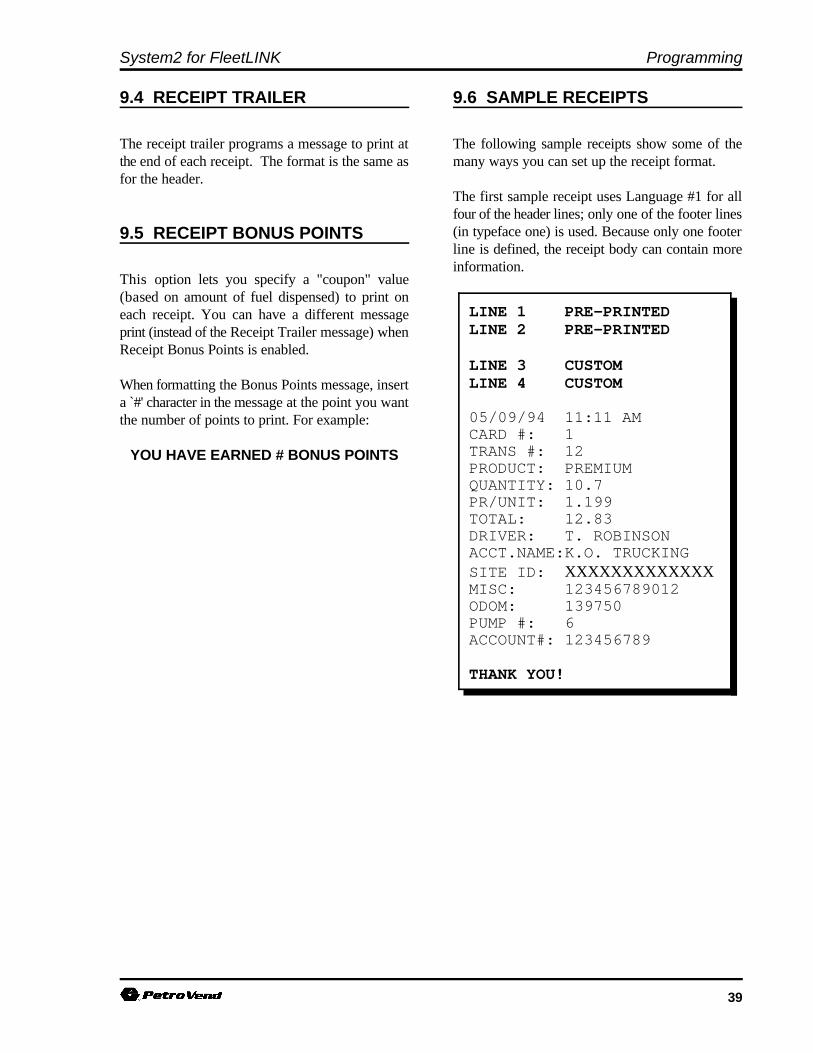
System2 for FleetLINK Programming
39
LINE 1 PRE-PRINTEDLINE 2 PRE-PRINTED
LINE 3 CUSTOMLINE 4 CUSTOM
05/09/94 11:11 AMCARD #: 1TRANS #: 12PRODUCT: PREMIUMQUANTITY: 10.7PR/UNIT: 1.199TOTAL: 12.83DRIVER: T. ROBINSONACCT.NAME:K.O. TRUCKINGSITE ID: XXXXXXXXXXXXXMISC: 123456789012ODOM: 139750PUMP #: 6ACCOUNT#: 123456789
THANK YOU!
9.4 RECEIPT TRAILER 9.6 SAMPLE RECEIPTS
The receipt trailer programs a message to print at The following sample receipts show some of thethe end of each receipt. The format is the same as many ways you can set up the receipt format.for the header.
9.5 RECEIPT BONUS POINTS
This option lets you specify a "coupon" value(based on amount of fuel dispensed) to print oneach receipt. You can have a different messageprint (instead of the Receipt Trailer message) whenReceipt Bonus Points is enabled.
When formatting the Bonus Points message, inserta `#' character in the message at the point you wantthe number of points to print. For example:
YOU HAVE EARNED # BONUS POINTS
The first sample receipt uses Language #1 for allfour of the header lines; only one of the footer lines(in typeface one) is used. Because only one footerline is defined, the receipt body can contain moreinformation.

SYSTEM2 Operator's Guide
40 10/15/97
LINE 1 PRE-PRINTED
05/10/94 11:11 AMCARD #: 1TRANS #: 12PRODUCT: PREMIUMQUANTITY: 10.7PR/UNIT: 1.199TOTAL: 12.83DRIVER: T. ROBINSONACCT. NAME:K.O. TRUCKINGSITE ID: XXXXXXXXXXXXMISC: 123456789012ODOM: 130445PUMP #: 6ACCOUNT#: 123456789
THANK YOUFOR STOPPING ATTHE WORLD'S LARGESTFUELING STATION
LINE 1 PRE-PRINTEDLINE 2 PRE-PRINTED
LINE 3 CUSTOMLINE 4 CUSTOMLINE 5 CUSTOMLINE 6 CUSTOM
05/09/94 11:11 AMCARD #: 1TRANS #: 12PRODUCT: PREMIUMQUANTITY: 10.7PR/UNIT: 1.199TOTAL: 12.83DRIVER: T. ROBINSONACCT. NAME: K.O. TRUCKINGSITE ID: XXXXXXXXXXXXMISC: 123456789012ODOM: 130445PUMP #: 6ACCOUNT#: 123456789
The following receipt uses one of the pre-printed The receipt below uses both of the pre-printedheader line (typeface one), and all four footer lines header lines and all four of the custom-defined(also typeface one). header lines. In this configuration, no footer lines
Note how the header "gives up" three lines so thatthe footer can grow. Note also how the body hasshifted upwards to accommodate the larger footer.
can be defined.

System2 for FleetLINK Programming
41
IMPORTANTYou MUST issue a DOWNLOAD commandafter altering a prompt, in order for it to bevisible.
9.7 DISPLAY (#...)
The FORMAT DISPLAY # command determinesthe prompts that appear on the FIT or OPT display.
9.7.1 Display Type Overview
The FIT or OPT display guides customers throughthe fueling process with a series of prompts. Thesystem generates default prompts (Page 42) forcertain events.
Three types of display are available:
• Standard 2x16 display shows two lines of textwith up to 16 characters per line.
• Optional 1x40 display shows one line of textwith up to 40 characters.
• Optional graphics display allows a picture tobe displayed with a prompt. The GraphicsDisplay is described in depth beginning onPage 43.
The type of display that is installed is in the StatusReport, produced with a SHOW SYSTEMcommand (Option A in the System Parametersmenu).
9.7.2 Dual Languages
Using the Dual Language feature, prompts can bedisplayed in an "alternate" language if the cardrecord for the current customer shows DualLanguage enabled.
After a card or key has been successfully read,prompts appear in Language 1 or 2, depending onhow that particular card record is configured.
See Page 64 for more information about the DualLanguage feature.
9.7.3 Special Characters
Punctuation: In addition to numbers andletters, you may include mostcharacters such as `!', `?' and`$' in the display prompts.
Beep: Add the `}' (right curlybracket) char. to any promptto have an audible tone tosound when the prompt isdisplayed. The bracket itselfdoes not appear.
9.7.4 Format Display Default
Issue a FORMAT DISPLAY DEFAULTcommand to override the physical Display TypeDIP switch settings on the PC board.
See the System2 Installation Manual for moredetails.
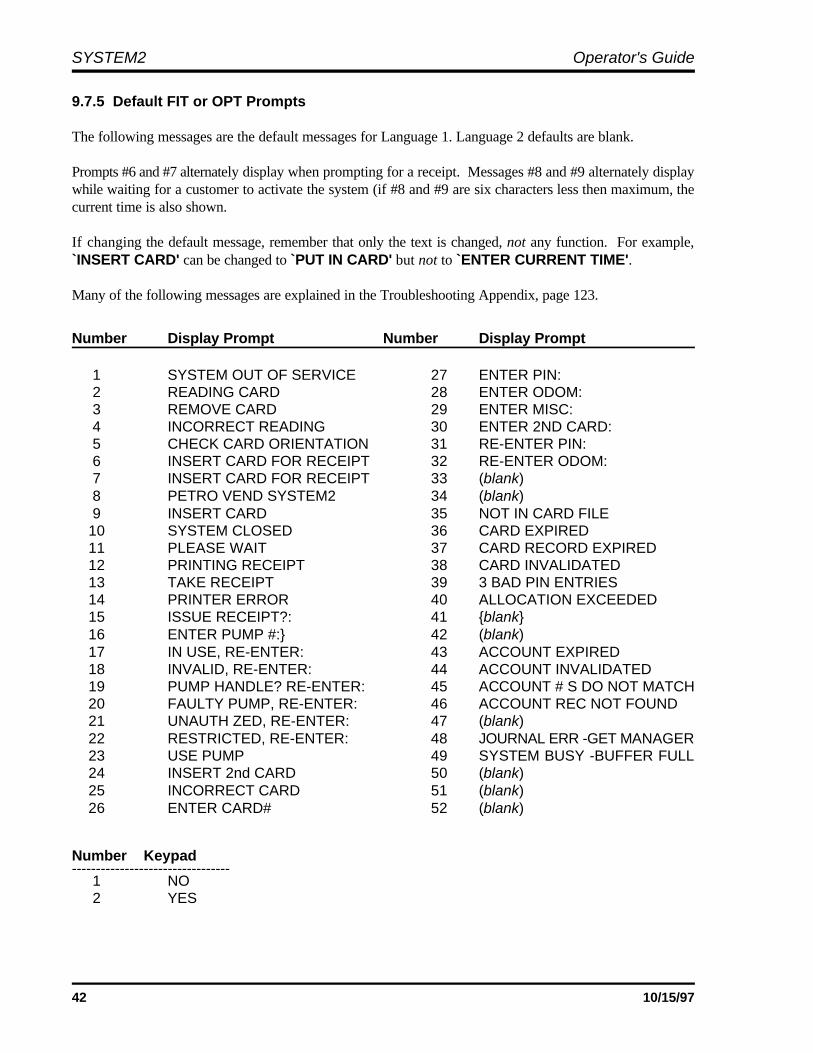
SYSTEM2 Operator's Guide
42 10/15/97
9.7.5 Default FIT or OPT Prompts
The following messages are the default messages for Language 1. Language 2 defaults are blank.
Prompts #6 and #7 alternately display when prompting for a receipt. Messages #8 and #9 alternately displaywhile waiting for a customer to activate the system (if #8 and #9 are six characters less then maximum, thecurrent time is also shown.
If changing the default message, remember that only the text is changed, not any function. For example,`INSERT CARD' can be changed to `PUT IN CARD' but not to `ENTER CURRENT TIME'.
Many of the following messages are explained in the Troubleshooting Appendix, page 123.
Number Display Prompt Number Display Prompt
1 SYSTEM OUT OF SERVICE 27 ENTER PIN: 2 READING CARD 28 ENTER ODOM: 3 REMOVE CARD 29 ENTER MISC: 4 INCORRECT READING 30 ENTER 2ND CARD: 5 CHECK CARD ORIENTATION 31 RE-ENTER PIN: 6 INSERT CARD FOR RECEIPT 32 RE-ENTER ODOM: 7 INSERT CARD FOR RECEIPT 33 (blank) 8 PETRO VEND SYSTEM2 34 (blank) 9 INSERT CARD 35 NOT IN CARD FILE 10 SYSTEM CLOSED 36 CARD EXPIRED 11 PLEASE WAIT 37 CARD RECORD EXPIRED 12 PRINTING RECEIPT 38 CARD INVALIDATED 13 TAKE RECEIPT 39 3 BAD PIN ENTRIES 14 PRINTER ERROR 40 ALLOCATION EXCEEDED 15 ISSUE RECEIPT?: 41 {blank} 16 ENTER PUMP #:} 42 (blank) 17 IN USE, RE-ENTER: 43 ACCOUNT EXPIRED 18 INVALID, RE-ENTER: 44 ACCOUNT INVALIDATED 19 PUMP HANDLE? RE-ENTER: 45 ACCOUNT # S DO NOT MATCH 20 FAULTY PUMP, RE-ENTER: 46 ACCOUNT REC NOT FOUND 21 UNAUTH ZED, RE-ENTER: 47 (blank) 22 RESTRICTED, RE-ENTER: 48 JOURNAL ERR -GET MANAGER 23 USE PUMP 49 SYSTEM BUSY -BUFFER FULL 24 INSERT 2nd CARD 50 (blank) 25 INCORRECT CARD 51 (blank) 26 ENTER CARD# 52 (blank)
Number Keypad--------------------------------- 1 NO 2 YES

System2 for FleetLINK Programming
43
9.7.6 Standard 2 x 16 Display 9.7.8 Graphics Display (Optional)
After issuing the FORMAT DISPLAY command,enter the number of the display prompt (Page 42) toedit.
If Dual Language is enabled, the system asks youto edit the display prompt for two languages.Initially, all first language prompts are in Englishand all second language prompts are blank.
After entering a prompt number, the current promptand four vertical lines appear (two for each row ofthe message). These lines represent the maximumlength of the message; the new message must fitunder the space between the lines - two rows, eachwith a maximum of 16 characters.
Upper and lower case letters can be used.
Enter the new prompt and press [ENTER] tocomplete the entry.
9.7.7 1 x 40 Display (Optional)
After issuing the FORMAT DISPLAY command,enter the number of the FIT or OPT prompt (Page42) you want to edit.
After entering a prompt number, the current promptand two vertical lines appear. These lines representthe maximum length of the message; the newprompt must fit under the space between the lines.Upper and lower case letters can be used.
Enter the new prompt and press [ENTER] tocomplete the entry.
Features
If your system has the optional Graphics Display,pictures and text (in multiple styles) can be placedon one or more lines of the display. The currenttime can also be displayed with any prompt.
Up to 80 characters can be displayed. To combinepictures with text, you add "control characters" (ona computer, CTRL characters display as ^) to textprompts. In addition to defining pictures, thesecharacters also allow you to:
• Position text on the display
• Select a text style
• Show the current time
• Clear the picture from the display.
Graphics pictures are shown on Page 46. Samplefonts and several examples of prompts withpictures and a list of control characters appear onPage 54.
The graphics codes described in this section canalso be added to the keyboard responses and to theindividual messages generated by the messagingfeature. Refer to Page 57 for more informationabout these features.
Graphic prompts are limited to 80 text characters,each control character is equal to two textcharacters. Use this prompt as an example:
`^1^Z ENTER CARD
This prompt consumes 18 characters: two for `^1'(the code that displays picture #1), two for `^Z',(the code that selects the font), and twelve for thetext ENTER CARD (including three spaces).
If Dual Language is enabled, the Graphics Displayis limited to 10 prompts of 80 characters.Additional prompts can have 40 characters for eachlanguage.
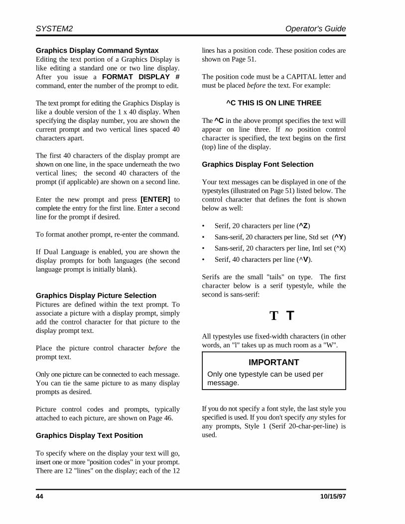
SYSTEM2 Operator's Guide
44 10/15/97
IMPORTANTOnly one typestyle can be used permessage.
Graphics Display Command SyntaxEditing the text portion of a Graphics Display islike editing a standard one or two line display.After you issue a FORMAT DISPLAY #command, enter the number of the prompt to edit.
The text prompt for editing the Graphics Display islike a double version of the 1 x 40 display. Whenspecifying the display number, you are shown the The ^C in the above prompt specifies the text willcurrent prompt and two vertical lines spaced 40 appear on line three. If no position controlcharacters apart. character is specified, the text begins on the first
The first 40 characters of the display prompt areshown on one line, in the space underneath the twovertical lines; the second 40 characters of theprompt (if applicable) are shown on a second line.
Enter the new prompt and press [ENTER] to control character that defines the font is showncomplete the entry for the first line. Enter a second below as well:line for the prompt if desired.
To format another prompt, re-enter the command.
If Dual Language is enabled, you are shown thedisplay prompts for both languages (the secondlanguage prompt is initially blank).
Graphics Display Picture SelectionPictures are defined within the text prompt. Toassociate a picture with a display prompt, simplyadd the control character for that picture to thedisplay prompt text.
Place the picture control character before theprompt text.
Only one picture can be connected to each message.You can tie the same picture to as many displayprompts as desired.
Picture control codes and prompts, typicallyattached to each picture, are shown on Page 46.
Graphics Display Text Position
To specify where on the display your text will go,insert one or more "position codes" in your prompt.There are 12 "lines" on the display; each of the 12
lines has a position code. These position codes areshown on Page 51.
The position code must be a CAPITAL letter andmust be placed before the text. For example:
^C THIS IS ON LINE THREE
(top) line of the display.
Graphics Display Font Selection
Your text messages can be displayed in one of thetypestyles (illustrated on Page 51) listed below. The
• Serif, 20 characters per line (^Z)
• Sans-serif, 20 characters per line, Std set (^Y)
• Sans-serif, 20 characters per line, Intl set (^X)
• Serif, 40 characters per line (^V).
Serifs are the small "tails" on type. The firstcharacter below is a serif typestyle, while thesecond is sans-serif:
T TAll typestyles use fixed-width characters (in otherwords, an "l" takes up as much room as a "W".
If you do not specify a font style, the last style youspecified is used. If you don't specify any styles forany prompts, Style 1 (Serif 20-char-per-line) isused.

System2 for FleetLINK Programming
45
Showing the Time of Day Display Cleaning Products
To show current time in a prompt, insert controlcharacter `^T' at the end of any display prompt.
The time is always displayed in the top right cornerof the display. It appears in the current typeface.
Inverting the Display
The graphics display normally shows darkcharacters on a light background. To invert this - toshow light characters on a dark background - use'^M' at the beginning of a prompt (see the InsertChipKey" example on Page 45).
Insert ^N to change the display back to regular"dark-on-light" mode.
Clearing the Graphics Screen
Insert the code `^0' (control zero) before theprompt text to clear the screen before displaying aprompt. This command is typically used with two-part messages; insert the command after the firstpart of the message to "erase" the screen for thesecond part.
A Graphics Display picture remains on the screenuntil one of the following occurs:
1. Another FIT or OPT prompt with a pictureis displayed
2. A prompt with the "clear screen" controlcode is displayed.
The Graphics Display has a thin anti-glare coating.DO NOT use harsh detergents or any petroleum-based solvents to clean the display!
The following products are safe for use on theSystem2 graphics display panel:
1. AR Kleener - Anti-Reflective
Shield Lens Care ProductsGolden Valley, MN(612) 542-8276
AR Kleener is available nationwide atSunglass Hut stores
2. Diamond Glaze Anti-Reflective Cleaner
Diamond Glaze, Inc.St. Paul, MN(800) 322-6644(612) 227-5560
Call the manufacturers listed above for distributorsin your area. Both are widely available in eyeglassstores or optometry clinics.

SYSTEM2 Operator's Guide
46 10/15/97
`^1' - Mag Card: Stripe Left (FIT prompts: #6, #7, #9, & #24)
`2' - Mag Card: Stripe Right (FIT prompts: #6, #7, #9, & #24)
Graphics Display Picture Control Codes & Typical Prompts
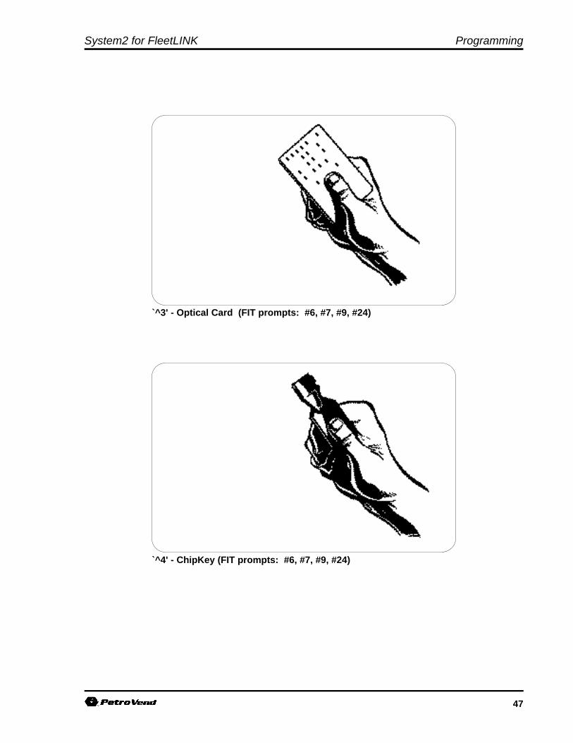
System2 for FleetLINK Programming
47
`^3' - Optical Card (FIT prompts: #6, #7, #9, #24)
`^4' - ChipKey (FIT prompts: #6, #7, #9, #24)
SYSTEM2 Operator's Guide
48 10/15/97
`^5' - Keypad Entry (FIT prompts: #26,#27,#29,#30,#31,4)
`^6' - Odometer Entry (FIT prompts: #28 & #32)
System2 for FleetLINK Programming
49
`^7' - Pump Selection (FIT prompts: #16, #20, #21, #22)
`^8' - Transaction Receipt (FIT prompt: #13)
SYSTEM2 Operator's Guide
50 10/15/97
`^9' - Wait (FIT prompt: #11)
`^:' - Petro Vend Logo (FIT prompt: #8)
System2 for FleetLINK Programming
51
!#$%&()*+,-./0123456789:<=>?@ABCDEFGHIJKLMNOPQRSTUVWXYZ
^V - Small Sans-Serif, 40 characters per line
^Y - Large Serif, 20 characters per line
Graphics Display Typestyles and Position Codes
The following screens show the available typestyles, with their matching control code. Up to 12 linesof text can be displayed for each typestyle. Position control codes (^A through ^L in FIT version1.01, ^A through ^O FIT 1.02A and over) specify where on the display the line of text appears; codesapply to all typestyles. For example, to have the prompt INSERT CARD appear at the bottom of thedisplay (perhaps under a picture), enter: ^LINSERT CARD.
SYSTEM2 Operator's Guide
52 10/15/97
^Z - Large Sans-Serif, 20 characters per line
^X - Large INTERNATIONAL Sans-Serif, 20 char per line
System2 for FleetLINK Programming
53
Graphic Code SummaryThe action of control codes in both FIT software 1.01 and 1.02A (or above) are listed below.
CODE FIT 1.01 FIT 1.02A or over
^A Position on Line 1 Position on Line 1
^B Position on Line 2 Position on Line 2
^C Position on Line 3 Position on Line 3
^D Position on Line 4 Position on Line 4
^E Position on Line 5 Position on Line 5
^F Position on Line 6 Position on Line 6
^G Position on Line 7 Position on Line 7
^H Position on Line 8 Position on Line 8
^I Position on Line 9 Position on Line 9
^J Position on Line 10 Position on Line 10
^K Position on Line 11 Position on Line 11
^L Position on Line 12 Position on Line 12
^M Invert graphics display Position on Line 13
^N Restore graphics display Position on Line 14
^O n/a Position on Line 15
^P n/a Invert graphics display
^Q n/a Restore graphics display
^T Insert Current Time Insert Current Time
^V Small Sans-Serif Font Small Sans-Serif Font
^X Large Sans-Serif Font, Int'l Large Sans-Serif Font, Int'l
^Y Large Serif Font Large Serif Font
^Z Large Sans-Serif Font, Std. Large Sans-Serif Font, Std.
^0 (zero) Clear Screen Clear Screen
SYSTEM2 Operator's Guide
54 10/15/97
^1^Y^A PETRO VEND SYSTEM 2
^4^Y^A INSERT CHIPKEY
Graphics Display ExamplesThe following displays result from the text/control code strings located under each.

System2 for FleetLINK Programming
55
^1^Z^I PETRO VEND ^J SYSTEM 2
^0^Y^E CHECK CARD ^F ORIENTATION
SYSTEM2 Operator's Guide
56 10/15/97
^4^Y^I INSERT ^J CHIPKEY
^1^Y^T^I PETRO VEND ^J SYSTEM 2
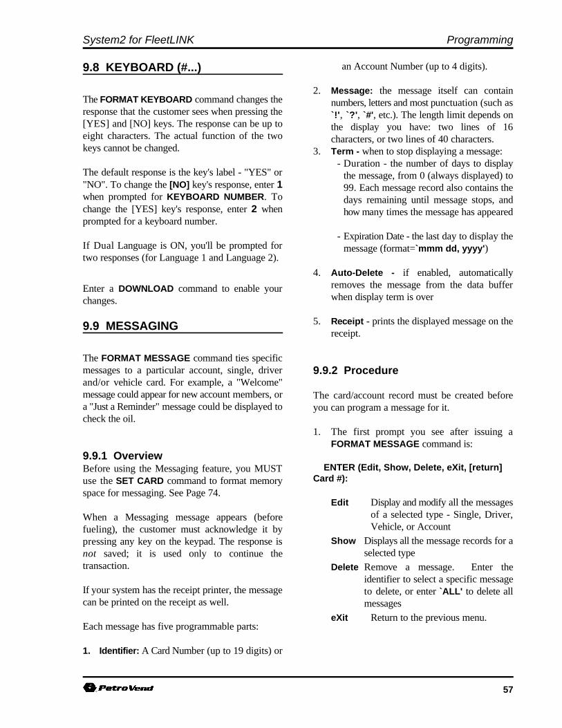
System2 for FleetLINK Programming
57
9.8 KEYBOARD (#...)
The FORMAT KEYBOARD command changes theresponse that the customer sees when pressing the[YES] and [NO] keys. The response can be up toeight characters. The actual function of the twokeys cannot be changed.
The default response is the key's label - "YES" or"NO". To change the [NO] key's response, enter 1when prompted for KEYBOARD NUMBER. Tochange the [YES] key's response, enter 2 whenprompted for a keyboard number.
If Dual Language is ON, you'll be prompted fortwo responses (for Language 1 and Language 2).
Enter a DOWNLOAD command to enable yourchanges.
9.9 MESSAGING
The FORMAT MESSAGE command ties specificmessages to a particular account, single, driverand/or vehicle card. For example, a "Welcome"message could appear for new account members, ora "Just a Reminder" message could be displayed tocheck the oil.
9.9.1 OverviewBefore using the Messaging feature, you MUSTuse the SET CARD command to format memoryspace for messaging. See Page 74.
When a Messaging message appears (beforefueling), the customer must acknowledge it bypressing any key on the keypad. The response isnot saved; it is used only to continue thetransaction.
If your system has the receipt printer, the messagecan be printed on the receipt as well.
Each message has five programmable parts:
1. Identifier: A Card Number (up to 19 digits) or
an Account Number (up to 4 digits).
2. Message: the message itself can containnumbers, letters and most punctuation (such as`!', `?', `#', etc.). The length limit depends onthe display you have: two lines of 16characters, or two lines of 40 characters.
3. Term - when to stop displaying a message:- Duration - the number of days to display
the message, from 0 (always displayed) to99. Each message record also contains thedays remaining until message stops, andhow many times the message has appeared
- Expiration Date - the last day to display themessage (format=`mmm dd, yyyy')
4. Auto-Delete - if enabled, automaticallyremoves the message from the data bufferwhen display term is over
5. Receipt - prints the displayed message on thereceipt.
9.9.2 Procedure
The card/account record must be created beforeyou can program a message for it.
1. The first prompt you see after issuing aFORMAT MESSAGE command is:
ENTER (Edit, Show, Delete, eXit, [return]Card #):
Edit Display and modify all the messagesof a selected type - Single, Driver,Vehicle, or Account
Show Displays all the message records for aselected type
Delete Remove a message. Enter theidentifier to select a specific messageto delete, or enter `ALL' to delete allmessages
eXit Return to the previous menu.
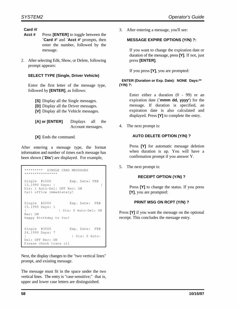
SYSTEM2 Operator's Guide
58 10/15/97
********* SINGLE CARD MESSAGES****************
Single #1000 Exp. Date: FEB 13,1990 Days: | |Dis: 1 Auto-Del: OFF Rec: ONCall office immediately!
Single #2000 Exp. Date: FEB15,1990 Days: 1| | Dis: 0 Auto-Del: ONRec: ONHappy Birthday to You!
Single #3000 Exp. Date: FEB24,1990 Days: 7| | Dis: 0 Auto-Del: OFF Rec: ONPlease check trans oil
Card #/Acct # Press [ENTER] to toggle between the
`Card #' and `Acct #' prompts, thenenter the number, followed by themessage. If you want to change the expiration date or
2. After selecting Edit, Show, or Delete, following press [ENTER].prompt appears:
SELECT TYPE (Single, Driver Vehicle)
Enter the first letter of the message type,followed by [ENTER], as follows:
[S] Display all the Single messages.[D] Display all the Driver messages.[V] Display all the Vehicle messages.
[A] or [ENTER] Displays all theAccount messages.
[X] Ends the command.
After entering a message type, the formatinformation and number of times each message hasbeen shown (`Dis') are displayed. For example,
Next, the display changes to the "two vertical lines"prompt, and existing message.
The message must fit in the space under the twovertical lines. The entry is "case-sensitive;" that is,upper and lower case letters are distinguished.
3. After entering a message, you'll see:
MESSAGE EXPIRE OPTIONS (Y/N) ?:
duration of the message, press [Y]. If not, just
If you press [Y], you are prompted:
ENTER (Duration or Exp. Date): NONE Days:**(Y/N) ?:
Enter either a duration (0 - 99) or anexpiration date (`mmm dd, yyyy') for themessage. If duration is specified, anexpiration date is also calculated anddisplayed. Press [Y] to complete the entry.
4. The next prompt is:
AUTO DELETE OPTION (Y/N) ?
Press [Y] for automatic message deletionwhen duration is up. You will have aconfirmation prompt if you answer Y.
5. The next prompt is:
RECEIPT OPTION (Y/N) ?
Press [Y] to change the status. If you press[Y], you are prompted:
PRINT MSG ON RCPT (Y/N) ?
Press [Y] if you want the message on the optionalreceipt. This concludes the message entry.

System2 for FleetLINK Programming
59
9.10 DATE
The FORMAT DATE command displays thefollowing prompt:
ENTER (Show, Order, sEparator, eXit, Month#):
9.10.1 Procedure
Press the first letter of one of the options (below) toselect that option.
Show Displays current data.
Order Two "orders" are available, eachassociated with a code number: (1)"month day year" and (2) "day monthyear"). You are prompted: DATEORDER CODE FOR LANGUAGE 1:enter `1' for month first or `2' for dayfirst (see Section 9.10.3.
If the dual language feature is enabled,you are prompted a second time for thedate code. You can specify a differentcode for each language.
sEparator Select the two field separatorcharacters
eXit Returns you to the previous menu
month # Changes the label(s) for the selectedmonth (see the following section).
9.10.2 Month Labeling
The default date month labels are listed below:
MONTH # Language 1 Language 2
1 JAN 01
2 FEB 02
3 MAR 03
4 APR 04
5 MAY 05
6 JUN 06
7 JUL 07
8 AUG 08
9 SEP 09
10 OCT 10
11 NOV 11
12 DEC 12
9.10.3 Date Order
Choose between day first (24 JAN, 1994) or monthfirst (JAN 24, 1994) for the date order. Language1 default is month first, while Language 2 defaultis day first.
9.10.4 Date Separators
Date separators distinguish the parts of the date;any printable ASCII character can be used.
Language 1 default is a space and a commabetween the day (or month) and the year (example,DEC 30, 1993). Language 2's default is two dashes(for example, 30-12-1993).

SYSTEM2 Operator's Guide
60 10/15/97
Notes:
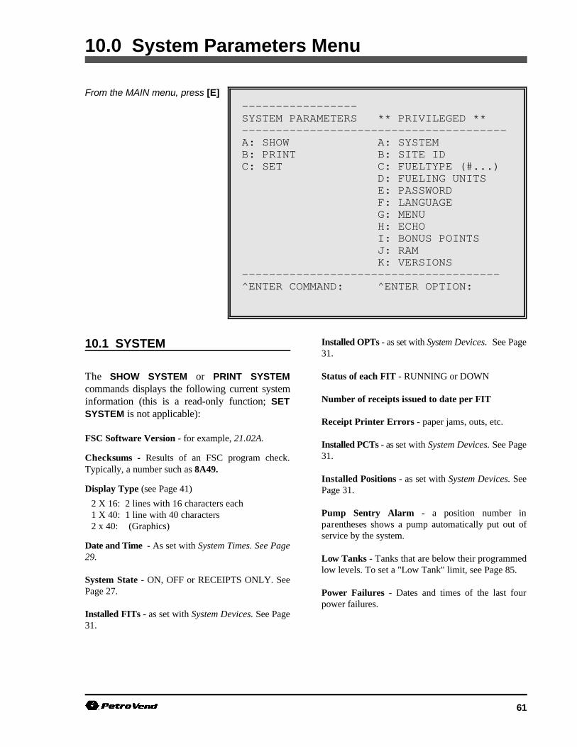
61
-----------------SYSTEM PARAMETERS ** PRIVILEGED **--------------------------------------- A: SHOW A: SYSTEMB: PRINT B: SITE IDC: SET C: FUELTYPE (#...)
D: FUELING UNITSE: PASSWORDF: LANGUAGEG: MENUH: ECHOI: BONUS POINTSJ: RAMK: VERSIONS
-------------------------------------- ^ENTER COMMAND: ^ENTER OPTION:
10.0 System Parameters Menu
From the MAIN menu, press [E]
10.1 SYSTEM
The SHOW SYSTEM or PRINT SYSTEMcommands displays the following current systeminformation (this is a read-only function; SETSYSTEM is not applicable):
FSC Software Version - for example, 21.02A.
Checksums - Results of an FSC program check.Typically, a number such as 8A49.
Display Type (see Page 41) 2 X 16: 2 lines with 16 characters each1 X 40: 1 line with 40 characters2 x 40: (Graphics)
Date and Time - As set with System Times. See Page29.
System State - ON, OFF or RECEIPTS ONLY. SeePage 27.
Installed FITs - as set with System Devices. See Page31.
Installed OPTs - as set with System Devices. See Page31.
Status of each FIT - RUNNING or DOWN
Number of receipts issued to date per FIT
Receipt Printer Errors - paper jams, outs, etc.
Installed PCTs - as set with System Devices. See Page31.
Installed Positions - as set with System Devices. SeePage 31.
Pump Sentry Alarm - a position number inparentheses shows a pump automatically put out ofservice by the system.
Low Tanks - Tanks that are below their programmedlow levels. To set a "Low Tank" limit, see Page 85.
Power Failures - Dates and times of the last fourpower failures.
SYSTEM2 Operator's Guide
62 10/15/97
IMPORTANTThe current fuel price is recorded for everytransaction. Changing the fuel price doesnot affect completed transactions.
10.2 SITE I.D.
Use the SET SITE command to enter a12-character code to give a site a unique name. Thesystem defaults a site "name" of"XXXXXXXXXXXX".
This code can be printed on receipts, and is usedduring backup and restore operations with anexternal computer. Your site ID must be exactly 12characters long. It can contain spaces, though thefirst character cannot be a space.
10.3 FUELTYPES (#...)
Fuel units (gallons, liters, etc), prices, and namescan be assigned for up to 16 different products.Each product is assigned a code number, which youassign during PCT configuration. Fueltype data canbe assigned individually to each pump or hose.
The following are the system default names for the16 products. Each product has a default "price-per-unit" of $1.00. The "unit" default is gallons; thiscan be changed using the SET FUELING UNITScommand, Page 63.
CODE DEFAULT PRODUCT
1 Unleaded
2 Premium
3 Regular
4 Marked Fuel
5 #1 Diesel
6 #2 Diesel
7 Gasohol
8 Alcohol
9 Propane
10 LPG
11 Lubeoil 1
12 Lubeoil 2
13 Trans Oil
14 Coolant
15 Water
16 Air
To change a fuel type:
1. Issue the SET FUELTYPE # command, where`#' is the code number (1-16). The first promptis:
ENTER FUELING UNIT CODE (1-3):
A fueling unit (gallon, litre, quart) must bespecified with the SET FUELING UNITScommand (next section). Default code is "1".The default for code 1 is GALLON.
2. The next prompt is:
CHANGE PRICE (Y/N)?
To keep the price the same, press [ENTER]. Ifyou want to change price per unit, enter [Y] todisplay the next prompt:
ENTER PRICE PER GALLON
Default price is $1.00 per unit. Price can bespecified to a tenth of a cent; for example,`$1.059'. A price of `$0.000' can be specifiedfor non-retail sites.
3. The next prompt is:CHANGE PRODUCT NAME (Y/N)?
To keep the name the same. press [ENTER].To change it, press [Y] to display the nextprompt:
ENTER FUELTYPE 1:
Names can be up to ten characters long. Typea name, and press [ENTER]. Change otherfueltype codes as desired.

System2 for FleetLINK Programming
63
IMPORTANTIf all you see is a dollar sign prompt ($),Restricted mode is ON. To turn this modeOFF, use the SET PASSWORD command(Privileged mode) to turn it OFF.
10.4 FUELING UNITS
Three different unit-of-measure labels can beconnected to product types (previous section).These are simply labels - no conversion is done.
The default labels, and their "Fueling Unit Codes",are:
(1) gallon (2) liter (3) quart
The code numbers (1, 2, or 3) are input at theFUELING UNIT CODES prompt during the SETFUELTYPES procedure (Page 62).
To change the default values:
1. Enter the SET FUELING UNITS command.You are then prompted for each of the threelabels:
ENTER FUELING UNIT 1:ENTER FUELING UNIT 2:ENTER FUELING UNIT 3:
To leave a unit the same, just press [ENTER].
2. To change a unit, enter a label of up to 10characters and press [ENTER].
10.5 PASSWORD
There are three modes of operation for SYSTEM2:(1) normal, (2) privileged and (3) restricted.
Normal - Most SHOW and PRINTcommands are useable in normalmode. The screen prompt (in non-menu mode) is >.
Privileged - Most SET or FORMATcommands require privilegedaccess. The screen prompt is P>.
Restricted -This mode, signified by a $ prompt,requires a password be entered for any screendisplay to be visible. This mode is off until youenable it with SET PASSWORD.
The SET PASSWORD command changes thepasswords for the Privileged and Restricted modes,and enables or disables the Restricted mode.
Your unit comes from the factory with allpasswords set as HELLO, and the Restricted modeOFF. Passwords do not have to be changed, or theRestricted mode enabled, in order for SYSTEM2to operate.
This command is also used to change the Modempassword - see Page 109.
To change any or all passwords:
1. Enter SET PASSWORD. The system promptsfirst for the MAIN (Privileged mode)password.
2. Enter up to six characters for the mainpassword (or press [ENTER] to retain the oldpassword). There is no difference betweenupper and lower case letters. The system nowprompts you for the MODEM password.
3. Enter a new Modem password or press[ENTER] to retain the old password and moveto the next prompt.
4. After entering the modem password, the nextprompt enables or disables the Restrictedmode:
`SHOW' PASSWORD OPTIONS (Y/N) ?
SYSTEM2 Operator's Guide
64 10/15/97
5. If you don't want to use the Restricted mode (it menus, you typically type the command as itis disabled by default), press [ENTER] to skip. appears on the menu. For example, for the menuIf you press [Y]: ON/OFF function, the menu lists SET on the left
ENABLE SHOW PASSWORD (Y/N) ?
6. Press [Y] or [N] as appropriate. If you enter[Y], you are prompted to enter a new showpassword.
10.6 LANGUAGE
The Dual Language feature allows SYSTEM2 tobe "bi-lingual" to a certain degree - to display orprint two different languages.
Use the privileged SET LANGUAGE command toturn the Dual Language ON or OFF. Simplyanswer [Y] or [N] to the ENABLE DUALLANGUAGE (Y/N) prompt, and press [ENTER].
A Language Type is programmed into each cardrecord. When the card is read, the FIT displaylanguage changes to the programmed language.Optional receipts also print out in the specifiedlanguage.
To program bilingual cards, use the SET CARDcommand (see Page 74). The display prompts areexplained in detail on Page 41. Receipts areexplained beginning on Page 37.
Certain prompts cannot be defined for a secondlanguage - prompts #2, 3, 4, 5, 6, 7, 8, 9, 24, 25,26 and 35 (Page 42) are displayed before a card orkey has been read, these prompts should not beprogrammed for a second language.
10.7 MENU
The SET MENU command turns the system'smenus ON or OFF. When menus are OFF,commands must be entered at the prompts (>, P>.).
Menus are shown on the first page of each sectionof this manual. When issuing commands without
and MENU on the right (SET MENU).
Menus are ON by system default, and appearautomatically at system power-up.
10.8 ECHO
During programming, the FSC sends back (echos)every character it receives from the terminal if echois enabled. Echo must be ON in order for you to seethe characters as you type them into the terminal.
Echo is typically disabled with the SET ECHOcommand only when interfacing to an externalcomputer. Refer to Page 111 for external computeroperation.
10.9 BONUS POINTS
The SET BONUS POINTS command allows you tospecify a "coupon" value (based on the amount offuel dispensed) to be printed on each receipt. ABonus Points message can also be specified.
For example, bonus points can be awarded tocustomers as credit toward using a local car washfacility.
10.10 RAM
Initially configuring your SYSTEM2 requires youdefine the size of the system memory with the SETRAM command.
The card file and transaction records are stored inRAM chips on the FSC board. The number ofRAM chips on your FSC board depends on theamount of RAM you ordered.
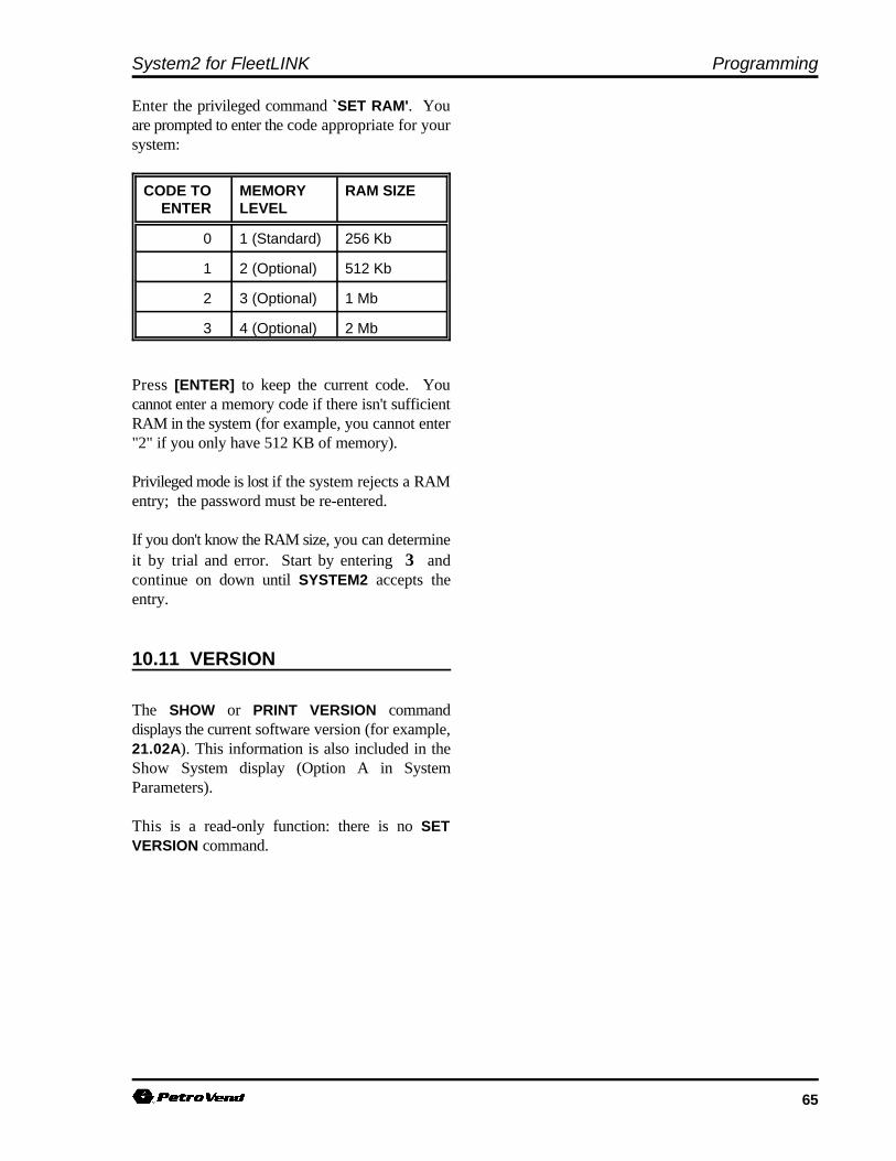
System2 for FleetLINK Programming
65
Enter the privileged command `SET RAM'. Youare prompted to enter the code appropriate for yoursystem:
CODE TO MEMORY RAM SIZEENTER LEVEL
0 1 (Standard) 256 Kb
1 2 (Optional) 512 Kb
2 3 (Optional) 1 Mb
3 4 (Optional) 2 Mb
Press [ENTER] to keep the current code. Youcannot enter a memory code if there isn't sufficientRAM in the system (for example, you cannot enter"2" if you only have 512 KB of memory).
Privileged mode is lost if the system rejects a RAMentry; the password must be re-entered.
If you don't know the RAM size, you can determineit by trial and error. Start by entering 3 andcontinue on down until SYSTEM2 accepts theentry.
10.11 VERSION
The SHOW or PRINT VERSION commanddisplays the current software version (for example,21.02A). This information is also included in theShow System display (Option A in SystemParameters).
This is a read-only function: there is no SETVERSION command.

SYSTEM2 Operator's Guide
66 10/15/97
Notes:
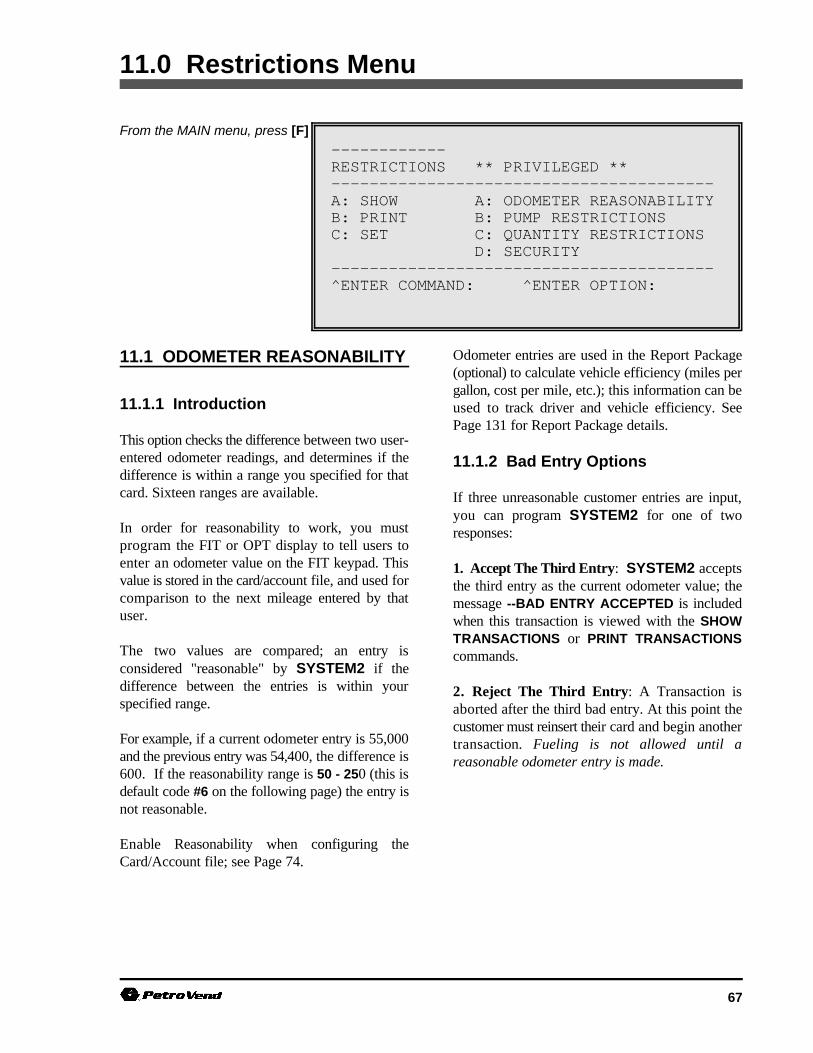
67
------------RESTRICTIONS ** PRIVILEGED **----------------------------------------A: SHOW A: ODOMETER REASONABILITYB: PRINT B: PUMP RESTRICTIONSC: SET C: QUANTITY RESTRICTIONS
D: SECURITY----------------------------------------^ENTER COMMAND: ^ENTER OPTION:
11.0 Restrictions Menu
From the MAIN menu, press [F]
11.1 ODOMETER REASONABILITY
11.1.1 Introduction
This option checks the difference between two user-entered odometer readings, and determines if thedifference is within a range you specified for thatcard. Sixteen ranges are available.
In order for reasonability to work, you mustprogram the FIT or OPT display to tell users toenter an odometer value on the FIT keypad. Thisvalue is stored in the card/account file, and used forcomparison to the next mileage entered by thatuser.
The two values are compared; an entry isconsidered "reasonable" by SYSTEM2 if thedifference between the entries is within yourspecified range.
For example, if a current odometer entry is 55,000and the previous entry was 54,400, the difference is600. If the reasonability range is 50 - 250 (this isdefault code #6 on the following page) the entry isnot reasonable.
Enable Reasonability when configuring theCard/Account file; see Page 74.
Odometer entries are used in the Report Package(optional) to calculate vehicle efficiency (miles pergallon, cost per mile, etc.); this information can beused to track driver and vehicle efficiency. SeePage 131 for Report Package details.
11.1.2 Bad Entry Options
If three unreasonable customer entries are input,you can program SYSTEM2 for one of tworesponses:
1. Accept The Third Entry: SYSTEM2 acceptsthe third entry as the current odometer value; themessage --BAD ENTRY ACCEPTED is includedwhen this transaction is viewed with the SHOWTRANSACTIONS or PRINT TRANSACTIONScommands.
2. Reject The Third Entry: A Transaction isaborted after the third bad entry. At this point thecustomer must reinsert their card and begin anothertransaction. Fueling is not allowed until areasonable odometer entry is made.
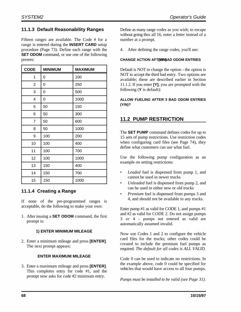
SYSTEM2 Operator's Guide
68 10/15/97
11.1.3 Default Reasonability Ranges Define as many range codes as you wish; to escape
Fifteen ranges are available. The Code # for a number at a prompt.range is entered during the INSERT CARD setupprocedure (Page 73). Define each range with the 4. After defining the range codes, you'll see:SET ODOM command, or use one of the followingpresets: CHANGE ACTION AFTER BAD ODOM ENTRIES (Y/N)
CODE MINIMUM MAXIMUM
1 0 100
2 0 250
3 0 500
4 0 1000
5 50 150
6 50 300
7 50 600
8 50 1000
9 100 200
10 100 400
11 100 700
12 100 1000
13 150 400
14 150 700
15 150 1000
11.1.4 Creating a Range
If none of the pre-programmed ranges isacceptable, do the following to make your own:
1. After issuing a SET ODOM command, the firstprompt is:
1) ENTER MINIMUM MILEAGE
2. Enter a minimum mileage and press [ENTER].The next prompt appears:
ENTER MAXIMUM MILEAGE
3. Enter a maximum mileage and press [ENTER].This completes entry for code #1, and theprompt now asks for code #2 minimum entry.
without going thru all 16, enter a letter instead of a
Default is NOT to change the option - the option isNOT to accept the third bad entry. Two options areavailable; these are described earlier in Section11.1.2. If you enter [Y], you are prompted with thefollowing (Y is default):
ALLOW FUELING AFTER 3 BAD ODOM ENTRIES(Y/N)?
11.2 PUMP RESTRICTION
The SET PUMP command defines codes for up to15 sets of pump restrictions. Use restriction codeswhen configuring card files (see Page 74), theydefine what customers can use what fuel.
Use the following pump configuration as anexample on setting restrictions:
• Leaded fuel is dispensed from pump 1, andcannot be used in newer trucks
• Unleaded fuel is dispensed from pump 2, andcan be used in either new or old trucks
• Premium fuel is dispensed from pumps 3 and4, and should not be available to any trucks.
Enter pump #1 as valid for CODE 1, and pumps #1and #2 as valid for CODE 2. Do not assign pumps3 or 4 - pumps not entered as valid areautomatically assumed invalid.
Now use Codes 1 and 2 to configure the vehiclecard files for the trucks; other codes could becreated to include the premium fuel pumps asrequired. The default for all codes is ALL VALID.
Code 0 can be used to indicate no restrictions. Inthe example above, code 0 could be specified forvehicles that would have access to all four pumps.
Pumps must be installed to be valid (see Page 31).
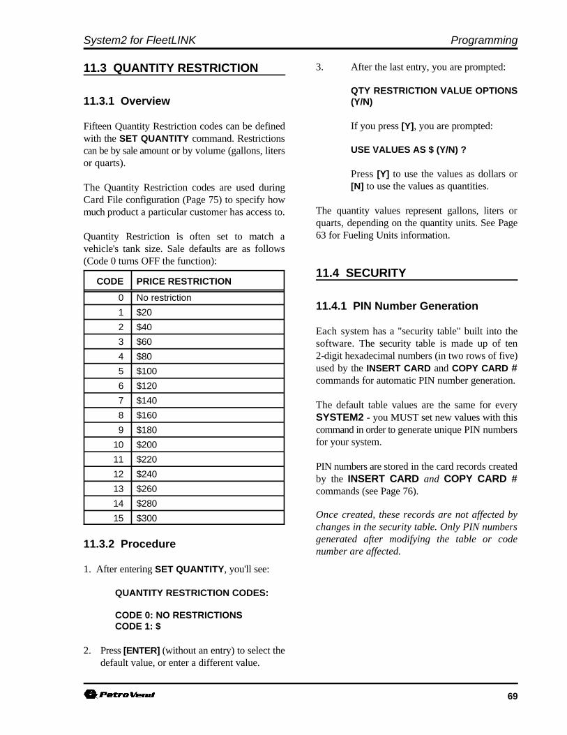
System2 for FleetLINK Programming
69
11.3 QUANTITY RESTRICTION
11.3.1 Overview
Fifteen Quantity Restriction codes can be definedwith the SET QUANTITY command. Restrictionscan be by sale amount or by volume (gallons, litersor quarts).
The Quantity Restriction codes are used duringCard File configuration (Page 75) to specify howmuch product a particular customer has access to.
Quantity Restriction is often set to match avehicle's tank size. Sale defaults are as follows(Code 0 turns OFF the function):
CODE PRICE RESTRICTION
0 No restriction
1 $20
2 $40
3 $60
4 $80
5 $100
6 $120
7 $140
8 $160
9 $180
10 $200
11 $220
12 $240
13 $260
14 $280
15 $300
11.3.2 Procedure
1. After entering SET QUANTITY, you'll see:
QUANTITY RESTRICTION CODES:
CODE 0: NO RESTRICTIONSCODE 1: $
2. Press [ENTER] (without an entry) to select thedefault value, or enter a different value.
3. After the last entry, you are prompted:
QTY RESTRICTION VALUE OPTIONS(Y/N)
If you press [Y], you are prompted:
USE VALUES AS $ (Y/N) ?
Press [Y] to use the values as dollars or[N] to use the values as quantities.
The quantity values represent gallons, liters orquarts, depending on the quantity units. See Page63 for Fueling Units information.
11.4 SECURITY
11.4.1 PIN Number Generation
Each system has a "security table" built into thesoftware. The security table is made up of ten2-digit hexadecimal numbers (in two rows of five)used by the INSERT CARD and COPY CARD #commands for automatic PIN number generation.
The default table values are the same for everySYSTEM2 - you MUST set new values with thiscommand in order to generate unique PIN numbersfor your system.
PIN numbers are stored in the card records createdby the INSERT CARD and COPY CARD #commands (see Page 76).
Once created, these records are not affected bychanges in the security table. Only PIN numbersgenerated after modifying the table or codenumber are affected.
SYSTEM2 Operator's Guide
70 10/15/97
IMPORTANTBe sure to record your Security Tablenumbers on the worksheet (Appendix A)!If you are reconfiguring your system, orwish to generate PIN numbers to matchanother SYSTEM2, the row and securitycode numbers must match your originalentries!
11.4.2 Procedure
After entering the SET SEC command, you areprompted with the current value of ROW 1 (thesystem defaults are shown):
ROW 1: 01 23 45 67 89
1. Enter five 2-digit hex numbers, pressing the[ENTER] key after each. PIN numbers are stored in the card records created
Hex numbers include the decimal numbers 0 to commands. Once created, these records are not9 and the letters A to F. affected by changes in the security table. Only PIN
The entries should be as random as possible to code number are affected.maximize the uniqueness of the PIN numbersthat will be generated from this table. Forexample, `A0 E9 83 DD 1C' is good, but `12 1212 12 12' is not.
2. After the fifth entry, you are prompted for thesecond row (ROW 2) in the same way as thefirst.
3. Again, enter five different 2-digit hex numbers.
4. After entering the last digit in row 2, you areprompted with:
SECURITY CODE: 00ENTER CODE:
The Security Code (system default is 00) providesan additional degree of randomness to the securitytable. Changing only the security code causesdifferent PIN numbers to be generated from thesame security table. Enter any 2-digit hex number(except `00') for this code.
K-3000 Users: To generate PIN numberscompatible with a K-3000 system, enter the firstfive 2-digit security numbers from the K-3000System Data Sheet for Row 1. Enter the next five2-digit security numbers for Row 2.
DO NOT use the last six numbers listed on the K-3000 data sheet. Enter `00' for the security code.
by the INSERT CARD and COPY CARD #
numbers generated after modifying the table or

71
--------------CARDS/ACCOUNTS ** PRIVILEGED **-------------------------------------A: SHOW A: CARD (#...)B: PRINT B: CARD SUMMARY
C: CARD ACCOUNTD: ACCOUNT (#...)
-------------------------------------C: INSERT E: CARDD: DELETE F: ACCOUNTE: EDIT-------------------------------------F: SET G: CARD-------------------------------------G: COPY H: CARD #...-------------------------------------H: SORT-------------------------------------^ENTER COMMAND: ^ENTER OPTION:
12.0 Cards/Accounts Menu
From MAIN menu, press [G]
12.1 INTRODUCTION
The Cards/Accounts menu lets you view or printcards or account summaries, remove, add, orchange cards within an account, remove add orchange entire accounts, copy cards, and sort cardsor accounts.
Before using most of the Card/Account features,you must first issue a SET CARD command, andthen, from that submenu, do the following twothings:
1. You must "reserve" memory space in the systemfor the cards and accounts - use the 1.)SPECIFY CARD/ACCOUNT BUFFER SIZEcommand (in the SET CARD submenu)command does this.
The Messaging feature (Page 57) also requiresyou define memory space using SET CARD.
2. After specifying the Card/Account Buffer Size,you must use 2.) DEFINE CARD/ACCOUNTRECORD (also in the SET CARD submenu) toselect the items to be included for each recordin the file.
Both tasks must be done before any cards can beprogrammed.
The remaining options in the SET CARD submenuare used to manipulate transaction data for thecard/account files, and can be used any time.
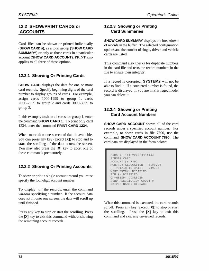
SYSTEM2 Operator's Guide
72 10/15/97
CARD #: 1111222233334444SINGLE CARDACCOUNT #: 7890MONTHLY ALLOCATION: $100.00-- TOTALS TO DATE: $39.85MISC ENTRY: DISABLEDPIN #: DISABLEDODOMETER: DISABLEDPUMP RESTRICTION CODE: 0DRIVER NAME: RICHARD
12.2 SHOW/PRINT CARDS or ACCOUNTS
Card files can be shown or printed individually(SHOW CARD #), as a total group (SHOW CARDSUMMARY) or only as those cards in a particularaccount (SHOW CARD ACCOUNT). PRINT alsoapplies to all three of these options.
12.2.1 Showing Or Printing Cards
SHOW CARD displays the data for one or morecard records. Specify beginning digits of the cardnumber to display groups of cards. For example,assign cards 1000-1999 to group 1, cards2000-2999 to group 2 and cards 3000-3999 togroup 3.
In this example, to show all cards for group 1, enterthe command SHOW CARD 1. To print only card1234, enter the command PRINT CARD 1234.
When more than one screen of data is available,you can press any key (except [X]) to stop and tostart the scrolling of the data across the screen.You may also press the [X] key to abort one ofthese commands prematurely.
12.2.2 Showing Or Printing Accounts
To show or print a single account record you mustspecify the four-digit account number.
To display all the records, enter the commandwithout specifying a number. If the account datadoes not fit onto one screen, the data will scroll upuntil finished.
Press any key to stop or start the scrolling. Pressthe [X] key to exit this command without showingthe remaining account records.
12.2.3 Showing or PrintingCard Summaries
SHOW CARD SUMMARY displays the breakdownof records in the buffer. The selected configurationoptions and the number of single, driver and vehiclecards are listed.
This command also checks for duplicate numbersin the card file and tests the record numbers in thefile to ensure their integrity.
If a record is corrupted, SYSTEM2 will not beable to find it. If a corrupted number is found, therecord is displayed. If you are in Privileged mode,you can delete it.
12.2.4 Showing or PrintingCard Account Numbers
SHOW CARD ACCOUNT shows all of the cardrecords under a specified account number. Forexample, to show cards in file 7890, use thecommand SHOW CARD ACCOUNT 7890. Thecard data are displayed in the form below:
When this command is executed, the card recordsscroll. Press any key (except [X]) to stop or startthe scrolling. Press the [X] key to exit thiscommand and skip any unviewed records.

System2 for FleetLINK Programming
73
12.3 INSERT/DELETE/EDIT Valid? Specify if the card record is valid. ThisCARD or ACCOUNT allows you to create an invalid card record now,
These commands are used to program individualcards and accounts for the system. Cards andaccounts must exist prior to using these commands.
12.3.1 INSERT Card or Account
The INSERT CARD or ACCOUNT commands onlyprompt for entries if memory space is available.
Inserting Cards
Petro Vend magnetic cards require 16-digitnumbers. Optically-read cards require 10 digitnumbers.
The first four digits for both types of card must beone of the network numbers for your system. Thenetwork numbers are listed on your system's datasheet; most systems have just one network number.
Cardless Records. A cardless "card" is not aphysical card, but simply a number entered at theSYSTEM2 keypad.
The following apply to cardless cards:
C A cardless record can be up to eight digits long-the network number does NOT have to be aprefix
C The FIT must be set up for cardless operation.FIT configuration is explained on Page 31
C The PIN entries feature should be enabled forcardless operation.
Dual-Language. If enabled, you are prompted toselect the first or second language for the card.(Single and Driver cards only).
PIN Number. If enabled, you are prompted forautomatic PIN number generator. Enable this fieldto have SYSTEM2 generate the PIN numbers;card numbers must be five or more digits long.
Card Type. Single, Driver or Vehicle must bespecified for each card record.
and activate it at a later date.
Misc Entry. This option allows the fueler to enterup to 10 numbers (such as a job number) that willbe included in the transaction record.
The remainder of the prompts are described in theSET CARD command. Some or all of the specifiedparts can be selected for each record.
Inserting Accounts
The system prompts for an account number,expiration date, validity, discount, monthly anddaily allocations, pump and quantity restrictionsand an account name (as explained in SET CARD).
C If you enter less than four digits for an accountnumber, leading zeros are added. Forexample, account 12 is defined as 0012
C Only the original price is shown (or printed).The discounted price(s) are displayed onlywhen generating reports with the ReportPackage
C In Dual-card operation, driver and vehiclecards must be assigned to the same accountnumber. To allow access to vehicle(s) fromany account, you can assign the vehicle(s) toaccount 0000.
As an example, say a company has cars assigned toeach department, each with its own accountnumber. The company also has a van that is neededby everyone. By assigning the vehicle card for thevan to account 0000, members of all departments(or accounts) can use the van.
12.3.2 DELETE Card or Account
DELETE CARD eliminates an individual cardrecord; you are prompted for the card number.Enter the number and press [ENTER] to delete thecard record.
DELETE ACCOUNT eliminates an account record;you are prompted for the account number. Enter thenumber and press [ENTER] to delete the account.
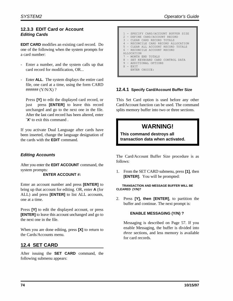
SYSTEM2 Operator's Guide
74 10/15/97
1 - SPECIFY CARD/ACCOUNT BUFFER SIZE2 - DEFINE CARD/ACCOUNT RECORD3 - CLEAR CARD RECORD TOTALS 4 - RECONCILE CARD RECORD ALLOCATION5 - CLEAR ALL ACCOUNT RECORD TOTALS6 - RECONCILE ACCOUNT RECORDALLOCATION7 - MONTH END TOTALS8 - SET KEYBOARD CARD CONTROL DATA9 - ADDITIONAL OPTIONSX - EXIT ENTER CHOICE:
WARNING!This command destroys alltransaction data when activated.
12.3.3 EDIT Card or AccountEditing Cards
EDIT CARD modifies an existing card record. Doone of the following when the system prompts fora card number:
- Enter a number, and the system calls up thatcard record for modification, OR...
- Enter ALL. The system displays the entire cardfile, one card at a time, using the form CARD###### (Y/N/X) ? 12.4.1 Specify Card/Account Buffer Size
Press [Y] to edit the displayed card record, orjust press [ENTER] to leave this recordunchanged and go to the next one in the file.After the last card record has been altered, enter`X' to exit this command .
If you activate Dual Language after cards havebeen inserted, change the language designation ofthe cards with the EDIT command.
Editing Accounts
After you enter the EDIT ACCOUNT command, thesystem prompts:
ENTER ACCOUNT #:
Enter an account number and press [ENTER] tobring up that account for editing. OR, enter A (forALL) and press [ENTER] to list ALL accounts,one at a time.
Press [Y] to edit the displayed account, or press[ENTER] to leave this account unchanged and go tothe next one in the file.
When you are done editing, press [X] to return tothe Cards/Accounts menu.
12.4 SET CARD
After issuing the SET CARD command, thefollowing submenu appears:
This Set Card option is used before any otherCard/Account function can be used. The commandsplits memory buffer into two or three sections.
The Card/Account Buffer Size procedure is asfollows:
1. From the SET CARD submenu, press [1], then[ENTER]. You will be prompted:
TRANSACTION AND MESSAGE BUFFER WILL BECLEARED (Y/N)?
2. Press [Y], then [ENTER], to partition thebuffer and continue. The next prompt is:
ENABLE MESSAGING (Y/N) ?
Messaging is described on Page 57. If youenable Messaging, the buffer is divided intothree sections, and less memory is availablefor card records.

System2 for FleetLINK Programming
75
# OF CARDS/ACCOUNTS (MIN OPTIONS):#### (MAX OPTIONS): ### (CURRENT OPTIONS): #### # OF TRANSACTIONS: ## # OF MESSAGES: ##-- SAVE THIS CONFIGURATION (Y/N) ?
If you DO NOT enable Messaging, the buffer is This information helps you decide how todivided into two sections, and more memory is divide the buffer. The number of recordsavailable for card records. SYSTEM2 can manage depends both on:
3. If Messaging is enabled, the next prompt is: • The number of transactions retained
ENTER MESSAGING SIZE CODE(1..4): (see the Define Card/Account Record
The Size Code determines the maximum number This display shows the following:of messages the system can display:
SIZE CODE # OF MESSAGES
1 25
2 50
3 75
4 100
4. The next prompt is:
ENTER TRANSACTION SIZE CODE:
The Transaction Size Code is determined bythe formula:
Size Code = (number of transactions) ÷ 25
For example, to store 100 transactions, enter asize code of 4 (100 ÷ 25 = 4).
The number of transactions you can store islimited by the amount of RAM. The amount ofRAM in your system is shown in the SYSTEMPARAMETERS - RAM screen (Page 64).
5. After entering a size code, the system displaysthe configuration data. For example,
• The way the card/account file is defined
option)
• The maximum number of records if nooptions are selected for the file (`MIN')
• Maximum number of records if all optionsare selected (`MAX')
• The maximum number of records if thecurrent options are retained.
• Number of allowed messages.
5. Press [Y], then [ENTER] to save theconfiguration. Just press [ENTER] to erasechanges and start again.
12.4.2 Define Card/Account Record
This SET CARD option defines the type of card andaccount records to be used for the INSERT CARD,COPY CARD #, and INSERT ACCOUNTcommands, also accessed from the Cards/Accountsmenu.
1. Press [2], then [ENTER], from the SET CARDmenu.
If the card file has been previously defined, thefollowing message is displayed:
CARD/ACCOUNT RECORDS: # OF POSSIBLE ####
# OF TRANSACTIONS: ###
This is the number of records already defined, thetotal amount records that can be defined and thenumber of transactions that can be retained. If thecard/account file has not been previously defined,these numbers are not available.
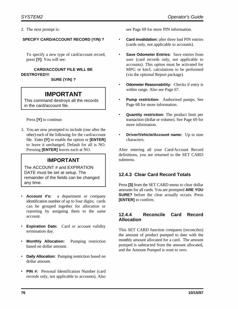
SYSTEM2 Operator's Guide
76 10/15/97
IMPORTANTThis command destroys all the recordsin the card/account file.
IMPORTANTThe ACCOUNT # and EXPIRATIONDATE must be set at setup. Theremainder of the fields can be changedany time.
2. The next prompt is: see Page 69 for more PIN information.
SPECIFY CARD/ACCOUNT RECORD (Y/N) ? • Card invalidation: after three bad PIN entries
To specify a new type of card/account record, • Save Odometer Entries: Save entries frompress [Y]. You will see: user (card records only, not applicable to
CARD/ACCOUNT FILE WILL BE MPG or km/L calculations to be performedDESTROYED!!! (via the optional Report package).
SURE (Y/N) ?
Press [Y] to continue. transaction (dollar or volume). See Page 69 for
3. You are now prompted to include (one after theother) each of the following for the card/account • Driver/Vehicle/Account name: Up to ninefile. Enter [Y] to enable the option or [ENTER] characters.to leave it unchanged. Default for all is NO.Pressing [ENTER] leaves each at NO. After entering all your Card/Account Record
• Account #'s: a department or companyidentification number of up to four digits; cardscan be grouped together for allocation orreporting by assigning them to the sameaccount.
• Expiration Date: Card or account validitytermination day.
• Monthly Allocation: Pumping restrictionbased on dollar amount.
• Daily Allocation: Pumping restriction based ondollar amount.
• PIN #: Personal Identification Number (cardrecords only, not applicable to accounts). Also
(cards only, not applicable to accounts).
accounts). This option must be activated for
• Odometer Reasonability: Checks if entry iswithin range. Also see Page 67.
• Pump restriction: Authorized pumps. SeePage 68 for more information.
• Quantity restriction: The product limit per
more information.
definitions, you are returned to the SET CARDsubmenu.
12.4.3 Clear Card Record Totals
Press [3] from the SET CARD menu to clear dollaramounts for all cards. You are prompted ARE YOUSURE? before the clear actually occurs. Press[ENTER] to confirm.
12.4.4 Reconcile Card RecordAllocation
This SET CARD function compares (reconciles)the amount of product pumped to date with themonthly amount allocated for a card. The amountpumped is subtracted from the amount allocated,and the Amount Pumped is reset to zero.
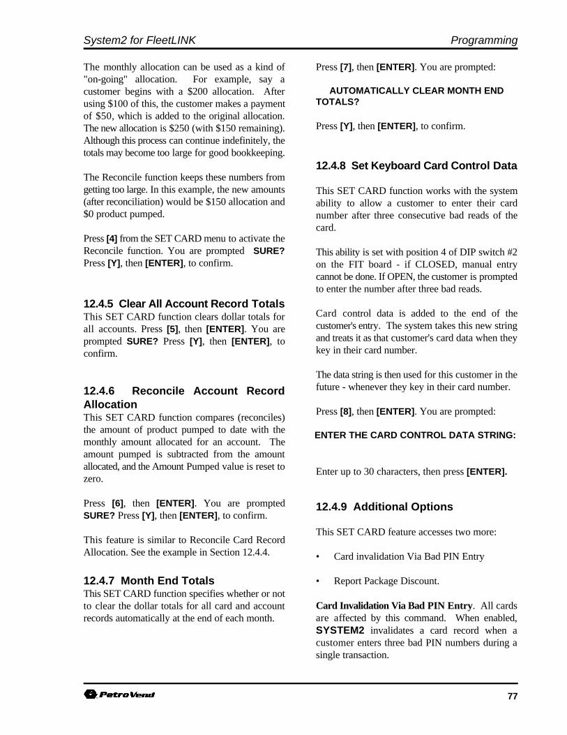
System2 for FleetLINK Programming
77
The monthly allocation can be used as a kind of Press [7], then [ENTER]. You are prompted:"on-going" allocation. For example, say acustomer begins with a $200 allocation. Afterusing $100 of this, the customer makes a paymentof $50, which is added to the original allocation.The new allocation is $250 (with $150 remaining).Although this process can continue indefinitely, thetotals may become too large for good bookkeeping.
The Reconcile function keeps these numbers fromgetting too large. In this example, the new amounts(after reconciliation) would be $150 allocation and$0 product pumped.
Press [4] from the SET CARD menu to activate theReconcile function. You are prompted SURE?Press [Y], then [ENTER], to confirm.
12.4.5 Clear All Account Record TotalsThis SET CARD function clears dollar totals forall accounts. Press [5], then [ENTER]. You areprompted SURE? Press [Y], then [ENTER], toconfirm.
12.4.6 Reconcile Account RecordAllocationThis SET CARD function compares (reconciles)the amount of product pumped to date with themonthly amount allocated for an account. Theamount pumped is subtracted from the amountallocated, and the Amount Pumped value is reset tozero.
Press [6], then [ENTER]. You are promptedSURE? Press [Y], then [ENTER], to confirm.
This feature is similar to Reconcile Card RecordAllocation. See the example in Section 12.4.4.
12.4.7 Month End TotalsThis SET CARD function specifies whether or notto clear the dollar totals for all card and accountrecords automatically at the end of each month.
AUTOMATICALLY CLEAR MONTH ENDTOTALS?
Press [Y], then [ENTER], to confirm.
12.4.8 Set Keyboard Card Control Data
This SET CARD function works with the systemability to allow a customer to enter their cardnumber after three consecutive bad reads of thecard.
This ability is set with position 4 of DIP switch #2on the FIT board - if CLOSED, manual entrycannot be done. If OPEN, the customer is promptedto enter the number after three bad reads.
Card control data is added to the end of thecustomer's entry. The system takes this new stringand treats it as that customer's card data when theykey in their card number.
The data string is then used for this customer in thefuture - whenever they key in their card number.
Press [8], then [ENTER]. You are prompted:
ENTER THE CARD CONTROL DATA STRING:
Enter up to 30 characters, then press [ENTER].
12.4.9 Additional Options
This SET CARD feature accesses two more:
• Card invalidation Via Bad PIN Entry
• Report Package Discount.
Card Invalidation Via Bad PIN Entry. All cardsare affected by this command. When enabled,SYSTEM2 invalidates a card record when acustomer enters three bad PIN numbers during asingle transaction.
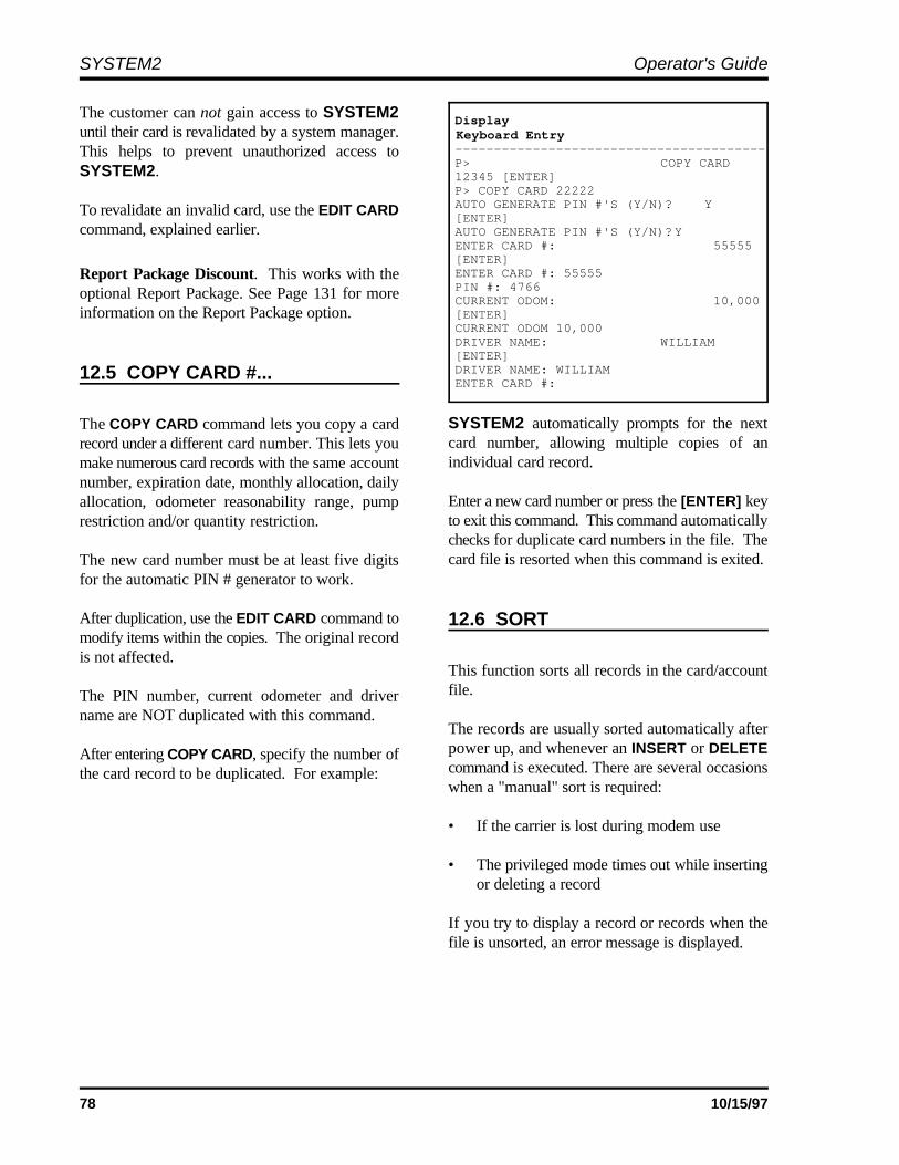
SYSTEM2 Operator's Guide
78 10/15/97
Display Keyboard Entry----------------------------------------P> COPY CARD12345 [ENTER]P> COPY CARD 22222AUTO GENERATE PIN #'S (Y/N)? Y[ENTER]AUTO GENERATE PIN #'S (Y/N)?YENTER CARD #: 55555[ENTER]ENTER CARD #: 55555PIN #: 4766CURRENT ODOM: 10,000[ENTER]CURRENT ODOM 10,000DRIVER NAME: WILLIAM[ENTER] DRIVER NAME: WILLIAM ENTER CARD #:
The customer can not gain access to SYSTEM2until their card is revalidated by a system manager.This helps to prevent unauthorized access toSYSTEM2.
To revalidate an invalid card, use the EDIT CARDcommand, explained earlier.
Report Package Discount. This works with theoptional Report Package. See Page 131 for moreinformation on the Report Package option.
12.5 COPY CARD #...
The COPY CARD command lets you copy a cardrecord under a different card number. This lets youmake numerous card records with the same accountnumber, expiration date, monthly allocation, dailyallocation, odometer reasonability range, pumprestriction and/or quantity restriction.
The new card number must be at least five digitsfor the automatic PIN # generator to work.
After duplication, use the EDIT CARD command tomodify items within the copies. The original recordis not affected.
The PIN number, current odometer and drivername are NOT duplicated with this command.
After entering COPY CARD, specify the number ofthe card record to be duplicated. For example:
SYSTEM2 automatically prompts for the nextcard number, allowing multiple copies of anindividual card record.
Enter a new card number or press the [ENTER] keyto exit this command. This command automaticallychecks for duplicate card numbers in the file. Thecard file is resorted when this command is exited.
12.6 SORT
This function sorts all records in the card/accountfile.
The records are usually sorted automatically afterpower up, and whenever an INSERT or DELETEcommand is executed. There are several occasionswhen a "manual" sort is required:
• If the carrier is lost during modem use
• The privileged mode times out while insertingor deleting a record
If you try to display a record or records when thefile is unsorted, an error message is displayed.

79
----------------TRANSACTION DATA-----------------------------------------------------------A: SHOW A: TRANS DATE TIME CARD ACCOUNTVEHICLEB: PRINT B: TRANS DATE TIME CARD ACCOUNT VEHICLESUMMARY
C: TRANS (#...)-----------------------------------------------------------C: SET D: TRANSD: CLEAR-----------------------------------------------------------E: CLEAR E: TRANS DATE #... SEQUENCE #...-----------------------------------------------------------F: REPORT-----------------------------------------------------------^ENTER COMMAND ^ENTER OPTION
13.0 Transaction Data Menu
From the MAIN menu, press [H]
13.1 SHOW/PRINT TRANS DATETIME CARD ACCOUNT VEHICLE
This function displays or prints completedtransactions stored in the SYSTEM2 data base.
Even though all transactions are recorded by thesystem, what you actually see is determined by theSET TRANS command, described below.
When you issue a SHOW TRANS or PRINTTRANS, you are prompted as follows:
ENTER DATE:ENTER TIME: time prompt.ENTER CARD:ENTER ACCOUNT:ENTER VEHICLE:
There are four possible types of responses to theseprompts. Pressing [ENTER] at each prompt tellsthe system to ignore that parameter.
To narrow the range of transactions to print orshow, enter a specific time, date, or number at aprompt. For example, to display only thetransactions from January 22, 1994, enter JAN 221994 at the date prompt, and then press [ENTER]at the other four prompts.
When specifying the time or date, you can alsoinclude one of two following prefixes:
< ("less than" sign). Will include alltransactions up to and including the currenttime or date. For example, to include alltransactions up to and including Jan 22, 1994,enter <JAN 22 1994 at the date prompt.
> ("greater than" sign). Will include alltransactions starting with and including thespecified time or date. For example, to includeall that occurred after 5:00 PM (and beforemidnight), you would enter >5:00 PM at the
An example of a typical transaction is shown on thenext page.
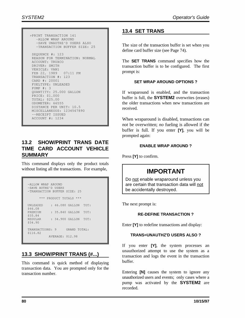
SYSTEM2 Operator's Guide
80 10/15/97
>PRINT TRANSACTION 161 -ALLOW WRAP AROUND -SAVE UNAUTHZ'D USERS ALSO -TRANSACTION BUFFER SIZE: 25
SEQUENCE #: 123 REASON FOR TERMINATION: NORMAL ACCOUNT: TRUXCO DRIVER: SMITH VEHICLE: VAN1 FEB 22, 1989 07:11 PM TRANSACTION #: 123 CARD #: 20001 FUELTYPE: UNLEADED PUMP #: 3 QUANTITY: 25.000 GALLON PRICE: $1.000 TOTAL: $25.00 ODOMETER: 66555 DISTANCE PER UNIT: 10.5 MISCELLANEOUS: 1234567890 --RECEIPT ISSUED ACCOUNT #: 1234
-ALLOW WRAP AROUND-SAVE AUTHZ'D USERS-TRANSACTION BUFFER SIZE: 25
*** PRODUCT TOTALS ***
UNLEADED : 46.080 GALLON TOT:$46.08PREMIUM : 35.840 GALLON TOT:$35.84REGULAR : 34.900 GALLON TOT:$34.90
TRANSACTIONS: 9 GRAND TOTAL:$116.82 AVERAGE: $12.98
IMPORTANTDo not enable wraparound unless youare certain that transaction data will notbe accidentally destroyed.
13.2 SHOW/PRINT TRANS DATETIME CARD ACCOUNT VEHICLESUMMARY
This command displays only the product totalswithout listing all the transactions. For example,
13.3 SHOW/PRINT TRANS (#...)
This command is quick method of displayingtransaction data. You are prompted only for thetransaction number.
13.4 SET TRANS
The size of the transaction buffer is set when youdefine card buffer size (see Page 74).
The SET TRANS command specifies how thetransaction buffer is to be configured. The firstprompt is:
SET WRAP AROUND OPTIONS ?
If wraparound is enabled, and the transactionbuffer is full, the SYSTEM2 overwrites (erases)the older transactions when new transactions arereceived.
When wraparound is disabled, transactions cannot be overwritten; no fueling is allowed if thebuffer is full. If you enter [Y], you will beprompted again:
ENABLE WRAP AROUND ?
Press [Y] to confirm.
The next prompt is:
RE-DEFINE TRANSACTION ?
Enter [Y] to redefine transactions and display:
TRANS=UNAUTHZ'D USERS ALSO ?
If you enter [Y], the system processes anunauthorized attempt to use the system as atransaction and logs the event in the transactionbuffer.
Entering [N] causes the system to ignore anyunauthorized users and events; only cases where apump was activated by the SYSTEM2 arerecorded.

System2 for FleetLINK Programming
81
The third SET TRANS prompt is:
SPECIFY DISPLAY FIELDS ?
This lets you tell the system which fields to displaywhen a SHOW TRANSACTION or PRINTTRANSACTION command is issued. Choose fromthe following fields:
ACCOUNT, DRIVER, VEHICLEDATE & TIMECARD #1CARD #2FUELTYPEPUMP #HOSE #QUANTITYPRICETOTALODOMETERDISTANCE PER UNITMISCELLANEOUSRECEIPT STATUSACCOUNT #
Chosen fields are also used in the ExternalComputer Transactions (see Page 111).
If access was denied to a fueler, only the first fourfields and the transaction number are recorded forthat transaction.
There must be at least one transaction recorded inyour system in order to show all the selected datafields.
The last SET TRANS option (displayed after theaccount number prompt) is:
COMPUTER FORMAT CHECK DATA IN HEADER ?
When transferring data to an external system in thecomputer format, an optional data check can beprefixed to the transaction header to provide greaterdata integrity. The data check includes: (1) thenumber of records and (2) the sum of the quantitiesfor records. See Page 111 for External Computerinstructions.
Press [Y] to enable or [N] to disable the data check.
13.5 CLEAR TRANS
The CLEAR TRANS command clears alltransactions. To ensure that you do not cleartransactions accidentally, the system prompts youa second time before clearing the transactions.
You cannot clear transactions in the middle of thebuffer.
13.6 CLEAR TRANSDATE #... SEQUENCE #...
This version of the CLEAR TRANS commandclears all transactions that occurred up to andincluding the specified transaction on the specifieddate.
13.7 REPORT
The REPORT command activates the optionalreport package. If the package is not installed inyour system, you will see:
** NOT AVAILABLE **
If you have the Report package, turn to Page 131for more information.

SYSTEM2 Operator's Guide
82 10/15/97
Notes:

83
----------------SYSTEM TOTALS------------------------------------------------------A: SHOW A: TRANS DATE TIME CARD ACCOUNTVEHICLEB: PRINT B: TRANS DATE TIME CARD ACCOUNT VEHICLESUMMARY
C: MIDNIGHTD: DAYE: SHIFT
------------------------------------------------------C: SHOW F: PUMP #... TOTALSD: PRINT G: PCT #... TOTALSE: CLEAR------------------------------------------------------F: SHOW H: FUELTYPE (#...) TOTALSG: PRINT------------------------------------------------------H: SHOW I: TANK (#...)I: PRINTJ: SET------------------------------------------------------^ENTER COMMAND ^ENTER OPTION
14.0 System Totals Menu
From the MAIN menu, press [I]
14.1 SHOW/PRINT TRANS DATE SUMMARYTIME CARD ACCOUNT VEHICLE
This version of SHOW TRANS or PRINT TRANSlets you print and show the completed transactionsthat stored in the SYSTEM2 data base.
This function is very similar to the SHOW/PRINTTRANS command explained in the TransactionData menu, Page 79.
14.2 SHOW/PRINT TRANS DATETIME CARD ACCOUNT VEHICLE
This command displays only product totals, withoutlisting all the transactions.
This function is very similar to the SHOW/PRINTTRANS SUMMARY command in the TransactionData menu, Page 80.
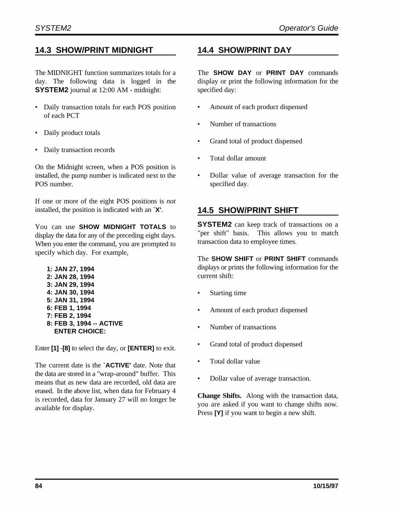
SYSTEM2 Operator's Guide
84 10/15/97
14.3 SHOW/PRINT MIDNIGHT 14.4 SHOW/PRINT DAY
The MIDNIGHT function summarizes totals for a The SHOW DAY or PRINT DAY commandsday. The following data is logged in the display or print the following information for theSYSTEM2 journal at 12:00 AM - midnight:
• Daily transaction totals for each POS positionof each PCT
• Daily product totals
• Daily transaction records
On the Midnight screen, when a POS position isinstalled, the pump number is indicated next to thePOS number.
If one or more of the eight POS positions is notinstalled, the position is indicated with an `X'.
You can use SHOW MIDNIGHT TOTALS todisplay the data for any of the preceding eight days.When you enter the command, you are prompted tospecify which day. For example,
1: JAN 27, 19942: JAN 28, 19943: JAN 29, 19944: JAN 30, 19945: JAN 31, 19946: FEB 1, 19947: FEB 2, 19948: FEB 3, 1994 -- ACTIVE ENTER CHOICE:
Enter [1] -[8] to select the day, or [ENTER] to exit.
The current date is the `ACTIVE' date. Note thatthe data are stored in a "wrap-around" buffer. Thismeans that as new data are recorded, old data areerased. In the above list, when data for February 4is recorded, data for January 27 will no longer beavailable for display.
specified day:
• Amount of each product dispensed
• Number of transactions
• Grand total of product dispensed
• Total dollar amount
• Dollar value of average transaction for thespecified day.
14.5 SHOW/PRINT SHIFT
SYSTEM2 can keep track of transactions on a"per shift" basis. This allows you to matchtransaction data to employee times.
The SHOW SHIFT or PRINT SHIFT commandsdisplays or prints the following information for thecurrent shift:
• Starting time
• Amount of each product dispensed
• Number of transactions
• Grand total of product dispensed
• Total dollar value
• Dollar value of average transaction.
Change Shifts. Along with the transaction data,you are asked if you want to change shifts now.Press [Y] if you want to begin a new shift.
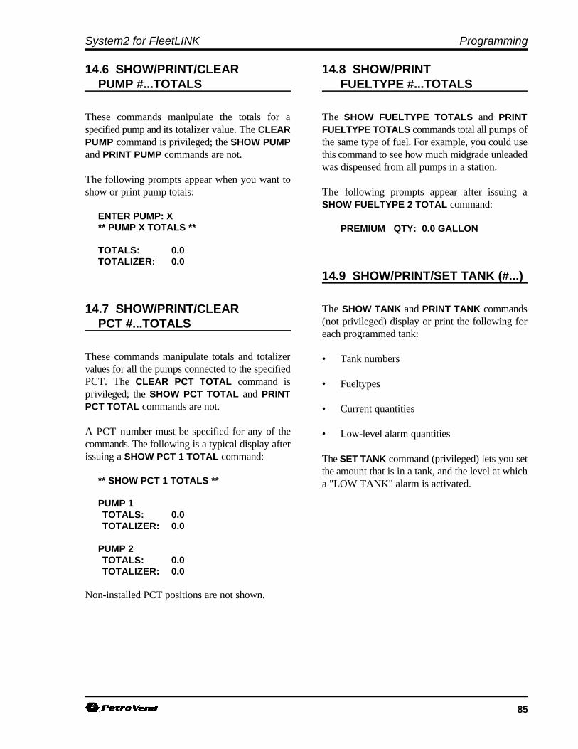
System2 for FleetLINK Programming
85
14.6 SHOW/PRINT/CLEAR 14.8 SHOW/PRINTPUMP #...TOTALS FUELTYPE #...TOTALS
These commands manipulate the totals for a The SHOW FUELTYPE TOTALS and PRINTspecified pump and its totalizer value. The CLEAR FUELTYPE TOTALS commands total all pumps ofPUMP command is privileged; the SHOW PUMP the same type of fuel. For example, you could useand PRINT PUMP commands are not. this command to see how much midgrade unleaded
The following prompts appear when you want toshow or print pump totals: The following prompts appear after issuing a
ENTER PUMP: X** PUMP X TOTALS **
TOTALS: 0.0TOTALIZER: 0.0
14.7 SHOW/PRINT/CLEARPCT #...TOTALS
These commands manipulate totals and totalizervalues for all the pumps connected to the specifiedPCT. The CLEAR PCT TOTAL command isprivileged; the SHOW PCT TOTAL and PRINTPCT TOTAL commands are not.
A PCT number must be specified for any of thecommands. The following is a typical display afterissuing a SHOW PCT 1 TOTAL command:
** SHOW PCT 1 TOTALS **
PUMP 1TOTALS: 0.0TOTALIZER: 0.0
PUMP 2TOTALS: 0.0TOTALIZER: 0.0
Non-installed PCT positions are not shown.
was dispensed from all pumps in a station.
SHOW FUELTYPE 2 TOTAL command:
PREMIUM QTY: 0.0 GALLON
14.9 SHOW/PRINT/SET TANK (#...)
The SHOW TANK and PRINT TANK commands(not privileged) display or print the following foreach programmed tank:
• Tank numbers
• Fueltypes
• Current quantities
• Low-level alarm quantities
The SET TANK command (privileged) lets you setthe amount that is in a tank, and the level at whicha "LOW TANK" alarm is activated.

SYSTEM2 Operator's Guide
86 10/15/97
Notes:

87
---------------JOURNAL PRINTER-------------------------------------------A: SHOW A: JOURNAL PRINTERB: PRINTC: SET-------------------------------------------C: LOCK B: PRINTERD: UNLOCK-------------------------------------------^ENTER COMMAND ^ENTER OPTION
15.0 Journal Printer Menu
From the MAIN menu, press [J]
15.1 SHOW/PRINT/SETJOURNAL PRINTER
An external printer can be connected to thePRINTER port on the back of the FSC to make ahard copy of all transaction data, providing addedprotection against data loss.
The journal printer records transaction, pump andproduct numbers, date and time, first card number,the product quantity and dollar total.
The SHOW JOURNAL and PRINT JOURNALcommands display current printer configuration. Use the privileged SET JOURNAL command tospecify the system will operate with an externalprinter. If so, you can also specify which of thefollowing items will be printed:
1. Account Name, Driver, Vehicle names.Odometer entry. Miscellaneous entry.
2. Account number and second card.
The following is a typical prompt sequence afterissuing a SET JOURNAL command and answering[Y] to all prompts:
OFFICE JOURNAL (Y/N) YSET JOURNAL PRINTER OPTIONS (Y/N) YPRINT:ACCOUNT, DRIVER, VEHICLE, ODOM, and MISC(Y/N)ACCOUNT #, CARD 2 (Y/N)JOURNAL ERROR OPTION (Y/N)
-- ENABLE AUTH ON JOURNAL ERROR (Y/N)
The JOURNAL ERROR OPTION specifies if thesystem should authorize fueling when the printer isnot operating.
The printer may "block" if an error, such as a paperoutage, occurs. After fixing the error, unblock thecommunication with the SET PRINTER command.
15.2 LOCK/UNLOCK PRINTER
The LOCK command lets you turn OFF the loggingfunction for the printer, useful for when multiplePRINT commands are executed.
If you want to print several items (for example,several types of transaction data) you can keep theprintouts together by issuing the LOCK PRINTERcommand. No "incoming" items will be printeduntil you turn OFF the LOCK.
The UNLOCK PRINTER command returns theprinter to its normal logging function. Anytransactions that were locked out are printed whenthe printer is unlocked.
If no command is generated for 10 minutes whilethe printer is locked, the system exits the privilegedmode and unlocks the printer.

SYSTEM2 Operator's Guide
88 10/15/97
Notes:
89
Appendix A - Setup Worksheet
SYSTEM TIMES (Page 29)
Forward: _________________ Backward: ______________System On: ________________ System Off: ______________Receipts Only: ________________ Time Adjust: ______________Light On: ________________ Light Off: ______________
SYSTEM DEVICES (Page 31)
FIT Setup
FIT #1 Issue receipts? yes noLimit for receiving a receipt (0..99) ______Enable keyboard access? yes noPCTs to shut off on E-stop 1, 2, 3, 4 Valid pump numbers __ __ __ __ __ __ __ __
FIT #2 Issue receipts? yes noLimit for receiving a receipt (0..99) ______Enable keyboard access yes noPCTs to shut off on E-stop 1, 2, 3, 4 Valid pump numbers: __ __ __ __ __ __ __ __
FIT #3 Issue receipts? yes noLimit for receiving a receipt (0..99) ______Enable keyboard access? yes noPCTs to shut off on E-stop 1, 2, 3, 4 Valid pump numbers: __ __ __ __ __ __ __ __
FIT #4 Issue receipts? yes noLimit for receiving a receipt (0..99) ______Enable keyboard access? yes noPCTs to shut off on E-stop 1, 2, 3, 4 Valid pump numbers: __ __ __ __ __ __ __ __
Installed FITs
FIT #1 FIT #2 FIT #3 FIT #4
SYSTEM2 Operator's Guide
90 10/15/97
OPT Setup
OPT #1 Issue receipts? yes noLimit for receiving a receipt (0..99) ______
Enable keyboard access? yes no
Valid pump numbers __ __ __ __ __ __ __ __
OPT #2 Issue receipts? yes no
Limit for receiving a receipt (0..99) ______
Enable keyboard access? yes noValid pump numbers __ __ __ __ __ __ __ __
OPT #3 Issue receipts? yes noLimit for receiving a receipt (0..99) ______
Enable keyboard access? yes no
Valid pump numbers __ __ __ __ __ __ __ __
OPT #4 Issue receipts? yes no
Limit for receiving a receipt (0..99) ______
Enable keyboard access? yes noValid pump numbers __ __ __ __ __ __ __ __
OPT #5 Issue receipts? yes noLimit for receiving a receipt (0..99) ______
Enable keyboard access? yes no
Valid pump numbers __ __ __ __ __ __ __ __
OPT #6 Issue receipts? yes no
Limit for receiving a receipt (0..99) ______
Enable keyboard access? yes noValid pump numbers __ __ __ __ __ __ __ __
OPT #7 Issue receipts? yes noLimit for receiving a receipt (0..99) ______
Enable keyboard access? yes no
Valid pump numbers __ __ __ __ __ __ __ __
OPT #8 Issue receipts? yes no
Limit for receiving a receipt (0..99) ______
Enable keyboard access? yes noValid pump numbers __ __ __ __ __ __ __ __
OPT #9 Issue receipts? yes noLimit for receiving a receipt (0..99) ______
Enable keyboard access? yes no
Valid pump numbers __ __ __ __ __ __ __ __
OPT #10 Issue receipts? yes no
Limit for receiving a receipt (0..99) ______
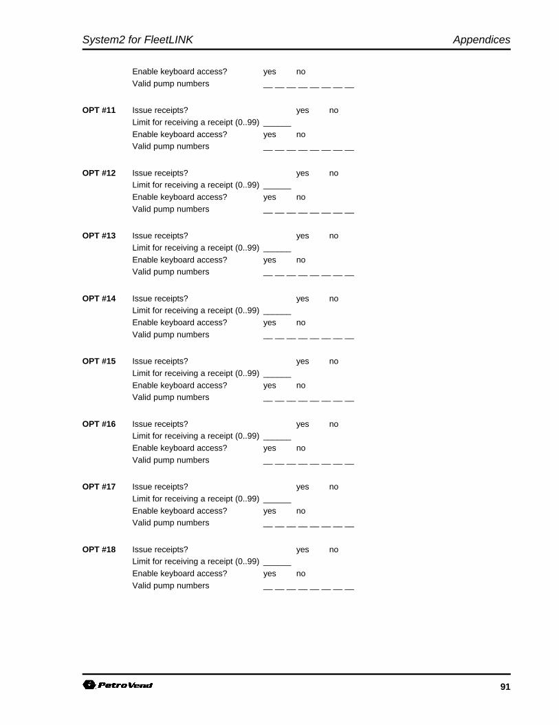
System2 for FleetLINK Appendices
91
Enable keyboard access? yes no
Valid pump numbers __ __ __ __ __ __ __ __
OPT #11 Issue receipts? yes no
Limit for receiving a receipt (0..99) ______
Enable keyboard access? yes noValid pump numbers __ __ __ __ __ __ __ __
OPT #12 Issue receipts? yes noLimit for receiving a receipt (0..99) ______
Enable keyboard access? yes no
Valid pump numbers __ __ __ __ __ __ __ __
OPT #13 Issue receipts? yes no
Limit for receiving a receipt (0..99) ______
Enable keyboard access? yes noValid pump numbers __ __ __ __ __ __ __ __
OPT #14 Issue receipts? yes noLimit for receiving a receipt (0..99) ______
Enable keyboard access? yes no
Valid pump numbers __ __ __ __ __ __ __ __
OPT #15 Issue receipts? yes no
Limit for receiving a receipt (0..99) ______
Enable keyboard access? yes noValid pump numbers __ __ __ __ __ __ __ __
OPT #16 Issue receipts? yes noLimit for receiving a receipt (0..99) ______
Enable keyboard access? yes no
Valid pump numbers __ __ __ __ __ __ __ __
OPT #17 Issue receipts? yes no
Limit for receiving a receipt (0..99) ______
Enable keyboard access? yes noValid pump numbers __ __ __ __ __ __ __ __
OPT #18 Issue receipts? yes noLimit for receiving a receipt (0..99) ______
Enable keyboard access? yes no
Valid pump numbers __ __ __ __ __ __ __ __
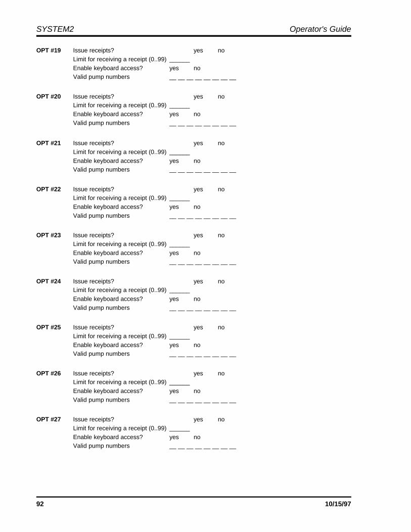
SYSTEM2 Operator's Guide
92 10/15/97
OPT #19 Issue receipts? yes no
Limit for receiving a receipt (0..99) ______
Enable keyboard access? yes noValid pump numbers __ __ __ __ __ __ __ __
OPT #20 Issue receipts? yes noLimit for receiving a receipt (0..99) ______
Enable keyboard access? yes no
Valid pump numbers __ __ __ __ __ __ __ __
OPT #21 Issue receipts? yes no
Limit for receiving a receipt (0..99) ______
Enable keyboard access? yes noValid pump numbers __ __ __ __ __ __ __ __
OPT #22 Issue receipts? yes noLimit for receiving a receipt (0..99) ______
Enable keyboard access? yes no
Valid pump numbers __ __ __ __ __ __ __ __
OPT #23 Issue receipts? yes no
Limit for receiving a receipt (0..99) ______
Enable keyboard access? yes noValid pump numbers __ __ __ __ __ __ __ __
OPT #24 Issue receipts? yes noLimit for receiving a receipt (0..99) ______
Enable keyboard access? yes no
Valid pump numbers __ __ __ __ __ __ __ __
OPT #25 Issue receipts? yes no
Limit for receiving a receipt (0..99) ______
Enable keyboard access? yes noValid pump numbers __ __ __ __ __ __ __ __
OPT #26 Issue receipts? yes noLimit for receiving a receipt (0..99) ______
Enable keyboard access? yes no
Valid pump numbers __ __ __ __ __ __ __ __
OPT #27 Issue receipts? yes no
Limit for receiving a receipt (0..99) ______
Enable keyboard access? yes noValid pump numbers __ __ __ __ __ __ __ __
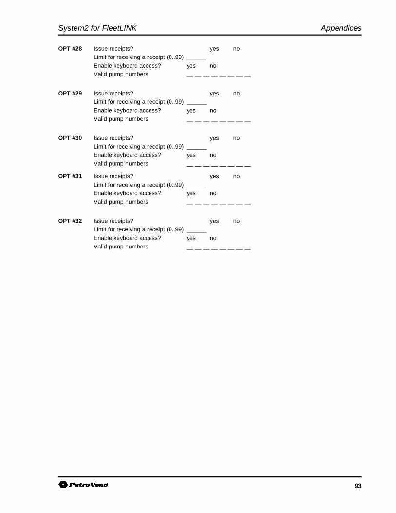
System2 for FleetLINK Appendices
93
OPT #28 Issue receipts? yes no
Limit for receiving a receipt (0..99) ______
Enable keyboard access? yes noValid pump numbers __ __ __ __ __ __ __ __
OPT #29 Issue receipts? yes noLimit for receiving a receipt (0..99) ______
Enable keyboard access? yes no
Valid pump numbers __ __ __ __ __ __ __ __
OPT #30 Issue receipts? yes no
Limit for receiving a receipt (0..99) ______
Enable keyboard access? yes noValid pump numbers __ __ __ __ __ __ __ __
OPT #31 Issue receipts? yes no
Limit for receiving a receipt (0..99) ______Enable keyboard access? yes no
Valid pump numbers __ __ __ __ __ __ __ __
OPT #32 Issue receipts? yes no
Limit for receiving a receipt (0..99) ______
Enable keyboard access? yes no
Valid pump numbers __ __ __ __ __ __ __ __
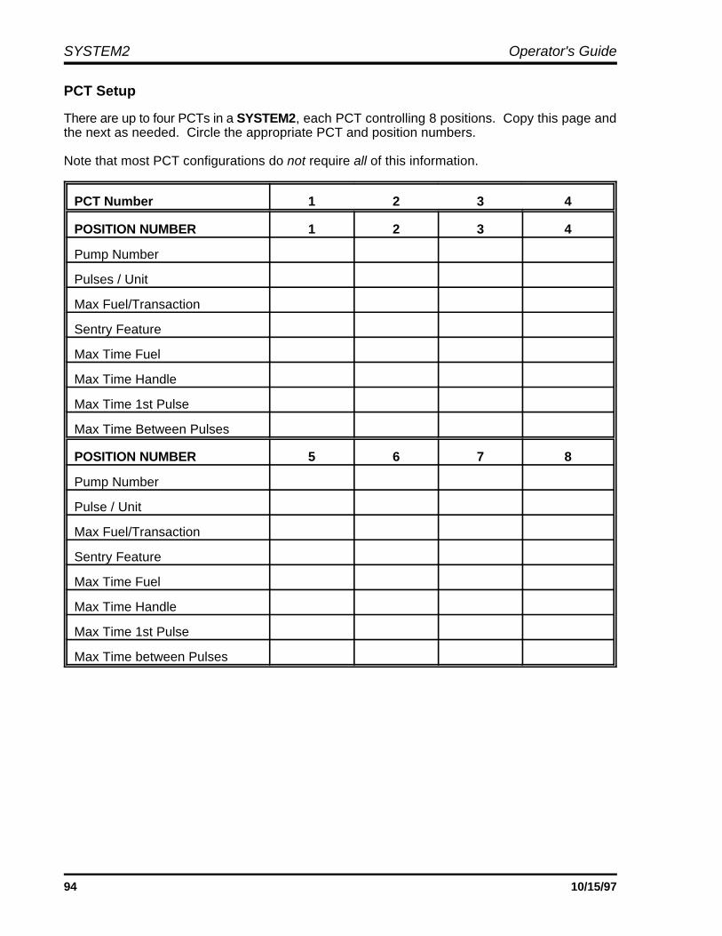
SYSTEM2 Operator's Guide
94 10/15/97
PCT Setup
There are up to four PCTs in a SYSTEM2, each PCT controlling 8 positions. Copy this page andthe next as needed. Circle the appropriate PCT and position numbers.
Note that most PCT configurations do not require all of this information.
PCT Number 1 2 3 4
POSITION NUMBER 1 2 3 4
Pump Number
Pulses / Unit
Max Fuel/Transaction
Sentry Feature
Max Time Fuel
Max Time Handle
Max Time 1st Pulse
Max Time Between Pulses
POSITION NUMBER 5 6 7 8
Pump Number
Pulse / Unit
Max Fuel/Transaction
Sentry Feature
Max Time Fuel
Max Time Handle
Max Time 1st Pulse
Max Time between Pulses
System2 for FleetLINK Appendices
95
PCT Number 1 2 3 4
POSITION NUMBER 1 / 5 2 / 6 3 / 7 4 / 8
Fueltype Code #
Fueling Tank
Clear Pump Totals
Totalizer Value
Installed PCT positions:
PCT #1 POSITION # 1 2 3 4 5 6 7 8
PCT #2 POSITION # 1 2 3 4 5 6 7 8
PCT #3 POSITION # 1 2 3 4 5 6 7 8
PCT #4 POSITION # 1 2 3 4 5 6 7 8
Instaledl PCTs:
PCT #1 PCT #2 PCT #3 PCT #4

SYSTEM2 Operator's Guide
96 10/15/97
CUSTOMER MESSAGES (Page 37)
Language OneMessage # Prompt
1 _______________________________________________________________________
2 _______________________________________________________________________
3 _______________________________________________________________________
4 _______________________________________________________________________
5 _______________________________________________________________________
6 _______________________________________________________________________
7 _______________________________________________________________________
8 _______________________________________________________________________
9 _______________________________________________________________________
10 _______________________________________________________________________
11 _______________________________________________________________________
12 _______________________________________________________________________
13 _______________________________________________________________________
14 _______________________________________________________________________
15 _______________________________________________________________________
16 _______________________________________________________________________
17 _______________________________________________________________________
18 _______________________________________________________________________
19 _______________________________________________________________________
20 _______________________________________________________________________
21 _______________________________________________________________________
22 _______________________________________________________________________
23 _______________________________________________________________________
24 _______________________________________________________________________
25 _______________________________________________________________________

System2 for FleetLINK Appendices
97
26 _______________________________________________________________________
27 _______________________________________________________________________
28 _______________________________________________________________________
29 _______________________________________________________________________
30 _______________________________________________________________________
31 _______________________________________________________________________
32 _______________________________________________________________________
33 _______________________________________________________________________
34 _______________________________________________________________________
35 _______________________________________________________________________
36 _______________________________________________________________________
37 _______________________________________________________________________
38 _______________________________________________________________________
39 _______________________________________________________________________
40 _______________________________________________________________________
41 _______________________________________________________________________
42 _______________________________________________________________________
43 _______________________________________________________________________
44 _______________________________________________________________________
45 _______________________________________________________________________
46 _______________________________________________________________________
47 _______________________________________________________________________
48 _______________________________________________________________________
49 _______________________________________________________________________
50 _______________________________________________________________________
51 _______________________________________________________________________
52 _______________________________________________________________________
SYSTEM2 Operator's Guide
98 10/15/97
Language TwoMessage # Prompt
1 _______________________________________________________________________
2 _______________________________________________________________________
3 _______________________________________________________________________
4 _______________________________________________________________________
5 _______________________________________________________________________
6 _______________________________________________________________________
7 _______________________________________________________________________
8 _______________________________________________________________________
9 _______________________________________________________________________
10 _______________________________________________________________________
11 _______________________________________________________________________
12 _______________________________________________________________________
13 _______________________________________________________________________
14 _______________________________________________________________________
15 _______________________________________________________________________
16 _______________________________________________________________________
17 _______________________________________________________________________
18 _______________________________________________________________________
19 _______________________________________________________________________
20 _______________________________________________________________________
21 _______________________________________________________________________
22 _______________________________________________________________________
23 _______________________________________________________________________
24 _______________________________________________________________________
25 _______________________________________________________________________

System2 for FleetLINK Appendices
99
26 _______________________________________________________________________
27 _______________________________________________________________________
28 _______________________________________________________________________
29 _______________________________________________________________________
30 _______________________________________________________________________
31 _______________________________________________________________________
32 _______________________________________________________________________
33 _______________________________________________________________________
34 _______________________________________________________________________
35 _______________________________________________________________________
36 _______________________________________________________________________
37 _______________________________________________________________________
38 _______________________________________________________________________
39 _______________________________________________________________________
40 _______________________________________________________________________
41 _______________________________________________________________________
42 _______________________________________________________________________
43 _______________________________________________________________________
44 _______________________________________________________________________
45 _______________________________________________________________________
46 _______________________________________________________________________
47 _______________________________________________________________________
48 _______________________________________________________________________
49 _______________________________________________________________________
50 _______________________________________________________________________
51 _______________________________________________________________________
52 _______________________________________________________________________

SYSTEM2 Operator's Guide
100 10/15/97
Keyboard Messages
Language One
Key Message Default Function
1 YES
2 NO
Language Two
Key Message Default Function
1 YES
2 NO
Receipt Header
Language ONE Entry Language TWO Entry Color
Line 1: RED BLACK
Line 2: RED BLACK
Line 3: RED BLACK
Line 4: RED BLACK
Receipt Trailer
Language ONE Entry Language TWO Entry Color
Line 1: RED BLACK
Line 2: RED BLACK
Line 3: RED BLACK
Line 4: RED BLACK
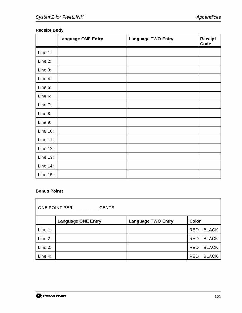
System2 for FleetLINK Appendices
101
Receipt Body
Language ONE Entry Language TWO Entry ReceiptCode
Line 1:
Line 2:
Line 3:
Line 4:
Line 5:
Line 6:
Line 7:
Line 8:
Line 9:
Line 10:
Line 11:
Line 12:
Line 13:
Line 14:
Line 15:
Bonus Points
ONE POINT PER __________ CENTS
Language ONE Entry Language TWO Entry Color
Line 1: RED BLACK
Line 2: RED BLACK
Line 3: RED BLACK
Line 4: RED BLACK
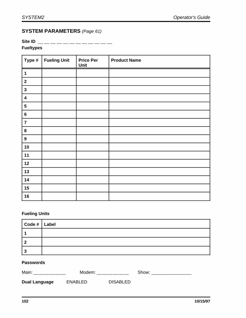
SYSTEM2 Operator's Guide
102 10/15/97
SYSTEM PARAMETERS (Page 61)
Site ID __ __ __ __ __ __ __ __ __ __ __ __ Fueltypes
Type # Fueling Unit Price Per Product NameUnit
1
2
3
4
5
6
7
8
9
10
11
12
13
14
15
16
Fueling Units
Code # Label
1
2
3
Passwords
Main: __ __ __ __ __ __ Modem: __ __ __ __ __ __ Show: ________________
Dual Language ENABLED DISABLED
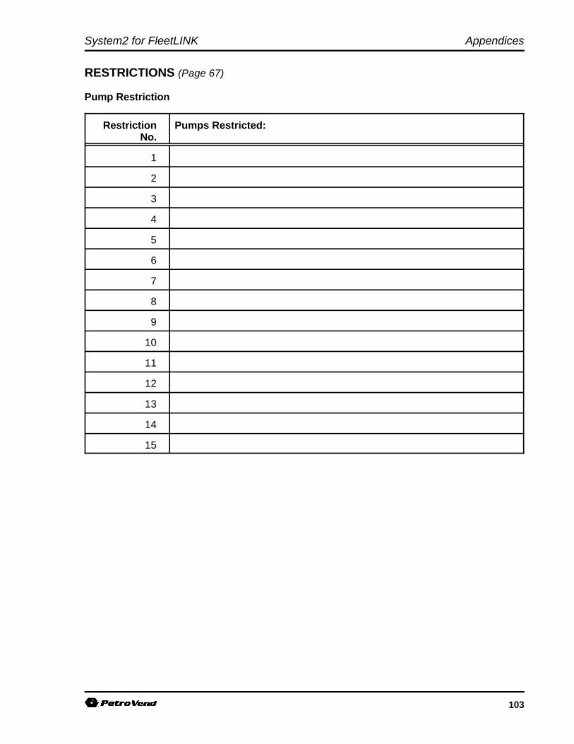
System2 for FleetLINK Appendices
103
RESTRICTIONS (Page 67)
Pump Restriction
Restriction Pumps Restricted:No.
1
2
3
4
5
6
7
8
9
10
11
12
13
14
15

SYSTEM2 Operator's Guide
104 10/15/97
Quantity Restriction
Code No. Max. Qty. Code No. Max. Qty
1 9
2 10
3 11
4 12
5 13
6 14
7 15
8
CARDS/ACCOUNTS (Page 71)
Account No: _________
Monthly Allocation: _________
Misc. Entry: ENABLED DISABLED
PIN Entry: ENABLED DISABLED
Odometer Entry: ENABLED DISABLED
Pump Restriction Code: _________
Driver Name: _______________________
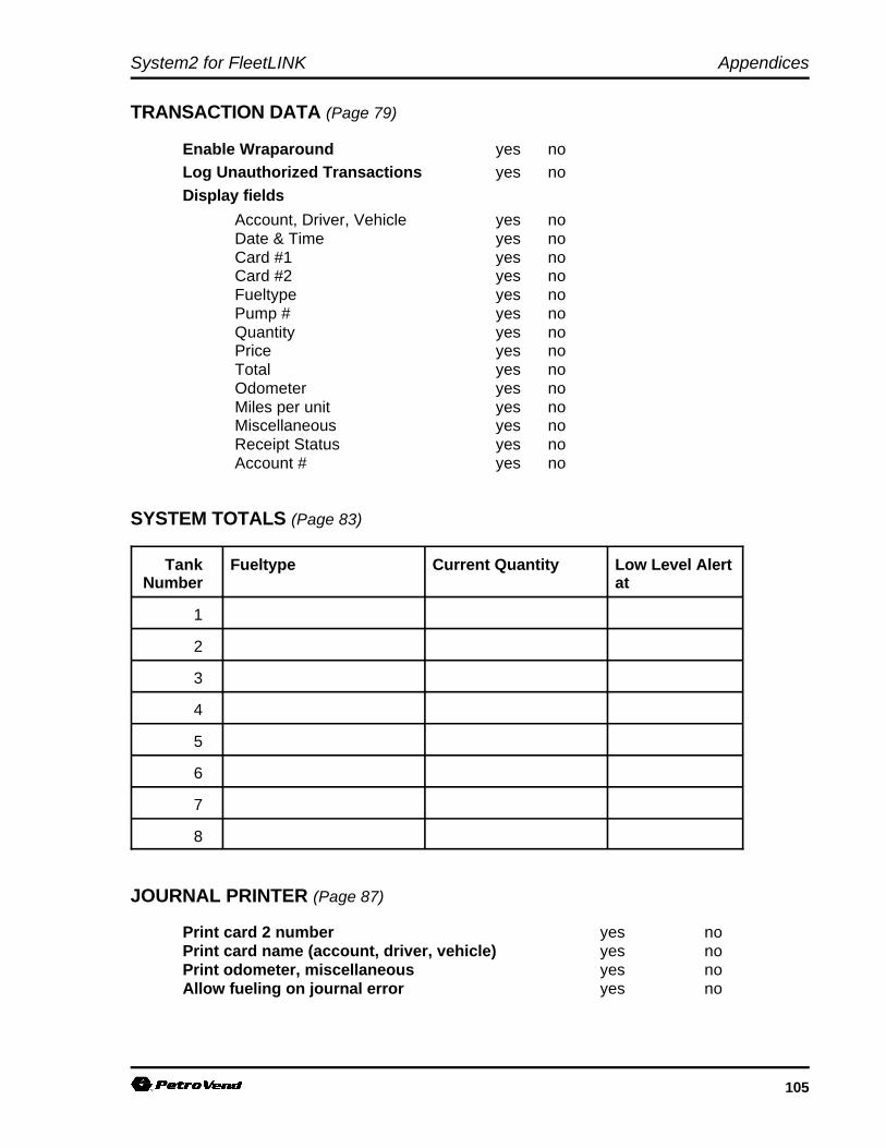
System2 for FleetLINK Appendices
105
TRANSACTION DATA (Page 79)
Enable Wraparound yes noLog Unauthorized Transactions yes no
Display fields
Account, Driver, Vehicle yes noDate & Time yes noCard #1 yes noCard #2 yes noFueltype yes noPump # yes noQuantity yes noPrice yes noTotal yes noOdometer yes noMiles per unit yes noMiscellaneous yes noReceipt Status yes noAccount # yes no
SYSTEM TOTALS (Page 83)
Tank Fueltype Current Quantity Low Level AlertNumber at
1
2
3
4
5
6
7
8
JOURNAL PRINTER (Page 87)
Print card 2 number yes noPrint card name (account, driver, vehicle) yes noPrint odometer, miscellaneous yes noAllow fueling on journal error yes no

SYSTEM2 Operator's Guide
106 10/15/97
Notes:

System2 for FleetLINK Appendices
107
Appendix B - Memory Levels & Allocations
The following table shows the maximum number of transactions and the maximum number of cards or keysavailable with the standard and optional (expanded) levels of RAM in your System2. "Minimum Options" and"Maximum Options" refers to the options you enable or disable in the SET CARD procedure. The memorylevel is displayed or set through the "RAM" option in the System Parameters menu on Page 61.
The Messaging feature is disabled for all memory numbers specified. The “Approx. Number Of Cards” isrounded to the nearest hundred.
MEMORY SIZE TRANSACTIONSSIZE/LEVEL CODE
TRANSACTION NUMBER OF CARDS/KEYS AVAILABLEAPPROX. NUMBER OF
With With MaximumMinimum Options
Options EnabledEnabled
Level 1 - Standard 4 100 10,400 3,600(256 Kb)
40 1,000 5,600 1,900
60 1,500 2,900 1,000
Level 2 - Optional 40 1,000 22,200 7,000(512 Kb)
80 2,000 14,900 5,100
120 3,000 9,500 3,300
Level 3 - Optional 40 1,000 49,300 17,000(1 Mb)
100 2,500 41,300 14,300
200 5,000 28,000 9,700
300 7,500 14,600 5,100
Level 4 (Option) 40 1,000 107,500 37,200(2 Mb)
200 5,000 86,200 29,800
400 10,000 59,500 20,600
600 15,000 32,900 11,400

SYSTEM2 Operator's Guide
108 10/15/97
Notes:
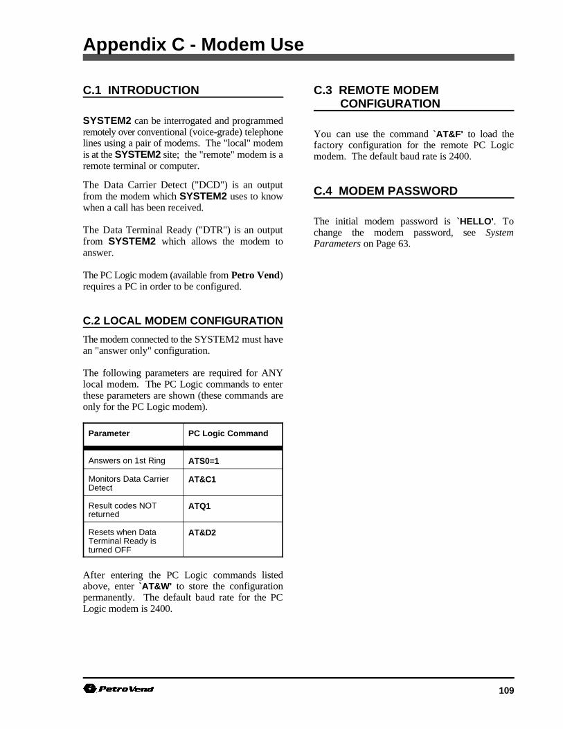
109
Appendix C - Modem Use
C.1 INTRODUCTION C.3 REMOTE MODEM
SYSTEM2 can be interrogated and programmedremotely over conventional (voice-grade) telephonelines using a pair of modems. The "local" modemis at the SYSTEM2 site; the "remote" modem is aremote terminal or computer.
The Data Carrier Detect ("DCD") is an outputfrom the modem which SYSTEM2 uses to knowwhen a call has been received.
The Data Terminal Ready ("DTR") is an outputfrom SYSTEM2 which allows the modem toanswer.
The PC Logic modem (available from Petro Vend)requires a PC in order to be configured.
C.2 LOCAL MODEM CONFIGURATION
The modem connected to the SYSTEM2 must havean "answer only" configuration.
The following parameters are required for ANYlocal modem. The PC Logic commands to enterthese parameters are shown (these commands areonly for the PC Logic modem).
Parameter PC Logic Command
Answers on 1st Ring ATS0=1
Monitors Data CarrierDetect
AT&C1
Result codes NOTreturned
ATQ1
Resets when DataTerminal Ready isturned OFF
AT&D2
After entering the PC Logic commands listedabove, enter `AT&W' to store the configurationpermanently. The default baud rate for the PCLogic modem is 2400.
CONFIGURATION
You can use the command `AT&F' to load thefactory configuration for the remote PC Logicmodem. The default baud rate is 2400.
C.4 MODEM PASSWORD
The initial modem password is `HELLO'. Tochange the modem password, see SystemParameters on Page 63.

SYSTEM2 Operator's Guide
110 10/15/97
Notes:
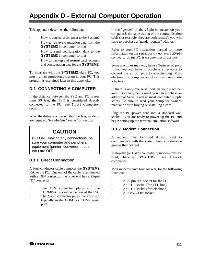
111
CAUTIONBEFORE making any connections, besure your computer and peripheralequipment (printer, converter, modem,etc.) are OFF.
Appendix D - External Computer Operation
This appendix describes the following:
• How to connect a computer to the System2 cable (for example, they are both female), you will• How to retrieve transaction data from the
SYSTEM2 in computer format• How to send configuration data to the
SYSTEM2 in computer format• How to backup and restore card, account
and configuration data for the SYSTEM2.
To interface with the SYSTEM2 via a PC, youmust run an emulation program in your PC. Thisprogram is explained later in this appendix.
D.1 CONNECTING A COMPUTER
If the distance between the FSC and PC is lessthan 50 feet, the FSC is considered directlyconnected to the PC. See Direct Connectionsection.
When the distance is greater than 50 feet, modemsare required. See Modem Connection section.
D.1.1 Direct Connection
A four-conductor cable connects the SYSTEM2FSC to the PC. One end of the cable is terminatedwith a DIN connector, the other end has a 25-pin"D" connector.
• The DIN connector plugs into theTERMINAL socket on the rear of the FSC
• The 25-pin connector plugs into your PC,typically in the COM1 or COM2 serialport.
If the "gender" of the 25-pin connector on yourcomputer is the same as that of the communication
have to purchase a "gender-bender" adaptor.
Refer to your PC instruction manual for moreinformation on the serial ports - not every 25-pinconnector on the PC is a communications port.
Some machines may only have a 9-pin serial port.If so, you will have to purchase an adaptor toconvert the 25 pin plug to a 9-pin plug. Mostelectronic or computer supply stores carry theseadapters.
If there is only one serial port on your machine,and it is already being used, you can purchase anadditional Serial Card at most computer supplystores. Be sure to read your computer owner'smanual prior to buying or installing a card.
Plug the PC power cord into a standard wallsocket. You are ready to power up the PC andbegin setting up the terminal emulation software.
D.1.2 Modem Connection
A modem must be used if you want tocommunicate with the system from any distancegreater than 50 feet.
A Hayes® (or Hayes compatible) modem must beused, because SYSTEM2 uses Hayes®commands.
Most modems have four sockets, for the followingfunctions:
• A 25-pin "D" socket for the PC• An RJ11 socket (for TEL line)• An RJ11 socket (for telephone)• A POWER IN socket

SYSTEM2 Operator's Guide
112 10/15/97
The modem should have come with the cables you If you are using direct connection, you will need toneed to make the following connections. (If not, set the software to "go local". If you are using ayou can purchase what you need at most computer modem, you will need to set its program switches.supply stores.)
1. Connect the 25-pin socket to the COM1 orCOM2 serial port on the back of yourcomputer.
2. Connect a phone cable from the modemRJ11 "LINE IN" jack to your facilitytelephone jack.
3. If you want the PC to share its line with atelephone, connect the telephone to theRJ11 modem "TEL" jack.
You cannot use the telephone (for voicecommunication) and the modemsimultaneously.
4. Plug the power adapter into its socket onthe modem and into a standard 115 VACwall socket.
D.2 TERMINALEMULATION SOFTWARE
For a PC to communicate with SYSTEM2, youmust run a terminal emulation program. PetroVend strongly suggests you use PROCOMM®emulation software, made by DATASTORMTECHNOLOGIES, INC. Contact your Petro Venddistributor for details.
Read the manual for your Terminal Emulationsoftware carefully. You will need to set thefollowing values (refer to the System2 InstallationManual for instructions on changing thesesettings):
Baud Rate . . . . . Must match SYSTEM2Data Bits . . . . . . 7COMM Port . . . . PC port being usedParity . . . . . . . . EvenStop Bits . . . . . . 1
You will also need to enter the telephone number ofthe SYSTEM2 site.
D.3 TRANSACTION DATA FORMAT
D.3.1 Description
The transaction data format is designed to be readby people, and includes a header with configurationdata and labels for each included field. In thedisplay format, the transmission of transactionrecords can be cued from the keyboard.
The header is described in a table on Page 114.
Computer formatted data eliminates these labels,substituting data checks, field codes and fieldseparators. This format is meant to transfertransaction data to a computer data base.
The Field Codes are described on Page 114, 115.
To pace the data stream, the transmission of eachtransaction record must be cued by a specificcomputer response.
To retrieve transaction data in the computerformat, append the prefix `SHOW' and the suffix`CF' to one of the following commands (anexample appears on the next page):
TRANSACTIONSTRANSACTION ###TRANSACTIONS WHERE DATE = mmm dd,yyyyTRANSACTIONS WHERE DATE < mmm dd,yyyyTRANSACTIONS WHERE DATE > mmm dd,yyyyTRANSACTIONS WHERE TIME = hh:mmam/pmTRANSACTIONS WHERE TIME < hh:mmam/pmTRANSACTIONS WHERE TIME > hh:mmam/pmTRANSACTIONS WHERE CARD = #TRANSACTIONS WHERE VEHICLE = #TRANSACTIONS WHERE ACCOUNT = #
System2 for FleetLINK Appendices
113
External Computer Output SYSTEM2 Response ---------------------------------------------------------------------SH TRANS 123CF|CR|LF| abcdefghijklmno/07|CR|LF|
123/I/TRUXCO---/SMITH----/VAN1-----/
02221989/0711/0123/20001--------------/
60001--------------/03/03/0025000/00100/
000002500/0066555/105/1234567890/1/1234/
11/|CR|LF||CR|LF| //|CR|LF|
The following command will call up transaction Each record is terminated with `|CR|LF|'. The123 in computer format: external computer responds with `|CR|LF|' to
SHOW TRANSACTIONS 123 CF
Search commands can be combined with `AND' inthe computer format. For example:
SH TRANS WH DAT = JAN 1,1989 AND WH TIM > 5:00 PM CF
Transaction report functions are explained in moredetail on Page 79.
When data is requested from SYSTEM2 in thecomputer format, SYSTEM2 first transmits thetransaction header and the first transaction. Thisheader always includes:
- Codes to indicate which transaction fields willbe included in the transmitted record(s)
- a 2-digit checksum and a carriage return
- a line feed (`|CR|LF|').
All transactions include the sequence number andReason For Termination code(s). The fields areincluded as specified by the transaction field codeslisted in the header. All items are separated by aslash (`/').
The Reason For Termination codes - both forGranted and Denied transactions - are listed in thetables on Page 116 and Page 117.
initiate the transmission of the next record.
The SYSTEM2 will send records each time itreceives `|CR|LF|' up to the last record. At the lastrecord, the system sends `//|CR|LF|'.
If the computer session is terminated by thecomputer with an `X', SYSTEM2 sends`\\|CR|LF|'.
If access was denied to a fueler, only the first fourdata fields are recorded (and can be transmitted)for that transaction.
The graphic below is an example of a transactiondata retrieval in the computer format. Note that adata check was not included in the header.
The `SHOW TRANSACTION' command has beenabbreviated to SH TRANS.
`|CR|LF|' indicates a carriage return and a linefeed.
`-' indicates a "space pad." A transactionrecord is sent as one string.
For clarity, the example shows line breaks betweenfields.

SYSTEM2 Operator's Guide
114 10/15/97
TRANSACTION HEADER
Item Format Pad Inclusion
Number of transactions 4 digits, left justified zero optional
Sum of quantities 9 digits, left justified zero optional
Transaction field codes 0 - 15 characters none always
Checksum 2 digits none always
TRANSACTION FIELD CODES
Code Field Format Pad
a Account/driver/vehicle 9 characters each space
b Date/time 8/4 digits: mmddyyyy/hhmm zero
c Transaction number 4 digits zero
d Card #1 19 digits, left justified space
e Card #2 19 digits, left justified space
f Fueltype 2 digits: 1 - 16 zero
g Pump number 2 digits: 1 - 99 or zero3 digits if hose number is specified
h Quantity 7 digits: ####.###, implied decimal zero
i Price 5 digits: ##.###, implied decimal zero
j Total 9 digits: #######.##, implied decimal zero
k Odometer 1 char, 6 digits: X######; `?' in 1st location zeroindicates unreasonable entry, `0' indicatesreasonable entry; all blanks if odometerentry not prompted (not valid for ChipKeys).
l MPG 3 spaces: mpg not available zero
m Miscellaneous 10 digits space
n Receipt status 1 digit: 1=issued; 0=not issued none
o Account number 4 spaces; account # not available zero
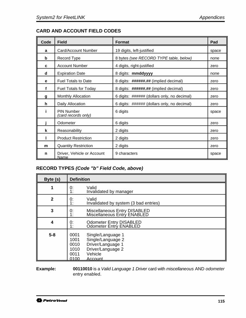
System2 for FleetLINK Appendices
115
CARD AND ACCOUNT FIELD CODES
Code Field Format Pad
a Card/Account Number 19 digits, left-justified space
b Record Type 8 bytes (see RECORD TYPE table, below) none
c Account Number 4 digits, right-justified zero
d Expiration Date 8 digits: mmddyyyy none
e Fuel Totals to Date 8 digits: ######.## (implied decimal) zero
f Fuel Totals for Today 8 digits: ######.## (implied decimal) zero
g Monthly Allocation 6 digits: ###### (dollars only, no decimal) zero
h Daily Allocation 6 digits: ###### (dollars only, no decimal) zero
i PIN Number 6 digits space(card records only)
j Odometer 6 digits zero
k Reasonability 2 digits zero
l Product Restriction 2 digits zero
m Quantity Restriction 2 digits zero
n Driver, Vehicle or Account 9 characters spaceName
RECORD TYPES (Code "b" Field Code, above)
Byte (s) Definition
1 0: Valid1: Invalidated by manager
2 0: Valid1: Invalidated by system (3 bad entries)
3 0: Miscellaneous Entry DISABLED1: Miscellaneous Entry ENABLED
4 0: Odometer Entry DISABLED1: Odometer Entry ENABLED
5-8 0001 Single/Language 11001 Single/Language 20010 Driver/Language 11010 Driver/Language 20011 Vehicle0100 Account
Example: 00110010 is a Valid Language 1 Driver card with miscellaneous AND odometerentry enabled.
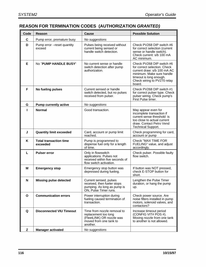
SYSTEM2 Operator's Guide
116 10/15/97
REASON FOR TERMINATION CODES (AUTHORIZATION GRANTED)
Code Reason Cause Possible Solution
C Pump error, premature busy No suggestions
D Pump error --reset quantity Pulses being received without Check PV268 DIP switch #6exceed current being sensed or for correct selection (current
handle switch detection. sense or handle switch).Check current: s/b 100 mAAC minimum.
E No `PUMP HANDLE BUSY' No current sense or handle Check PV268 DIP switch #6switch detection after pump for correct selection. Checkauthorization. current draw: s/b 100 mA AC
minimum. Make sure handletimeout is long enough.Check wiring to PV270 relayboard.
F No fueling pulses Current sensed or handle Check PV268 DIP switch #1switch detected, but no pulses for correct pulser type. Checkreceived from pulser. pulser wiring. Check pump's
First Pulse timer.
G Pump currently active No suggestions
I Normal Good transaction. May appear even forincomplete transaction ifcurrent sense threshold istoo close to actual currentdraw. Contact Petro VendTechnical Support.
J Quantity limit exceeded Card, account or pump limit Check programming for card,reached. account or pump
K Total transaction timeexceeded
Pump is programmed to Check "MAX TIME FORdispense fuel only for a length FUELING" value, and adjustof time. accordingly.
L Pulser error Only in flowswitch Check pulser. Possible faultyapplications. Pulses not flow switch.received within five seconds offlow switch activation.
M Emergency stop Emergency stop button was If button was NOT pressed,depressed during fueling. check E-STOP button for
short.
N Missing pulse detected Current sensed, pulses Lengthen the Pulse Timerreceived, then fueler stops duration, or hang the pumppumping. As long as pump is up.ON, Pulse Timer runs.
O Communication errors Power interruption during Check power source. Arefueling caused termination of noise filters installed in pumptransaction. motors, solenoid valves, and
contactors?
Q Disconnected VIU Timeout Time from nozzle removal to Increase timeout periodreplacement too long (CONFIG VIT# POS #).(FleetLINK) OR nozzle was Moving nozzle from one tankmoved from one tank to to another is not allowed.another.
Z Manager activated No suggestions

System2 for FleetLINK Appendices
117
REASON FOR TERMINATION CODES (AUTHORIZATION DENIED)
Code Reason Cause Possible Solution
b Bad PIN entry Wrong PIN entered three Verify PIN assigned to cardtimes. is correct. If yes, check the
keypad with FIT testprogram.
c Bad odometer entry Fueler's card is set for Re-enter odometer value.odometer reasonability, and Change reasonability (seeentry falls outside Section 11).acceptable limits.
d Bad miscellaneous entry NOT USED NOT USED
e User entry timeout Fueler did not enter data Operator error, or possibleafter inserting card. keypad malfunction.
f Card # not in positive file Invalid card.
g Card expired Card has expiration date Assign new expiration dateassigned to it. This date has to card, or issue new card.passed.
h Card record expired Card record in the system is Assign new expiration dateassigned an expiration date, to card record, or issue newwhich has passed. card.
i Card invalidated Card has not been validated Change validation status offor use in this system. card.
j Three bad PIN entries Fueler has entered incorrect Verify PIN assigned to cardPIN three times. is correct. If yes, check the
keypad with FIT testprogram.
k No allocation Daily or monthly limit has If daily, fueler must wait untilbeen reached on card or midnight to reset daily totals.account. If monthly, new limits must
be programmed or totalscleared.
n Account expired The card is assigned to an Program new expiration dateaccount that has expired. on account.
o Account invalidated Card has not been validated Change validation status forfor use in this system. the account.
p Account numbers do notmatch
Driver card is not assigned Program both cards to theto the same account as the same account.Vehicle card.
q Account record notfound
Card is assigned to an Program the card into theaccount record that has not file.been programmed into thecard/account file.
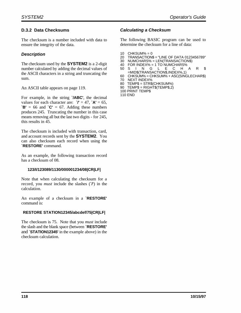
SYSTEM2 Operator's Guide
118 10/15/97
D.3.2 Data Checksums
The checksum is a number included with data toensure the integrity of the data.
Description
The checksum used by the SYSTEM2 is a 2-digitnumber calculated by adding the decimal values ofthe ASCII characters in a string and truncating thesum.
An ASCII table appears on page 119. For example, in the string `/ABC', the decimalvalues for each character are: `/' = 47, `A' = 65,`B' = 66 and `C' = 67. Adding these numbersproduces 245. Truncating the number in this casemeans removing all but the last two digits - for 245,this results in 45.
The checksum is included with transaction, card,and account records sent by the SYSTEM2. Youcan also checksum each record when using the`RESTORE' command.
As an example, the following transaction recordhas a checksum of 08.
123/I/123089/1130/000001234/08|CR|LF|
Note that when calculating the checksum for arecord, you must include the slashes (`/') in thecalculation.
An example of a checksum in a `RESTORE'command is:
RESTORE STATION12345/abcdef/75|CR|LF|
The checksum is 75. Note that you must includethe slash and the blank space (between `RESTORE'and `STATION12345' in the example above) in thechecksum calculation.
Calculating a Checksum
The following BASIC program can be used todetermine the checksum for a line of data:
10 CHKSUM% = 020 TRANSACTION$ = "LINE OF DATA 0123456789"30 NUMCHARS% = LEN(TRANSACTION$)40 FOR INDEX% = 1 TO NUMCHARS%50 S I N G L E C H A R $
=MID$(TRANSACTION$,INDEX%,1)60 CHKSUM% = CHKSUM% + ASC(SINGLECHAR$)70 NEXT INDEX%80 TEMP$ = STR$(CHKSUM%)90 TEMP$ = RIGHT$(TEMP$,2)100 PRINT TEMP$110 END
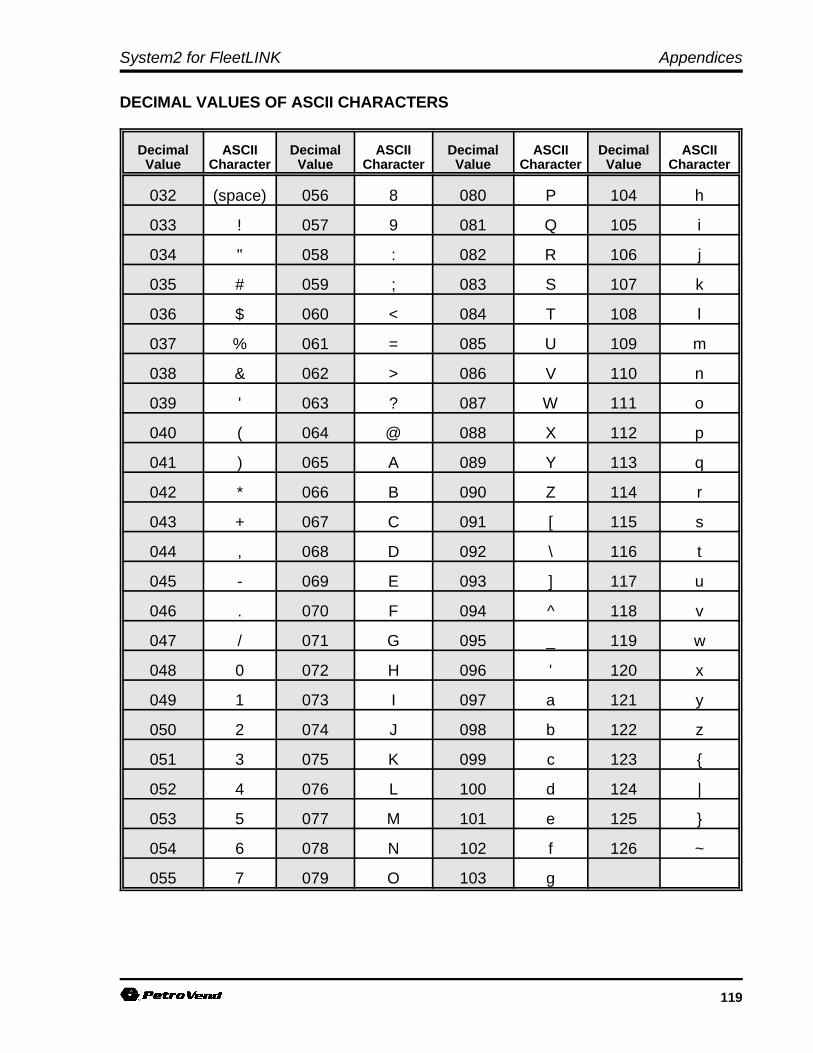
System2 for FleetLINK Appendices
119
DECIMAL VALUES OF ASCII CHARACTERS
Decimal ASCII Decimal ASCII Decimal ASCII Decimal ASCIIValue Character Value Character Value Character Value Character
032 (space) 056 8 080 P 104 h
033 ! 057 9 081 Q 105 i
034 " 058 : 082 R 106 j
035 # 059 ; 083 S 107 k
036 $ 060 < 084 T 108 l
037 % 061 = 085 U 109 m
038 & 062 > 086 V 110 n
039 ' 063 ? 087 W 111 o
040 ( 064 @ 088 X 112 p
041 ) 065 A 089 Y 113 q
042 * 066 B 090 Z 114 r
043 + 067 C 091 [ 115 s
044 , 068 D 092 \ 116 t
045 - 069 E 093 ] 117 u
046 . 070 F 094 ^ 118 v
047 / 071 G 095 _ 119 w
048 0 072 H 096 ' 120 x
049 1 073 I 097 a 121 y
050 2 074 J 098 b 122 z
051 3 075 K 099 c 123 {
052 4 076 L 100 d 124 |
053 5 077 M 101 e 125 }
054 6 078 N 102 f 126 ~
055 7 079 O 103 g

SYSTEM2 Operator's Guide
120 10/15/97
Computer Output SYSTEM2Response--------------------------------------------|CR|LF| P>BACKUP|CR|LF| STATION12345/abcdefghijklmn/44|CR|LF||CR|LF|1000400000000000000/00100001/1234/
02021990/00000809/001000/000100/--5903/0014060/02/00/01/RIKARD---/54|CR|LF|
|CR|LF| //|CR|LF|
D.3.3 Suppressing SYSTEM2 Prompts
The prefix COMPUTER can be placed before anycommand (except PRINT or SHOW) to suppressthe usual SYSTEM2 prompts and allow only acarriage return (`|CR|') or line feed (`|LF|') to bereturned.
The `P>' prompt is returned after each commandsequence has been successfully completed.Thefollowing command ssuppresses prompts, andenables checksum (the ".." enables checksum):
COMPUTER HELLO/HELLO/ ..
If the prompt is not returned when expected, a'R' (for RETRY) is returned instead.
To abort a command sequence, send a `^C' (ASCII03). Then, re-issue the command.
D.3.4 BACKUP & RESTORECommands
Backing up the card validation data allows you tosafeguard this information and to minimize systemdowntime when modifying or repairing aSYSTEM2. You can also backup one andrestore the data to another SYSTEM2 systemsare to have the same data base.
The `BACKUP' and `RESTORE' commands mustbe included as part of a computer program that canformat, store and transmit the raw computer dataproduced by the SYSTEM2.
The Phoenix or Phoenix Plus softwarepackage from Petro Vend, Inc. provides all theknow-how you need to backup and restore carddata quickly and easily using an IBM®-compatiblepersonal computer. Phoenix is available fromyour local Petro Vend distributor.
BACKUP/BACKUP Card Commands
These privileged commands transmit card andaccount data from the SYSTEM2 data bbbase toan external computer.
From an external computer, the BACKUPcommands request SYSTEM2 to transmit site id,
card and account field code(s), checksum, carriagereturn and a line feed (`|CR|LF|'), all separated bya slash (`/').
The records themselves are then sent following each`|CR|LF|' sent by the external computer. After thelast record, the SYSTEM2 sends `//|CR|LF|'.Checksum is explained on Page 118. The card andaccount field codes are listed in tables on Page 114,115.
• If NO card number is specified, backup startstransmission at the first card/account record
• If a card number is specified, the transmissionstarts at the specified record. Because therecords are sorted by number, this commandallows you to backup a latter portion of thefile.
Card and account records are sorted only bynumber; that is, account 2222 would be betweencard 1111 and card 3333. The BACKUPcommands back up both record types.
There is no command to specify only card or onlyaccount. The illustration on Page 86 illustrates atypical `BACKUP' communication sequence.
The following is an example of the informationexchanged with the `BACKUP' command.
In this example, `STATION12345' is the site IDand `44' is the checksum. The `-' indicates a "spacepad." Card and account records are sent as singlestrings. For clarity, the example above shows linebreaks between fields.
System2 for FleetLINK Appendices
121
IMPORTANTField codes must be specified with lowercase letters. The command RESTOREand any letters in the site ID must bespecified with upper case letters.
Computer Output SYSTEM2 Response----------------------------------------------|CR|LF|
P>RESTORE STATION12345/abcdefghijklmn/44|CR|LF|
|CR|LF|1000400000000000000/00100001/1234/02021990/00000809/001000/000100/--5903/0014060/02/00/01/RIKARD---/54|CR|LF|
|CR|LF|//|CR|LF|
P>
RESTORE site id (/fields) (/checksum)
This privileged command loads card and accountinformation from an external computer to theSYSTEM2 data base.
The SITE ID, CARD or ACCOUNT numbers(field "a") and RECORD TYPES (field "b") mustbe specified.
You may specify any additional field codes youwish to restore (see Restoring Fields below). Youmay also include a checksum for the command lineand/or the data records.
The field codes are listed on Page 114, 115.Checksum is explained on Page 118.
A typical `RESTORE' communication sequenceappears on Page 87. The following informationexchanged with the `RESTORE' command.
The `|CR|LF|' indicates a carriage return and a linefeed. The `-' indicates a "space pad." A card oraccount record must be sent as one string. For clarity,the example above shows line breaks between fields.
Restoring Fields
The SYSTEM2 allocates space in its data basewhen it receives the field codes.
You can restore a different number of fields thanwere in the data base when it was backed up.
For example, if a field was accidentally omittedduring configuration, you can add that field withoutlosing any card or account data.
First, back up the current card or account data.Then, use the SET CARD BUFFER command toinclude all the old and new fields.
This destroys the old data!
Finally, restore the card or account data, specifyingthe original fields plus the new field(s). The newfields can be filled with blanks or actual data.
Similarly, you can restore fewer fields - thisincreases the number of transactions or card andaccount records to be retained by the SYSTEM2.
Backing up the SYSTEM2 is like taking a snapshotof the data base. When data is restored, SYSTEM2returns to exactly the same state as when backedup.
Frequent data base backups reduce the need toupdate any specific fields (e.g. mileage) in the database when you use the RESTORE command.
UPDATE site id (/fields) (/checksum)
This privileged command modifies existing card oraccount records in the SYSTEM2.
SITE ID and CARD # must be specified for thiscommand; all other field changes are optional. Afield must be present in the original record to beupdated. Checksum data can be sent if desired.

SYSTEM2 Operator's Guide
122 10/15/97
Computer Output SYSTEM2 Response------------------------------------------------------UPDATE STATION12345/ai/80|CR|LF|
|CR|LF|1000400000000000000/--6666/91|CR|LF|
|CR|LF|//|CR|LF|
P>
IMPORTANTThe message `SYSTEM DOWN' is shownon the FIT display while backing up orrestoring configuration data. Normalfueling access is not allowed while thismessage is displayed.
The sequence for the UPDATE command is similar SYSRESTORE requires the FSC version numberto that of RESTORE (see Page 87). The following and checksum be specified. Version number mustis an example of changing the PIN number (field be the same for both the system that was backed up"i") for card 1000400000000000000 with the and the system that will be restored (the letter aftercommand. the version number can be ignored for this
The `|CR|LF|' indicates a carriage return and a linefeed. The `-' indicates a "space pad." A card oraccount record must be sent as one string.
SYSBACKUP Command
When this command is executed, SYSTEM2transmits the configuration data and the versionnumber of the system.
You CANNOT back up configuration data while atransaction in is progress.
SYSRESTORE ####(#)/<checksum>Command
When this command is invoked, SYSTEM2 doesthe following:
• tests the FSC version for compatibility• clears the card buffer• clears all transactions• restores configuration data• restarts all tasks• optionally changes the size of the system
memory (RAM)
command).
The FSC version number is printed on the cover ofthis manual; it can also be displayed using theSHOW SYSTEM command (Page 61).
The decimal point is not included.
For example, if a SYSTEM2 with FSC softwareversion 21.01E and standard RAM memory isbacked up, the command SYSRESTORE 2101 canbe used to reconfigure the same system or anothersystem with the same FSC version number and thesame size memory.
Differing RAM Size
SYSRESTORE also lets you restore differing sizesystem memory (RAM) by specifying the size code(#) for the system to be restored. RAM size code isexplained on Page 64.
The memory size specified with theSYSRESTORE command MUST match the actualmemory size of the SYSTEM2 being restored!
If the specified memory is larger than the system'smemory, SYSTEM2 locks up and must be coldstarted (the power and battery turned OFF and thenON). If the specified memory is smaller than thesystem's memory, SYSTEM2 will not be able toaccess the additional memory.
The SYSBACKUP command takes a "snapshot" ofSYSTEM2 data. Any configuration data that mayhave been changed since the last backup - time,date, tank levels, etc. - must be re-entered afterexecuting the SYSRESTORE command.
No pumps can be active at the time of aSYSBACKUP or SYSRESTORE command.

123
Appendix E - Troubleshooting
E.1 COMMON PROBLEMS AND POSSIBLE SOLUTIONS
Problem Possible Solution
No FIT display messages • Adjust "display viewing angle" potentiometer (on topof the display PC board).
`FAULTY PUMP' messageat FIT • Three "zero-quantity" transactions: re-install pump
with `INSTALL PCT # POSITION #' command
• Bad pump pulser: replace pulser
`RESET QUANTITY EXCEEDED'message at FIT
• Current sensor/pump handle selector switch inwrong position: change Switch #1 on PV-268 board
`SYSTEM DOWN'message at FIT
• FIT not installed: install FIT
• Petro-Net wiring problem: check, repair wiring
• Possible FIT board malfunction: run COMM test tocheck board; replace board if necessary
`SYSTEM DOWN'at all FITs • Possible FIT board malfunction(s): run COMM test
for each FIT board; replace board(s) if necessary
• Possible FSC board malfunction; if all FIT boardpass COMM test, replace FSC board
`INCORRECT CARD' messageat FIT • Incorrect network number encoded on card(s);
replace card(s)
• Incorrect network number programmed in FITEPROM: replace EPROM
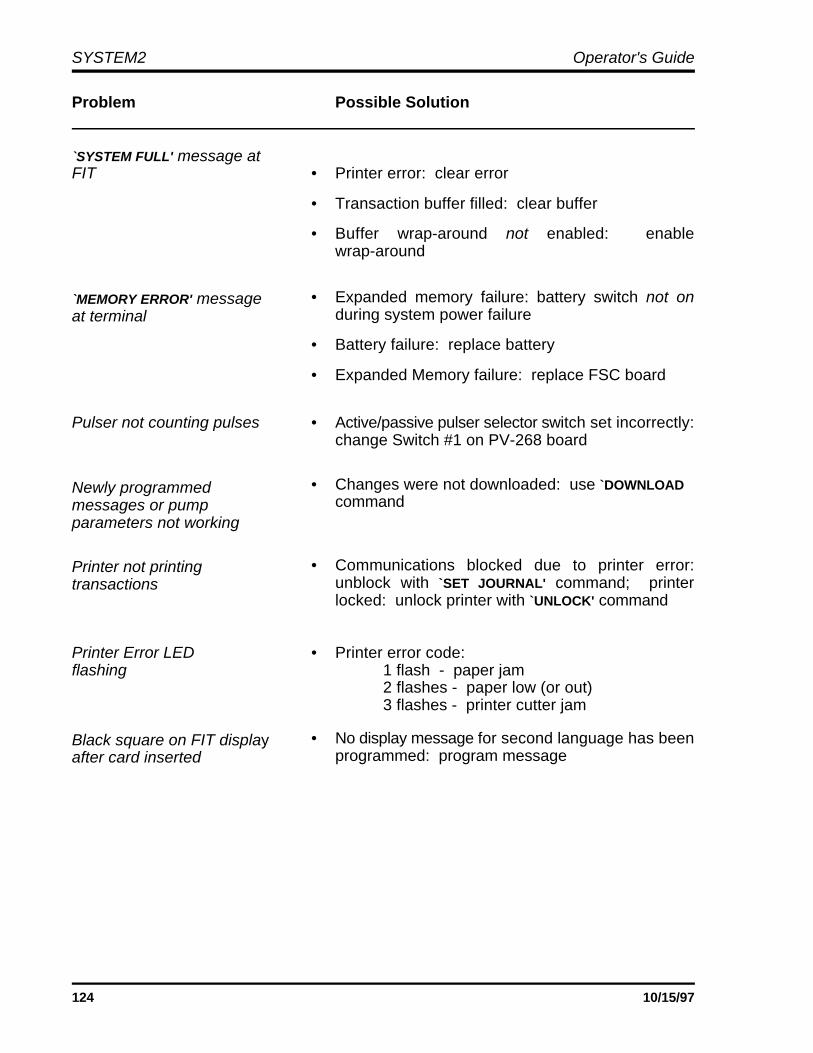
SYSTEM2 Operator's Guide
124 10/15/97
Problem Possible Solution
`SYSTEM FULL' message atFIT • Printer error: clear error
• Transaction buffer filled: clear buffer
• Buffer wrap-around not enabled: enablewrap-around
`MEMORY ERROR' messageat terminal
• Expanded memory failure: battery switch not onduring system power failure
• Battery failure: replace battery
• Expanded Memory failure: replace FSC board
Pulser not counting pulses • Active/passive pulser selector switch set incorrectly:change Switch #1 on PV-268 board
Newly programmedmessages or pump parameters not working
• Changes were not downloaded: use `DOWNLOAD command
Printer not printingtransactions
• Communications blocked due to printer error:unblock with `SET JOURNAL' command; printerlocked: unlock printer with `UNLOCK' command
Printer Error LED • Printer error code:flashing 1 flash - paper jam
2 flashes - paper low (or out) 3 flashes - printer cutter jam
Black square on FIT displayafter card inserted
• No display message for second language has beenprogrammed: program message
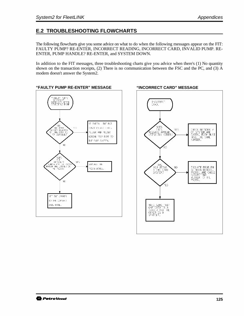
System2 for FleetLINK Appendices
125
“FAULTY PUMP RE-ENTER” MESSAGE “INCORRECT CARD” MESSAGE
E.2 TROUBLESHOOTING FLOWCHARTS
The following flowcharts give you some advice on what to do when the following messages appear on the FIT:FAULTY PUMP? RE-ENTER, INCORRECT READING, INCORRECT CARD, INVALID PUMP. RE-ENTER, PUMP HANDLE? RE-ENTER, and SYSTEM DOWN.
In addition to the FIT messages, three troubleshooting charts give you advice when there's (1) No quantityshown on the transaction receipts, (2) There is no communication between the FSC and the PC, and (3) Amodem doesn't answer the System2.
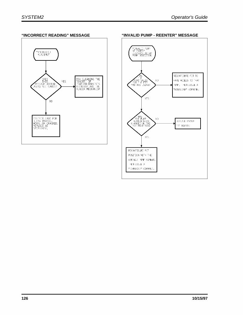
SYSTEM2 Operator's Guide
126 10/15/97
“INCORRECT READING” MESSAGE “INVALID PUMP - REENTER” MESSAGE

System2 for FleetLINK Appendices
127
“PUMP HANDLE - REENTER” MESSAGE “SYSTEM DOWN” MESSAGE
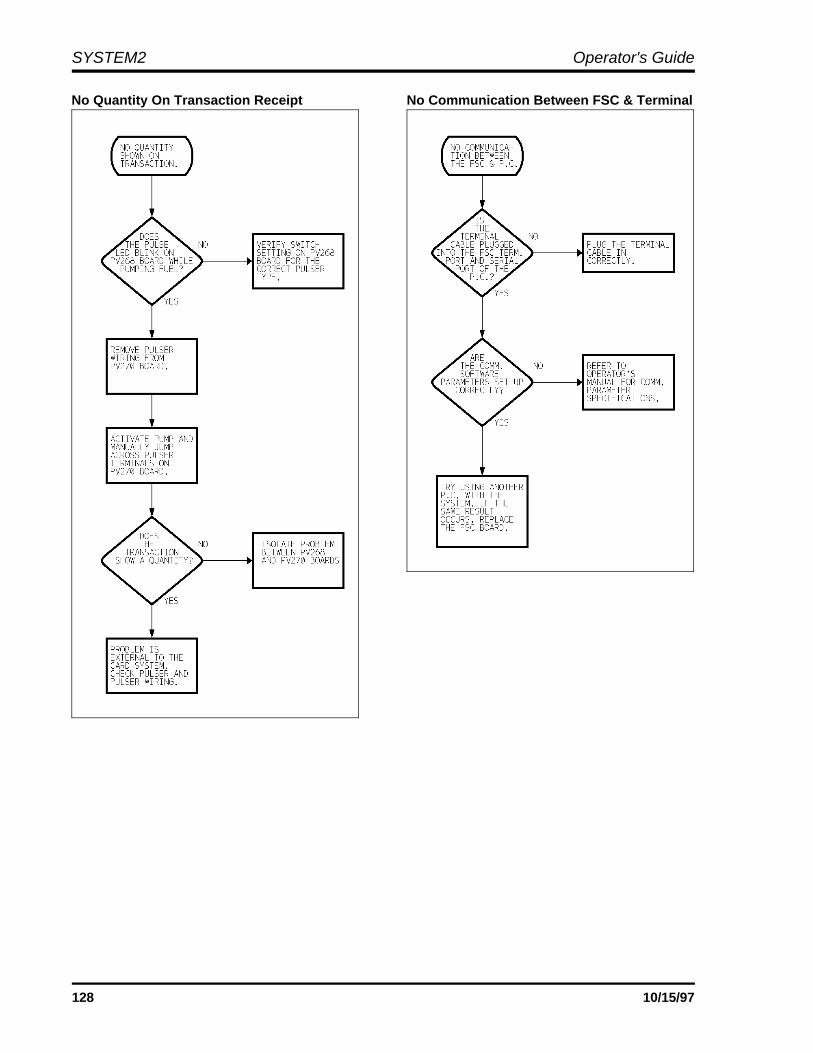
SYSTEM2 Operator's Guide
128 10/15/97
No Quantity On Transaction Receipt No Communication Between FSC & Terminal
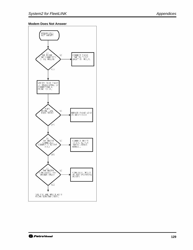
System2 for FleetLINK Appendices
129
Modem Does Not Answer

SYSTEM2 Operator's Guide
130 10/15/97
Notes:

131
OPTIONS:
QUICK
1. Run report based on custom defaults
RUN TIME ONLY
2. Specify card type, card range, account grouping andaccount range.3. Specify card type, card range, account grouping,account range, billing window and subtotals only.4. Specify card type, card range, account grouping,account range, billing window, subtotals only. custom heading, keyboard field label and fuel unittype.
PERMANENT
5. Enter custom defaults for all the parameters above
Enter option number or [RETURN] to exit.
Appendix F - Optional Report Package
F.1 DESCRIPTION
The optional Report Package allows you togenerate reports quickly and easily in a variety offormats.
All reports contain the following information foreach transaction:
Date and time of transactionTransaction numberMiscellaneous entryOdometer readingMileage per gallon (liters/100km)Pump numberproduct nameQuantity dispensedProduct price
Each report also contains the following datasummaries (or "subtotals"):
Total miles Average MPG (liter/100km)Cost per mile (or kilometer)Average price per gallon (or liter)Total quantity of fuel dispensedTotal price of fuel dispensed
Transactions may also be grouped by account
number. Reports can be displayed on the terminalor printer.
F.2 MODES OF OPERATION
Three modes of operation are available. The`QUICK' mode generates a report according to aformat that you have previously selected. Thisenables the fast generation of a "standard" report.
The `PERMANENT' mode is used to select theformat for the `QUICK' mode report.
The `RUN TIME ONLY' mode allows you to selecta "temporary" format and to generate one report inthis format. This mode enables you to createreports without affecting the `QUICK' mode format.

SYSTEM2 Operator's Guide
132 10/15/97
F.3 REPORT PARAMETERS
The following parameters (or "variables") can bespecified for the reports:
F.3.1 Card Type
There are three types of cards: single, driver andvehicle; only one type of card may be selected foreach report.
F.3.2 Card Range
An upper and lower card number may be entered tonarrow the transaction search to a limited range ofcards; press the [ENTER] key at both prompts tospecify all cards.
F.3.3 Account GroupingAn upper and lower account number may beentered to narrow the transaction search to a limitedrange of accounts; press the [ENTER] key at bothprompts to specify all accounts. Note that whenthe account option is selected, the transactions arearranged first by account number and then by cardnumber.
F.3.4 Billing WindowA starting and ending date may be entered tonarrow the transaction search to a limited range ofdates. This range is also called a "billing window."
F.3.5 Subtotals OnlyThis option prevents transaction data from beingincluded in a report; final totals and card subtotalsare always included.
F.3.6 Custom HeadingThe heading is printed at the top of the first page ofa report; up to three lines of up to 80 characterseach can be specified.F.3.7 Keyboard Field LabelThe customer may be prompted to enter a numberat the FIT as part of his transaction. These entriesappear under the `KEYBOARD FIELD' label in thereports. This label can be given any name up toeight characters in length.
F.3.8 Fueling Unit TypeLiters or gallons can be selected. Mileageefficiency is calculated as liters per 100 kilometersor miles per gallon, respectively.
F.4 RUNNING THE REPORT
To generate a report, you must be in the privilegedmode. At the privileged prompt, enter thecommand `REPORT'. The menu above isdisplayed.
F.4.1 Run-Time Only Mode
Enter the number for one of the `RUN TIME ONLY'options listed above (2, 3 or 4). The system thenprompts for the associated parameters. Theseparameters specify search type.
F.4.2 Quick/Permanent ModeTo generate a report in the `QUICK' mode, youmust first enter the `PERMANENT' mode and selectthe following parameters:
- Cardtype (single, driver or vehicle)- Card range (lower and upper limits)- Account grouping (lower and upper limits)- Subtotals only (data summaries)- Custom heading (3 lines of 80
characters)- Fueling unit type (liters or gallons)
Press the [ENTER] key without entering any data tobypass (and deactivate) a parameter. Note thatcard type and fueling unit can not be bypassed.
After specifying the parameters, the `QUICK' modecan be selected anytime to generate the "QuickReport." The system prompts for a billing windowand for an output device (terminal or printer) beforegenerating the report. The terminal is the defaultoutput device and may be entered simply bypressing the [ENTER] key.
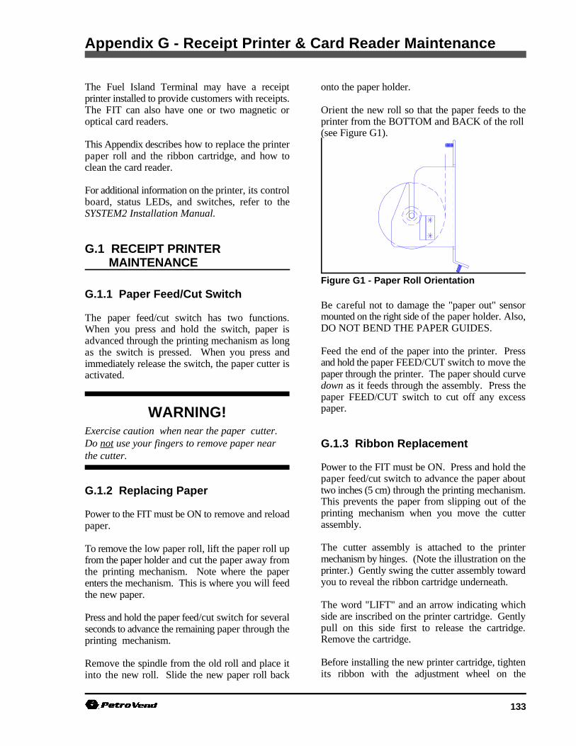
133
WARNING!Exercise caution when near the paper cutter. Do not use your fingers to remove paper nearthe cutter.
Figure G1 - Paper Roll Orientation
Appendix G - Receipt Printer & Card Reader Maintenance
The Fuel Island Terminal may have a receipt onto the paper holder.printer installed to provide customers with receipts.The FIT can also have one or two magnetic or Orient the new roll so that the paper feeds to theoptical card readers. printer from the BOTTOM and BACK of the roll
This Appendix describes how to replace the printerpaper roll and the ribbon cartridge, and how toclean the card reader.
For additional information on the printer, its controlboard, status LEDs, and switches, refer to theSYSTEM2 Installation Manual.
G.1 RECEIPT PRINTER MAINTENANCE
G.1.1 Paper Feed/Cut Switch
The paper feed/cut switch has two functions.When you press and hold the switch, paper isadvanced through the printing mechanism as longas the switch is pressed. When you press andimmediately release the switch, the paper cutter isactivated.
G.1.2 Replacing Paper
Power to the FIT must be ON to remove and reloadpaper.
To remove the low paper roll, lift the paper roll upfrom the paper holder and cut the paper away fromthe printing mechanism. Note where the paperenters the mechanism. This is where you will feedthe new paper.
Press and hold the paper feed/cut switch for severalseconds to advance the remaining paper through theprinting mechanism.
Remove the spindle from the old roll and place itinto the new roll. Slide the new paper roll back
(see Figure G1).
Be careful not to damage the "paper out" sensormounted on the right side of the paper holder. Also,DO NOT BEND THE PAPER GUIDES.
Feed the end of the paper into the printer. Pressand hold the paper FEED/CUT switch to move thepaper through the printer. The paper should curvedown as it feeds through the assembly. Press thepaper FEED/CUT switch to cut off any excesspaper.
G.1.3 Ribbon Replacement
Power to the FIT must be ON. Press and hold thepaper feed/cut switch to advance the paper abouttwo inches (5 cm) through the printing mechanism.This prevents the paper from slipping out of theprinting mechanism when you move the cutterassembly.
The cutter assembly is attached to the printermechanism by hinges. (Note the illustration on theprinter.) Gently swing the cutter assembly towardyou to reveal the ribbon cartridge underneath.
The word "LIFT" and an arrow indicating whichside are inscribed on the printer cartridge. Gentlypull on this side first to release the cartridge.Remove the cartridge.
Before installing the new printer cartridge, tightenits ribbon with the adjustment wheel on the

SYSTEM2 Operator's Guide
134 10/15/97
cartridge. The ribbon should be as tight as possible 1. System power should be ON.in order to fit into the narrow slot of the printer.
Gently snap the new ribbon cartridge into place. card, and immediately insert the card into theBe sure that the ribbon is properly positioned in its reader.slot. If the ribbon is noticeably visible after you install 3. Withdraw the card, and throw it away. Cardsthe cartridge, remove the cartridge and tighten the are single-use ONLY.ribbon.
Swing the cutter mechanism back into place.
G.1.4 Testing the Printer
To test the printer:
1. Press both the paper feed/cut switch and theprinter reset switch simultaneously.
2. Release the reset switch and hold the paperfeed/cut switch until the printing begins.
When the printer is properly installed andfunctioning, it prints a message with: (1)current printer software version, (2) samples ofall font sizes in both red and black print,(3) format selections for DIP switch position #1,and (4) selected currency symbol.
When the test is completed, the receipt is cut.
The printer RESET switch resets the printer. If theprinter jams (indicated by CR2 flashing), press theprinter reset button after correcting the cause of thejam (clearing an obstacle from the mechanism,freeing the paper or ribbon, etc.).
G.2 CARD READER CLEANING
ALL systems using optical or magnetic cardreaders require these readers be cleaned on aregular basis.
The reader should be cleaned at a minimum once amonth, though once a week cleaning is stronglysuggested. Clean the head more often for busy sites,or whenever performance begins to suffer(numerous bad reads, etc.).
You will need a Cleaning card (several suppliedwith the system), and isopropyl alcohol
2. Apply a little isopropyl alcohol to a cleaning

135
Appendix H - FleetLINK FSC Command Descriptions
This appendix contains new or modified FSC commands to control the FleetLINK system.
SHOW SYSTEM command
Shows if FleetLINK is ENABLED or DISABLED. If enabled, supported fleet numbers are listed (up to 32numbers can be factory-programmed). If disabled (no fleet numbers programmed), FleetLINK DISABLEDis displayed.
This command also shows installed VIT (Vehicle Information Terminal) and VIT position status for two VITswith up to 16 positions each. Similar to INSTALLED PCTs command.
Sample Command Execution
P> sh system e
SYSTEM 2: CARD RECORD VERSION #: 21.02A EPROM CHK: 61E5 FC3D -BAD CHECKSUM, CLEAR ERROR (Y/N)? y DISPLAY: 2x16 PPU: PROGRAMMABLE
FleetLINK ENABLED for Fleet/Station Numbers: 3333 5678 JAN 01,1995 06:38 PM SYSTEM ON BATTERY OK
INSTALLED FITs:INSTALLED OPTs:INSTALLED VITs:
VIT 1, POSITIONS: 1, 2, 3, 4, 5, 6, 7, 8, 9, 10, 11, 12, 13, 14, 15, 16 STATUS --running
INSTALLED PCTs: (std) PCT 1, POSITIONS: 1, 2 STATUS --running
LOW TANKS: NONEPOWER FAIL TIMES:
JAN 01,1995 12:00 AM JAN 03,1995 01:14 AM JAN 05,1995 01:54 AM JAN 07,1995 06:23 PM

SYSTEM2 Operator's Guide
136 10/15/97
INSTALL & REMOVE commands
These commands are similar to the INSTALL/REMOVE PCT # POSITION # commands.
Sample Command Execution
You Enter . . . . . System ResponseP> remove vit 1 . . OKAYP> install vit 1 . . . OKAYP> remove vit 1 pos 2 VIT 1 POSITION 2 OKAYP> install vit 1 pos 2 VIT 1 POSITION 2 OKAYP>
CONFIGURE VIT # POSITION # Command
See the SHOW VIT # POSITION # command below for description of fields
You Enter . . . . . System Response
P> config vit 1 pos 16 VIT VERSION: 20260304
VIT 1 POSITION 16 CONFIGURATION |- Activate PCT 2 Position 8
|- Authorize with Pump Handle: OFF|- Maximum Disconnect Time (seconds)
|- Status Noise Threshold: 1
ENTER NEW PCT: 3
ENTER NEW POSITION: 8
AUTHORIZE WITH HANDLE ON (Y/N)?
NENTER MAXIMUM DISCONNECT TIME (SECONDS)
5ENTER STATUS NOISE THRESHOLD:
1P>

System2 for FleetLINK Appendices
137
SHOW VIT # POSITION # Command
Explanation of Fields
Configuration Fields
|- Activate PCT # Position #One VIT position is assigned to one hose.
Default: VIT 1 POS 1-8: PCT 1 POS 1-8VIT 1 POS 9-16 PCT 2 POS 1-8VIT 2 POS 1-8 PCT 3 POS 1-8VIT 2 POS 9-16 PCT 4 POS 1-8
|- Authorize with Pump Handle: OFF/ONApplies only with PCT positions set up for pump handle
OFF - Requires the pump handle switch be turned off before the transaction can begin. ON - Ignores the pump handle and forces the pump on.
|- Enter Maximum Disconnect Time (seconds): 5
Maximum allowed time that the pump remains ON after the connection between the vehicle’s transmittercoil and the nozzle’s receiver coil is broken. When this time expires, the pump shuts off (default is 5seconds).
|- Status Noise Threshold: 1-127Tolerance of the system to ignore connection breaks caused by noise at the receiver coil. Should not bechanged unless directed to by Petro Vend personnel (default is 1).
Data Fields These fields are self-explanatory:
|- Channel State: "NO CONNECTION ESTABLISHED""CONNECTION ESTABLISHED"
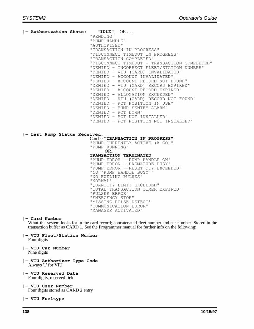
SYSTEM2 Operator's Guide
138 10/15/97
|- Authorization State: "IDLE", OR..."PENDING""PUMP HANDLE""AUTHORIZED""TRANSACTION IN PROGRESS""DISCONNECT TIMEOUT IN PROGRESS”"TRANSACTION COMPLETED"“DISCONNECT TIMEOUT - TRANSACTION COMPLETED”"DENIED - INCORRECT FLEET/STATION NUMBER""DENIED - VIU (CARD) INVALIDATED""DENIED - ACCOUNT INVALIDATED""DENIED - ACCOUNT RECORD NOT FOUND""DENIED - VIU (CARD) RECORD EXPIRED""DENIED - ACCOUNT RECORD EXPIRED""DENIED - ALLOCATION EXCEEDED""DENIED - VIU (CARD) RECORD NOT FOUND""DENIED - PCT POSITION IN USE""DENIED - PUMP SENTRY ALARM""DENIED - PCT DOWN""DENIED - PCT NOT INSTALLED""DENIED - PCT POSITION NOT INSTALLED"
|- Last Pump Status Received: Can be “TRANSACTION IN PROGRESS”
"PUMP CURRENTLY ACTIVE (A GO)" "PUMP RUNNING"
OR... TRANSACTION TERMINATED "PUMP ERROR --PUMP HANDLE ON" "PUMP ERROR --PREMATURE BUSY" "PUMP ERROR --RESET QTY EXCEEDED" "NO 'PUMP HANDLE BUSY'" "NO FUELING PULSES" "NORMAL" "QUANTITY LIMIT EXCEEDED" "TOTAL TRANSACTION TIMER EXPIRED" "PULSER ERROR" "EMERGENCY STOP" "MISSING PULSE DETECT" "COMMUNICATION ERROR" "MANAGER ACTIVATED"
|- Card NumberWhat the system looks for in the card record; concatenated fleet number and car number. Stored in thetransaction buffer as CARD 1. See the Programmer manual for further info on the following:
|- VIU Fleet/Station NumberFour digits
|- VIU Car NumberNine digits
|- VIU Authorizer Type CodeAlways '1' for VIU
|- VIU Reserved DataFour digits, reserved field
|- VIU User NumberFour digits stored as CARD 2 entry
|- VIU Fueltype

System2 for FleetLINK Appendices
139
0 Not used - uses card records code
|- VIU Odometer CodeDetermined reading of ODOM and engine hrs
|- VIU Odometer0018297 - Odometer reading direct from vehicle. Stored in the transaction buffer as ODOMETER.
|- VIU Engine HoursEng hrs direct from vehicle. If present, stored as MISCELLANEOUS.
Sample “SHOW VIT # POSITION #” Scenarios
EXAMPLE 1
In this first example, VIT 1 is removed (it was up and running). No position that is specified displays allpositions, since the message not installed only shows configuration data.
P> remove vit 1 OKAYP> sh vit 1 NOTE: VIT NOT INSTALLED VIT VERSION: 20260304
VIT 1 POSITION 1 CONFIGURATION |- Activate PCT 1 Position 1 |- Authorize with Pump Handle: OFF
|- Maximum Disconnect Time (SEC) |- Status Noise Threshold: 1
VIT 1 POSITION 2 CONFIGURATION |- Activate PCT 1 Position 2 |- Authorize with Pump Handle: OFF
|- Maximum Disconnect Time (SEC) |- Status Noise Threshold: 1
Repeat for up to 16 positions.
VIT 1 POSITION 16 CONFIGURATION |- Activate PCT 2 Position 8 |- Authorize with Pump Handle: OFF |- Status Noise Threshold: 1P>

SYSTEM2 Operator's Guide
140 10/15/97
EXAMPLE 2
In the second example, VIT 1 installed and running. Position 2 specified - INSTALLED shows position status,but since there is no connection, and system is in idle state, no VIU data is shown.
P>sh vit 1 pos 2 . . VIT VERSION: 20260304
VIT 1 POSITION 2 CONFIGURATION |- Activate PCT 1 Position 2 |- Authorize with Pump Handle: OFF
|- Status Noise Threshold: 1 DATA
|- Channel State: NO CONNECTION ESTABLISHED |- Authorization State: IDLE |- Last Pump Status Received: I - NORMAL
P>
EXAMPLE 3
In this example, VIT 1 installed and running. Position 1 specified - since it is installed, it shows position status.Also, since a VIU connection exists and is not idle, VIU data is shown.
P>sh vit 1 pos 1 . . VIT VERSION: 20260304
VIT 1 POSITION 1 CONFIGURATION
|- Activate PCT 1 Position 1 |- Authorize with Pump Handle: OFF
|- Maximum Disconnect Time (SEC) |- Status Noise Threshold: 1
DATA |- Channel State: CONNECTION ESTABLISHED |- Authorization State: TRANSACTION IN PROGRESS |- Pump/Transaction Status: H - PUMP RUNNING |- Card Number: 3333123456789 |- VIU Fleet/Station Number: 3333 |- VIU Car Number: 123456789 |- VIU Authorizer Type Code: 1 |- VIU Reserved Data: 0000 |- VIU User Number: 2222 |- VIU Fueltype: 0 |- VIU Odometer Code: 5 |- VIU Odometer: 0018297 |- VIU Engine Hours: 0000000P>

System2 for FleetLINK Appendices
141
INSERT VIU Command
Notes1. The INSERT VIU command is similar to the INSERT CARD command.
2. The command does not prompt for User Entry fields even if cards are set up for this.These entries are auto-disabled for VIUs.
3. An INSERT CARD command can be used instead; prompts for N/A fields.
4. VIU records are identical to SINGLE card records.
5. You must use SHOW/EDIT/DELETE CARD to access the record because there is noEDIT/DELETE/SHOW VIU command.
6. Vehicle VIUs are not supported in the first version; this would require driver ID, whichis not supported.
7. The first four digits of the card number is the VIU Fleet Number. The next nine digits ofthe card number is the VIU Card Number. Alpha (letters) are not supported even thoughthey appear to be programmable in the VIU.
8. The fleet number must match one of the 32 fleet number that can be programmed into thefactory programmed FSC.
P> INSERT VIU . . ENTER CARD #: 33331234VALID (Y/N)? yACCOUNT # (0-9999): 1234EXPIRATION DATE: dec 31, 1995MONTHLY ALLOCATION: $100DAILY ALLOCATION: $20PUMP RESTRICTION CODE: 1QUANTITY RESTRICTION CODE: 1DRIVER OR VEHICLE NAME: JOE
--ANY MORE CARDS (Y/N)? N SORT DONEP>

SYSTEM2 Operator's Guide
142 10/15/97
Notes:

143
Index
Allocations, card record . . . . . . . . . . . . . . . . 76ASCII table . . . . . . . . . . . . . . . . . . . . . . . . 119Backup/Restore . . . . . . . . . . . . . . . . . . . . 120Battery . . . . . . . . . . . . . . . . . . . . . . . . . . 8, 61Bonus Points . . . . . . . . . . . . . . . . . . . . . 39, 64Card Error Counter . . . . . . . . . . . . . . . . . . . 31Cardless records . . . . . . . . . . . . . . . . . . . . . 73Cards/Accounts menu . . . . . . . . . . . . . . . . . 71Checksum . . . . . . . . . . . . . . . . . . . . . . . . . 118Commands
COPY CARD . . . . . . . . . . . . . . . . . . . 78DISPLAY # . . . . . . . . . . . . . . . . . . . . 41EDIT CARD . . . . . . . . . . . . . . . . . . . . 74EDIT CARD/ACCOUNT . . . . . . . . . . 73INSERT CARD/ACCOUNT . . . . . . . . 73LOCK PRINTER . . . . . . . . . . . . . . . . 87MESSAGE . . . . . . . . . . . . . . . . . . . . 57PCT TOTAL . . . . . . . . . . . . . . . . . . . 85PRINT TRANS . . . . . . . . . . . . . . . . . 79RESTORE SITE . . . . . . . . . . . . . . . 121SET CARD . . . . . . . . . . . . . . . . . . . . 74SET JOURNAL . . . . . . . . . . . . . . . . . 87SET SITE . . . . . . . . . . . . . . . . . . . . . 62SET TRANS . . . . . . . . . . . . . . . . . . . 80SHOW CARD/ACCOUNT . . . . . . . . . 72SHOW DAY . . . . . . . . . . . . . . . . . . . 84SHOW PUMP . . . . . . . . . . . . . . . . . . 85SHOW SYSTEM . . . . . . . . . . . . . . . . 61SHOW TRANS . . . . . . . . . . . . . . . . . 79SORT . . . . . . . . . . . . . . . . . . . . . . . . 78SYSBACKUP . . . . . . . . . . . . . . . . . 122UPDATE SITE . . . . . . . . . . . . . . . . 121
COMPUTER command . . . . . . . . . . . . . . . 120Computer, external . . . . . . . . . . . . . . . . . . . . 7COPY CARD command . . . . . . . . . . . . . . . 78Customer Messages menu . . . . . . . . . . . . . 37Data format . . . . . . . . . . . . . . . . . . . . . . . . 112DAY commands . . . . . . . . . . . . . . . . . . . . . 84Daylight savings time adjust . . . . . . . . . . . . 29DISPLAY # command . . . . . . . . . . . . . . . . . 41Dual Language . . . . . . . . . . . . . . . . . . . . . . 64Dual-card operation . . . . . . . . . . . . . . . . . . 73Echoing characters . . . . . . . . . . . . . . . . . . . 64EDIT CARD command . . . . . . . . . . . . . . . . 74Error messages . . . . . . . . . . . . . . . . . . . . . 123FIT
Setting . . . . . . . . . . . . . . . . . . . . . . . 31FIT Display
Optional . . . . . . . . . . . . . . . . . . . . . . 43Standard . . . . . . . . . . . . . . . . . . . . . . 43
FleetLINK commands . . . . . . . . . . . . . . . . 135CONFIGURE VIT . . . . . . . . . . . . . . 136INSERT VIU . . . . . . . . . . . . . . . . . . 141
INSTALL/REMOVE . . . . . . . . . . . . 136SHOW SYSTEM . . . . . . . . . . . . . . 135SHOW VIT . . . . . . . . . . . . . . . . . . 137
FlowchartsTroubleshooting . . . . . . . . . . . . . . 125
FSCBattery . . . . . . . . . . . . . . . . . . . . . . . . 8Modem used with . . . . . . . . . . . . . . . 8
Fueling Units . . . . . . . . . . . . . . . . . . . . . 35, 63Fueltype number . . . . . . . . . . . . . . . . . . . . . 36Gallon/liter conversion . . . . . . . . . . . . . . . . 35Graphics Display
Cleaning . . . . . . . . . . . . . . . . . . . . . 45Control codes . . . . . . . . . . . . . . . . . 46Display/Typestyle codes . . . . . . . . . 51Examples . . . . . . . . . . . . . . . . . . . . 54Features . . . . . . . . . . . . . . . . . . . . . 43Picture selection . . . . . . . . . . . . . . . 44Text styles . . . . . . . . . . . . . . . . . . . . 44
Headers . . . . . . . . . . . . . . . . . . . . . . . . . . 114Hose Totals, clearing . . . . . . . . . . . . . . . . . 36Journal Printer menu . . . . . . . . . . . . . . . . . 87Keyboard # . . . . . . . . . . . . . . . . . . . . . . . . . 57LIGHT ON TIME command . . . . . . . . . . . . . 30LOCK/UNLOCK command . . . . . . . . . . . . . 87Low Tank alarm, setting . . . . . . . . . . . . . . . 85MANAGER ACTIVATED termination . . . . . 36Max Fuel Per Transaction . . . . . . . . . . . . . . 35Max Time
Between pulses . . . . . . . . . . . . . . . . 36First pulse . . . . . . . . . . . . . . . . . . . . 35Fueling . . . . . . . . . . . . . . . . . . . . . . 35Handle . . . . . . . . . . . . . . . . . . . . . . . 35
Memory allocation . . . . . . . . . . . . . . . . . . . 107Menus
Cards/Accounts . . . . . . . . . . . . . . . . 71Customer Messages . . . . . . . . . . . . 37Journal Printer . . . . . . . . . . . . . . . . . 87Main . . . . . . . . . . . . . . . . . . . . . . . . 25Restrictions . . . . . . . . . . . . . . . . . . . 67System Access . . . . . . . . . . . . . . . . 27System Devices . . . . . . . . . . . . . . . 31System Parameters . . . . . . . . . . . . . 61System Times . . . . . . . . . . . . . . . . . 29System Totals . . . . . . . . . . . . . . . . . 83Transaction Data . . . . . . . . . . . . . . . 79
Menus, activating . . . . . . . . . . . . . . . . . . . . 25Messaging . . . . . . . . . . . . . . . . . . . . . . . . . 57Messaging Size Code . . . . . . . . . . . . . . . . . 75Midnight totals . . . . . . . . . . . . . . . . . . . . . . 84Modems . . . . . . . . . . . . . . . . . . . . . . . . . . 109
Local . . . . . . . . . . . . . . . . . . . . . . . 109Remote . . . . . . . . . . . . . . . . . . . . . 109
Month End totals . . . . . . . . . . . . . . . . . . . . . 77Network numbers . . . . . . . . . . . . . . . . . . . . 73
SYSTEM 2 Operator's Guide
144 10/15/97
OPT (Outdoor Payment Terminal) . . . . . . . . 4PC Logic modem . . . . . . . . . . . . . . . . . . . 109PCT Troubleshooting . . . . . . . . . . . . . . . . . . . . 123
Configuration . . . . . . . . . . . . . . . . . . 34PCT (Pump Control Terminal) with PCT . . . . . . . . . . . . . . . . . . . . . 34
Specifications . . . . . . . . . . . . . . . . . . . 5PCT totals . . . . . . . . . . . . . . . . . . . . . . . . . . 85Phoenix software use . . . . . . . . . . . . . . . . 120PIN number, bad entry . . . . . . . . . . . . . . . . 77PIN Numbers . . . . . . . . . . . . . . . . . . . . . . . 69Privileged mode . . . . . . . . . . . . . . . . . . . . . 10Privileged mode, accessing . . . . . . . . . . . . 27Pulse Per Unit . . . . . . . . . . . . . . . . . . . . . . . 35Pulser specs . . . . . . . . . . . . . . . . . . . . . . . . . 6Pulser support . . . . . . . . . . . . . . . . . . . . . . . 5Pump restrictions . . . . . . . . . . . . . . . . . . . . 68Pump Sentry . . . . . . . . . . . . . . . . . . . . . . . . 35Pump totals . . . . . . . . . . . . . . . . . . . . . . . . 85Quantity transaction field . . . . . . . . . . . . . 114Receipt counter . . . . . . . . . . . . . . . . . . 32, 33Receipts
Body . . . . . . . . . . . . . . . . . . . . . . . . . 38Bonus Points . . . . . . . . . . . . . . . . . . 39Defined . . . . . . . . . . . . . . . . . . . . . . . 37Header . . . . . . . . . . . . . . . . . . . . . . . 38Trailer . . . . . . . . . . . . . . . . . . . . . . . . 39
Reconciling card records . . . . . . . . . . . . . . 76Report Package discount . . . . . . . . . . . . . . 78Restricted mode . . . . . . . . . . . . . . . . . . . . . . 9Restrictions menu . . . . . . . . . . . . . . . . . . . . 67SET CARD command . . . . . . . . . . . . . . . . . 74SET PUMP command . . . . . . . . . . . . . . . . . 68Shifts . . . . . . . . . . . . . . . . . . . . . . . . . . . . . 84SHOW TRANS command . . . . . . . . . . . . . 79Site ID . . . . . . . . . . . . . . . . . . . . . . . . . . . . . 62Size Code, transaction . . . . . . . . . . . . . . . . 75Software version . . . . . . . . . . . . . . . . . . . . . 11SORT command . . . . . . . . . . . . . . . . . . . . . 78SYSBACKUP command . . . . . . . . . . . . . . 122SYSRESTORE command . . . . . . . . . . . . 122System Access menu . . . . . . . . . . . . . . . 9, 27System Devices menu . . . . . . . . . . . . . . . . 31System Parameters menu . . . . . . . . . . . . . 61System Times menu . . . . . . . . . . . . . . . 10, 29System Totals menu . . . . . . . . . . . . . . . . . . 83Tank number . . . . . . . . . . . . . . . . . . . . . . . 36Termination codes . . . . . . . . . . . . . . . . . . 116Time of Day
In graphics display . . . . . . . . . . . . . . 45Time Set
Current . . . . . . . . . . . . . . . . . . . . . . . 29Daylight savings . . . . . . . . . . . . . . . . 29Drift adjust . . . . . . . . . . . . . . . . . . . . 30Receipts only . . . . . . . . . . . . . . . . . . 30
System ON . . . . . . . . . . . . . . . . . . . 30Transaction Data menu . . . . . . . . . . . . . . . 79
UPC . . . . . . . . . . . . . . . . . . . . . . . . . . . . . . . 5
UPDATE SITE ID command . . . . . . . . . . . 121Worksheet, set-up . . . . . . . . . . . . . . . . . . . 89YES/NO keys, changing response . . . . . . . 57

������

OPW Fuel Management Systems 6900 Santa Fe Drive Hodgkins, IL 60525
708-485-4200